

Page 1
Technical Information
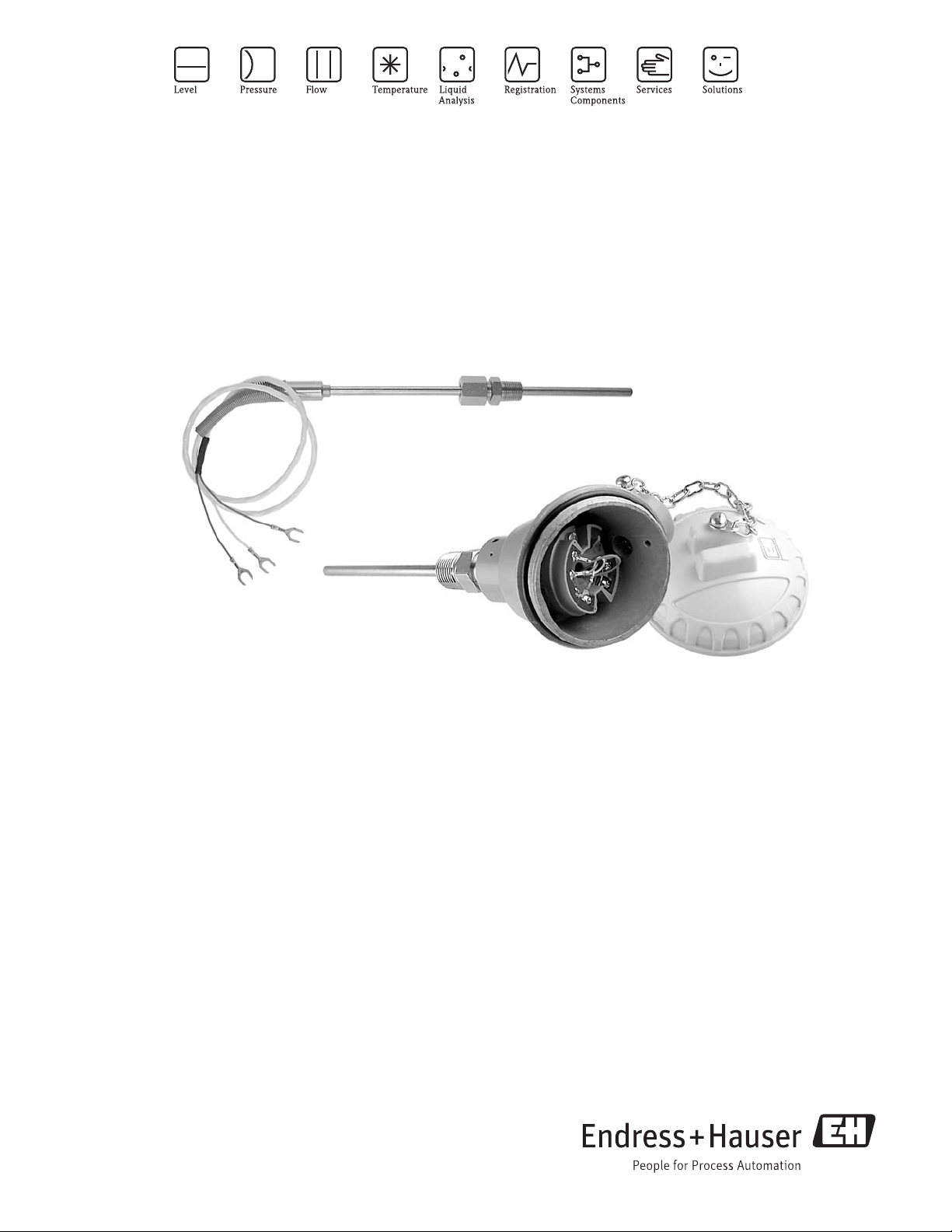
RTD TH11 and TH12
General purpose RTD with terminal head or conductor extension
lead wires for process and laboratory applications
Areas of application
The TH11 and TH12 temperature sensors are RTD's
designed for use in the process industry or factory
automation type of environment. They are made up
of a measurement probe with a RTD, insulation and
sheath.
Among other applications the sensors can be used on:
• Heat exchangers
• Power & recovery area
• Carbon regeneration furnace
•Dryers
• Flue Gas
• Compressor stations
• Process reactors
Head Transmitters
Instead of directly wiring your temperature sensors to
your control system, use transmitters to reduce
wiring and maintenance costs while increasing
measurement accuracy.
TI00108R/24/en
71147552
Your benefits
• High flexibility due to modular assembly with standard
terminal heads and customized immersion length
• One Source shopping for temperature measurement
solutions. World class transmitter with integrated sensor
offering.
- Remove and Install straight out of the box!
• Improved Galvanic Isolation on most devices (2 kV)
• Simplified Model Structure: Competitively priced, offers
great value. Easy to order and reorder. A single model
number includes sensor and transmitter assembly for a
complete point solution
• All iTEMP
stability ≤ 0.05 % per year
• Fast response time with reduced/tapered tip form
®
transmitters provide long term
Page 2
TH11, TH12
Function and system design
Measuring principle These resistance thermometers use a Pt100 temperature sensor according to IEC 60751. This temperature
sensor is a temperature-sensitive platinum resistor with a resistance of 100 Ω at 0 °C (32 °F) and a temperature
coefficient is α = 0.003851 °C
There are generally two different kinds of platinum resistance thermometers:
• Wire wound (WW): Here, a double coil of fine, high-purity platinum wire is located in a ceramic support.
This is then sealed top and bottom with a ceramic protective layer. Such resistance thermometers not only
facilitate very reproducible measurements but also offer good long-term stability of the resistance/
temperature characteristic within temperature ranges up to 600 °C (1112 °F). This type of sensor is relatively
large in size and it is comparatively sensitive to vibrations.
• Thin film platinum resistance thermometers (TF): A very thin, ultrapure platinum layer, approx. 1 μm
thick, is vaporized in a vacuum on a ceramic substrate and then structured photolithographically. The
platinum conductor paths formed in this way create the measuring resistance. Additional covering and
passivation layers are applied and reliably protect the thin platinum layer from contamination and oxidation
even at high temperatures.
The primary advantages of thin-film temperature sensors over wire wound versions are their smaller sizes and
better vibration resistance. A relatively low principle-based deviation of the resistance/temperature
characteristic from the standard characteristic of IEC 60751 can frequently be observed among TF sensors at
high temperatures. As a result, the tight limit values of tolerance category A as per IEC 60751 can only be
observed with TF sensors at temperatures up to approx. 300 °C (572 °F). For this reason, thin-film sensors are
generally only used for temperature measurements in ranges below 400 °C (932 °F).
-1
.
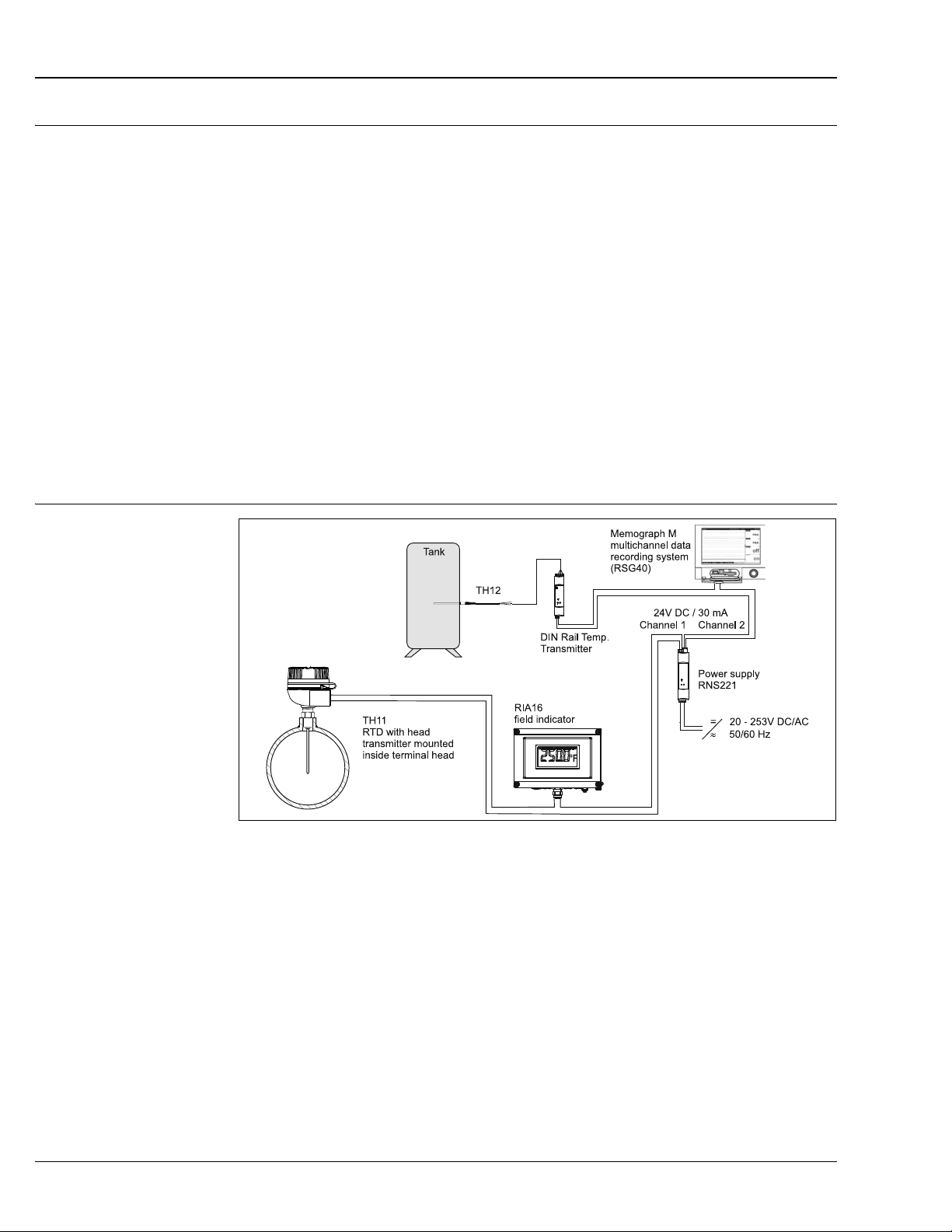
Measuring system
Example of an application of the temperature assemblies
A0016255-EN
RIA16 Field indicator
The field indicator records an analog measuring signal and shows this on the display. The LCD display shows
the currently measured value digitally and as a bargraph with limit value violation signalling. The indicator is
looped into the 4 to 20 mA circuit and obtains the required energy from there. Details see Technical
Information (see "Documentation").
RNS221
The RNS221S power supply (24 V DC, 30 mA) has two galvanically isolated outputs for supplying voltage to
loop powered transmitters. The two channel power supply has a wide-range input for mains power, 20 to
253 V DC/AC, 50/60 Hz to be used in any electrical circuit. Details see Technical Information (see
"Documentation"). RNS221 is an UL recognized component to UL-3III-1.
2 Endress+Hauser
Page 3
TH11, TH12
Memograph M, RSG40
Multichannel data recording system with multicolored TFT display (170 mm/7 in screen size), galvanically
isolated universal inputs (U, I, TC, RTD, pulse, frequency), digital input, transmitter power supply, limit relay,
communication interfaces (USB, Ethernet, RS232/485), internal SD memory, external SD card and USB stick.
100 ms scan rate for all channels. Details see Technical Information (see "Documentation").
Equipment architecture The single element RTDs are designed to measure temperature in a variety of process and laboratory
applications. These RTDs are specifically designed for use in two different process temperature ranges and they
will provide accurate and repeatable temperature measurement through a broad range of -200 to 600 °C
(-328 to 1112 °F). Low range thin film RTDs -50 to 200 °C (-58 to 392 °F) are constructed using silver plated
copper internal leads, PTFE wire insulations with potting compounds to resist moisture penetration. High range
RTDs -200 to 600 °C (-328 to 1112 °F) are constructed with nickel internal leads inside swaged MgO insulated
cable to allow higher temperature measurements at the RTD element and to provide higher temperature lead
protection along the sheath.
Measurement range
Family of temperature
transmitters
Construction Model code (class and type of sensor) max. range
Low temperature range
(thin film)
High temperature range
(wire wound)
TH11-_ _ _ (A/C/E/G/J/L) _ _ _ _ _ _
TH12-_ _ _ (A/C/E/G/J/L) _ _ _ _ _ _
TH11-_ _ _ (B/D/F/H/K/M) _ _ _ _ _ _
TH12-_ _ _ (B/D/F/H/K/M) _ _ _ _ _ _
-50 to 200 °C (-58 to 392 °F)
-200 to 600 °C (-328 to 1112 °F)
System components
Thermometers fitted with iTEMP® transmitters are an installation ready complete solution to improve
temperature measurement by increasing accuracy and reliability, when compared to direct wired sensors, as
well as reducing both wiring and maintenance costs.
PC programmable head transmitter TMT180 and TMT181
They offer a high degree of flexibility, thereby supporting universal application with low inventory storage. The
®
transmitters can be configured quickly and easily at a PC. Endress+Hauser offers the ReadWin® 2000
iTEMP
configuration software for this purpose. This software can be downloaded free of charge at
www.readwin2000.com. More information can be found in the Technical Information (see
"Documentation" section).
®
TMT182 head transmitter
HART
®
communication is all about easy, reliable data access and getting additional information about the
HART
measurement point more inexpensively. It can be installed as an intrinsically safe apparatus in zone 0 hazardous
areas and is used for instrumentation in the flat face terminal head to DIN EN 50446. iTEMP
integrate seamlessly into your existing control system and provide painless access to numerous diagnostic
information.
Configuration with a hand-held (Field Xpert SFX100 or DXR375) or a PC with configuration program
(FieldCare, ReadWin
®
2000) or configure with AMS or PDM. Details see Technical Information (see chapter
"Documentation").
®
transmitters
Endress+Hauser 3
Page 4
Type of transmitter Specification
®
iTEMP
TMT18x
• Material: Housing (PC), Potting (PUR)
• Terminals: Cable up to max. ≤ 2.5 mm
wire end ferrules
• Eyelets for easy connection of a HART
clips
• Degree of protection NEMA Type 4x Encl. (see also type of terminal head)
Details see Technical Information (see chapter "Documentation")
A0016380
HART® programmable head transmitter iTEMP® TMT82
The iTEMP® TMT82 is a 2-wire device with two measurement inputs and one analog output. The device
transmits both converted signals from resistance thermometers and thermocouples as well as resistance and
voltage signals via the HART
®
communication. It can be installed as an intrinsically safe apparatus in zone 0
hazardous areas and is used for instrumentation in the flat face terminal head to DIN EN 50446. Fast and easy
operation, visualization and maintenance via PC using configuration software such as FieldCare, Simatic PDM
or AMS.
Benefits are: Dual sensor input, maximum reliability, accuracy and long-term stability for critical processes,
mathematical functions, monitoring of thermometer drift, backup function of the sensor, diagnostic functions
of the sensor and sensor-transmitter matching based on the Callendar/Van Dusen coefficient. For more
information, refer to the Technical Information (see chapter "Documentation").
TH11, TH12
2
/ 16 AWG (secure screws) or with
®
-handheld terminal with alligator
®
PROFIBUS
Universally programmable head transmitter with PROFIBUS
PA TMT84 head transmitter
®
PA communication. Converting various input
signals into a digital output signal. High accuracy over the complete ambient temperature range. It can be
installed as an intrinsically safe apparatus in zone 0 hazardous areas and is used for instrumentation in the flat
face terminal head to DIN EN 50446. Swift and easy operation, visualization and maintenance using a PC
directly from the control panel, e. g. using operating software such as FieldCare, Simatic PDM or AMS.
Benefits are: dual sensor input, highest reliability in harsh industrial environments, mathematic functions,
thermometer drift monitoring, sensor back-up functionality, sensor diagnosis functions and sensor-transmitter
matching using Callendar-Van Dusen coefficients. Details see Technical Information (see chapter
"Documentation").
FOUNDATION Fieldbus™ TMT85 head transmitter
Universally programmable head transmitter with FOUNDATION Fieldbus™ communication. Converting
various input signals into a digital output signal. High accuracy over the complete ambient temperature range.
It can be installed as an intrinsically safe apparatus in zone 0 hazardous areas and is used for instrumentation
in the flat face terminal head to DIN EN 50446. Swift and easy operation, visualization and maintenance using
a PC directly from the control panel, e. g. using operating software such as FieldCare from Endress+Hauser or
the NI Configurator from National Instruments.
Benefits are: dual sensor input, highest reliability in harsh industrial environments, mathematic functions,
thermometer drift monitoring, sensor back-up functionality, sensor diagnosis functions and sensor-transmitter
matching using Callendar-Van Dusen coefficients. Details see Technical Information (see chapter
"Documentation").
4 Endress+Hauser
Page 5
TH11, TH12
24.1 (0.95)
33 (1.3)
Ø44 (1.73)
Ø7 (0.28)
Ø5 (0.2)
B
C
A
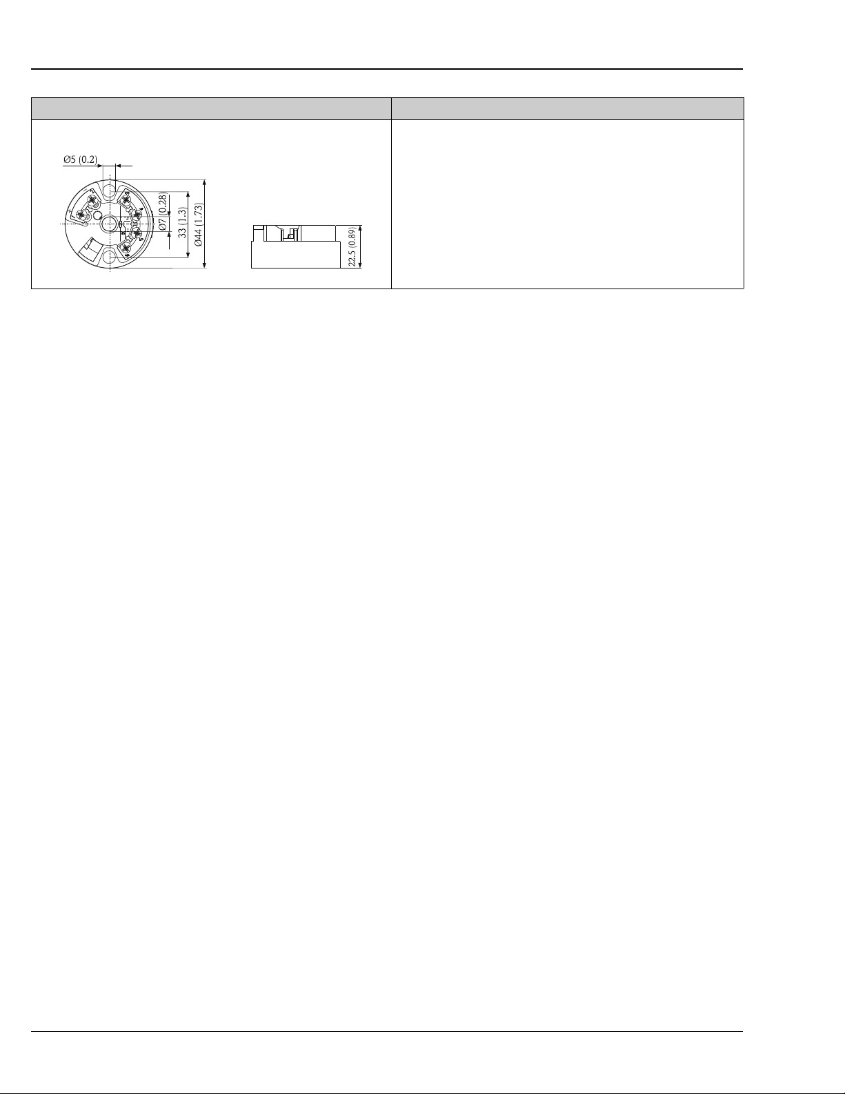
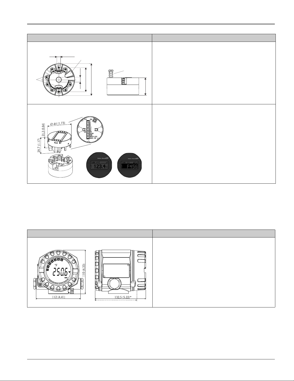
Type of transmitter Specification
®
TMT8x
iTEMP
Pluggable display TID10 as option
• Spring range L ≥ 5 mm (0.2 in), see Pos. A
• Fixing elements for pluggable measured value display, see Pos. B
• Interface for contacting measured value display, see Pos. C
• Material (RoHS-compliant)
Housing: PC
Potting: PU
•Terminals:
Screw terminals (cable up to max. ≤ 2.5 mm
or spring terminals (e. g. from 0.25 mm
for flexible wires with wire-end ferrules with plastic ferrule)
• Degree of protection NEMA Type 4x Encl. (see also type of terminal head)
A0007301
Details see Technical Information (see chapter "Documentation")
• Displays the actual measured value and the measurement point identification
• Displays fault events in inverse color with channel ident and diagnostics code
• DIP-switches on the rear for hardware set-up, e. g. PROFIBUS
address
Display is only available with suitable terminal head with display window, e.g.
TA30
2
/ 16 AWG)
2
to 0.75 mm2/ 24 AWG to 18 AWG
®
PA bus
A0009955
iTEMP® TMT162 field transmitter
Field transmitter with universal communication (HART®, PA, FF) and blue backlit display. Can be read easily
from a distance, in sunlight and at night. Large measurment value, bargraph and fault indication display.
Benefits are: dual sensor input, highest reliability in harsh industrial environments, mathematic functions,
thermometer drift monitoring and sensor back-up functionality, corrosion detection.
Type of transmitter (dimensions in mm [in]) Specification
®
Temperature field transmitter iTEMP
TMT162 for general purpose
• Material: Die-cast aluminium housing AlSi10Mg/AlSi12 with powder
coating on polyester base
• Separate electronics compartment and connection compartment
• Display rotatable in 90° increments
• Cable entry: 2 x ½" NPT
• Degree of protection: NEMA Type 4x Encl. (IP67)
• Brilliant blue backlit display with ease of visibilty in bright sunshine or pitch
darkness
• Gold plated terminals to avoid corrosion and additional measurement errors
Details see Technical Information (see "Documentation")
* Dimensions without display = 112 mm (4.41")
A0016656
Endress+Hauser 5
Page 6
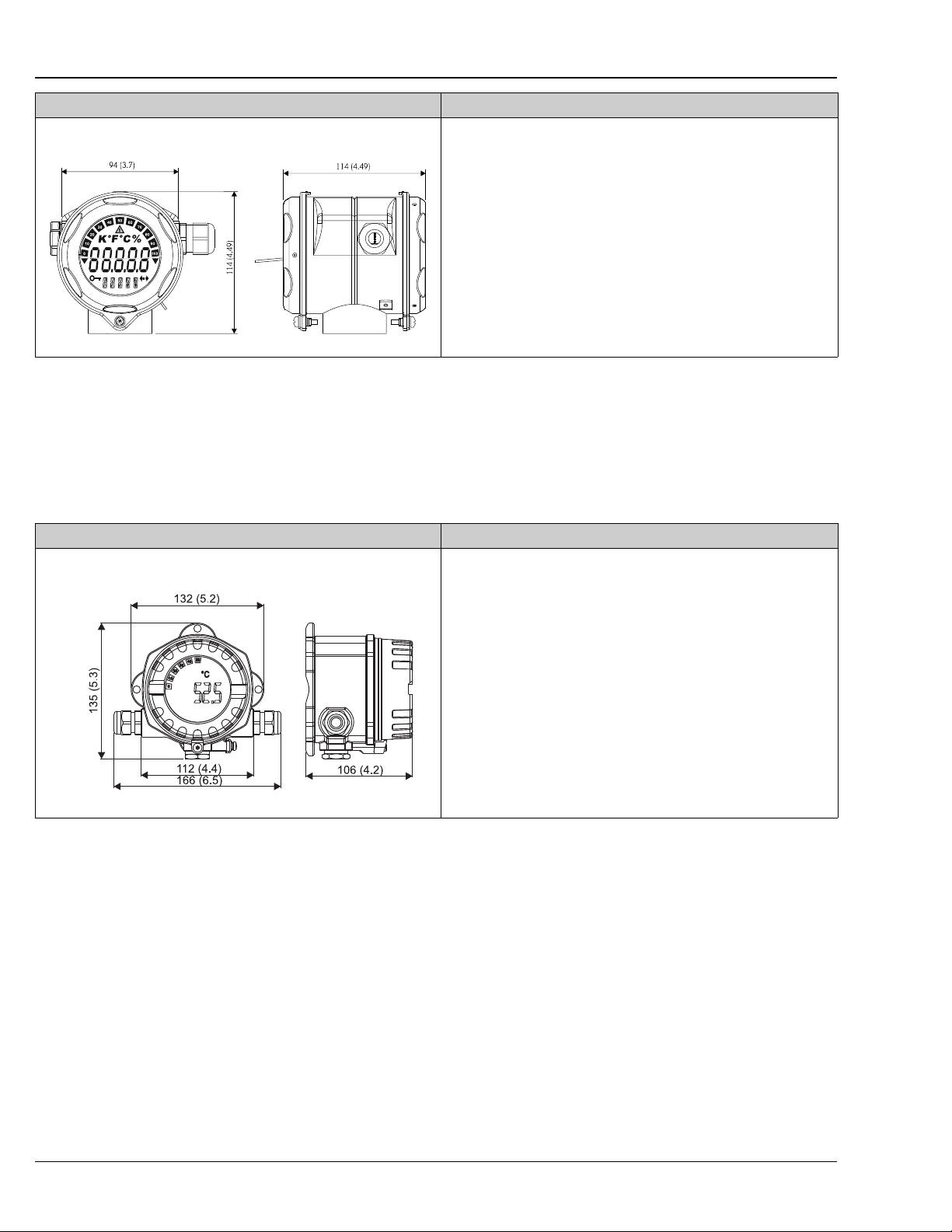
Type of transmitter (dimensions in mm [in]) Specification
Temperature field transmitter iTEMP® TMT162 for hygienic applications
• Material: Stainless steel 1.4435 (AISI 316L) for hygienic applications (T17
housing)
• Separate electronics compartment and connection compartment
• Display rotatable in 90° increments
• Cable entry: 2 x ½" NPT
• Degree of protection (IP69K)
• Brilliant blue backlit display with ease of visibility in bright sunshine or pitch
darkness
• Gold plated terminals to avoid corrosion and additional measurement errors
Details see Technical Information (see "Documentation")
A0016655
Field transmitter TMT142 - Single compartment housing
®
Field transmitter with HART
communication. The one channel TMT142 allows for cost effective replacement
of smaller transmitters with tiny display and old style analog transmitters. Large and brilliant blue backlit
display. Regardless of whether you install the transmitter in a dark location or in direct sunlight, you still get a
clear temperature reading. Reliable temperature measurment through advanced diagnostics. For details, see
Technical Information.
TH11, TH12
Type of transmitter (dimensions in mm [in]) Specification
Temperature field transmitter iTEMP
HART® TMT142
• Material: Die-cast aluminium housing AlSi10Mg/AlSi12 with powder
®
coating on polyester base
• Display rotatable in 90° increments
• Cable entry: 3 x ½" NPT
• Degree of protection NEMA Type 4x Encl. (IP67)
• Brilliant blue backlit display with ease of visibility in bright sunshine or pitch
darkness
• Gold plated terminals to avoid corrosion and additional measurement errors
Details see Technical Information (see "Documentation")
T09-TMT142ZZ-06-00-06-xx-000
6 Endress+Hauser
Page 7

TH11, TH12
Housing
Type of housing (dimensions in mm [in]) Specification
TA30A
TA30H
• Degree of protection: IP66/68
• Temperature: -50 °C to +150 °C (-58 °F to +302 °F) without cable gland
• Material: aluminium, polyester powder coated
Seals: silicone
• Cable entry incl. glands: ½" NPT and M20x1.5, only thread: G½",
plugs: M12x1 PA, 7/8" FF
• Protection armature connection: M24x1.5
• Head color: blue RAL 5012
• Cap color: gray RAL 7035
• Weight: 420 g (14.81 oz)
• Head transmitter optional with TID10 display
A0009821
• Flameproof (XP) version, explosion-protected, captive screw cap
• Degree of protection: IP66/68
• Temperature: -50 °C to +150 °C (-58 °F to +302 °F) for rubber seal without
cable gland (observe max. permitted temperature of the cable gland!)
• Material: aluminium; polyester powder coated
• Cable entry glands:
½" NPT, ¾" NPT, M20x1.5, only thread G½";
plug: M12x1 PA, 7/8" FF
• Neck tube/thermowell connection: ½" NPT
• Color of head: blue, RAL 5012
• Color of cap: gray, RAL 7035
• Weight: 860 g (30.33 oz)
• Head transmitter optionally available with TID10 display
Terminal head Al (dimensions in inch)
Terminal head plastic (dimensions in inch)
A0009831
• Material: Die-cast Aluminium head
• Sensor connection: ½" NPT Female
• Cable entry: ½" NPT or ¾" NPT Female ½" NPT has got Al reducer bushing
• Color of head: Spray SPU, RAL 5012
• Color of cap: Spray SPU, RAL 7035
• Coating thread (body-cover), lubricant acc. E+H standard, MgO coating;
benefits include ease of opening/closing cover and improved thread
engagement. Improves life time of the terminal head.
• Degree of protection NEMA Type 4x Encl. (IP 66/68)
T09-TH11xxxx-06-xx-xx-ae-001
• Polyprolylene, FDA compliant
• Sensor connection: ½" NPT Female
• Cable entry: ½" NPT or ¾" NPT Female ½" NPT with nylon reducer bushing
(FDA compliant)
• Degree of protection NEMA Type 4x Encl.
T09-TH11xxxx-06-xx-xx-ae-000
Endress+Hauser 7
Page 8

Type of housing (dimensions in mm [in]) Specification
Terminal head deep drawn stainless steel, TA20J style
• Material: Deep drawn stainless steel AISI 316L SS (hygienic design)
• Optional with display and/or head transmitter
• Sensor connection: ½" NPT female
• Cable entry: ½" NPT female
• Degree of protection NEMA Type 4x Encl. (IP66)
Display:
• 4 digits 7-segments LC display (loop powered)
• Maximum error: 0.1% of programmed range
• Loop drop: 2.5 V at 22 mA
• Max. ambient temperature: -20 to 70°C (-4 to 160 °F)
The programming is executed through 3 keys mounted on the bottom of the
display.
TH11, TH12
* dimensions with optional display
Compression fitting All dimensions in inches
Type of fitting Sheath Ø
Material
• One time adjustable fitting
316 Stainless Steel coldfinished bar stock in accordance with ASTM A-479. Shaped bodies are machined
from close-grained 316 stainless steel forgings in accordance with ASTM A-182.
• Re-adjustable fitting
316 Stainless Steel with TFE ferrule.
A0005938
T09-TH1112xx-03-xx-xx-ae-000
Process
(T)
1/16" 1/8"-27 NPT 1.03 5/16" 7/16"
1/8"
3/16"
¼" 1/8"-27 NPT 1.29 9/16" ½"
¼" ¼"-18 NPT 1.49 9/16" 9/16"
3/8" ¼"-18 NPT 1.57 11/16" 5/8"
connection
(PT)
1/8"-27 NPT 1.20 7/16" 7/16"
¼"-18 NPT 1.40 7/16" 9/16"
1/8"-27 NPT 1.23 ½" ½"
¼"-18 NPT 1.43 ½" 9/16"
Over all
length (L)
Nut Hex
(NH)
Body Hex
(BH)
Performance characteristics
Response time 63% response time per ASTM E644
Construction Ø 1/8" Ø 3/16" Ø ¼" Ø 3/8" red. 3/16"
High temp. range 2 s 2 s 3 s not available
Low temp. range 3 s 7 s 9 s 6 s
Response time for the sensor assembly without transmitter.
8 Endress+Hauser
Page 9

TH11, TH12
Maximum measured error RTD corresponding to IEC 60751
Sensor element Class max. Tolerances (°C) Temperature range
Thin film (TF) A ± (0.15 + 0.002 · |t|
B ± (0.3 + 0.005 · |t|
Wire wound (WW) A ± (0.15 + 0.002 · |t|
B ± (0.3 + 0.005 · |t|1) -200 °C to +600 °C (-328 °F to +1112 °F)
1) |t| = absolute value °C
For measured error in °F, calculate using equation above in °C, then multiply the outcome by 1.8.
Transmitter specifications
1
)
1
)
1
) -100 °C to +450 °C (-148 °F to +842 °F)
-50 °C to +200 °C (-58 °F to +392 °F)
TMT82 HART®/
TMT84 PA /
TMT85 FF
Measurment
accuracy ± typ. 0.25 °C (0.45 °F)
Sensor current I ≤ 0.3 mA I ≤ 0.6 mA I ≤ 0.2 mA I ≤ 0.3 mA
Galvanic isolation
(input/output)
1) % is related to the adjusted measurement range (the larger value applies)
U = 2 kV AC - U = 2 kV AC
Transmitter long-term
stabiltiy
TMT180 Pt100 PCP TMT181
multifunctional
PCP
0.2 °C (0.36 °F), optional
0.1 °C (0.18 °F) or 0.08%
1
0.5 °C (0.9 °F) or 0.08%
TMT182 HART® TMT162 HART®
Field transmitter
1
≤ 0.105 °C (0.19 °F) 0.2 °C (0.36 °F)
≤ 0.1 °C/year (≤ 0.18 °F / year) or ≤ 0.05% / year
Data under reference conditions; % relates to the set span. The larger value applies.
TMT142
Insulation resistance Insulation resistance between terminals and probe sheath, test voltage 250 V.
• ≥100 MΩ at 25 °C (77 °F)
• ≥10 MΩ at 300 °C (572 °F)
Self heating RTD elements are not self-powered and require a small current be passed through the device to provide a
voltage that can be measured. Self-heating is the rise of temperature within the element itself, caused by the
current flowing through the element. This self-heating appears as a measurement error and is affected by the
thermal conductivity and velocity of the process being measured; it is negligible when an Endress+Hauser
®
temperature transmitter is connected.
iTEMP
Endress+Hauser 9
Page 10

Wiring
Wiring diagrams Type of sensor connection TH11
Head transmitter mounted
Head mounted transmitter iTEMP® TMT8x (dual input)
TH11, TH12
A0016433-EN
A0008848-EN
10 Endress+Hauser
Page 11

TH11, TH12
Head mounted transmitter iTEMP® TMT162
Head mounted transmitter iTEMP® TMT142
T09-TMT162ZZ-04-00-XX-en-000
T09-TMT142ZZ-04-00-XX-en-003
Endress+Hauser 11
Page 12

Terminal block mounted
TH11, TH12
T09-TH1112xx-04-xx-XX-ae-001
Wire specifications TH11
24AWG, 19 strand silver plated copper with 0.010” PTFE extruded outer, 1/8” sensors have 28AWG seven
strand wires with the same extrusion.
TH12
24AWG, seven strand silver plated copper with 0.010” PTFE then 0.015” FEP outer jacket, 1/8” sensors are
28AWG, seven strand SPC, 0.010” PTFE, 0.015” FEP white outer jacket. Flex armor is 0.272” nominal OD,
304SS 0.010” thick , square lock style.
The maximum temperature for the extension cable is 200 °C (392 °F).
TH12 is available only with conductor external lead wires, DIN rail transmitters (TMT121 PCP /
TMT122 HART
®
) are available, see "Documentation".
The blocks and transmitters are shown as they sit inside the heads in reference to the conduit opening.
12 Endress+Hauser
Page 13

TH11, TH12
Installation conditions
Orientation No restrictions for installation orientation.
Installation instructions
Ambient temperature
Installation examples
A - B: In pipes with a small cross section the sensor tip should reach or extend slightly past the center line of the pipe (= L).
C - D: Tilted installation.
A0009538
The immersion length of the thermometer influences the accuracy. If the immersion length is too small then
errors in the measurement are caused by heat conduction via the process connection and the container wall.
If installing into a pipe then the immersion length must be half of the pipe diameter, ideally.
• Installation possibilities: Pipes, tanks or other plant components
• Minimum immersion length = 80 to 100 mm (3.15 to 3.94 in)
The immersion length should correspond to at least 8 times of the thermowell diameter. Example:
Thermowell diameter 12 mm (0.47 in) x 8 = 96 mm (3.8 in). A standard immersion length of 120 mm
(4.72 in) is recommended
• ATEX certification: Always take note of the installation regulations!
When operating in small nominal bore pipes it must be guaranteed that the thermowell tip is extending far
enough into the process to reach out past the pipe center line (see Pos. A and B). A further solution could be
an angled (tilted) installation (see Pos. C and D). When determining the immersion length all thermometer
parameters and the process to be measured must be taken into account (e.g. flow velocity, process pressure).
Environmental conditions
Terminal head Temperature in °C (°F)
Without mounted head transmitter Depends on the terminal head used and the cable gland or fieldbus connec-
tor, see 'Terminal heads' section, → ä 7
With mounted head transmitter -40 to 85 °C (-40 to 185 °F)
With mounted head transmitter and display -20 to 70 °C (-4 to 158 °F)
Shock and vibration resistance 4G / 2 to 150 Hz as per IEC 60068-2-6
Endress+Hauser 13
Page 14

Process conditions
Process pressure limits p/T load curve example for low temperature range - thin film construction according to Dittrich.
• L = insertion length
= flow velocity air
•v
a
•v
= flow velocity water or steam
w/s
Example calculation: Probe = 316 SS
sheath ∅ = ¼", 0.028" wall thickness
Avoid resonance frequency as this will
cause damage to the probe!
• L = 4 and 6 in:
Resonance frequency occurs when
permanent flow velocity is at 18.1,
22.6 or 27.1 ft/s (air) for 6 in and/or
40.5, 50.6 or 60.8 ft/s (air) for 4 in
probe (T = 482 °F, p = 2700/2600
psi).
• L = 9 and 12 in:
Resonance frequency occurs when
permanent flow velocity is at 8.1, 10.1
or 12.1 ft/s (air) for 9 in and/or 4.6,
5.7 or 6.8 ft/s (air) for 12 in probe (T
= 482 °F, p = 2600 psi).
TH11, TH12
T09-TH1112xx-05-xx-xx-ae-000
T09-TH1112xx-05-xx-xx-ae-001
Max. allowable process pressure (PSIG) for instrumentation with one time adjustable compression fittings.
Temperature 1/8" NPT & ¼" NPT compression fitting
°F °C sheath Ø = 1/8"
x 0.012" wall
thickness
-20 to 300 -28 to 149 2850 3150 3350 3900
400 204 2750 3050 3250 3800
500 260 2550 2850 3000 3500
600 316 2400 2700 2850 3300
700 371 2350 2600 2750 3200
800 427 2300 2550 2650 3100
900 482 2200 2450 2600 3050
1000 538 2100 2300 2450 2850
1) Not available with compression fittings 1/8" NPT
sheath Ø = 3/16"
x .0.020" wall
thickness
sheath Ø = ¼" x
0.028" wall
thickness
sheath Ø = 3/8"
x 0.12" wall
thickness
1
For high temperature range construction with compacted magnesium oxide (MgO) the values might
be higher. In any case for different length, other materials, variation in sheath diameter or wall
thicknesses stress analysis is recommended. Failures are caused by forces imposed by static pressure,
steady state flow and vibration.
Re-adjustable compression fittings are not intended to be used for pressure retaining applications and
should only be used tor the mechanical holding of sensors.
14 Endress+Hauser
Page 15

TH11, TH12
Design, dimensions
Mechanical construction
For values related to this graphic please refer to the table below.
Dimensions in inches:
Immersion length X Wire length B Sheath diameter A
TH11 TH12
4", 6", 9", 12" 6", 12", 18", 24"
specified length 2" to 96" in ½"
increments
1) High temperature version is not available with reduced tip.
Weight From 1 to 5.5 lbs
Material Wetted parts 316 SS
48", 72", 120"
specified length
12" to 300" in
12" increments
(A’)
1/8 in 316 SS 0.012" -
3/16 in 316 SS 0.020" -
¼ in 316 SS 0.028" -
3/8 in (A’) red.
3/16 in (A) 316 SS
Wall thickness s Reduced
0.120" (0.016" at tip) 1¼"
1
T09-TH1112xx-06-xx-xx-ae-000
length L
Endress+Hauser 15
Page 16

TH11, TH12
Certificates and approvals
CE Mark The iTEMP® Series of temperature transmitters complies with the legal requirements laid out within the EU
regulations.
Other standards and
guidelines
UL Temperature transmitter are recognized components to UL 3111-1 (iTEMP
• IEC 60529:
Degrees of protection by housing (IP-Code).
• IEC 61010:
Safety requirements for electrical measurement, control and laboratory instrumentation.
• ASTM E644:
American society for testing and materials, standard test methods for testing industrial
resistance thermometers.
• NEMA - ANSI / NEMA 250
Standardization association for the electrical industry.
• IEC 60571
Industrial platinum resistance thermometer
®
Series).
16 Endress+Hauser
Page 17

TH11, TH12
Ordering information
Detailed ordering information is available from the following sources:
•In the Product Configurator on the Endress+Hauser web page:
www.endress.com → Select country → Instruments → Select device → Product page function:
Configure this product
• From your Endress+Hauser Sales Center: www.endress.com/worldwide
Product Configurator - the tool for individual product configuration
• Up-to-the-minute configuration data
• Depending on the device: Direct input of measuring point-specific information such as measuring range or
operating language
• Automatic verification of exclusion criteria
• Automatic creation of the order code and its breakdown in PDF or Excel output format
• Ability to order directly in the Endress+Hauser Online Shop
Documentation
Short operation manual:
• TH11 RTD temperature sensor (KA178r/24/ae)
• TH12 RTD temperature sensor with cable (KA179r/24/ae)
Technical Information:
• Temperature head transmitter:
–iTEMP® HART® TMT82 (TI01010T/09/en)
–iTEMP® PROFIBUS PA TMT84 (TI138R/09/en)
–iTEMP® FF TMT85 (TI134R/09/en)
–iTEMP
–iTEMP® HART® TMT162 (TI086r/24/ae)
–iTEMP® PCP TMT181 (TI070r/24/ae)
–iTEMP
–iTEMP® HART® TMT182 (TI078r/24/ae)
®
HART® TMT142 (TI107R/09/en)
®
Pt TMT180 (TI088r/24/ae)
Application example:
• Technical information:
– Field indicator RIA16 (TI00144R/09/en)
– Power supply RNS221 (TI081R/24/ae)
– Data Manager Memograph M, RSG40 (TI133R/09/en)
Endress+Hauser 17
Page 18

CanadaUSA
Endress+Hauser Canada
1075 Sutton Drive
Burlington, ON L7L 5Z8
Canada
Tel.905-681-9292
800-668-3199
Fax905-681-9444
www.ca.endress.com
Endress+Hauser, Inc.
2350 Endress Place
Greenwood, IN 46143
USA
Tel.317-535-7138
Fax317-535-8498
Sales888-ENDRESS
Service800-642-8737
inquiry@us.endress.com
www.us.endress.com
México
Endress+Hauser, México, S.A. de C.V.F
Fernando Montes de Oca 21 Edificio A Piso 3
Fracc. Industrial San Nicolas
54030. Tlalnepantla de Baz
México
Tel.+52 55 5321 2080
Fax+52 55
eh.mexico@mx.endress.com
www.mx.endress.com
Estado de México
5321 2099
Instruments International
Endress+Hauser
Instruments International AG
Kaegenstrasse 2
4153 Reinach
Switzerland
Tel.+41 61 715 81 00
Fax+41 61 715 25 00
www.endress.com
info@ii.endress.com
TI00108R/24/en/01.11
71147552
FM9.0
 Loading...