

Endress+Hauser Tankvision Multi Scan NXA83B Installation Instructions Manual
EA01242G/00/A2/01.18
71395230
Products
Solutions Services
*71395230*
71395230
Installation Instructions
Input cards, output cards
Tankvision Multi Scan NXA83B
Overview
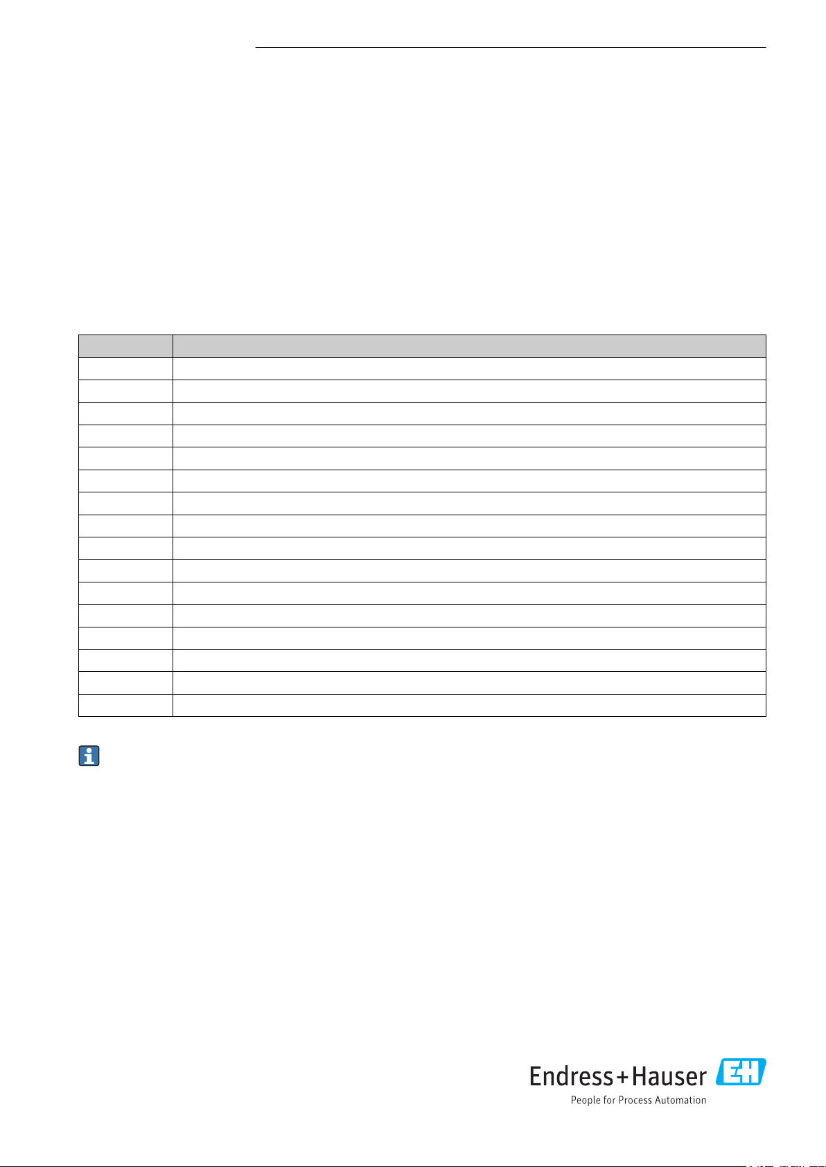
The manual applies to the following spare parts sets:
Order number Original spare part set
71351698 Input card Enraf GPU/BPM
71351702 Input card Varec Mark/Space
71351705 Input card Whessoe WM550
71351710 Input card SI6290
71351711 Input card Modbus RS232
71351712 Input card Modbus RS485
71351713 Input card E Saab TRL2
71351714 Input card FW9000 (DM-II, FW)
71351762 Input card Sakura V1
71351763 Output card Tankvision Pro. RS232
71351766 Output card Tankvision Pro. RS485
71351767 Output card Enraf GPU/RS232
71351768 Output card Modbus RS232
71351770 Output card Modbus RS485
71351773 Input/output card Redundancy link RS232
71352335 Input card L+J Tankway
We recommend that the Installation Instructions are kept with the packaging at all times.
EA01242G
=
www.endress.com/deviceviewer
2.
1.
3.
4.
?
Order code Description
Ser. No.: 12345
Designated use
The spare part set and the Installation Instruction are used to replace a faulty unit with a functioning unit of the same type. Use
genuine parts from Endress+Hauser only.
Only original spare part sets, intended by Endress+Hauser for the measuring device, must be used.
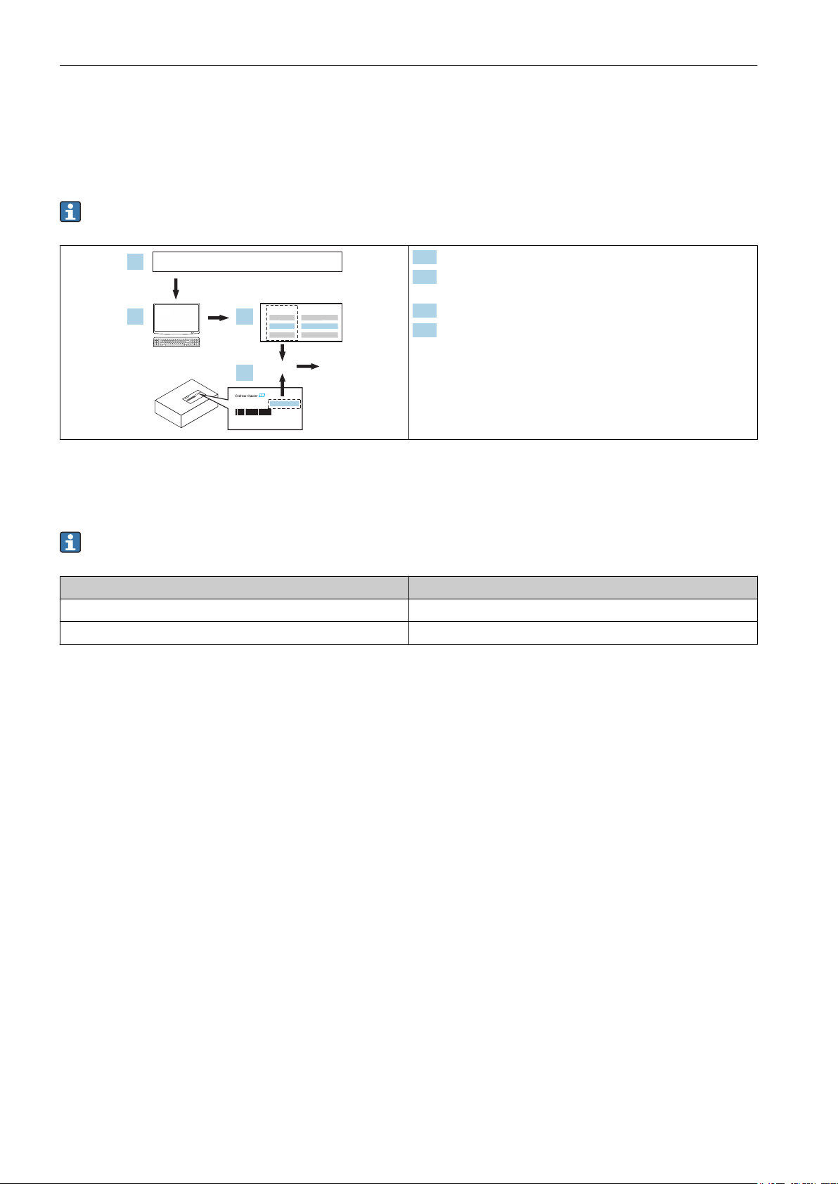
The verification has to be done via W@M Device Viewer; this procedure is explained below.
For some devices there is an overview of spare part sets inside the device. If the spare part set is listed there, the verification
is not required.
1. www.endress.com/deviceviewer
2. Enter serial number (Ser. No.), search for product data and click
on "spare parts".
3. List of all spare parts sets for the device.
4. Determine the order number of the spare part set.
The spare part set can only be used if the order number of the
spare part set corresponds to the order number on the spare part
list.
Authorized personnel
Authorization to carry out a repair depends on the approval of the measuring device. The table shows the respective group of
persons for each.
The person who carries out the repair is responsible for safety during the work, the quality of work completed and safety of
the device after repair.
Approval of the measuring device Group of persons authorized to carry out repairs
Without approval 1, 2, 3
With approval (e.g. IECEx) 1, 2, 3
1) 1 = Trained customer technician, 2 = Service technician authorized by Endress+Hauser, 3 = Endress+Hauser (send measuring device back
to manufacturer)
Safety instructions
• Check whether the spare part matches the identification
label on the measuring device, as explained on the first page.
• The spare parts set and Installation Instructions are used to
replace a faulty unit with a functioning unit of the same
type.
Use genuine parts from Endress+Hauser only.
• Comply with national regulations governing mounting,
electrical installation, commissioning, maintenance and
repair procedures.
• Requirements with regard to specialized technical staff for
the mounting, electrical installation, commissioning,
maintenance and repair of the measuring devices:
– trained in instrument safety.
– familiar with the individual operation conditions of the
devices.
– for Ex-certified measuring devices: also trained in
explosion protection.
• The measuring device is energized. Danger: Risk of electric
shock! Open the measuring device in a de-energized state
only.
• In the case of Ex-certified measuring devices: Only open in a
de-energized state (once a delay of 10 minutes has elapsed
1)
after switching off the power supply) or in environments
which do not have a potentially explosive atmosphere.
• In the case of measuring devices in safety-related
applications in accordance with IEC 61508 or IEC 61511:
After repair recommission in accordance with Operating
Instructions. Document the repair procedure.
• Before removing the device: set the process in a safe
condition and purge the pipe of dangerous materials.
• Hot surfaces! Risk of injury! Before commencing work, allow
the system and measuring device to cool down to a
touchable temperature.
• In the case of measuring devices in custody transfer, the
custody transfer status no longer applies once the lead seal
has been removed.
• Follow the Operating Instructions for the device.
• Risk of damaging electronic components! Ensure you have a
working environment protected from electrostatic discharge.
• After removing the electronics cover, there is a risk of
electric shock as shock protection is removed!
Switch off the measuring device before removing internal
covers.
• Modifications to the measuring device are not permitted.
2 Endress+Hauser
EA01242G
• Only open housing for a brief period. Avoid the penetration
of foreign bodies, moisture or contaminants.
• Replace defective seal/gaskets with genuine parts from
Endress+Hauser only.
• If threads are damaged or defective, the measuring device
must be repaired.
• Threads (e.g. of the cover for the electronics and connection
compartments) must be lubricated. Use an acid-free, nonhardening grease if an abrasion resistant dry lubricant is
non-existent.
• If spacing is reduced or the dielectric strength of the
measuring device cannot be guaranteed during repair work,
perform a test on completion of the work (e.g. high-voltage
test in accordance with the manufacturer's instructions).
• Service connector:
– Do not connect in potentially explosive atmospheres.
– Only connect to Endress+Hauser service devices.
• Observe the instructions for transporting and returning the
device outlined in the Operating Instructions.
If you have any questions, contact your
Endress+Hauser service organization.
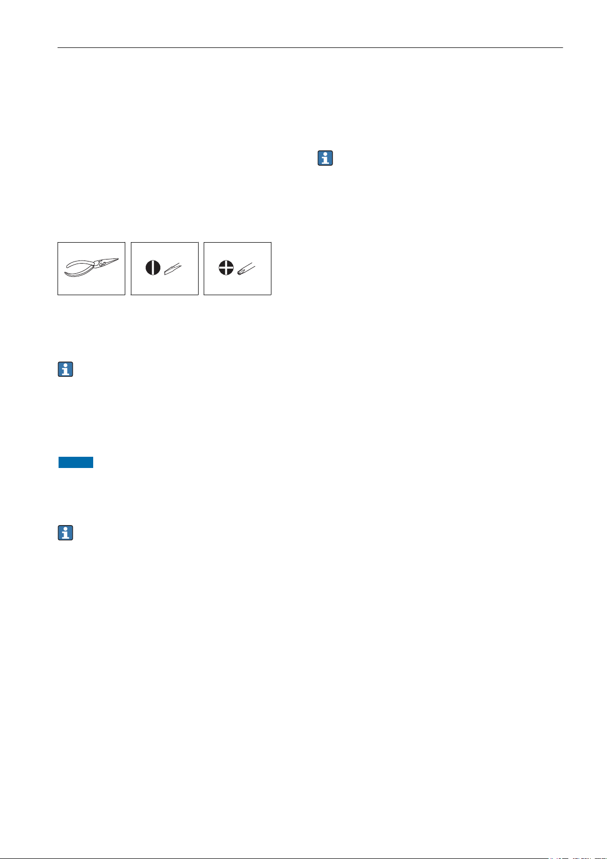
Tools list
For applications in custody transfer
The NXA83B is a device that is suitable for custody transfer measurement. According to international custody transfer
regulations, the device can be approved and sealed by an official for legal metrology controls after device commissioning.
• It is necessary to break the seal if a spare part needs to be replaced. The authority for legal metrology controls must be
notified of this within 24 hours.
• Once the spare part has been replaced, an official must approve and seal the NXA83B device once more.
Replacing input and output cards
Always make sure to de-energize the device before replacing any spare parts.
NOTICE
After the part has been replaced, the plug-in connections on the back of the device must be restored to their original state,
as the proper operation of the device cannot be guaranteed otherwise.
Mark the plug-in connections on the back of the housing.
‣
Install input and output cards in the original slot.
‣
The input and output cards require a supply voltage of 5 VDC, only the Sakura V1 input card requires 5 VDC and 12 VDC in
addition.
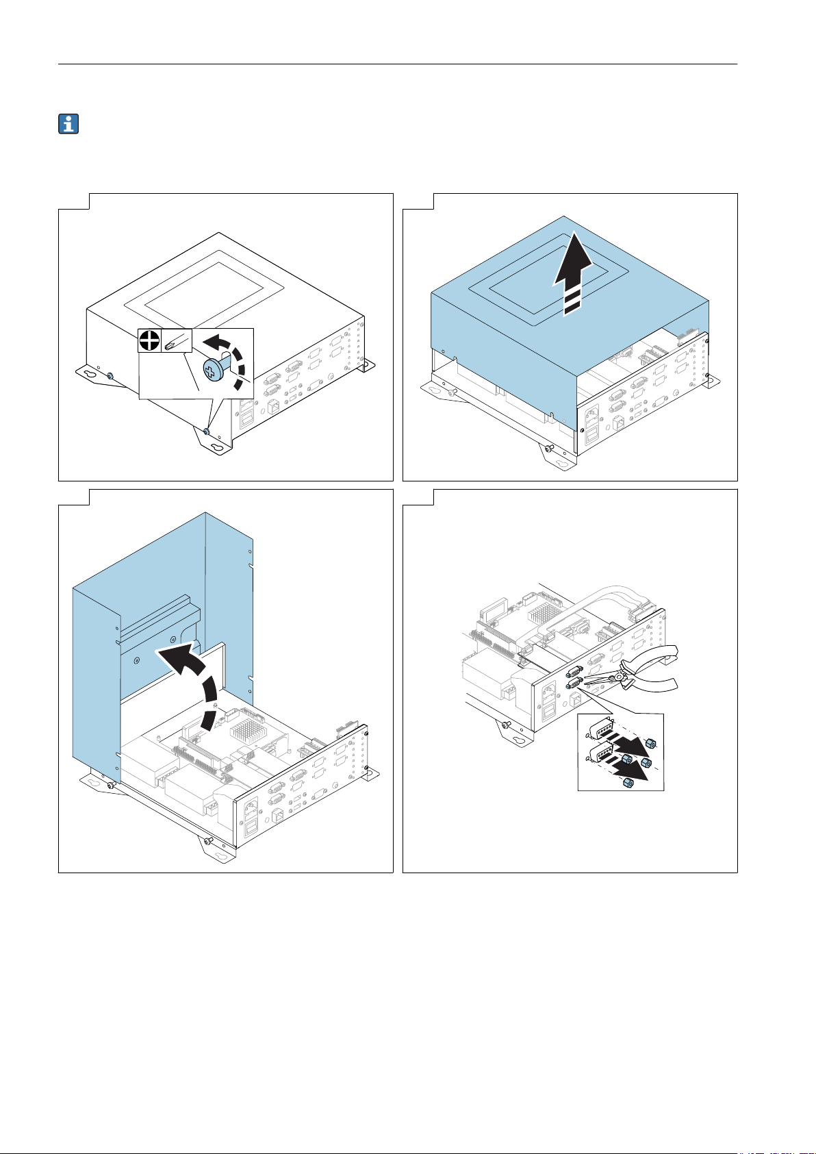
The procedure for replacing the input and output cards depends on the device design. The procedure for replacing cards in the
case of a wall-mount housing and a 19" rack is described below.
Endress+Hauser 3
EA01242G
Wall-mount housing
In the case of the wall-mount housing, the 8 slots are arranged in two parallel rows, one above the other.
• If the input/output card to be replaced is installed in the top row, steps 7 and 8 can be ignored.
• If the input/output card to be replaced is installed in the bottom row, the input/output card in the row above must also be
removed.
1 → 2 →
3 → 4 →
4 Endress+Hauser
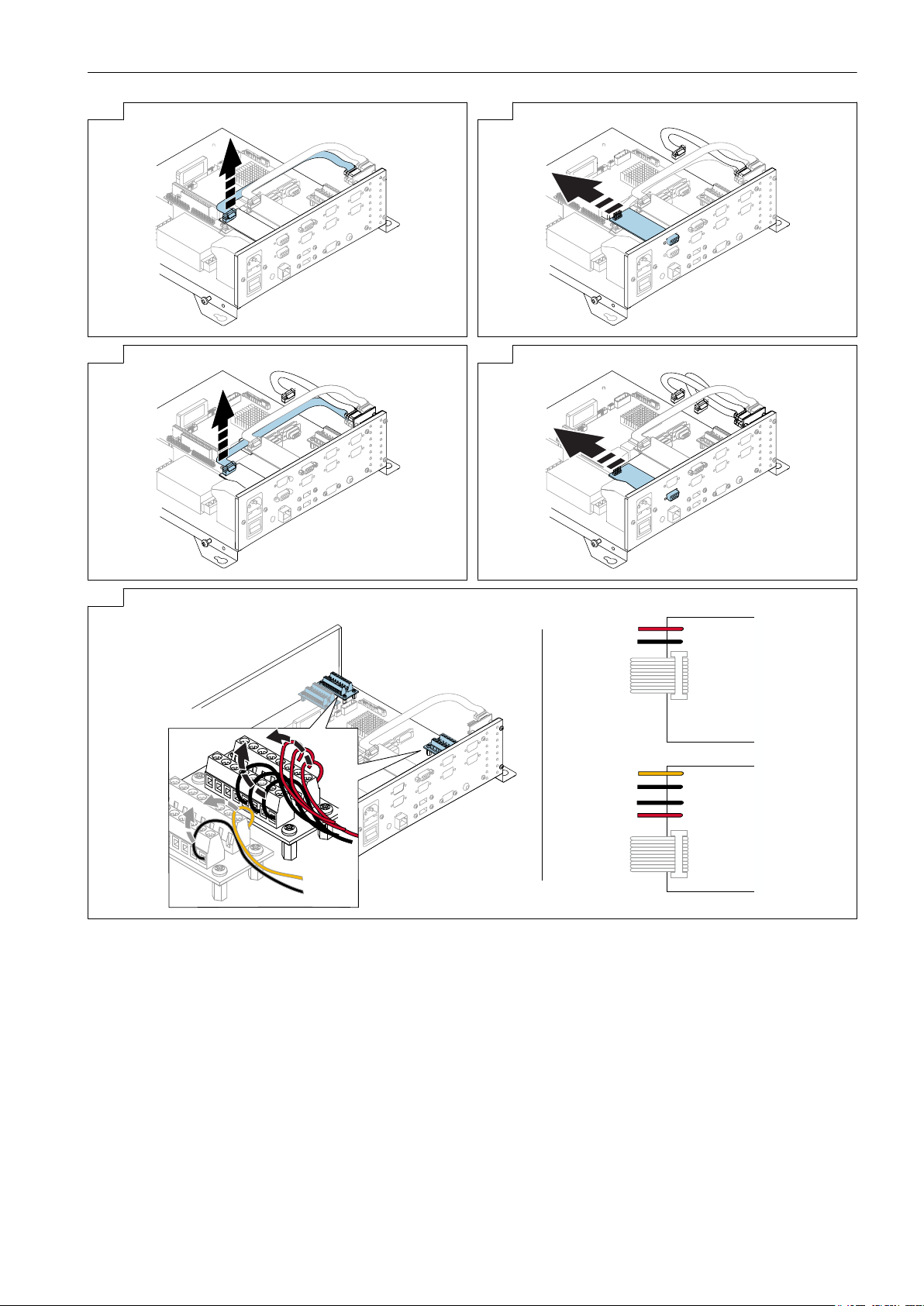
5 → 6 →
5 VDC
–
+
5 VDC
12 VDC
+
–
–
+
Sakura V1
YE
BK
RD
BK
BK
RD
12V
5V
YE
BK
BK
RD
7 → 8 →
EA01242G
9
Re-assembly is carried out in reverse order.
Endress+Hauser 5
 Loading...