

Page 1

Technical Information
Omnigrad S TMT142R
Compact RTD assembly
Temperature transmitter for for resistance thermometers, adjusta-
®
ble via HART
protocol
Application
The temperature assembly TMT142R from the
Omnigrad S family is a compact resistance thermometer
specifically designed to fulfill the requirements of
different process industries such as the chemical,
petrochemical and energy but even suitable to other
general purpose applications.
The thermometer assembly TMT142R consists of a
temperature RTD sensor insert (Pt 100) and an electronic
two-wire temperature transmitter providing a 4 to 20
mA output, configurable via HART
Thanks to the versatility of its product structure, the
TMT142R is easily adaptable to various applications in
many different industrial processes.
Your benefits
•HART® protocol for operating the device on site using
handheld terminal (DXR375) or remotely via the PC
• Illuminated display, rotatable
• Operation, visualization and maintenance with PC,
e.g. using FieldCare or ReadWin® 2000 operating software
• Pt 100 sensing element with class A accuracy (IEC
60751) or class1/3 DIN B
• Pt 100 wire wound for use in temperature range
-200 to 600°C (-328 to 1112 °F)
®
protocol.
• Single Pt 100 with 3 or 4 wires connection
• Undervoltage detection responds immediately, output
of falsified measured values is prevented
• Highly accurate in entire operating temperature range
• Sensor monitoring:
Failure conditioning, corrosion detection to NAMUR
NE 89; Failure conditioning in event of sensor break or
sensor short-circuit, adjustable to NAMUR NE 43
• EMC to NAMUR NE 21, CE
• Aluminum or stainless steel (optional) housing with
IP67 or NEMA 4x ingress protection degree
• Calibration certificate can be ordered together with
the assembly
• Output simulation
• Min./max. process value recorded
• Customized measuring range setup or expanded
SETUP, see questionnaire
• Approvals: ATEX (EEx ia, EEx d and dust ignitionproof), CSA (IS, NI, XP and DIP)
0 1
TI128R/09/en
71022415
Page 2
TMT142R
Function and system design
Measuring principle In the RTD thermometer (Resistance Temperature Detector) the sensing element is an electric resistor with a
100 Ohm resistance value at 0°C (so called Pt 100, according to the IEC 60751 standard norm). The resistance
value of a Pt 100 increases with temperature, depending on the physical characteristic of the used material
(platinum). In the industrial thermometers, according to the standard IEC 60751, the thermal coefficient of the
Pt 100 platinum sensors is α = 3.85*10
-3°C-1
, in the range between 0°C to 100°C.
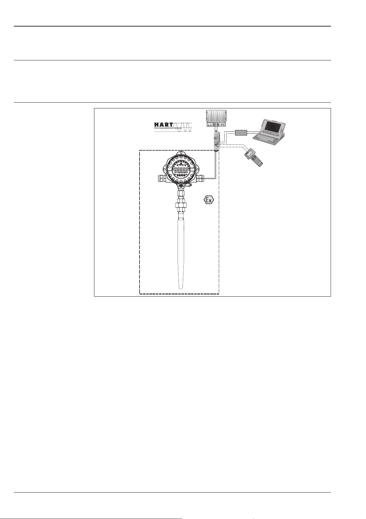
Measuring system
TMT142R,
TMT142C
FieldCare,
®
®
RN221N
Commubox
ReadWin 2000
PMC731:PIC0001
Online
>GroupSelect
1
2PV 0.7bar
HELP
DXR375
O
I
®
HART Communication
Example of an application of the compact thermometer
The Omnigrad S HART® TMT142R is a compact thermometer with a two-wire transmitter and an input for
resistance thermometers in 3-wire or 4-wire connection, and an analog output. The LC display shows the current measured value digitally and as a bar graph with an indicator for limit value violation. The TMT142R can
be operated via the HART
®
protocol using a handheld terminal (DXR375) or PC (FieldCare or ReadWin® 2000
operating software).
The sensor construction is based on the IEC 60751 standard, giving high reliability and performance in all the
typical industrial environment conditions.
The Pt 100 sensing element is a wire wound type (WW) and is placed in tip of the sensor. The measuring probe
(RTD replaceable insert) is installed in a thermowell.
Thanks to the spring load construction method, the sensing element is always in contact with the inner tip of
the thermowell in order to guarantee the best heat transfer from the process to the sensing element. The
transmitter housing is available either in coated aluminum or stainless steel (optional), with or without LC
display. The fit between housing, thermowell and cable gland ensures a minimum IP65 (Ingress Protection)
grade.
The thermowell can be either welded or made from bar-stock material. The thermowells are available in
different forms and with many process connections: threads, flanges or weld-in types (see the paragraph
“Thermowell”).
Corrosion detection
Sensor connection line corrosion can corrupt the measured value. For this reason, the device gives you the
opportunity to detect corrosion for thermocouples and resistance thermometers with a 4-wire connection
before measured value corruption takes place.
2 Endress+Hauser
Page 3

TMT142R
Input
Measured variable Temperature (temperature linear transmission behavior)
Measuring range The transmitter records different measuring ranges depending on the sensor connection and input signals (see
'Type of input').
Type of input
Input Designation Measuring range limits Min. span
Resistance thermometer (RTD)
to IEC 751
(α = 0.00385)
to JIS C1604-81
(α = 0.003916)
to DIN 43760
(α = 0.006180)
to Edison Copper Winding
No.15
(α = 0.004274)
to SAMA
(α = 0.003923)
to Edison Curve
(α = 0.006720)
to GOST
(α = 0.003911)
to GOST
(α = 0.004278)
Pt100
Pt100
Pt100
Pt100
Pt100 (Callendar - van
Dusen)
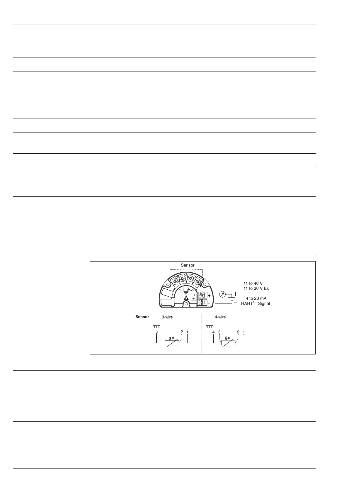
• Type of connection: 3- or 4-wire connection
• With 3-wire and 4-wire connection, sensor wire resistance to max. 50 Ω per wire
• Sensor current: ≤ 0.3 mA
-200 to 850 °C (-328 to 1562 °F)
-200 to 649 °C (-328 to 1200 °F)
-100 to 700 °C (-148 to 1292 °F)
-200 to 850 °C (-328 to 1562 °F)
-200 to 850 °C (-328 to 1562 °F)
10 K
10 K
10 K
10 K
10 K
Response time Tests in water at 0.4 m/s (according to IEC 60751; 23 to 33°C step changes), without thermowell
• t50: 2.5 s
• t90: 7 s
Self heating Negligible
Endress+Hauser 3
Page 4
Output
Output signal Analog 4 to 20 mA, 20 to 4 mA
Signal on alarm • Underranging:
Linear drop to 3.8 mA
• Overranging:
Linear rise to 20.5 mA
• Sensor break; sensor short-circuit:
≤ 3.6 mA or ≥ 21.0 mA (configurable 21.6 mA to 23 mA)
TMT142R
Load Max. (V
Linearization/transmission behavior
Filter 1
Galvanic isolation U = 2 kV AC (input/output)
Input current required ≤ 3.5 mA
Current limit ≤ 23 mA
Switch-on delay 4 s (during switch-on operation I
power supply
Temperature linear, resistance linear, voltage linear
st
order digital filter: 0 to 60 s
- 11 V) / 0.022 A (current output)
Power supply
Electrical connection
= 4 mA)
a
Supply voltage Ub= 11 to 40 V (8 to 40 V without display), reverse polarity protection
Warning!
Power must be fed to the device from an 11 to 40 VDC power supply in accordance with NEC Class 02 (low
voltage/current) with short-circuit power limit to 8 A/150 VA.
Cable entry See "Product structure"
Residual ripple Perm. residual ripple U
≤ 3 V at Ub ≥ 13.5 V, f
ss
max.
= 1 kHz
4 Endress+Hauser
Page 5

TMT142R
Accuracy
Response time 1 s per channel
Reference operating conditi-
Calibration temperature: +25 °C ± 5 K (77 °F ± 9 °F)
ons
Maximum measured error Maximum error of the Pt 100 (WW) sensing element
Ê Cl. A 3σ = 0.30+0.0050ItI -200 to 600°C (-328 to 1112 °F)
Ê Cl. 1/3 DIN B 3σ = 0.10+0.0017It|
3σ = 0.30+0.0050ItI
-50 to 250°C (-58 to 482 °F)
-200 to -50 / 250 to 600°C
(-328 to -58/482 to 1112 °F)
(ItI=absolute value of the temperature in °C)
Transmitter maximum measured error
Resistance thermometer
(RTD)
1) Only with the "Advanced Electronics" option
Physical input range of the sensors
10 to 400 Ω Pt100
Designation
Pt100 0.2 K 0.1 K
Accuracy
digital D/A
1
0.02%
Repeatability 0.03% of the physical input range (15 Bit)
Resolution A/D conversion: 18 Bit
With the "Advanced Electronics" option:
0.015% of the physical input range (16 Bit)
Influence of supply voltage ≤ ±0.005%/V deviation from 24 V, related to the full scale value
Long-term stability ≤ 0.1 K/year or ≤ 0.05%/year
Data under reference conditions. % relates to the set span. The larger value applies.
Endress+Hauser 5
Page 6

TMT142R
Influence of ambient temperature (temperature drift)
Total temperature drift = input temperature drift + output temperature drift
Effect on the accuracy when ambient temperature changes by 1 K (1.8 °F)
Input 10 to 400 Ω 0.002% of measured value 0.001% of measured value
Input 10 to 2000 Ω 0.002% of measured value 0.001% of measured value
Input -20 to 100 mV typ. 0.002% of measured value (maximum
value = 1.5 x typ.)
Input -5 to 30 mV typ. 0.002% of measured value (maximum
value = 1.5 x typ.)
Output 4 to 20 mA typ. 0.002% of measured value (maximum
value = 1.5 x typ.)
1) Only with the "Advanced Electronics" option
Typical sensor resistance change when process temperature changes by 1 K (1.8 °F):
Pt100: 0.4 Ω
typ. 0.001% of measured value1 (maximum
value = 1.5 x typ.)
typ. 0.001% of measured value
value = 1.5 x typ.)
typ. 0.001% of span
1.5 x typ.)
1
1
1
1
(maximum value =
Examples for calculating the accuracy:
• Example 1 (without the "Advanced Electronics" option):
Input temperature drift ∆ϑ = 10 K, Pt100, span 0 to 100 °C (32 to 212 °F)
Maximum process value: 100 °C (212 °F)
Measured resistance value: 138.5 . (see IEC751)
Typ. influence in Ω: (0.002% of 138.5 Ω) * 10 = 0.0277 Ω
Conversion Ω to °C: 0.0277 Ω / 0.4 Ω/K = 0.07 K
• Example 2 (without the "Advanced Electronics" option):
Output temperature drift ∆ϑ = 10 K (18 °F), measuring range 0 bis 100 °C (32 to 212 °F)
Span: 100 K (180 °F)
Typical influence: (0.002% of 100 K) * 10 = 0.02 K; (0.002% of 180 °F) * 10 = 0.036 °F
• Example 3 (with the "Advanced Electronics" option):
Max. possible measured error ∆ϑ = 10 K (18 °F), Pt100, measuring range 0 to 100 °C (32 to 212 °F)
Measured error Pt100: 0.1 K (0.18 °F)
Output measured error: 0.02 K (0.02% of 100 K); 0.04 °F (0.02% of 180 °F)
Input temperature drift: 0.03 K (0.05 °F)
Output temperature drift: 0.01 K * 1.5 = 0.015 K; (0.018 °F * 1.5 = 0.027 °F)
Max. possible error (total of errors): 0.165 K (0.297 °F)
∆ϑ = deviation of ambient temperature from the reference operating condition
(maximum
Total measuring point error = max. possible measured error + temperature sensor error
6 Endress+Hauser
Page 7

TMT142R
Installation
Installation instructions Mounting location
Direct mounting on the temperature sensor or indirect mounting using mounting bracket (see 'Accessories').
Environment
Ambient temperature limits • Without display: -40 to +85 °C (-40 °F to +185 °F)
• With display: -40 to +70 °C (-40 °F to +158 °F)
For use in hazardous areas, see Ex certificate
Note!
The display can react slowly for temperatures < -20 °C (< -4 °F).
Readability of the display cannot be guaranteed at temperatures < -30 °C (-22 °F).
Process temperature The operating range depends on sensor and thermowell.
Storage temperature • Without display: -40 to +100 °C (-40 °F to +212 °F)
• with display: -40 to +85 °C (-40 °F to +185 °F)
Operating height Up to 2000 m above MSL
Climate class As per IEC 60 654-1, Class C
Degree of protection IP 67, NEMA 4x
Shock and vibration resistance 3g / 2 to 150 Hz as per IEC 60 068-2-6
Electromagnetic compatibility (EMC)
Condensation Permitted
Installation category I
Pollution degree 2
Interference immunity and interference emission as per EN 61 326-1 (IEC 1326) and NAMUR NE 210.08 to
2 GHz 10 V/m; 1.4 to 2 GHz 30 V/m to EN 61000-4-3
Maximum process pressure Maximum pressure values at various temperatures are indicated in the Technical Information of the different
thermowells (see TI documentation codes at the end of this document).
Maximum flow velocity The maximum flow velocity depends on the insertion length, the mechanical strength of the thermowell, and
on pressure and temperature of the measuring point.
Endress+Hauser 7
Page 8

TMT142R
Mechanical construction
Installation The Omnigrad S resistance thermometer model TMT142R can be mounted on the wall of pipes or vessels or
other plant parts. In the case of ATEX/FM/CSA certified components (transmitter + insert), please refer to the
relevant documentation (see "Documentation").
The immersion length may have an effect on the accuracy of the measurement. If the immersion is too small,
an error may be generated in the temperature detected due to the lower temperature of the process fluid near
to the walls and the heat transfer, which takes place through the sensor shaft. The incidence of such an error
is not negligible if there is a big difference between the process temperature and the ambient temperature. In
order to avoid this source of inaccuracy,the thermowell should have a small diameter and the immersion length
(L) should be, if possible, at least 100-150 mm.
In pipes of a small cross-section the axis line of the duct must be reached and if possible slightly exceeded by
the tip of the thermowell (refer to fig. A and C). Another solution may be a tilted installation (see fig. Band D).
Examples of installation
In the case of two-phase flows, please pay special attention to the choice of the measurement point, as there
may be fluctuations in the value of the detected temperature. With regard to corrosion, the base material of the
wetted thermowells is important.
In case that the sensor components are disassembled and than re-mounted the proper assembling torque must
be applied in order to guarantee the defined ingress protection.
Housing The housing of the TMT142R is a single compartment container.
Microcontroller controlled display in single chamber housing with illuminated LC display. Parameterization of
measuring range, decimal point and offset of the display can be done comfortably using a PC with the PC
software ReadWin
for power supply.
Extension neck The function of the extension neck between the sensor and the transmitter (electronic with display) is to
protect the transmitter from the overheating due to high process temperatures.
The extension neck consists of various couplings (nipples, union) suitable to adapt the temperature sensor to
the different thermowells.
The neck material is usually stainless steel 316L/1.4404.
The standard lengths (N) and the extension neck versions are selectable amongst the following options:
• 52 mm (2.05") (only 1/2” NPT, Type L)
• 102 mm (4.02") (nipple+union, Type LU)
• 96 mm (3.78") (nipple+coupling, Type LC)
• 144 mm (5.67") (nipple+union+nipple, Type LUN)
• 138 mm (5.43") (nipple+coupling+nipple, Type LCN)
®
2000. The display is continuously rear-illuminated and does not require additional wiring
8 Endress+Hauser
Page 9

TMT142R
Process connection to thermowell: threads
Type Thread Digit C (mm) Detail Extension neck type
G 1/2" D 15
1/2" NPT N 8
3/4" NPT P 8.5
Male
1/2” NPT U 8
M24x1.5 5 16
Female
Caution!
* Extension necks available only with 1/2” NPT threads
Besides the standard neck options indicated it is possible to order a specific neck by entering the length in the
order code.
The mechanical coupling situated in the upper part of the neck allows for orientation of the sensor head. As
illustrated by the figure below, the length of the extension neck influences the temperature in the head. The
extension neck length has to be chosen in such a way that the temperature within the head remains below the
maximum permissible operating temperature.
Heating of the head due to the process temperature
Endress+Hauser 9
Page 10

TMT142R
Thermowell The thermowell already exists in the plant or has to be ordered separately. To this end the extension neck is
available with different forms.In order to easily select the right mechanical fitting for the thermowell you are
kindly requested touse the table list and the ML values described at the chapter “Probe”.
Probe In the TMT142R compact thermometer the probe consists of a mineral oxyde insert which is inserted and fixed
into the thermowell.
The length of the sensor is freely selectable inside the predefined lengths range (50 to 990 mm / 1.97" to 39").
Sensors exceeding the 990 mm (39") length are available on request.
The immersion length (ML) must be defined as a function of the type and length of the relevant thermowell.
In case of spare inserts to be ordered please read carefully the following table (table valid for standard thickness
tip):
Thermowell
type
TW10* ML = A - 8 TA535 ML = A - 8 TA560 ML = A - 11
TW11* ML = A - 8 TA562 ML = A - 11
TW12* ML = A - 8 TA540 ML = A - 10 TA565 ML = A - 11
TW13* ML = A - 8 TA541* ML = A - 10 TA566 ML = A - 11
TW10** ML = A - 15 TA570 ML = A - 11
TW11** ML = A - 15 TA550 ML = A - 11 TA571 ML = A - 11
TW12** ML = A - 15 TA555 ML = A - 10 TA572 ML = A - 11
TW13** ML = A - 15 TA556 ML = A - 10 TA575 ML = A - 11
TW15** TW15** TA557 ML = A - 10 TA576 ML = A - 10
ML Thermowell
type
ML Thermowell
type
Caution!
* TMT142R with connection to thermowell NPT female
** TMT142R with connection to thermowell metric female (M24x1.5)
ML
System components
10 Endress+Hauser
Page 11

TMT142R
Design, dimensions of the connection head
Data in mm (data in Inches in brackets)
• Display rotatable in 90° stages
Weight • 1.6 kg to 5 kg (3.5 to 11 lbs) (standard options with aluminum housing)
• 4.2 kg to 8 kg (9.4 to 17.6 lbs) (standard options with stainless steel housing)
Material • Housing: die-cast aluminium housing AlSi10Mg with powder coating on polyester basis or stainless steel
1.4435 (AISI 316L)
• Sheathing: 1.4404 (AISI 316L)
• Nameplate: 1.4301 (AISI 304)
2
Terminals Cables / wires up to max. 2.5 mm
(AWG 13) plus ferrule
Human interface
Display elements
50
40
60
!
°C
%
70
80
90
100
30
20
°F
K
10
0
Ê
Ë
Ì
Í
Î
Ï
Ð
LC display of the field transmitter (illuminated, can be rotated in 90 stages)
Item 1: Bar graph display in 0 % stages with indicators for overranging/underranging
Item 2: 'Caution' display
Item 3: Unit display K, °F, °C or %
Item 4: Measured value display (digit height 20.5 mm / 0.81 ")
Item 5: Status and information display
Item 6: 'Communication' display
Item 7: 'Programming disabled' display
Operating elements No operating elements are present directly on the display. The device parameters of the field transmitter are
configured using the DXR375 handheld terminal or a PC with Commubox FXA191 and operating software
(e.g. FieldCare or ReadWin® 2000).
Endress+Hauser 11
Page 12

TMT142R
Remote operation Configuration
see ’Operating elements’
Interface
®
communication via transmitter power supply (e.g. RN221N; see 'Measuring system').
HART
Configurable device parameters (selection)
Sensor type and type of connection, engineering units (°C/°F), measuring ranges, internal/external cold
junction, compensation of wire resistance with 2-wire connection, failure mode, output signal (4 to 20/20 to
4 mA), digital filter (damping), offset, TAG+descriptor (8+16 characters), output simulation, customized
linearization, recording of min./max. process value, analog output: channel 1 (C1)
Option: customized linearization
Certificates and approvals
CE mark The device meets the statutory requirements of the EC directives. Endress+Hauser confirms successful testing
of the device by affixing to it the CE mark.
Ex approval Information about currently available Ex versions (ATEX, FM, CSA, etc.) can be supplied by your E+H Sales
Center on request. All explosion protection data are given in a separate documentation which is available upon
request.
Other standards and guidelines
• IEC 60529:
Degrees of protection through housing (IP code)
• IEC 61010:
Protection measures for electrical equipment for measurement, control, regulation and laboratory procedures
• IEC 1326:
Electromagnetic compatibility (EMC requirements)
•NAMUR
Association for Standards for Control and Regulation in the Chemical Industry
12 Endress+Hauser
Page 13

TMT142R
Questionnaire
Ordering information
Questionnaire Endress+Hauser iTEMP temperature transmitter
Customer specific setup / Kundenspezifische Einstellung
Standard setup / Standardeinstellung
Sensor 1 (S1)
TC ()B ()C ()D ()E ()J
RTD
()K ()L ()N ()R ()S
()T ()U
( ) Pt100
( ) Pt500 ( ) Pt1000
( ) Ni100 ( ) Ni500 ( ) Ni1000
()mV
( ) 2 wire
( ) 10...400 Ohm
( ) 3 wire
Unit / Einheit
Range / Messbereich
(not / nicht PROFIBUS-PA)
Bus address / Busadresse
(only / nur PROFIBUS-PA)
( ) 10...2000 Ohm
( ) 4 wire
Low scale
Anfang
High scale
Ende
()°C
( )°F ( )K ( )°R ( )mV ( )Ohm
Bitte beachten!:
,
,
Messbereich und min. Spanne
(s. Techn. Daten)
Note!:
Range and min. span
(s. Techn. data)
[0...126]
Expanded setup / Erweiterte Einstellung
Reference junction /
( ) intern
( ) extern
Vergleichsstelle [0...80°C; 32...176°F]
Compensation wire resistance /
Kompensation Leitungswiderstand
Failure mode / ( )
S1
<
3,6 mA ()
21,0 mA
>
[
...30 Ohm]
0
(not / nicht PROFIBUS-PA)
Fehlerverhalten
Output / Ausgang
( ) 4...20 mA
( ) 20...4 mA
(not / nicht PROFIBUS-PA)
Filter
Offset
S1
Line voltage filter/Netzspannungsfilter
,
( ) 50 Hz
( ) 60 Hz
[-10...0...+10 K/-18...0...+18 °F]
(only / nur TC)
(only / nur RTD 2 wire)
[0, 1, 2,..., 60s]
TAG
(8 char. TAG + 16 char. Descriptor)
DESCRIPTOR
Endress+Hauser 13
Page 14

TMT142R
Product structure
TMT142R
Omnigrad S TMT142R RTD Thermometer
Approval
A Non-hazardous area
B ATEX II1G EEx ia IIC T4/T5/T6
D CSA IS, NI I/1+2/A-D
E ATEX II2GD EEx d IIC T6
G CSA XP, DIP I,II,III/1+2/A-D
H ATEX EEx d EEx ia
K CSA XP, DIP, IS, NI, I, II, III/1+2/A-D
L ATEX II 3G EEx nA IIC T4/T5/T6
M ATEX II 1/2GD EEx d IIC T6
Cable connection; Display
A 2xM20x1.5, on top; w/o display
B 2xM20x1.5, on top; + display
C 2x1/2"NPT, on top; w/o display
D 2x1/2"NPT, on top; + display
1 2xM20x1.5, sidewise; w/o display
2 2xM20x1.5, sidewise; + display
3 2x1/2"NPT, sidewise; w/o display
4 2x1/2"NPT, sidewise; + display
Configuration
A Pt100; 3-wire, 0/100°C
B Pt100; 4-wire, 0/100°C
C Pt100; 3-wire, 32/212°F
D Pt100; 4-wire, 32/212°F
Y Special version, to be specified
Neck length N; type
1 52 mm; nipple type L
2 104 mm; nipple + union type LU
3 96 mm; nipple + coupl. type LC
4 156 mm; nipple + union + nipple type LUN
5 148 mm; nipple + coupl. + nipple type L
9 ..... mm, as specified
Thermowell type
0 not needed
1 Bar stock
2 Pipe
Thermowell connection
D Thread G1/2"
N Thread 1/2"NPT-M
P Thread 3/4"NPT-M
U Thread M24x1.5-F
5 Thread 1/2"NPT-F
9 Special version, to be specified
Insert diameter; Material
3 6mm; 316L
RTD Class; Wiring
1 1x Pt100 A; 3-wire
2 1x Pt100 A; 4-wire
3 1x Pt100 1/3DIN B; 3-wire
4 1x Pt100 1/3DIN B; 4-wire
9 Special version, to be specified
TMT142R ⇐ Order code (part 1)
14 Endress+Hauser
Page 15

TMT142R
Insertion length ML
X .... mm
Y .... mm, as specified
Factory test
A 0-100 °C, 1x RTD
B 0-100 °C, 1x RTD loop
E 0-100-150 °C, 1x RTD
F 0-100-150 °C, 1x RTD loop
0 not needed
1 Inspection sensor
2 Inspection RTD+TMT
TMT142R- ⇐ Order code (complete)
Customized options
Order No. 51003527 TAG print/configuration 8 char
Order No. 51003546 Descriptor print/configuration 16 char
Order No. 51002393 Metal TAG
Optional accessories
Accessories
Mounting bracket • Mounting bracket, stainless steel pipe 1.5-3", 316L
Order No. 51007995
Cable gland • Cable gland M20x1.5
Order No. 51004949
• able gland NPT 1/2" D4-8.5, IP68
Order No. 51006845
• Cable entry adapter M20x1.5 to NPT 1/2"
Order No. 51004387
Overvoltage protection • Surge arrester HAW569
Order code: HAW569-A11A for non-hazardous areas
Order code: HAW569-B11A for Ex areas ATEX 2(1)G EEx ia IIC
Active barrier • Active barrier RN221 for non-hazardous areas or as Ex version
Order code: RN221-... see "Documentation"
Documentation
FA brochure 'Temperature measuring technology' (FA006T/09/en)
Installation instructions, FieldCare configuration software (BA031S/04/a4)
Operating Instructions iTEMP® HART® TMT142 (BA191R/09/a3)
Operating Instructions 'Fieldgate FXA520' (BA258F/00/en)
Technical Information 'Fieldgate FXA520' (TI369F/00/en)
Supplementary Ex documentation:
ATEX II2G EEx d: XA048R/09/a3
ATEX II1/2D: XA049R/09/a3
ATEX II1G: XA050R/09/a3
ATEX EEx ia + EEx d: XA051R/09/a3
ATEX II3G: XA052R/09/a3
Technical Information 'Active barrier RN221' (TI073R/09/en)
Technical Information 'Surge arrester HAW569' (TI103R/09/en)
Endress+Hauser 15
Page 16

TMT142R
International Head Quarter
Endress+Hauser
GmbH+Co. KG
Instruments International
Colmarer Str. 6
79576 Weil am Rhein
Germany
Tel. +49 76 21 9 75 02
Fax +49 76 21 9 75 34 5
www.endress.com
info@ii.endress.com
TI128R/09/en/02.06
71022415
FM+SGML6.0 ProMoDo
 Loading...