

Page 1
TI01305S/04/EN/01.16
71333366
Products
Solutions Services
Technical Information
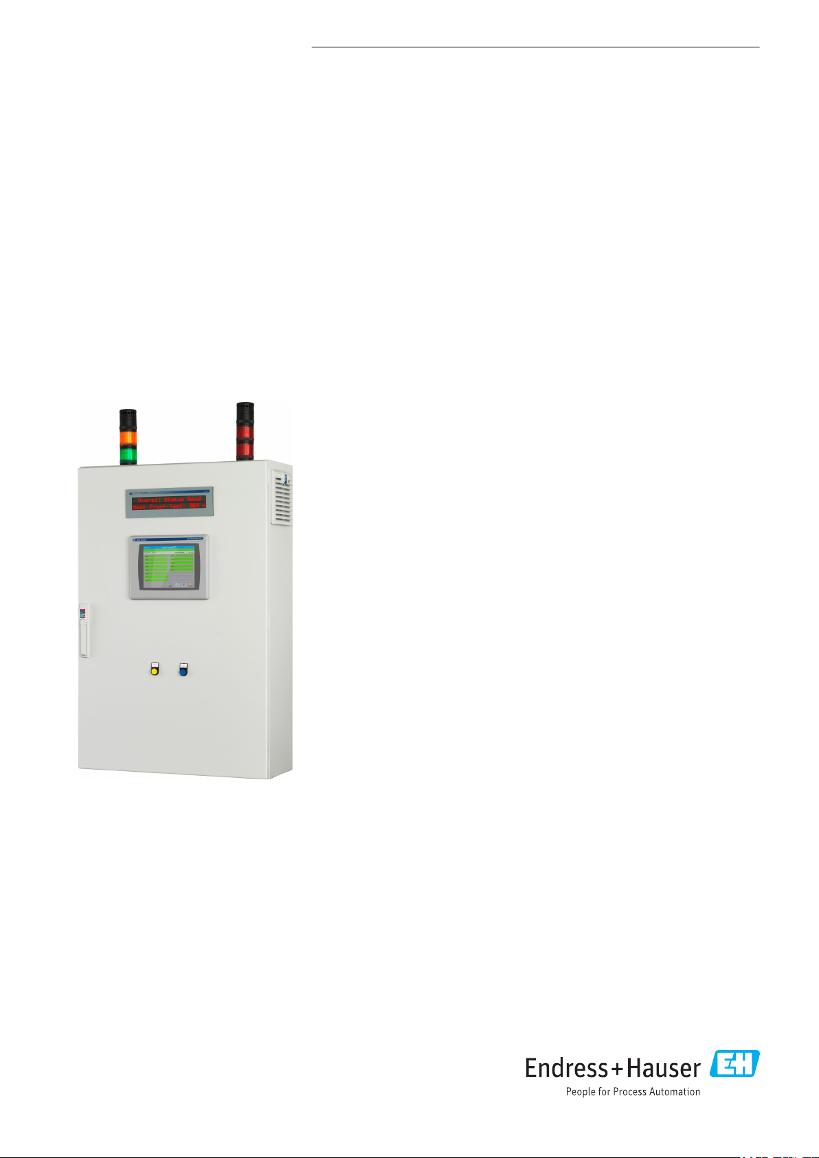
Overfill Prevention System
SOP600
SIL2/SIL3 Tank overfill prevention
For reliable and secure tank overfill prevention
Application
The Overfill Prevention System is type-certified up to SIL3 according to IEC 61511
and meets the requirements of API2350 and WHG (German Water Resources Act).
Two versions of the system are available (automatic and manual) and are designed
for 1 to 16 tanks. If the High-High level is exceeded, a safety relay is disabled or field
signaling is enabled (SIL function). Optionally, the High level can also be monitored
as a warning (for information purposes only, no SIL function). The Overfill
Prevention System features detailed warnings and alarms on the touch panel and on
the optional 2" text display unit, system status indication via stack lights and safetyoriented alarm signaling in the field (optionally AOPS). The text display unit can be
mounted in the cabinet door or in an external housing and helps users to read the
current system status from afar. The system has an automated proof test cycle, which
must be performed periodically to maintain functional safety. A corresponding report
can be printed out on a printer (optional). The system offers an UPS (optionally
AOPS) for 30-minute operation in the event of a power failure.
Your benefits
• Solution with fully independent SIL2/SIL3 certification for maximum trust and
reliability. Certification is performed by independent safety inspectors with
operations worldwide
• Safe investment as the solution is modular, scalable and extensible
• Integrated automated proof testing shortens the time for commissioning and
maintenance
• Detailed warnings and alarms help users to make quick decisions and take
immediate action
• Seamless integration into monitoring systems for remote monitoring via standard
interfaces such as EtherNet/IP or Modbus TCP
• Traceability and transparency with automatic event and user intervention log
• Reduced engineering and commissioning time and lower maintenance costs
Page 2

Table of contents
Document information ....................... 3
Safety symbols ............................... 3
Function and system design ................... 3
Function ................................... 3
System design ................................ 4
Input ..................................... 5
Measured variable ............................. 5
Input signal ................................. 5
Output ................................... 5
Output Signal ................................ 5
Surge voltage resistance ........................ 6
Overvoltage category ........................... 6
Overfill Prevention System SOP600
Power supply .............................. 6
Supply voltage ............................... 6
Electrical connection ........................... 6
Environment ............................... 6
Ambient temperature range ...................... 7
Humidity ................................... 7
Degree of protection ........................... 7
Electromagnetic compatibility (EMC) ................ 7
Mechanical construction ...................... 7
Certificates and approvals .................... 9
CE mark ................................... 9
Ex approval ................................ 10
WHG overfill prevention ........................ 10
Functional safety ............................. 10
Other standards and guidelines ................... 10
Ordering Information ....................... 10
Restrictions ................................ 12
Supplementary documentation ............... 12
Nivotester FailSafe FTL825 ...................... 12
Nivotester FTL325P ........................... 12
Liquiphant FailSafe FTL8x ...................... 12
Liquiphant M FTL5x .......................... 12
Liquiphant M FTL7x .......................... 13
Overfill Prevention System SOP600 ................ 13
2 Endress+Hauser
Page 3
Overfill Prevention System SOP600
DANGER
WARNING
CAUTION
NOTICE
Document information
Safety symbols
Function
Symbol Meaning
DANGER!
This symbol alerts you to a dangerous situation. Failure to avoid this situation will result in
serious or fatal injury.
WARNING!
This symbol alerts you to a dangerous situation. Failure to avoid this situation can result in
serious or fatal injury.
CAUTION!
This symbol alerts you to a dangerous situation. Failure to avoid this situation can result in
minor or medium injury.
NOTE!
This symbol contains information on procedures and other facts which do not result in
personal injury.
Function and system design
The Endress+Hauser Liquiphant (point level switch) transmits the current level (point level exceeded
or not) to the Endress+Hauser Nivotester. If the High-High level is exceeded, the Nivotester opens
the fault-signaling contact which is connected to the safety PLC. The safety PLC detects a level alarm
and switches on the alarm siren and alarm strobe (field signaling MOPS) and/or opens the contact of
the tank-specific safety relay (AOPS). In addition, an alarm message appears on the touch panel and
text display unit, and the alarm is also signaled by the stack lights. If the High level is exceeded, this
only causes a warning message to appear on the touch panel and text display unit, and the stack
lights signal. A safety shutdown is not triggered, however. With the automated proof-testing
feature, the system offers users a simple, time-saving function that guides users through the proof
test on the touch panel. This proof test must be performed periodically (at least once per year) to
guarantee the functional integrity of the safety function. The actuator that is connected to the tankspecific safety relays is not included in the scope of delivery. These are plant-specific and the
responsibility of the plant owner/operator.
There are two kinds of Overfill Prevention System:
• MOPS: The operator stops the supply of media to the tank by closing the corresponding valve or by
switching off the pump. This involves manual intervention in either case. The system alerts the
operator via the alarms on the display and via the signaling equipment installed in the field (siren
and strobe). In the event of a power failure, the integrated UPS ensures that the system remains
fully functional for up to 30 minutes.
• AOPS: The system prevents imminent tank overfill by automatically opening the fault-signaling
contacts, which in turn causes the connected actuator (valve/pump) to close/stop. No manual
intervention is required.
Endress+Hauser 3
Page 4

Overfill Prevention System SOP600
1
3
4
5
6
2
System design
The Overfill Prevention System consists of:
• Cabinet for Overfill Prevention System
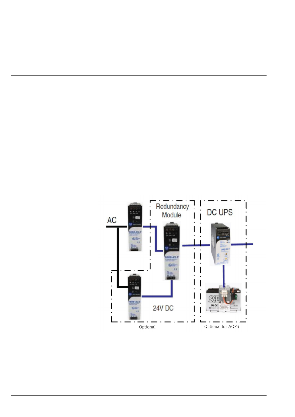
– Power unit (optional: redundant power unit, UPS and battery)
– SIL2 or SIL3 Nivotester (transmitter for Liquiphant)
– SIL3 PLC including input/output modules
– SIL3 safety relay
– Cabinet signaling (stack lights)
– 10" touch panel
– 2" text display unit (optional)
• Field signaling (siren and strobe) optionally for AOPS
• Point level switch (Liquiphant not included in system scope of delivery)
• SIL2 or SIL3 type certificate
– The SIL2/SIL3 type certificate considers the point level switches (Liquiphant), including the
Nivotester, remote I/Os, safety PLC, safety relay (AOPS) or field signaling (MOPS)
– The AOPS does not take the customer's actuator (valve/pump) into consideration
– A project-specific calculation for the corresponding SIL circuit (including actuators) can be
ordered as an option, or can be performed independently by the customer
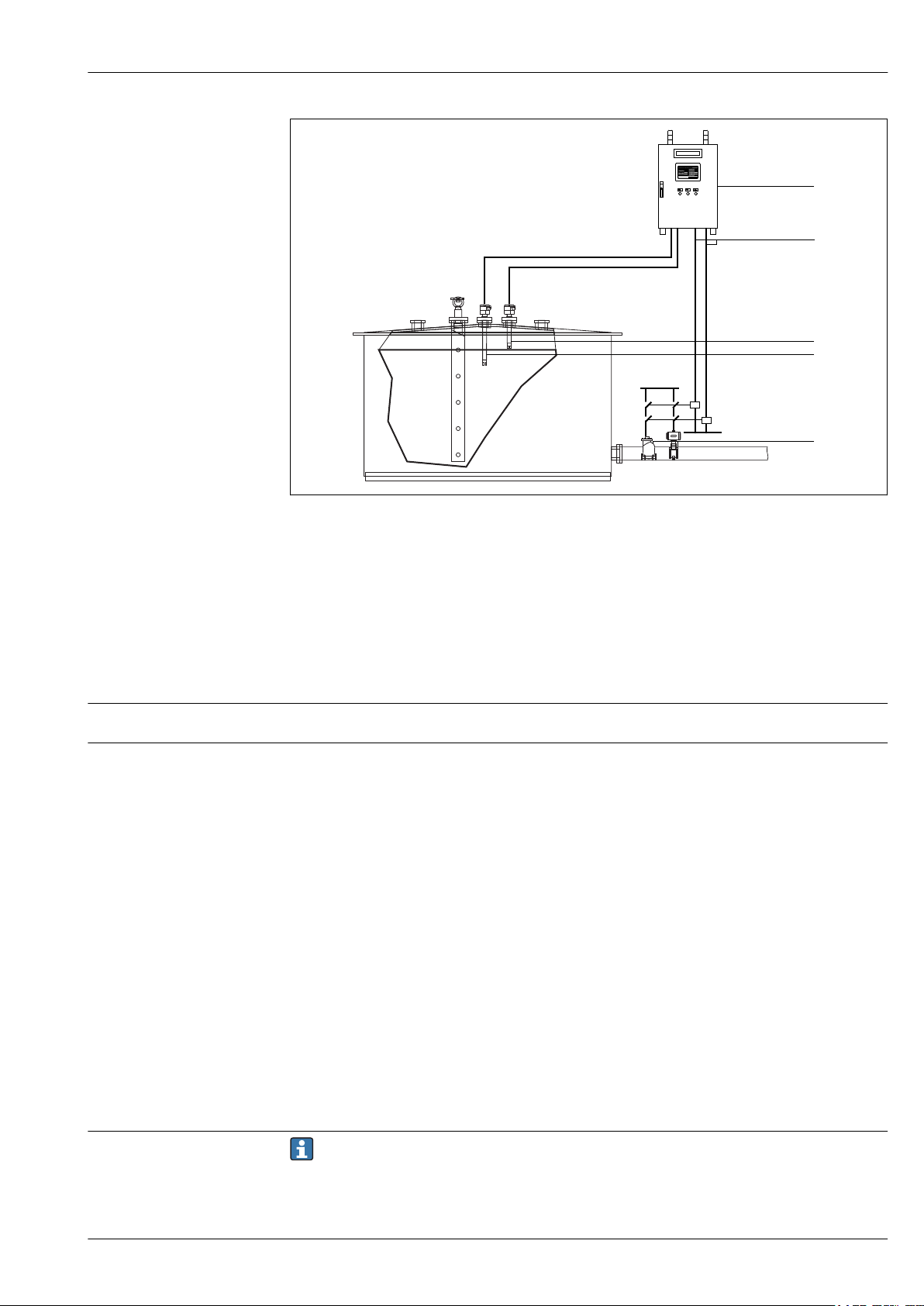
Manual Overfill Prevention System (MOPS)
If overfilling is imminent, the system automatically activates signaling in the control room and
safety-oriented signaling in the field. The operating staff must then manually close or switch off the
actuator (valve/pump).
1 Manual Overfill Prevention System (MOPS) - overview
1 Cabinet for Overfill Prevention System
2 Safety relay output
3 Field signaling
4 Sensor, High-High alarm
5 Sensor, High warning
6 Actuator to be disabled manually
Automated Overfill Prevention System (AOPS)
If overfilling is imminent, the system automatically disables the corresponding safety relay. Any
actuators connected (valve/pump) are closed/switched off automatically.
4 Endress+Hauser
Page 5
Overfill Prevention System SOP600
1
3
4
5
2
Measured variable
Input signal
2 Automated Overfill Prevention System (AOPS) - overview
1 Cabinet for Overfill Prevention System
2 Safety relay output
3 Sensor, High-High alarm
4 Sensor, High warning
5 Automatically disabled actuator
Input
Level
FTL8x (SIL3):
• Connectable point level switches: Liquiphant FailSafe FTL8x with FEL85 electronic insert
• Power supply for point level switch: Nivotester FailSafe FTL825
• Connecting cable between Nivotester and Liquiphant: twin-core, screening is not mandatory
– Max. length: 1 000 m (3 281 ft)
– For detailed information about the electrical connection of the device, see the documentation of
the Liquiphants → 12 used
FTL5x/7x (SIL2):
• Connectable point level switches
– Liquiphant M FTL50 (H), FTL51 (H), FTL51C with FEL57 electronic insert
– Liquiphant S FTL70/71 with FEL57 electronic insert
• Power supply for point level switch: Nivotester FTL325P
• Connecting cable between Nivotester and Liquiphant: twin-core, screening is not mandatory
– Max. length: 1 000 m (3 281 ft)
– For detailed information about the electrical connection of the device, see the documentation of
the Liquiphants → 12 used
Output
Output Signal
Endress+Hauser 5
Output signal only possible with AOPS.
Page 6
Overfill Prevention System SOP600
• Two closing contacts per tank. Protected by 2A fuses (replaceable)
• Min. current/voltage: 10 mA 10 V
• Max. current/voltage:
– UL: C 300
– AC-15: 1.5 A 250 V
– DC-13: 2 A 24 VDC (0.1 Hz)
AC
Surge voltage resistance
Overvoltage category
Supply voltage
2 500 V
(VDE 0110-1)
III
Power supply
Voltage
range
Power
supply
frequency
Power
consumption
Max. backup fuse
90 to 132 VAC (100 to 120 V auto-select input)
180 to 264 VAC (200 to 240 V auto-select input)
50 to 60 Hz(+/- 6%)
Depends on the type of Overfill Prevention System (AOPS, MOPS, SIL2, SIL3, options used etc.) and
the number of tanks
Max. at 230 V: 3 A
Max. at 115 V: 5 A
16 A, tripping characteristic C
Electrical connection
Terminal strip (in cabinet, cable run from below)
Environment
Control cabinet: Indoor installation (max. 25 °C), non-hazardous area
External text display unit: Only indoors, non-hazardous area
6 Endress+Hauser
Page 7
Overfill Prevention System SOP600
Alarm strobe (field signaling): Inside/outside, non-hazardous area
Alarm siren (field signaling): Inside/outside, non-hazardous area
WARNING
L
The loud alarm siren (105dB) can cause
hearing damage.
Only mount sirens outdoors, not in enclosed spaces.
‣
Ambient temperature range
Humidity
Degree of protection
Electromagnetic compatibility (EMC)
Control cabinet: 5 to 25 °C (41 to 77 °F)
External text display unit: 0 to 55 °C (32 to 131 °F)
Alarm strobe (field signaling): –25 to 55 °C (–13 to 131 °F)
Alarm siren (field signaling): –25 to 55 °C (–13 to 131 °F)
Control cabinet: 5 to 85 %RH
External text display unit: 5 to 95 % RH (non-condensating)
Alarm strobe (field signaling): 0 to 90 %RH
Alarm siren (field signaling): 0 to 90 %RH
Control cabinet: IP55 (EN 60529)
External text display unit: IP65 (EN 60529)
Alarm strobe (field signaling): IP 66/IP67 (EN 60529)
Alarm siren (field signaling): IP 66/67 (EN 60529
EC-EMC Directive 2014/30/EU
Mechanical construction
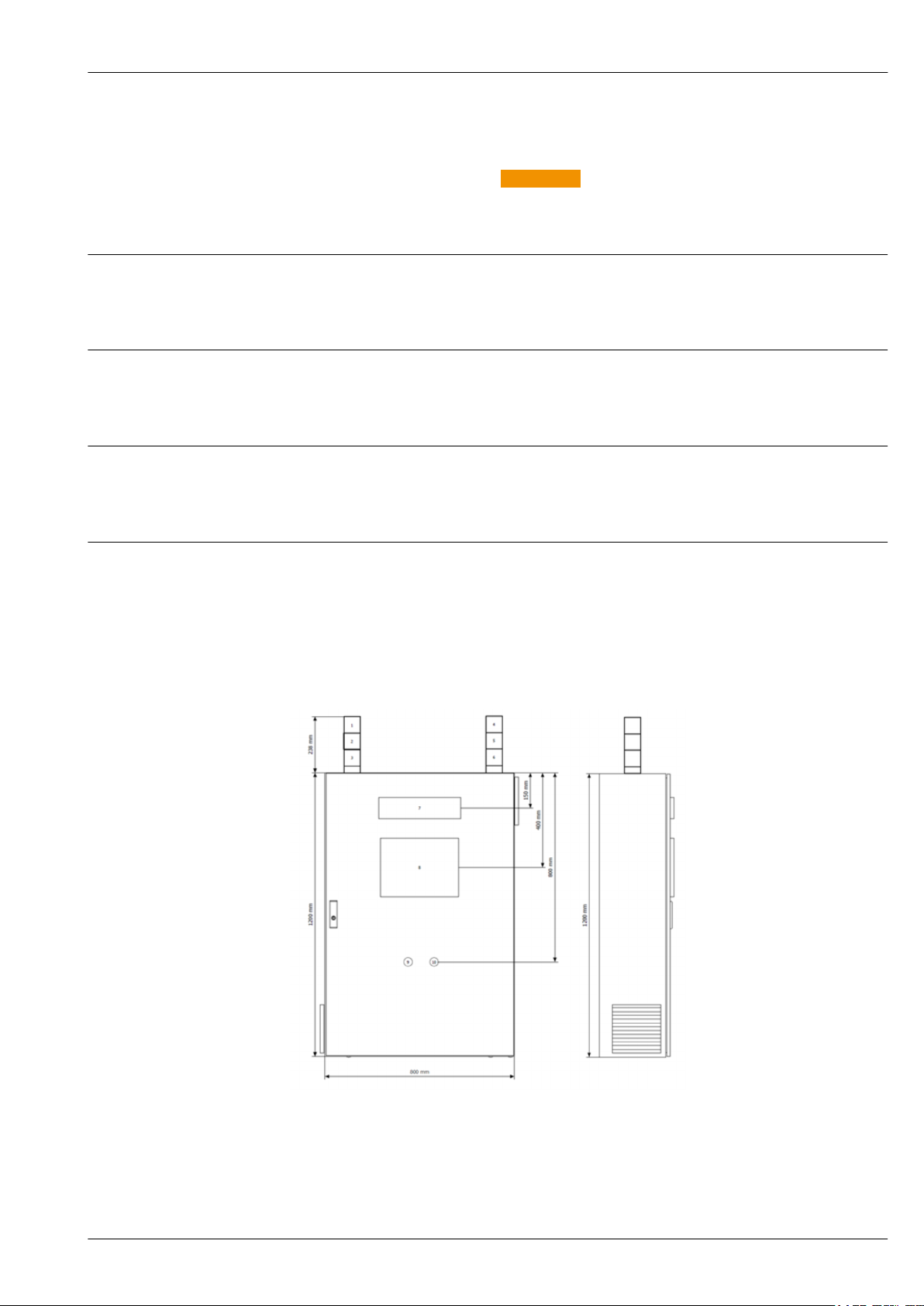
Design, dimensions
3 Example: cabinet for wall mounting (e.g. for 8 tanks)
Endress+Hauser 7
Page 8
Overfill Prevention System SOP600
A0031798
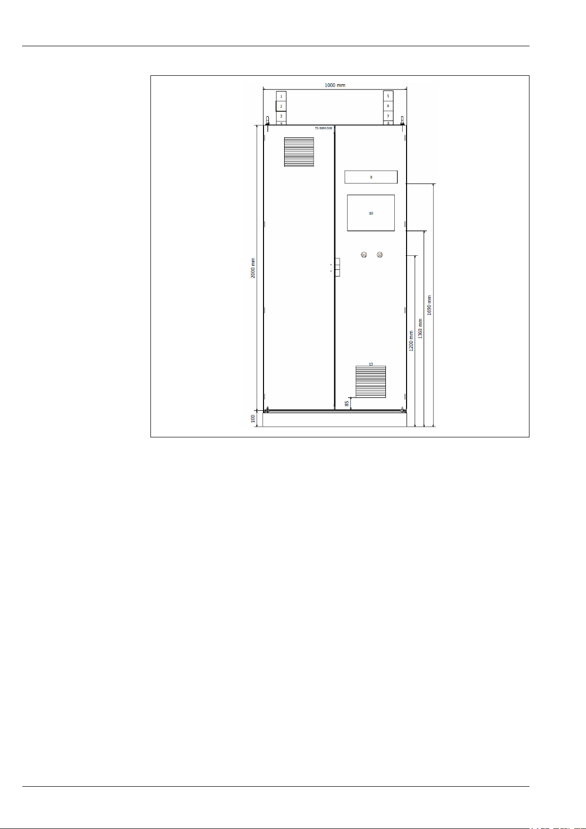
4 Example: freestanding cabinet (e.g. for 16 tanks)
The dimensions of the cabinet depend on the type of Overfill Prevention System (AOPS, MOPS, SIL2,
SIL3, options used etc.) and the number of tanks:
• Cabinet for 8 tanks:
800x1200x300 (BxHxD in mm), for wall mounting + approx. 250 mm height for the signal lamps
• Cabinet for 12 tanks:
1000x1200x300 (BxHxD in mm, double-door), for wall mounting + approx. 250 mm height for
the signal lamps
• Cabinet for 12 tanks:
800x2000x400 (BxHxD in mm), freestanding + approx. 250 mm height for the signal lamps +
100 mm height for the base
• Cabinet for 16 tanks:
1000x2000x400 (BxHxD in mm, double-door), freestanding + approx. 250mm height for the
signal lamps + 100 mm height for the base
8 Endress+Hauser
Page 9
Overfill Prevention System SOP600
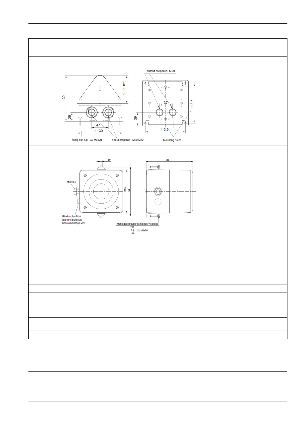
Housing for
external text
display unit
Alarm strobe
(field signaling)
Alarm siren
(field signaling)
400x200x80 (BxHxD in mm)
150x150x143 (BxHxD in mm)
130x130x130 (BxHxD in mm)
Weight The weight of the cabinet depends on the type of Overfill Prevention System (AOPS, MOPS, SIL2, SIL3, options used etc.) and the
number of tanks:
• Approx. 120 kg for cabinet measuring 800x1200x300 (BxHxD in mmm)
• Approx. 150 kg for cabinet measuring 1000x1200x300 (BxHxD in mmm)
• Approx. 180 kg for cabinet measuring 800x2000x400 (BxHxD in mmm)
• Approx. 250 kg for cabinet measuring 1000x2000x400 (BxHxD in mmm)
Material • Sheet steel, 1.5 mm
• Dipcoat primed, RAL 7035
Terminals Different types of terminals (standard, multi-tier and terminal blocks) are mounted on the underside of the mounting plate.
Operating
concept
Operating
element
Display element 2" text display unit (optional)
General:
Local configuration and operation (including the proof testing procedure) 10" touch panel on the cabinet door
MOPS:
If a High-High level alarm occurs, the operator must manually switch off the specific valve or the pump of the plant.
10" touch panel
Certificates and approvals
CE mark
The devices have been designed and tested according to the safety requirements in such a way that
they are delivered to the customer in perfect operating condition. The devices comply with the valid
standards and regulations listed in the EC Declaration of Conformity and therefore meet the legal
Endress+Hauser 9
Page 10
Overfill Prevention System SOP600
requirements of the EC Directive. Endress+Hauser confirms the conformity of the devices by affixing
to them the CE mark.
Ex approval
WHG overfill prevention
Functional safety
Other standards and guidelines
The cabinet, the text display unit and the outside signaling unit must be mounted in a nonhazardous area. The Liquiphants can be mounted in hazardous areas. Information about currently
available hazardous area versions (IECEx, ATEX Ex ia; TIIS; NEPSI; FM ist; CSA IS) depend on the
Liquiphants used.
• Overfill detection system: Z-65-11-507
• Leak detection system: Z-65-40-508
For safety functions in conjunction with FEL85 to SIL3 (MAX detection), see the Functional Safety
Manual (SIL) SD00350F/00/EN.
For safety functions in conjunction with FEL57 to SIL2 (MAX detection), see the Functional Safety
Manual (SIL) SD00111F/00/EN
• EC Low Voltage Directive 2014/35/EU
• IEC/EN 60204-1
Safety of Machinery - Electrical Equipment of Machines
• IEC 61508
Functional Safety of Electrical/Electronic/Programmable Electronic Safety-related Systems (E/E/
PES)
• IEC 61511:2003
Functional safety
Safety Instrumented Systems for the Process Industry Sector, 2003
Ordering Information
Order code:
SOP600 - 010 020 030 040 050 060 070 080 090 510 570 610
Feature Description Option model
010 System A Automated Overfill Prevention System
(AOPS)
M Manual Overfill Prevention System (MOPS)
020 Safety Integrity Level 2 2 (only High-High level SIL certified)
3 3 (only High-High level SIL certified)
9 Special version, TSP-no. to be spec.
030 Max. number of tanks A11 4 (High-High level), AOPS
A12 8 (High-High level), AOPS
A13 12 (High-High level), AOPS
A14 16 (High-High level), AOPS
A21 4 (High + High-High level), AOPS
A22 8 (High + High-High level), AOPS
A23 12 (High + High-High level), AOPS
A24 16 (High + High-High level), AOPS
M11 4 (High-High level), MOPS
M12 8 (High-High level), MOPS
M13 12 (High-High level), MOPS
M14 16 (High-High level), MOPS
10 Endress+Hauser
Page 11
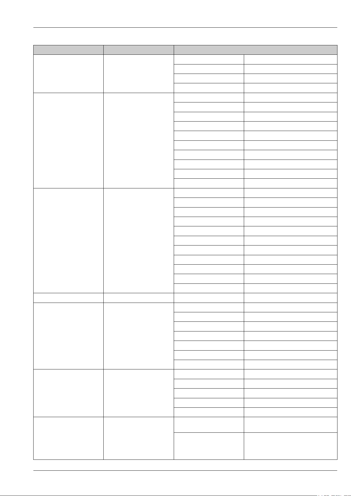
Overfill Prevention System SOP600
Feature Description Option model
M21 4 (High + High-High level), MOPS
M22 8 (High + High-High level), MOPS
M23 12 (High + High-High level), MOPS
M24 16 (High + High-High level), MOPS
040 High-High level (SIL certified) AA FTL325P-H1E1 (ATEX/IEC Ex), SIL2
AB FTL325P-N1E1 (NEPSI), SIL2
AC FTL325P-P1E1 (FM), SIL2
AD FTL325P-T1E1 (CSA), SIL2
BA FTL825-AA3E4 (NEx), SIL3
BB FTL825-CA3E4 (CSA), SIL3
BC FTL825-N23E4 (NEPSI), SIL3
BD FTL825-8B3E4 (ATEX / IECEx), SIL3
BE FTL825-8C3E4 (FM / CSA), SIL3
YY Special version, TSP-no. to be spec.
050 High level (not SIL certified) AA W/o
AB FTL325P-H1E1 (ATEX / IEC Ex)
AC FTL325P-N1E1 (NEPSI)
AD FTL325P-P1E1 (FM)
AE FTL325P-T1E1 (CSA)
BA FTL825-AA3E4 (NEx)
BB FTL825-CA3E4 (CSA)
BC FTL825-N23E4 (NEPSI)
BD FTL825-8B3E4 (ATEX / IECEx)
BE FTL825-8C3E4 (FM / CSA)
YY Special version, TSP-no. to be spec.
060 Analog signal 0 W/o
070 Power unit A Redundant + internal UPS
B Single + internal UPS
E Redundant; without UPS
F Single; without UPS
J Redundant + external (customer) UPS
K Single + external (customer) UPS
Y Special version, TSP-no. to be spec.
080 Control cabinet 1 BxHxD (800x1200x300), sheet steel
2 BxHxD (1000x1200x300), sheet steel
3 BxHxD (800x2000x400), sheet steel
4 BxHxD (1000x2000x400), sheet steel
9 Special version, TSP-no. to be spec.
090 System approval 0 SIL type approval in accordance with IEC
61511 (excl. valves or contactors/pumps)
1 Specific SIL circuit calculation (incl. valve or
contactors/pumps)
Safety data sheets from actuator needed
from customer
Endress+Hauser 11
Page 12
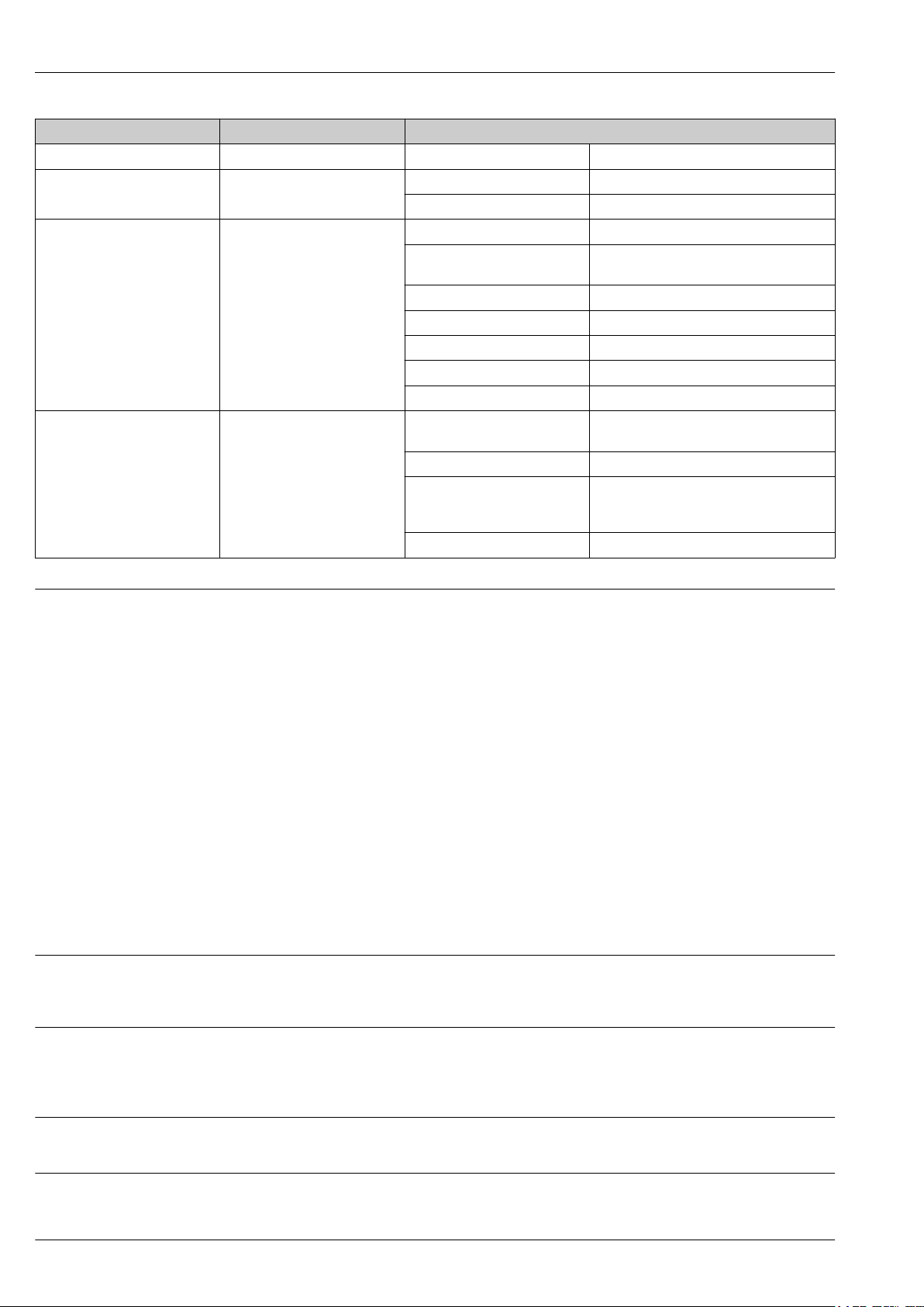
Overfill Prevention System SOP600
Feature Description Option model
9 Special version, TSP-no. to be spec.
510 Interface B1 Modbus TCP (slave)
B2 Ethernet/IP
570 Services I1 Delivery of internal FAT report & photos
I2 Internal FAT report & photos + 10%
customer FAT
IA Customer FAT (100% test, 1-4 tanks)
IB Customer FAT (100% test, 5-8 tanks)
IC Customer FAT (100% test, 9-12 tanks)
ID Customer FAT (100% test, 13-16 tanks)
I9 Special version, TSP-no. to be spec.
610 Accessory mounted N1 Remote maintenance modem mbConnect
(MDH834)
N2 Text display unit in cabinet door
N3 Text display unit in own housing (BxHxD;
400x200x80, sheet steel); display IP55
(indoor only)
N4 SIL siren + SIL strobe (not relevant for SIL)
Restrictions
Nivotester FailSafe FTL825
Nivotester FTL325P
030: Axx only for AOPS (010 = A); Mxx only for MOPS (010 = M)
040: Ax only with SIL2 (020 = 2)
050: AA only available with A11-A14 + M11-M14 (030)
All others only with A21-A24 + M21-M24 (030)
060: Possible future option
070: E, F, K only with AOPS
080: 1 only available with A11-13 + A21-22 + M11-13 + M21-22 (030)
2 only available with A11-23 + M11-23 (030)
3 only available with A11-13 + A21-22 + M11-13 + M21-22 (030)
Other configurations on request
570: IA only available with A11 + A21 + M11 + M21 (030)
IB only available with A12 + A22 + M12+ M22 (030)
IC only available with A13 + A23 + M13+ M23 (030)
ID only available with A11 + A21 + M11 + M21 (030)
610: N4 only available with AOPS (010 = A)
Supplementary documentation
• Technical Information TI01027F/00/EN
• Operating Instructions BA01038F/00/EN
• Functional Safety Manual (SIL) SD00350F/00/EN
• Technical Information TI00350F/00/EN
• Brief Operating Instructions KA00167F/00/F/EN
• Functional Safety Manual (SIL) SD00111F/00/EN
• Functional Safety Manual (SIL) SD01508F/00/EN
Liquiphant FailSafe FTL8x
• Technical Information TI01026F/00/EN
• Operating Instructions BA01037F/00/EN
Liquiphant M FTL5x
• Technical Information TI00328F/00/EN
• Brief Operating Instructions KA00143F/00/EN
12 Endress+Hauser
Page 13

Overfill Prevention System SOP600
Liquiphant M FTL7x
Overfill Prevention System
SOP600
• Technical Information TI00354F/00/EN
• Brief Operating Instructions KA00143F/00/EN
• Operating Instructions BA01587S/04/EN
• Functional Safety Manual (SIL) SD01599S/04/EN
Endress+Hauser 13
Page 14

Page 15

Page 16

www.addresses.endress.com
 Loading...