

Page 1
Technical Information
Soliphant T FTM260
Level limit switch
Cost-effective vibration limit switch for fine-grained solids
Application
Soliphant is a rugged level limit switch for use
in silos containing fine-grained and powdery solids
(up to 10 mm).
Its design and constructional materials also make it
suitable for foodstuff applications.
Examples:
grain, flour, milk powder, cocoa, sugar, animal feed,
washing powders, dyes, chalk, plaster, cement, plastic
granulates
Your benefits
• No calibration:
quick and low-cost start-up
• Insensitive to build-up:
maintenance-free
• No mechanical moving parts:
no wear, long operating life
• Various electronic inserts:
optimum adaptability to the plant process
• External switching status:
simple control
TI238F/00/en
Page 2

Table of contest
Function and system design. . . . . . . . . . . . . . . . . . . . . 3
Measuring principle . . . . . . . . . . . . . . . . . . . . . . . . . . . . . . . . . . . 3
Measuring system . . . . . . . . . . . . . . . . . . . . . . . . . . . . . . . . . . . . . 3
Output . . . . . . . . . . . . . . . . . . . . . . . . . . . . . . . . . . . . . 4
Signal on alarm . . . . . . . . . . . . . . . . . . . . . . . . . . . . . . . . . . . . . . 4
Connectable load . . . . . . . . . . . . . . . . . . . . . . . . . . . . . . . . . . . . . 4
Switch behaviour . . . . . . . . . . . . . . . . . . . . . . . . . . . . . . . . . . . . . 4
Fail-safe mode . . . . . . . . . . . . . . . . . . . . . . . . . . . . . . . . . . . . . . . 4
Power supply . . . . . . . . . . . . . . . . . . . . . . . . . . . . . . . . 5
Electrical connection . . . . . . . . . . . . . . . . . . . . . . . . . . . . . . . . . . 5
Supply voltage . . . . . . . . . . . . . . . . . . . . . . . . . . . . . . . . . . . . . . . 5
Installation. . . . . . . . . . . . . . . . . . . . . . . . . . . . . . . . . . 6
Installation instructions . . . . . . . . . . . . . . . . . . . . . . . . . . . . . . . . . 6
Soliphant T FTM260
Environment . . . . . . . . . . . . . . . . . . . . . . . . . . . . . . . . 7
Ambient temperature . . . . . . . . . . . . . . . . . . . . . . . . . . . . . . . . . . 7
Storage temperature . . . . . . . . . . . . . . . . . . . . . . . . . . . . . . . . . . . 7
Climate class . . . . . . . . . . . . . . . . . . . . . . . . . . . . . . . . . . . . . . . . 7
Degree of protection . . . . . . . . . . . . . . . . . . . . . . . . . . . . . . . . . . . 7
Mechanical load on fork . . . . . . . . . . . . . . . . . . . . . . . . . . . . . . . . 7
Electromagnetic compatibility . . . . . . . . . . . . . . . . . . . . . . . . . . . . 7
Process . . . . . . . . . . . . . . . . . . . . . . . . . . . . . . . . . . . . 7
Medium temperature . . . . . . . . . . . . . . . . . . . . . . . . . . . . . . . . . . 7
Temperature diagram . . . . . . . . . . . . . . . . . . . . . . . . . . . . . . . . . . 7
Bulk density of material . . . . . . . . . . . . . . . . . . . . . . . . . . . . . . . . 7
Grain size of material . . . . . . . . . . . . . . . . . . . . . . . . . . . . . . . . . . 7
Operating pressure pe . . . . . . . . . . . . . . . . . . . . . . . . . . . . . . . . . . 7
Mechanical construction . . . . . . . . . . . . . . . . . . . . . . . 8
Design, dimensions . . . . . . . . . . . . . . . . . . . . . . . . . . . . . . . . . . . 8
Weight . . . . . . . . . . . . . . . . . . . . . . . . . . . . . . . . . . . . . . . . . . . . . 8
Material . . . . . . . . . . . . . . . . . . . . . . . . . . . . . . . . . . . . . . . . . . . . 8
Process connection . . . . . . . . . . . . . . . . . . . . . . . . . . . . . . . . . . . . 8
Human interface . . . . . . . . . . . . . . . . . . . . . . . . . . . . . 9
Display elements, operating elements . . . . . . . . . . . . . . . . . . . . . . 9
Ordering information. . . . . . . . . . . . . . . . . . . . . . . . . . 9
Product structure . . . . . . . . . . . . . . . . . . . . . . . . . . . . . . . . . . . . . 9
Supplementary Documentation . . . . . . . . . . . . . . . . . . 9
Technical Information . . . . . . . . . . . . . . . . . . . . . . . . . . . . . . . . . 9
2
Endress+Hauser
Page 3
Soliphant T FTM260
Function and system design
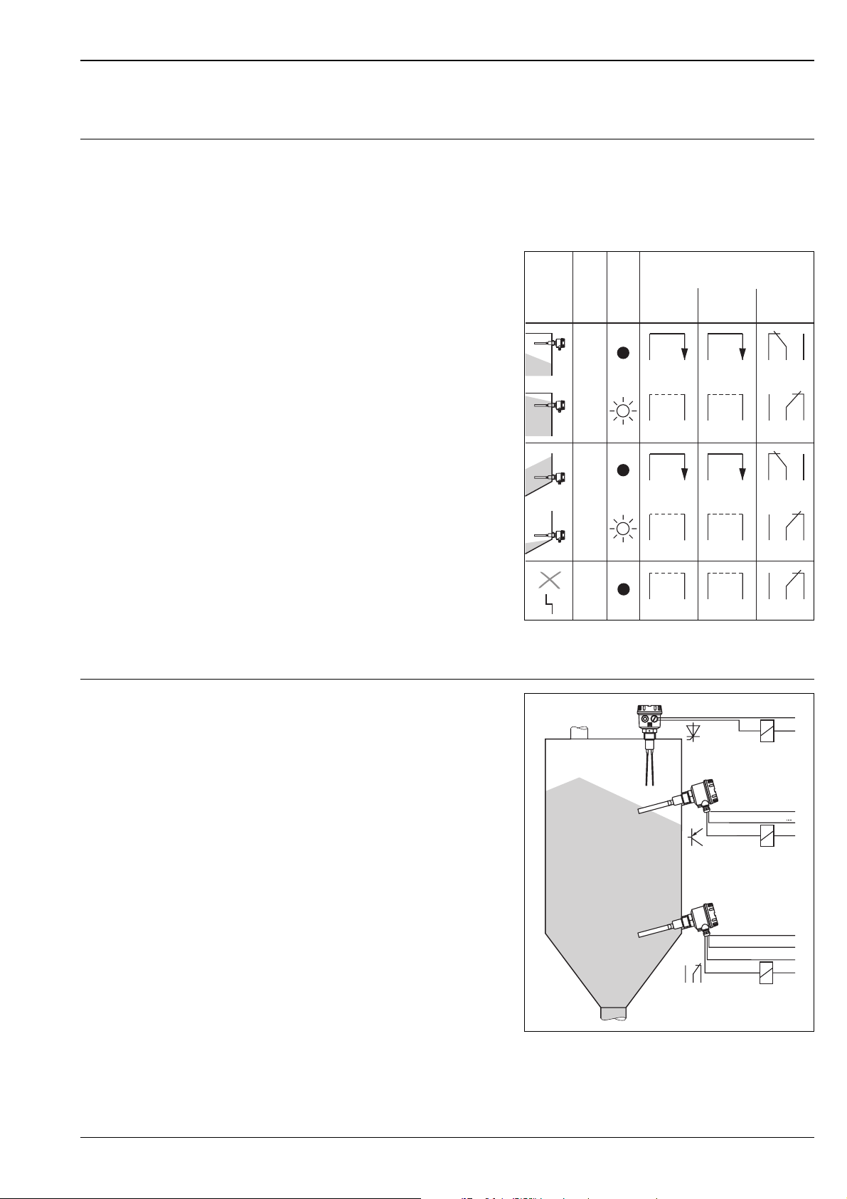
Measuring principle The symmetrical vibrating fork is excited to its resonant frequency. Vibration characteristics change when the
fork is submerged in solid material. The change is registered by the electronics which actuate an electronic
switch or relay.
The tip of the Soliphant fork is particularly sensitive, while the base of the fork is completely insensitive.
This enables solids of very low density to be detected even with material build-up on the vessel walls.
The function of the electronic switch or relay
FEM31
Electronic inserts
FEM32
L+ +
1
2
L+
1
2
FEM34
3
3
3
4
5
3
4
5
and the LED is dependent on both the level and
fail-safe mode selected
Level
Fail-safe
Max.
mode
LED
1
1
Measuring system
L+
+
1
1
2
3
3
4
Min.
L+
1
1
2
3
3
4
U
1
L+
2
Soliphant FTM260 can be operated in both minimum or maximum fail-safe mode, i.e. the electronic switch
opens or the relay de-energises on reaching the limit value, on a fault or on a loss of power.
Soliphant FTM260 is a compact limit switch to
which miniature contactors, solenoid valves
and programmable logic controllers (PLC) can be
directly connected.
31
4
L00-FTM260xx-15-06-xx-de-001
U
~
U–
+
5
5
53
U–
~
L00-FTM260xx-14-06-xx-xx-001
Endress+Hauser 3
Page 4

Output
Signal on alarm Output open or relay de-energised
Connectable load •with FEM31
(The load is switched directly via a thyristor in the power circuit)
Short-term (40 ms) max. 1.5 A, max. 375 VA at 250 V or max. 36 VA at 24 V
(no short circuit protection),
continuous max. 87 VA at 253 V, max. 8.4 VA at 24 V,
min. 2.5 VA at 253 V (10 mA), min. 0.5 VA at 24 V (20 mA);
Voltage drop across FEM 31 max. 12 V at load current >10 mA
(max. 10 V at load current >20 mA);
Quiescent current max. 3.8 mA with open thyristor
•with FEM32
(The load is switched via a transistor and separate PNP connection)
Short-term (1 s) max. 1 A, max. 55 V
(cyclic overload and short-circuit protection),
continuous max. 350 mA,
max. 0.5 µF at 55 V, max. 1.0 µF at 24 V;
Residual voltage <3 V (with closed transistor);
Residual current <100 µA (with open transistor)
•with FEM34
(The load switched via a potential-free changeover contact)
I~ max. 6 A, U~ max. 253 V,
P~ max. 1500 VA, cos ϕ = 1, P~ max. 750 VA, cos ϕ > 0.7;
I– max. 6 A bis 30 V, I– max. 0.2 A to 125 V;
Additional switching delay 0.3 s
Soliphant T FTM260
Switch behaviour approx. 0.6 s when covered,
approx. 1.4 s when free
Fail-safe mode Minimum or maximum fail-safe mode, switchable
4 Endress+Hauser
Page 5
Soliphant T FTM260
Power supply
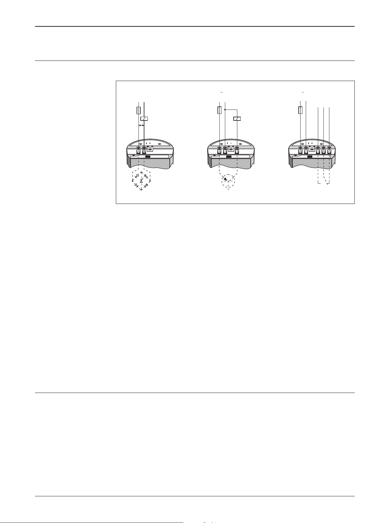
Electrical connection Screw terminals on electronic insert for max. 2.5 mm2 wire in end sleeve A 2.5 - 7 to DIN 46 228
!
1A
U~
L1 N
19...253 V
12
FEM 31
U– 10...55 V
L+
0.5 A
12 3
FEM 32
L–
–
(+)
0.2 A
12
U~ 19...253 V
U– 19...200 V
L1 N
aur
345
FEM 34
L00-FTM260xx-04-05-xx-xx-002
Electronic insert FEM31
Two-wire AC connection (thyristor)
Note!
Always connect in series with the load!
Check the following:
• the residual current in blocked state (up to 3.8 mA)
• that for low voltage
– the voltage drop across the load such so that the minimum terminal voltage at the electronic insert (19 V)
when blocked is not too low.
– the voltage drop across the electronic insert when open is observed (up to 12 V).
• that a relay cannot de-energise with a retaining current below 3.8 mA.
If this is the case, a resistor should be connected parallel to the relay.
Electronic insert FEM32
Three-wire DC connection (transistor, PNP)
Designed to be connected to programmable logic controllers (PLC).
Positive signal at switching output of the electronic insert (PNP).
Electronic insert FEM34
Universal connection (relay, potential-free changeover contact)
Potential-free changeover contact.
Supply voltage •Output with FEM31
Voltage at Terminals 1 and 2: 19...253 V, 50/60 Hz,
Current consumption (stand-by) max. 3.8 mA
•Output with FEM32
10...55 V, ripple max. 1.7 V, 0...400 Hz,
Current consumption max. 15 mA, protection against reverse polarity
•Output with FEM34
AC 19...253 V, 16...60 Hz or DC 19...200 V,
Current consumption max. 7 mA
Endress+Hauser 5
Page 6
Installation
Soliphant T FTM260
!
Installation instructions Mounting location
Note!
All dimensions in mm
100 mm = 3.94 in
b.
c.
a.
e.
~20°
~250
~200
~200
f.
g.
d.
L00-FTM260xx-11-06-xx-xx-001
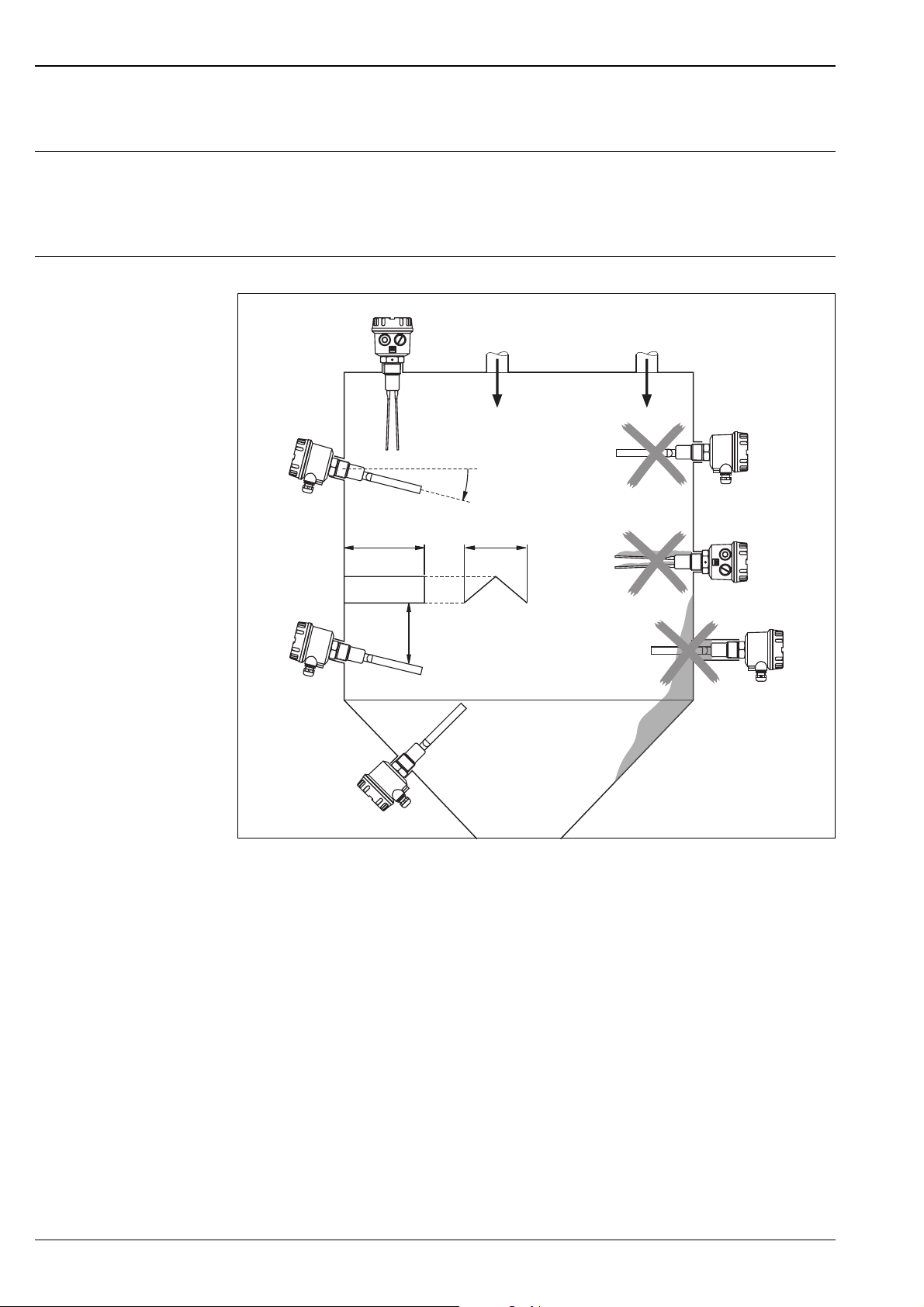
Left: correct
a. vertically mounted from above; any fork position
b. laterally mounted with fork angled slightly downwards, nozzle length max. 60 mm
c. with roof (length approx. 250 mm, width approx. 200 mm) to protect against collapsing mounds
d. in discharge hopper
Right: incorrect
e. in filling curtain
f. false orientation of the fork (high load on the wide surface of the fork caused by discharging material;
malfunction due to residual material)
g. mounting nozzle too long
Orientation
The Soliphant FTM260 may be installed at any orientation in a vessel containing bulk solids.
6 Endress+Hauser
Page 7
Soliphant T FTM260
Environment
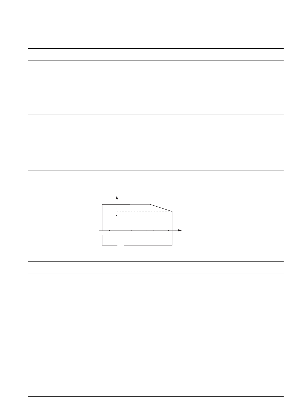
Ambient temperature –40 °C...+70 °C (–40°F…+160°F), see also "Temperature diagram"
Storage temperature –40 °C...+85 °C (–40°F…+185°F)
Climate class Climatic protection according to IEC 68, Part 2-38, Fig. 2a
Degree of protection IP66 according to DIN 40050
Mechanical load on fork 600 N,
lateral (on fine edges of tines), static
Electromagnetic compatibility Interference Emission to EN 61326, Electrical Equipment Class B
Interference Immunity to EN 61326, Annex A (Industrial) and NAMUR Recommendation NE 21 (EMC)
Process
Medium temperature –40 °C...+150 °C (–40°F…+300°F), see also "Temperature diagram"
Temperature diagram
Permissible values for ambient temperature T
at housing are dependent on the operating temperature TB
U
in the silo:
T
U
°C
80
60
40
20
–20 100 120 140 1608060
–40
x °C = (1.8 x + 32)°F
–20
–40
40
20
T
B
°C
Bulk density of material min. 100 g/l
Grain size of material up to 10 mm (0.4 in)
Operating pressure p
e
–1 bar...+16 bar (–14.5…+230 psi), burst pressure >40 bar
L00-FTM260xx-05-06-xx-xx-001
Endress+Hauser 7
Page 8
Mechanical construction
Soliphant T FTM260
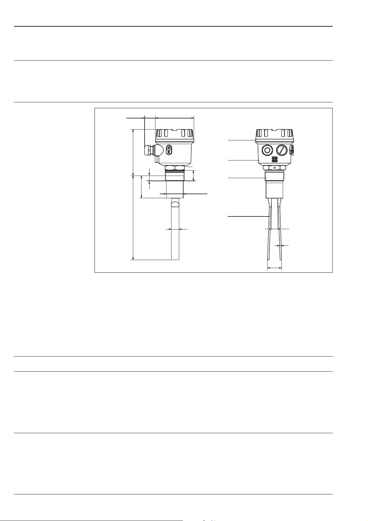
Design, dimensions
!
Note!
All dimensions in mm
100 mm = 3.94 in
~115
~216
~60
ø95max. 30
a
b
ø max. 43
20
50 AF
28
c
d
15
4
15
a. The transparent cover shows the LED which indicates the switching mode
b. Plastic housing,
Protection IP66, with cable gland versions
c. Process connections:
– R 1½, DIN 2999, (tapered)
in stainless steel
– 1½" NPT, (tapered)
d. Vibrating fork in solid stainless steel with high mechanical resistance to lateral loads
Weight approx. 1.1 kg with electronic insert
Material • Process connection and vibrating fork: stainless steel AISI 304 (1.4301)
and AISI 316Ti (1.4571)
• Housing (F14): polyester
• Transparent cover: polyamide
• O-ring seal: EPDM
• Cable gland M20x1.5: polyamide with Neoprene-CR seal
Process connection Tapered thread R 1½, DIN 2999;
Tapered thread 1½" NPT
~40
L00-FTM260xx-06-05-xx-de-001
8 Endress+Hauser
Page 9
Soliphant T FTM260
Human interface
Display elements, operating elements
Product structure
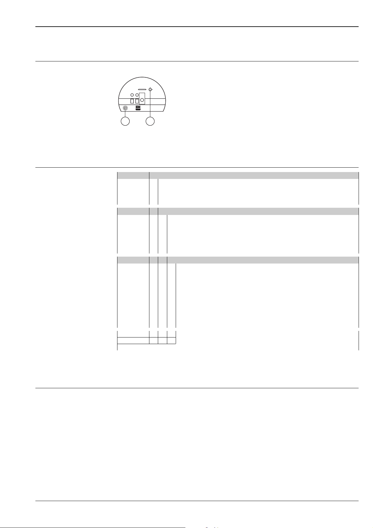
The plug-in electronic insert can be easily replaced with another electronic insert - without calibration
FEM..
Min
Max
E = LED indicates switching status
EF
L00-FTM260xx-04-05-xx-xx-001
F = Fail-safe mode is selected by turning a switch
Ordering information
20 Process Connection
G Thread DIN2999 R1½ 304
N Thread ANSI NPT1½ 304
YSpecial version
30 Electronics; Output
Y Special version
1 FEM31 2-wire 19...253 V AC
2 FEM32 3-wire PNP 10...55 V DC
4 FEM34 relay 19...253 V AC/200 V DC
8not selected
40 Housing; Cable Entry
B F14 Polyester NEMA4X thread NPT½
C F14 Polyester IP66 thread G½
D F14 Polyester IP66 gland M20
R F14 Polyester IP66 thread NPT½
S F14 Polyester IP66 gland M20
YSpecial version
FTM260 Complete product designation
Supplementary Documentation
Technical Information General information on EMC
TI241F/00
CSA GP, non transparent cover
CSA GP, non transparent cover
Endress+Hauser 9
Page 10

Soliphant T FTM260
10 Endress+Hauser
Page 11

Soliphant T FTM260
Endress+Hauser 11
Page 12

Soliphant T FTM260
International Head Quarter
Endress+Hauser
GmbH+Co. KG
Instruments International
Colmarer Str. 6
79576 Weil am Rhein
Deutschland
Tel. +49 76 21 9 75 02
Fax +49 76 21 9 75 34 5
www.endress.com
[email protected]
TI238F/00/en/11.04
SL/FM+SGML6.0 ProMoDo
 Loading...