

Page 1
TI00389F/00/EN/13.16
71346118
Products Solutions Services
Technical Information
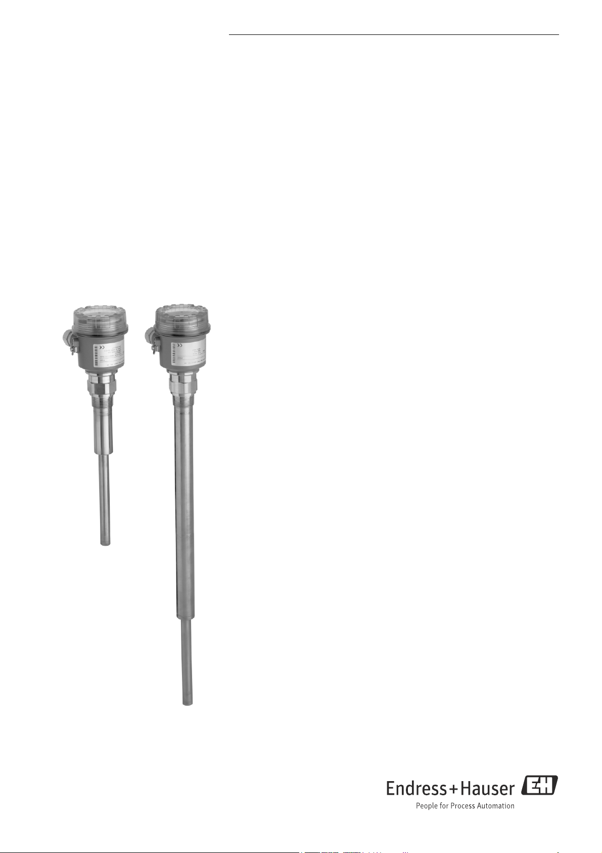
Soliphant T FTM20, FTM21
Vibronic
Robust point level switch for bulk solids,
also for dust incendive hazard areas
Application
Soliphant T is a robust point level switch for silos with fine-grained or coarse-grained,
non-fluidised bulk solids.
The various designs means the device has a wide range of applications. Certificates are
also available for use in dust incendive hazard areas.
FTM20 compact design 250 mm (10 in) as vibrating rod for installation in any direction
FTM21 vibrating rod with extension pipe 500 mm, 1000 mm, 1500 mm (20 in, 40 in, 60 in)
for installation in any direction
Typical applications: cereals, coffee beans, sugar, animal feed, rice, detergents, dye
powder, chalk, gypsum, cement, sand, plastic granules
Your benefits
• No calibration: easy commissioning (plug and play)
• Insensitive to build-up: maintenance-free operation
• No mechanically moving parts: no wear, long operating life
• Sensor material 316L: hardly any abrasion even with building materials
• F16 plastic housing with cover with sight glass: switch status visible from outside
• F18 aluminium housing also available
• Insensitive to external vibration and flow noises
• Also available with explosion protection ATEX II 1/3 D, FM or CSA approval
Page 2

Table of contents
Soliphant T FTM20, FTM21
Function and system design. . . . . . . . . . . . . . . . . . . . . 3
Measuring principle . . . . . . . . . . . . . . . . . . . . . . . . . . . . . . . . . . . 3
Measuring system . . . . . . . . . . . . . . . . . . . . . . . . . . . . . . . . . . . . . 3
Cable specifications . . . . . . . . . . . . . . . . . . . . . . . . . . . 4
Temperature resistance . . . . . . . . . . . . . . . . . . . . . . . . . . . . . . . . . 4
Cable entries . . . . . . . . . . . . . . . . . . . . . . . . . . . . . . . . . . . . . . . . 4
Input . . . . . . . . . . . . . . . . . . . . . . . . . . . . . . . . . . . . . . 4
Measured variable . . . . . . . . . . . . . . . . . . . . . . . . . . . . . . . . . . . . 4
Measuring range (application) . . . . . . . . . . . . . . . . . . . . . . . . . . . . 4
Input signal . . . . . . . . . . . . . . . . . . . . . . . . . . . . . . . . . . . . . . . . . 4
Measuring frequency . . . . . . . . . . . . . . . . . . . . . . . . . . . . . . . . . . 4
Output . . . . . . . . . . . . . . . . . . . . . . . . . . . . . . . . . . . . . 4
Galvanic isolation . . . . . . . . . . . . . . . . . . . . . . . . . . . . . . . . . . . . . 4
Switch behaviour . . . . . . . . . . . . . . . . . . . . . . . . . . . . . . . . . . . . 4
Power-on behaviour . . . . . . . . . . . . . . . . . . . . . . . . . . . . . . . . . . . 4
Fail-safe mode . . . . . . . . . . . . . . . . . . . . . . . . . . . . . . . . . . . . . . . 4
Switching delay . . . . . . . . . . . . . . . . . . . . . . . . . . . . . . . . . . . . . . 4
Ex specifications . . . . . . . . . . . . . . . . . . . . . . . . . . . . . . . . . . . . . . 4
FEM22 electronic insert (DC PNP) . . . . . . . . . . . . . . . 5
Power supply . . . . . . . . . . . . . . . . . . . . . . . . . . . . . . . . . . . . . . . . 5
Electrical connection . . . . . . . . . . . . . . . . . . . . . . . . . . . . . . . . . . 5
Output signal . . . . . . . . . . . . . . . . . . . . . . . . . . . . . . . . . . . . . . . . 5
Signal on alarm . . . . . . . . . . . . . . . . . . . . . . . . . . . . . . . . . . . . . . 5
Connectable load . . . . . . . . . . . . . . . . . . . . . . . . . . . . . . . . . . . . . 5
FEM24 electronic insert (AC/DC with relay output). . 6
Power supply . . . . . . . . . . . . . . . . . . . . . . . . . . . . . . . . . . . . . . . . 6
Electrical connection . . . . . . . . . . . . . . . . . . . . . . . . . . . . . . . . . . 6
Output signal . . . . . . . . . . . . . . . . . . . . . . . . . . . . . . . . . . . . . . . . 6
Signal on alarm . . . . . . . . . . . . . . . . . . . . . . . . . . . . . . . . . . . . . . 6
Connectable load . . . . . . . . . . . . . . . . . . . . . . . . . . . . . . . . . . . . . 6
Lateral load . . . . . . . . . . . . . . . . . . . . . . . . . . . . . . . . . . . . . . . . . 8
Mechanical construction . . . . . . . . . . . . . . . . . . . . . . . 9
Design, dimensions . . . . . . . . . . . . . . . . . . . . . . . . . . . . . . . . . . . 9
Weight . . . . . . . . . . . . . . . . . . . . . . . . . . . . . . . . . . . . . . . . . . . 10
Material . . . . . . . . . . . . . . . . . . . . . . . . . . . . . . . . . . . . . . . . . . . 10
Operability. . . . . . . . . . . . . . . . . . . . . . . . . . . . . . . . . 10
Display elements . . . . . . . . . . . . . . . . . . . . . . . . . . . . . . . . . . . . 10
Operating elements of electronic inserts FEM22 and FEM24 . . . 11
Sediment detection . . . . . . . . . . . . . . . . . . . . . . . . . . . . . . . . . . 11
Certificates and approvals . . . . . . . . . . . . . . . . . . . . . 12
CE mark, declaration of conformity . . . . . . . . . . . . . . . . . . . . . . 12
Ex approval . . . . . . . . . . . . . . . . . . . . . . . . . . . . . . . . . . . . . . . . 12
Type of protection . . . . . . . . . . . . . . . . . . . . . . . . . . . . . . . . . . . 12
Other standards and guidelines . . . . . . . . . . . . . . . . . . . . . . . . . . 12
Pressure Equipment Directive 2014/68/EU (PED) . . . . . . . . . . . 12
RCM-tick mark . . . . . . . . . . . . . . . . . . . . . . . . . . . . . . . . . . . . . 12
EAC conformity . . . . . . . . . . . . . . . . . . . . . . . . . . . . . . . . . . . . . 12
RoHS . . . . . . . . . . . . . . . . . . . . . . . . . . . . . . . . . . . . . . . . . . . . . 12
Ordering information. . . . . . . . . . . . . . . . . . . . . . . . . 13
Soliphant T FTM20 . . . . . . . . . . . . . . . . . . . . . . . . . . . . . . . . . . 13
Soliphant T FTM21 . . . . . . . . . . . . . . . . . . . . . . . . . . . . . . . . . . 14
Accessories . . . . . . . . . . . . . . . . . . . . . . . . . . . . . . . . 15
Sliding sleeve . . . . . . . . . . . . . . . . . . . . . . . . . . . . . . . . . . . . . . . 15
Spare parts . . . . . . . . . . . . . . . . . . . . . . . . . . . . . . . . . . . . . . . . . 15
Supplementary documentation . . . . . . . . . . . . . . . . . 15
Operating Instructions. . . . . . . . . . . . . . . . . . . . . . . . . . . . . . . . 15
Certificates . . . . . . . . . . . . . . . . . . . . . . . . . . . . . . . . . . . . . . . . 15
Operating conditions . . . . . . . . . . . . . . . . . . . . . . . . . . 7
Installation instructions . . . . . . . . . . . . . . . . . . . . . . . . . . . . . . . . . 7
Environment . . . . . . . . . . . . . . . . . . . . . . . . . . . . . . . . 7
Ambient temperature range . . . . . . . . . . . . . . . . . . . . . . . . . . . . . 7
Storage temperature . . . . . . . . . . . . . . . . . . . . . . . . . . . . . . . . . . . 7
Climate class . . . . . . . . . . . . . . . . . . . . . . . . . . . . . . . . . . . . . . . . 7
Degree of protection . . . . . . . . . . . . . . . . . . . . . . . . . . . . . . . . . . . 7
Vibration resistance . . . . . . . . . . . . . . . . . . . . . . . . . . . . . . . . . . . 7
Electrical safety . . . . . . . . . . . . . . . . . . . . . . . . . . . . . . . . . . . . . . 7
Electromagnetic compatibility . . . . . . . . . . . . . . . . . . . . . . . . . . . . 7
Installation height as per IEC61010-1 Ed.3 . . . . . . . . . . . . . . . . . . 7
Process . . . . . . . . . . . . . . . . . . . . . . . . . . . . . . . . . . . . 8
Environment . . . . . . . . . . . . . . . . . . . . . . . . . . . . . . . . . . . . . . . . 8
Thermal shock resistance . . . . . . . . . . . . . . . . . . . . . . . . . . . . . . . 8
Limiting medium pressure range . . . . . . . . . . . . . . . . . . . . . . . . . 8
State of aggregation . . . . . . . . . . . . . . . . . . . . . . . . . . . . . . . . . . . 8
Grain size . . . . . . . . . . . . . . . . . . . . . . . . . . . . . . . . . . . . . . . . . . . 8
Bulk density . . . . . . . . . . . . . . . . . . . . . . . . . . . . . . . . . . . . . . . . 8
2 Endress+Hauser
Page 3
Soliphant T FTM20, FTM21
AA
tt
+–
U–
~
U–
…
E
X
E
X
Function and system design
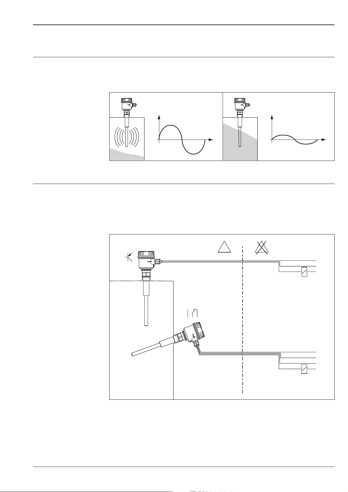
Measuring principle A piezoelectric drive excites the vibrating rod of Soliphant T FTM20, FTM21 to its resonance frequency.
If medium covers the vibrating rod, the rod's vibrating amplitude changes (the vibration is damped).
Soliphant's electronics compare the actual amplitude with a target value and indicates whether the vibrating
rod is vibrating freely or whether it is covered by medium.
L00-FTM2xxxx-15-06-xx-xx-001
A = amplitude
Measuring system Soliphant T is a compact electronic switch.
Thus, the entire measuring system only consists of:
• Soliphant T FTM20 or FTM21 with FEM22 or FEM24 electronic insert
• a supply point and
• the connected control systems, switching units, signalling systems (e.g. lamps, horns, PCS, PLC, etc.)
L00-FTM2xxxx-14-06-xx-xx-001
Endress+Hauser 3
Page 4

Cable specifications
Use a shielded cable in the event of strong electromagnetic radiation.
Temperature resistance The connecting cables must withstand an ambient temperature of +20 K.
Cable entries M20x1.5 (cable gland); NPT ½; G ½
Input
Measured variable Level (according to the mounting location and the overall length)
Soliphant T FTM20, FTM21
Measuring range (application)
Input signal Probes covered => small amplitude
Measuring frequency 700...800 Hz
The measuring range depends on the mounting location of Soliphant T and the length of the pipe extension
selected. The pipe extension is available in the following lengths: 500 mm, 1000 mm, 1500 mm (20 in, 40 in,
60 in).
Probe not covered => large amplitude
Output
Galvanic isolation FEM22:
Between sensor and power supply
FEM24:
Between sensor, power supply and load
Switch behaviour Binary
Power-on behaviour When switching on the power supply the output is set to "signal on alarm".
After a maximum of 3 s it switches to the correct output signal.
Fail-safe mode Minimum/maximum quiescent current safety can be switched at electronic insert
MAX = maximum safety:
When the vibrating rod is covered, the output switches in the direction of the signal on alarm
Used for overfill protection for example
MIN = minimum safety:
When the vibrating rod becomes exposed, the output switches in the direction of the signal on alarm
Used for empty running protection for example
Switching delay 0.5 s when the sensor is covered
1 s when the sensor is exposed
Ex specifications FEM22, FEM24:
– Explosion protection for explosive dust-air mixtures:
Dust-Ex, DIP
4 Endress+Hauser
Page 5
Soliphant T FTM20, FTM21
1 2 3
L+ L–
(+)
–
F
0.5 A
R
FEM22
U – 10 V…45 V(DC)
…
PE (Ground)
Relais,
PLC, ...
MAX
MIN
L+ +
1 3
L+ +
1 3
1 3
1 3
I
L
I
L
< 100 μA
< 100 μA
FEM22 electronic insert (DC PNP)
Power supply Voltage DC: 10…45 V
Ripple max. 5 V, 0…400 Hz
Current consumption max. 18 mA
Power consumption max. 0.81 W
Reverse polarity protection
Separation voltage: 2.2 kV
FEM22 overvoltage protection: overvoltage category II
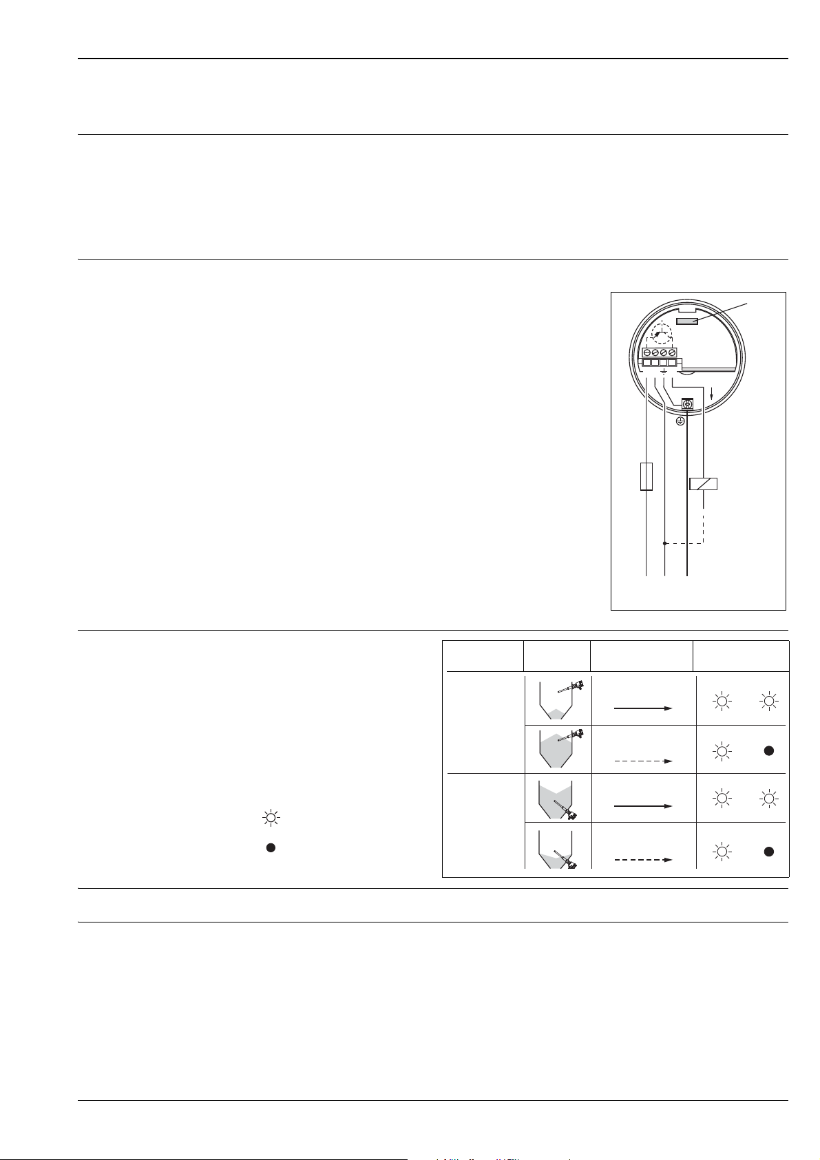
Electrical connection Three-wire direct current connection
Preferred in conjunction with programmable logic controllers (PLC),
DI modules as per EN 61131-2.
Positive signal at electronics switch output (PNP);
Output blocked at point level.
L00-FTM2xxxx-04-05-xx-xx-002
Output signal
IL
= Load current
Fail-safe
mode
Level Output signal LEDs
green yellow
(switched through)
< 100 μA
= Residual current
(blocked)
= Lit
L00-FTL2xxxx-07-05-
xx-xx-000
= Not lit
L00-FTM2xxxx-04-05-xx-xx-003
Signal on alarm Output signal on power failure or in the event of device failure: < 100 μA
Connectable load • Load switched via transistor and separate PNP connection
• Load current: max. 45 V (cyclical overload and short-circuit protection),
continuous max. 350 mA
• Residual current: < 100 μA (for blocked transistor)
• Capacitive load: max. 0.5 μF for 45 V, max. 1.0 μF for 24 V
• Residual voltage: < 3 V (for transistor switched through)
Endress+Hauser 5
Page 6
FEM24 electronic insert (AC/DC with relay output)
*
U~ 19…253 V U– 19… 55 V(AC) (DC)
…
…
L1
L+
a
NO
a
NO
u
C
u
C
r
NC
r
NC
**
NL–PE
(Ground)
F
0.5 A
12 678345
FEM24
**
MAX
MIN
354
354
687
687
354
354
687
687
Power supply Alternating voltage AC: 19…253 V, 50/60 Hz or DC voltage 19…55 V
Power consumption max. 1.3 W
Reverse polarity protection
Separation voltage: 2.2 kV
FEM24 overvoltage protection: overvoltage category II
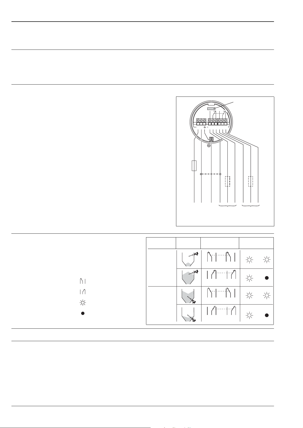
Electrical connection Universal current connection with relay output
Power supply:
Please note the different voltage ranges
for AC and DC.
Output:
When connecting a device with
high inductance, provide a spark arrester
to protect the relay contact.
A fine-wire fuse (depending on the
load connected) protects the relay
contact in the event of a short-circuit.
Both relay contacts switch simultaneously.
DPDT (double pole double throw)
Soliphant T FTM20, FTM21
* When jumpered, the
relay output works with NPN logic.
** See below "Connectable load"
Note!
Please note the different voltage ranges for direct and
alternating current.
Output signal
Fail-safe
Level Output signal LEDs
mode
= Relay energised
= Relay de-energised
= Lit
= Not lit
L00-FTL2xxxx-07-05-
xx-xx-001
Signal on alarm Output signal in event of power failure: relay de-energised
L00-FTM2xxxx-04-05-xx-xx-004
green yellow
L00-FTM2xxxx-04-05-xx-xx-005
Connectable load • Loads switched via 2 floating change-over contacts.
• I~ max. 6 A, U~ max. 253 V; P~ max. 1500 VA, cos = 1, P~ max. 750 VA, cos > 0.7;
• I- max. 6 A to 30 V, I- max. 0.2 A to 125 V.
6 Endress+Hauser
• The following applies when connecting a functional extra-low voltage circuit with double insulation as per
IEC 1010: Sum of voltages of relay output and power supply max. 300 V
Page 7
Soliphant T FTM20, FTM21
**
*
Operating conditions
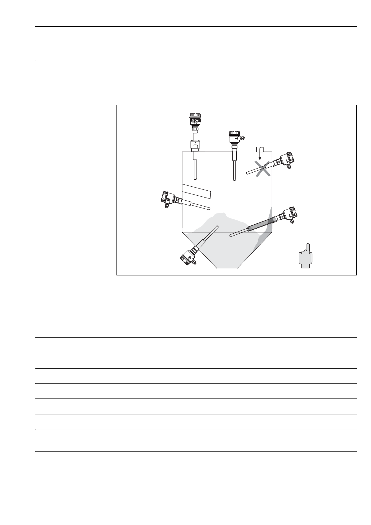
Installation instructions Mounting location
e.g. storage or buffer container
Orientation
Horizontal installation/vertical installation
* With protective cover (to be provided by customer)
** With protecting tube (to be provided by customer)
Environment
Ambient temperature range –40...70 °C (-40...158 °F)
Storage temperature –40...85 °C (-40...185 °F)
Climate class Climatic protection as per DIN IEC 68 Part 2-38, Fig. 2a
Degree of protection IP66/IP67, NEMA4X
Vibration resistance DIN 60068-2-27 / IEC 68-2-27: shock 30 g; vibration 0.01 g
Electrical safety IEC 61010, CSA 1010.1-92, FM3600
Electromagnetic compatibility Interference emission to EN 61326, Electrical Equipment Class B
Interference immunity to EN 61326, Annex A (Industrial)
L00-FTM20xxx-11-05-xx-xx-000
/Hz
Installation height as per IEC61010-1 Ed.3
Up to 2000 m (6600 ft) above sea level.
Endress+Hauser 7
Page 8
Soliphant T FTM20, FTM21
T
a
T
p
T
a
°C
T
p
°C
70
(158)
50
(122)
-40
(-40)
50
(122)90(194)
150
(302)
-40
(-40)
0
(32)
0
(32)
500 (112.4)
450 (101.16)
400 (89.92)
350 (78.68)
300 (67.44)
250 (56,2)
200 (44.96)
150 (33.72)
100 (22.48)
50 (11.24)
0
L
F
F
L
300
(11.8)
400
(15.7)
500
(19.7)
600
(23.6)
700
(27.6)
800
(31.5)
900
(35.4)
1000
(39.4)
1100
(43.3)
1200
(47.2)
1300
(51.2)
1400
(55.1)
1500
(59.1)
Process
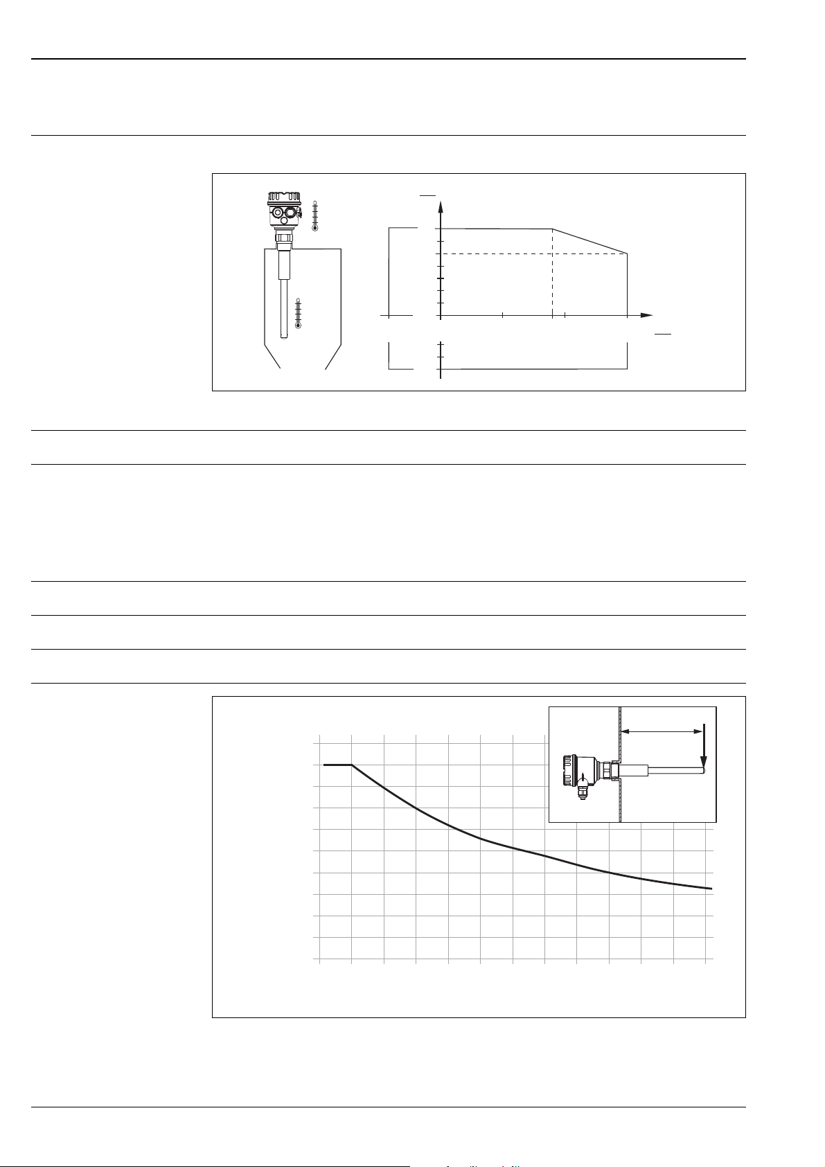
Environment Permitted ambient temperature Ta at housing depending on the medium temperature Tp in the container:
L00-FTM20xxx-05-06-xx-xx-001
Thermal shock resistance Maximum 120 K
Limiting medium pressure
–1...25 bar (-14.5...362.5 psi)
range
Maximum Working Pressure (MWP)
25 bar (362.5 psi)
Burst pressure
100 bar (1450 psi)
State of aggregation Solids
Grain size 25 mm (< 0,98 in)
Bulk density 200 g/l (26.7 oz/gal US), not fluidised
Lateral load
L00-FTM2xxxx-05-06-xx-xx-002
8 Endress+Hauser
F: Maximum permissible lateral load in Nm (lbf)
L: Length in mm (in)
Page 9
Soliphant T FTM20, FTM21
R 1½ / NPT 1½R 1 / NPT 1¼
50
41
≤76
(≤ 3)
100
(3.94)
Ø85
(Ø3.35)
Ø29
(Ø1.14)
Ø16
(Ø0.63 )
372
(14.6)
225
(8.86)
151
(5.94)
21,5
(0.85)
159.5 + L
L= x
151
ø80≤60
105
R 1½ / NPT 1½R 1 / NPT 1¼
≤76
(≤ 3)
21,5
(0.85)
41
50
( 3.15)ø
( 2.36)≤
Ø29
(Ø1.14)
Ø16
(Ø0.63)
()6.28 + L
()5.94
Mechanical construction
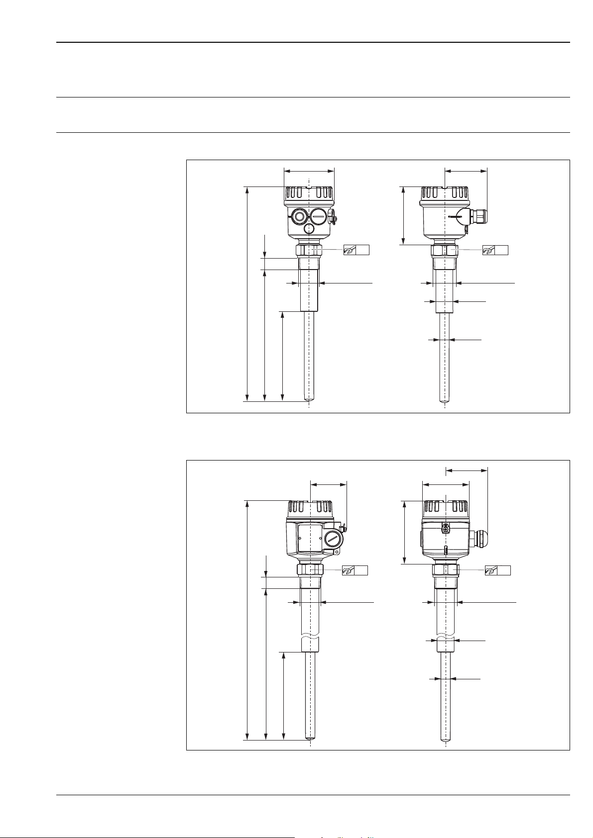
Note!
All dimensions in mm!
Design, dimensions Compact version
L00-FTM20xxx-06-05-xx-xx-001
Pipe extension
x = 500 mm, 1000 mm, 1500 mm (20 in, 40 in, 60 in)
Endress+Hauser 9
L00-FTM20xxx-06-05-xx-xx-000
Page 10
Weight FTM20/FTM21 with F16 housing, FEM24 and R 1 thread:
FEM22
L+L
-
MAX
MIN
3
1
U 10...45V DC
I max : 350mA
DC PNP
12 3
L1 N
FEM24
347568
4
35
MAX
MIN
19... 55V DC
19... 253V AC
U
~
–
12
34 5678
Compact = approx. 1.0 kg (2.21 lbs)
500 mm (20 in) = approx. 1.3 kg (2.87 lbs)
1000 mm (40 in) = approx. 2.0 kg (4.41 lbs)
1500 mm (60 in) = approx. 2.6 kg (5.73 lbs)
Material F16 housing:
PTB-FR, cover with sight glass made of PA12, EPDM cover seal
F18 housing:
Aluminium EN-AC-AlSi10Mg, plastic-coated
EPDM cover seal
Process connections:
• R1; R1½ (316L, DIN 2999)
• NPT 1¼ - 11½; NPT 1½ - 11½ (316L, ANSI B 1.20.1)
Sensor:
316L
Soliphant T FTM20, FTM21
Operability
Display elements Note!
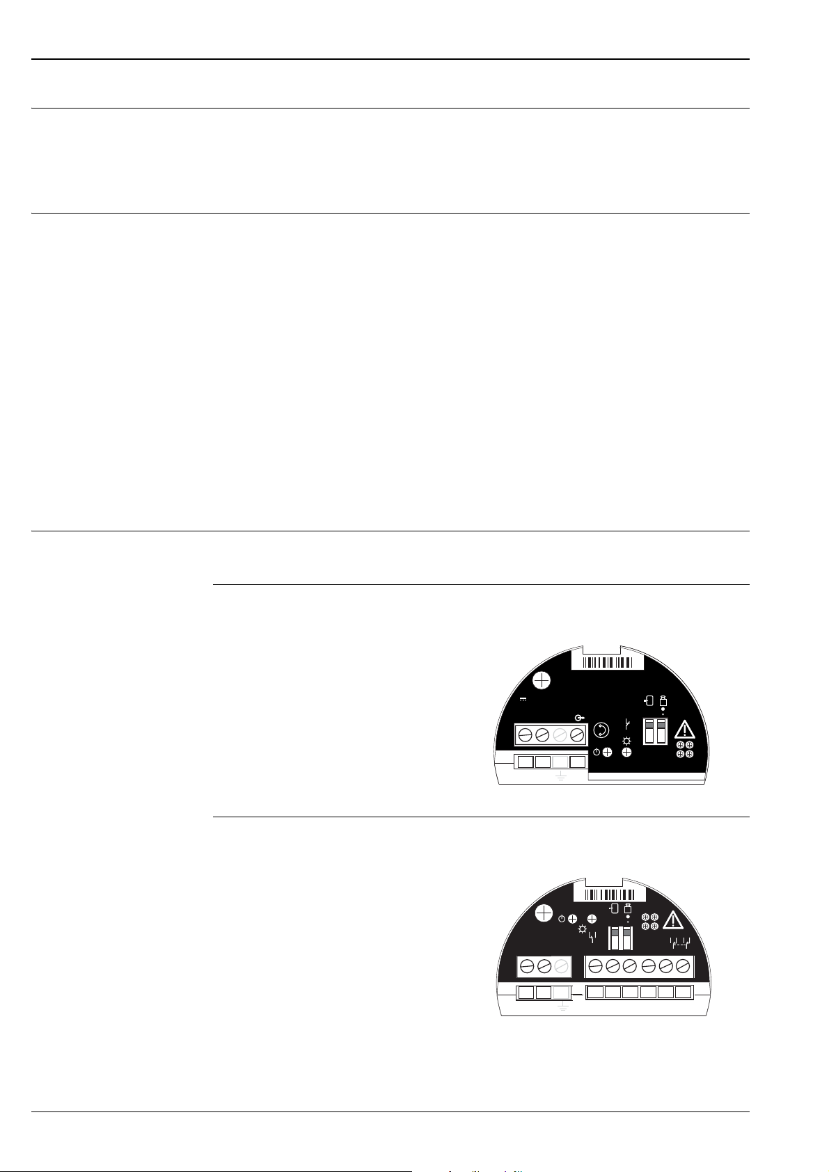
The switch settings in the following graphics are in the as-delivered state.
FEM22
One green LED: operation
One yellow LED: electronic switch closed
FEM24
One green LED: operation
One yellow LED: contact closed
(relay energised or fed with current)
L00-FEM22xxx-07-05-xx-x x-001
L00-FEM24xxx-07-05-xx-x x-002
10 Endress+Hauser
Page 11

Soliphant T FTM20, FTM21
MAX
MIN
HO
2
Operating elements of electronic inserts FEM22 and FEM24
(factory setting)
L00-FTM2xxxx-19-05-xx-xx-002
One switch for safety mode
MAX Overfill protection
MIN Dry running protection
One switch for bulk density/density setting
400 g/l (high bulk density)
200 g/l (low bulk density)
Sediment detection Detection of solids under water
The system does not detect coverage by liquids
similar to water.
L00-FTM2xxxx-19-05-xx-xx-001
Endress+Hauser 11
Page 12

Certificates and approvals
Soliphant T FTM20, FTM21
CE mark, declaration of conformity
Ex approval Your Endress+Hauser sales centre can provide you with information on the Ex versions which can currently
Type of protection See "Ordering information" as of Page 13 and "Supplementary documentation" on Page 15.
Other standards and guidelines
Pressure Equipment Directive 2014/68/EU (PED)
The measuring system meets the legal requirements of the applicable EC Directives. These are listed in
the corresponding EC Declaration of Conformity along with the standards applied.
Endress+Hauser confirms successful testing of the device by affixing to it the CE mark.
be delivered.
All explosion protection data are given in a separate documentation (see "Supplementary Documentation")
which is available upon request.
Copies of certificates available upon request.
Other standards and guidelines that were taken into consideration in designing and developing Soliphant T
FTM20, FTM21:
• Low Voltage Directive (73/23/EEC)
• DIN EN 61010 Part 1, 2001
Protection Measures for Electrical Equipment for Measurement, Control, Regulation and Laboratory
Procedures
Part 1: General requirements
• EN 61326
Electrical Equipment for Measurement, Control and Laboratory Use
EMC requirements
Pressure instruments with permitted pressure ≤ 200 bar (2 900 psi)
Pressure instruments with permitted pressure ≤ 200 bar (2 900 psi) Pressure instruments with a
flange and threaded boss that do not have a pressure-bearing housing do not fall within the scope of
the Pressure Equipment Directive, irrespective of the maximum permitted pressure.
Reason:
According to Article 2, point 5 of EU Directive 2014/68/EU, pressure accessories are defined as
"devices with an operational function and having pressure-bearing housings".
If a pressure instrument does not have a pressure-bearing housing (no identifiable pressure chamber
of its own), there is no pressure accessory present within the meaning of the Directive.
Note:
A separate analysis must be performed for pressure instruments that are part of safety equipment
designed to protect a pipe or vessel from exceeding allowable limits (safety accessory in accordance
with Pressure Equipment Directive 2014/68/EU, Article 2, point 4).
RCM-tick mark The product or measuring system supplied complies with the regulations of the Australian
Communications and Media Authority (ACMA) for network integrity, performance characteristics and
health and safety requirements. The specifications for electromagnetic compatibility, in particular, are
observed. The products bear the RCM-tick mark on their nameplate.
EAC conformity The measuring system meets the legal requirements of the applicable EAC Directives.
These are listed in the corresponding EAC Declaration of Conformity along with the standards applied.
A0029561
Endress+Hauser confirms successful testing of the device by affixing to it the EAC mark.
RoHS The measuring system complies with the substance restrictions of the EU Directive on the restriction
of the use of certain hazardous substances 2011/65/EU (RoHS 2).
12 Endress+Hauser
Page 13
Soliphant T FTM20, FTM21
Ordering information
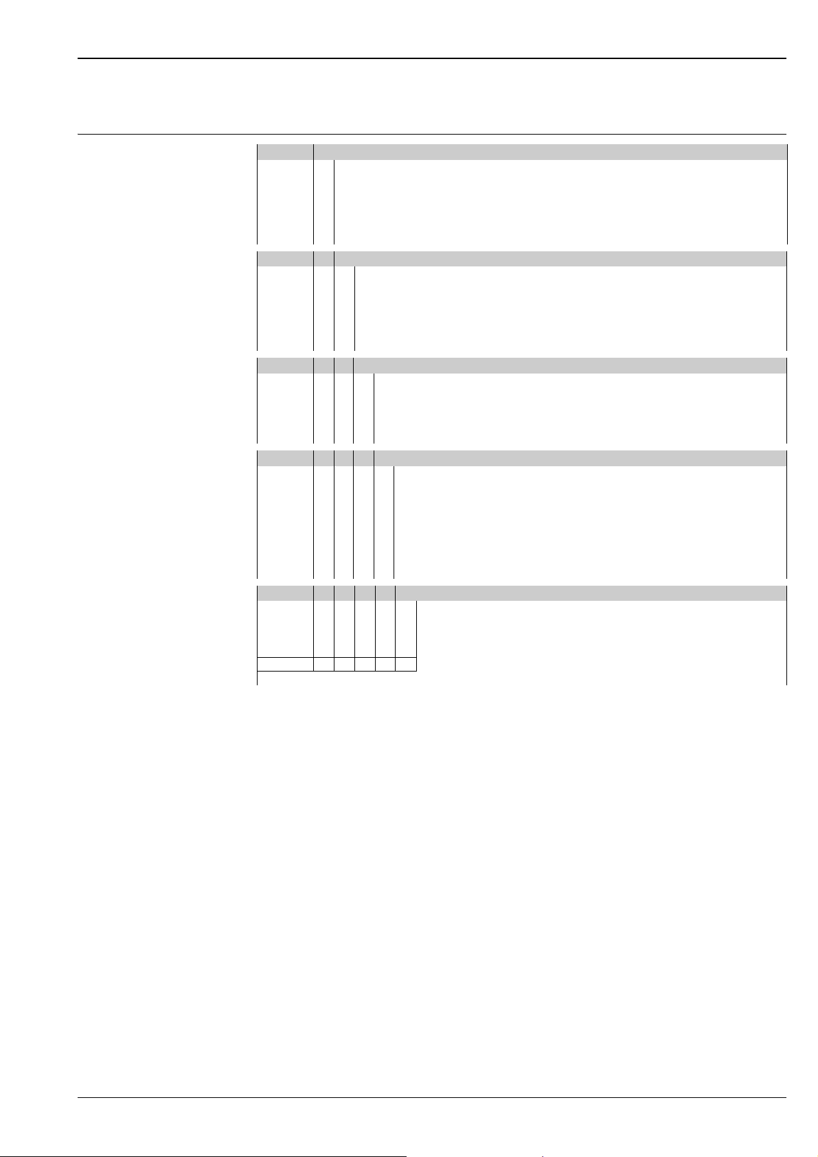
Soliphant T FTM20
10 Approval
A Non-hazardous area
C CSA General Purpose, CSA C US
D CSA DIP+FM DIP
YSpecial version
4 ATEX II 1/3 D
20 Process connection
A Thread, DIN2999 R1, 316L
G Thread, DIN2999 R1½, 316L
M Thread, ANSI NPT1¼, 316L
N Thread, ANSI NPT1½, 316L
Y Special version
30 Electronics; output
2 FEM22: 3-wire PNP, 10...45 V DC
4 FEM24: Relay DPDT, 19...253 V AC / 55 V DC
8 FEM20B ASI Bus
9 Special version
40 Housing; cable entry
2 F16 Polyester IP66/IP67, NEMA4X M20 gland
3 F16 Polyester IP66/IP67, NEMA4X Thread, NPT½
4 F16 Polyester IP66/IP67, NEMA4X Thread, G½
5 F18 Aluminium IP66/IP67, NEMA4X M20 gland
6 F18 Aluminium IP66/IP67, NEMA4X Thread, NPT¾
7 F18 Aluminium IP66/IP67, NEMA4X Thread, G½
9 Special version
50 Additional fittings
A Basic version
Y Special version
FTM20 Complete product designation
Endress+Hauser 13
Page 14
Soliphant T FTM20, FTM21
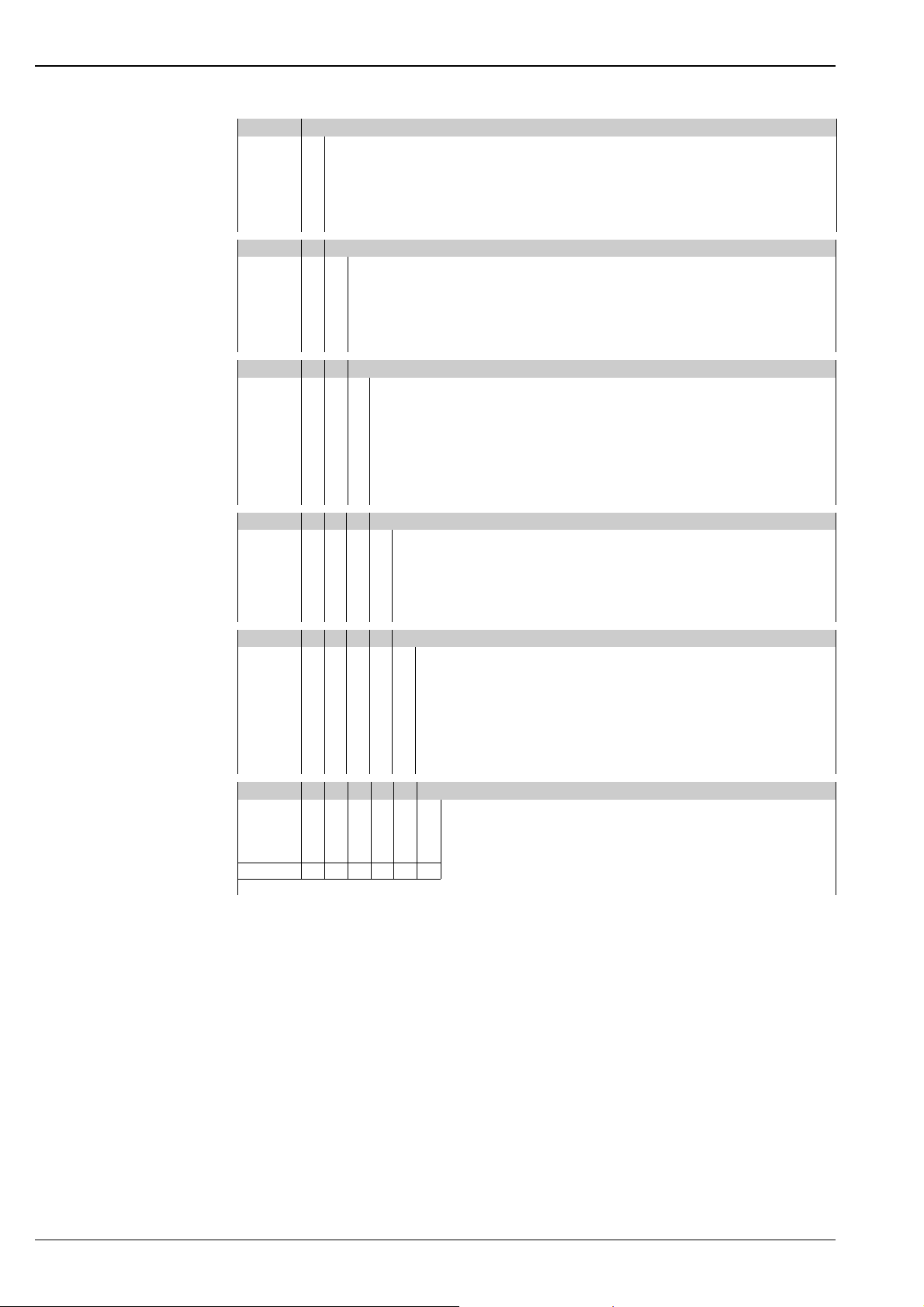
Soliphant T FTM21
10 Approval
A Non-hazardous area
C CSA General Purpose, CSA C US
DCSA DIP+FM DIP
Y Special version
4 ATEX II 1/3 D
20 Process connection
A Thread, DIN2999 R1, 316L
G Thread, DIN2999 R1½, 316L
M Thread, ANSI NPT1¼, 316L
N Thread, ANSI NPT1½, 316L
Y Special version
25 Sensor length
2 500 mm
3 1000 mm
4 1500 mm
6 20 inch
7 40 inch
8 60 inch
9 Special version
30 Electronics; output
2 FEM22: 3-wire PNP, 10...45 V DC
4 FEM24: Relay DPDT, 19...253 V AC / 55 V DC
8FEM20BASI Bus
9 Special version
40 Housing; cable entry
2 F16 Polyester IP66/IP67, NEMA4X M20 gland
3 F16 Polyester IP66/IP67, NEMA4X Thread, NPT½
4 F16 Polyester IP66/IP67, NEMA4X Thread, G½
5 F18 Aluminium IP66/IP67, NEMA4X M20 gland
6 F18 Aluminium IP66/IP67, NEMA4X Thread, NPT¾
7 F18 Aluminium IP66/IP67, NEMA4X Thread, G½
9 Special version
50 Additional fittings
A Basic version
Y Special version
FTM21 Complete product designation
14 Endress+Hauser
Page 15
Soliphant T FTM20, FTM21
MWP = 25 bar
T = max. 150 °C
(360 psi)
(max. 300 °F)
a
22
M 6x25
1½ - 11½ NPT
5
60
ø70
(ø2.76)
~70
(~2.76)
(0.87)
25
(0.98)
R 1½
MWP = 0 bar
T = max. 150 °C
(0 psi)
(max. 300 °F)
a
22
G 1¼
1½ - 11½ NPT
23
M6
(3x)
ø28.17
x 3.53
50
50
(0.91)
(0.87)
57.5
10
24.5
(2.26)
(0.96)
(0.39)
R 1½
Accessories
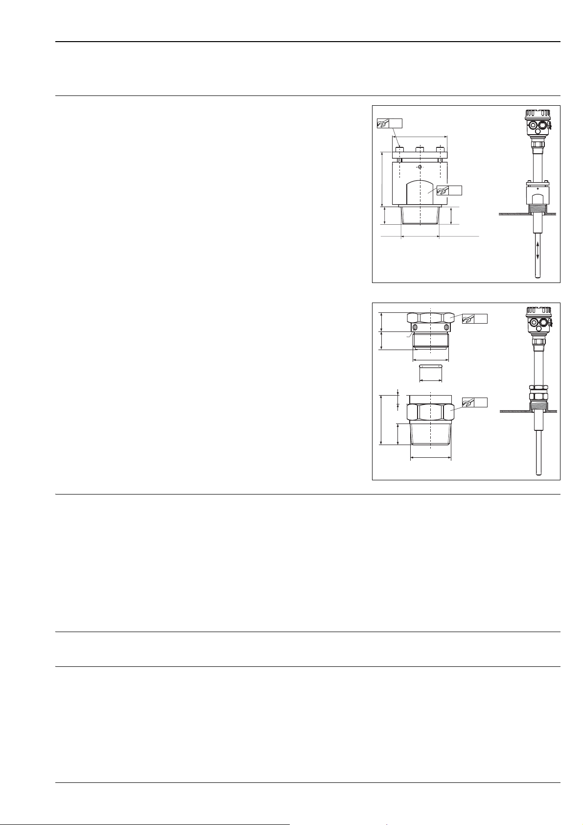
Sliding sleeve
For pressurised container
• R 1½
DIN 2999
Material number: 52023312
• NPT 1½ - 11½
ANSI B 1.20.1
Material number: 52025090
Note!
Suitable for multiple switch-point configurations!
L00-FTM2xxxx-03-05-xx-xx-001
For unpressurised container, IP65
• R 1½
DIN 2999
Material number: 52023313
• NPT 1½ - 11½
ANSI B 1.20.1
Material number: 52024578
Note!
Only suitable for one-time switch-point
configuration!
Spare parts • FEM22 electronic insert: 52025688
• FEM24 electronic insert: 52025691
• Cover for polyester housing (F16), transparent plastic with seal: 52025790
• Cover for aluminium housing (F18), aluminium with seal: 52005910
• Cover for aluminium housing (F18), aluminium with glass insert and seal (not for EEx d): 52027693
Supplementary documentation
Operating Instructions • Soliphant T FTM20, FTM21
KA00227F
Certificates • ATEX II 1/3 D T +12 K
XA00300F
L00-FTM2xxxx-03-05-xx-xx-002
Endress+Hauser 15
Page 16

www.addresses.endress.com
71346118
 Loading...