

Page 1
TI00398F/00/EN/16.16
71308102
Products Solutions Services
Technical Information
Prosonic S FMU95
Ultrasonic measurement
Time-of-Flight
Transmitter for up to 10 sensors
FDU90/91/91F/92/93/95
Field of application
Continuous, non-contact level measurement of fluids, pastes, sludge and powdery to
coarse bulk materials with up to 5 or 10 ultrasonic sensors
• Measuring range up to 45 m (148 ft) (depending on sensor and material measured)
• Calculation of average values or sums
• Transmitter available with field housing or top hat rail housing for control cabinet
instrumentation
Benefits
• Simple, menu-guided operation with 6-line plain text display, 15 languages
selectable
• Envelope curves on the display for quick and simple diagnosis
• Easy operation, diagnosis and measuring point documentation with the supplied
"FieldCare" operating program
• Time-of-Flight correction via integrated or external temperature sensors
• Linearization (up to 32 points, freely configurable)
• System integration via PROFIBUS DP with up to 20 measured values
Page 2

Table of Contents
Prosonic S FMU95
Function and system design . . . . . . . . . . . . . . . . . . . . . .3
Measuring principle . . . . . . . . . . . . . . . . . . . . . . . . . . . . . . . . . . . 3
Blocking distance . . . . . . . . . . . . . . . . . . . . . . . . . . . . . . . . . . . . . . 3
Time-of-flight correction . . . . . . . . . . . . . . . . . . . . . . . . . . . . . . . 3
Interference echo suppression . . . . . . . . . . . . . . . . . . . . . . . . . . . 3
Linearization . . . . . . . . . . . . . . . . . . . . . . . . . . . . . . . . . . . . . . . . . . 3
Datalog functions . . . . . . . . . . . . . . . . . . . . . . . . . . . . . . . . . . . . . . 4
Application examples . . . . . . . . . . . . . . . . . . . . . . . . . . . . . . . . . . 4
System integration PROFIBUS DP . . . . . . . . . . . . . . . . . . . . . . . 5
Input . . . . . . . . . . . . . . . . . . . . . . . . . . . . . . . . . . . . . . . . . .5
Sensor inputs . . . . . . . . . . . . . . . . . . . . . . . . . . . . . . . . . . . . . . . . . 5
Output . . . . . . . . . . . . . . . . . . . . . . . . . . . . . . . . . . . . . . . . .6
PROFIBUS DP interface . . . . . . . . . . . . . . . . . . . . . . . . . . . . . . . . . 6
Power supply . . . . . . . . . . . . . . . . . . . . . . . . . . . . . . . . . . .6
Supply voltage / Power consumption /Current consumption . 6
Galvanic isolation . . . . . . . . . . . . . . . . . . . . . . . . . . . . . . . . . . . . . 6
Fuse . . . . . . . . . . . . . . . . . . . . . . . . . . . . . . . . . . . . . . . . . . . . . . . . . 6
Electrical connection. . . . . . . . . . . . . . . . . . . . . . . . . . . . .7
Terminal compartment of the field housing . . . . . . . . . . . . . . . 7
Cable entries of the field housing . . . . . . . . . . . . . . . . . . . . . . . . 7
Terminal compartment of the DIN-rail housing . . . . . . . . . . . . 7
Terminals . . . . . . . . . . . . . . . . . . . . . . . . . . . . . . . . . . . . . . . . . . . . 9
Terminal assignment . . . . . . . . . . . . . . . . . . . . . . . . . . . . . . . . . . 9
Connection of the sensors FDU9x . . . . . . . . . . . . . . . . . . . . . . . 11
Synchronization line . . . . . . . . . . . . . . . . . . . . . . . . . . . . . . . . . . 12
Connection of the separate display and operating module . . 12
Operating menu . . . . . . . . . . . . . . . . . . . . . . . . . . . . . . . . . . . . . . 16
Basic setup . . . . . . . . . . . . . . . . . . . . . . . . . . . . . . . . . . . . . . . . . . 16
Locking of the instrument. . . . . . . . . . . . . . . . . . . . . . . . . . . . . 16
Certificates and Approvals. . . . . . . . . . . . . . . . . . . . . . 17
CE mark . . . . . . . . . . . . . . . . . . . . . . . . . . . . . . . . . . . . . . . . . . . . 17
Ex approval . . . . . . . . . . . . . . . . . . . . . . . . . . . . . . . . . . . . . . . . . . 17
External standards and guidelines . . . . . . . . . . . . . . . . . . . . . . 17
Ordering information . . . . . . . . . . . . . . . . . . . . . . . . . . 18
Product structure . . . . . . . . . . . . . . . . . . . . . . . . . . . . . . . . . . . . . 18
Scope of delivery . . . . . . . . . . . . . . . . . . . . . . . . . . . . . . . . . . . . . 18
Accessories . . . . . . . . . . . . . . . . . . . . . . . . . . . . . . . . . . . 19
Commubox FXA291 . . . . . . . . . . . . . . . . . . . . . . . . . . . . . . . . . . 19
Protection cover for the field housing . . . . . . . . . . . . . . . . . . . . 19
Mounting plate for the field housing . . . . . . . . . . . . . . . . . . . . 19
Mounting bracket . . . . . . . . . . . . . . . . . . . . . . . . . . . . . . . . . . . . 20
Adaption plate for remote display . . . . . . . . . . . . . . . . . . . . . . . 20
Overvoltage protection HAW562 . . . . . . . . . . . . . . . . . . . . . . . 21
Documentation . . . . . . . . . . . . . . . . . . . . . . . . . . . . . . . 23
Technical Information . . . . . . . . . . . . . . . . . . . . . . . . . . . . . . . . . 23
Operating Instructions . . . . . . . . . . . . . . . . . . . . . . . . . . . . . . . . 23
Safety Instructions . . . . . . . . . . . . . . . . . . . . . . . . . . . . . . . . . . . . 23
Performance characteristics . . . . . . . . . . . . . . . . . . . . 13
Reference operating conditions . . . . . . . . . . . . . . . . . . . . . . . . . 13
Maximum measuring error . . . . . . . . . . . . . . . . . . . . . . . . . . . . 13
Typical measuring error
Measured value resolution . . . . . . . . . . . . . . . . . . . . . . . . . . . . . 13
Measuring frequency . . . . . . . . . . . . . . . . . . . . . . . . . . . . . . . . . 13
5)
. . . . . . . . . . . . . . . . . . . . . . . . . . . . . . 13
Operating conditions: Environment. . . . . . . . . . . . . . 13
Ambient temperature . . . . . . . . . . . . . . . . . . . . . . . . . . . . . . . . . 13
Storage temperature . . . . . . . . . . . . . . . . . . . . . . . . . . . . . . . . . . 13
Climate class . . . . . . . . . . . . . . . . . . . . . . . . . . . . . . . . . . . . . . . . . 13
Vibration resistance . . . . . . . . . . . . . . . . . . . . . . . . . . . . . . . . . . 13
Ingress protection . . . . . . . . . . . . . . . . . . . . . . . . . . . . . . . . . . . . 13
Electromagnetic compatibility (EMC) . . . . . . . . . . . . . . . . . . . . 13
Mechanical construction . . . . . . . . . . . . . . . . . . . . . . . 14
Housing versions . . . . . . . . . . . . . . . . . . . . . . . . . . . . . . . . . . . . . 14
Dimensions of the field housing . . . . . . . . . . . . . . . . . . . . . . . . 14
Dimensions of the DIN-rail housing . . . . . . . . . . . . . . . . . . . . . 14
Dimensions of the separate display and operating module . . 15
Weight . . . . . . . . . . . . . . . . . . . . . . . . . . . . . . . . . . . . . . . . . . . . . 15
Materials . . . . . . . . . . . . . . . . . . . . . . . . . . . . . . . . . . . . . . . . . . . . 15
Human interface . . . . . . . . . . . . . . . . . . . . . . . . . . . . . . 16
Display and operating module . . . . . . . . . . . . . . . . . . . . . . . . . . 16
2 Endress+Hauser
Page 3
Prosonic S FMU95
100%
0%
D
L
F
E
1
BD
V
2
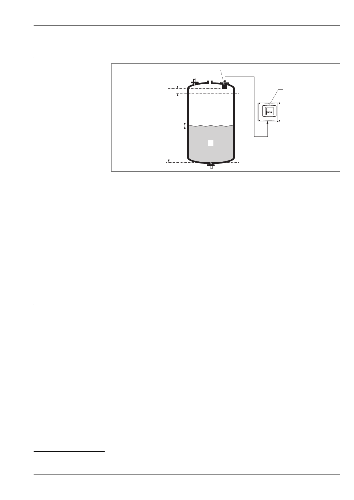
Measuring principle
Function and system design
L00-FMU95xxx-15-00-08-xx-900
BD: Blocking distance, D: Distance from sensor membrane to fluid surface, E: Empty distance F: Span (full distance),
L: Level, V: Volume (or mass)
The sensor transmits ultrasonic pulses in the direction of the product surface. There, they are reflected
back and received by the sensor. The transmitter Prosonic S measures the time t between pulse
transmission and reception. From t (and the velocity of sound c) it calculates the distance D from the
sensor membrane to the product surface:
D = c · t/2
From D results the desired measuring value:
• Level L
•Volume V
Blocking distance The span F may not extend into the blocking distance BD. Level echoes within the blocking distance
range can not be evaluated due to the transient characteristics of the sensor.
The blocking distances of the individual sensors are given in the following documents:
• TI00396F for the sensors FDU90/91/91F/92/93/95
1)
Time-of-flight correction In order to compensate for temperature dependent time-of-flight changes, a temperature sensor
(NTC) is integrated in the ultrasonic sensors.
Interference echo suppression
The interference echo suppression feature of the Prosonic S ensures that interference echoes (e.g. from
edges, welded joints and installations) are not interpreted as a level echo.
Linearization Pre-programmed linearization curves for specific types of vessels
• Horizontal, cylindrical tank
•Spherical tank
• Tank with pyramidal bottom
• Tank with conical bottom
• Tank with flat, inclined bottom
The pre-programmed linearization curves are calculated on-line.
Linearization table
consisting of up to 32 linearization points; to be entered manually or half-automatically.
1) The sensors FDU80/80F/81/81F/82/83/84/85/86/96 are not available anymore.
Use the serial number of your device to access the documentation for your device via www.endress.com.
Endress+Hauser 3
Page 4
Datalog functions Basic version
Prosonic S
L1
min
FDU9x
max
min
FDU9x
max
min
FDU9x
max
min
FDU9x
max
min
FDU9x
max
min
FDU9x
max
min
FDU9x
max
min
FDU9x
max
FDU9xFDU9x
L2
L1 + L2 + ... LN
L3
LN
Prosonic S
L1 + ... + LN
N
L1
L1
• Peak hold indicator of the min./max. levels and the min./max. temperatures at the sensors
• Recording of the last 10 alarms
• Indication of the operating status
• Indication of the operating hours
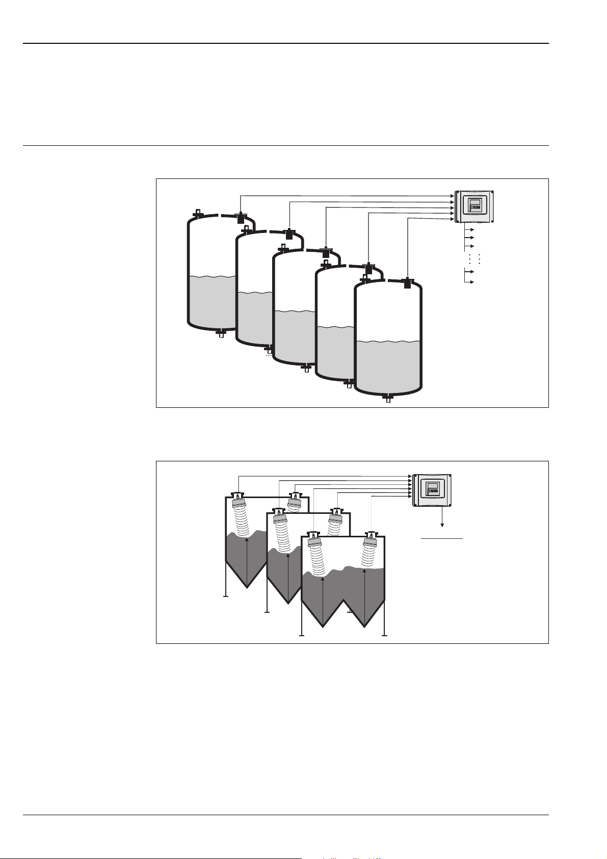
Application examples Multi-channel level measurement with sum calculation
Prosonic S FMU95
Multi-channel level measurement with average calculation
L00-FMU95xxx-15-00-00-xx-010
L00-FMU95xxx-15-00-00-xx-003
4 Endress+Hauser
Page 5
Prosonic S FMU95
PROFIBUS DP
SPS /
PLC/
API
Ethernet
PDM
...
Prosonic S
PROFIboard
PROFIcard
PROFIusb
Commubox
FXA 291
FieldCare
T
T
FieldCare
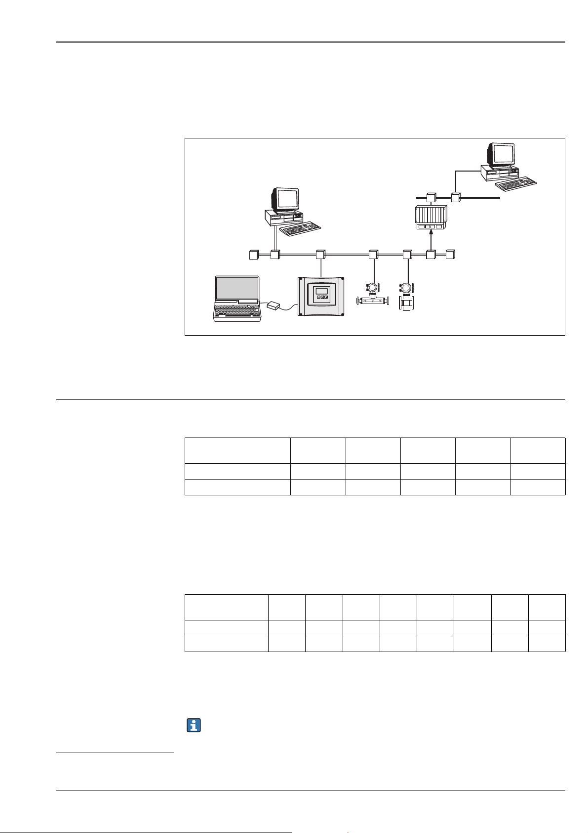
System integration PROFIBUS DP
Operating options
• Via the display and operating module at the Prosonic S
• Via the service interface with the Commubox FXA291 and the operating program FieldCare
• Via PROFIBUS DP with PROFIboard, PROFIcard or PROFIusb and the operating program FieldCare
L00-FMU90xxx-14-00-00-xx-021
Input
Sensor inputs Depending on the instrument version, 1 or 2 of the sensors FDU90, FDU91, FDU91F, FDU92, FDU93,
FDU95 can be connected. The Prosonic S identifies these sensors automatically.
FDU91
FDU91F
Max. range
Max. range
Sensor FDU90
1)
in liquids
1
in solids 1.2 (3.9) 5 (16) 10 (33) 15 (49) 45 (148)
3 (9.8) 10 (33) 20 (66) 25 (82) -
m (ft)
1) This table gives the maximum range. The range depends on the measuring conditions. For an estimation
see Technical Information TI00396F, Chapter "Input".
In order to support existing installations, the following sensors can be connected as well.
sensor must be entered manually (except FDU96).
Max. range
Max. range
m (ft)
Sensor
1)
in liquids
1
in solids 2 (6.6) 5 (16) 10 (33) 15 (49) 25 (82) 45 (148) 70 (230) 70 (230)
FDU80
FDU80F
5 (16) 10 (33) 20 (66) 25 (82) - - - -
FDU81
FDU81F
FDU82 FDU83 FDU84 FDU85 FDU86 FDU96
FDU92 FDU93 FDU95
2)
The type of
1) This table gives the maximum range. The range depends on the measuring conditions. For an estimation
see Technical Information TI00189F, Chapter "Planning Recommendations".
The sensors FDU83, FDU84, FDU85 and FDU86 with an ATEX, FM or CSA certificate are not
certified for connection to the FMU95 transmitter.
2) The sensors FDU80/80F/81/81F/82/83/84/85/86/96 are not available anymore.
Use the serial number of your device to access the documentation for your device via www.endress.com.
Endress+Hauser 5
Page 6
Output
Prosonic S FMU95
PROFIBUS DP interface
Profile 3.0
Transmittable values • Main value (level 1 to level 10
•Distances
•Temperatures
• Averages/sums
Function blocks • 20 Analog Input Blocks (AI)
Supported baud rates • 9.6 kbaud
•19.2kbaud
• 45,45 kbaud
• 93.75 kbaud
• 187.5 kbaud
•500kbaud
•1.5Mbaud
•3Mbaud
•6Mbaud
•12Mbaud
Service Access Points
(SAPs)
ID number 154E (hex) = 5454 (dec)
GSD file EH3x154E.gsd
Addressing Via dip switches at the instrument or via software (e.g. FieldCare)
Termination Can be activated/deactivated in the instrument.
Locking The device can be locked by hardware or software.
2
Default address: 126 per software
Power supply
Supply voltage / Power consumption / Current consumption
Galvanic isolation The following terminals are galvanically isolated from each other:
Fuse •2AT/DC
Instrument version Supply voltage Power consumption Current consumption
AC voltage
(FMU95 - ****A****)
DC voltage
(FMU95 - ****B****)
90 to 253 V
10,5 to 32 V
(50/60 Hz) max. 23 VA max. 100 mA at 230 V
AC
DC
max. 14 W (typically 8 W) max. 580 mA at 24 V
• Auxiliary energy
•Sensor inputs
• Bus connection (PROFIBUS DP)
• 400 mA T /AC
Accessible in the terminal compartment
AC
DC
6 Endress+Hauser
Page 7
Prosonic S FMU95
1.
2.
3.
1.
2.
1.
2.
Electrical connection
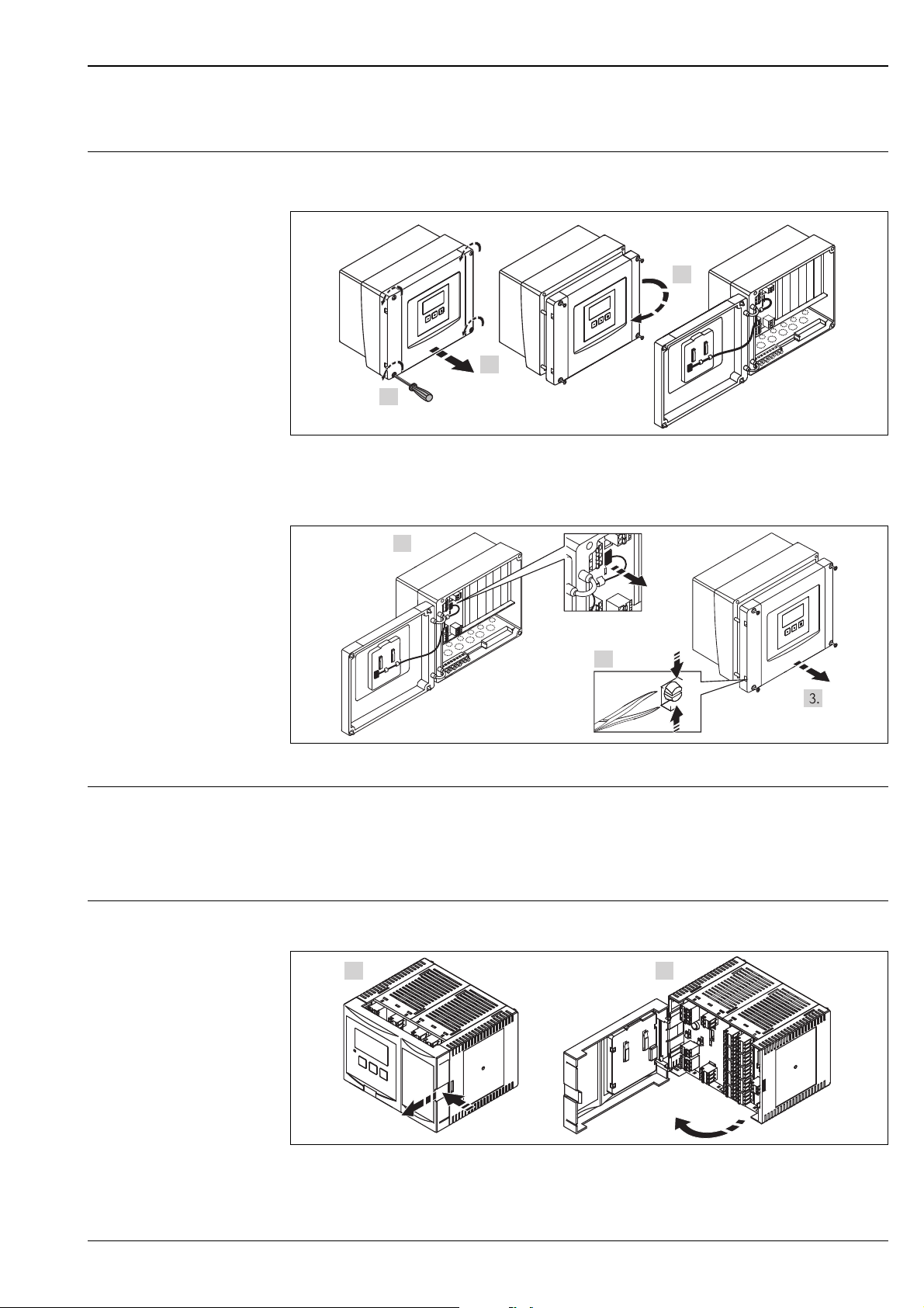
Terminal compartment of the field housing
The field housing has a separate terminal compartment. It can be opened after loosening the 4 screws
of the lid.
L00-FMU90xxx-04-00-00-xx-002
For easier wiring, the lid can be completely removed by unplugging the display plug and loosening the
hinges:
L00-FMU90KAx-04-00-00-xx-009
Cable entries of the field housing
On the bottom of the housing the following openings for cable entries are prestamped:
• M20x1.5 (10 openings)
• M16x1.5 (5 openings)
• M25x1.5 (1 opening)
A suitable cutting device must be used for cutting out the openings.
Terminal compartment of the
Single instrument
DIN-rail housing
L00-FMU95xxx-04-00-00-xx-005
The catch can be unlocked by slightly pressing onto the clip. Then, the cover of the terminal
compartment can be opened.
Endress+Hauser 7
Page 8
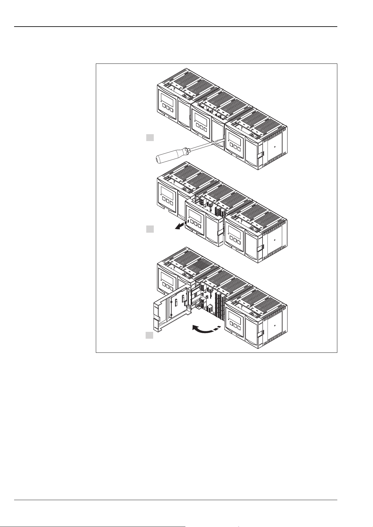
Several instruments mounted side by side
1.
2.
3.
Prosonic S FMU95
L00-FMU95KAx-04-00-00-xx-005
Open the catch of the cover (e.g. by a screwdriver).
Pull the cover out by approx. 20 mm (0.79 in).
The cover can now be opened.
• The cables can be inserted into the housing from above or from below.
• If the instruments are mounted next to each other and if the sensor cables run in parallel, the
synchronization terminals (39 and 40) must be interconnected (see sections → ä 9 "Terminal
assignment" and → ä 12 "Synchronization line").
8 Endress+Hauser
Page 9

Prosonic S FMU95
Address
Te rm.
DP
off
on
off
on
SW
HW
1
2
3
4
5
6
7
8
1
2
3
4
A(N)
66
B(P)
65
Display
POWER
Sync
Fuse
40
39
Service
32
1
11
10
9
1
FDU-Sensor
YE BK R
D
14
13
12
2
YE BK R
D
17
16
15
3
YE BK R
D
20
19
18
4
YE BK R
D
23
22
21
5
YE BK R
D
26
25
24
6
YE BK R
D
29
28
27
7
YE BK R
D
32
31
30
8
YE BK R
D
35
34
33
9
YE BK R
D
38
37
36
10
YE BK R
D
FDU-Sensor
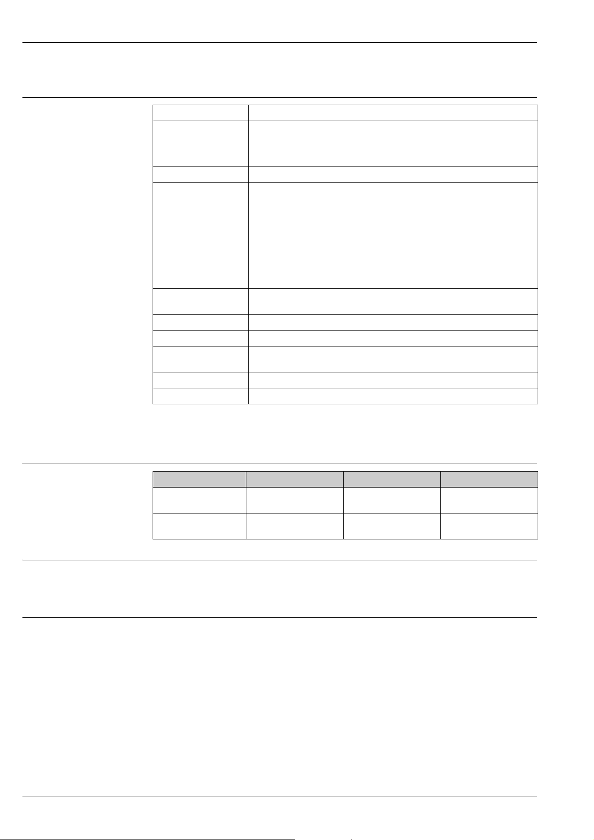
Terminals Pluggable spring-force terminals for connection of the cables are supplied in the terminal
compartment. Rigid conductors or flexible conductors with cable sleeve can directly be inserted and are
contacted automatically.
Feature Value
Conductor cross section 0,2 mm
Cable and sleeve cross section 0,25 mm
2
to 2,5 mm2 (26 to 14 AWG)
2
to 2,5 mm2 (24 to 14 AWG)
Min. stripping length 10 mm (0.39 in)
Terminal assignment
L00-FMU90xxx-04-00-00-xx-001
Terminals of the Prosonic S FMU95; the terminals depicted in grey are not present in every instrument version.
Terminals Meaning Remarks
Auxiliary energy
1
2
• L (for AC version)
•L+ (for DC version)
•N (for AC version)
•L- (for DC version)
Depending on instrument version:
• 90 to 253 V
• 10,5 to 32 V
AC
DC
3 Potential equalization
Depending on instrument version:
Fuse
• 400 mA T (for AC)
•2AT (for DC)
Bus communication
65 PROFIBUS A (RxT/TxD - N)
66 PROFIBUS B (RxT/TxD - P)
Endress+Hauser 9
Synchronization
39, 40 Synchronization See section "Synchronization line"
Level inputs
09,10,11 Sensor 1 (FDU8x/9x)
12, 13, 14 Sensor 2 (FDU8x/9x)
15, 16, 17 Sensor 3 (FDU8x/9x)
18, 19, 20 Sensor 4 (FDU8x/9x)
21, 22, 23 Sensor 5 (FDU8x/9x)
YE: yellow strand
BK: black strand
RD: red strand
Page 10

Prosonic S FMU95
CAUTION
!
Terminals Meaning Remarks
24, 25, 26 Sensor 6 (FDU8x/9x)
27, 28, 29 Sensor 7 (FDU8x/9x)
30, 31, 32 Sensor 8 (FDU8x/9x)
33, 34, 35 Sensor 9 (FDU8x/9x)
36, 37, 38 Sensor 10 (FDU8x/9x)
Only available for the version with 10 sensor inputs
YE: yellow strand
BK: black strand
RD: red strand
Limitation of electrical safety.
‣ When using the public supply mains, an easily accessible power switch must be installed in the
proximity of the device. The power switch must be marked as a disconnector for the device (IEC/
EN 61010).
In order to avoid interference, do not route the sensor cables parallel to high-voltage or
electric power lines and not close to frequency converters.
Additional elements on the terminal areas
Designation Meaning/Remarks
Fuse Fuse: 2 A T /DC or 400 mA T/AC
Display Connection of the display or the remote display and operating module
Service Service interface for connection of a PC/Notebook via Commubox FXA291
Locking switch
Term. Bus termination
Address Bus address
10 Endress+Hauser
Page 11

Prosonic S FMU95
YE
BK
RD
FDU90/91/92
BK
YE
RD
(1)
FDU91F/93/95
GNYE
(2)
(3)
FMU95
(1)
(2)
(3)
A
FDU91F/93/95
(1)
B
max.
30 m
FDU90/91/92
FDU91F/93/95
max.
300 m
YE
BK
RD
YE
BK
RD
FMU95
FMU95
BK
YE
RD
BK
YE
RD
GNYE
max.
30 m
max.
300 m
Connection of the sensors FDU9x
(A): grounding at the terminal box,
(B): grounding at the transmitter FMU95,
(1): screen of the sensor cable,
(2): terminal box,
(3): screen of the extension cable
Colours of the strands: YE = yellow; BK = black; RD = red; BU = blue; BN = brown; GNYE = green-yellow
For details on the sensor connection refer to Technical Information TI00396F3).
L00-FMU95xxx-04-00-00-xx-004
3) The sensors FDU80/80F/81/81F/82/83/84/85/86/96 are not available anymore.
Use the serial number of your device to access the documentation for your device via www.endress.com.
Endress+Hauser 11
Page 12

Prosonic S FMU95
Prosonic S
FMU90/95
39 40
1
2 3
20
……
FMU90 FMU90 FMU90
Prosonic S
FMU90/95
39 40
Prosonic S
FMU90/95
39 40
Prosonic S
FMU90/95
39 40
Prosonic
FMU860/861/862
63 64
1
2
10
……
FMU90
VH
Display
POWER
HART
0/4…20mA
Sync
Fuse
I
1
FDU-
Sensor
RD
11
BK
10
YE
9
40
39
5
4
6
7
8
Service
Relay
3
2
1
1
Synchronization line
• If wiring several Prosonic S (FMU90/FMU95)
which are mounted in a common cabinet and if
the sensor cables run in parallel, the
synchronization terminals (39 and 40) must be
interconnected.
• Up to 20 instruments can be synchronized in
this way.
• The synchronization prevents an evaluation
unit from receiving a signal while a different
evaluation unit is emitting a signal.
This prevents pulses in the sensor cable of one
sensor from influencing the received signal on
the cable of a different sensor.
• If there are more than 20 instruments, groups
must be formed, each containing a maximum of
20 instruments. For the instruments within
each group, the sensor cables may run in
parallel. The sensor cables of different groups
must be seperated from each other.
• Usual commercial screened cable can be used
for synchronization
– max. length: 10 m (33 ft) between the
individual instruments
– cross section: 2 x (0.75 to 2.5 mm
2
(20 to 14 AWG))
– for lengths up to 1 m (3.3 ft), an unscreened
cable can be used; for lenghts exceeding 1 m
(3.3 ft), screening is required. The screen
must be connected to ground
• Instruments of the Prosonic FMU86x family
can be connected to the synchronization line as
well. In this case a maximum of 10 instruments
can be connected to each synchronisation line.
L00-FMU90xxx-04-00-00-xx-004
L00-FMU90xxx-04-00-00-xx-017
Connection of the separate display and operating module
L00-FMU90xxx-04-00-00-xx-005
1 Connection of the display plug with the cable (3 m (9.8 ft))
For the version of the Prosonic S with a separate display for panel mounting, a pre-assembled
connecting cable (3 m (9.8 ft)) is supplied. The cable must be connected to the display plug of the
Prosonic S.
Minimum diameter for cable bushing: 20 mm (0.79 in)
12 Endress+Hauser
Page 13

Prosonic S FMU95
Performance characteristics
Reference operating conditions
• Temperature = 24±5 °C (75±9 °F)
• Pressure = 960±100 mbar (14±1.45 psi)
• Relative humidity = 60±15 %
• Ideally reflecting surface, sensor vertically aligned
(e.g. calm, plane liquid surface of 1 m
• No interference echoes within the signal beam
• Settings of the application parameters:
– Tank shape = flat ceiling; Medium property = liquid; Process condition = calm surface
4)
Maximum measuring error
Typical measuring error
5)±0,2 % of the maximum span of the sensor
5)
Include linearity, repeatability and hysteresis
Better than ±2 mm (0.08 in) + 0.17 % of the measured distance
Measured value resolution 1mm (0.04in) with FDU90/FDU91
Measuring frequency • 0.2 Hz (with 5 sensors)
• 0.1 Hz (with 10 sensors)
The exact value depends on the settings of the application parameters and the instrument version
(5 sensors or 10 sensors).
If unused sensor inputs are switched off (in the "sensor management" menu), the measuring
frequency increases. The Prosonic S measures with one sensor per second.
2
(10.76 ft2))
Operating conditions: Environment
Ambient temperature −40 to +60 °C (−40 to +140 °F)
The functionality of the LC display becomes restricted at TU < −20 °C ( TU < −4°F).
If the device is operated outdoors in strong sunlight, a protective cover should be used (→ ä 19).
Storage temperature −40 to +60 °C (−40 to +140 °F)
Climate class • Field housing: according to DIN EN 60721-3 4K2/4K5/4K6/4Z2/4Z5/4C3/4S4/4M2
(DIN 60721-3 4K2 corresponds to DIN 60654-1 D1)
• Housing for DIN rail mounting: according to DIN EN 60721-3 3K3/3Z2/3Z5/3B1/3C2/3S3/3M1
(DIN 60721-3 3K3 corresponds to DIN 60654-1 B2)
Vibration resistance • Housing for DIN rail: DIN EN 60068-2-64 / IEC 68-2-64; 20 to 2000 Hz; 0.5 (m/s
• Field housing: DIN EN 60068-2-64 / IEC 68-2-64; 20 to 2000 Hz; 1.0 (m/s
Ingress protection • Field housing: IP66 / NEMA 4x
• Housing for DIN rail: IP20
• Separate display:
– IP65 / NEMA 4 (front panel, if mounted in cabinet door)
– IP20 (rear panel, if mounted in cabinet door)
Electromagnetic compatibility (EMC)
Electromagnetic compatibility according to all relevant requirements of the EN 61326- series and
NAMUR recommendation EMC (NE21). For details see declaration of conformity.
With respect to interference emission the devices meet the requirements of class A and are only
provided for use in an "industrial environment"!
2)2
2)2
/Hz
/Hz
4) according to EN 61298-2
5) with reference operating conditions
Endress+Hauser 13
Page 14

Mechanical construction
215 (8.46)
180 (7.09)
150 (5.91)
15(0.59)
170 (6.69)
190 (7.48)
80
(3.15)
100
(3.94)
ø6.5 (0.26)
10 (0.39)
A
B
»1,6 kg (3.53 lbs)
153 (6.02)
C
³55 (2.17)
³55 (2.17)
150 (5.91)
104 (4.09)
140 (5.51)
EN60715
TH 35x7.5/15
(1.4x0.3/0.6)
35 (1.38)
»0,7 kg (1.54 lbs)
42 (1.65)
Housing versions • Field housing; optionally with integrated display and operating module
• Housing for top-hat rail mounting; optionally with integrated display and operating module
• Housing for top-hat rail mounting with separated display and operating module for cabinet door
mounting
Dimensions of the field housing
Prosonic S FMU95
Dimensions of the DIN-rail housing
L00-FMU90xxx-06-00-00-xx-001
Dimensions in mm (in)
A Mounting help (supplied); can also be used as drilling template
B Field housing
C Minimum mounting distance
The dimensions of the field housing are the same for all instrument versions.
To open the housing, a minimum mounting distance of 55 mm (2.17 in) is required on the left.
The mounting help must be mounted on a plane surface and must not become bent. Otherwise
the mounting of the field housing may be difficult or impossible.
Dimensions in mm (in)
L00-FMU90xxx-06-00-00-xx-005
14 Endress+Hauser
Page 15

Prosonic S FMU95
96
55
max. 6
92
min. 11
~0,5 kg (1.10 lbs)
(0.43)
(3.62)
(0.24)
(3.78)
(2.17)
mm (in)
1
7
6
5
2
3
4
4
Dimensions of the separate display and operating module
L00-FMU90xxx-06-00-00-xx-004
Weight
Materials
Housing version Weight
Field housing Approx. 1.6 to 1.8 kg (3.53 to 3.97 lbs); depending on instrument version
Housing for DIN rail Approx. 0.7 kg (1.54 lbs)
Separate display and operating
module
Approx. 0.5kg (1.10lbs)
L00-FMU9xxx-16-00-00-xx-000
Pos. Part Material
1Housing bracket PC-FR
2 Field housing PC-FR
3 Housing for DIN rail PBT-GF
Separate display and operating
4
module
5Sealing PUR foam
6 Nameplate Polyester
7 Screws A4 (1.4578)
PC
Endress+Hauser 15
Page 16

Display and operating
FMU95
3
1
2
6
5
4
module
Prosonic S FMU95
Human interface
L00-FMU95xxx-07-00-00-xx-001
1 Softkey symbol
2Key
3 LED indicating the operating state
4Display symbols
5 Value of the parameter, including unit
6 Name of the parameter
Display (Examples)
L00-FMU90xxx-07-00-00-en-041
Display of a function including help text and descriptive graphic
Display of the envelope curve including the mapping. The level
echo and the empty distance are marked.
L00-FMU90xxx-19-00-00-en-089
Keys (softkey operation)
The function of the keys depends on the current position within the operating menu (softkey
functionality). The key functions are indicated by softkey symbols in the bottom line of the display.
LED
The LED (a) indicates the operating state ("normal operation", "alarm" or "warning")
Display
An illuminated display is available as an option (s. feature 40 of the product structure → ä 18)
Operating menu The Prosonic S has got a dynamical operating menu. Only those functions are visible which are relevant
Basic setup The operating menu contains a basic setup for easy commissioning of the connected sensors. The basic
Locking of the instrument The instrument can be locked against parameter changes in the following ways:
for the instrument version and installation environment at hand.
setup guides the user through the complete commissioning procedure.
• Locking switch in the terminal compartment
• Key combination at the operating module
• Input of a locking code via software (e.g. "FieldCare")
16 Endress+Hauser
Page 17

Prosonic S FMU95
Certificates and Approvals
CE mark The measuring system meets the legal requirements of the EC-guidelines. Endress+Hauser confirms
the instrument passing the required tests by attaching the CE-mark.
Ex approval The available certificates are listed in the ordering information. Note the associated safety instructions
(XA) and control or installation drawings (ZD).
Warning!
• Measuring systems for use in hazardous environments are accompanied by separate "Ex
documentation", which is an integral part of this Operating Manual. Strict compliance with the
installation instructions and ratings as stated in this supplementary documentation is mandatory.
– Ensure that all personnel are suitably qualified.
– Observe the specifications in the certificate as well as national and local standards and regulations.
• The transmitter may only be installed in suitable areas.
• Sensors with a certificate for hazardous areas may be connected to a transmitter without a
certificate.
• For FM approvals:
Unauthorized substitution of components may impair the suitability for Division 1 or Division 2.
• Do not disconnect equipment unless the area is known to be non-hazardous.
Note!
• The sensor must be installed and used in a way that eliminates any danger. Possible installation
positions: in tanks, vessels, silos, over stockpiles, open channels, weirs or other bins.
• Sensors FDU9x with Ex-approval can be connected to the transmitter FMU95 without Ex-approval.
External standards and guidelines
EN 60529
Protection class of housing (IP code)
EN 61326 series
EMC product family standard for electrical equipment for measurement, control and laboratory use
NAMUR
User association for automation technology in process industries
US Standard UL 61010-1
CSA General Purpose Units FMU9x-N******** are tested according to US standard UL 61010-1, 2nd
edition
Endress+Hauser 17
Page 18

Ordering information
Prosonic S FMU95
Product structure
010 Approval
R Non-hazarous area
JATEX II 3D
N CSA General Purpose
020 Application
1 Level
030 Housing, material
1 Field mounting PC, IP66 NEMA 4x
2 DIN rail mounting PBT, IP20
040 Operation
C Illuminated display + keypad
E Illuminated display + keypad, 96x96, panel mounting, front IP65
K w/o display, via communication
050 Power supply
A 90-253 VAC
B 10.5-32 VDC
060 Level input
A5x sensor FDU9x/8x
B 10x sensor FDU9x/8x
080 Output
3PROFIBUS DP
110 Language (*)
1 de, en, nl, fr, es, it, pt
2 de, en, ru, pl, cs
3 en, zh, ja, ko, th, id
120 Additional option
A Basic version
L 5-point linearity protocol only to order with FDU9x sensor +
5-point linearity protocol
995 Marking
1 Tagging (TAG)
2Bus address
FMU95 - complete product designation
(*): meaning of the language code:
cs: Czech; de: German; en: English; es: Spanish; fr: French; id: Bahasa (Indonesia, Malaysia); it: Italian;
ja: Japanese; ko: korean; nl: Dutch; pl: Polish; pt: Portuguese; ru: Russian; th: Thai; zh: Chinese
Scope of delivery • Instrument according to the version ordered
• Operating program: FieldCare
• Operating Instructions (depending on communication version → ä 23, "Documentation")
• for certified instrument versions: Safety Instructions (XAs) or Control Drawings (ZDs) → ä 23,
"Documentation"
18 Endress+Hauser
Page 19

Prosonic S FMU95
275 (10.8)
227±1.5 (8.94)
194 (7.6)
mm (in)
1
Accessories
Commubox FXA291 The Commubox FXA291 connects Endress+Hauser field instruments via service interface to the USB
interface of a personal computer or a notebook. For details refer to TI00405C/07/EN.
Protection cover for the field housing
Mounting plate for the field housing
• Material: 316Ti (1.4571)
• is mounted by the mounting help of the
Prosonic S
• Order-Code: 52024477
L00-FMU90xxx-06-00-00-xx-003
• suited for the mounting help of the Prosonic S
• for 1" - 2" tubes
• Dimensions: 210 mm x 110 mm (8.27 x 4.33
in)
• Material: 316Ti (1.4571)
• fixing clips, screws and nuts are supplied
• Order code: 52024478
L00-FMU90xxx-00-00-00-xx-001
1 Mounting help of the field housing
Endress+Hauser 19
Page 20

Mounting bracket
3.2 (0.13)
20 (0.8)
55 (2.17)
100 (3.94)
25 (0.98)
700/1400
(27.6 / 55.1)
45 (1.77)
76
(2.99)
100
(3.94)
200 (7.87)
13 (0.5)
ø33.7 (1.3)
130 (5.12)
150 (5.91)
100
(3.94)
60 (2.36)
4 (0.16)
6.5 (0.3)
1
2
Prosonic S FMU95
Adaption plate for remote display
Dimensions in mm (in)
Height Material Weight Order Code
700 (27.6) Galvanized steel
700 (27.6) 316Ti (1.4571) 919791-0001
1400 (55.1) Galvanized steel
1400 (55.1) 316Ti (1.4571) 919791-0003
mm (in)
3.2kg (7.06lbs)
4.9 kg (10,08 lbs)
919791-0000
919791-0002
Used to mount the remote display into the
opening (138 mm x 138 mm (5.43 x 5.43 in)) of
the remote display module of the Prosonic
FMU860/861/862 (Display size: 144 x 44 mm
(5.67 x 5.67 in)).
Order-Code: 52027441
Note!
The adapter plate can be mounted directly in the
old remote display of the FMU86x series. The
housing of the remote display of FMU860/861/
862 is the holder for the adapter plate and the
new remote display of the FMU90/95 in the
format 96 x 96 mm (3.78 x 3.78 in).
L00-FMU90xxx-00-00-00-xx-001
1 Remote display of the Prosonic S with adaption plate
2 Opening of the remote display FMU860/861/862
A0019279
Option:
• Adaption plate 160 x 160 mm (6.3 x 6.3 in), thickness 3mm (0.12in), aluminum, opening
92 x 92 mm (3.62 x 3.62 in) for remote display of the FMU90 (size of the display: 96 x 96 mm
(3.78 x 3.78 in)).
• Can be used to replace the FMU86x remote display or DMU2160/2260.
• Order Code: TSPFU 0390
20 Endress+Hauser
• Contact Endress+Hauser: http://www.endress.com/contact
Page 21

Prosonic S FMU95
Prosonic S
FMU90
FMU95
or
12
14
9
11
1
2
42
41
4
5
13
10
L / +
N /-
24V:HAW562-AAB
230V:HAW562-AAC
1
2
3
4
1'
2'
3'
4'
1
2
3
4
1'
2'
3'
4'
12
3
4
66 B(P)
65 A(N)
1'
2'
3'
4'
1
2
3
4
1x PROFIBUS DP,
1x HAW562-AAD
FDU9xFDU9xFDU9xFDU9x
Prosonic S
2x Sensor signal,
2x HAW562-AAE:
red
black
yellow
1 - Signalground
2,4-Signallines
3 - n.c.
Cable shield
Powersupply
Overvoltage protection HAW562
System principle
L00-FMU9x-15-00-00-en-001
Application examples
Endress+Hauser 21
Level measurement with 2 Prosonic FDU9x level sensors and version PROFIBUS DP
G09-HAW562xx-04-10-01-en-004
Page 22

Prosonic S FMU95
Ordering information
Surge Arrester HAW562, compact device for DINrail installation in signal and power supply lines and
communication lines protecting field devices and systems against overvoltage and magnetic induction.
Approval
AA Non-hazardous area
8D ATEX II 2 (1)G Ex ia IIC T6
Application
A Measuring signal 0/4-20 mA, PFM, PA, FF
B Supply voltage 10-55 V (+/-20%)
C Supply voltage 90-230 V (+/-10%)
D Communication RS485/MOD-Bus/PROFIBUS DP
E Protection module Prosonic FMU90
+ Additional selection (option)
Additional approvals
LA SIL
Accessory enclosed
PA Screen grounding terminal
PB Field housing
PC Mounting bracket, wall/pipe
Marking
Z1 Tagging (TAG), metal
Z3 Commissioning label, paper
Z6 Tagging (TAG), by customer
HAW562
-
+ complete product designation
For details see Technical Informations TI01012K and TI01013K and the Operating Instruction
BA00306K.
22 Endress+Hauser
Page 23

Prosonic S FMU95
Documentation
Technical Information TI00396F
Technical Information for the ultrasonic sensors FDU90/FDU91/FDU91F/FDU92/FDU93/FDU95
Operating Instructions BA00344F
Operating Instructions for Prosonic S FMU95
This document describes the installation and commissioning of the Prosonic S. It contains those
functions from the operating menu, which are required for a standard measuring task. Additional
functions are described in this document: Description of Instrument Functions for Prosonic S FMU95,
document number BA00345F.
BA00345F
Description of Instrument Functions for Prosonic S FMU95
BA00346F
Slot-Index tables for the PROFIBS-DP interface of Prosonic S FMU95
Safety Instructions XA00326F
Safety Instructions for ATEX II 3D
6)
6) The sensors FDU80/80F/81/81F/82/83/84/85/86/96 are not available anymore.
Use the serial number of your device to access the documentation for your device via www.endress.com.
Endress+Hauser 23
Page 24

www.addresses.endress.com
71308102
 Loading...