

Page 1
Description of Instrument Functions
Prosonic S FMU90
Ultrasonic Transmitter
BA00290F/00/EN/13.12
71164417
Valid as of software version
V02.01.00
Page 2

Page 3

Table of Contents
Table of Contents
1 Notes on use . . . . . . . . . . . . . . . . . . . . 4
1.1 Theory of operation . . . . . . . . . . . . . . . . . . . . . . . . . 4
1.2 First setup . . . . . . . . . . . . . . . . . . . . . . . . . . . . . . . 17
2 The "level" menu. . . . . . . . . . . . . . . . 18
2.1 The "basic setup" submenu . . . . . . . . . . . . . . . . . . 18
2.2 The "extended calibration" submenu . . . . . . . . . . . 31
2.3 The "simulation" submenu . . . . . . . . . . . . . . . . . . . 34
3 The "flow" menu . . . . . . . . . . . . . . . . 36
3.1 The "flow N" submenu (N = 1 or 2) . . . . . . . . . . . . 36
3.2 The "backwater" submenu . . . . . . . . . . . . . . . . . . . 50
3.3 The "flow counter" submenu . . . . . . . . . . . . . . . . . 60
4 The "safety settings" menu . . . . . . . . 65
4.1 "output on alarm" (only for HART instruments) . . . 65
4.2 "output echo loss" . . . . . . . . . . . . . . . . . . . . . . . . . 66
4.3 "delay echo loss" . . . . . . . . . . . . . . . . . . . . . . . . . . 67
4.4 "safety distance" . . . . . . . . . . . . . . . . . . . . . . . . . . 67
4.5 "in safety distance" . . . . . . . . . . . . . . . . . . . . . . . . 68
4.6 "reaction high temperature" . . . . . . . . . . . . . . . . . . 69
4.7 "defective temperature sensor" . . . . . . . . . . . . . . . . 70
4.8 "relay delay" . . . . . . . . . . . . . . . . . . . . . . . . . . . . . 70
8.3 The "language" submenu . . . . . . . . . . . . . . . . . . . 135
8.4 The "password/reset" submenu" . . . . . . . . . . . . . 136
9 The "system information" menu . . . . 137
9.1 The "device information" submenu . . . . . . . . . . . . 137
9.2 The "in/output info" submenu . . . . . . . . . . . . . . . 139
9.3 The "trend display" submenu (for HART instruments
only) . . . . . . . . . . . . . . . . . . . . . . . . . . . . . . . . . . 141
9.4 The "min/max values" submenu . . . . . . . . . . . . . 142
9.5 The "envelope curve" submenu . . . . . . . . . . . . . . 144
9.6 The "error list" submenu . . . . . . . . . . . . . . . . . . . 145
9.7 The "diagnsotics" submenu . . . . . . . . . . . . . . . . . 146
10 The "display" menu . . . . . . . . . . . . . 148
10.1 "display" . . . . . . . . . . . . . . . . . . . . . . . . . . . . . . . 148
10.2 "display format" . . . . . . . . . . . . . . . . . . . . . . . . . . 150
10.3 "back to home" . . . . . . . . . . . . . . . . . . . . . . . . . . 150
11 The "sensor management" menu . . . 151
11.1 The "sensor management" submenu . . . . . . . . . . . 151
11.2 The "external temperature sensor" submenu . . . . . 154
11.3 The "external digin" submenu . . . . . . . . . . . . . . . 156
12 Operating menu. . . . . . . . . . . . . . . . . 158
5 The "relays/controls" menu . . . . . . . 71
5.1 The "relay configuration" submenu . . . . . . . . . . . . 71
5.2 The "pump control N" submenu - standard
(N = 1 or 2) . . . . . . . . . . . . . . . . . . . . . . . . . . . . . 80
5.3 The "pump control N" submenu - enhanced
(N = 1 or 2) . . . . . . . . . . . . . . . . . . . . . . . . . . . . . 92
5.4 The "rake control" submenu . . . . . . . . . . . . . . . . 116
5.5 The "relay simulation" submenu . . . . . . . . . . . . . 121
6 The "output/calculations" menu (for
HART instruments) . . . . . . . . . . . . . 122
6.1 The "allocation/calculations" submenu . . . . . . . . 123
6.2 The "extended calibration" submenu . . . . . . . . . . 124
6.3 "HART settings" submenu
(only for current output 1) . . . . . . . . . . . . . . . . . . 127
6.4 "Simulation" submenu . . . . . . . . . . . . . . . . . . . . . 129
7 The "output/calculations" menu (for
PROFIBUS DP instruments) . . . . . . . 130
7.1 "analog input" (AI) . . . . . . . . . . . . . . . . . . . . . . . . 130
7.2 "digital input" (DI) . . . . . . . . . . . . . . . . . . . . . . . . 131
7.3 "PROFIBUS DP" . . . . . . . . . . . . . . . . . . . . . . . . . 132
12.1 "Level" . . . . . . . . . . . . . . . . . . . . . . . . . . . . . . . . . 158
12.2 "Flow" . . . . . . . . . . . . . . . . . . . . . . . . . . . . . . . . . 160
12.3 "Safety settings" . . . . . . . . . . . . . . . . . . . . . . . . . . 162
12.4 "Relay/Controls" . . . . . . . . . . . . . . . . . . . . . . . . . 164
12.5 "Output/calculations" (HART) . . . . . . . . . . . . . . . 172
12.6 "Output/calculations" (PROFIBUS DP) . . . . . . . . . 173
12.7 "Device properties" . . . . . . . . . . . . . . . . . . . . . . . 174
12.8 "System information" . . . . . . . . . . . . . . . . . . . . . . 176
12.9 "Display" . . . . . . . . . . . . . . . . . . . . . . . . . . . . . . . 178
12.10 "Sensor management" . . . . . . . . . . . . . . . . . . . . . 178
13 Appendix. . . . . . . . . . . . . . . . . . . . . . 179
13.1 Pre-programmed flow curves . . . . . . . . . . . . . . . . 179
13.2 The formula for flow calculation . . . . . . . . . . . . . . 193
13.3 System error messages . . . . . . . . . . . . . . . . . . . . . 197
13.4 Default block configuration (HART) . . . . . . . . . . . 201
13.5 Default block configuration (PROFIBUS DP) . . . . . 205
13.6 Software history . . . . . . . . . . . . . . . . . . . . . . . . . . 212
8 The "device properties" menu. . . . . 133
8.1 The "operating parameters" submenu . . . . . . . . . . 133
8.2 The "tag marking" submenu . . . . . . . . . . . . . . . . . 134
3
Page 4
Notes on use
1
2
3
4
5
6
FMU90
4
3
1
2
7
6
5
1 Notes on use
1.1 Theory of operation
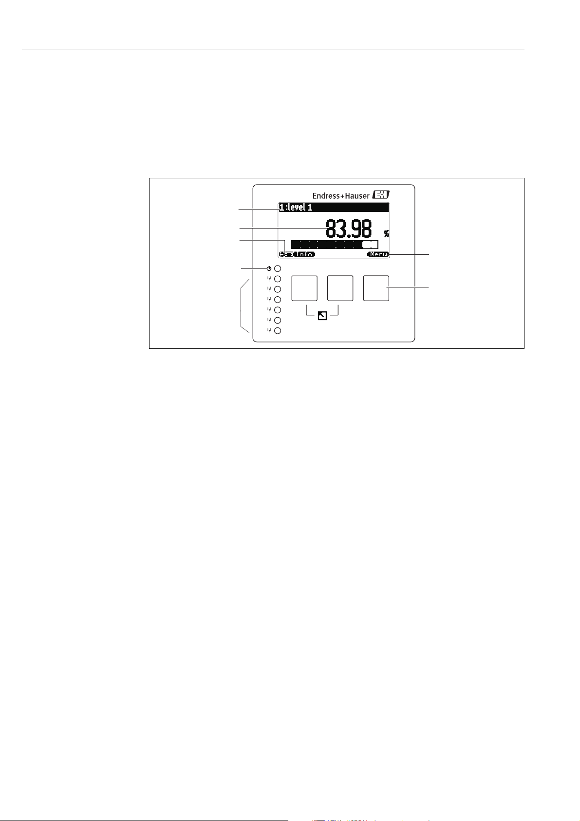
1.1.1 Display and operating elements
1 Softkey symbol
2Key
3 LEDs indicating the switching states of the relays
4 LED indicating the operating state
5 Display symbols
6 Value of the parameter, including unit
7 Name of the parameter
L00-FMU90xxx-07-00-00 -xx-002
4
Page 5

Display symbols
Symbol Meaning
Operating mode of the instrument
User
User parameters can be edited. Service parameters are locked.
Diagnosis
The service interface is connected.
Service
User and service parameters can be edited.
Locked
All parameters are locked.
Locking state of the currently displayed parameter
Display parameter
The parameter can not be edited in the current operating mode of the instrument.
Editable parameter
The parameter can be edited.
Scroll symbols
Scroll list available
Indicates that the list contains more parameters than can be represented on the display. By pressing
V or W repeatedly, all parameters of the list can be accessed.
Navigation in the envelope curve display
Move left
Notes on use
Move right
Zoom in
Zoom out
LEDs
LED indicating the operating state (pos. 4 in the figure)
green normal measuring mode; no error detected
Warning:
red (flashing)
red
off supply voltage missing
LEDs for the relays (pos. 3 in the figure)
yellow The relay is activated.
off The relay is de-activated (idle state).
An error is detected but the measurement continues. Reliability of the measured value is no longer
ensured.
Alarm:
An error is detected. The measurement is interrupted. The measured value assumes the value
specified by the user (parameter "output on alarm").
5
Page 6
Notes on use
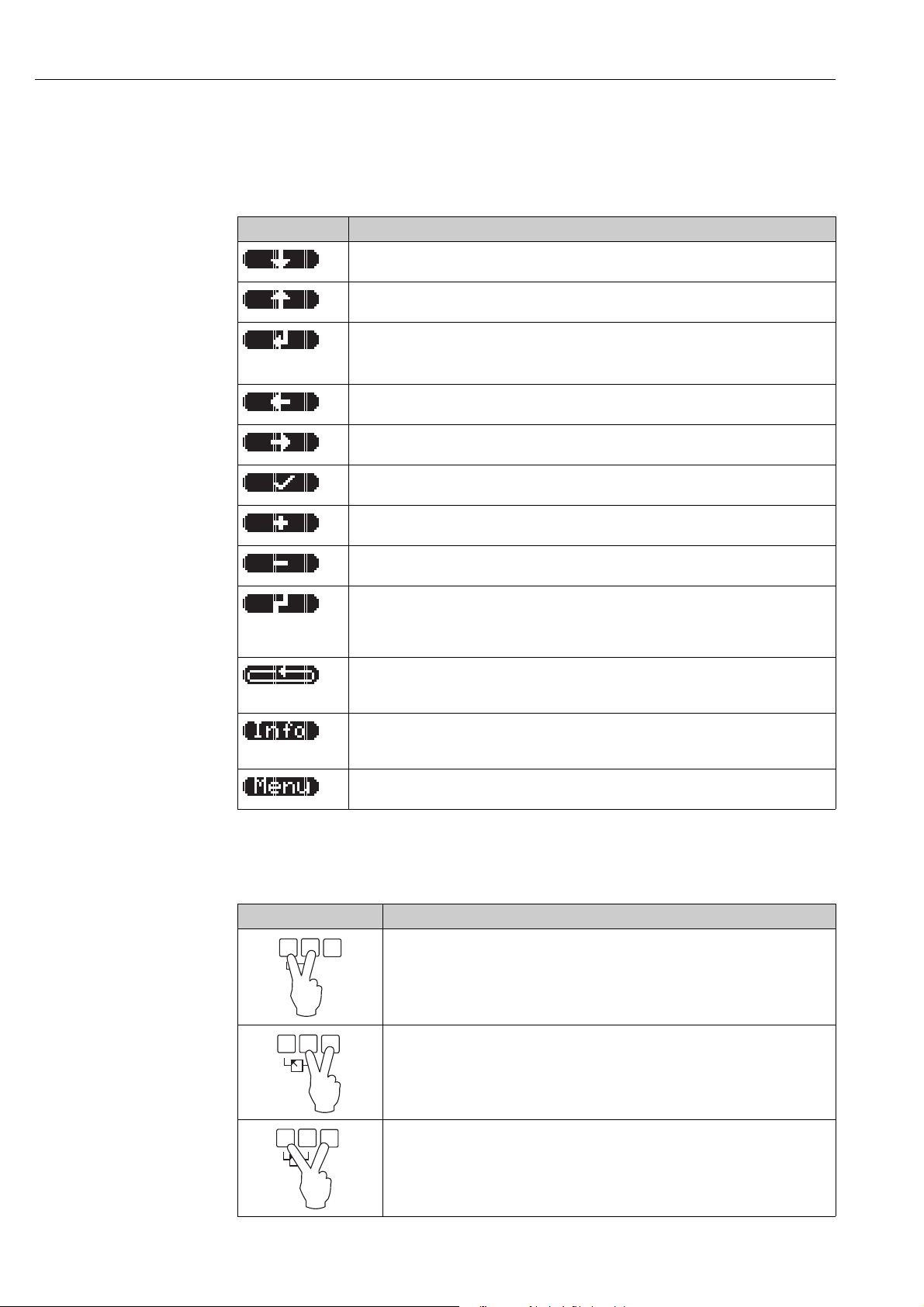
Keys (softkey operation)
The function of the keys depends on the current position within the operating menu (softkey functionality). The key functions are indicated by softkey symbols in the bottom line of the display.
Symbol Meaning
Move downwards
Moves the marking bar downwards within a selection list.
Move upwards
Moves the marking bar upwards within a selection list.
Enter
• Opens the marked submenu, the marked parameter set or the marked parameter
• Confirms the edited parameter value
Previous parameter set
Reopens the previous parameter set within the submenu.
Next parameter set
Opens the next parameter set within the submenu.
Confirm selection
Selects the option of a selection list which is currently marked by the bar.
Increase value
Increases the active digit of an alphanumeric parameter.
Decrease value
Decreases the active digit of an alphanumeric parameter
Error list
Opens the list of all errors which are currently detected.
If a warning is present, this symbol flashes.
If an alarm is present, the symbol is displayed continuously.
Change Display
Change to the next page of measured values (only available if more than one pages of measured
values have been defined; ä 148, The "display" menu)
Info
Opens the Shortcut Menu, which contains the most important information about the current state
of the instrument
Menu
Opens the Main Menu, which contains all parameters of the Prosonic S
General key combinations
The following key combinations do not depend on the menu position:
Key combination Meaning
Escape
• While editing a parameter: Exit the editing mode without accepting the changes.
• Within the navigation: Move upwards to the previous layer of the menu.
Increase contrast
Increases the contrast of the display module.
Decrease contrast
Decreases the contrast of the display module.
6
Page 7
Notes on use
32
1
Key combination Meaning
Locking
Locks the instrument against parameter changes.
The instrument can only be unlocked again by the keys.
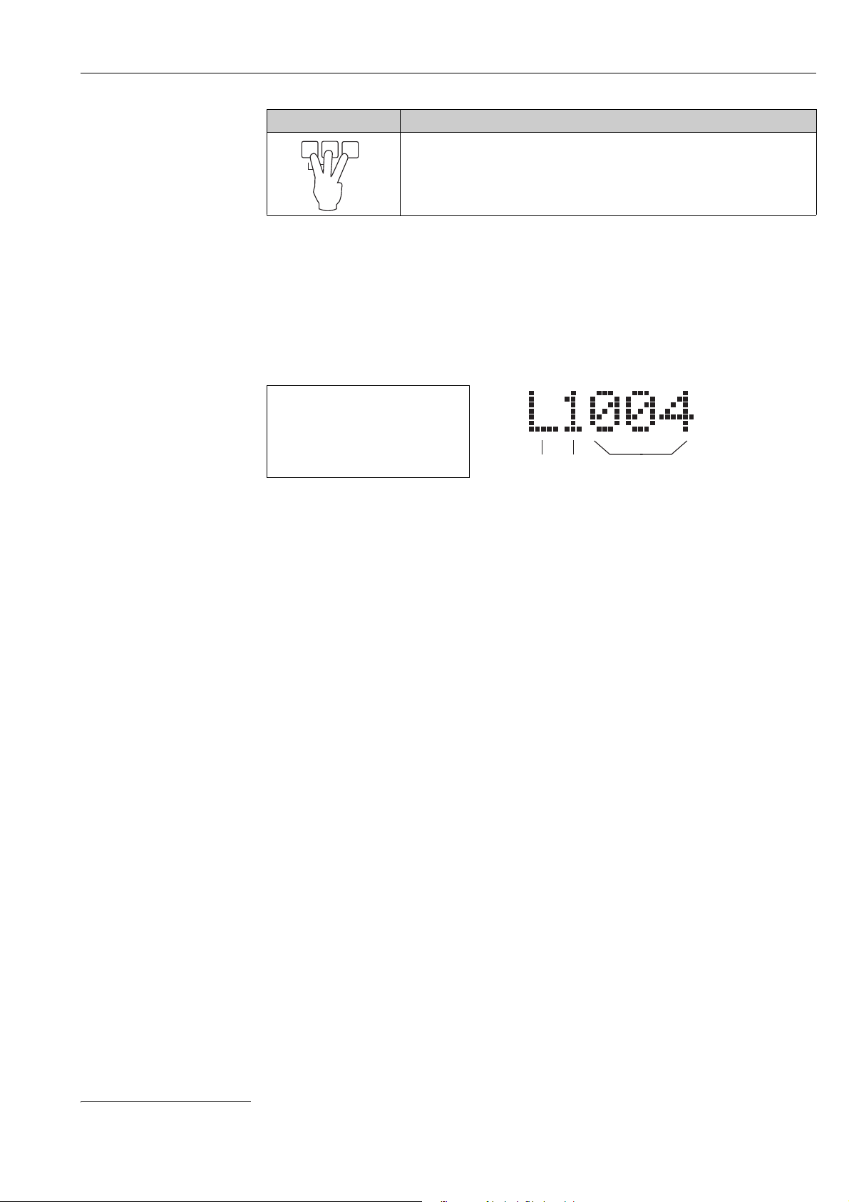
1.1.2 The operating menu
Structure of the menu
The parameters of the Prosonic S are organized in an operating menu (consisting of a main menu
and several submenus). Parameters which are related to each other are comprised in a common
parameter set. To simplify the navigation within the menu, a five-digit position code is displayed
with each parameter set.
LVL 1 appl.para L1004
tank shape :dome ceiling
medium property:liquid
process cond:standard liq.
Identification of the parameter sets:
1Submenu
2 Number of the associated input or output
3 Number of the parameter set within the submenus
•The first digit (1) specifies the submenu
1)
:
– L: "level"
– F: "flow"
– A: "safety settings"
– R: "relay/controls"
– O: "output/calculations"
– D: "device properties", "calibr. display" and "sensor management"
– I: "system information"
– S: "service" (only available if the service password has been entered)
Diagrams of the submenus can be found in the Chap. 12, "Operating menu".
•The second digit (2) is used if the parameter set occurs several times within the Prosonic S (e.g.
for different inputs or outputs).
Example:
– O1201: "allocation current" for output 1
– O2201: "allocation current" for output 2
If the parameter set occurs only once wihtin the Prosonic S, "X" is indicated at this position.
•The last three digits (3) specify the individual parameter sets within the submenu.
1) Depending on the instrument version, the installation environment and the selected operating mode, some of the submenus may not be present.
7
Page 8
Notes on use
Parameter types
Display parameters
Editable parameters
L00-FMU90xxx-07-00-00-e n-041
L00-FMU90xxx-07-00-00-e n-044
Parameters for which the symbol is displayed in the left bottom corner of the display
module, are either locked or display-only parameters.
Parameters, for which the symbol is displayed in the left bottom corner of the display
module, can be entered for editing by pressing
.
The editing procedure depends on the type of
parameter:
• when entering a selection parameter, the
associated selection list appears (see below:
"Editing a parameter with selection list").
• when entering a numerical or alphanume-
rical parameter, the text and number editor
appears (see below: "Entering numbers and
characters").
8
Page 9
CX001
main menu
level
flow
safety settings
ralay/controls
…
LX001
level
L1002
level 1
Return
input: sensor 1
sensor sel.: autom.
detected: FDU91
tank shape: dome
medium proper: liq.
proc. cond.: stand.
5.00 m
level (LVL) 1
...
...
basic setup
extended calibr.
simulation
L1004
LVL1 appl. para
tank shape: dome
medium proper: liq.
proc. cond.: stand.
L100A
tank shape
dome ceiling
horizontal cyl.
bypass
stilling well
L1004
LVL1 appl. para
L100A
tank shape
dome ceiling
horizontal cyl.
bypass
stilling well
L1004
LVL1 appl. para
tank shape: bypass
medium proper: liq.
proc. cond.: stand.
L1004
LVL1 appl. para
tank shape: bypass
medium proper: liq.
proc. cond.:stand.
L1005
LVL1 empty cal.
level 1
67.60 %
=
L1003
LVL1 sensor sel.
Menu
Main Menu
Submenus
Parameter Set
(here: with 3 parameters)
Editing a
parameter with
selection list
Notes on use
Navigation within the menu (Example)
L00-FMU90xxx-19-00-00-en-050
9
Page 10
Notes on use
shortcut menu main menu
actual error
daily counter*
level
Warning 01802
flow
Alarm 01502
tag marking
envelope curve
language
device information
password/reset
* for flow measurements only
...
...
...
...
1
2
3
4
5
6
FMU90
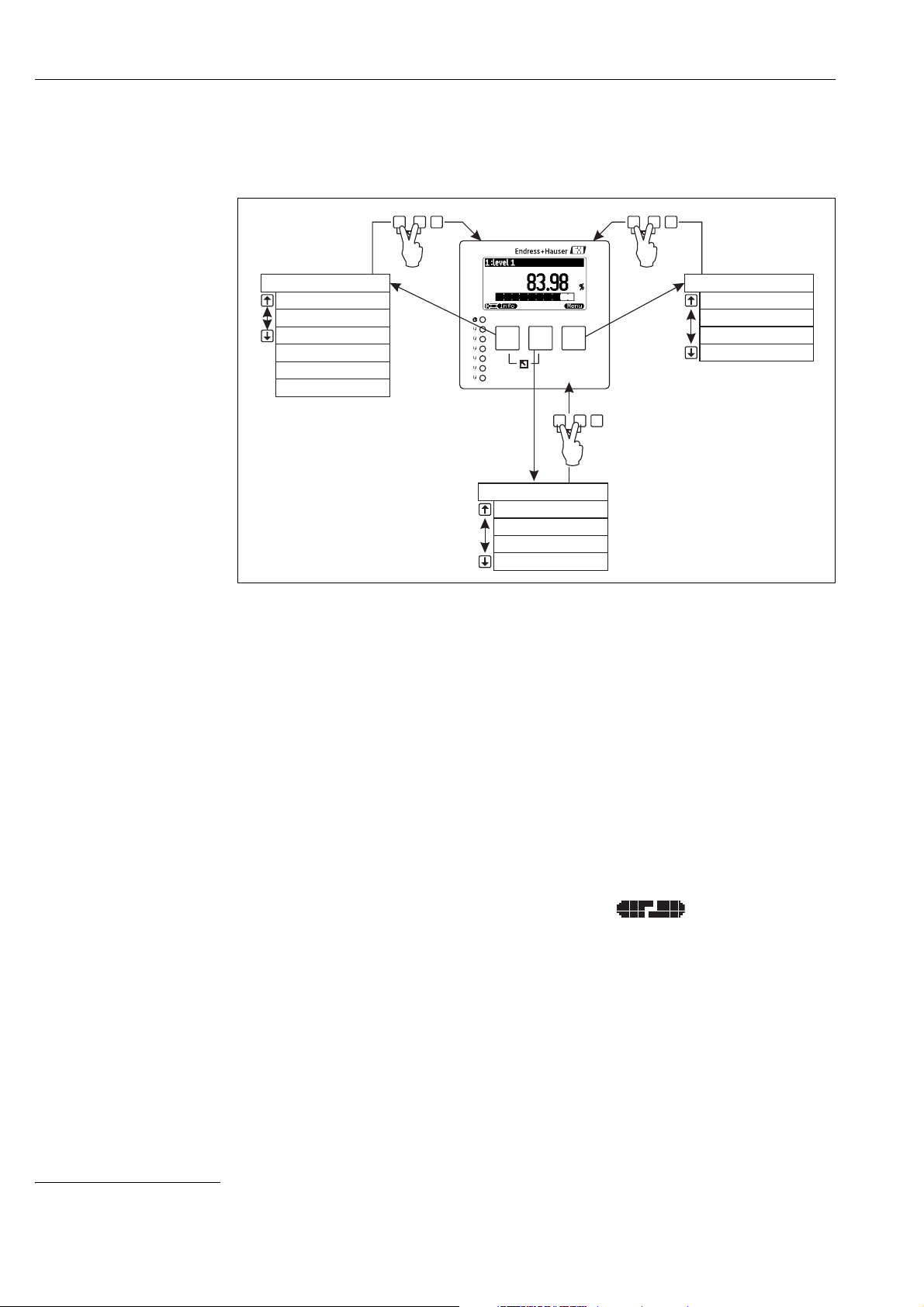
Entering the menu
The navigation always starts from the main screen (measured value display
lowing menus can be opened by the keys:
2)
). From there, the fol-
• shortcut menu
The shortcut menu is accessed via the "Info" key. It allows quick access to device information:
– daily counter (for flow measurements)
–tag marking
– envelope curve: used to check the signal quality
– language: sets the display language
– device information: serial number, versions of software and hardware
– password/reset: used to enter the password or reset code
All parameters of the shortcut menu are contained in the main menu as well.
• main menu
The main menu is accessed via the "Menu" key. It contains all parameters of the Prosonic S. It
is divided into submenus. Some of the submenus consist of further submenus. Which submenus
are actually present, depends on the instrument version and the installation environment.
An overview of all submenus and parameters is given in the Chap. 12, "Operating menu".
• actual error
If the self-monitoring of the Prosonic S detects an error, the softkey symbol appears
above the middle key.
If the softkey symbol flashes, only "warnings"
If the softkey symbol is displayed permanently, at least one "alarm
After pressing the key, a list of all currently present errors appears.
3)
are present.
"
is present.
L00-FMU90xxx-19-00-00-yy-038
2) Note: Depending on the configuration, the appearance of the measured value display may be differemt from the example in the figure.
3) The difference between"Warning" and "Alarm" Chap. 13.3
10
Page 11

Selecting a submenu
1.
2.
3.
main menu
“device properties”
submenu
“distance unit”
parameter set
Notes on use
1. In the main menu, press W or V until the
required submenu is marked by the bar.
Note!
!
The symbols indicate that the
selection list contains more items than can be
displayed on the module. Press W or V several
times, to mark one of the hidden items.
2. Press , in order to enter the marked
submenu.
3. If the submenu contains further submenus,
continue until you reach the level of the
parameter sets. This level is reached if the
softkey symbols U and T appear.
L00-FMU90xxx-19-00-00-yy-039
!
Note!
If necessary, you can return to the previous level of the menu by pressing .
11
Page 12
Notes on use
1.
1.
3.
2.
4.
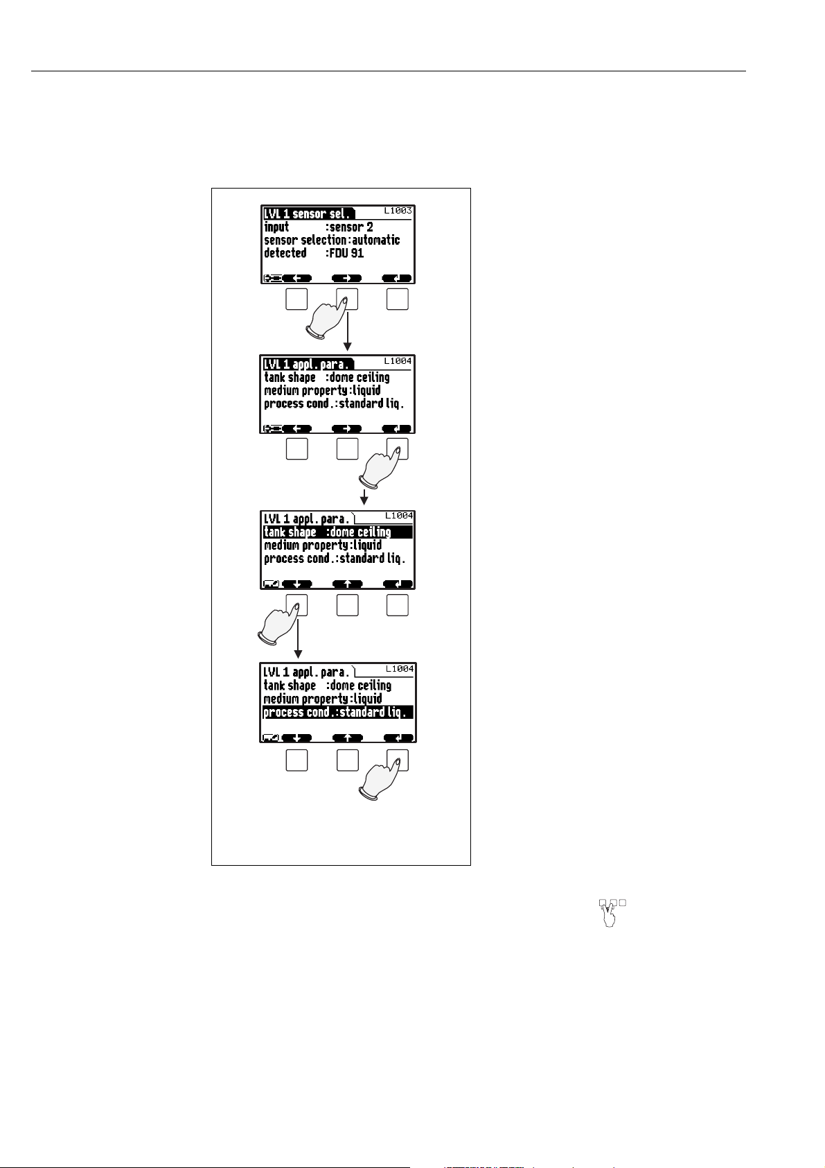
Selecting a parameter
By pressing U or T you can switch between the parameter sets of the current submenu. For each
parameter set the values of all its parameters are displayed. In order to change one of the values,
proceed as follows:
1. Press U or T, until you have reached the
required parameter set.
2. Press , in order to enter the parameter set.
3. Select the required parameter by pressing
W or V.
(This step is not required if the set contains
only one parameter.)
4. Press , in order to enter the editing mode
of the parameter.
The editing method depends on the type of
parameter (selection list, numeric or
alphanumeric parameter). For details refer
to the following sections.
!
Note!
If necessary, you can exit the parameter and parameter set by pressing .
L00-FMU90xxx-19-00-00-e n-040
12
Page 13
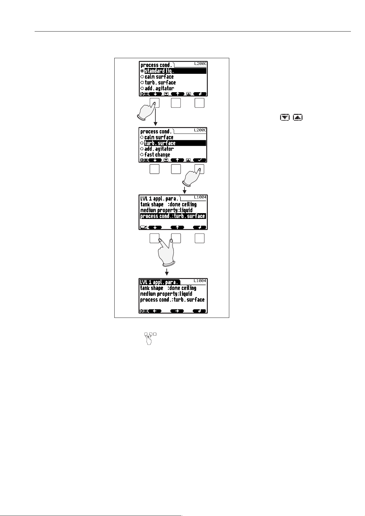
Editing a parameter with selection list
1.
2.
3.
Notes on use
1. Press W or V, until the required option is
marked by the bar (in the example: "turb.
surface").
Note!
!
The symbols indicate that the
selection list contains more items than can
be displayed on the module. Press W or V
several times, to mark one of the hidden
items.
2. Press ✓, in order to select the marked
option. It is then stored in the instrument.
3. Press the left and middle keys
simultaneously in order to quit the
parameter.
The software key symbols U and T
reappear and you can switch to the next
parameter set.
!
Note!
By pressing before ✓ you can quit the parameter without accepting your changes.
L00-FMU90xxx-19-00-00-en-041
13
Page 14

Notes on use
1.
2.
3.
4.
5.
6.
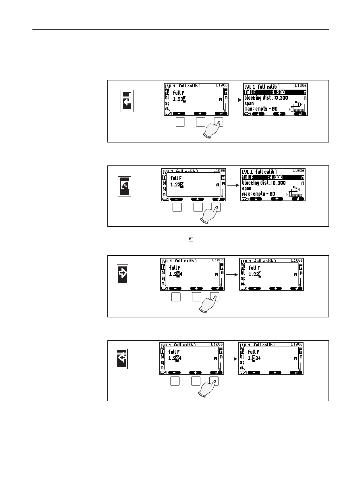
Entering numbers and characters
When you select a numeric parameter ("empty
calibration", "full calibration" etc.) or an alphanumeric parameter ("device marking" etc.), the
editor for numbers and text strings appears.
Enter the desired value in the following way:
1. The cursor is at the first digit. Press S or O
until this digit has the required value.
jump to the next digit.
3. Repeat the procedure for all relevant digits.
2. Press in order to confirm the value and to
4. If all relevant digits have been entered:
Press S or O, until appears at the cursor.
14
5. Press to store the complete value in the
device.
6. Press the left and middle keys simultaneously in order to quit the parameter.
L00-FMU90xxx-19-00-00-yy-042
Page 15
Notes on use
Special editing functions
Within the editor for alphanumeric characters, pressing S or O does not only lead to numbers and
characters but also to the following symbols for special editing functions. They simplify the editing
procedure.
L00-FMU90xxx-19-00-00-yy-043
Enter: The number left of the cursor is transferred to the instrument.
L00-FMU90xxx-19-00-00-yy-044
Escape: The editor is closed. The parameter maintains its former value. The same behavior can be achieved by pressing
the left and the middle key simultaneously ( ).
L00-FMU90xxx-19-00-00-yy-045
Next digit: The cursor moves on to the next digit.
Previous digit: The cursor moves back to the previous digit.
L00-FMU90xxx-19-00-00-yy-046
15
Page 16
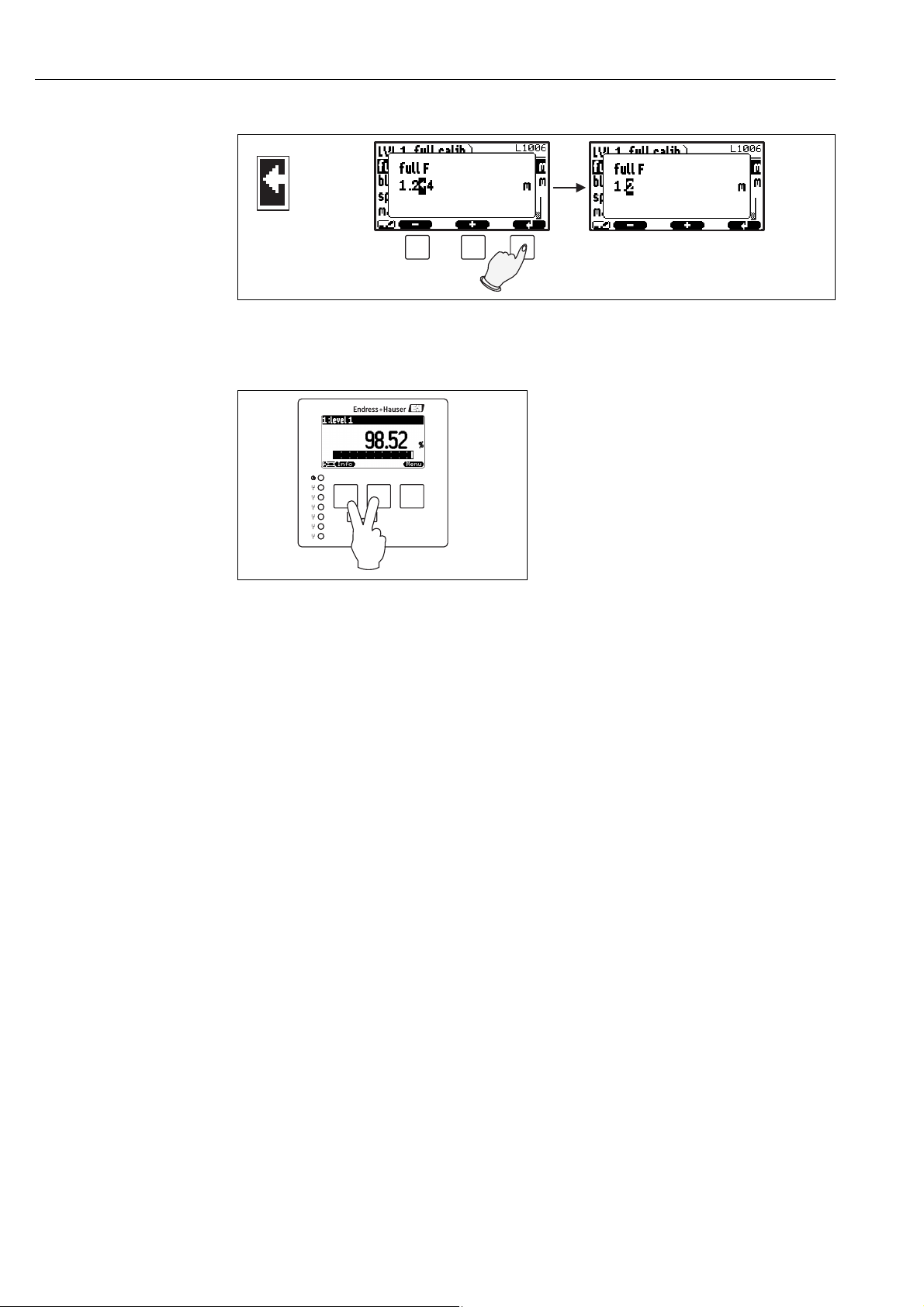
Notes on use
1
2
3
4
5
6
FMU90
L00-FMU90xxx-19-00-00-yy-047
Delete: The current digit and all digits to its right are deleted.
Return to the measured value display
By pressing the left and middle keys
simultaneously you can return
• from a parameter to the parameter set
• from the parameter set to the submenu
• from the submenu to the main menu
• from the main menu to the measured value
display
L00-FMU90xxx-19-00-00-e n-048
16
Page 17

1.2 First setup
Notes on use
!
Note!
This chapter describes the commissioning of the Prosonic S via the display and operating module.
Commissioning via FieldCare or the Field Xpert SFX100 is similar. For further instructions refer to
the FieldCare Online Help or the Operating Instructions supplied with the Field Xpert SFX100.
After switching on the power supply for the first time, the instrument asks for a number of operating
parameters:
1. Select the display language.
a. Press or to move the marking bar to the
desired language.
b. Press to confirm your selection.
L00-FMU90xxx-07-00-00-yy-027
2. Select the unit for distance measurements.
L00-FMU90xxx-07-00-00-en-028
3. Select the temperature unit.
!
L00-FMU90xxx-07-00-00-en-029
4. Select the operating mode.
Note!
!
The available options depend on the instrument
version and the installation environment.
L00-FMU90xxx-07-00-00-en-030
5. For level measurements:
Select the control functions, which you are going
to use.
L00-FMU90xxx-07-00-00-en-031
Note!
By pressing you can return to the previous parameter (e.g. in order to correct the value).
All these parameters can also be changed at a later point of time in the "device properties/operating
parameters" and "device properties/language" parameter sets.
17
Page 18
The "level" menu
2 The "level" menu
level LX001
level (LVL) 1
level (LVL) 2
"level" selection list
Use this list to select the level channel you are going to configure.
2.1 The "basic setup" submenu
2.1.1 "LVL N sensor selection" (N = 1 or 2)
LVL1 sensor sel. L1003
input:
sensor selection:
detected:
"input"
Use this parameter to assign a sensor to the channel.
!
"
Selection:
•no sensor
•sensor 1
• sensor 2 (only for 2-channel instruments)
"sensor selection"
Use this parameter to specify the type of the connected ultrasonic sensor.
Note!
• For the sensors FDU9x the option "automatic" is recommended (default setting). With this setting
the Prosonic S recognizes the type of sensor automatically.
• For the sensors FDU8x the type has to be assigned explicitly. The automatic sensor recognition
does not work for these sensors.
Caution!
After exchanging a sensor, observe the following:
The automatic sensor recognition is also active after a sensor has been exchanged
recognizes the type of the new sensor automatically and changes the "detected" parameter if
required. The measurement continues without a break.
Nevertheless, in order to ensure perfect measurement, the following checks are required:
•Check the "empty calibration" and "full calibration" parameters. Adjust these values if
required. Take into account the blocking distance of the new sensor.
•Go to the "distance correction" parameter set and check the displayed distance. If required,
perform a new interference echo suppression.
4)
. The Prosonic S
"detected" (only available for "sensor selection" = "automatic")
Indicates the type of the automatically detected sensor.
4) if the new sensor is of the type FDU9x
18
Page 19

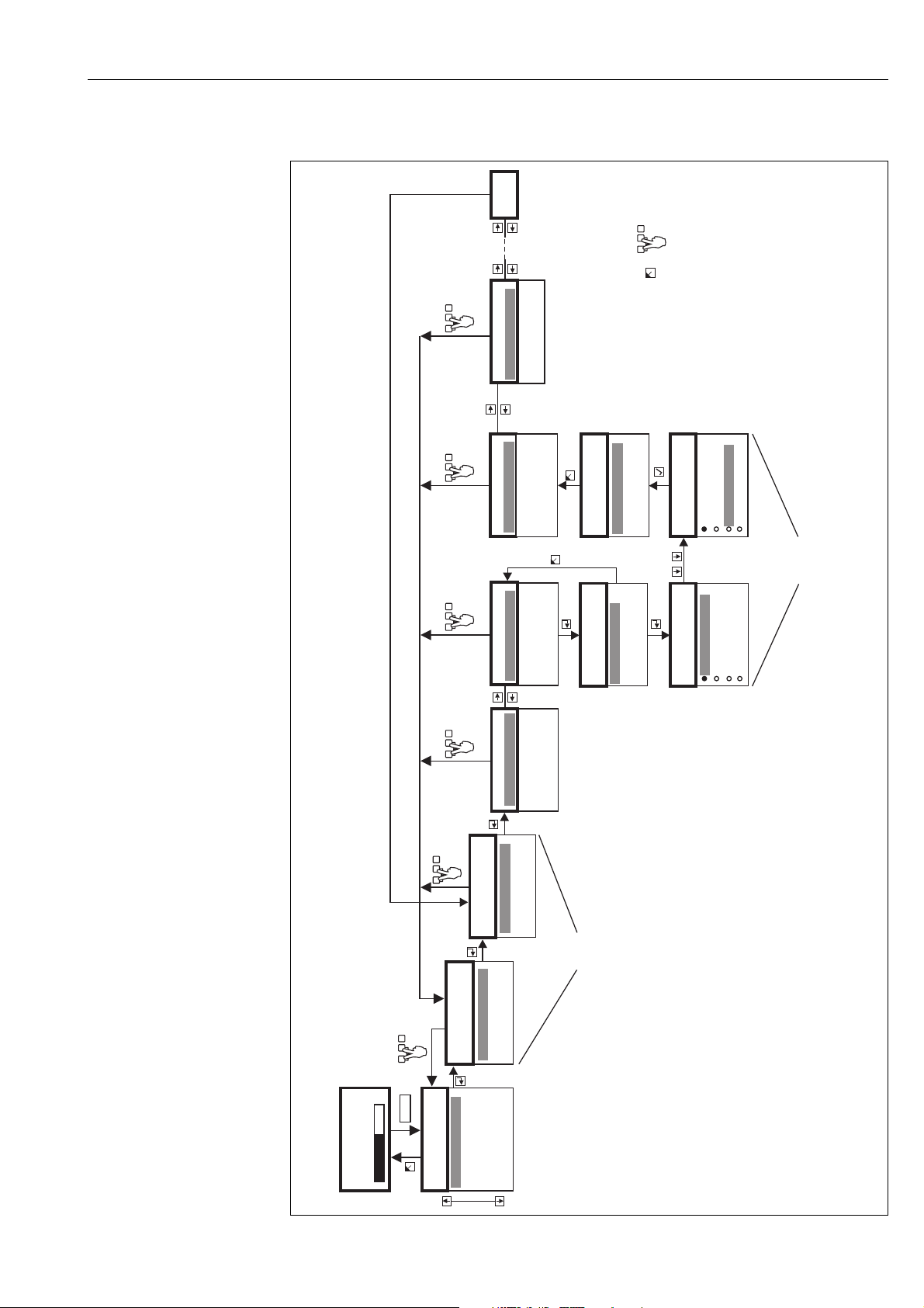
2.1.2 "LVL N application parameters" (N = 1 or 2)
A
BC
D
E
F
LVL1 appl. para. L1004
tank shape:
medium property:
process cond.:
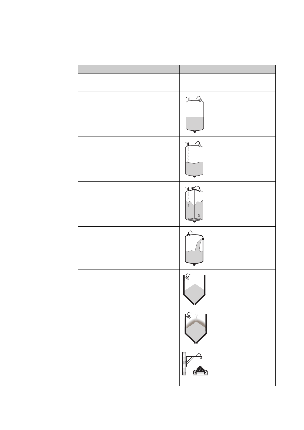
"tank shape"
Use this parameter to specify the tank shape of your application.
Selection:
The "level" menu
L00-FMU90xxx-14-00-00-xx-002
A Dome ceiling
B Horizontal cyl.
C Bypass, stilling well/ultrasonic guide pipe
D No ceiling, e.g. dumps, open levels, chanels, weirs
E Sphere
F Flat ceiling
"medium property"
Use this parameter to specify the type of medium.
!
Selection:
• liquid
• paste like
• solid < 4 mm
• solid > 4 mm
• unknown
Note!
If the medium does not fit into one of the groups, select "unknown".
19
Page 20
The "level" menu
"process conditions"
Use this parameter to specify the process conditions of your application. The filters of the signal
evaluation are automatically adjusted to the selected conditions.
"process conditions" for the following situations Example filter settings
standard liquid for all fluid applications which do
not fit in any of the following
groups
calm surface Storage tanks with immersion
tube or bottom filling
The filters and output damping are set
to average values.
The averaging filters and output
damping are set to large values.
-> stable measured value
-> accurate measurement
-> slow reaction time
turbulent surface Storage/accumulation tanks with
uneven surface due to free filling,
mixing nozzles or small bottom
stirrers
additional agitator Moving surfaces (possibly with
vortex formation) due to agitators
fast change Rapid level change, particularly in
small tanks
standard solid For all bulk solid applications
which do not fit in any of the
following groups.
Special filters for stabilizing the input
signal are activated.
-> stable measured value
-> medium reaction time
Special filters for stabilizing the input
signal are set to large values.
-> stable measured value
-> medium reaction time
The averaging filters are set to small
values.
-> rapid reaction time
-> possibly unstable measured value
The filter and output damping are set
to average values.
20
solid dusty Dusty bulk solids The averaging filters are set to detect
even relatively weak signals.
conveyor belt Bulk solids with rapid level change The averaging filters are set to small
values.
-> rapid reaction time
-> possibly unstable measured value
test: no filter For service and diagnosis only All filters are switched off.
Page 21
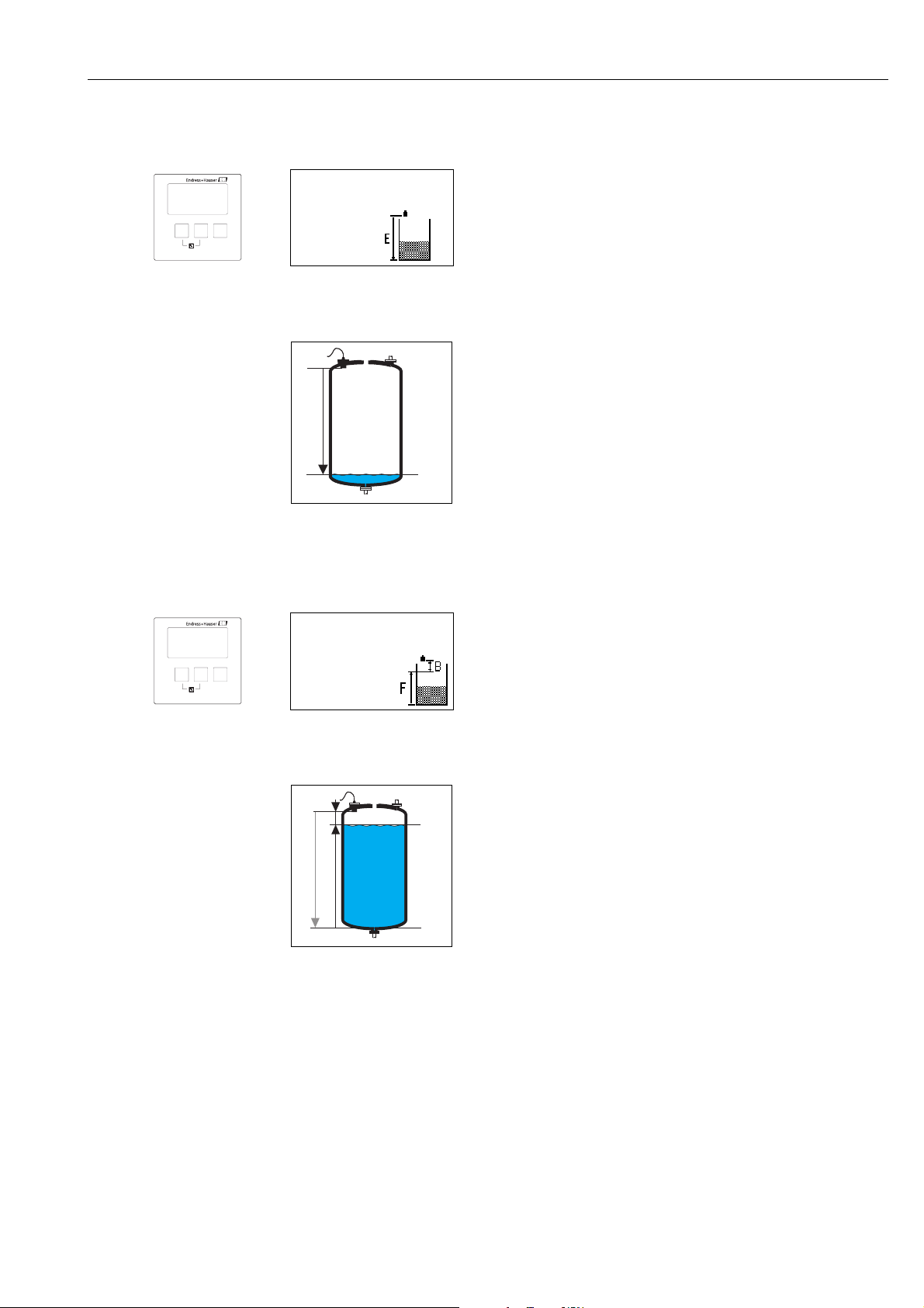
2.1.3 "LVL N empty calibration" (N = 1 or 2)
0/4 mA
0%
E
20 mA
100%
0/4 mA
0%
BD
F
E
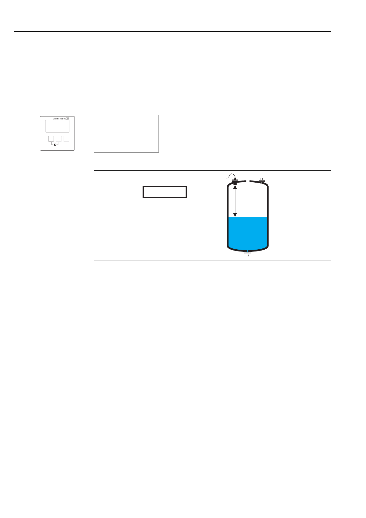
LVL1 empty cal. L1005
empty E: 0,00 m
"empty E"
Use this parameter to specify the empty distance E, i.e. the
distance between the reference point of the sensor and the
minimum level (zero point).
– Default: max. measuring range of the respective sensor
– Range of values: depending on sensor type
Caution!
"
The zero point should not be deeper than the point at which the
L00-FMU90xxx-19-00-00 -yy-007
ultrasonic wave impinges on the tank bottom
The "level" menu
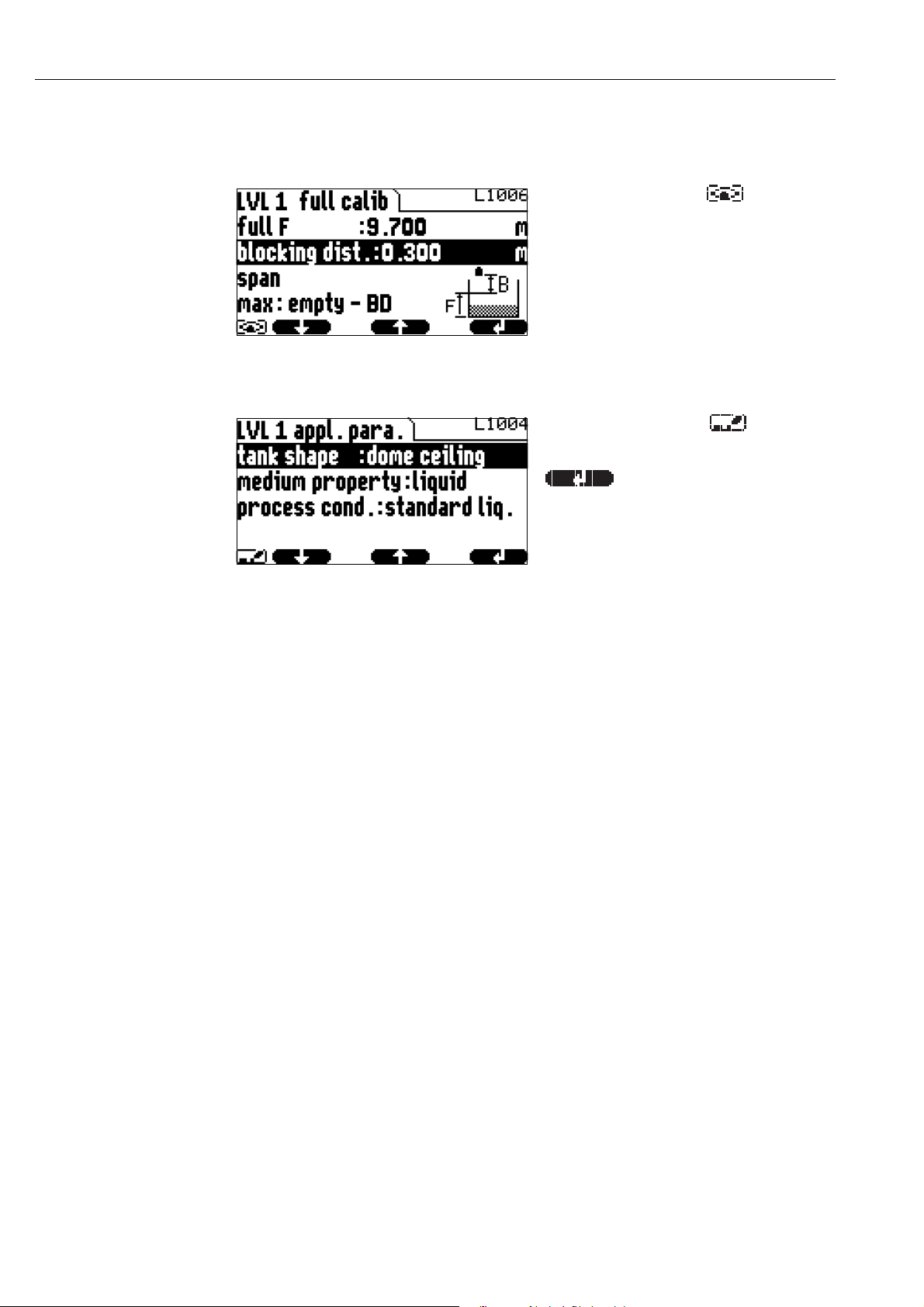
2.1.4 "LVL N full calibration" (N = 1 or 2)
LVL1 full calib. L1006
full F: 0,00 m
block.dist. BD:
"full F"
Use this parameter to specify the span F, i.e. the distance from the
minimum level to the maximum level.
– Default setting: depending on sensor type
– Range of values: depending on sensor type
– blocking distance BD: depending on sensor type (see table)
Caution!
"
The maximum level may not project into the blocking distance:
L00-FMU90xxx-19-00-00 -yy-008
F
max
= E - BD
21
Page 22

The "level" menu
"blocking distance"
Indicates the blocking distance of the respective sensor. The blocking distance is measured from the
reference point of the sensor.
Type of sensor Blocking distance (BD) Maximum measuring distance
FDU90 0.07 (0.2) 3.0 (9.8) (for liquids)
FDU91/FDU91F 0.3 (1.0) 10 (33) (for liquids)
FDU92 0.4 (1.3) 20 (66) (for liquids)
FDU93 0.6 (2.0) 25 (82) (for liquids)
FDU95 - *1*** (low temperature version) 0.7 (2.3) 45 (148) (for solids)
FDU95 - *2*** (high temperature version) 0.9 (3.0) 45 (148) (for solids)
FDU96 1.6 (5.2) 70 (230) (for solids)
FDU80/FDU80F 0.3 (1.0) 5 (16) (for liquids)
FDU81/81F 0.5 (1.6) 10 (33) (for liquids)
FDU82 0.8 (2.6) 20 (66) (for liquids)
FDU83 1.0 (3.3) 25 (82) (for liquids)
FDU84 0.8 (2.6) 25 (82) (for solids)
FDU85 0.8 (2.6) 45 (148) (for solids)
FDU86 1.6 (5.2) 70 (230) (for solids)
m (ft)
1) valid for optimum process conditions
1)
2.1.5 "LVL N unit" (N = 1 or 2)
LVL 1 unit L1007
unit level:
level 1:
distance:
"unit level"
Use this parameter to select the level unit.
If no linearization is performed, the level is displayed in this unit.
Selection:
•m
•ft
•inch
•mm
• % (Default)
Caution!
"
After a change of the level unit, the switching points of the limit and pump control relays have to
be checked and to be adjusted if required.
22
Page 23
The "level" menu
0/4 mA
0%
F
D
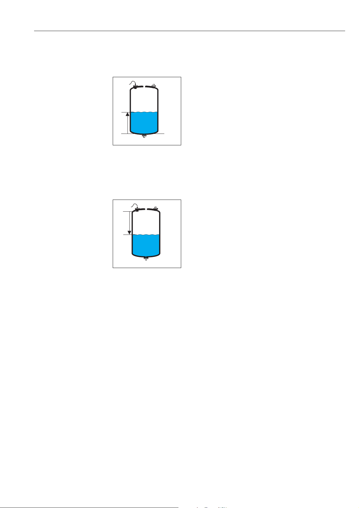
"level N" (N = 1 or 2)
Displays the currently measured level F (from the zero point to the product surface) in the selected
unit.
L00-FMU90xxx-19-00-00-yy-021
"distance"
Displays the currently measured distance D (from the reference point of the sensor to the product
surface) in the distance unit. If the display value does not match the real distance, an interference
echo suppression must be performed prior to linearization.
!
L00-FMU90xxx-19-00-00-yy-022
Note!
The distance unit is defined during the first setup of the instrument. If required, it can be changed
in the "device properties/operating params" menu.
23
Page 24
The "level" menu
100%
20
mA
0%
0/4
mA
(a)
kg
m
ft
3
3
100%
20
mA
0%
0/4
mA
(D)Ø
(a)
kg
m
ft
3
3
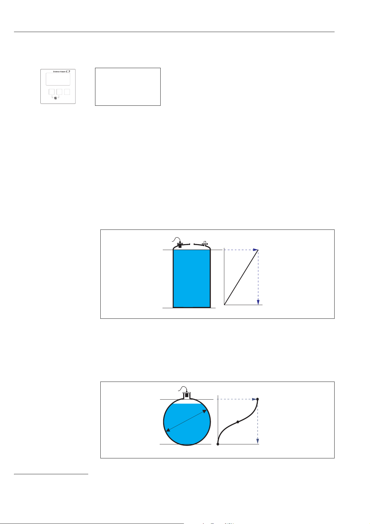
2.1.6 "LVL N linearisation" (N = 1 or 2)
LVL 1 linearisat. L1008
type:
mode:
Note!
!
Number and type of the parameters in this set depend on the
selected linearization type.
Only the parameters "type" and "mode" are always present.
The "linearization" is used to convert the level into other quantities. Especially, it can calculate the
volume or mass within a vessel of arbitrary shape. The Prosonic S provides different linearization
modes for the most common types of vessels. Additionally, a linearization table for arbitrarily shaped
vessels can be entered.
"type"
Use this parameter to select the type of linearisation.
Selection:
• none
In this linearization type the measured level is not converted but displayed in the selected level
unit (see above, "unit level").
• linear
In this linearization type the displayed value is proportional to the measured level.
The following additional parameter have to be specified:
– the unit for the linearized value, e.g. kg, m
3
, ft3, ... ("customer unit")
– the maximum capacity (a) of the vessel, measured in the customer unit ("maximum scale").
• horizontal cylinder
5)
• sphere
In these linearization types the measured level is convertet to the volume in a horizontal cylinder
or a spherical tank.
5) This option is only valid for horizontal cylinders without dome ceiling. For tanks with dome ceiling FieldCare can be used to calculate a linearisation table and
to upload it into the instrument.
24
Page 25
The "level" menu
100%
20
mA
0%
0/4
mA
= kg,m3,ft3, ...
H
(a)
A
B
100%
20
mA
0%
0/4
mA
kg
m
ft
3
3
The following additional parameters have to be specified:
– the unit of the linearized value, e.g. kg, m
3
, ft3, ... ("customer unit")
– the diameter (D) of the tank ("diameter")
– the maximum capacity (a) of the tank, measured in the customer unit ("maximum scale").
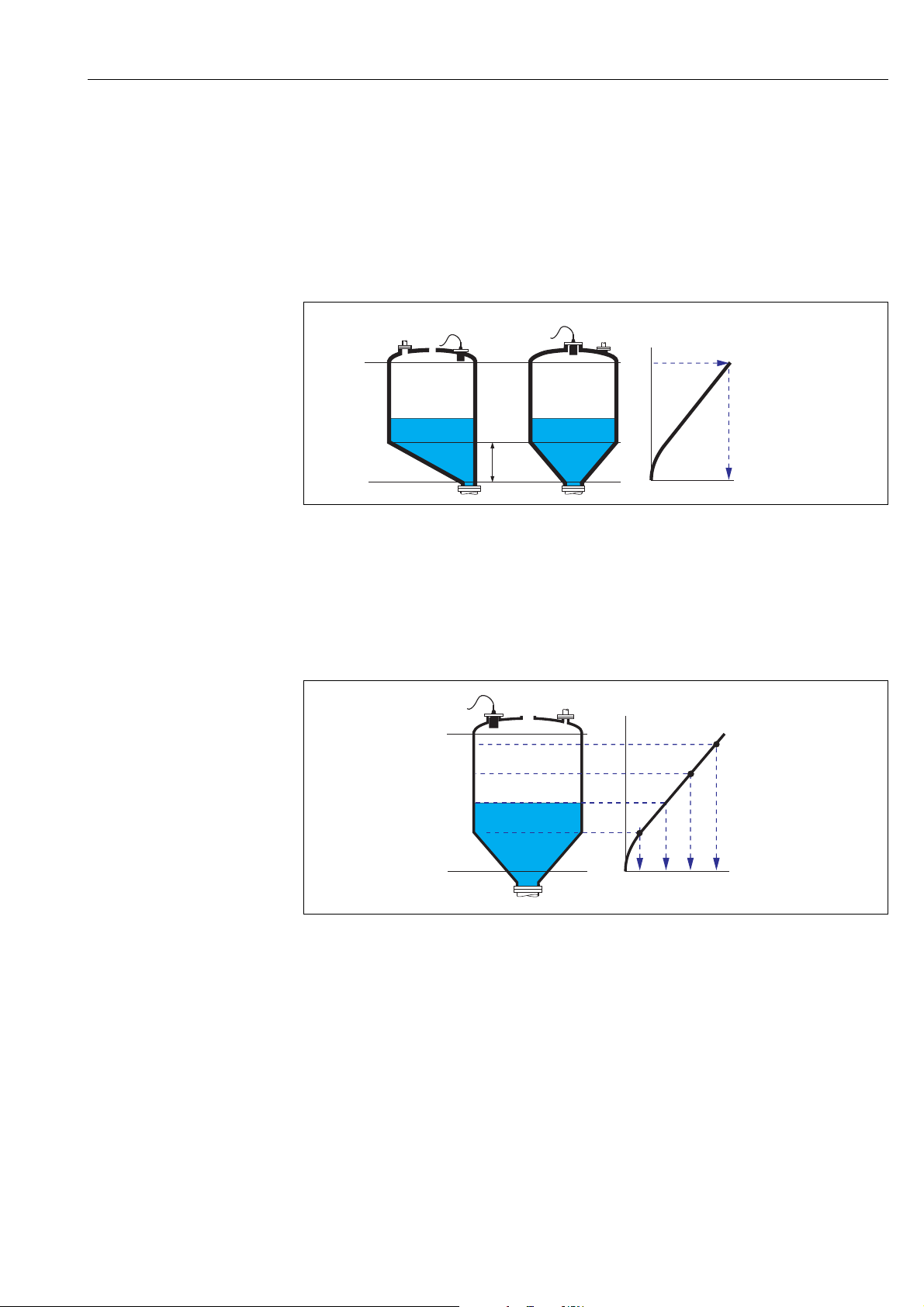
• angled bottom (A)
• pyramid bottom (B)
• conical bottom (B)
In these linearisation modes the measured level is converted to the volume in the respective type
of vessel.
The following additional parameters have to be specified:
– the unit for the linearized value, e.g. kg, m
3
, ft3, ... ("customer unit")
– the intermediate height H according to the diagram ("intermediate height")
– the maximum capacity (a) of the tank, measured in the customer unit ("maximum scale").
• table
In this linearization mode the measured value is calculated from a linearization table. The table
may consist of up to 32 pairs of values (level - volume). The table must be monotonically
increasing or decreasing.
The following additional parameters have to be specified:
– the unit of the linearized value, e.g. kg, m
3
, ft3, ... ("customer unit")
– the linearization table ("edit")
"customer unit"
3
Use this parameter to select the desired unit for the linearized values (e.g. kg, m
, ft3, ...). This unit
is only indicated on the display. It does not cause a conversion of the measured value.
!
Note!
After selecting the option "customer specific", the parameter "customized text" appears. An arbitrary
string (consisting of up to 5 alphanumeric characters) can be entered into this parameter.
"maximum scale"
Use this parameter to specify the maximum content of the vessel in the customer unit.
25
Page 26

The "level" menu
100%
20
mA
0%
0/4
mA
A
B
"diameter"
Use this parameter to specify the diamter of the horizontal cylinder or the spherical tank
respectively.
"intermediate height"
Use this parameter to specify the intermediate height of the vessel.
"mode"
Use this parameter to specify if the measurement
refers to the "level" (A) or to the "ullage" (B).
L00-FMU90xxx-19-00-00-yy-015
"edit"
Use this parameter to enter, change or read a linearization table. There are the following options:
• read:
The table editor is opened. The existing table can be read but not changed.
• manual:
The table editor is opened. Table values can be entered and changed.
• semi-automatic:
The table editor is opened. The level is automatically read by the Prosonic S. The measured value
(volume, weight or flow) must be entered by the user.
• delete:
The linearization table is deleted.
26
Page 27
The table editor
No.
Level
Value
1
0,0000
0,0000
2
0,0000
0,0000
3
0,0000
0,0000
…
0,0000
0,0000
: go to next row
: go to previous row
: open marked row
for editing
No.
Level
Value
1
0,0000
0,0000
2
0,0000
0,0000
3
0,0000
0,0000
…
0,0000
0,0000
: navigate within the table
: (for "Level" und "Value”)
open marked number
for editing
: (for "No.")
open row editor
Row function
(before current row)
Query: new position
Return to the previous
step by this
key combination.
- Delete row
- Insert row
- Move row
A
B
(a) (a)
(b)
(c)
C
(a)
(b)
The "level" menu
L00-FMU90xxx-19-00-00-de-006
"status table"
Use this parameter to enable or disable the linearization table.
Selection:
• enabled
The table is used.
• disabled
The table is not used. The measured value is transferred to the output without linearization.
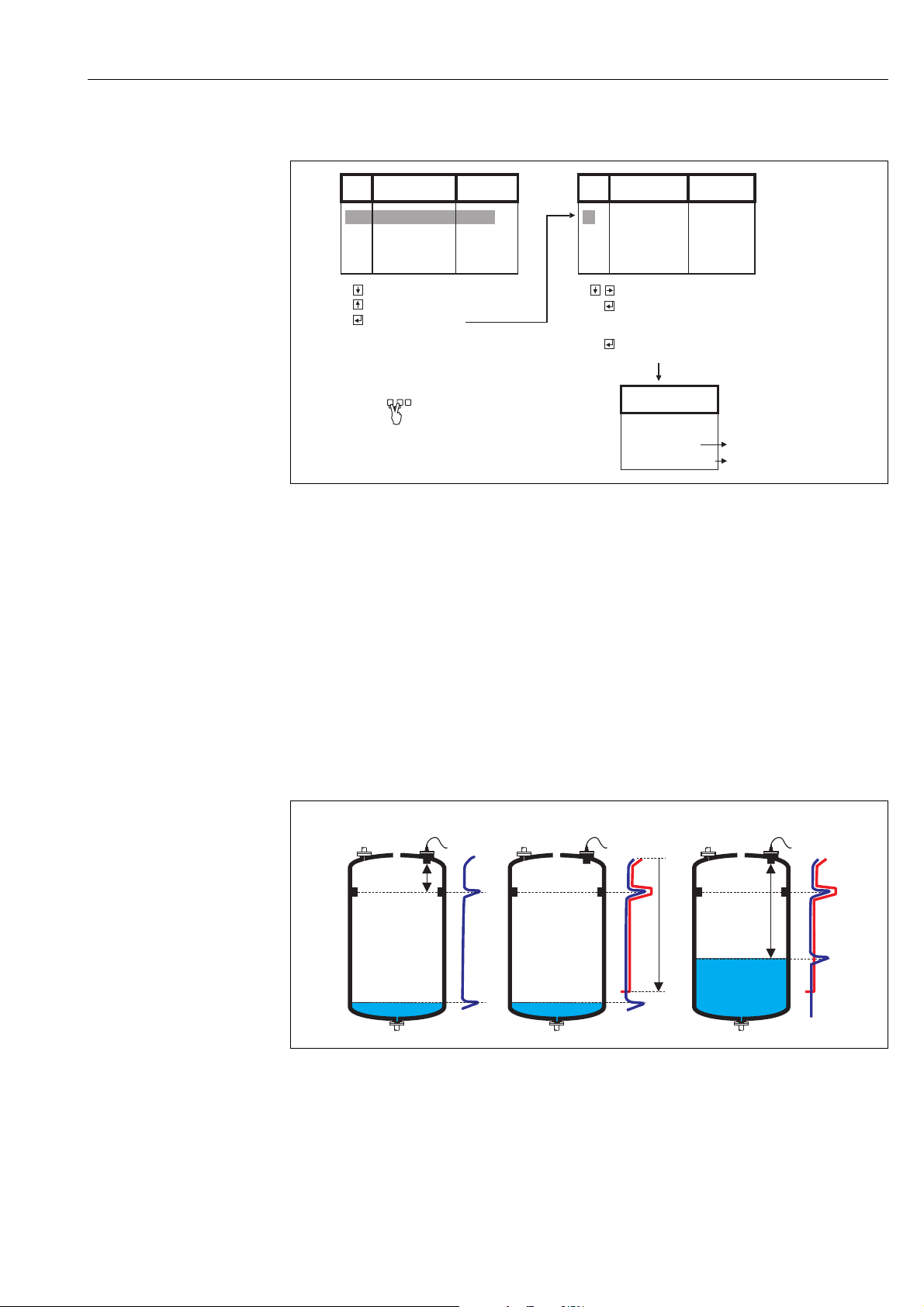
2.1.7 Interference echo suppression: Basic principles
The "check value" and "distance mapping" parameters are used to configure the interference
echo suppression of the Prosonic S.
The following picture shows the operating principle of the interference echo suppression:
A The envelope curve (a) contains the level echo and an interference echo. Without interference echo suppression,
the interference echo is evaluated.
B The interference echo suppression generates the mapping curve (b). This curve suppresses all echos within the
range of mapping (c).
C From now on, only those echos are evaluated, which are higher than the mapping curve. The interference echo is
below the mapping curve and is therefore ignored.
L00-FMU90xxx-19-00-00-yy-017
27
Page 28
The "level" menu
L100B
LVL1 dist. corr.
act. distance:D
D
display
D
display
=D
D
display
>D
D
display
<D
?
check distance:
!
Note!
In order to include all interference echos, the interference echo suppression should be performed
with the level as low as possible. If during commissioning the vessel can not be sufficiently emptied,
it is advisable to repeat the interference echo suppression at a later point of time (as soon as the level
reaches nearly 0%).
2.1.8 "LVL N check value" (N = 1 or 2)
LVL1 check value L100B
act. distance 1:
check distance:
L00-FMU90xxx-19-00-00-de-016
"actual distance N" (N = 1 or 2)
Displays the currently measured distance D
display
.
"check distance"
Use this parameter to state if the displayed distance D
matches the real distance D (measured
display
by a rule for example). Based on your selection, the Prosonic S automatically proposes a suitable
range of mapping.
You have got the following options:
• distance = ok
Choose this option if the displayed value D
matches the real distance D.
display
After selecting this option, the Prosonic S changes to the "LVL N distance mapping" parameter
set. The preset range of mapping is identical to D. That means: all interference echos above the
current product surface will be suppressed by the mapping curve.
• distance too small
Choose this option if the displayed value D
is smaller than the real distance D.
display
In this case the currently evaluated echo is an interference echo.
After selecting this option, the Prosonic S changes to the "LVL N distance mapping" parameter
set. The preset range of mapping is slightly larger than D
. Therefore, the currently evaluated
display
interference echo is suppressed by the mapping curve.
If after the mapping D
is still too small, repeat the mapping until D
display
matches the real
display
distance D.
• distance too big
Choose this option if the displayed value D
This error is not caused by interference echos. Therefore, no interference echo suppression is
exceeds the real distance D.
display
performed and the Prosonic S returns to the "level 1(2)" submenu. Check the calibration
parameters, especially the "empty calibration" and the "application parameters".
28
Page 29

The "level" menu
• distance unknown
Choose this option if you do not know the real distance D.
In this case, an interference echo suppression can not be performed and the Prosonic S returns to
the "level 1(2)" submenu.
• manual
Choose this option if you want to define the range of mapping manually.
The Prosonic S changes to the "LVL N distance mapping" function, where you can define the
required range of mapping.
2.1.9 "LVL N distance mapping" (N = 1 or 2)
LVL1 dist.map. L100B
act. distance 1:
range of mapping:
start mapping:
status:
"actual distance N" (N = 1 or 2)
Displays the currently measured distance between the reference point of the sensor and the product
surface. Compare this value to the real distance in order to find out if currently an interference echo
is evaluated.
"range of mapping"
Use this parameter to specify the range of the mapping curve. Normally, a suitable value has already
been entered automatically. Nevertheless, you can change this value if required.
"start mapping"
Select "yes" in this parameter in order to start the mapping. When the mapping is finished, the state
is automatically changed to "enable map".
The "LVL N state" parameter set appears, in which the currently mesaured level and distance are
displayed. Compare the displayed distance to the real distance in order to decide if a further mapping
is necessary.
If yes: Press the left-arrow key () in order to return to the "LVL N dist. map" parameter set.
If no: Press the right-arrow key (), in order to return to the "level (LVL) N" submenu.
"status"
Chap. 2.1.10, "LVL N State" parameter set
29
Page 30

The "level" menu
2.1.10 "LVL N state" (N = 1 or 2)
LVL1 state L100C
level 1:
act. distance 1:
status:
"level N" (N = 1 or 2)
Displays the currently measured level.
"act. distance N" (N = 1 or 2)
Dispalys the currently measured distance.
"status"
Use this parameter to define the status of the interference echo suppression.
• enable map
Choose this option in order activate the interference echo suppression. The mapping is then used
for signal evaluation.
• disable map
Choose this option in order to deactivate the interference echo suppression. The mapping is then
no longer used for signal evaluation but it can be reactivated if required.
• delete map
Choose this option in order to delete the mapping. It can not be reactivated again and the
instrument uses the preprogrammed default mapping.
30
Page 31

2.2 The "extended calibration" submenu
2.2.1 "LVL N distance mapping" (N = 1 or 2)
Is identical to the "LVL N distance mapping" parameter set in the "The "basic setup" submenu
ä 158", see above.
2.2.2 "LVL N check value" (N = 1 or 2)
LVL1 check value L1017
correction:
"correction"
This parameter can be used to shift the measured distance (between the reference point of the
sensor and the product surface) by a constant value. The distance entered into this parameter is
added to the measured distance.
The "level" menu
!
2.2.3 "LVL N correction" (N = 1 or 2)
LVL1 correction L1018
offset:
"offset"
This parameter can be used to shift the measured level by a constant value. The level entered into
this parameter is added to the measured level.
Note!
The level correction is applied before the linearisation.
2.2.4 "LVL N blocking distance" (N = 1 or 2)
LVL1 block. dist. L1019
blocking distance:
.
"blocking distance"
Indicates the blocking distance of the respective sensor.
31
Page 32

The "level" menu
t
20mA
100%
0/4mA
0%
(2)
(1)
(a)
(a)
(b)
(b)
2.2.5 "LVL N limitation" (N = 1 or 2)
LVL1 limitation L1019
limitation:
upper limit:
lower limit:
"limitation"
Use this parameter to specify if the measured value has a lower and/or upper limit.
Selection:
•off
• low limit
• high limit
• low/high limit
"upper limit"
Defines the upper limit for the measured value.
(only available for the options "high limit" and "low/high limit")
"lower limit"
Defines the lower limit for the measured value.
(only available for the options "low limit" and "low/high limit")
(1): lower limit; (2): upper limit
(a): limitation switched off; (b): limitation switched on
L00-FMU90xxx-19-00-00-yy-019
32
Page 33

2.2.6 "LVL N external input 1" "LVL N external input 2" (N = 1 or 2)
LVL1 ext. input1 L1020
input 1:
function:
The "level" menu
!
Note!
These parameters are only available for instruments with external limit switches
(FMU90-********B***).
These parameters are used to allocate up to 2 external limit switches to the level channel (e.g. one
minimum safety and one maximum safety switch). If one of these switches gives a signal, the level
assumes a specified value irrespective of the current echo signal.
"input N" (N = 1 or 2)
This parameter allocates an external limit switch to the level channel.
Selection:
• disabled (default)
no switch allocated
• ext. digin 1
external limit switch at the terminals 71, 72, 73
• ext. digin 2
external limit switch at the terminals 74, 75, 76
• ext. digin 3
external limit switch at the terminals 77, 78, 79
• ext. digin 4
external limit switch at the terminals 80, 81, 82
"function"
This parameter determines which value the level assumes if the limit switch sends a signal.
Selection:
• off (default)
no influence on the level value
• Min (0%)
If the limit switch sends a signal, a level value of 0% is generated.
• Max (100%)
If the limit switch sends a signal, a level value of 100% is generated.
• hold
If the limit switch sends a signal, the level is held on its current value.
• customer secific
If the limit switch sends a signal, the level assumes the value as defined by the customer in the
"value" parameter.
"value"
This parameter is only available for "function" = "customer specific".
It determines which value the level assumes if the limit switch sends a signal.
33
Page 34

The "level" menu
(1) (2)
0/4...20
mA
D
A
2.3 The "simulation" submenu
2.3.1 "LVL N simulation" (N = 1 or 2)
LVL1 Simulation L1022
simulation:
(sim. level value:)
(sim. vol. value:)
"simulation"
(1): simulation of level; (2): simulation of volume
The parameters of this set are used to simulate a level or a measured
value in order to check the linearisation, the signal output and the
connected switching units.
Use this parameter to select the simulation
mode:
• sim off.
This is the normal mode used for
measurement. No simulation is performed in
this mode.
• sim. level
After selection of this mode, the "sim. level
value" parameter appears, where you can
specify a level value (1). The display and the
output signal assume values according to this
level.
Use this mode to check the linearisation.
• sim. volume
After selection of this mode, the "siml vol.
value" parameter appears, where you can
L00-FMU90xxx-19-00-00-yy-020
specify a volume value (2). The output
assumes a value according to this volume.
Use this mode to check the signal output and
the connected switching units.
Note!
!
An error mesage is generated as long as one of
the modes "sim. level" or "sim. volume" is
active.
34
Page 35

The "level" menu
"sim. level value"
This parameter is available for a level simulation. It is used to specify the desired level value. The
display and the output signal assume values according to this level.
"sim. vol. value"
This parameter is available for a volume simulation (more general: a simulation of the linearized
value). It is used to specify the desired volume (or linearized value). The output signal assumes a
value according to this volume.
35
Page 36

The "flow" menu
main menu
flow
flow
flow
flow counter
flow
flow 1
flow 2
main menu
flow
flow
flow1+backwater
flow counter
flow1+backwater
flow
backwater
operating modes
“level+flow”
“flow”
operating mode
“flow+backwater”
3 The "flow" menu
The "flow" submenu is used for the calibration of
• flow measurements (1 or 2 channels)
• back water alarm
•flow counters
The structure of the submenu depends on the selected operating mode
6)
:
L00-FMU90xxx-19-00-00-en-076
!
Always start by calibrating the first flow channel ("flow 1" submenu).
Thereafter, you can calibrate the following as required:
• the second flow channel ("flow 2" submenu)
• the backwater detection ("backwater" submenu)
• the flow counters ("flow counter" submenu)
3.1 The "flow N" submenu (N = 1 or 2)
flow 1 F1002
basic setup
extended calibr.
simulation
Note!
The "flow 2" submenu is only available for instruments with 2 sensor inputs. It is identical to the
"flow 1 " submenu.
6) The operating mode is selected during the first setup. Nevertheless, it can be changed at any time if required ("device properties" menu, "operating params"
submenu, "operating mode" parameter set).
36
Page 37

3.1.1 The "basic setup" submenu
"flow N sensor selection" (N = 1 or 2)
flow1 sensor sel. F1003
input:
sensor selection:
detected:
"input"
Use this parameter to allocate a sensor to the channel.
Selection
• no sensor
•sensor 1
• sensor 2 (for instruments with 2 sensor inputs)
• average level
7)
The "flow" menu
!
"
"sensor selection"
Use this parameter to specify the type of the connected ultrasonic sensor.
Note!
• For the sensors FDU9x, the option "automatic" is recommended (default setting). With this
setting the Prosonic S recognizes the type of sensor automatically.
• For the sensors FDU8x, the type has to be assigned explicitly. The automatic sensor recognition
does not work for these sensors.
Caution!
After exchanging a sensor, observe the following:
The automatic sensor recognition is also active if a sensor has been exchanged
recognizes the type of the new sensor automatically and changes the "detected" parameter to fit the
new sensor. The measurement continues without break.
Nevertheless, in order to ensure perfect measurement, the following checks are required:
•Check the "empty calibration" parameter. Adjust this value if required. Take into account the
blocking distance of the new sensor.
•Go to the "flow N check value" parameter set and check the displayed distance. If required,
perform a new interference echo suppression.
"detected" (only available for "sensor selection" = "automatic")
Indicates the type of the automatically detected sensor.
"flow N linearization" (N = 1 or 2)
8)
. The Prosonic S
flow 1 linearizat F1004
type:
7) This option is only available if two level measurements have been calibrated. This is only possible for the "leve+flow" operating mode and a two channel instrument.
8) if the sensor is of the type FDU9x.
flow unit:
Note!
!
The selected linearization type determines which parameters are
present.
Only the parameters "type" and "flow unit" are always present.
37
Page 38

The "flow" menu
The "linearization" parameter set is used to calculate the flow from the measured level. The
Prosonic S provides the following linearization types:
• pre-programmed flow curves for commonly used flumes and weirs
• a freely editable linearization table (up to 32 points)
• a flow formula Q = C(h
Caution!
"
Flow measurement always requires a linearization.
"type"
Use this parameter to select the type of linearization.
Selection:
• none
No flow linearization is performed.
Note!
!
If this option has been selected, nor further parameters are available. A flow measurement is only
possible with one of the other options.
• flume/weir
In this type, the linearization is performed according to a preprogrammed linearization curve. The
type of curve is selected in the "curve" parameter. Additionally, the "flow unit" has to be
specified. The "max. flow" parameter displays the max. flow of the respective flume or weir. If
required, this value can be adjusted (as well as the "width" of the weir).
• table
In this type, a linearization table consisting of up to 32 pairs of values "level - flow" is used.
Additionally, the "flow unit" has to be specified. To enter and activate the table use the "edit"
and "status table" parameters.
• formula
In this type, the linearization is performed according to the formula
Q = C(h
The "alpha", "beta", "gamma" and "C" parameters appear, which are used to specify the
details of the curve. Additionally, the "flow unit" and the "max. flow" of the weir or flume
have to be specified.
+ h).
+ h) with freely selectable parameters
"flow unit"
Use this parameter to select the desired flow unit.
Caution!
"
After a change of the flow unit, the switching points of the limit relays have to be checked and
adjusted if required.
"curve"
This parameter is available for the "flume/weir" linearization type.
It is used to select the type of flume or weir. After the selection, a second list appears with differnt
sizes of the flume or weir
"linearization" function.
"width"
This parameter appears for the curves "rectangular weir", "NFX" and "trapezoidal weir". It is
used to specify the width of the respective weir.
"edit"
This parameter is used to enter or to view the linearization table. You have got the following options:
9) Tables of the flume and weir parameters can be found in the Appendix.
9)
. When you have confirmed your selection, the Prosonic S returns to the
38
Page 39

• read:
No.
Level
Value
1
0,0000
0,0000
2
0,0000
0,0000
3
0,0000
0,0000
…
0,0000
0,0000
: go to next row
: go to previous row
: open marked row
for editing
No.
Level
Value
1
0,0000
0,0000
2
0,0000
0,0000
3
0,0000
0,0000
…
0,0000
0,0000
: navigate within the table
: (for "Level" und "Value”)
open marked number
for editing
: (for "No.")
open row editor
Row function
(before current row)
Query: new position
Return to the previous
step by this
key combination.
- Delete row
- Insert row
- Move row
The table editor appears. An existing table can be viewed but not changed.
• manual:
The table editor appears. Table values can be entered and changed.
• delete:
The linearization table is deleted.
The table editor
The "flow" menu
"status"
Use this parameter to specify if the linearization table is to be used or not.
Selection:
• enabled
The table is used.
• disabled
The table is not used. A flow value is not calculated.
"alpha", "beta", "gamma" and "C"
These parameters are available for the "formula" linearization type.
They are used to specify the parameters of the flow formula:
Q = C(h
+ h)
"max flow"
This parameter is available for the linearization types "flume/weir" and "formula".
It is used to specify the maximum flow of the respective weir or flume.
For each of the preprogrammed curves, a default value is preset. However, this value can be
adjusted, e.g. if the weir/flume is applied for lower flows.
The maximum flow corresponds to an output current of 20 mA.
L00-FMU90xxx-19-00-00-de-006
39
Page 40

The "flow" menu
FDU 91
E
D
L
FDU 91
E
L
D
"flow N empty calibration" (N = 1 or 2)
flow 1 empty cal. F1010
empty E: 0,00 m
blocking dist.
"empty E"
Use this parameter to enter the empty distance E, i.e. the distance between the reference point of
the sensor and the zero point of the flume or weir.
For flumes, the zero point is the bottom of the flume at the narrowest position:
Example: Khafagi-Venturi flume
E: empty distance; D: measured distance; L: level
For weirs, the zero point is the lowest point of the weir crest:
Example: Triangular weir
E: empty distance; D: measured distance; L: level
L00-FMU90xxx-19-00-00-yy-027
L00-FMU90xxx-19-00-00-yy-028
40
Page 41

The "flow" menu
"blocking distance"
Indicates the blocking distance of the respective sensor. The blocking distance is measured from the
reference point of the sensor. The maximum level may not project into the blocking distance.
Type of sensor blocking distance (BD) maximum measuring distance
FDU90 0.07 (0.2) 3.0 (9.8) (for liquids)
FDU91/FDU91F 0.3 (1.0) 10 (33) (for liquids)
FDU92 0.4 (1.3) 20 (66) (for liquids)
FDU93 0.6 (2.0) 25 (82) (for liquids)
FDU95 - *1*** (low temperature version) 0.7 (2.3) 45 (148) (for solids)
FDU95 - *2*** (high temperature version) 0.9 (3.0) 45 (148) (for solids)
FDU96 1.6 (5.2) 70 (230) (for solids)
FDU80/FDU80F 0.3 (1.0) 5 (16) (for liquids)
FDU81/81F 0.5 (1.6) 10 (33) (for liquids)
FDU82 0.8 (2.6) 20 (66) (for liquids)
FDU83 1.0 (3.3) 25 (82) (for liquids)
FDU84 0.8 (2.6) 25 (82) (for solids)
FDU85 0.8 (2.6) 45 (148) (for solids)
FDU86 1.6 (5.2) 70 (230) (for solids)
m (ft)
1) valid for optimum process conditions
1)
"flow N" (N = 1 or 2)
flow 1 F1005
flow 1:
level:
sensor:
"flow N" (N = 1 or 2)
Displays the currently measured flow Q.
If the displayed value does not match the real flow, it is recommended to check the linearisation.
"level"
Displays the currently measured level L.
If the displayed value does not match the real level, it is recommended to check the empty
calibration.
"sensor"
Displays the currently measured distance D between the reference point of the sensor and the liquid
surface.
If the displayed value does not match the real distance, it is recommended to perform an
interference echo suppression.
41
Page 42

The "flow" menu
(a) (a)
(b)
(c)
(a)
(b)
A
B
C
D
display
=D
D
display
>D
D
display
<D
?
D
L0000
flow 1 check value
distance:D
display
check distance:
Interference echo suppressio: Basic principles
The "flow N check value" and "flow N mapping" parameter sets are used to configure the inter-
ference echo suppression of the Prosonic S.
The following picture shows the operating principle of the interference echo suppression:
L00-FMU90xxx-19-00-00-yy-030
A The envelope curve (a) contains the level echo and an interference echo. Without interference echo suppression,
the interference echo is evaluated.
B The interference echo suppression generates the mapping curve (b). This curve contains all echos which are
located within the range of mapping (c).
C From now on, only those echos are evaluated, which are higher than the mapping curve. The interference echo is
ignored because it is lower than the mapping curve.
!
Note!
In order to include all interference echos, the interference echo suppression should be performed
with the level as low as possible. If during the commissioning the channel can not be sufficiently
emptied, it is advisable to repeat the interference echo suppression at a later point of time (as soon
as the level reaches nearly 0%).
"flow N check value" (N = 1 or 2)
flow 1 check value F1006
distance:
check distance:
42
L00-FMU90xxx-19-00-00-de-031
Page 43

"distance"
The "flow" menu
Displays the currently measured distance D
"check distance"
Use this parameter to state if the displayed distance D
your selection, the Prosonic S automatically proposes a suitable range of mapping.
You have got the following options:
• distance = ok
Choose this option if the displayed value matches the real distance.
After selecting this option, the "flow N mapping" parameter set appears. The preset range of
mapping is equal to D. That means: all interference echos which are above the current product
surface will be mapped out in the interference echo suppression.
• distance too small
Choose this option if the displayed value is smaller than the real distance D.
In this case, the currently evaluated echo is an interference echo.
After selecting this option, the "flow N mapping" parameter set appears. The preset range of
mapping is slightly larger than D
be mapped out by the interference echo suppression.
• distance too big
Choose this option if the displayed value D
This error is not caused by interference echos. Therefore, no interference echo suppression is
performed and the Prosonic S returns to the "flow N" parameter set. Check the calibration
parameters, especially the "empty calibration".
• distance unknown
Choose this option if you do not know the real distance D.
In this case, an interference echo supression can not be performed and the Prosonic S returns to
the "flow N" parameter set.
• manual
Choose this option if you want to define the range of mapping manually.
The "flow N mapping" parameter set appears, where you can define the required range of
mapping.
. Therefore, the currently evaluated interference echo will
display
.
display
matches the real distance D. Based on
display
is larger than the real distance D.
display
"flow N mapping" (N = 1 or 2)
flow 1 mapping F1008
sensor:
range of mapping:
start mapping:
status:
"sensor"
Displays the currently measured distance between the reference point of the sensor and the water
surface. Compare this value to the real distance in order to find out if currently an interference echo
is evaluated.
"range of mapping"
Use this parameter to specify the range of the mapping curve. Normally, a suitable value has already
been entered automatically. Nevertheless, you can change this value if required.
"start mapping"
Select "yes" in this parameter in order to start the mapping. When the mapping is finished, the state
is automatically changed to "enable map".
43
Page 44

The "flow" menu
The "flow N state" parameter set appears, in which the currently measured level, distance and
flow are displayed. Compare the displayed distance to the real distance in order to decide if a further
mapping is necessary.
If yes: Press the left-arrow key () in order to return to the "flow N mapping" parameter set.
If no: Press the right key () in order to return to the "flow N" submenu.
"status"
see below ("flow N status")
"flow N state" (N = 1 or 2)"
LVL1 state L100C
level:
sensor:
flow N:
status:
"level"
Displays the currently measured level.
"sensor"
Dispalys the currently measured distance between the reference point of the sensor and the liquid
surface.
"flow N" (N = 1 or 2)
Displays the currently measured flow.
"status"
Use this parameter to define the status of the interference echo suppression.
• enable map
Choose this option in order activate the interference echo suppression. The mapping is then used
for signal evaluation.
• disable map
Choose this option in order to deactivate the interference echo suppression. The mapping is then
no longer used for signal evaluation but it can be reactivated if required.
• delete map
Choose this option in order to delete the mapping. It can not be reactivated again and the
instrument uses the preprogrammed default mapping.
44
Page 45

3.1.2 The "extended calibration" submenu
"flow N mapping" (N = 1 or 2)
flow 1 mapping F1010
sensor:
range of mapping:
start mapping:
status:
Is identical to the "flow N mapping" parameter set in the "The "basic setup" submenu", ä 18.
"flow N low cut off" (N = 1 or 2)
flow1 low cut off F1011
low flow cut off:
flow 1:
The "flow" menu
"low flow cut off"
Use this function to enter a lower limit for the flow (percentage of the "max flow", ä 39). If the
flow falls below this cut off limit, it is not taken into account for the flow counters (which are parametrized in the "flow counter" submenu, see below).
"flow N" (N = 1 or 2)
Displays the currently measured flow.
"flow N distance correction"
flow 1 dist. corr. F1012
correction:
flow1:
"correction"
This parameter can be used to shift the measured distance (from the reference point of the sensor
to the water surface) by a constant value. The distance entered into this parameter is added to the
measured distance.
"flow N" (N = 1 or 2)
Displays the currently measured flow in order to show the influence of the distance correction on
the flow.
45
Page 46

The "flow" menu
"flow N level correction" (N = 1 or 2)
flow 1 level corr. F1013
offset:
flow 1:
"offset"
This parameter can be used to shift the level by a constant value. The level entered into this parameter is added to the measured level.
"flow N" (N = 1 or 2)
Displays the currently measured flow in order to show the influence of the level correction on the
flow.
"flow N blocking distance" (N = 1 or 2)
flow 1 block. dist. F1015
blocking dist.:
"blocking distance"
Displays the blocking distance of the connected sensor.
"flow N limitation" (N = 1 or 2)
flow 1 limitation F1014
limitation:
upper limit:
lower limit:
"limitation"
Use this parameter to specify if the measured value has a lower and/or upper limit.
Selection:
•off
• low limit
• high limit
• low/high limit
46
"upper limit"
Defines the upper limit for the measured value.
(only available for the options "high limit" and "low/high limit")
Page 47

"lower limit"
t
20mA
100%
0/4mA
0%
(2)
(1)
(a)
(a)
(b)
(b)
Defines the lower limit for the measured value.
(only available for the options "low limit" and "low/high limit")
(1): lower limit; (2): upper limit
(a): limitation switched off; (b): limitation switched on
"flow N external input 1"
"flow N external input 2"
(N = 1 or 2)
The "flow" menu
L00-FMU90xxx-19-00-00-yy-019
!
flow1 ext. input1 L1020
input 1:
function:
Note!
These parameters are only available for instruments with external limit switches
(FMU90-********B***).
These parameters are used to allocate up to 2 external limit switches to the flow channel (e.g. one
minimum safety and one maximum safety switch). If one of these switches gives a signal, the flow
assumes a specified value irrespective of the current echo signal.
"input N" (N = 1 or 2)
This parameter allocates an external limit switch to the flow channel.
Selection:
• disabled (default)
no switch allocated
• ext. digin 1
external limit switch at the terminals 71, 72, 73
• ext. digin 2
external limit switch at the terminals 74, 75, 76
• ext. digin 3
external limit switch at the terminals 77, 78, 79
• ext. digin 4
external limit switch at the terminals 80, 81, 82
47
Page 48

The "flow" menu
(1) (2)
0/4...20
mA
D
A
"function"
This parameter determines which value the flow assumes if the limit switch sends a signal.
Selection:
• off (default)
no influence on the flow value
• Min (0%)
If the limit switch sends a signal, a flow value of 0% is generated.
• Max (100%)
If the limit switch sends a signal, the maximum flow value of the respective flume or weir is
generated.
• hold
If the limit switch sends a signal, the flow is held on its current value.
• customer secific
If the limit switch sends a signal, the flow assumes the value as defined by the customer in the
"value" parameter.
"value"
This parameter is only available for "function" = "customer specific".
It determines which value the flow assumes if the limit switch sends a signal.
3.1.3 The "simulation" submenu
"flow N simulation" (N = 1 or 2)
flow 1 simulation F1020
simulation:
(sim. level value:)
(sim. flow value:)
"simulation"
The parameters of this set are used to simulate a level or a flow in
order to check the linearisation, the signal output and the connected
switching units.
48
Use this parameter to select the simulation mode:
• sim. off
• sim. level
• flow
L00-FMU90xxx-19-00-00-yy-032
This is the normal mode used for measurement. No simulation is performed in this mode.
After selection of this mode, the "sim. level value" parameter appears, where you can specify a
level value (1). The display and the output signal assume values according to this level.
Use this mode to check the linearization.
Page 49

The "flow" menu
After selection of this mode, the "sim. flow value" parameter appears, where you can specify a
flow value (2). The output signal assumes a value according to this flow.
Use this mode to check the signal output and the connected switching units.
!
Note!
An error message is generated as long as one of the modes "sim. level" or "flow" is active.
"sim. level value"
This parameter is available for a level simulation. It is used ot specify the desired level value. The
display and the output signal assume values according to this level.
"sim. flow value"
This parameter is available for a flow simulation. It is used to specify the desired flow value. The
output signal assumes a value according to this flow.
49
Page 50

The "flow" menu
Prosonic S
(a)
(b)
Q
h
1
h
2
3.2 The "backwater" submenu
3.2.1 Basics
The flow measurement can be impaired by backwater on the downstream side or by dirt within the
flume. The backwater and dirt detection function can detect these errors and ensure that the
Prosonic S reacts appropriately.
Two sensors are required for backwater and dirt detection. The first sensor is mounted above the
upstream water, the second above the downstream water. The Prosonic S evaluates the ratio of the
downstream level h
Backwater detection
Backwater is detected if the ratio h
In this case, the flow is continuously reduced to 0. An alarm relay can be configured which indicates
the backwater alarm.
Dirt detection
Dirt within the flume is detected if the ratio h
alarm relay can be configured which indicates the dirt alarm.
and the upstream level h1.
2
exceeds a critical value (typically 0,8 for Venturi flumes).
2/h1
falls below a critical value (typically 0,1). An
2/h1
L00-FMU90xxx-19-00-00-yy-033
(a): Upstream sensor;(b): Downstream sensor
!
Note!
The ultrasonic sensor for the measurement of the downstream water level should be installed at a
sufficient distance from the discharge of the flume. The measuring point must be selected in such a
way that the surface of the water is calmed down and the level is not influenced by the flume
anymore.
3.2.2 The "basic setup" submenu
"backwater sensor selection"
backw. sensor sel. F1304
input:
sensor selection:
detected:
50
Page 51

!
"
The "flow" menu
"input"
Use this parameter to allocate the downstream sensor to the channel.
The available options depend on the instrument version and the connected sensors.
"sensor selection"
Use this parameter to specify the type of the connected ultrasonic sensor.
Note!
• For the sensors FDU9x, the option "automatic" is recommended (default setting). With this
setting the Prosonic S recognizes the type of sensor automatically.
• For the sensors FDU8x, the type has to be assigned explicitly. The automatic sensor recognition
does not work for these sensors.
Caution!
After exchanging a sensor, observe the following:
The automatic sensor recognition is also active if a sensor has been exchanged
recognizes the type of the new sensor automatically and changes the "detected" parameter to fit the
new sensor. The measurement continues without break.
Nevertheless, in order to ensure perfect measurement, the following checks are required:
•Check the "backwater empty calibration". Adjust this value if required. Take into account the
blocking distance of the new sensor.
•Go to the "backwater check value" parameter and check the displayed distance. If required,
perform a new interference echo suppression.
10)
. The Prosonic S
"detected" (only available for "sensor selection" = "automatic")
Indicates the type of the automatically detected sensor.
"backwater empty calibration"
backw. empty cal. F1305
empty E:
blocking dist.:
"empty E"
Use this parameter to enter the empty distance for the downstream sensor, ä 40.
"blocking distance"
Displays the blocking distance BD of the downstream sensor.
"backwater detection"
backw. detection F1305
ratio B:
10) if the sensor is of the type FDU9x.
51
Page 52

The "flow" menu
h2/h1 <B
h1
h2
h2/h1 >B
h1
h2
h2
h1
h2
h1
h2/h1 > D h2/h1 < D
"ratio B"
!
Use this parameter to specify the upper limit for the ratio h
2/h1
.
If during the measurement the ratio exceeds this limit, the backwater alarm becomes active, i.e.:
• the warning W 00 692 appears
• the backwater alarm relay is de-energized
11)
• if the backwater level continues to rise, the flow (indicated on the display and registered by the
counters) is continuously reduced to 0.
L00-FMU90xxx-19-00-00-yy-035
Note!
The default setting is B = 0,8.
This is the optimum value for Venturi flumes. To ensure reliable measurement it should not be
exceeded.
"dirt detection"
dirt detection F1306
ratio D:
"ratio D"
Use this parameter to specify the lower limit for the ratio h
If during the measurement the ratio falls below this level, the dirt alarm becomes active, i.e.
• the warning W 00 693 appears
• the dirt alarm relay is de-energized
12)
.
2/h1
.
L00-FMU90xxx-19-00-00-yy-036
11) In the "relay/controls" menu, one of the relays can be defined to be the backwater alarm relay.
12) In the "relay/controls" menu, one of the relays can be defined to be the dirt alarm relay
52
Page 53

"backwater"
D
display
=D
D
display
>D
D
display
<D
?
D
L0000
flow 1 check value
distance:D
display
check distance:
backwater F1307
act. backw. level:
act. flow level:
actual ratio:
flow 1:
The following is displayed in this parameter set:
• the current backwater level h
• the current flow level h
• the current ratio h
2/h1
(downstream level)
2
(upstream level)
1
• the current flow Q
Use these values to check the flow calibration as well as the calibration of the backwater and dirt
detection.
"backwater check value"
backw check value F1308
distance:
check distance:
The "flow" menu
"distance"
Displays the currently measured distance D
display
.
"check distance"
Use this parameter to state if the displayed distance D
matches the real distance D. Based on
display
your selection, the Prosonic S automatically proposes a suitable range of mapping.
You have got the following options:
• distance = ok
Choose this option if the displayed value matches the real distance.
After selecting this option, the "backwater mapping" parameter set appears. The preset range
of mapping is equal to D. That means: all interference echos which are above the current product
surface will be mapped out in the interference echo suppression.
• distance too small
Choose this option if the displayed value is smaller than the real distance D.
In this case, the currently evaluated echo is an interference echo.
L00-FMU90xxx-19-00-00-de-031
53
Page 54

The "flow" menu
After selecting this option, the "backwater mapping" parameter set appears. The preset range
of mapping is slightly larger than D
be mapped out by the interference echo suppression.
• distance too big
Choose this option if the displayed value D
This error is not caused by interference echos. Therefore, no interference echo suppression is
performed and the Prosonic S returns to the "backwater" parameter set. Check the calibration
parameters, especially the "empty calibration".
• distance unknown
Choose this option if you do not know the real distance D.
In this case, an interference echo supression can not be performed and the Prosonic S returns to
the "backwater" parameter set.
• manual
Choose this option if you want to define the range of mapping manually.
The "backwater mapping" parameter set appears, where you can define the required range of
mapping.
"backwater mapping"
backw. mapping F1309
sens. va. backw.:
range of mapping:
start mapping:
status:
. Therefore, the currently evaluated interference echo will
display
is larger than the real distance D.
display
"sensor value backwater"
Displays the currently measured distance between the reference point of the sensor and the water
surface. Compare this value to the real distance in order to find out if currently an interference echo
is evaluated.
"range of mapping"
Use this parameter to specify the range of the mapping curve. Normally, a suitable value has already
been entered automatically. Nevertheless, you can change this value if required.
"start mapping"
Select "yes" in this parameter in order to start the mapping. When the mapping is finished, the
status is automatically changed to "enable map".
The "backwater status" parameter set appears, in which the currently measured level, distance and
flow are displayed. Compare the displayed distance to the real distance in order to decide if a further
mapping is necessary.
If yes: Press the left-arrow key () in order to return to the "backwater mapping" parameter set.
If no: Press the right-arrow key () in order to return to the "backwater" submenu.
"status"
see below ("backwater status" parameter set).
54
Page 55

The "flow" menu
"backwater status"
backw. status F130A
act. backw. level:
distance:
flow 1:
status:
"actual backwater level"
Displays the currently measured level of the backwater sensor.
"distance"
Displays the currently measured distance between the backwater reference point of the sensor and
the liquid surface.
"flow 1"
Displays the currently measured flow.
"status"
Use this parameter to define the status of the interference echo suppression.
• enable map
Choose this option in order activate the interference echo suppression. The mapping is then used
for signal evaluation.
• disable map
Choose this option in order to deactivate the interference echo suppression. The mapping is then
no longer used for signal evaluation but it can be reactivated if required.
• delete map
Choose this option in order to delete the mapping. It can not be reactivated again and the
instrument uses the preprogrammed default mapping.
55
Page 56

The "flow" menu
3.2.3 The "extended calibration" submenu
"backwater mapping"
backw. status F1500
sens. val. backw.:
range of mapping:
start mapping:
status:
Is identical to the "backwater mapping" parameter set in the "basic setup" submenu, ä 18.
"backwater distance correction"
backw dist. corr. F1501
sensor offset:
"sensor offset"
This parameter can be used to shift the measured distance (from the reference point of the sensor
to the water surface) by a constant value. The distance entered into this parameter is added to the
measured distance.
"backwater correction"
backw. correction F1502
offset:
"offset"
This parameter can be used to shift the measured downwater level by a constant value. The level
entered into this parameter is added to the measured downwater level.
"backwater blocking distance"
backw. block.dist. F1504
blocking dist.:
56
"blocking distance"
Displays the blocking distance of the connected sensor.
Page 57

"backwater limitation"
t
20mA
100%
0/4mA
0%
(2)
(1)
(a)
(a)
(b)
(b)
backw limitation F1503
limitation:
upper limit:
lower limit:
"limitation"
Use this parameter to specify if the measured downstream level has a lower and/or upper limit.
Selection:
•off
• low limit
• high limit
• low/high limit
"upper limit"
Defines the upper limit for the downstream level.
(only available for the options "high limit" and "low/high limit")
The "flow" menu
"lower limit"
Defines the lower limit for the downstream level.
(only available for the options "low limit" and "low/high limit")
(1): lower limit; (2): upper limit
(a): limitation switched off; (b): limitation switched on
L00-FMU90xxx-19-00-00-yy-019
57
Page 58

The "flow" menu
"backwater external input 1"
"backwater external input 2"
backw.ext. input1 L1020
input 1:
function:
!
Note!
These parameters are only available for instruments with external limit switches
(FMU90-********B***).
These parameters are used to allocate up to 2 external limit switches to the backwater channel (e.g.
one minimum safety and one maximum safety switch). If one of these switches gives a signal, the
backwater level assumes a specified value irrespective of the current echo signal.
"input N" (N = 1 or 2)
This parameter allocates an external limit switch to the backwater channel.
Selection:
• disabled (default)
no switch allocated
• ext. digin 1
external limit switch at the terminals 71, 72, 73
• ext. digin 2
external limit switch at the terminals 74, 75, 76
• ext. digin 3
external limit switch at the terminals 77, 78, 79
• ext. digin 4
external limit switch at the terminals 80, 81, 82
"function"
This parameter determines which value the backwater level assumes if the limit switch sends a
signal.
Selection:
• off (default)
no influence on the backwater level
• Min (0%)
If the limit switch sends a signal, a backwater level value of 0% is generated.
• Max (100%)
If the limit switch sends a signal, the maximum backwater level is generated.
• hold
If the limit switch sends a signal, the backwater level is held on its current value.
• customer secific
If the limit switch sends a signal, the backwater level assumes the value as defined by the
customer in the "value" parameter.
"value"
This parameter is only available for "function" = "customer specific".
It determines which value the backwater level assumes if the limit switch sends a signal.
58
Page 59

3.2.4 The "simulation" submenu
"backwater simulation"
The "flow" menu
!
backw simulation F1600
simulation:
(sim. level value:)
"simulation"
Use this parameter to select the simulation mode:
• sim. off
This is the normal mode used for measurement. No simulation is performed in this mode.
• sim. level
After selection of this mode, the "sim. level value" parameter appears, where you can specify a
level value. The backwater and dirt detection generate a ratio h
Note!
An error message is generated as long as the "sim. level" mode is active.
"sim. level value"
This parameter is available for a level simulation. It is used ot specify the desired level value.
The parameters of this set are used to simulate a downstream water
level in order to check the parametrisation of the backwater and dirt
detection.
according to this level.
2/h1
59
Page 60

The "flow" menu
3.3 The "flow counter" submenu
flow counter F1100
totaliser
daily counter
In this submenu, select which type of counter you are going to parametrize.
Selection:
• totaliser (not resettable)
• daily counter (resettable)
A selection of up to three totalisers or daily counters appears
you are going to parametrize.
totaliser FX201
totaliser 1
totaliser 2
totaliser 3
13)
. Select the totaliser or daily counter
daily counter FX101
daily conter 1
daily conter 2
daily conter 3
13) The number of totalisers and daily conters depends on the instrument version and the installation environment.
60
Page 61

3.3.1 "totalizer N/daily counter N"
(N = 1 -3)
totalizer 1 F1202
allocation:
counting unit:
"allocation"
Use this parameter to allocate a flow to the counter.
Selection:
• none (default)
•flow 1, Q1
• flow 2, Q2 (for 2-channel instruments only)
• average flow, (Q1 + Q2)/2, (for 2-channel instruments only)
• flow 1-2, Q1 - Q2, (for 2-channel instruments only)
• flow 2-1, Q2 - Q1, (for 2-channel instruments only)
• flow 1+2, Q1 + Q2, (for 2-channel instruments only)
The "flow" menu
"counting unit"
Use this parameter to select the unit for the flow volume.
Selection:
3
•m
•l
•hl
•igal
•usgal
•barrels
3
•inch
3
•ft
•USmgal
•Ml
61
Page 62

The "flow" menu
3.3.2 "totalizer N/daily counter N" (N = 1 - 3)
totalizer 1 F1203
value:
overflow:
"value"
Displays the current flow volume.
"overflow"
Whenever the counter passes the overflow, this parameter is incremented by 1. The total flow
volume thus is:
V
= overflow x 107 + value
total
!
Note!
The totalizer value can also be displayed on the measured value screen (menu: "display",
parameters: "value 1" ... "value 6", ä 149)
In order to display the total value of the totalizer (value and overflow), select the "1 value +
bargraph" or "value max. size" option in the "type" parameter ( ä 148).
"reset" (only for the daily counters)
Use this parameter to reset the counter to "0".
Selection:
• no (default)
"value" and "overflow" retain their values.
• yes
"value" und "overflow" are reset to "0".
62
Page 63

3.3.3 "totalizer N/daily counter N" (N = 1 - 3)
totalizer 1 F1204
error handling:
"error handling"
Use this parameter to define the reaction of the Prosonic S in the case of an error.
Selection:
• stop
The Prosonic S stops counting.
• hold
The Prosonic S continues counting. It uses the flow value which was present at the moment the
error occured.
• actual value
The Prosonic S continues counting. It uses the current flow value (although its reliability is no
longer ensured).
The "flow" menu
63
Page 64

The "flow" menu
3.3.4 "daily counter N" (N = 1 - 3)
daily counter 1 F1105
external reset:
externl start:
"external reset"
This parameter allocates one of the digital outputs (DO) or for instruments with additional digital
inputs (FMU90-********B**) one of the external switch inputs (digin) to the counter.
Selection:
• disabled
• ext. digin 1
• ...
• ext. digin 4
• fieldbus DO1
• ...
• fieldbus DO10
"external start"
This parameter allocates one of the digital outputs (DO) or for instruments with additional digital
inputs (FMU90-********B**) one of the external switch inputs (digin) to the counter by which it
can be started.
Selection:
• disabled
• ext. digin 1
• ...
• ext. digin 4
• fieldbus DO1
• ...
• fieldbus DO10
64
Page 65

4 The "safety settings" menu
t
t
t
[mA]
[mA]
[mA]
22
22
22
3.6
3.6
3.6
t
[mA]
22
3.6
A
B
D
C
E
main menu CX001
safety settings
relay/controls
output/calculat
device properties
4.1 "output on alarm" (only for HART instruments)
output on alarm AX101
output 1:
output value 1:
output 2:
output value 2:
The "safety settings" menu
4.1.1 "output N" (N = 1 or 2) (only for HART instruments)
Defines the output current in the case of an alarm.
Selection:
• min (3.6 mA)
• max (22 mA) (Default)
• user specific (as defined in the "output value N" parameter)
• hold (the last value is held)
A: min.; B: max.; C: user specific; D: hold; E: output value
4.1.2 "oputput value N" (N = 1 or 2) (only for HART instruments)
Defines the output current in the case of an alarm.
L00-FMU90xxx-19-00-00-yy-069
(only available for "output N" = "user specific")
• range of values: 3.6 ... 22 mA
65
Page 66

The "safety settings" menu
t
min
[mA]
3.6
22
A
B
C
4.2 "output echo loss"
outp. echo loss AX102
level 1:
level 2:
!
Note!
The parameter set "output echo loss" (AX102) is valid only for level measurements. For flow
measurements there is an additional parameter set with a different code: "output echo loss"
(AX112).
The parameters of both sets are described in this section.
4.2.1 "level N" or "flow N" (N = 1 or 2)
Defines the output value in the case of an echo loss.
Selection:
• hold (Default)
The current value is held.
• ramp %/min
After the time defined in "delay echo loss" (see below), the output value is continuously shifted
towards 0% (for a negative ramp) or towards 100% (for a positive ramp). The ramp must be
specified as a percentage of the measuring range per minute ("ramp level N" parameter).
Note!
!
This option is not available for flow measurements.
L00-FMU90xxx-19-00-00-yy-070
A: delay echo loss; B: ramp (positive); C: ramp (negative)
• customer specific
After the time defined in "delay echo loss" (see below), the output assumes the value which has
been defined in the "value level N" or "value flow N" parameter.
66
• alarm
After the time defined in "delay echo loss" (see below), the instrument generates an alarm. The
output assumes the value defined in "output on alarm" (see above).
4.2.2 "ramp level N" (N = 1 or 2)
(only available for the option "ramp %/min")
Use this parameter to specify the ramp (percentage of the measuring range per minute).
Page 67

The "safety settings" menu
(BD)
A
4.2.3 "value level N" or "value flow N" (N = 1 or 2)
(only available for the option "customer specific")
Use this parameter to specify the output value in the case of an echo loss.
4.3 "delay echo loss"
delay echo loss AX103
delay sensor 1:
delay sensor 2:
4.3.1 "delay sensor N" (N = 1 or 2)
Use this parameter to define the delay time for echo loss.
After an echo loss, the instrument waits for the time specified in this parameter before generating
an alarm. Thus the measurement is not interrupted by short-time interferences.
4.4 "safety distance"
safety distance AX104
saf.dist. sen 1:
saf.dist. sen 2:
4.4.1 "safety distance sensor N" (N = 1 or 2)
Use this parameter to specify a safety distance
for the sensor.
The safety distance is located immediately
below the blocking distance. If the level projects
into the safety distance, an alarm is generated.
•Default: 0m
L00-FMU90xxx-19-00-00-yy-071
BD: blocking distance (depending on the type of sensor);
A: safety distance
67
Page 68

The "safety settings" menu
–
+
E
FMU90
1
BD
SD
Application example
The safety distance can be used to detect
flooding if a FDU90 sensor with flooding
protection tube is applied. In this case the safety
distance must be chosen in a way that it ends
slightly below the lower edge of the flooding
protection tube:
SD = min. 4 cm (1.6 in)
In order to indicate the flooding, a diagnostic
relay can be parametrized with the allocation
"safety distance channel 1/2" ( ä 78).
L00-FDU90xxx-05-00-00-xx-001
1: A detected flooding can generate an alarm and can be
indicated via a relay
BD: Blocking distance = 7 cm (2.8 in)
SD: safety distance to be defined: 4 cm (1.6 in)
4.5 "in safety distance"
in safety dist. AX105
in saf. dist. s 1:
in saf. dist. s 2:
4.5.1 "in safety distance sensor N" (N = 1 or 2)
Defines the reaction of the instrument if the level is in the safety distance.
Selection:
• warning (default)
A warning (A01651 or A02651) is generated but the instrument continues to measure.
If the level drops out of the safety distance, the warning disappears.
• alarm
The instrument enters the defined alarm state ("output on alarm"). Additionally, an error message
(A01651 or A02651) is generated. If the level drops out of the safety distance, the alarm
disappears and the instrument continues to measure.
• self holding
The instrument enters the defined alarm state ("output on alarm"). Additionally, an error message
(A01651 or A02651) is generated.
If the level drops out of the safety distance, the alarm remains active. The measurement is
continued only after a reset of the self holding.
68
Page 69

A: alarm; B: warning; C: self holding
t
[mA]
22
110%
SD
E01651
E02651
3.6 -10%
t
[mA]
22
SD
110%
3.6 -10%
t
[mA]
22
110%
RESET
3.6
-10%
E01651
E02651
E01651
E02651
A
B
C
4.5.2 "reset sensor N" (N = 1 or 2)
The "safety settings" menu
L00-FMU90xxx-19-00-00-yy-072
(only available for the option "self holding")
This parameter is used to reset the alarm in the case of a self holding.
Selection:
• no (default)
The alarm is not reset.
• yes
The alarm is reset. The measurement is resumed.
4.6 "reaction high temperature"
react. high temp AX107
overtemp sen 1:
max. temp. Sen. 1:
overtemp sen 2:
max. temp. Sen. 2:
4.6.1 "overtemperature sensor N" (N = 1 or 2)
Defines how the instrument reacts if the maximum temperature of the sensor is exceeded.
Selection:
• warning (default)
If the maximum temperature is exceeded, an error message (A01661 or A02661) is generated
but the measurement is continued.
• alarm
If the maximum sensor temperture is exceeded, the output assumes a defined value ("output on
alarm", see above). Additionally an error meassage (A01661 or A02661) is generated.
4.6.2 "maximum temperature sensor N" (N = 1 or 2)
Displays the maximum temperature of the respective sensor.
69
Page 70

The "safety settings" menu
4.7 "defective temperature sensor"
def. temp. sensor AX018
def. temp. sens 1
def. temp. sens 2
4.7.1 "defective temperature sensor N" (N = 1 or 2)
Defines how the instrument reacts in the case of a defective temperature sensor.
Selection:
• warning
If the temperature sensor is defective, an error message (A01661 or A02 661) is generated but the
measurement is continued.
• alarm (default)
If the temperature sensor is defective, the output assumes a defined value ("output on alarm", see
above). Additionally an error meassage (A01661 or A02661) is generated.
4.8 "relay delay"
relay delay AX109
startdelay relay:
4.8.1 "startdelay relay"
Use this function to define a start delay for the relays of the Prosonic S. When the supply voltage is
switched on, the relays do not switch immediately but one after another with the specified delay
time in between. This helps to avoid overloads of the power supply system.
•Default: 1s
70
Page 71

!
The "relays/controls" menu
5 The "relays/controls" menu
5.1 The "relay configuration" submenu
5.1.1 "relay allocation"
relay allocation RX101
relay 1
relay 2
relay 3
relay 4
Use this parameter to select the relay you are going to configure.
Selection:
• All relays of the instrument version at hand
Note!
If a function has already been allocated to one of the relays, the name of this function is displayed
next to the relay number.
5.1.2 "relay 1...6" (relay function)
relay 2 R2103
function:
After selecting a relay, the "relay N" (N = 1 ... 6) parameter set appears, which is used to configure
the relay.
To configure the relay, proceed according to the following steps:
1. Select the "function" parameter. The "select function" screen appears.
2. Select one of the following functions:
a. limit
After selecting this option, a further selection list appears. Select the measuring value to
which the limit relay is to be allocated.
Continue by sections Chap. 5.1.3 and Chap. 5.1.11.
b. time pulse (only for flow measurements)
(outputs a short pulses at regular time intervals)
After selecting this option, a further selection list appears. Select the option "time pulse".
Continue by sections Chap. 5.1.4 and Chap. 5.1.11.
c. counting pulse (only for flow measurements)
(outputs a short pulse after a defined flow volume)
After selecting this option, a further selection list appears. Select the measuring value to
which the pulses refer.
Continue by sections Chap. 5.1.5, Chap. 5.1.6 and Chap. 5.1.11.
d. alarm/diagnostics
71
Page 72

The "relays/controls" menu
After selecting this option, a further selection list appears. Select the alarm to which the
relay is allocated.
Selection:
– alarm relay
the relay is energized if an "alarm" type error is detected.
Continue by sections Chap. 5.1.7 and Chap. 5.1.11.
– diagnostics
a specific state of the instrument (e.g. loss of echo) can be allocated to the relay. The relay
becomes energized as soon as this state occurs.
Continue by sections Chap. 5.1.8 and Chap. 5.1.11.
– backwater alarm
The relay is energized if a backwater alarm is active.
This option is only available if the operating mode is "flow+backwater"
Continue by sections Chap. 5.1.9 and Chap. 5.1.11.
– dirt alarm
The relay is energized if a dirt alarm is active.
This option is only available if the operating mode is "flow+backwater"
Continue by sections Chap. 5.1.10 and Chap. 5.1.11.
e. fieldbus (DO relay)
After selecting this option, a further selection list appears. Select the DO block to which the
relay is to be connected.
No additional parametrization is required.
f. none
The relay is not used.
3. Now, the instrument switches back to the "relay N" (N= 1 ... 6) parameter set. Depending
on your selections, further parameters are now available which you can use to complete the
configuration. Details are described in the following sections.
15)
(for PROFIBUS DP instruments only)
14)
.
.
5.1.3 "relay N" (N = 1 - 6)
(Parametrization of a limit relay)
relay 2 R2103
function: limit
limit type:
switch on point:
switch off point:
"Limit type"
Use this parameter to define the type of limit.
Selection:
• standard
For this limit type, a switch on point and a switch off point have to be defined. The switching
behaviour depends on the relative position of these switching points.
a. switch on point > switch off point
The relay is energized if the measured value rises above the switch on point.
The relay is de-energized if the measured value falls below the switch off point.
b. switch on point < switch off point
The relay is energized if the measured value falls below the switch on point.
The relay is de-energized if the measured value rises above the switch off point.
14) The operating mode is set during the first setup of the instrument. It can be changed by "device properties/operating parameters/operating mode".
15) A fieldbus relay (DO relay) switches according to a binary value (e.g. from a SPS) which is connected to the DO block of the instrument.
72
Page 73

The "relays/controls" menu
m, ft, m /h, ft /s, °C, m/min, ft/min, …
33
t
t
A
B
C
D
t
t
B
A
C
D
m, ft, m /h, ft /s, °C, m/min, ft/min, …
33
L00-FMU90xxx-19-00-00-yy-061
A: switch on point; B: switch off point; C: relay energized; D: relay de-energized
• tendency/speed
This limit type is similar to the "standard" type. The only difference is that variations with time of
the measured value are examined instead of the measured value itself. Therefore, the unit for the
switching points is "measuring value unit per minute".
• inband
For this limit type, an upper and a lower switching point have to be defined.
The relay is energized if the measured value is between the two switching points.
The relay is de-energized if the measured value is above the upper or below the lower switching
point.
Additionally, a hysteresis can be defined, which affects both switching points.
• out of band
For this limit type, an upper and a lower switching point have to be defined.
The relay is energized if the measured value is above the upper or below the lower switching
point.
The relay is de-energized if the measured value is between the two switching points.
Additionally, a hysteresis can be defined, which affects both switching points.
73
Page 74

The "relays/controls" menu
m, ft, m /h, ft /s, °C, m/min, ft/min, …
33
t
t
A
B
C
D
E
E
m, ft, m /h, ft /s, °C, m/min, ft/min, …
33
t
t
A
B
C
D
E
E
1
2
"
"
L00-FMU90xxx-19-00-hfsdjhfjkdfkfhk f00-yy-062
1: "inband" limit relay; 2: "out of band" limit relay
A: upper switching point; B: lower switching point; C: relay energized; D: relay de-energized; E: hysteresis
"switch on point" and "switch off point"
(for the "standard" limit type)
Define the switching points in these parameters.
They have the same unit as the measured value.
Caution!
After a change of the "unit level" or "flow unit" the switching points have to be checked and adjusted
if required.
"switch on /min" and "switch off /min"
(for the "tendency/speed" limit type)
Define the switching points in these parameters.
Their unit is the measured value unit per minute.
Caution!
After a change of the "unit level" or "flow unit" the switching points have to be checked and adjusted
if required.
"upper switching point" and "lower switching point"
(for the "inband" and "out of band" limit types)
74
Define the switching points in these parameters.
They have the same unit as the measured value.
Caution!
"
After a change of the "unit level" or "flow unit" the switching points have to be checked and adjusted
if required.
"hysteresis"
(for the "inband" and "out of band" limit types)
Define the hysteresis in this parameter. It has the same unit as the measured value.
The hysteresis affects the upper and the lower swtiching point.
Page 75

5.1.4 relay N (N = 1 - 6)
t
C
D
A
B
(Parametrization of a time pulse relay)
(only for instrument versions with flow functionality:
FMU90 - *2********** and FMU90 - *4**********)
relay 2 R2103
function: time pulse
pulse width:
pulse time:
"pulse width" and "pulse time"
Use these parameters to specify the time interval
between two pulses (pulse time) and the
duration of each pulse (pulse width).
pulse time
•unit: min
•default: 1 min
• range of values: 1 to 65000 min
pulse width
•unit: ms
• default: 200 ms
• range of values: 200 to 60000 ms
The "relays/controls" menu
L00-FMU90xxx-19-00-00-yy-063
A: pulse time; B: pulse width;
C: relay energized; D: relay de-energized
5.1.5 "relay N" (N = 1 - 6)
(Parametrization of a counting pulse relay)
relay 2 R2103
function: pulse flow 1
counter unit:
pulse value:
pulse width:
"counter unit"
Use this parameter to select the unit for the flow volume.
Selection:
•l (default)
•hl
•Ml
3
•m
3
•dm
3
•cm
3
•ft
3
•inch
•us gal
•us mgal
•i gal
•barrels
75
Page 76

The "relays/controls" menu
"pulse value"
!
Use this parameter to specify the flow volume after which a pulse is generated.
Default: 100 m
"pulse width"
Use this parameter to specify the width of each pulse.
Default:
• HART: 200 ms
• PROFIBUS DP: 1000 ms
Range of values:
• 200 to 60000 ms
Note!
If a relay is used in a PROFIBUS DP instrument to transmit the pulses, the pulse width can be
reduced. If the DI block is used, 1000 ms is the smallest possible value.
3
5.1.6 "relay N " (N = 1 - 6) (Display of the counting value)
relay 2 R2105
pulse counter:
overflow x 10
reset counter:
start counter:
7
:
!
"pulse counter"
Displays the number of pulses which have been generated since the last overflow.
"overflow"
Displays, how many times the pulse counter has already passed the overflow.
Note!
The total flow volume is:
V
= (overflow x 107+ pulse counter) x pulse value
total
"reset counter"
Use this parameter to reset the counter.
Selection:
• no (default)
"pulse counter" and "overflow" retain their values.
• yes
"pulse counter" and "overflow" are reset to "0".
76
Page 77

The "relays/controls" menu
t
123 4 56789
t
m /h, ft /s, …
33
A
B
C
D
m,ft,…
33
E
F
t
100%
t
A
B
C
D
0%
L00-FMU90xxx-19-00-00-yy-064
A: flow; B: pulse width; C: relay energized; D: relay de-energized; E: pulse value; F: pulse counter
"start counter" and "stop counter"
You can use these parameters to exclude very small and very large flows from being counted.
If the flow is below "start counter" or above "stop counter" no pulses are generated. Both values are
to be specified as a percentage of the maximum flow (Q
max
).
• Default of "start counter": 0%
• Default of "stop counter": 100%
L00-FMU90xxx-19-00-00-yy-065
A: start counter; B: stop counter; C: relay energized; D: relay de-energized
77
Page 78

The "relays/controls" menu
5.1.7 "relay N" (N = 1 ...6) (Parametrization of an alarm relay)
relay 2 R2103
function: alarm
For an alarm relay, no additional parameters are required. Press "" in order to proceed to the next
parameter set.
5.1.8 "relay N" (N = 1 - 6) (Parametrization of a diagnostic relay)
relay 2 R2103
function: diagnostics
allocation 1:
allocation 2:
"allocation 1/2"
A specific instrument state or event can be allocated to each of these parameters. The relay is deenergized as soon as one of these states or events occurs.
Selection:
• echoloss sensor 1/2/1+2
• defective temperature sensor1/2
• defective external temperature sensor
• Accumulated alarm: defective temperature sensor
•overtemp. sensor 1/2
• Accumulated Alarm: overtemp.
• safety distance channel 1/2
• Accumulated Alarm: safety distance
5.1.9 "relay N" (N = 1 ...6) (Parametrization of a backwater alarm relay)
relay 2 R2103
function: backwat. alarm
78
For a backwater alarm relay, no additional parameters are required. Press "" in order to proceed
to the next parameter set.
Page 79

The "relays/controls" menu
5.1.10 "relay N" (N = 1 ...6) (Parametrization of a dirt alarm relay)
relay 2 R2103
function: dirt alarm
For a dirt alarm relay, no additional parameters are required. Press "" in order to proceed to the
next parameter set.
5.1.11 "relay N (N = 1 - 6)" (Relay behavior)
relay X RX104
switch delay:
invert:
error handling:
"switch delay" (only available for limit relays)
Use this parameter to specify the switch delay (in seconds).
The relay does not switch immediately after the switch-on point has been exceeded but only after
the specified delay.
The measured value must exceed the switch-on point during the entire delay time.
"invert"
Use this parameter to specify if the switching direction of the relay is to be inverted.
Selection:
• no (default)
The switching direction of the relay is not inverted. The relay switches as described in the above
sections.
• yes
The switching direction of the relay is inverted. The states "energized" and "de-energized" are
interchanged.
"error handling" (not available for alarm and diagnostic relays)
Use this parameter to specify the reaction of the relay in the case of an error.
Selection:
• actual value
The relay switches according the the currently measured value (although its reliability is not
ensured).
• hold (default)
– Limit relay: The current switching state of the relay is maintained.
– Counting pulse relay: The counter uses the flow value which was present when the error
occurred.
• switch on
(only available for limit relays)
The relay is energized.
• switch off
79
Page 80

The "relays/controls" menu
L
A
B
t
t
C
D
(only available for limit relays)
The relay is de-energized.
• stop
(only available for counting pulse and time pulse relays)
No pulses are generated as long as the error is present.
5.2 The "pump control N" submenu - standard
(N = 1 or 2)
!
!
Note!
Depending on the order code of the instrument, different functionalities can be configured for the
pump control. The order code of the instrument can be found on the nameplate and in the operating
menu at "system information/device information".
This chapter is only valid for instruments with standard pump control
(FMU90-*1********** and FMU90-*2**********).
For the enhanced pump control see chapter 5.3
(FMU90-*3********** and FMU90-*4**********).
Note!
The "pump control N" submenus are only present if "pump control" has been selected in "device
properties/operating parameters/controls".
5.2.1 Basic principles
Switch points
The pump control is used to start or stop pumps depending on the measured level. To do this, a
switch-on point and a switch-off point is defined for each pump. Additionally, a relay is assigned to
the pump and the switching is performed by this relay.
Two cases can be distinguished for the swichting behaviour of this relay:
a. Switch-on point > Switch-off point
The pump is switched on if the level rises above the switch-on point (A). It is switched off if
the level drops below the switch-off point (B).
Example: Emptying of a flood control reservoir.
80
A: switch-on point; B: switch-off point; C: pump on; D: pump off
b. Switch-on point < Switch-off point
The pump is switched on if the level drops below the switch-on point (A). It is switched off if
the level rises above the switch-off point (B).
L00-FMU90xxx-19-00-00-yy-051
Page 81

Example: Filling of a storage vessel
L
A
B
t
t
C
D
A: switch-on point; B: switch-off point; C: pump on; D: pump off
Operating mode
The "relays/controls" menu
L00-FMU90xxx-19-00-00-yy-052
The Prosonic S can control several pumps simultaneously - depending on the number of relays (s.
feature 70 of the product structure). If two or more pumps are applied for one level channel, you
can choose between two different operating modes:
a. Non-alternating pump control
In this mode, each pump is switched according to the switching points allocated to it.
b. Alternating pump control
In this mode, the switching points are not allocated to the individual pumps. Instead, the relays
are switched in a way that ensures uniform usage of all pumps. This is achieved by the
following rules:
1. If the level rises above one of the switch-on points, that relay switches on, which at that
moment has been switched off the longest time. This is not necessarily the relay to which
the switch-on point belongs.
2. If the level drops below one of the switch-off points, that relay switches off, which at that
moment has been switched on the longest time. This is not necessarily the relay to which
the switch-off point belongs.
However, there are two restrictions to these rules:
3. Rising of the level above a switch-on point effects switching on of a relay only if the
corresponding switch-off point has been reached before.
4. Dropping of the level below a switch-off points effects switching-off of a relay only if the
corresponding switch-on point has been reached before.
Note!
!
If two pumps in the same range are to operate alternately, their switch-on and switch-off points
are identical. This switching response can be achieved by assigning switch points to the second
relay which can never be reached.
Example
In the switching range between 60% and 40%, two pumps should be operated alternately, i.e.
when pump 1 in running, pump 2 is switched off and vice versa. These relays are programmed
as follows:
– Relay 1: switch-on point: 60%; switch-off point: 40%
– Relay 2: switch-on point: e.g. 160%; switch-off point: e.g. 120%.
81
Page 82

The "relays/controls" menu
P1
P1
P1
P2
P2
P3
P3
P2
P3
t
L
P1 P2 P3
A
A B
A B
B
C
C
C
C
C
C
D
D
D
D
D
1
2
D
1: Alternating pump control; that pump is switched on (switched off), which has been switched off (switched on) the
longest time.
2: Non-alternating pump control; each switching point is allocated to a different pump.
A: switch-on point of the pump; B: switch-off point of the pump; C: pump on; D: pump off;
L00-FMU90xxx-19-00-00-yy-053
Limit control versus pump rate control
If several pumps are connected, you can choose between limit control (as described above) and
pump rate control.
Limit control
If limit control has been selected, the relays are switched according to the swichting points as
described above.
Pump rate control
If pump rate control has been selected, there is only one switch-on point and one switch-off point,
which are valid for all relays. Additionally, a desired pump rate has to be specified.
If the level rises above (or falls below) the switch-on point, initially only one pump is switched on.
If the desired pump rate has not been achieved after the selected hook-up interval, an additional
pump is switched on. Similarly, further pumps are switched on in intervals until the desired pump
rate has been achieved.
82
Page 83

The "relays/controls" menu
P1
P1+P2
P1 P2 P3
P1
P2 P3
0
t
t
t
min
min
L
A
B
C
D
E
E
F
G
However, if the level is already near to the switch-off point (distance < switch-on barrier), no
further pumps are swtiched on, even if the pump rate has not yet been achieved.
!
L00-FMU90xxx-19-00-00-yy-054
A: switch-on point; B: switch-off point; C: pump on; D: pump off; E: hook-up interval; F: switch-on barrier
G: pump rate
Note!
If both the alternating pump control and the pump rate contral are active, the pumps are alternately
used as first pump.
83
Page 84

The "relays/controls" menu
5.2.2 Overview
Parametrization of a pump control (type: limit control)
Step Parameter set or submenu Parameter Remarks see chapter
1 "relay/controls" menu Select "pump control1" or "pump control 2".
2pump control N
(N = 1 or 2)
3pump control N
(N = 1 or 2)
4pump control N
(N = 1 or 2)
5 pump M control N
(M = 1 - 6)
(N = 1 or 2)
6 pump M control N
(M = 1 - 6)
(N = 1 or 2)
7 relay allocation Allocate a relay to the pump.
8relay N
(N = 1 - 6)
9 pump control N Select the next pump and continue with step 5 until all pumps have been
reference Select the level according to which the pumps are controlled. Chap. 5.2.3
number of pumps Select the number of pumps.
Note: A relay must be available for each of the pumps.
function Select "limit control". Chap. 5.2.4
Select a pump.
(Each pump must be configured individually.)
switch on point Define the switch on point for this pump. Chap. 5.2.6
switch off point Define the switch off point for this pump.
switch on delay Define the switch on delay for this pump.
alternate Select if the pump is to take part in the alternating pump control (Default:
no).
crust reduction Define the inaccuracy of the switching points (to reduce crust formation).
backlash interval Define the backlash interval Chap. 5.2.7
backlash time Define the backlash time
error handling Define the error handling
Note: By default, relay 1 is configured as alarm relay.
function Select "pump M/control N" Chap. 5.2.9
invert Select if the switching signal is inverted (default: no)
configured.
If all pumps are configured: Press to return to the "relay/controls"
menu.
Chap. 5.2.5
Chap. 5.2.8
84
Page 85

The "relays/controls" menu
Parametrization of a pump control (type: pump rate control)
Step Parameter set or submenu Parameter Remarks see chapter
1 "relay/controls" submenu Select "pump control 1" or "pump control 2".
2 pump control N
(N = 1 or 2)
3 pump control N
(N = 1 or 2)
4 pump control N
(N = 1 or 2)
5 pump control N
(N = 1 or 2)
6pump M control N
(M = 1 - 6)
(N = 1 or 2)
7 relay allocation Allocate a relay to the pump.
8relay N
(N = 1 - 6)
9 pump control N Select the next pump and continue with step 6 until all pumps have been
refernece Select the level according to which the pumps are controlled. Chap. 5.2.3
number of pumps Select the number of pumps.
Note: A relay must be available for each of the pumps.
function Select "rate control" Chap. 5.2.4
switch on point Define the switch on point. Chap. 5.2.10
switch off point Define the switch off point.
min. pumprate/min Define the minimum pump rate.
crust reduction Define the inaccuracy for the switching points (to reduce crust formation).
switch on border Define the switch on border.
hook up interval Define the hook-up interval.
alternate Select if an alternating pump control is to be performed.
Select a pump.
(The following parameters must be configured for each pump
individually.)
switch on delay Define the switch on delay. Chap. 5.2.11
backlash interval Define the backlash interval.
backlash time Define the backlash time.
error handling Define the error handling.
Note: By default, relay 1 is configured as alarm relay.
function Select "pump M/control N". Chap. 5.2.9
invert Select if the switching signal is inverted (default: no).
configured.
If all pumps are configured: Press to return to the "relay/controls"
menu.
Chap. 5.2.5
Chap. 5.2.8
5.2.3 "pump control N" (N = 1 or 2)
pump control R1300
reference:
number of pumps:
"reference"
Defines the level channel to which the pump control refers.
Selection:
• none (default)
• level 1
• level 2 (for instrument versions with 2 level inputs)
85
Page 86

The "relays/controls" menu
"number of pumps"
Defines the number of pumps participating in the pump control. At the end of the configuration
procedure a relay must be allocated to each of the pumps ("relay allocation" parameter set).
• Range of values : 1 ... 6 (depending on the number of relays)
•Default: 1
5.2.4 "pump control N" (N = 1 or 2)
pump control R1301
function:
"function"
Determines the type of pump control.
Selection:
• limit control (Default)
Each pump has its own switch-on point and switch-off point
• rate control
There is only one switch-on point and one switch-off point for all pumps. If the switch-on point
has been exceeded, several pumps are switched on in intervals until the defined pumprate is
obtained. For details refer to the chapter "Limit control and rate control".
5.2.5 "pump control N" (N = 1 or 2)
pump control R1302
pump 1:
(pump 2:)
(pump 3:)
(pump 4:)
Determines, to which pump the following specifications refer.
Selection
• depending on the selected "number of pumps"
5.2.6 "pump M/control N" (M = 1 - 6; N = 1 or 2)
(Part 1: Switching points for limit control)
pump 1/control 1 R1303
switch on point:
switch off point:
switch on delay:
crust reduction:
86
"switch on point"
Specifies the switch-on point of the respective pump. Use the selected level unit.
Caution!
"
After a change of the "unit level" the switch on point has to be checked and adjusted if required.
Page 87

The "relays/controls" menu
t
t
A
B
C
D
E
"switch off point"
Specifies the switch-off point of the respective pump. Use the selected level unit.
Caution!
"
After a change of the "unit level" the switch off point has to be checked and adjusted if required.
"switch-on delay"
Specifies the switch-on delay of the respective pump (in seconds).
When the level has risen above the switch-on point, the relay does not switch immediately but only
after the specified switch-on delay. Assign different delays to the individual pumps in order to avoid
simultaneous switching-on of several pumps (which could cause an overload of the power supply
system).
L00-FMU90xxx-19-00-00-yy-055
A: switch-on point; B: switch-off point; C: pump on; D: pump off; E: switch-on delay
"alternate"
Specifies if the pump should be included in the alternating pump control.
Selection
• no (default)
The pump is not included in the alternating pump control. Instead, it switches according to its
own switch points.
• yes
The pump is included in the alternating pump control.
"crust reduction"
Specifies a range of inaccuracy (percentage of the measuring range) for the switching points of the
pump. If this value is larger than "0", the switching points are not exactly constant. Instead, they
vary within the specified range of inaccuracy.
This helps to avoid crust formation, which often occurs at fixed switching points.
87
Page 88

The "relays/controls" menu
L
t
t
A
B
C
D
E
E
L00-FMU90xxx-19-00-00-yy-056
A: switch-on point; B: switch-off point; C: pump on; D: pump off; E: inaccuracy ("crust reduction")
5.2.7 "pump M/control N" (M = 1 - 6, N = 1 or 2) (Part 2: Switching behavior for limit control)
pumpM/controlN RN304
backl. interval:
backlash time:
error handling:
"backlash interval" and "backlash time"
Use these parameters if, you want to empty a vessel beyond the switch-off point in regular intervals.
The "backlash interval" determines after which time this extended pumping will occur.
The "backlash time" determines how long this additional pumping lasts.
88
Page 89

The "relays/controls" menu
t
t
L
A
B
C
D
EF
L00-FMU90xxx-19-00-00-yy-057
A: switch-on point; B: switch-off point; C: pump on; D: pump off
E: backlash interval; F: backlash time
"error handling"
This parameter defines the reaction of the relay in the case of an error.
Selection:
• hold (default)
The current switching state of the relay is held.
• switch on
The relay is energized (i.e. the pump is switched on).
• switch off
The relay is de-energized (i.e. the pump is switched off).
• actual value
The relay switches according to the current measuring value (although its reliability is not
ensured).
5.2.8 "relay allocation"
relay allocation RN305
relay 1
relay 2
relay 3
relay 4
Allocates a relay to the pump.
Selection:
• All relays of the instrument version at hand
89
Page 90

The "relays/controls" menu
5.2.9 "relay N" (N = 1 - 6)
relay N RN306
function:
invert:
"function"
Allocates the desired function to the relay.
Selection:
• none (default)
• pump M/control N
"invert"
Determines if the switching behavior of the relay is inverted.
Selection:
• no (default)
The switching behavior of the relay is not inverted. The relay is energized if the pump should be
switched on.
• yes
The switching behavior of the relay is inverted. The relay is energized if the pump should be
switched off.
5.2.10 "pump control N" (N = 1 or 2)
(Switching points for rate control)
pump control R13A3
switch on point:
switch off point:
min pump rate:
alternate:
"switch on point"
Specifies the switch-on point. Use the selected level unit.
Caution!
"
After a change of the "unit level", the switch on point has to be checked and adjusted if required.
"switch off point"
Specifies the switch-off point. Use the selected level unit.
Caution!
"
After a change of the "unit level", the switch off point has to be checked and adjusted if required.
"min pump rate"
90
!
Specifies the desired minimum pump rate (for details see section "limit control and rate control").
Note!
If the vessel is to be emptied, a negative pump rate has to specified.
Page 91

The "relays/controls" menu
L
t
t
A
B
C
D
E
E
"crust reduction" subfunction
Specifies a range of inaccuracy (percentage of the measuring range) for the switching points. If this
value is larger then "0", the switching points are not exactly constant. Instead, they vary within the
specified range of inaccuracy.
This helps to avoid crust formation, which often occurs at fixed switching points.
L00-FMU90xxx-19-00-00-yy-056
A: switch-on point; B: switch-off point; C: pump onD: pump off; E: inaccuracy ("crust reduction")
"switch on border"
Specifies the switch-on border for the rate control (for details see section "limit control and rate
control").
"hook up interval"
Specifies the time interval between the switching-on of the different pumps (for details see section
"limit control and rate control").
"alternate"
Determines if an alternating pump control is to be performed.
91
Page 92

The "relays/controls" menu
5.2.11 "pump M/control N (M = 1 - 6, N = 1 or 2)
(Switching behavior for rate control)
pump control RN304
switch-on delay:
backlash interval:
backlash time:
error handling:
"switch-on delay"
ä 87
"backlash interval" and "backlash time"
ä 88
"error handling"
ä 89
!
!
5.3 The "pump control N" submenu - enhanced
(N = 1 or 2)
Note!
Depending on the order code of the instrument, different functionalities can be configured for the
pump control. The order code of the instrument can be found on the nameplate and in the operating
menu at "system information/device information".
This chapter is only valid for instruments with enhanced pump control
(FMU90-*3********** and FMU90-*4**********).
For the standard pump control see chapter 5.2
(FMU90-*1********** and FMU90-*2**********).
Note!
The "pump control N" submenus are only present if "pump control" has been selected in "device
properties/operating parameters/controls".
5.3.1 Basic principles
The pump control is used to start or stop pumps depending on the measured level. Up to two pump
controls can be defined. One or more pumps can be allocated to each pump control. The pumps are
switched on and off by the relays of the Prosonic S.
The switching behavior depends on:
• the selected "function"
• the selected type of "load control" (only relevant for alternating pump control)
92
Page 93

The "relays/controls" menu
L
A
B
t
t
C
D
L
A
B
t
t
C
D
12
Functions "limit simple" and "limit parallel"
For these functions, a switch-on point and a switch-off point is defined for each pump. The
switching behaviour depends on the relative position of these two switching points:
a. Switch-on point > Switch-off point ("Emptying")
The pump is switched on if the level rises above the switch-on point (A). It is switched off if
the level drops below the switch-off point (B).
b. Switch-on point < Switch-off point ("Filling")
The pump is switched on if the level drops below the switch-on point (A). It is switched off if
the level rises above the switch-off point (B).
L00-FMU90xxx-19-00-00-yy-052
1: "Emptying" (switch-on point > switch-off point); 2: "Filling" (switch-on point < switch-off point)
A: switch-on point; B: switch-off point; C: pump on; D: pump off
!
Note!
If several pumps are allocated to a pump control, the switching direction of all these pumps must
be the same. Mixing of "filling" and "emptying" is not allowed.
The difference between "limit simple" and "limit parallel" relates to the control of more than one
pump:
• limit simple (A)
With this function, only one pump can be running at a time. Before a pump is switched on, the
previously running pump is switched off automatically. Details depend on the relative position of
the switching points, especially on the fact if the switching ranges of different pumps are
overlapping. (Refer to the example in the diagram below).
• limit parallel (B)
With this function, several pumps can be switched on at the same time.
Example ("Emptying" with three pumps)
93
Page 94

The "relays/controls" menu
P2
t
t
L
P3
off
P3
on
P2
off
P2
on
P1
off
P1
on
P1
t
P3
t
t
t
t
on
on
on
off
off
off
P2
t
t
L
P3
off,
P2 P1
off, off
P3
on
P2
on
P1
on
P1
t
P3
t
t
t
t
on
on
on
off
off
off
A
B
P2
P1
P3
on
on
on
off
off
off
P2
P1
P3
on
on
on
12
L00-FMU90xxx-19-00-00-yy-107
94
A: "limit simple"; B: "limit parallel"
1: Separated switching ranges; 2: Overlapping switching ranges;
P1
, P2on, P3on: switch-on points for the pumps P1, P2 and P3
on
P1
, P2
, P3
off
off
: switch-off points for the pumps P1, P2 and P3
off
Page 95

The "relays/controls" menu
P1
P1+P2
P1 P2 P3
P1
P2 P3
0
t
t
t
min
min
L
A
B
C
D
E
E
F
G
Function "pump rate control"
If pump rate control has been selected, there is only one switch-on point and one switch-off point,
which are valid for all relays. Additionally, a desired pump rate has to be specified.
If the level rises above (or falls below) the switch-on point, initially only one pump is switched on.
If the desired pump rate has not been achieved after the selected hook-up interval, an additional
pump is switched on. Similarly, further pumps are switched on in intervals until the desired pump
rate has been achieved.
However, if the level is already near to the switch-off point (distance < switch-on barrier), no
further pumps are swtiched on, even if the pump rate has not yet been achieved.
!
A: switch-on point; B: switch-off point; C: pump on; D: pump off; E: hook-up interval; F: switch-on barrier
G: pump rate
Alternating pump control
Optionally, a number of pumps can be allocated to the alternating pump control. In this mode, the
switching points are no longer allocated to the individual pumps. Instead, a desired degree of use
must be defined for each pump (e.g. equal usage of all pumps).
If the level rises above (or falls below) the switch-on point and a pump has to be switched on, the
Prosonic S selects the pump according to an algorithm which ensures that in the course of time the
desired degrees of use are obtained for all pumps.
The same is valid for the switching-off of pumps.
Note!
For the limit control (simple or parallel) it can be defined for each pump individually if it is to take
part in the alternating pump control.
For pump rate control, it is only possible to allocate all pumps or no pump to the alternating pump
control.
L00-FMU90xxx-19-00-00-yy-054
95
Page 96

The "relays/controls" menu
5.3.2 Basic setup
Overview: Parametrization of a limit control (simple/parallel)
Step Parameter set or submenu Parameter Remarks see page
1 "relay/controls" menu 1. Select "pump control1" or "pump control 2".
2. Select "basic setup".
2pump control N
(N = 1 or 2)
3pump control N
(N = 1 or 2)
4pump control N
(N = 1 or 2)
5 pump M control N
(M = 1 - 6)
(N = 1 or 2)
6 pump M control N
(M = 1 - 6)
(N = 1 or 2)
7 pump M control N
(M = 1 - 6)
(N = 1 or 2)
8 relay allocation Allocate a relay to the pump.
9relay N
(N = 1 - 6)
10 pump control N Select the next pump and continue with step 5 until all pumps have been
reference Select the level according to which the pumps are controlled. 98
number of pumps Select the number of pumps.
standby pump
reset Restarts an existing pump control; is not used during the parametrization. 98
function Select "rate control". 99
load control Select the type of load control (only relevant for alternating pump control) 99
switch on point Define the switch on point for this pump. 100
switch off point Define the switch off point for this pump. 100
switch on delay Define the switch on delay for this pump. 100
alternate Select if the pump is to take part in the alternating pump control (Default:
degree of use Define the desired degree of use (percentage) for this pump;
max. use time Define the maximum use time for this pump
crust reduction Define the inaccuracy of the switching points (to reduce crust formation). 101
backlash interval Define the backlash interval. 102
backlash time Define the backlash time. 102
error handling Define the error handling. 102
pump feedback Select the digital input used for pump feedback. 103
feedback delay Define the time interval in which a feedback is required. 103
feedback meaning Define the meaning of the pump feedback. 103
function Select "pump M/control N" 104
invert Select if the switching signal is inverted (default: no) 104
1)
Note: A relay must be available for each pump.
Define, if one of the pumps is to be a standby pump. 98
Select a pump.
(Each pump must be configured individually.)
no).
(only relevant for alternating pump control)
(only relevant for alternating pump control with "load control" =
"starts+time")
Note: By default, relay 1 is configured as alarm relay.
configured.
If all pumps are configured: Press to return to the "relay/controls" menu.
98
101
101
101
1) only for instruments with external limit switches; the stand-by pump always is the last of the M pumps.
96
Page 97

The "relays/controls" menu
Overview: Parametrization of a pump rate control
Step Parameter set or submenu Parameter Remarks see page
1 "relay/controls" submenu Select "pump control 1" or "pump control 2".
2 pump control N
(N = 1 or 2)
3 pump control N
(N = 1 or 2)
4 pump control N
(N = 1 or 2)
5 pump control N
(N = 1 or 2)
6 pumpe M control N
(M = 1 - 6)
(N = 1 or 2)
7pump M control N
(M = 1 - 6)
(N = 1 or 2)
8pump M control N
(M = 1 - 6)
(N = 1 or 2)
9 relay allocation Allocate a relay to the pump.
10 relay N
(N = 1 - 6)
11 pump control N Select the next pump and continue with step 6 until all pumps have been
reference Select the level according to which the pumps are controlled. 98
number of pumps Select the number of pumps.
Note: A relay must be available for each pump.
standby pump
reset Restarts an existing pump control; is not used during the parametrization. 98
function Select "rate control". 99
load control Select the type of load control (only relevant for alternating pump control) 99
switch on point Define the switch on point. 105
switch off point Define the switch off point. 105
min. pumprate/min Define the minimum pump rate. 105
crust reduction Define the inaccuracy for the switching points (to reduce crust formation). 105
switch on border Define the switch on border. 106
hook up interval Define the hook-up interval. 106
alternate Select if an alternating pump control is to be performed. 106
switch on delay Define the switch on delay. 100
degree of use Define the desired degree of use (percentage) for this pump;
max. use time Define the maximum use time for this pump
backlash interval Define the backlash interval. 102
backlash time Define the backlash time. 102
error handling Define the error handling. 102
pump feedback Select the digital input used for pump feedback. 103
feedback delay Define the time interval in which a feedback is required. 103
feedback meaning Define the meaning of the pump feedback. 103
function Select "pump M/control N". 104
invert Select if the switching signal is inverted (default: no). 104
1)
Define, if one of the pumps is to be a standby pump. 98
Select a pump.
(The following parameters must be configured for each pump individually.)
(only relevant for alternating pump control)
(only relevant for alternating pump control with "load control" =
"starts+time")
Note: By default, relay 1 is configured as alarm relay.
configured.
If all pumps are configured: Press to return to the "relay/controls" menu.
98
101
101
1) only for instruments with external limit switches; the stand-by pump always is the last of the M pumps.
97
Page 98

The "relays/controls" menu
"pump control N" (N = 1 or 2)
pump control R1401
reference:
number of pumps:
standby pump:
reset:
"reference"
Defines the level channel to which the pump control refers.
Selection:
• none (default)
• level 1
• level 2 (for instrument versions with 2 level inputs)
"number of pumps"
Defines the number of pumps participating in the pump control. At the end of the configuration
procedure a relay must be allocated to each of the pumps ("relay allocation" parameter set).
• Range of values : 1 ... 6 (depending on the number of relays)
•Default: 1
!
"standby pump"
(only for instruments with external limit switches)
Determines if one of the pumps is a standby pump.
Selection:
• no (default)
There is no standby pump.
• yes
The last of the pumps is a standby pump. It can not be configured individually. If a failure of one
of the other pumps is reported to the Prosonic S, the standby pump substitutes for this pump.
Example:
number of pumps: 5
standby pump: yes
=> pump control for pumps 1 to 4; pump 5 is the standby pump
"reset"
This parameter is used to restart the pump control (e.g. after a failed pump has been repaired).
Note!
The reset has the same effect as a disconnection of the supply voltage. It does not influence the
parametrization of the pump control.
Selection:
• no (default)
The pump control is not reset.
• yes
The pump control is reset.
98
Page 99

"pump control N" (N = 1 or 2)
pump control R1402
function:
load control:
"function"
Determines the type of pump control.
Selection:
• limit parallel (Default)
Each pump has its own switch-on point and switch-off point. Several pumps can be running at
the same time.
• limit simple
Each pump has its own switch-on point and switch-off point. Only one pump can be running at
a time.
• rate control
There is only one switch-on point and one switch-off point for all pumps. If the switch-on point
has been exceeded, several pumps are switched on in intervals until the defined pumprate is
obtained. For details refer to the chapter "Limit control and rate control".
The "relays/controls" menu
"load control"
Determines, how the load of the pumps is measured for the alternating pump control.
Selection:
• in order
– If a pump is to be switched on, the Prosonic S selects the pump which currently has been idle
longer than any other pump.
– If a pump is to be switched off, the Prosonic S selects the pump which currently has been
running longer than any other pump.
• time of use
The total running time is considered for each pump.
• starts (default)
The number of starts is considered for each pump, irrespective of the time the pump has been
running after each start.
• starts+time
Identical to the option "starts".
Additionally, a maximum use time is defined for each pump. After it has been running for this
time, a pump is automatically replaced by another pump.
"pump control N" (N = 1 or 2)
pump control R1302
pump 1:
(pump 2:)
(pump 3:)
(pump 4:)
Determines, to which pump the following specifications refer.
Selection
• depending on the selected "number of pumps"
99
Page 100

The "relays/controls" menu
t
t
A
B
C
D
E
"pump M/control N" (M = 1 - 6; N = 1 or 2)
(Part 1: Switching points for limit control)
pump 1/control 1 R1303
switch on point:
switch off point:
switch on delay:
crust reduction:
"switch on point"
Specifies the switch-on point of the respective pump. Use the selected level unit.
Caution!
"
After a change of the "unit level" the switch-on point has to be checked and adjusted if required.
"switch off point"
Specifies the switch-off point of the respective pump. Use the selected level unit.
Caution!
"
After a change of the "unit level" the switch-off point has to be checked and adjusted if required.
"switch-on delay"
Specifies the switch-on delay of the respective pump (in seconds).
When the level has risen above the switch-on point, the relay does not switch immediately but only
after the specified switch-on delay. Assign different delays to the individual pumps in order to avoid
simultaneous switching-on of several pumps (which could cause an overload of the power supply
system).
100
A: switch-on point; B: switch-off point; C: pump on; D: pump off; E: switch-on delay
L00-FMU90xxx-19-00-00-yy-055
 Loading...