

Page 1
TI00397F/00/EN/17.17
71352810
Products Solutions Services
Technical Information
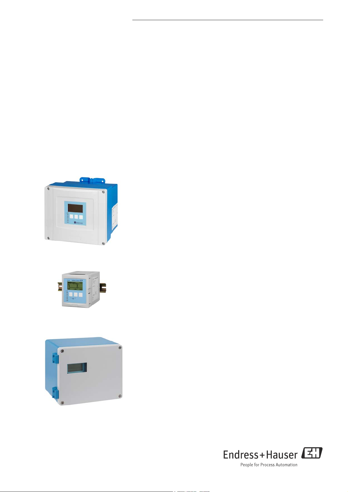
Prosonic S FMU90
Ultrasonic measurement
A universal device for level/flow measurement and
pump control
Transmitter for up to 2 sensors
FDU90/91/91F/92/93/95
Field of application
Level measurement of fluids and bulk materials with 1 or 2 sensors for measuring of
up to 45 m (148 ft) and level limit detection. Pump control, rake control and as option:
additional pump control function.
• Calculations: average, difference, sum
• Application flow: Flow measurement in open channels and weirs with 1 or 2 sensors
• Flow measurement with back water or sludge detection
• Up to 3 totalizers and 3 counters
• Counting or time pulse output for control of external units
• Transmitter available with field housing or top hat rail housing for control cabinet
instrumentation
Benefits
• Simple, menu-guided operation with 6-line plain text display, 15 languages
selectable
• Envelope curves on the display for simple diagnosis
• Easy operation, diagnosis and measuring point documentation with the supplied
"FieldCare" operating program
• Time-of-flight correction via integrated or external temperature sensors
• Linearisation (up to 32 points, freely configurable) for the most common flumes and
weirs pre-programmed and selectable
• Online calculation of the flume-/weir-flows via integrated flow curves
• Field housing aluminium with ATEX II 3D certificate
Page 2

Table of Contents
Prosonic S FMU90
Safety symbols . . . . . . . . . . . . . . . . . . . . . . . . . . . . . . . . . .3
Function and system design . . . . . . . . . . . . . . . . . . . . . .4
Measuring principle . . . . . . . . . . . . . . . . . . . . . . . . . . . . . . . . . . . 4
Blocking distance . . . . . . . . . . . . . . . . . . . . . . . . . . . . . . . . . . . . . . 4
Time-of-flight correction . . . . . . . . . . . . . . . . . . . . . . . . . . . . . . . 4
Interference echo suppression . . . . . . . . . . . . . . . . . . . . . . . . . . . 4
Pump control . . . . . . . . . . . . . . . . . . . . . . . . . . . . . . . . . . . . . . . . . 4
Linearization . . . . . . . . . . . . . . . . . . . . . . . . . . . . . . . . . . . . . . . . . . 5
Special functions . . . . . . . . . . . . . . . . . . . . . . . . . . . . . . . . . . . . . . 5
Datalog functions . . . . . . . . . . . . . . . . . . . . . . . . . . . . . . . . . . . . . . 5
Application examples for level measurements . . . . . . . . . . . . . 6
Application examples for flow measurements . . . . . . . . . . . . . 7
System integration HART . . . . . . . . . . . . . . . . . . . . . . . . . . . . . . . 8
System integration PROFIBUS DP . . . . . . . . . . . . . . . . . . . . . . . . 8
Input . . . . . . . . . . . . . . . . . . . . . . . . . . . . . . . . . . . . . . . . . .9
Sensor inputs . . . . . . . . . . . . . . . . . . . . . . . . . . . . . . . . . . . . . . . . . 9
External limit switches (option) . . . . . . . . . . . . . . . . . . . . . . . . . 9
External temperature sensor . . . . . . . . . . . . . . . . . . . . . . . . . . . . 9
Output . . . . . . . . . . . . . . . . . . . . . . . . . . . . . . . . . . . . . . . 10
Analog outputs . . . . . . . . . . . . . . . . . . . . . . . . . . . . . . . . . . . . . . 10
Relay outputs . . . . . . . . . . . . . . . . . . . . . . . . . . . . . . . . . . . . . . . . 10
PROFIBUS DP interface . . . . . . . . . . . . . . . . . . . . . . . . . . . . . . . . 11
Power supply . . . . . . . . . . . . . . . . . . . . . . . . . . . . . . . . . 11
Supply voltage / Power consumption / Current consumption 11
Galvanic isolation . . . . . . . . . . . . . . . . . . . . . . . . . . . . . . . . . . . . 11
Fuse . . . . . . . . . . . . . . . . . . . . . . . . . . . . . . . . . . . . . . . . . . . . . . . . 11
Electrical connection. . . . . . . . . . . . . . . . . . . . . . . . . . . 12
Terminal compartment of the field housing polycarbonate . . 12
Cable entries of the field housing polycarbonate . . . . . . . . . . 12
Terminal compartment of the field housing aluminium . . . . 12
Terminal compartment of the DIN-rail housing . . . . . . . . . . . 13
Terminal assignment . . . . . . . . . . . . . . . . . . . . . . . . . . . . . . . . . 15
Connection of the sensors FDU9x . . . . . . . . . . . . . . . . . . . . . . . 18
Synchronization line . . . . . . . . . . . . . . . . . . . . . . . . . . . . . . . . . . 19
Connection of the separate display and operating module . . 19
Connection of external switches
(for FMU90-********B***) . . . . . . . . . . . . . . . . . . . . . . . . . . . 20
Connection of a temperature sensor . . . . . . . . . . . . . . . . . . . . . 20
Performance characteristics . . . . . . . . . . . . . . . . . . . . 24
Reference operating conditions . . . . . . . . . . . . . . . . . . . . . . . . . 24
Maximum measuring error . . . . . . . . . . . . . . . . . . . . . . . . . . . . 24
Measuring error
Measured value resolution . . . . . . . . . . . . . . . . . . . . . . . . . . . . . 24
Measuring frequency . . . . . . . . . . . . . . . . . . . . . . . . . . . . . . . . . 24
Influence of the vapor pressure . . . . . . . . . . . . . . . . . . . . . . . . . 24
. . . . . . . . . . . . . . . . . . . . . . . . . . . . . . . . . . . . 24
Vibration resistance . . . . . . . . . . . . . . . . . . . . . . . . . . . . . . . . . . 24
Ingress protection . . . . . . . . . . . . . . . . . . . . . . . . . . . . . . . . . . . . 25
Electromagnetic compatibility (EMC) . . . . . . . . . . . . . . . . . . . . 25
Mechanical construction . . . . . . . . . . . . . . . . . . . . . . . 25
Housing versions . . . . . . . . . . . . . . . . . . . . . . . . . . . . . . . . . . . . . 25
Dimensions of the field housing polycarbonate . . . . . . . . . . . 25
Dimensions of the field housing aluminium . . . . . . . . . . . . . . 26
Dimensions of the DIN-rail housing . . . . . . . . . . . . . . . . . . . . . 26
Dimensions of the separate display and operating module . . 28
Weight . . . . . . . . . . . . . . . . . . . . . . . . . . . . . . . . . . . . . . . . . . . . . 28
Materials . . . . . . . . . . . . . . . . . . . . . . . . . . . . . . . . . . . . . . . . . . . 28
Operability . . . . . . . . . . . . . . . . . . . . . . . . . . . . . . . . . . . 30
Display and operating module . . . . . . . . . . . . . . . . . . . . . . . . . . 30
Operating menu . . . . . . . . . . . . . . . . . . . . . . . . . . . . . . . . . . . . . . 30
Basic setup . . . . . . . . . . . . . . . . . . . . . . . . . . . . . . . . . . . . . . . . . . 31
Locking of the instrument. . . . . . . . . . . . . . . . . . . . . . . . . . . . . 31
Certificates and Approvals. . . . . . . . . . . . . . . . . . . . . . 32
CE mark . . . . . . . . . . . . . . . . . . . . . . . . . . . . . . . . . . . . . . . . . . . . 32
RoHS . . . . . . . . . . . . . . . . . . . . . . . . . . . . . . . . . . . . . . . . . . . . . . . 32
RCM-tick mark . . . . . . . . . . . . . . . . . . . . . . . . . . . . . . . . . . . . . . . 32
EAC conformity . . . . . . . . . . . . . . . . . . . . . . . . . . . . . . . . . . . . . . 32
Ex approval . . . . . . . . . . . . . . . . . . . . . . . . . . . . . . . . . . . . . . . . . . 32
External standards and guidelines . . . . . . . . . . . . . . . . . . . . . . 32
Ordering information . . . . . . . . . . . . . . . . . . . . . . . . . . 33
Scope of delivery . . . . . . . . . . . . . . . . . . . . . . . . . . . . . . . . . . . . . 33
Accessories . . . . . . . . . . . . . . . . . . . . . . . . . . . . . . . . . . . 33
Commubox FXA195 HART . . . . . . . . . . . . . . . . . . . . . . . . . . . . 33
Commubox FXA291 . . . . . . . . . . . . . . . . . . . . . . . . . . . . . . . . . . 33
Protection cover for the field housing polycarbonate . . . . . . . 33
Mounting plate for the field housing polycarbonate . . . . . . . 34
Mounting bracket . . . . . . . . . . . . . . . . . . . . . . . . . . . . . . . . . . . . 34
Adaption plate for remote display . . . . . . . . . . . . . . . . . . . . . . . 35
Overvoltage protection HAW562 . . . . . . . . . . . . . . . . . . . . . . . 35
Temperature sensor Omnigrad S TR61 . . . . . . . . . . . . . . . . . . 38
Documentation . . . . . . . . . . . . . . . . . . . . . . . . . . . . . . . 39
Technical Information . . . . . . . . . . . . . . . . . . . . . . . . . . . . . . . . . 39
Operating instructions
(for transmitter FMU90) . . . . . . . . . . . . . . . . . . . . . . . . . . . . . . 39
Description of Instrument Functions . . . . . . . . . . . . . . . . . . . . 39
Safety Instructions . . . . . . . . . . . . . . . . . . . . . . . . . . . . . . . . . . . . 39
Environment . . . . . . . . . . . . . . . . . . . . . . . . . . . . . . . . . 24
Ambient temperature . . . . . . . . . . . . . . . . . . . . . . . . . . . . . . . . . 24
Storage temperature . . . . . . . . . . . . . . . . . . . . . . . . . . . . . . . . . . 24
Climate class . . . . . . . . . . . . . . . . . . . . . . . . . . . . . . . . . . . . . . . . . 24
2 Endress+Hauser
Page 3
Prosonic S FMU90
DANGER
WARNING
CAUTION
NOTICE
Safety symbols
Symbol Meaning
DANGER!
A0011189-DE
A0011190-DE
A0011191-DE
A0011192-DE
This symbol alerts you to a dangerous situation. Failure to avoid this situation will
result in serious or fatal injury.
WARNING!
This symbol alerts you to a dangerous situation. Failure to avoid this situation can
result in serious or fatal injury.
CAUTION!
This symbol alerts you to a dangerous situation. Failure to avoid this situation can
result in minor or medium injury.
NOTICE!
This symbol contains information on procedures and other facts which do not result
in personal injury.
Explosion
protection
0
-
.
Meaning
Device certified for use in explosion hazardous area
If the device has this symbol embossed on its name plate it can be installed in an
explosion hazardous area
Explosion hazardous area
Symbol used in drawings to indicate explosion hazardous areas. Devices located in
and wiring entering areas with the designation “explosion hazardous areas” must
conform with the stated type of protection.
Safe area (non-explosion hazardous area)
Symbol used in drawings to indicate, if necessary, non-explosion hazardous areas.
Devices located in safe areas still require a certificate if their outputs run into
explosion hazardous areas
Endress+Hauser 3
Page 4
Measuring principle
100%
0%
D
L
F
E
BD
V
Q
D
1
2
2
1
Prosonic S FMU90
Function and system design
L00-FMU90xxx-15-00-08-xx-900
1FDU9x
2Prosonic S FMU90
BD: blocking distance, D: distance from sensor membrane to fluid surface, E: empty distance F: span (full distance),
L: level, V: volume (or mass), Q: flow
The sensor transmits ultrasonic pulses in the direction of the product surface. There, they are reflected
back and received by the sensor. The transmitter Prosonic S measures the time t between pulse
transmission and reception. From t (and the velocity of sound c) it calculates the distance D from the
sensor membrane to the product surface:
D = c · t/2
From D results the desired measuring value:
• Level L
•Volume V
• Flow Q across measuring weirs or open channels
Blocking distance The span F may not extend into the blocking distance BD. Level echoes within the blocking distance
range can not be evaluated due to the transient characteristics of the sensor. The blocking distances of
the individual sensors are given in the following documents:
The blocking distances of the individual sensors are given in the following documents:
• TI00396F for the sensors FDU90/91/91F/92/93/95
1)
Time-of-flight correction In order to compensate for temperature dependent time-of-flight changes, a temperature sensor
(NTC) is integrated in the ultrasonic sensors.
Optionally, the Prosonic S FMU90 has an input for an external temperature sensor
(FMU90-********B***). The following sensor can be connected:
• Pt100
• Omnigrad S TR61 from Endress+Hauser
The external sensor must be used for the heated version of the ultrasonic sensors FDU90 and FDU91.
Interference echo suppression
Pump control Individually configurable for each pump:
The interference echo suppression feature of the Prosonic S ensures that interference echoes (e.g. from
edges, welded joints and installations) are not interpreted as a level echo.
• Pump switching delay, e.g. to prevent overload of the power supply system
• Backlash time and backlash interval, e.g. for complete draining of shafts or channels
• Crust reduction at pump shaft walls by fine adjustment of the switch point
1) The sensors FDU80/80F/81/81F/82/83/84/85/86/96 are not available anymore.
Use the serial number of your device to access the documentation for your device via www.endress.com.
4 Endress+Hauser
Page 5

Prosonic S FMU90
Linearization Pre-programmed linearization curves
Types of vessels
• Horizontal, cylindrical tank
•Spherical tank
• Tank with pyramidal bottom
• Tank with conical bottom
• Tank with flat, inclined bottom
Flow curves for flumes and weirs
• Khafagi-Venturi flume
•ISO-Venturi flume
3)
-Venturi flume
•BST
• Parshall flume
• Palmer-Bowlus flume
•Rectangular weir
• Rectangular constricted weir
4)
•NFX
•NFX
rectangular weir
rectangular constricted weir
• Trapezoidal weir
• V-notch weir
V-notch weir
•BST
•NFX V-notch weir
The pre-programmed linearization curves are calculated on-line.
Linearization formula for flow measurements
Q = C (h + h)
"h" is the upstream level. The parameters , , and C can be freely programmed.
Linearization table
consisting of up to 32 linearization points; to be entered manually or half-automatically.
Special functions • limit detection
•rake control
• alternating pump control or control according to pump rate (standard)
• option: additional pump control functions
– Alternation accordint to runtime or starts
– pump feedback via the optional digital inputs; stand-by pump configurable
– pump function test after resting time
– storm function to prevent unnecessary pump running times
– flush control for regular pump shaft cleaning
– pump control according to tariff times via digital input
– output of operating hours alarm or pump alarm
– recording of pump data (operating hours, number of starts, last running time)
• totalising of the flow volume with (resettable) counters and (non-resettable) totalisers
• triggering of a sampler by time or quantity pulses
• low flow cut off
• backwater detection in flumes
• sludge detection in flumes
• trend detection
2)
5)
:
Datalog functions • Peak hold indicator of the min./max. levels or flows and the min./max. temperatures at the sensors
• Recording of the last 10 alarms
• Indication of the operating status
• Trend indication of the outputs on the on-site display
• Indication of the operating hours
2) for instrument versions with flow software (FMU90 - *2********** or FMU90-*4**********)
3) BST: British Standard
4) French standard NFX 10-311
5) for instruments with software for additional pump control (FMU90-*3********** or FMU90-*4**********)
Endress+Hauser 5
Page 6
Prosonic S FMU90
min
Prosonic S
max
min
L
FDU9x
L
max
Prosonic S
L1 + L2
2
L1
L2
Prosonic S
D1
D2
M
L
Prosonic S
D
Prosonic S
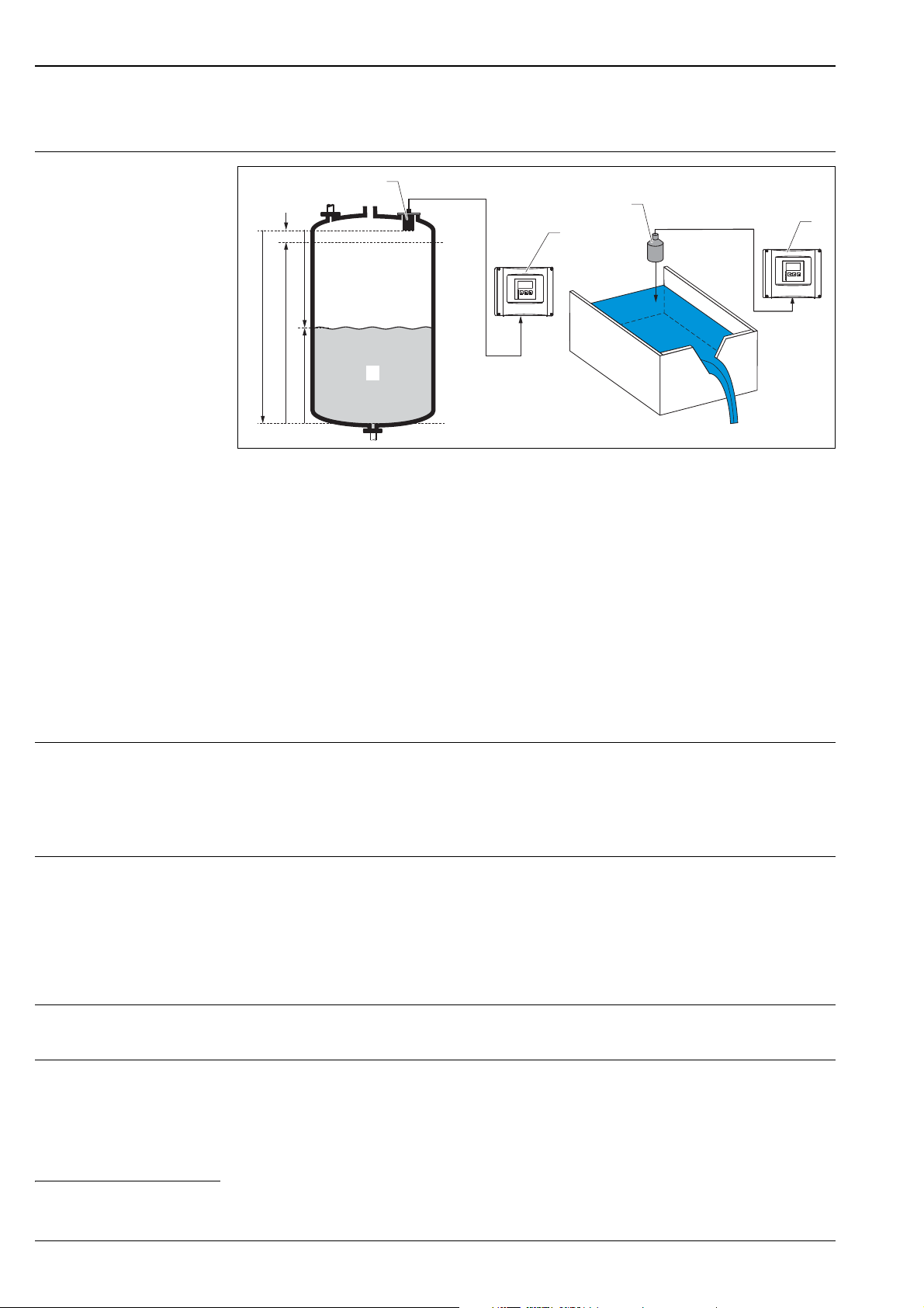
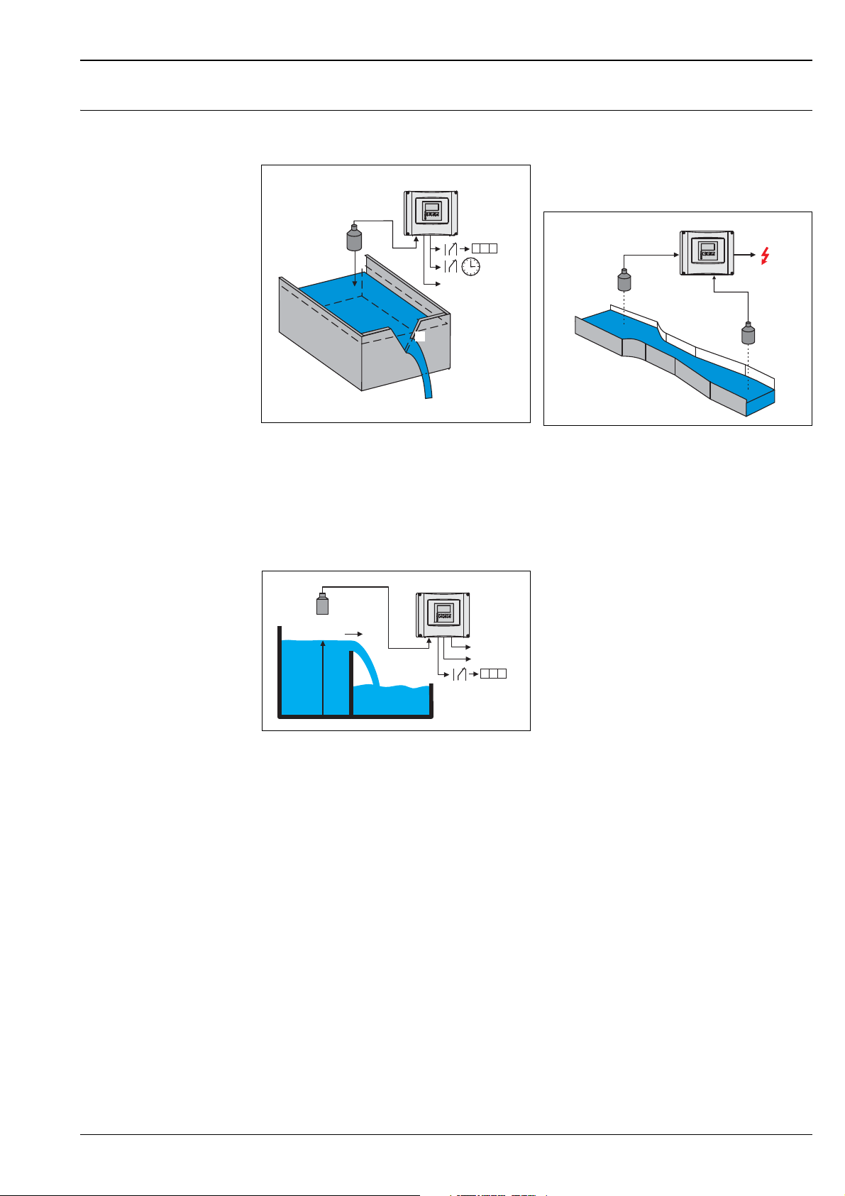
Application examples for level measurements
Level measurement with limit detection and
alarm output
L00-FMU90xxx-15-00-00-xx-010
Order code e.g.: FMU90 - *1***131****
(1 input, 3 relays, 1 outputs)
Rake control
(differential measurement)
Average level measurement
Order code e.g.: FMU90 - *1***212****
(2 inputs, 2 outputs)
Alternating pump control
(up to 6 pumps)
L00-FMU90xxx-15-00-00-xx-003
Order code e.g.: FMU90 - *1***212****
(2 inputs, 1 relay, 2 outputs)
L00-FMU90xxx-15-00-00-xx-004
Order code e.g.: FMU90 - *1***131****
(1 input, 3 relays)
L00-FMU90xxx-15-00-00-xx-007
Conveyor belt
L00-FMU90xxx-15-00-00-xx-005
6 Endress+Hauser
Order code e.g.: FMU90 - *1***111****
(1 input, 1 output)
Page 7
Prosonic S FMU90
FDU9x
D
Q
Prosonic S
123m
3
Q
Prosonic S
L
Q(l/s)
L (m)
Q (l/s)
Prosonic S
123m
3
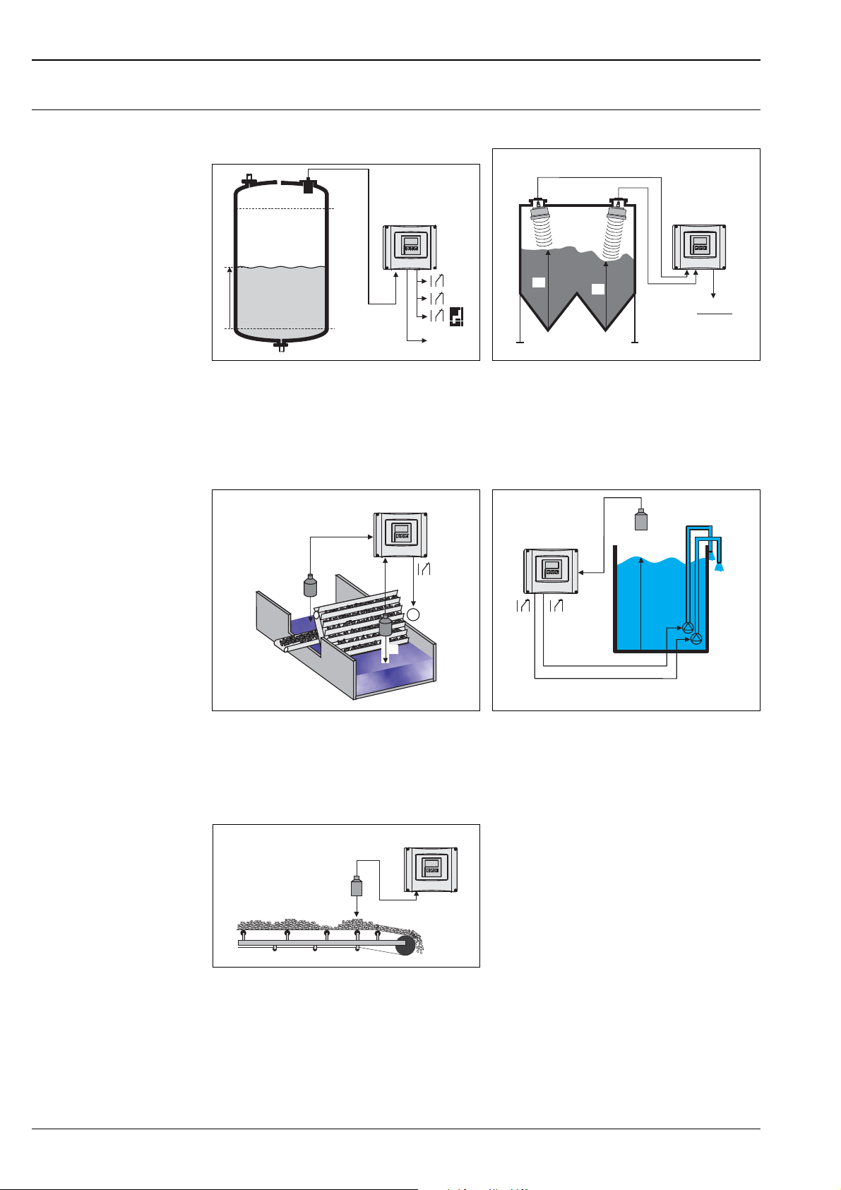
Application examples for flow measurements
Pulses for volume counter + time pulses (e.g.
for sampler)
L00-FMU90xxx-15-00-00-xx-011
Order code e.g.: FMU90 - *2***131****
(1 input, 3 relays, 1 output)
Stormwater overflow bassin
Simultaneous measurement of level L and flow Q
with 1 sensor.
Flow measurement with backwater alarm or
sludge detection
If the ratio "downstream level:upstream level"
rises above or falls below a critical value, an alarm
will be generated.
L00-FMU90xxx-15-00-00-xx-008
Order code e.g.: FMU90 - *2***212****
(2 inputs, 1 relay, 2 outputs)
L00-FMU90xxx-15-00-00-xx-006
Order code e.g.: FMU90 - *2***112****
(1 input, 2 outputs)
Endress+Hauser 7
Page 8
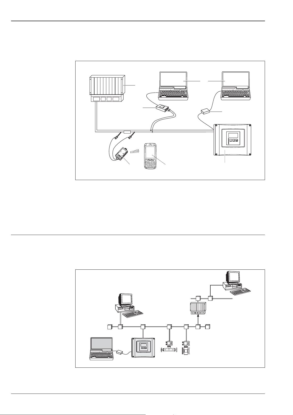
System integration HART Operating options
250 W
I : 4...20 mA + HART
1
5
4
3
1
2
7
6
PROFIBUS DP
SPS /
PLC/
API
Ethernet
PDM
...
Prosonic S
PROFIboard
PROFIcard
PROFIusb
Commubox
FXA 291
FieldCare
T
T
FieldCare
In the standard version a HART signal is superimposed onto the first output current. In order to use the
HART communication, the circuit must contain a communication resistor of 250 .
Prosonic S FMU90
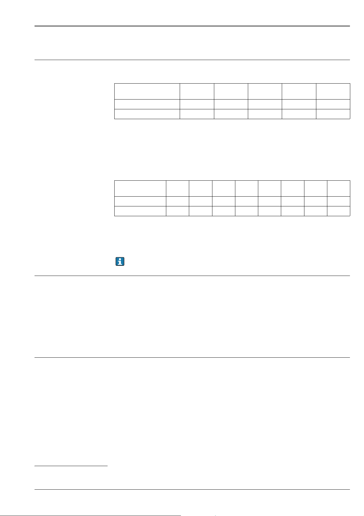
System integration PROFIBUS DP
L00-FMU90xxx-14-00-00-xx-020
1 SPS, PLC, API
2 Commubox FXA195 (USB), HART-Protocol
3 FieldCare
4 Commubox FXA291 (service interface)
5 Operating and display module at the Prosonic S (if present)
6 Field Xpert SFX350/SFX370
7 VIATOR Bluetooth-Modem with connection cable
Operating options
• Via the display and operating module at the Prosonic S
• Via the service interface with the Commubox FXA291 and the operating program FieldCare
• Via PROFIBUS DP with PROFIboard, PROFIcard or PROFIusb and the operating program FieldCare
L00-FMU90xxx-14-00-00-xx-021
8 Endress+Hauser
Page 9
Prosonic S FMU90
Input
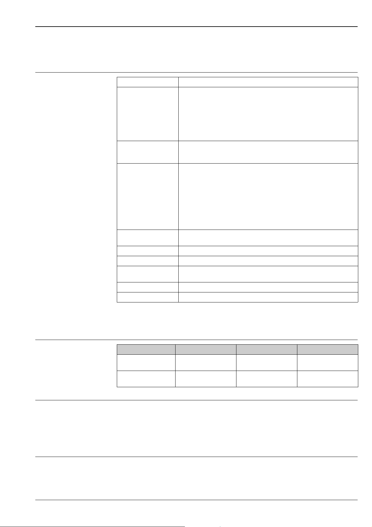
Sensor inputs Depending on the instrument version, 1 or 2 of the sensors FDU90, FDU91, FDU91F, FDU92, FDU93,
FDU95 can be connected. The Prosonic S identifies these sensors automatically.
Sensor FDU90
Max. range
Max. range
m (ft)
1) This table gives the maximum range. The range depends on the measuring conditions. For an estimation
see Technical Information TI00396F, Chapter "Input".
1)
in liquids
1
in solids 1.2 (3.9) 5 (16) 10 (33) 15 (49) 45 (148)
3 (9.8) 10 (33) 20 (66) 25 (82) -
FDU91
FDU91F
In order to support existing installations, the following sensors can be connected as well.
FDU92 FDU93 FDU95
6)
The type of
sensor must be entered manually (except FDU96).
Sensor
Max. range
Max. range
m (ft)
1) This table gives the maximum range. The range depends on the measuring conditions. For an estimation
1)
in liquids
1
in solids 2 (6.6) 5 (16) 10 (33) 15 (49) 25 (82) 45 (148) 70 (230) 70 (230)
see Technical Information TI00189F, Chapter "Planning Recommendations".
FDU80
FDU80F
5 (16) 10 (33) 20 (66) 25 (82) - - - -
FDU81
FDU81F
FDU82 FDU83 FDU84 FDU85 FDU86 FDU96
The sensors FDU83, FDU84, FDU85 and FDU86 with an ATEX, FM or CSA certificate are not
certified for connection to the FMU90 transmitter.
External limit switches (option)
Optionally, the Prosonic S FMU90 has 4 inputs for external limit switches (FMU90-********B***).
Switching options
• External passive limit switch (NC/NO switch)
• 0: < 8 V; 1: > 16 V
Usage (examples)
• Pump feedback (for FMU90-*3******B*** and FMU90-*4******B***)
• Pump tariff control (for FMU90-*3******B*** and FMU90-*4******B***)
• Start/stop/reset of daily counters for flow measurements
(for FMU90-*2******B*** and FMU90-*4******B***)
• Min/max level detection, e.g. by Liquiphant
External temperature sensor Optionally, the Prosonic S FMU90 has an input for an external temperature sensor
(FMU90-********B***).
Connectable sensors
• Pt100 (3-wire or 4-wire connection)
A Pt100 with 2-wire connection may not be used due to its insufficient accuracy.
• Omnigrad S TR61 (from Endress+Hauser) ä 33, "Accessories"
Usage (example)
• Time-of-flight correction for a heated sensor (FDU90-***B*, FDU91-***B*).
6) The sensors FDU80/80F/81/81F/82/83/84/85/86/96 are not available anymore.
Use the serial number of your device to access the documentation for your device via www.endress.com.
Endress+Hauser 9
Page 10

Output
Prosonic S FMU90
Analog outputs
Relay outputs
Number 1 or 2, depending on instrument version
Output signal Active current output
output values configurable at the instrument:
• 4 to 20 mA with HART
1)
• 0 to 20 mA without HART
Signal on alarm • For setting 4 to 20 mA, selectable:
–MIN: -10% (3,6mA)
– MAX: 110 % (22 mA)
– HOLD (last current value is held)
– User specific
• For setting 0 to 20 mA:
– MIN: 110 % (21,6 mA)
– HOLD (last current value is held)
– User specific
Output damping Freely selectable, 0 to 1000 s
Load Max. 600 , influence negligible
Max. ripple U
Max. noise U
= 200 mV at 47 to 125 Hz (measured at 500 )
SS
= 2,2 mV at 500 Hz to 10 kHz (measured at 500 )
eff
1) The HART signal is assigned to the first analog output. The second analog output does not carry a HART
signal.
Number 1, 3 or 6; depending on the instrument version
Type Potential-free relay, SPDT, can be inverted
Assignable functions • Limit (inband, out-of-band, trend, level limit)
• Counting pulse
• Time pulse
• Alarm/diagnosis
(e.g. indication of backwater
for flow counting (max. frequency 2 Hz; pulse width adjustable)
(max. frequency 2 Hz; pulse width adjustable)
1)
, sludge, echo loss etc.)
• Pump control (alternating/fixed limit/pump rate)
• For FMU90-*3********** and FMU90-*4**********):
additional pump control (standby pump, storm function to avoid unnecessary
run times of the pumps, pump function test, flush control to clean pump shafts,
operating hours alarm, pump alarm)
• Rake control (difference or relative measurement)
• Fieldbus relay (to be switched direclty from the PROFIBUS DP-bus)
Switching power • DC voltage: 35 V
, 100 W
DC
• AC voltage: 4 A, 250 V, 1000 VA at cos = 0,7
State on error Selectable:
• HOLD (last value is held)
•Energized
• Ee-energized
• Present value is used
Behaviour after power
Switch-on delay selectable
failure
2)
LEDs
A yellow LED on the front panel is allocated to each relay, which lights if the relay
is energized.
The LED of an alarm relay lights during normal operation.
The LED for a pulse relay briefly flashes at every pulse.
1) For instrument versions with flow software (FMU90 - *2**********)
2) For instrument versions with display and operating module
10 Endress+Hauser
Page 11
Prosonic S FMU90
PROFIBUS DP interface
Profile 3.0
Transmittable values • Main value (level or flow, depending on the instrument version)
•Distances
•Counters
• Temperatures
• Average/difference/sum
• Relay states
•Rake control
•Pump control
Function blocks • 10 Analog Input Blocks (AI)
Supported baud rates • 9.6 kbaud
Service Access Points
(SAPs)
ID number 1540 (hex) 1540 (hex) = 5440 (dec)
GSD file EH3x1540.gsd
Addressing Via dip switches at the instrument or via software (e.g. FieldCare).
Termination Can be activated/deactivated in the instrument.
Locking The device can be locked by hardware or software.
• 10 Digital Input Blocks (DI)
• 10 Digital Output Blocks (DO)
• 19.2 kbaud
• 45,45 kbaud
• 93.75 kbaud
• 187.5 kbaud
• 500 kbaud
•1.5Mbaud
•3Mbaud
•6Mbaud
•12Mbaud
1
Default address: 126 per software
Power supply
Supply voltage / Power consumption / Current consumption
Galvanic isolation The following terminals are galvanically isolated from each other:
Fuse •2AT/DC
Endress+Hauser 11
Instrument version Supply voltage Power consumption Current consumption
AC voltage
(FMU90 - ****A****)
DC voltage
(FMU90 - ****B****)
90 to 253 V
10,5 to 32 V
(50/60 Hz) Max. 23 VA Max. 100 mA at 230 V
AC
DC
Max. 14 W (typically 8 W) Max. 580 mA at 24 V
• Auxiliary energy
• Sensor inputs
•Analog output 1
•Analog output 2
•Relay outputs
•Bus connection (PROFIBUS DP)
• 400 mA T /AC
Accessible in the terminal compartment
AC
DC
Page 12
Electrical connection
1.
2.
3.
1.
2.
Prosonic S FMU90
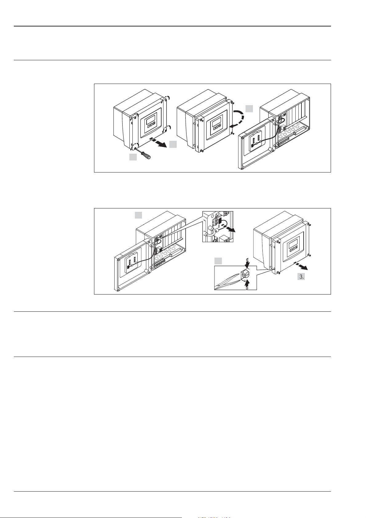
Terminal compartment of the field housing polycarbonate
The field housing has a separate terminal compartment. It can be opened after loosening the 4 screws
of the lid.
L00-FMU90xxx-04-00-00-xx-002
For easier wiring, the lid can be completely removed by unplugging the display plug and loosening the
hinges:
Cable entries of the field housing polycarbonate
Terminal compartment of the field housing aluminium
L00-FMU90KAx-04-00-00-xx-009
On the bottom of the housing the following openings for cable entries are prestamped:
• M20x1.5 (10 openings)
• M16x1.5 (5 openings)
• M25x1.5 (1 opening)
A suitable cutting device must be used for cutting out the openings.
The field housing aluminium is wired almost the same way as the FMU90 in the DIN-rail housing
ä 13.
Pay attention to the following differences:
• In explosion-hazardous areas, all connections must be located inside the field housing aluminium.
. Exception: For potential equalization, there’s a terminal block inside the housing that is wired
to the FMU90 ex works. The terminal block is connected to the protective earth terminal, which
is accessible on the outside of the field housing aluminium.
For wiring inside the housing, the cables are routed into the housing through the cable entries in
the bottom and are connected there with either the device or a terminal block. When routing the
cables through the cable entries, use cable glands that are appropriate for the ignition protection
type!
• If the distance to the sensors is greater than 30 m (98 ft), an extension cable must be used.
12 Endress+Hauser
Page 13

Prosonic S FMU90
HINWEIS
M
a
d
Mad
D
-
7
9
6
D-79
6
P
r
o
Pro
Ta
>
Ta >
X
a
x
x
X
a
x
x
D
a
t
.
/
D
at./
X
=
X
=
1
O
r
d
e
Orde
S
e
r
.
-
Ser.-
5
2
3
4
1
1.
2.
A0033256
1 Field housing aluminium, housing opened
2Nameplate
3 Protective earth terminal
4 Display and operating module
5 Field housing aluminium, housing closed
Cable entries
At the bottom of the housing are 12 cable entries M20x1,5 located :
Terminal compartment of the DIN-rail housing
When routing the cables through the cable entries, use cable glands that are appropriate for the
ignition protection type!
Single instrument
L00-FMU90xxx-04-00-00-xx-003
The catch can be unlocked by slightly pressing onto the clip. Then, the cover of the terminal
compartment can be opened.
Endress+Hauser 13
Page 14

Several instruments mounted side by side
1.
2.
3.
1.
2.
3.
Prosonic S FMU90
L00-FMU90xxx-04-00-00-xx-012
Open the catch of the cover (e.g. by a screwdriver).
Pull the cover out by approx. 20 mm (0.79 in) .
The cover can now be opened.
• The cables can be inserted into the housing from above or from below.
• The pictures show the smallest housing version but are valid for the larger versions as well.
• If the instruments are mounted next to each other and if the sensor cables run in parallel, the
synchronization terminals (39 and 40) must be interconnected (see sections ä 15 "Terminal
assignment" and ä 19 "Synchronization line").
14 Endress+Hauser
Page 15

Prosonic S FMU90
FDU-
Sensor
0/4...20mA
1
42
41
Relay
55
52
54
51
53
50
3
Address
Term.
DP
off
on
off
on
SW
HW
1
2
3
4
5
6
7
8
1
2
3
4
A(N)
66
B(P)
65
Display
POWER
HART
0/4…20mA
Sync
Fuse
I
1
FDU
-
Sensor
RD
11
BK
10
YE
9
40
39
5
4
67
8
1
1
Service
Relay
32
1
A
B
C
E
2
58
5756
4
61
6059
5
64
6362
6
RD
11
BK
10
YE
9
2
RD
14
BK
13
YE
12
I
2
FDU
-
Sensor
DigIn
76
73
75
72
74
71
2
D
1
7979
787877
3
82
8180
4
85
8483
Temp.
Terminal assignment Pluggable spring-force terminals for connection of the cables are supplied in the terminal
compartment. Rigid conductors or flexible conductors with cable sleeve can directly be inserted and are
contacted automatically.
Feature Value
Conductor cross section 0,2 mm
Cable and sleeve cross section 0,25 mm
2
to 2,5 mm2 (26 to 14 AWG)
2
to 2,5 mm2 (24 to 14 AWG)
Min. stripping length 10 mm (0.39 in)
The terminal configuration depends on the instrument version ordered. There is a basic terminal area,
which is present in every instrument version. Additional optional terminal areas are only present if the
respective option has been selected in the product structure.
Terminal area Present for the following instrument versions
Basic area A For all versions
For instrument versions with 2 sensor inputs and/or 2 analog outputs
B
(FMU90 - *****2****** and/or FMU90 - *******2****)
For instrument versions with 3 or 6 relays
C
Optional areas
(FMU90 - ******3***** oder FMU90 - ******6*****)
For instruments with external switch inputs and external temperature input
D
(FMU90 - ********B***)
For instrument versions with PROFIBUS DP interface
E
(FMU90 - *******3****)
L00-FMU90xxx-04-00-00-xx-001
Endress+Hauser 15
Terminals of the Prosonic S (the terminals depicted in grey are not present in every instrument version)
A Basic terminal area
B – E Optional terminal areas (present if the respective option has been selected in the product structure)
The depicted switching states of the relays refer to the de-energized state.
Page 16

Prosonic S FMU90
Terminals Meaning Terminal
Remarks
area
Auxiliary energy
1, 2
• L (für AC version)
•L+ (for DC version)
2•N (for AC version)
•L- (for DC version)
A
A
Depending on instrument version:
• 90 to 253 V
• 10,5 to 32 V
AC
DC
3 Potential equalization A
Fuse A Depending on instrument version:
•400mAT (for AC)
•2AT (for DC)
Analog outputs (not available for PROFIBUS DP instruments)
Analog output 1;
4, 5
4 to 20 mA with HART/
A Not present for the PROFIBUS DP version
0 to 20 mA w/o HART
41, 42
Analog output 2 (optional);
4 to 20 mA/
0 to 20 mA
B
Only for the version with two analog outputs;
no HART signal at this output
Relay outputs
6, 7, 8 Relay 1 A
50, 51, 52 Relay 2 (optional) C Only for the versions with 3 or 6 relays
53, 54, 55 Relay 3 (optional) C Only for the versions with 3 or 6 relays
56, 57, 58 Relay 4 (optional) C Only for the version with 6 relays
59, 60, 61 Relay 5 (optional) C Only for the version with 6 relays
62, 63, 64 Relay 6 (optional) C Only for the version with 6 relays
Bus communication (only available for PROFIBUS DP instruments)
65 PROFIBUS A (RxT/TxD - N) D
Only for the PROFIBUS DP version
66 PROFIBUS B (RxT/TxD - P) D
Synchronization
39, 40 Synchronization A See section 4.6, "Synchronization line"
Level inputs
9 (YE),
10 (BK),
11 (RD)
12 (YE),
13 (BK),
14 (RD)
Sensor 1 (FDU8x/9x)
YE: yellow strand
BK: black strand
RD: red strand
Sensor 2 (FDU8x/9x) (optional)
YE: yellow strand
BK: black strand
RD: red strand
• A: for versions with 1 sensor input
• B: for versions with 2 sensor inputs
1)
B Only for the version with 2 sensor inputs
External switch inputs
71, 72, 73 External switch input 1 D 0: < 8 V or 72 and 73 interconnected
1: > 16 V or 72 and 73 not interconnected
74, 75, 76 External switch input 2 D 0: < 8 V or 75 and 76 interconnected
1: > 16 V or 75 and 76 not interconnected
77, 78, 79 External switch input 3 D 0: < 8 V or 78 and 79 interconnected
1: > 16 V or 78 and 79 not interconnected
80, 81, 82 External switch input 4 D 0: < 8 V or 81 and 82 interconnected
1: > 16 V or 81 and 82 not interconnected
16 Endress+Hauser
Page 17

Prosonic S FMU90
CAUTION
!
Terminals Meaning Terminal
area
Temperature input
83, 84, 85 Temperature input:
•PT100
• Omnigrad S TR61
(Endress+Hauser)
1) In this case, terminals 9/10/11 are not present on terminal area A.
D See section
Remarks
"Connection of a temperature sensor"
Limitation of electrical safety.
‣ When using the public supply mains, an easily accessible power switch must be installed in the
proximity of the device. The power switch must be marked as a disconnector for the device
(IEC/EN 61010).
In order to avoid interference, do not route the sensor cables parallel to high-voltage or electric
power lines and not close to frequency converters.
Additional elements on the terminal areas
Designation Meaning/Remarks
Fuse Fuse: 2 A T /DC or 400 mA T/AC
Display Connection of the display or the remote display and operating module
Service Service interface for connection of a PC/Notebook via Commubox FXA291
Locking switch
Term. Bus termination (only applicable for instruments with PROFIBUS interface)
Address Bus address (only applicable for instruments with PROFIBUS interface)
Endress+Hauser 17
Page 18

Connection of the sensors
YE
9
(12)
BK
10
(13)
RD
11
(14)
FDU90/91/92
BK
YE
RD
1
YE
9
(12)
BK
10
(13)
RD
11
(14)
FDU91F/93/95
BK
YE
RD
GNYE
2
3
FMU90
2
3
FMU90
YE
9
(12)
BK
10
(13)
RD
11
(14)
FDU90/91
BK
YE
RD
FMU90
BN BU
24 VDC
+
-
A
B
C
YE
9
(12)
BK
10
(13)
RD
11
(14)
FDU91F/93/95
BK
YE
RD
GNYE
FMU90
D
300 m
(984 ft)
≤
≤30 m
(98 ft)
1
300 m
(984 ft)
≤
≤30 m
(98 ft)
FDU9x
Prosonic S FMU90
A Without sensor heater
B With sensor heater
C Grounding at the terminal box
D Grounding at the transmitter FMU90
1 Screen of the sensor cable
2Terminal box
3 Screen of the extension cable
Colours of the strands: YE = yellow; BK = black; RD = red; BU = blue; BN = brown; GNYE = green-yellow
For details refer to Technical Information TI00396F7).
L00-FDU9xxxx-04-00-00-xx-002
7) The sensors FDU80/80F/81/81F/82/83/84/85/86/96 are not available anymore.
Use the serial number of your device to access the documentation for your device via www.endress.com.
18 Endress+Hauser
Page 19

Prosonic S FMU90
Prosonic S
FMU90/95
39 40
1
23
20
……
FMU90 FMU90 FMU90
Prosonic S
FMU90/95
39 40
Prosonic S
FMU90/95
39 40
Prosonic S
FMU90/95
39 40
Prosonic
FMU860/861/862
63 64
1
2
10
……
FMU90
VH
Display
POWER
HART
0/4…20mA
Sync
Fuse
I
1
FDU-
Sensor
RD
11
BK
10
YE
9
40
39
5
4
6
7
8
Service
Relay
3
2
1
1
Synchronization line
• If wiring several Prosonic S (FMU90/FMU95)
which are mounted in a common cabinet and if
the sensor cables run in parallel, the
synchronization terminals (39 and 40) must be
interconnected.
• Up to 20 instruments can be synchronized in
this way.
• The synchronization prevents an evaluation
unit from receiving a signal while a different
evaluation unit is emitting a signal.
This prevents pulses in the sensor cable of one
sensor from influencing the received signal on
the cable of a different sensor.
• If there are more than 20 instruments, groups
must be formed, each containing a maximum of
20 instruments. For the instruments within
each group, the sensor cables may run in
parallel. The sensor cables of different groups
must be seperated from each other.
• Usual commercial screened cable can be used
for synchronization
– Max. length: 10 m (33 ft) between the
individual instruments
– cross section: 2 x (0.75 to 2.5 mm
2
(18 to 14 AWG))
– for lengths up to 1 m (3.3 ft), an unscreened
cable can be used; for lenghts exceeding 1 m
(3.3 ft), screening is required. The screen
must be connected to ground
• Instruments of the Prosonic FMU86x family
can be connected to the synchronization line as
well. In this case a maximum of 10 instruments
can be connected to each synchronisation line.
L00-FMU90xxx-04-00-00-xx-004
L00-FMU90xxx-04-00-00-xx-017
Connection of the separate display and operating module
L00-FMU90xxx-04-00-00-xx-005
1 Connection of the display plug with the cable (3 m (9.8 ft))
For the version of the Prosonic S with a separate display for panel mounting, a pre-assembled
connecting cable (3 m (9.8 ft)) is supplied. The cable must be connected to the display plug of the
Prosonic S.
Minimum diameter for cable bushing: 20 mm (0.79 in)
Endress+Hauser 19
Page 20

Connection of external
PNP
FMU90 FMU90
FTL
A
B
FMU90
C
24 V
(24 V)
71 72 73
74 75 76
77 78 79
80 81 82
(24 V)
71 72 73
74 75 76
77 78 79
80 81 82
(24 V)
71 72 73
74 75 76
77 78 79
80 81 82
switches
(for FMU90-********B***)
Prosonic S FMU90
L00-FMU90xxx-04-00-00-xx-021
ALiquiphant
B External switch
C External switch with external supply voltage
Connection of a temperature sensor
The maximum short-circuit current at 24 V is 20 mA.
The Prosonic S FMU90 transmitter has an optional input for an external temperature probe (in the
product structure: feature 90 "Additional input", option B, ä 33). The following probes can be
connected:
• a Omnigrad S TR61 temperature probe from Endress+Hauser
• a Pt100 temperature probe
• After connecting an external temperature sensor, the following is required:
1. The ty pe of t he con necte d sensor (Pt100 or Omnigrad S TR61) mu st be s elected i n "sensor
management/ext. temp. sensor" in the "sensor type" parameter.
2. The external temperature sensor must be assigned to an ultrasonic sensor in "sensor
management/FDU sensor/US sensor N" in the "temp. measurement" parameter.
If the option "alarm" has been selected for the case of an error in external temperature sensor, this
alarm is indicated by the alarm relay.
Omnigrad S TR61 (Endress+Hauser) (connectable to FMU90-********B***)
In case an external temperature sensor is needed, an Omnigrad S TR61 can be used. See ä 38 for
examples for exact order codes for a TR61 temperature sensor.
Outside of explosion-hazardous areas, the following types of Omnigrad S TR61 with ceramic
terminal block (no head transmitter) can be used:
• TR61-A***********
20 Endress+Hauser
Page 21

Prosonic S FMU90
83 84
FMU90
85
EX
EX
↑↑
RD
A0033412
RD Cable color = Red
More information can be found in the following documents:
• TI01029T
Endress+Hauser 21
Page 22

Prosonic S FMU90
HINWEIS
83
84
FMU90
85
EX
83 84
FMU90
85
A
B
EX
EX
EX
↑↑
RD
↑↑
RD
Omnigrad S TR61 for explosion-hazardous areas (Endress+Hauser) (connectable to FMU90********B***)
For explosion-hazardous areas, an Omnigrad S TR61 with ceramic terminal block (no head
transmitter) can be used, which has appropriate approval for the corresponding area.
In connection with the FMU90, only those variants of the Omnigrad S TR61 can be used which do
not rely on intrinsic safety. Depending on the conditions of the individual explosion-hazardous area,
suitable types can be for instance the following:
• TR61-E***********
• TR61-H***********
• TR61-M***********
• TR61-N***********
• TR61-R***********
• TR61-S***********
• TR61-2***********
• TR61-3***********
Devices for use in hazardous environments are accompanied by separate "Ex documentation"
(XA), which is an integral part of the documentation. Strict compliance with the installation
instructions and ratings as stated in this Additional documentation is mandatory.
AEx area
B Ex area, with connection via terminal box
RD Cable color = Red
More information can be found in the following documents:
• TI01029T
22 Endress+Hauser
A0033403
Page 23

Prosonic S FMU90
WARNING
!
83 84 85
A
Pt100
83 84
FMU90
85
Pt100
B
Pt100 (connectable to FMU90-********B***)
L00-FMU90xxx-04-00-00-xx-020
A Pt100 with 3-wire connection
B Pt100 with 4-wire connection (one connector remains unused)
A Pt100 with 2-wire-connection may not be used due to its insufficient measuring accuracy.
Explosion hazard!
A Pt100 must not be connected in explosion hazardous areas.
‣ In explosion hazardous areas, use an Omnigrad S TR61.
Endress+Hauser 23
Page 24

Performance characteristics
Prosonic S FMU90
Reference operating conditions
• Temperature = 24±5 °C (75±9 °F)
• Pressure = 960±100 mbar (14±1.45 psi)
• Relative humidity = 60±15 %
• Ideally reflecting surface, sensor vertically aligned
(e.g. calm, plane liquid surface of 1 m
• No interference echoes within the signal beam
• Settings of the application parameters:
– Tank shape = flat ceiling
– Medium property = liquid
– Process condition = calm surface
Maximum measuring
8) 9)
error
Measuring error
±0.2 % of the maximum span of the sensor
Includes linearity, repeatability, and hysteresis
±2 mm (0.08 in) + 0.17 % of the measured distance
Measured value resolution 1mm (0.04in) with FDU90/FDU91
Measuring frequency Max. 3 Hz
The exact value depends on the settings of the application parameters and the instrument version.
The maximum measuring frequency is obtained for "empty E" 2m ( 6.6 ft) and "process
condition" = "test: no filter".
2
(10.76 ft2))
Influence of the vapor pressure
The vapor pressure at 20 °C (68 °F) gives a hint on the accuracy of the ultrasonic level measurement. If
the vapor pressure at 20 °C (68 °F) is below 50 mbar (1 psi), ultrasonic level measurement is possible
with a very high accuracy. This is valid for water, aqueous solutions, water-solid-solutions, dilute acids
(hydrochloric acid, sulfuric acid, ...), dilute bases (caustic soda, ...), oils, greases, slurries, pastes, ...
High vapor pressures or outgassing media (ethanol, acetone, ammonia, ...) can influence the accuracy.
If conditions like these are present, please contact Endress+Hauser: http://www.endress.com/contact
Environment
Ambient temperature 40 to 60 °C (40 to 140 °F)
The functionality of the LC display becomes restricted at TU < 20 °C ( TU < 4°F).
If the device is operated outdoors in strong sunlight, a protective cover should be used ( ä 33).
Storage temperature 40 to 60 °C (40 to 140 °F)
Climate class • Field housing polycarbonate: according to DIN EN 60721-3 4K2/4K5/4K6/4Z2/4Z5/4C3/4S4/
4M2 (DIN 60721-3 4K2 corresponds to DIN 60654-1 D1)
• Field housing aluminium: according to DIN EN 60721-3 4K2/4K5/4K6/4Z2/4Z5/4C3/4S4/4M2
(DIN 60721-3 4K2 corresponds to DIN 60654-1 D1)
• Housing for DIN rail mounting: according to
DIN EN 60721-3 3K3/3Z2/3Z5/3B1/3C2/3S3/3M1
(DIN 60721-3 3K3 corresponds to DIN 60654-1 B2)
2)2
Vibration resistance • Housing for DIN rail: DIN EN 60068-2-64 / IEC 68-2-64; 20 to 2000 Hz; 0,5 (m/s
• Field housing polycarbonate: DIN EN 60068-2-64 / IEC 68-2-64; 20 to 2000 Hz; 1,0 (m/s
• Field housing aluminium: DIN EN 60068-2-64 / IEC 68-2-64; 20 to 2000 Hz; 1,0 (m/s
/Hz
2)2
2)2
/Hz
/Hz
8) according to EN 61298-2
9) with reference operating conditions
24 Endress+Hauser
Page 25

Prosonic S FMU90
215 (8.46)
180 (7.09)
150 (5.91)
15 (0.59)
170 (6.69)
190 (7.48)
80
(3.15)
100
(3.94)
ø6.5 (0.26)
10 (0.39)
A
B
»1,6 kg (3.53 lbs)
153 (6.02)
C
³
55 (2.17)
³
55 (2.17)
Ingress protection • Field housing polycarbonate: IP66 / NEMA 4x
• Field housing aluminium: IP66 / NEMA 4x
• Housing for DIN rail: IP20
• Separate display:
– IP65 / NEMA 4 (front panel, if mounted in cabinet door)
– IP20 (rear panel, if mounted in cabinet door)
Electromagnetic compatibility (EMC)
Electromagnetic compatibility according to all relevant requirements of the EN 61326- series and
NAMUR recommendation EMC (NE21). For details see declaration of conformity.
With respect to interference emission the devices meet the requirements of class A and are only
provided for use in an "industrial environment"!
Mechanical construction
Housing versions • Field housing polycarbonate; optionally with integrated display and operating module
• Field housing aluminium; optionally with integrated display and operating module
• Housing for top-hat rail mounting; optionally with integrated display and operating module
• Housing for top-hat rail mounting with separated display and operating module for cabinet door
mounting
Dimensions of the field housing polycarbonate
L00-FMU90xxx-06-00-00-xx-001
Dimensions in mm (in)
A Mounting help (supplied); can also be used as drilling template
B Field housing polycarbonate
C Minimum mounting distance
The dimensions of the field housing polycarbonate are the same for all instrument versions.
To open the housing, a minimum mounting distance of 55 mm (2.17 in) is required on the left.
The mounting help must be mounted on a plane surface and must not become bent. Otherwise
the mounting of the field housing polycarbonate may be difficult or impossible.
Endress+Hauser 25
Page 26

Dimensions of the field
180 (7.09)
180 (7.09)
202 (7.95)
181 (7.13)
232 (9.13)
≥55 (2.17) ≥55 (2.17)
housing aluminium
Prosonic S FMU90
Dimensions of the DIN-rail housing
Dimensions in mm (in)
The dimensions of the field housing aluminium are the same for all instrument versions.
To open the housing, a minimum mounting distance of 55 mm (2.17 in) is required on the left.
The dimensions of the DIN-rail housing depend on the instrument version. The version determines,
which terminal areas the Prosonic S contains. The dimensions are influenced by the following features
of the product structure:
• 60: Level Input
• 70: Switch Output
• 80: Output
In order to determine the dimensions of a specific version, perform the following steps (see the
example ä 27):
1. Using the product structure, determine the options of the features 60, 70 and 80 of the
instrument version in question.
10 20 30 40 50 60 70 80 90 100 110 120
FMU90 -
2. Using the following table, determine how many optional terminal areas this instrument version
contains.
Feature and option of
the product structure
Feature 60; option 2
and/or
feature 80, option 2
Corresponds to the following
terminal area
2 sensor inputs
and/or
2 analog outputs
Present?
yes = 1
no = 0
A0033258
Feature 70, option 3 or 6 3 o 6 relays
26 Endress+Hauser
Page 27

Prosonic S FMU90
92 (3.62)
104 (4.09)
140(5.51)
43(1.69)
EN 60715
TH 35x7.5/15
(1.4x0.3/0.6)
35 (1.38)
0,5 kg (1.10 lbs)»
150 (5
.91)
104 (4.09)
140(5.51)
EN 60715
TH 35x7.5/15
(1.4x0.3/0.6)
35 (1.38)
»0,7 kg (1.54 lbs)
42(1.65)
210 (8.27)
140(5.51)
EN 60715
TH 35x7.5/15
(1.4x0.3/0.6)
35 (1.38)
»0,9 kg (1.98 lbs)
42(1.65)
104 (4.09)
232
A
Feature 80, option 3 PROFIBUS DP interface
Feature 90, option B
Inputs for external switches and
external temperature sensor
Sum =
3. The appropriate dimensions are given in the following diagram:
Sum = 0
(only basic terminal area)
Sum = 1, 2 or 3
(1-3 optional terminal areas)
L00-FMU90xxx-06-00-00-xx-002
Dimensions in mm (in)
Sum = 4
(4 optional terminal areas)
Dimensions in mm (in)
Example
10 20 30 40 50 60 70 80 90 100 110 120
FMU90 - R 1 2 A A A 1 A
L00-FMU90xxx-06-00-00-xx-005
L00-FMU90xxx-06-00-00-xx-009
Feature and option of
the product structure
Feature 60; option 2
Endress+Hauser 27
and/or
Feature 80, option 2
Feature 70, option 3 or 6 3 or 6 relays 1 (yes)
Feature 80, option 3 PROFIBUS DP interface 0 (no)
Corresponds to the following
terminal area
2 sensor inputs
and/or
2 analog outputs
Present?
1 (yes)
Page 28

Prosonic S FMU90
96
55
max. 6
92
min. 11
~0,5 kg (1.10 lbs)
(0.43)
(3.62)
(0.24)
(3.78)
(2.17)
mm (in)
1
7
6
5
2
3
4
4
Dimensions of the separate display and operating module
Weight
Feature 90, option B
Inputs for external switches and
external temperature sensorr
Sum = 2
0 (no)
Sum = 2
=> 104 mm x 150 mm x 140 mm (4.09 x 5.91 x 5.51 in)
L00-FMU90xxx-06-00-00-xx-004
Housing version Weight
Field housing polycarbonate
Field housing aluminium Approx. 6,0 kg (13.23 lbs); depending on instrument version
Housing for DIN rail
Separate display and operating module Approx. 0.5 kg (1.10 lbs)
Approx. 1.6 to 1.8 kg (3.53 to 3.97 lbs); depending on instrument
version
Approx. 0.5 to 0.7 kg (1.10 to 1.54 lbs); depending on instrument
version ( ä 26 "Dimensions of the DIN-rail housing")
Materials Field housing polycarbonate with DIN rail
L00-FMU90xxx-06-00-00-xx-001
Pos. Part Material
1Housing bracket PC-FR
2 Field housing PC-FR
3 Housing for DIN rail PBT-GF
Separate display and operating
4
module
5Sealing PUR foam
PC
28 Endress+Hauser
Page 29

Prosonic S FMU90
1
2
3
4
5
6
7
8
9
Pos. Part Material
6 Nameplate Polyester
7 Screws A4 (1.4578)
Field housing aluminium with DIN rail
Pos. Bauteil Werkstoff
1 Sealing Silicone
2 Field housing aluminium EN AC-AlSi12 (Fe)
3 Housing for DIN rail PBT-GF
4 Nameplate Polyester
5 Ground connection Base: A2 1.4305
Clamp: A2 1.4301
Spring ring: A2 1.4310
Screw M5: A2
6 Display and operating module PC
7Blind plugs Ms, plated
8 O-Ring EPDM 70 + PTFE
9Screws A2
L00-FMU90xxx-06-00-00-xx-001
Endress+Hauser 29
Page 30

Display and operating
HINWEIS
HINWEIS
1
2
3
4
5
6
FMU90
4
3
1
2
7
6
5
module
Prosonic S FMU90
Operability
L00-FMU90xxx-07-00-00-xx-002
1 Softkey symbol
2Key
3 LEDs indicating the switching states of the relays
4 LED indicating the operating state
5Display symbols
6 Value of the parameter, including unit
7 Name of the parameter
Display (Examples)
L00-FMU90xxx-07-00-00-en-041
Display of a function including help text and descriptive graphic
Display of the envelope curve including the mapping. The level
echo and the empty distance are marked.
L00-FMU90xxx-19-00-00-en-089
Keys (softkey operation)
The function of the keys depends on the current position within the operating menu (softkey
functionality). The key functions are indicated by softkey symbols in the bottom line of the display.
Field housing aluminium: The softkeys are covered from a cover with sight glass. To use the
softkeys the cover must be removed.
LEDs
• 1 LED indicates the operating state ("normal operation", "alarm" or "warning")
• 6 LEDs indicate the switching state of the relays (LED glows if the respective relay is energised)
Field housing aluminium: The LEDs are covered from the cover with sight glass. Only the display
can be seen through the sight glass.
Display
An illuminated display is available as an option (s. feature 40 of the product structure ä 33)
Operating menu The Prosonic S has got a dynamical operating menu. Only those functions are visible which are relevant
30 Endress+Hauser
for the instrument version and installation environment at hand.
Page 31

Prosonic S FMU90
Basic setup The operating menu contains basic setups for easy commissioning of level and flow measurements.
The basic setups guide the user through the complete commissioning procedure.
Locking of the instrument The instrument can be locked against parameter changes in the following ways:
• Locking switch in the terminal compartment
• Key combination at the operating module
• Input of a locking code via software (e.g. "FieldCare")
Endress+Hauser 31
Page 32

Prosonic S FMU90
Certificates and Approvals
CE mark The measuring system meets the legal requirements of the EC-guidelines. Endress+Hauser confirms
the instrument passing the required tests by attaching the CE-mark.
RoHS The measuring system complies with the substance restrictions of the EU Directive on the restriction
of the use of certain hazardous substances 2011/65/EU (RoHS 2).
RCM-tick mark The product or measuring system supplied complies with the regulations of the Australian
Communications and Media Authority (ACMA) for network integrity, performance characteristics and
health and safety requirements. The specifications for electromagnetic compatibility, in particular, are
observed. The products bear the RCM-tick mark on their nameplate.
A0029561
EAC conformity The measuring system meets the legal requirements of the applicable EAC Directives.
These are listed in the corresponding EAC Declaration of Conformity along with the standards applied.
Endress+Hauser confirms successful testing of the device by affixing to it the EAC mark.
Ex approval The available certificates are listed in the ordering information. Note the associated safety instructions
(XA) and control or installation drawings (ZD).
Warning!
• Measuring systems for use in hazardous environments are accompanied by separate "Ex
documentation", which is an integral part of this Operating Manual. Strict compliance with the
installation instructions and ratings as stated in this supplementary documentation is mandatory.
– Ensure that all personnel are suitably qualified.
– Observe the specifications in the certificate as well as national and local standards and regulations.
• The transmitter may only be installed in suitable areas.
• Sensors with a certificate for hazardous areas may be connected to a transmitter without a
certificate.
• For FM approvals:
Unauthorized substitution of components may impair the suitability for Division 1 or Division 2.
• Do not disconnect equipment unless the area is known to be non-hazardous.
Note!
• The sensor must be installed and used in a way that eliminates any danger. Possible installation
positions: in tanks, vessels, silos, over stockpiles, open channels, weirs or other bins.
• Sensors FDU9x with Ex-approval can be connected to the transmitter FMU90 without Ex-approval.
External standards and guidelines
EN 60529
Protection class of housing (IP code)
EN 61326 series
EMC product family standard for electrical equipment for measurement, control and laboratory use
NAMUR
User association for automation technology in process industries
US Standard UL 61010-1
CSA General Purpose Units FMU9x-N*********** are tested according to US standard UL 61010-1,
2nd edition
32 Endress+Hauser
Page 33

Prosonic S FMU90
275 (10.8)
227±1.5(8.94)
194 (7.6)
mm (in)
Ordering information
Detailed ordering information is available from the following sources:
• In the Product Configurator on the Endress+Hauser website: www.endress.com → Click "Corporate"
→ Select your country → Click "Products" → Select the product using the filters and search mask →
Open the product page → The "Configuration" button to the right of the product image opens the
Product Configurator.
• From your Endress+Hauser Sales Center: www.addresses.endress.com
Product Configurator - the tool for individual product configuration
• Up-to-the-minute configuration data
• Depending on the device: direct input of information specific to measuring point, such as measuring
range or operating language
• Automatic verification of exclusion criteria
• Automatic creation of the order code and its breakdown in PDF or Excel output format
• Ability to order directly from the Endress+Hauser online shop
Scope of delivery • Instrument according to the version ordered
• Operating program: FieldCare
• Operating Instructions (depending on communication version ä 39, "Documentation")
• For certified instrument versions: Safety Instructions (XAs) or Control Drawings (ZDs) ä 39,
"Documentation"
• Field housing units for flow measurement FMU90-*21********* are delivered with 2 screws for
plombing the device
Accessories
Commubox FXA195 HART For intrinsically safe communication with FieldCare via the USB interface. For details refer to
TI00404F/00/EN.
Commubox FXA291 The Commubox FXA291connects Endress+Hauser field instruments with service interface to the USB
interface of a personal computer or a notebook. For details refer to TI00405C/07/EN.
Protection cover for the field housing polycarbonate
• Material: 316Ti (1.4571)
• is mounted by the mounting help of the
Prosonic S
• Order-Code: 52024477
L00-FMU90xxx-06-00-00-xx-003
Endress+Hauser 33
Page 34

Prosonic S FMU90
1
3.2 (0.13)
20 (0.8)
55 (2.17)
100 (3.94)
25 (0.98)
700/1400
(27.6 / 55.1)
45 (1.77)
76
(2.99)
100
(3.94)
200 (7.87)
13 (0.5)
ø33.7 (1.3)
130 (5.12)
150 (5.91)
100
(3.94)
60 (2.36)
4 (0.16)
6.5 (0.3)
Mounting plate for the field housing polycarbonate
Mounting bracket
• suited for the mounting help of the Prosonic S
• for 1" - 2" tubes
• Dimensions: 210 mm x 110 mm (8.27 x 4.33
in)
• Material: 316Ti (1.4571)
• fixing clips, screws and nuts are supplied
• Order code: 52024478
L00-FMU90xxx-00-00-00-xx-001
1 Mounting help of the field housing
Dimensions in mm (in)
Height Material Weight Order Code
700 (27.6) Galvanized steel
700 (27.6) 316Ti (1.4571) 919791-0001
1400 (55.1) Galvanized steel
1400 (55.1) 316Ti (1.4571) 919791-0003
mm (in)
3.2 kg (7.06 lbs)
4.9 kg (10,08 lbs)
919791-0000
919791-0002
34 Endress+Hauser
A0019279
Page 35

Prosonic S FMU90
1
2
Prosonic S
FMU90
FMU95
or
Adaption plate for remote display
Used to mount the remote display into the
opening 138x138mm (5.43x5.43in)) of the
remote display module of the Prosonic FMU860/
861/862 (Display size: 144 x 44 mm
(5.67 x 5.67 in)).
Order-Code: 52027441
Note!
The adapter plate can be mounted directly in the
housing of the old remote display of the FMU86x
series. The housing of the remote display of
FMU860/861/862 is the holder for the adapter
plate and the new remote display of the FMU90/
95 in the format 96 x 96 mm (3.78 x 3.78 in).
L00-FMU90xxx-00-00-00-xx-001
1 Remote display of the Prosonic S with adaption plate
2 Opening of the remote display FMU860/861/862
Option:
• Adaption plate 160 x 160 mm (6.3 x 6.3 in), thickness 3 mm (0.12 in), aluminum, opening
92 x 92 mm (3.62 x 3.62 in) for remote display of the FMU90 (size of the display: 96 x 96 mm
(3.78 x 3.78 in)).
• Can be used to replace the FMU86x remote display or DMU2160/2260.
• Order Code: TSPFU 0390
• Contact Endress+Hauser: http://www.endress.com/contact
Overvoltage protection HAW562
System principle
L00-FMU9x-15-00-00-en-001
Endress+Hauser 35
Page 36

Application examples
12
14
9
11
1
2
42
41
4
5
13
10
Prosonic S
L/+
N/-
FDU9xFDU9x
1'
2'
3'
4'
24 V:HAW562-AAB
230 V:HAW562-AAC
1'
2'
3'
4'
1
2
3
4
1
2
3
4
1
2
3
4
1'
2'
3'
4'
1
2
3
4
1'
2'
3'
4'
12
3
4
66 B(P)
65 A(N)
2x Sensor signal,
2x HAW562-AAE:
2x Measurement signal,
2x HAW562-AAA
red
black
yellow
1 -Signal ground
2, 4 -Signal lines
3 -n.c.
Cable shield
Powersupply
9
11
1
2
42
41
4
5
10
Prosonic S
L/+
N/-
FDU9x
1'
2'
3'
4'
24 V:HAW562-AAB
230 V:HAW562-AAC
1
2
3
4
1
2
3
4
1'
2'
3'
4'
12
3
4
1x Sensor signal,
1x HAW562-AAE:
1x Measurement signal,
1x HAW562-AAA
red
black
yellow
1 -Signal ground
2, 4 -Signal lines
3 -n.c.
Cable shield
Powersupply
Prosonic S FMU90
G09-HAW562xx-04-10-01-en-001
Level measurement with 2 Prosonic FDU9x level sensors, version 4 to 20 mA HART
36 Endress+Hauser
Level measurement with 1 Prosonic FDU9x level sensor, version 4 to 20 mA HART
G09-HAW562xx-04-10-01-en-002
Page 37

Prosonic S FMU90
12
14
9
11
1
2
42
41
4
5
13
10
L/+
N/-
24 V:HAW562-AAB
230 V:HAW562-AAC
1
2
3
4
1'
2'
3'
4'
1
2
3
4
1'
2'
3'
4'
12
3
4
66 B(P)
65 A(N)
1'
2'
3'
4'
1
2
3
4
1x PROFIBUS DP,
1x HAW562-AAD
FDU9xFDU9x
Prosonic S
2x Sensor signal,
2x HAW562-AAE:
red
black
yellow
1 -Signal ground
2, 4 -Signal lines
3 -n.c.
Cable shield
Powersupply
G09-HAW562xx-04-10-01-en-003
Level measurement with 2 Prosonic FDU9x level sensors, version PROFIBUS DP
Ordering information
Surge Arrester HAW562, compact device for DINrail installation in signal and power supply lines and
communication lines protecting field devices and systems against overvoltage and magnetic induction.
Detailed ordering information is available from the following sources:
• In the Product Configurator on the Endress+Hauser website: www.endress.com → Click "Corporate"
→ Select your country → Click "Products" → Select the product using the filters and search mask →
Open the product page → The "Configuration" button to the right of the product image opens the
Product Configurator.
• From your Endress+Hauser Sales Center: www.addresses.endress.com
For details see Technical Informations TI01012K and TI01013K and the Operating Instruction
BA00306K.
Endress+Hauser 37
Page 38

Temperature sensor
HINWEIS
Omnigrad S TR61
Prosonic S FMU90
A0033492
The temperature sensor Omnigrad S TR61 can be used with the FMU90, see also ä 20 and ä 22.
More information can be found in the following documents:
• TI01029T
For an overview of the scope of the associated Technical Documentation, refer to the following:
• The W@M Device Viewer: Enter the serial number from the nameplate
www.endress.com/deviceviewer
• The Endress+Hauser Operations App: Enter the serial number from the nameplate or scan the
2-D matrix code (QR code) on the nameplate.
Detailed ordering information is available from the following sources:
• In the Product Configurator on the Endress+Hauser website: www.endress.com -> Click "Corporate"
-> Select your country -> Click "Products" -> Select the product using the filters and search field ->
Open product page -> The "Configure" button to the right of the product image opens the Product
Configurator.
• From your Endress+Hauser Sales Center: www.addresses.endress.com
Replacement for FMT131
As a replacement for the temperature sensor FMT131, the following configurations of the
temperature sensor Omnigrad S TR61 can be used with the FMU90:
• Replacement for FMT131-R*: TR61-ABAD0BHSCC2B
• Replacement for FMT131-J*: TR61-EBAD0BHSCC2B
Detailed ordering information is available from the following sources:
• In the Product Configurator on the Endress+Hauser website: www.endress.com -> Click "Corporate"
-> Select your country -> Click "Products" -> Select the product using the filters and search field ->
Open product page -> The "Configure" button to the right of the product image opens the Product
Configurator.
• From your Endress+Hauser Sales Center: www.addresses.endress.com
38 Endress+Hauser
Page 39

Prosonic S FMU90
Documentation
Technical Information TI00396F
Technical Information for the ultrasonic sensors FDU90/FDU91/FDU91F/FDU92/FDU93/FDU95
10)
Operating instructions (for transmitter FMU90)
Description of Instrument Functions
Depending on the instrument version, the following operating instructions are supplied with the
Prosonic S FMU90:
Operating instructions Output Application Instrument version
BA00288F
BA00289F
BA00292F
BA00293F
HART
PROFIBUS DP
• level measurement
• alternating pump control
• screen and rake control
• flow measurement
• backwater and dirt detection
•totalizers and counters
• level measurement
• alternating pump control
• screen and rake control
• flow measurement
• backwater and dirt detection
•totalizers and counters
FMU90 - *******1****
FMU90 - *******2****
FMU90 - *2*****1****
FMU90 - *4*****1****
FMU90 - *2*****2****
FMU90 - *4*****2****
FMU90 - *******3****
FMU90 - *2*****3****
FMU90 - *4*****3****
These operating instructions describe installation and commissioning of the respective version of the
Prosonic S. It contains those functions from the operating menu, which are required for a standard
measuring task. Additional functions are described in this document: Description of Instrument
Functions for Prosonic S FMU90, document number BA00290F.
BA00290F
The document BA00290F contains a detailed description of all functions of the Prosonic S and is valid
for all instrument versions.
You will find this document in the Download Area of the Endress+Hauser Internet site:
www.endress.com Download
Safety Instructions XA00326F
Safety Instructions for ATEX II 3D
10) The sensors FDU80/80F/81/81F/82/83/84/85/86/96 are not available anymore.
Use the serial number of your device to access the documentation for your device via www.endress.com.
Endress+Hauser 39
Page 40

www.addresses.endress.com
71352810
 Loading...