

Page 1
TI00074R/09/EN/02.12
71196717
Technical Information
RTA421
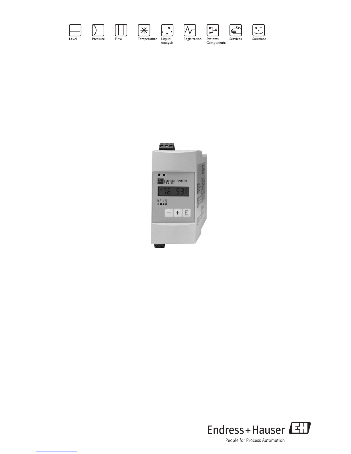
Limit alarm switch
Alarm switch and power supply for monitoring current or voltage
signals
Application
• Plant and machine construction
• Panel builders
• Process monitoring
• Process control
Your benefits
• 2 relays for set point monitoring (with SPDT contacts)
• Loop power supply for connected sensors
• LC display for alarm set points and bar graph
• Compact housing
• Front end setup using 3 push buttons
Page 2
RTA421
2 Endress+Hauser
Function and system design
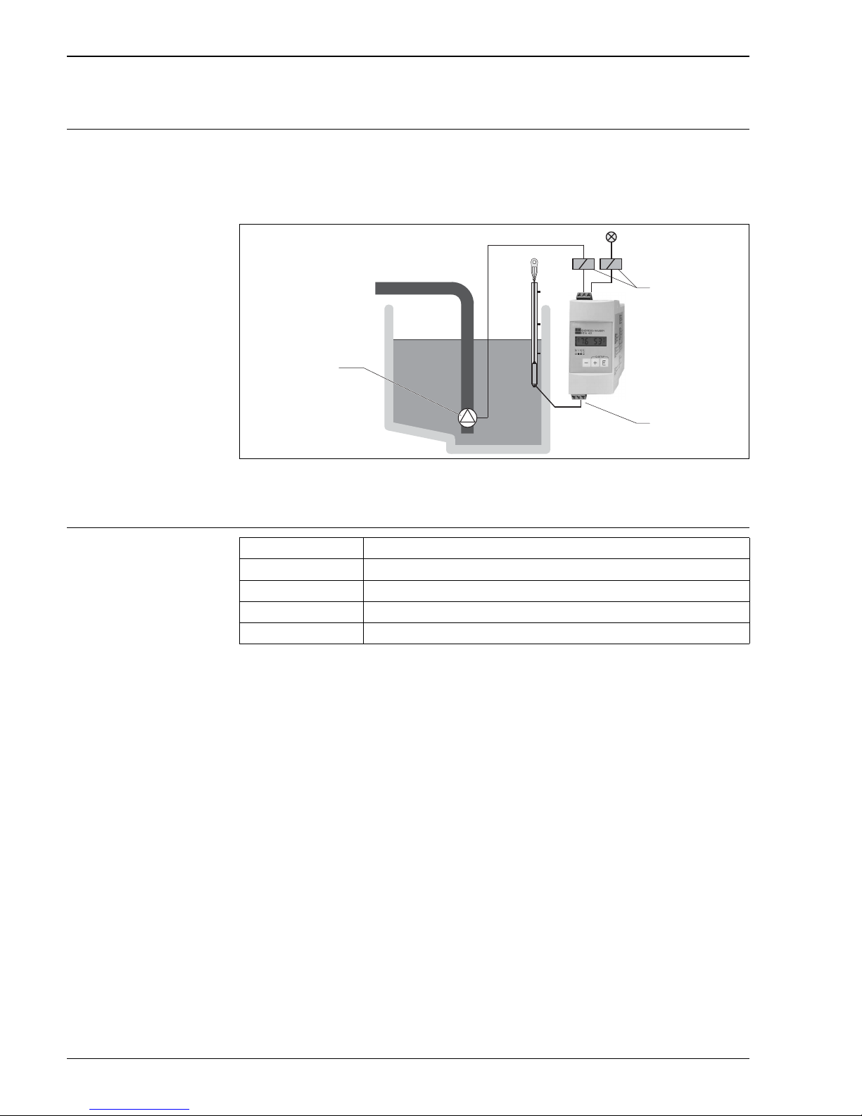
Measuring system The RTA421 contactor monitors industrial processes for safe operation. The unit analyses current (0/4...20
mA) and voltage signals (0/2...10 V) and switches two independent output relays if the values either exceed
or undercut the preset alarm set points.
Applications include pump control in the waste water industry, level measurement in silos can be economically
achieved.
a0016740
1Pump
2 Signal input with loop power supply
3Relays
Alarm set point function
1
2
3
Mode Minimum, Maximum
Switch threshold 00 to 99%
Hysteresis 01to 99%
Time delay 00 to 99 s
Reaction time 0.4 s
Page 3

RTA421
Endress+Hauser 3
Input
Number 1
Measured variable Current and voltage
Measuring range Voltage
0/2...10 V, max. voltage 50 V
Ri: 1 MΩ
Current
0/4...20 mA; max. current 150 mA
Ri: 5 Ω
Resolution Voltage
41 mV, 8 Bit
Current
83 μA, 8 Bit
Overrange 10 %
Integration time 4/s
Output
Output signal Loop power supply
Relays
Output signal Terminal 81: 24 V ±20%, 30 mA
Number 1
Galvanic isolation Between power supply and relay outputs
Output signal Binary, switches when alarm set point is reached
Number 2
Contact type SPDT potential free contact per relay
Contact load ≤ 250 VAC, 8(2) A / 30 VDC, 5(2) A
Page 4
RTA421
4 Endress+Hauser
Power supply
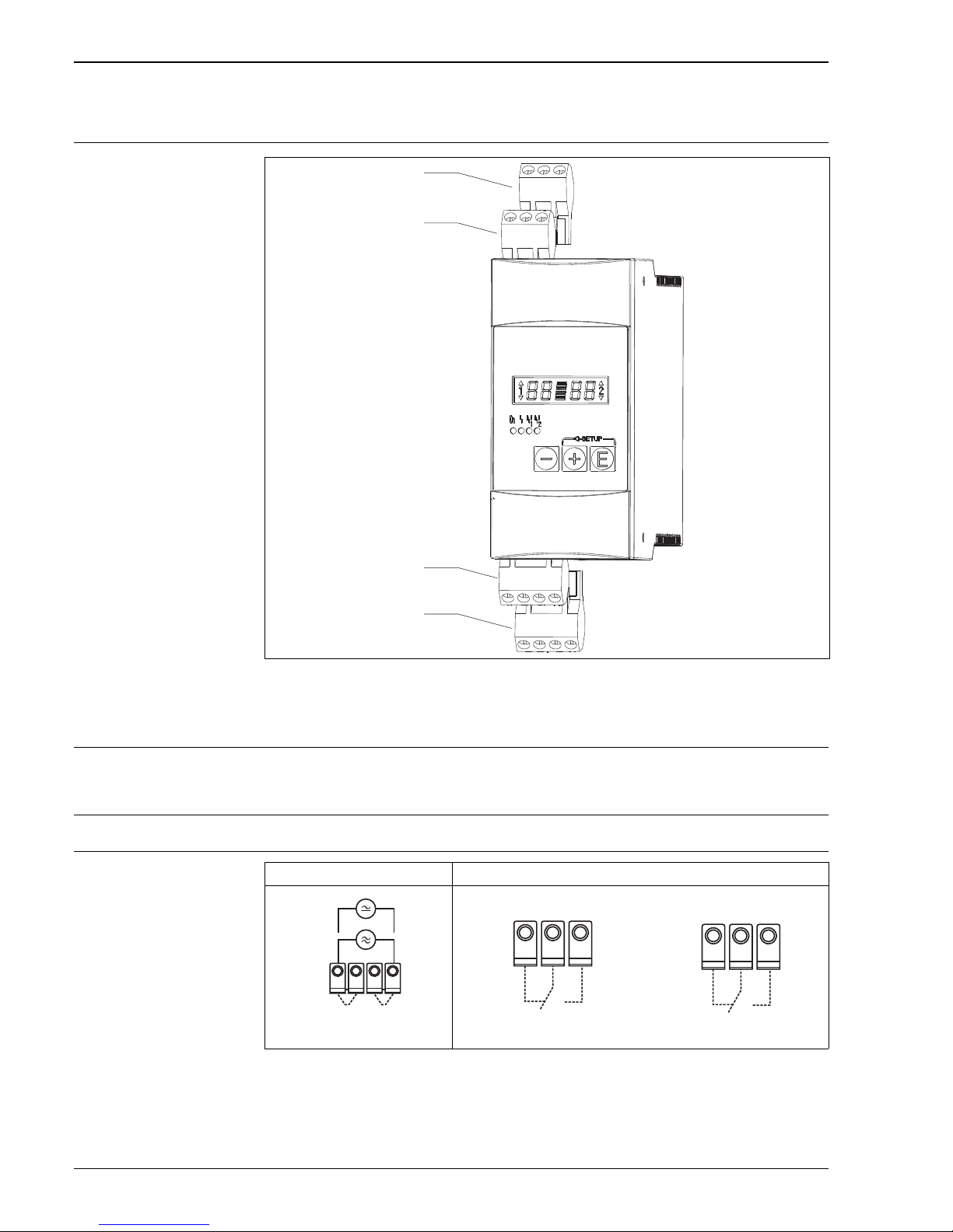
Terminal assignment
a0016729
1Relay 2
2Relay 1
3 Analog input with loop power supply
4 Power supply (20...250 V DC/AC, 196...250 V AC, 98...128 V AC)
Supply voltage 196...250 VAC, 50/60 Hz
98...126 VAC, 50/60 Hz
20...250 VDC/AC, 50/60 Hz
Power consumption Max. 9 VA
Electrical connection
41 42 43
51 52 53
L/L+ N/L-
11 15 16 81
1
2
3
4
Power supply Relays (internal circuit)
Relay 1 Relay 2
Contact condition shown in alarm or power off state
L/L+ N/L-
41
42
43
51
52
53
Page 5
RTA421
Endress+Hauser 5
Terminals Keyed, plug on screw terminals, core sizes flexible to 2.5 mm2 (13 AWG)
Fuse 315 mA, slow blow
Input current limit I
max
/ In < 15
Overvoltage protection As per IEC 61010-1
Overvoltage category II, Installation area excessive current system
≤ 10 A
Performance characteristics
Maximum measured error Voltage / current
Accuracy: 1% FSD
Influence of ambient
temperature
Voltage / current
Temperature drift: 0.02% / K (0.011% / °F) of ambient temperature
Installation
Orientation no restrictions
Environment
Ambient temperature range -20 °C…+70 °C (-4…+158 °F)
Storage temperature -20 °C…+70 °C (-4…+158 °F)
Climate class As per IEC 60 654-1 Class B3
Degree of protection IP20
Altitude Up to 2000 m (6560 ft.) above sea level according to IEC 61010-1 (EN 61010-1), CSA 1010.1-92
Electromagnetic compatibility As per IEC 61326, Class A (industrial environment)
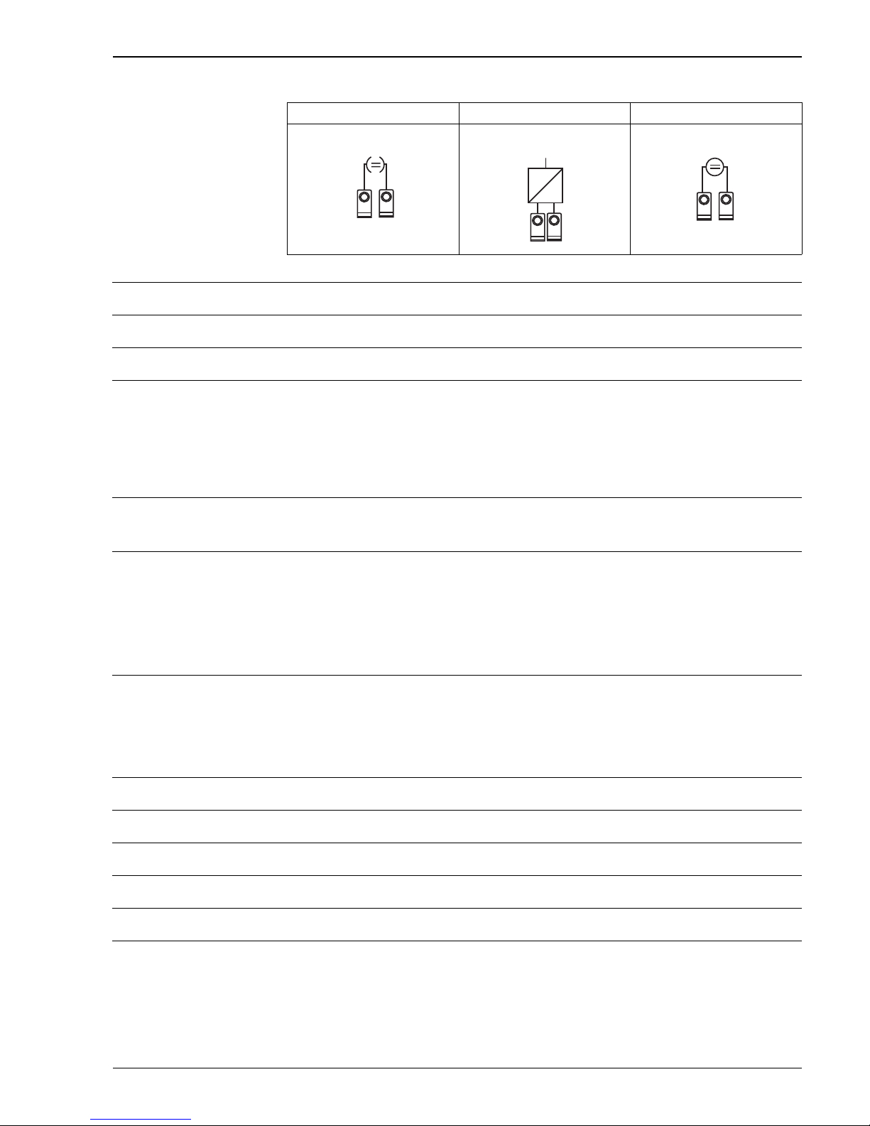
Current input Current input with loop power supply Voltage input
0/4…20 mA 4…20 mA 0/2…10 V DC
+
-
11
16
16
Y
I
81
+
-
+
-
11
15
Page 6
RTA421
6 Endress+Hauser
Mechanical construction
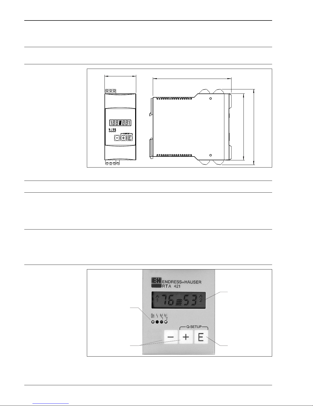
Design, dimensions Housing for top hat DIN rail mounting to IEC 60715 TH35
H: 110 mm (4.33 in), W: 45 mm (1.77 in), D: 112 mm (4.41 in)
Dimensions
a0016637
Weight approximately 150 g (0.33 lb.)
Materials Housing: Plastic PC/ABS, UL 94V0
Operability
Operating concept Quick Set
The unit is fitted with a quick set up menu so that if the set points are to be frequently changed this feature can
be started by operating the “+” and “E” push buttons. This means that the set points SP1 and SP2 can be easily
changed even during operation without opening the setting up menu.
If required a 2 digit security code is available in order to stop any changes being made to the alarm set points.
Local operation
a0016739
1 LED´s: Operational display, fault display, condition display set point relays
2 Selection keys
3Enter key
4 4 digit LC display with alarm markings and bargraph
95 (3.74)
107.8 (4.24)
112 (4.41)
45 (1.77)
mm (in)
1
2
3
4
Page 7

RTA421
Endress+Hauser 7
Both set points are simultaneously visible in the display. The ten segment bargraph additionally displays the
percentage value of the connected signal. The actual percentage measured value in the measurement circuit
can be displayed by operating either the “+” or “-” push button.
Display
LED:
Operation, 1 x green
Fault condition, 1 x red
Alarm set point, 2 x yellow
LC display:
Numeric display: 4 x 7 segments
Alarm set point condition: 2 x channel number, 4 x 1 segment
Bargraph: 10 x 1 segment
Display range
2 x 0 to 99%
Operation
3 key operation (-/+/E)
Certificates and approvals
CE mark Guidelines 89/336/EWG and 73/23/EWG
Ordering information
Detailed ordering information is available from the following sources:
• In the Product Configurator on the Endress+Hauser website: www.endress.com É Select
country É Instruments É Select device É Product page function: Configure this product
• From your Endress+Hauser Sales Center: www.endress.com/worldwide
!
Note!
Product Configurator - the tool for individual product configuration
• Up-to-the-minute configuration data
• Depending on the device: Direct input of measuring point-specific information such as measuring range
or operating language
• Automatic verification of exclusion criteria
• Automatic creation of the order code and its breakdown in PDF or Excel output format
• Ability to order directly in the Endress+Hauser Online Shop
Accessories
Field housing IP66 protective housing for field mounting
Order no. 51002468
Documentation
Standard documentation Operating instructions BA00101R/09/
Page 8

Instruments International
Endress+Hauser
Instruments International AG
Kaegenstrasse 2
4153 Reinach
Switzerland
Tel.+41 61 715 81 00
Fax+41 61 715 25 00
www.endress.com
[email protected]
TI00074R/09/EN/02.12
71196717
FM9
 Loading...