

Page 1

Products Solutions Services
Brief Operating Instructions
RIA16
Field indicator
These Instructions are Brief Operating Instructions; they do not
replace the Operating Instructions included in the scope of
supply.
Detailed information can be found in the Operating
Instructions and the additional documentation.
Available for all device versions via:
• Internet: www.endress.com/deviceviewer
• Smart phone/tablet: Endress+Hauser Operations App
KA00279R/09/A2/04.17
71355978
Page 2

RIA16
2 Endress+Hauser
Order code:
Ext. ord. cd.:
Ser. no.:
www.endress.com/deviceviewer
Endress+Hauser
Operations App
XXXXXXXXXXXX
XXXXX-XXXXXX
XXX.XXXX.XX
Serial number
1.
3.
2.
A0023555
Page 3

RIA16
Endress+Hauser 3
RIA16
Field indicator
Kurzanleitung ......................................................................... 4
Brief Operating Instructions .......................................................... 20
Page 4

Inhaltsverzeichnis RIA16
4 Endress+Hauser
Inhaltsverzeichnis
1 Hinweise zum Dokument ......................................................... 4
1.1 Darstellungskonventionen ................................................................4
1.2 Eingetragene Marken ................................................................... 6
2 Sicherheitshinweise .............................................................. 6
2.1 Anforderungen an das Personal ............................................................6
2.2 Bestimmungsgemäße Verwendung ......................................................... 6
2.3 Arbeitssicherheit ...................................................................... 7
2.4 Betriebssicherheit ...................................................................... 7
2.5 Produktsicherheit ...................................................................... 7
3 Identifizierung .................................................................... 7
3.1 Typenschild .......................................................................... 7
3.2 Lieferumfang ......................................................................... 8
3.3 Zertifikate und Zulassungen .............................................................. 8
4 Montage .......................................................................... 9
4.1 Warenannahme, Transport, Lagerung ....................................................... 9
4.2 Montagebedingungen ................................................................... 9
4.3 Montageanleitung .................................................................... 10
4.4 Montagekontrolle ..................................................................... 11
5 Verdrahtung ..................................................................... 12
5.1 Verdrahtung auf einen Blick ............................................................. 13
5.2 Elektrischer Anschluss ................................................................. 14
5.3 Schutzart ........................................................................... 14
5.4 Anschlusskontrolle .................................................................... 14
6 Bedienung des Feldanzeigers .................................................... 14
6.1 Anzeige und Bedienelemente ............................................................ 14
6.2 Parametrierung über Bedientasten ........................................................ 15
6.3 Bedienmatrix ........................................................................ 17
6.4 Konfiguration über Schnittstelle & PC-Konfigurationssoftware FieldCare Device Setup ................... 18
6.5 Gerätekonfiguration ................................................................... 19
1 Hinweise zum Dokument
1.1 Darstellungskonventionen
1.1.1 Warnhinweissymbole
Symbol Bedeutung
GEFAHR
GEFAHR!
Dieser Hinweis macht auf eine gefährliche Situation aufmerksam, die, wenn sie nicht
vermieden wird, zu Tod oder schwerer Körperverletzung führen wird.
WARNUNG
WARNUNG!
Dieser Hinweis macht auf eine gefährliche Situation aufmerksam, die, wenn sie nicht
vermieden wird, zu Tod oder schwerer Körperverletzung führen kann.
Page 5

RIA16 Hinweise zum Dokument
Endress+Hauser 5
Symbol Bedeutung
VORSICHT
VORSICHT!
Dieser Hinweis macht auf eine gefährliche Situation aufmerksam, die, wenn sie nicht
vermieden wird, zu leichter oder mittelschwerer Körperverletzung führen kann.
HINWEIS
HINWEIS!
Dieser Hinweis enthält Informationen zu Vorgehensweisen und weiterführenden
Sachverhalten, die keine Körperverletzung nach sich ziehen.
1.1.2 Elektrische Symbole
Symbol Bedeutung Symbol Bedeutung
Gleichstrom Wechselstrom
Gleich- und Wechselstrom Erdanschluss
Eine geerdete Klemme, die vom
Gesichtspunkt des Benutzers über ein
Erdungssystem geerdet ist.
Symbol Bedeutung
Schutzleiteranschluss
Eine Klemme, die geerdet werden muss, bevor andere Anschlüsse hergestellt werden dürfen.
Äquipotenzialanschluss
Ein Anschluss, der mit dem Erdungssystem der Anlage verbunden werden muss: Dies kann z.B. eine
Potenzialausgleichsleitung oder ein sternförmiges Erdungssystem sein, je nach nationaler bzw.
Firmenpraxis.
1.1.3 Symbole für Informationstypen
Symbol Bedeutung Symbol Bedeutung
Erlaubt
Abläufe, Prozesse oder Handlungen,
die erlaubt sind.
Zu bevorzugen
Abläufe, Prozesse oder Handlungen,
die zu bevorzugen sind.
Verboten
Abläufe, Prozesse oder Handlungen,
die verboten sind.
Tipp
Kennzeichnet zusätzliche
Informationen.
Verweis auf Dokumentation
A
Verweis auf Seite
Verweis auf Abbildung
1.
, 2., 3.… Handlungsschritte
Ergebnis eines Handlungsschritts Sichtkontrolle
Page 6

Sicherheitshinweise RIA16
6 Endress+Hauser
1.1.4 Werkzeugsymbole
Symbol Bedeutung
A0011220
Schlitzschraubendreher
A0011221
Innensechskantschlüssel
A0011222
Gabelschlüssel
A0013442
Torx Schraubendreher
1.2 Eingetragene Marken
HART
®
Eingetragene Marke der HART Communication Foundation, Austin, USA
Applicator®, FieldCare®, Field XpertTM, HistoROM
®
Eingetragene oder angemeldete Marken der Unternehmen der Endress+Hauser Gruppe
2 Sicherheitshinweise
2.1 Anforderungen an das Personal
Das Personal muss für seine Tätigkeiten folgende Bedingungen erfüllen:
‣
Ausgebildetes Fachpersonal: Verfügt über Qualifikation, die dieser Funktion und Tätigkeit
entspricht
‣
Vom Anlagenbetreiber autorisiert
‣
Mit den nationalen Vorschriften vertraut
‣
Vor Arbeitsbeginn: Anweisungen in Anleitung und Zusatzdokumentation sowie Zertifikate
(je nach Anwendung) lesen und verstehen
‣
Anweisungen und Rahmenbedingungen befolgen
2.2 Bestimmungsgemäße Verwendung
• Das Gerät ist ein konfigurierbarer Feldanzeiger mit einem Sensoreingang.
• Das Gerät ist zur Montage im Feld bestimmt.
• Für Schäden aus unsachgemäßem oder nicht bestimmungsgemäßem Gebrauch haftet der
Hersteller nicht.
• Ein gefahrloser Betrieb ist nur sichergestellt, wenn die Betriebsanleitung beachtet wird.
• Gerät nur in dem dafür vorgesehenen Temperaturbereich betreiben.
Page 7

RIA16 Identifizierung
Endress+Hauser 7
2.3 Arbeitssicherheit
Bei Arbeiten am und mit dem Gerät:
‣
Erforderliche persönliche Schutzausrüstung gemäß nationaler Vorschriften tragen.
2.4 Betriebssicherheit
Verletzungsgefahr!
‣
Das Gerät nur in technisch einwandfreiem und betriebssicherem Zustand betreiben.
‣
Der Betreiber ist für den störungsfreien Betrieb des Geräts verantwortlich.
Umgebungsanforderungen
Wenn ein Messumformergehäuse aus Kunststoff bestimmten Dampf-Luft-Gemischen
permanent ausgesetzt ist, kann das Gehäuse beschädigt werden.
‣
Bei Unklarheiten Ihre Endress+Hauser Vertriebszentrale kontaktieren.
‣
Beim Einsatz im zulassungsrelevanten Bereich: Angaben auf dem Typenschild beachten.
2.5 Produktsicherheit
Dieses Messgerät ist nach dem Stand der Technik und guter Ingenieurspraxis betriebssicher
gebaut und geprüft und hat das Werk in sicherheitstechnisch einwandfreiem Zustand
verlassen.
Es erfüllt die allgemeinen Sicherheitsanforderungen und gesetzlichen Anforderungen. Zudem
ist es konform zu den EG-Richtlinien, die in der gerätespezifischen EG-Konformitätserklärung
aufgelistet sind. Mit der Anbringung des CE-Zeichens bestätigt Endress+Hauser diesen
Sachverhalt.
3 Identifizierung
3.1 Typenschild
Das richtige Gerät?
Vergleichen Sie bitte den Bestellcode auf dem Typenschild am Gerät mit dem auf dem
Lieferschein.
Page 8

Identifizierung RIA16
8 Endress+Hauser
A0011268
1 Typenschild des Feldanzeigers (beispielhaft)
1 Bezeichnung, Bestellcode, Seriennummer und Ident-Nummer des Gerätes
2 Schutzart
3 Spannungsversorgung und Ausgangssignal
4 Umgebungstemperatur
5 Zulassungen
6 Herstellername und -adresse
3.2 Lieferumfang
Der Lieferumfang des Feldanzeigers besteht aus:
• Feldanzeiger
• Schirmklemmen (nur für Aluminiumgehäuse)
• Kurzanleitung in Papierform
• ATEX - Sicherheitshinweise für den Einsatz eines im explosionsgefährdeten Bereich
zulässigen Gerätes, optional
• Zubehör (z. B. Rohrmontagehalter), siehe Kapitel ’Zubehör’ in der Betriebsanleitung
→
BA00280R.
3.3 Zertifikate und Zulassungen
3.3.1 CE-Zeichen
Das Produkt erfüllt die Anforderungen der harmonisierten europäischen Normen. Damit
erfüllt es die gesetzlichen Vorgaben der EU-Richtlinien. Der Hersteller bestätigt die
erfolgreiche Prüfung des Produkts durch die Anbringung des CE-Zeichens.
3.3.2 EAC-Zeichen
Das Produkt erfüllt die gesetzlichen Anforderungen der anwendbaren EEU-Richtlinien. Der
Hersteller bestätigt die erfolgreiche Prüfung des Produkts mit der Anbringung des EACZeichens.
3.3.3 UL-Zulassung
UL recognized component (siehe www.ul.com/database, Suche nach Keyword "E225237")
Page 9

RIA16 Montage
Endress+Hauser 9
4 Montage
4.1 Warenannahme, Transport, Lagerung
Die zulässigen Umgebungs- und Lagerbedingungen sind einzuhalten. Genaue Spezifikationen
hierzu siehe Kapitel "Technische Daten" in der Betriebsanleitung.
4.1.1 Warenannahme
Bei der Warenannahme folgende Punkte kontrollieren:
• Sind Verpackung oder Inhalt beschädigt?
• Ist die gelieferte Ware vollständig? Vergleichen Sie den Lieferumfang mit ihren
Bestellangaben. Siehe auch Kapitel "Lieferumfang" → 8.
4.1.2 Transport und Lagerung
Folgende Punkte beachten:
• Für Lagerung und Transport ist das Gerät stoßsicher zu verpacken. Dafür bietet die
Originalverpackung optimalen Schutz.
• Die zulässige Lagerungstemperatur –40…+80 °C (–40…+176 °F); die Lagerung in den
Grenztemperaturbereichen ist zeitlich begrenzt möglich (maximal 48 Stunden).
4.2 Montagebedingungen
Der Anzeiger ist für den Einsatz im Feld konzipiert.
Die Einbaulage wird von der Ablesbarkeit des Displays bestimmt.
Arbeitstemperaturbereich:
• –40…+80 °C (–40…+176 °F)
• –20…+80 °C (–4…+176 °F) bei Verwendung des Open Collector Ausgangs
Bei einem Betrieb des Anzeigers im oberen Temperaturgrenzbereich verringert sich die
Lebensdauer des Displays.
Bei Temperaturen < –20 °C (–4 °F) kann die Anzeige träge reagieren.
Bei Temperaturen < –30 °C (–22 °F) ist die Ablesbarkeit der Anzeige nicht mehr
gewährleistet.
Page 10
Montage RIA16
10 Endress+Hauser
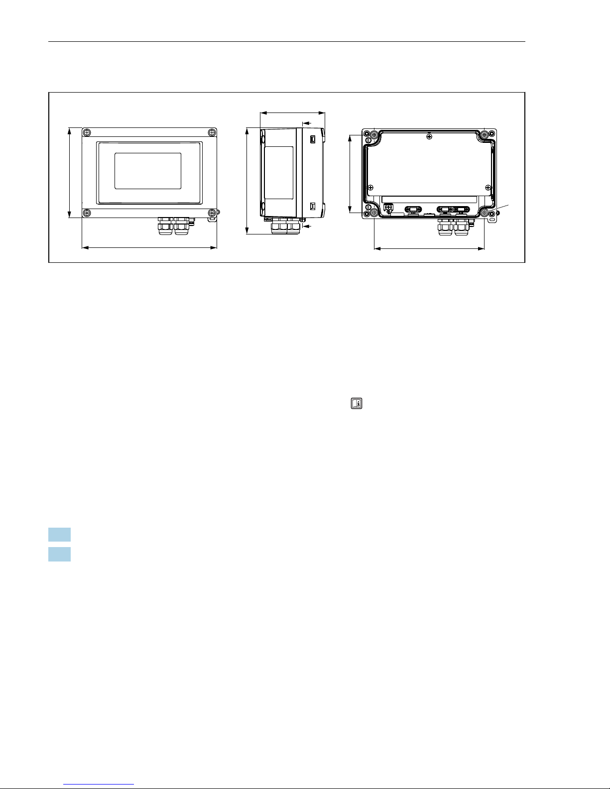
4.2.1 Abmessungen
133 (5.24)
199 (7.83)
96 (3.78)
158 (6.22)
1
115 (4.53)
163 (6.42)
A
A
A-A
A0011162
2 Abmessungen des Feldanzeigers; Angaben in mm (in)
1 Bohrung zur Montage direkt an der Wand oder auf optionale Montageplatte mit 4 Schrauben ⌀ 5 mm
(0,2 in)
4.2.2 Montageort
Informationen über Bedingungen, die am Montageort vorliegen müssen, um das Gerät
bestimmungsgemäß zu montieren, wie Umgebungstemperatur, Schutzart, Klimaklasse etc.,
siehe Kapitel "Technische Daten" in der Betriebsanleitung → BA00280R.
4.3 Montageanleitung
Der Feldanzeiger kann entweder direkt an der Wand befestigt oder mittels optionalem
Montagekit an Rohr (→ 10) oder Wand montiert werden.
4.3.1 Direkte Wandmontage
Vorgehen zur direkten Wandmontage des Anzeigers
1. 4 Löcher bohren (siehe Abmessungen, → 2, 10)
2. Gerät an der Wand mit 4 Schrauben 5 mm (0,2 in) anbringen.
4.3.2 Rohrmontage
Der Montagehalter ist geeignet für Rohre mit einem Durchmesser von 25…125 mm (1…5 in).
Das Montageset besteht aus Montageplatte (Pos. 1), 2 Metallbändern (Pos. 2) und 4
Schrauben (Pos. 3), → 3, 11.
Vorgehen zur Rohrmontage des Anzeigers
Page 11

RIA16 Montage
Endress+Hauser 11
1
2
1. 2.
A0011269
3 Montage vorbereiten
3mm
3.
4.
3
3
A0011270
4 Anzeiger auf der Montageplatte anbringen
4.4 Montagekontrolle
Nach der Montage folgende Kontrollen durchführen:
Gerätezustand und -spezifikationen Hinweise
Ist das Messgerät beschädigt? Sichtkontrolle
Ist die Dichtung unbeschädigt? Sichtkontrolle
Ist das Gerät fest an die Wand oder auf die Montageplatte geschraubt? -
Page 12

Verdrahtung RIA16
12 Endress+Hauser
Gerätezustand und -spezifikationen Hinweise
Ist der Gehäusedeckel fest montiert? -
Entspricht das Gerät den Messstellenspezifikationen, wie Umgebungstemperatur,
Messbereich, usw.?
Siehe Kapitel "Technische
Daten".
5 Verdrahtung
Für den Anschluss von Ex-zertifizierten Geräten die entsprechenden Hinweise und
Anschlussbilder in den spezifischen Ex-Zusatzdokumentationen zu dieser Betriebsanleitung
beachten. Bei Fragen steht Ihnen Ihre E+H-Vertretung gerne zur Verfügung.
Zunächst das Gehäuse des Feldanzeigers öffnen.
A0011271
5 Gehäuse des Feldanzeigers öffnen
A0014935
6 Einbau Schirmklemmen (nur für Aluminiumgehäuse)
Page 13

RIA16 Verdrahtung
Endress+Hauser 13
5.1 Verdrahtung auf einen Blick
5.1.1 Klemmenbelegung
+
+
I
Y
-
-
+
I
Y
-
3
2
+
-
OC
+
-
1a1b
+
-
2
3
+
-
1a
1b
+
+
I
Y
-
-
+
-
1a
1b
Messumformerspeisung
Klemme 2 und 3
Open Collector
aktiv
passiv
Messumformerspeisung
A0011165-DE
7 Klemmenbelegung des Feldanzeigers
Klemme Klemmenbelegung Ein- und Ausgang
+ Messsignal (+) 4…20 mA Signaleingang
- Messsignal (-) 4…20 mA Signaleingang
1 Anschlussklemme für weitere Instrumentierung Stützklemme
2 Digitaler Grenzwertschalter (Kollektor) Schaltausgang
3 Digitaler Grenzwertschalter (Emitter) Schaltausgang
Page 14

Bedienung des Feldanzeigers RIA16
14 Endress+Hauser
5.2 Elektrischer Anschluss
Sowohl die Klemmenbelegung, als auch die Anschlusswerte des Feldanzeigers entsprechen
denen der Ex-Ausführung. Das Gerät ist nur zum Betrieb in einem 4…20 mA Messstromkreis
vorgesehen. Entlang der Stromkreise (innerhalb und außerhalb des explosionsgefährdeten
Bereichs) muss Potenzialausgleich bestehen.
5.3 Schutzart
Die Geräte erfüllen alle Anforderungen gemäß IP67. Um nach erfolgter Montage oder nach
einem Service-Fall diese zu gewährleisten, müssen folgende Punkte zwingend beachtet
werden:
• Die Gehäusedichtung muss sauber und unbeschädigt in die Dichtungsnut eingelegt sein.
Gegebenenfalls ist die Dichtung zu reinigen, zu trockenen oder zu ersetzen.
• Die für den Anschluss verwendeten Kabel müssen den spezifizierten Außendurchmesser
aufweisen (z.B. M20 x 1,5, Kabeldurchmesser 8…12 mm (0,3…0,47 in)). Montieren Sie das
Messgerät möglichst so, dass die Kabeleinführungen nach unten gerichtet sind.
• Nicht benutzte Kabeleinführungen sind durch einen Blindstopfen ersetzen.
• Die verwendete Schutztülle darf nicht aus der Kabeleinführung entfernt werden.
• Der Gehäusedeckel und die Kabeleinführung müssen fest angezogen sein.
5.4 Anschlusskontrolle
Nach der elektrischen Installation folgende Kontrollen durchführen:
Gerätezustand und -spezifikationen Hinweis
Sind Gerät oder Kabel beschädigt? Sichtkontrolle
Elektrischer Anschluss Hinweis
Ist die Kabeltypenführung einwandfrei getrennt - Ohne Schleifen und Überkreuzungen -
Sind die Kabel zugentlastet montiert? -
Ist die Klemmenbelegung richtig? Anschlussschema vom Klemmenblock vergleichen. → 13
Sind alle Schrauben der Anschlussklemmen fest? Sichtkontrolle
Ist die Kabelverschraubung dicht? Sichtkontrolle
Ist der Gehäusedeckel fest angezogen? Sichtkontrolle
6 Bedienung des Feldanzeigers
6.1 Anzeige und Bedienelemente
Anzeigedarstellung
Page 15

RIA16 Bedienung des Feldanzeigers
Endress+Hauser 15
1
2
6
5
4
3
1b
A0011163
8 LC-Anzeige des Feldanzeigers
1 Bargraphanzeige 3 14-Segment Anzeige für Einheiten und
Meldungen
1a Marke für Messbereichsunterschreitung 4 Symbol ’Programmierung gesperrt’
1b Marke für Messbereichsüberschreitung 5 Einheit ’%’
2 Messwertanzeige
Ziffernhöhe 26 mm (1,02 in)
6 Warnsymbol ’Störung’
6.2 Parametrierung über Bedientasten
Die Parametrierung muss außerhalb des explosionsgefährdeten Bereichs erfolgen.
A0011261
9 Bedientasten des Feldanzeigers ("-", "+", "E")
Die Bedientasten sind bei geöffnetem Gehäusedeckel zugänglich.
Während der Parametrierung muss das Display mit der Elektronikeinheit verbunden
bleiben.
6.2.1 Navigation
Die Bedienfelder sind in 2 Ebenen eingeteilt.
Menü: In der Ebene Menü können unterschiedliche Menüpunkte gewählt werden. Die
einzelnen Menüpunkte dienen als Zusammenfassung von zusammengehörigen
Bedienfunktionen.
Page 16

Bedienung des Feldanzeigers RIA16
16 Endress+Hauser
Bedienfunktion: Eine Bedienfunktion ist als Zusammenfassung von Bedienparametern
anzusehen. In den Bedienfunktionen erfolgt die eigentliche Bedienung bzw. Parametrierung
des Gerätes.
Bedientasten:
Eingabetaste ’E’: Einstieg in das Programmiermenü, wenn die E Taste länger als 3 Sekunden
gedrückt wird.
• Anwählen von Bedienfunktionen.
• Übernehmen von Werten.
• Wenn die E Taste länger als 3 Sekunden gedrückt wird erfolgt ein direkter Sprung zur Home
Position. Vorher erfolgt eine Abfrage, ob die bis dahin eingegebenen Daten gespeichert
werden sollen.
• Abspeichern von eingegebenen Daten.
Auswahltasten ’+/-’:
• Auswählen der Menüs.
• Einstellen von Parametern und Zahlenwerten.
• Nach Auswahl der Bedienfunktion wird durch Drücken der Tasten + oder - der Wert
eingegeben oder die Einstellung verändert.
Bei langanhaltendem Drücken der Tasten erfolgt eine Zahlenänderung mit zunehmender
Geschwindigkeit.
Bei den Bedienpositionen "Programmname" und "Programmversion" wird beim Drücken
der Tasten + oder - die Anzeige horizontal gescrollt, da diese Positionen (7stellig) nicht
vollständig in der 14-Segment-Anzeige dargestellt werden kann.
6.2.2 Programmieren in der Bedienmatrix
E
E
E
+
_
+
_
+
_
E
E
> 3 s
_
+
E
> 3 s
E E E
7.
6.
5.
1.
2.
3.
4.
Menü
Bedienfunktion
A0011262-DE
10 Programmierung des Feldanzeigers
Page 17

RIA16 Bedienung des Feldanzeigers
Endress+Hauser 17
1. Einstieg in die Bedienmatrix
2. Menü mit "+" oder "-" Taste auswählen
3. Bedienfunktion auswählen
4. Parameter im Editiermodus eingeben (Daten mit "+" oder "-" eingeben/auswählen und
mit "E" übernehmen)
5. Direkt zur Home-Position springen. Vorher erfolgt eine Abfrage, ob die bis dahin
eingegebenen Daten gespeichert werden sollen.
6. Menü mit "+/-" verlassen. Es erfolgt eine Abfrage, ob die eingegebenen Daten
gespeichert werden sollen.
7. Abfrage ob Daten gespeichert werden sollen bestätigen. Ja/Nein mit "+" oder "-" Taste
auswählen und mit "E" bestätigen.
6.3 Bedienmatrix
Menü Bedienfunktion Bedienfunktion Bedienfunktion
Parameter Default /
Auswahl
Parameter Default /
Auswahl
Parameter Default /
Auswahl
Analogeingang
INPUT
Kennlinie
CURV
Signaldämpfung
DAMP
Dezimalpunkt Messwert
DI DP
Linear LINAR 0…99 s 0 99,999 3 DEC
Quadratisch SQRT 999,99 2 DEC
9 999,9 1 DEC
99 999 0 DEC
Skalierung Messwert 4 mA
DI LO
Skalierung Messwert 20 mA
DI HI
Messwert Offset
OFFST
–9 999…
99 999
0,0 –9 999…
99 999
100,0 –9 999…
99 999
0,0
Anzeige
DISPL
Dimension
DIM
Dimension
1)
DTEXT
keine
%
beliebig
NO
%
TEXT
XXXXX
Limit
LIMIT
Betriebsart
MODE
Schaltschwelle
SETP
aus OFF –9 999…
99 999
0,0
Min.Sicherh.
mit Alarm
MIN
Max.Sicherh.
mit Alarm
MAX
Alarm ALARM
Page 18

Bedienung des Feldanzeigers RIA16
18 Endress+Hauser
Menü Bedienfunktion Bedienfunktion Bedienfunktion
Parameter Default /
Auswahl
Parameter Default /
Auswahl
Parameter Default /
Auswahl
Hysterese
HYST
Ansprechverzögerung
DELY
–9 999…
99 999
0,0 0…99 s 0,0
Betriebsparameter
PARAM
Benutzercode
CODE
Programmname
PNAME
Firmware-Version
FWVER
0…9 999 0
NAMUR
NAMUR
NAMUR 3,6
2)
N_360
NAMUR 3,80
2)
N_380
Standard dEF 0 bis NAMUR
20,5
3,60 NAMUR 3,6
bis NAMUR
20,5
3,80
Eingabe Edit
NAMUR 20,5
2)
N2050
NAMUR 21,0
2)
N2100
Test
TEST
NAMUR 3,80
bis NAMUR
21,0
20,5 20,5 bis
25 mA
21,0 aus OFF
Open Collect. OUT
Display DISP
Service
SERV
Servicecode
SCODE
Parameter rücksetzen
3)
PRSET
---- ja YES
nein NO
1) Nur, wenn DIM = TEXT
2) Nur, wenn NAMUR = Edit
3) nur für Service-Mitarbeiter durchführbar
6.4 Konfiguration über Schnittstelle & PC-Konfigurationssoftware
FieldCare Device Setup
L
WARNUNG
Verlust des Explosionsschutzes bei geöffnetem Gehäuse
‣
Die Parametrierung muss außerhalb des explosionsgefährdeten Bereichs erfolgen.
Während der Parametrierung mit FieldCare kann das Gerät undefinierte Zustände annehmen!
Dies kann das undefinierte Schalten von Ausgängen und Relais zur Folge haben.
Für die Konfiguration des Gerätes über die Software FieldCare Device Setup verbinden Sie das
Gerät mit Ihrem PC. Hierzu benötigen Sie einen speziellen Schnittstellenadapter, die
Commubox FXA291.
Der vierpolige Stecker des Schnittstellenkabels ist in die entsprechende Buchse im Gerät
einzustecken, der USB-Stecker ist am PC in einen freien USB-Steckplatz einzustecken.
Page 19

RIA16 Bedienung des Feldanzeigers
Endress+Hauser 19
6.4.1 Verbindungsaufbau
Beim Anschluss des Gerätes wird der Geräte-DTM nicht automatisch in FieldCare geladen,
d.h. das Gerät muss manuell hinzugefügt werden.
Beim RIA14/16 ist keine Online-Parametrierung möglich.
• Fügen Sie zunächst einem leeren Projekt den Kommunikations-DTM "PCP (Readwin)
TXU10 / FXA291" hinzu.
• In den Einstellungen des Comm DTM die Baudrate auf 2400 Baud und den verwendeten
COM-Port einstellen.
• In das Projekt über die Funktion "Gerät hinzufügen..." den Geräte DTM "RIA14/16 / Vx.xx.xx"
einfügen.
• Die weitere Parametrierung des Gerätes führen Sie dann anhand dieser GeräteBetriebsanleitung durch. Das gesamte Setup-Menü, also alle in dieser Betriebsanleitung
aufgeführten Parameter finden Sie ebenfalls in FieldCare Device Setup vor.
USB
PC Konfigurationssoftware
Konfigurations-Kit USB-Box
A0011272-DE
11 Konfiguration des Feldanzeigers über Schnittstellenadapter
Grundsätzlich ist ein Überschreiben von Parametern durch die PC Software FieldCare und
den entsprechenden Geräte DTM auch bei aktivem Zugriffsschutz möglich. Soll der
Zugriffsschutz anhand eines Codes auch auf die Software ausgeweitet werden, ist diese
Funktionalität im erweiterten Gerätesetup zu aktivieren.
6.5 Gerätekonfiguration
Detaillierte Informationen zur Gerätekonfiguration finden Sie in der Betriebsanleitung.
Page 20

Table of contents RIA16
20 Endress+Hauser
Table of contents
1 Document information .......................................................... 20
1.1 Document conventions ................................................................. 20
1.2 Registered trademarks ................................................................. 22
2 Safety instructions ............................................................... 22
2.1 Requirements for the personnel ........................................................... 22
2.2 Designated use ....................................................................... 22
2.3 Workplace safety ..................................................................... 23
2.4 Operational safety .....................................................................23
2.5 Product safety ........................................................................ 23
3 Identification .................................................................... 23
3.1 Nameplate .......................................................................... 23
3.2 Scope of delivery ...................................................................... 24
3.3 Certificates and approvals ............................................................... 24
4 Installation ...................................................................... 25
4.1 Incoming acceptance, transport, storage .................................................... 25
4.2 Installation conditions .................................................................. 25
4.3 Mounting instructions .................................................................. 26
4.4 Post-installation check ................................................................. 27
5 Wiring ........................................................................... 28
5.1 Quick wiring guide .................................................................... 29
5.2 Electrical connection ................................................................... 30
5.3 Degree of protection ................................................................... 30
5.4 Post-connection check ..................................................................30
6 Operating the field indicator ..................................................... 30
6.1 Display and operating elements ........................................................... 30
6.2 Configuration via operating keys .......................................................... 31
6.3 Operating matrix ..................................................................... 33
6.4 Configuration via interface & FieldCare Device Setup PC configuration software ....................... 34
1 Document information
1.1 Document conventions
1.1.1 Safety symbols
Symbol Meaning
DANGER
DANGER!
This symbol alerts you to a dangerous situation. Failure to avoid this situation will result in
serious or fatal injury.
WARNING
WARNING!
This symbol alerts you to a dangerous situation. Failure to avoid this situation can result in
serious or fatal injury.
Page 21

RIA16 Document information
Endress+Hauser 21
Symbol Meaning
CAUTION
CAUTION!
This symbol alerts you to a dangerous situation. Failure to avoid this situation can result in
minor or medium injury.
NOTICE
NOTE!
This symbol contains information on procedures and other facts which do not result in
personal injury.
1.1.2 Electrical symbols
Symbol Meaning Symbol Meaning
Direct current Alternating current
Direct current and alternating current Ground connection
A grounded terminal which, as far as
the operator is concerned, is grounded
via a grounding system.
Symbol Meaning
Protective ground connection
A terminal which must be connected to ground prior to establishing any other connections.
Equipotential connection
A connection that has to be connected to the plant grounding system: This may be a potential
equalization line or a star grounding system depending on national or company codes of practice.
1.1.3 Symbols for certain types of information
Symbol Meaning Symbol Meaning
Permitted
Procedures, processes or actions that
are permitted.
Preferred
Procedures, processes or actions that
are preferred.
Forbidden
Procedures, processes or actions that
are forbidden.
Tip
Indicates additional information.
Reference to documentation
A
Reference to page
Reference to graphic
1.
, 2., 3.… Series of steps
Result of a step Visual inspection
Page 22

Safety instructions RIA16
22 Endress+Hauser
1.1.4 Tool symbols
Symbol Meaning
A0011220
Flat blade screwdriver
A0011221
Allen key
A0011222
Open-ended wrench
A0013442
Torx screwdriver
1.2 Registered trademarks
HART
®
Registered trademark of the HART Communication Foundation, Austin, U.S.A.
Applicator®, FieldCare®, Field XpertTM, HistoROM
®
Registered trademarks or trademarks of companys of the Endress+Hauser group
2 Safety instructions
2.1 Requirements for the personnel
The personnel must fulfill the following requirements for its tasks:
‣
Trained, qualified specialists must have a relevant qualification for this specific function
and task
‣
Are authorized by the plant owner/operator
‣
Are familiar with federal/national regulations
‣
Before beginning work, the specialist staff must have read and understood the instructions
in the Operating Instructions and supplementary documentation as well as in the
certificates (depending on the application)
‣
Following instructions and basic conditions
2.2 Designated use
• The device is a configurable field indicator with one sensor input.
• The device is designed for installation in the field.
• The manufacturer does not accept liability for damage caused by improper or nondesignated use.
• Safe operation is only guaranteed if the Operating Instructions are observed and adhered to.
• Only operate the device in the permitted temperature range.
Page 23

RIA16 Identification
Endress+Hauser 23
2.3 Workplace safety
For work on and with the device:
‣
Wear the required personal protective equipment according to federal/national
regulations.
2.4 Operational safety
Risk of injury.
‣
Operate the device in proper technical condition and fail-safe condition only.
‣
The operator is responsible for interference-free operation of the device.
Environmental requirements
If a plastic transmitter housing is permanently exposed to certain steam and air mixtures, this
can damage the housing.
‣
If you are unsure, please contact your Endress+Hauser Sales Center for clarification.
‣
If used in an approval-related area, observe the information on the nameplate.
2.5 Product safety
This measuring device is designed in accordance with good engineering practice to meet stateof-the-art safety requirements, has been tested, and left the factory in a condition in which it
is safe to operate.
It meets general safety standards and legal requirements. It also complies with the EC
directives listed in the device-specific EC Declaration of Conformity. Endress+Hauser confirms
this by affixing the CE mark to the device.
3 Identification
3.1 Nameplate
The right device?
Compare the order code on the nameplate of the device to that on the delivery papers.
Page 24

Identification RIA16
24 Endress+Hauser
A0011268
1 Nameplate of the field indicator (example)
1 Designation, order code and serial number of the device
2 Degree of protection
3 Power supply and output signal
4 Ambient temperature
5 Approvals
6 Manufacturer name and address
3.2 Scope of delivery
The scope of delivery of the field indicator comprises:
• Field indicator
• Cable shield grounding clamps (only for aluminum housing)
• Brief operating instructions as hardcopy
• ATEX Safety Instructions for deploying a device permitted for use in hazardous areas,
optional
• Accessories (eg. pipe mounting kit), see chapter ’Accessories’ in the Operating instructions
→
BA00280R.
3.3 Certificates and approvals
3.3.1 CE mark
The measuring system meets the legal requirements of the applicable EC guidelines. These are
listed in the corresponding EC Declaration of Conformity together with the standards applied.
The manufacturer confirms successful testing of the device by affixing to it the CE mark.
3.3.2 EAC mark
The product meets the legal requirements of the EEU guidelines. The manufacturer confirms
the successful testing of the product by affixing the EAC mark.
3.3.3 UL approval
UL recognized component (see www.ul.com/database, search for Keyword "E225237")
Page 25

RIA16 Installation
Endress+Hauser 25
4 Installation
4.1 Incoming acceptance, transport, storage
The permitted ambient and storage conditions must be observed. The precise specifications
can be found in Section "Technical data" in the Operating Instructions.
4.1.1 Incoming acceptance
On receipt of the goods, check the following points:
• Are the packaging or contents damaged?
• Is anything missing from the delivery? Compare the scope of delivery with the information
you specified in the order. See also section "Scope of delivery" → 24.
4.1.2 Transportation and storage
Note the following points:
• Pack the device so that is protected against impact for storage and transportation. The
original packaging provides optimum protection.
• The permitted storage temperature range is –40 to +80 °C (–40 to +176 °F); it is possible to
store the device in the limit temperature ranges for a limited period (maximum 48 hours)..
4.2 Installation conditions
The process indicator is designed to be used in the field.
The orientation is determined by the readability of the display.
Operational temperature range:
• –40 to +80 °C (–40 to +176 °F)
• –20 to +80 °C (–4 to +176 °F) when the open collector output is used
If the device is operated in the upper temperature limit range, this reduces the operating
life of the indicator.
The display may react slowly at temperatures < –20 °C (–4 °F).
Readability of the display cannot be guaranteed at temperatures < –30 °C (–22 °F).
Page 26

Installation RIA16
26 Endress+Hauser
4.2.1 Dimensions
133 (5.24)
199 (7.83)
96 (3.78)
158 (6.22)
1
115 (4.53)
163 (6.42)
A
A
A-A
A0011162
2 Installation dimensions; dimensions in mm (in)
1 Bore hole for mounting to wall or optional mounting plate with 4 srews ⌀ 5 mm (0.2 in)
4.2.2 Installation location
Information on conditions that must be present at the installation location to mount the
device correctly can be found in Section 'Technical data' → BA00280R. These include the
ambient temperature, degree of protection, climate class etc.
4.3 Mounting instructions
The device can be mounted directly on the wall or the optional mounting plate can be used for
wall or pipe mounting (→ 26).
4.3.1 Direct wall mounting
Proceed as follows to mount the device directly on the wall:
1. Drill 4 holes (see Dimensions, → 2, 26)
2. Attach the device to the wall with 4 screws 5 mm (0.2 in).
4.3.2 Pipe mounting
The mounting bracket is suited for pipes with a diameter between 25 to 125 mm (1 to 5 in).
The mounting kit consists of a mounting plate (item 1), 2 clamps (item 2) and 4 screws (item
3), → 3, 27.
To install the field indicator on a pipe, proceed as follows:
Page 27

RIA16 Installation
Endress+Hauser 27
1
2
1. 2.
A0011269
3 Prepare installation
3mm
3.
4.
3
A0011270
4 Install the indicator on the mounting plate
4.4 Post-installation check
After installing the device, always run the following final checks:
Device condition and specifications Notes
Is the device damaged? Visual check
Is the sealing ring undamaged? Visual check
Is the device fixed securely to the wall or mounting plate? -
Page 28

Wiring RIA16
28 Endress+Hauser
Device condition and specifications Notes
Is the front cover fixed tightly? -
Does the device comply with the measurement point specifications, such as ambient
temperature, measurement range etc.?
See Section "Technical data".
5 Wiring
When connecting Ex-approved devices, please observe the instructions and connection
diagrams in the specific Ex documentation for these Operating Instructions. Your local E+H
representative is available for assistance if required.
Firstly, open the housing of the field indicator:
A0011271
5 Opening the housing of the field indicator
A0014935
6 Mounting the cable shield grounding clamps (only aluminum housing)
Page 29

RIA16 Wiring
Endress+Hauser 29
5.1 Quick wiring guide
5.1.1 Terminal assignment
+
+
I
Y
-
-
+
I
Y
-
3
2
+
-
OC
+
-
1a1b
+
-
2
3
+
-
1a
1b
+
+
I
Y
-
-
+
-
1a
1b
loop power
supply
active
passive
Terminal 2 and 3
Open Collector
loop power
supply
A0011165-EN
7 Terminal assignment
Terminal Terminal assignment Input and output
+ Measuring signal (+) 4 to 20 mA Signal input
- Measuring signal (-) 4 to 20 mA Signal input
1 Terminal for further instrumentation Support terminal
2 Digital limit switch (collector) Switch output
3 Digital limit switch (emitter) Switch output
Page 30

Operating the field indicator RIA16
30 Endress+Hauser
5.2 Electrical connection
Both the terminal assignment and the connection values of the field indicator correspond to
those of the Ex-version. The device is only designed for operation in a 4 to 20 mA measuring
circuit. There must be potential equalisation along the circuits (within and outside the
hazardous area).
5.3 Degree of protection
The devices fulfill all the requirements for IP 67 degree of protection. Compliance with the
following points is mandatory following installation or servicing in order to ensure that IP 67
protection is maintained:
• The housing seal must be clean and undamaged when inserted into the seal groove. The
seal may have to be cleaned, dried or replaced.
• The cables used for connection must be of the correct specified outside diameter (e.g. M20 x
1.5, Kabeldurchmesser 8 to 12 mm (0.3 to 0.47 in)). Install the device upright in such a way
that the cable entries point downwards.
• Replace any unused cable entries with dummy plugs.
• The grommet used should not be removed from the cable entry.
• The housing cover and the cable entry must be well tightened.
5.4 Post-connection check
Perform the following checks after completing electrical installation of the device:
Device condition and specification Note
Are the device or the cables damaged? Visual inspection
Electrical connection Note
Is the cable type route completely isolated - without loops and cross-overs? -
Are the cables strain relieved? -
Is the terminal assignment correct? Compare with the connection diagram of the terminal block → 29
Are all terminal screws tightened? Visual inspection
Is the cable gland sealed? Visual inspection
Is the housing cover tightened? Visual inspection
6 Operating the field indicator
6.1 Display and operating elements
Display
Page 31

RIA16 Operating the field indicator
Endress+Hauser 31
1
2
6
5
4
3
1b
A0011163
8 LC display of the field indicator
1 Bargraph display 3 14-segment display for units and messages
1a Indicator for measuring range undershoot 4 Symbol ’Programming disabled’
1b Indicator for measuring range overshoot 5 Unit ’%’
2 Measured value display
Digit height 26 mm (1.02 in)
6 'Fault' indicator
6.2 Configuration via operating keys
The device must be configured outside the hazardous area.
A0011261
9 Operating keys of field indicator ("-", "+", "E")
To configure the device, open the housing cover. The keys (+, -, E) can now be accessed.
During configuration, the display must be connected to the electronics unit.
6.2.1 Navigation
The operating fields are split into 2 levels.
Menu: Various menu items can be selected on the menu level. The individual menu items are
an aggregation of the associated operating functions.
Operating function: An operating function can be regarded as an aggregation of the
operating parameters. The operating functions are used to operate and configure the device.
Page 32

Operating the field indicator RIA16
32 Endress+Hauser
Operating keys:
'E' Enter key: Press and hold down the E key for longer than 3 seconds to enter the
programming menu.
• Selecting operating functions.
• Accepting values.
• If the E key is pressed for longer than 3 seconds, the system returns directly to the Home
position. Beforehand, you are asked whether the data entered up to now should be saved.
• Saving data entered.
Selection keys ’+/-’:
• Selecting the menus.
• Configuring parameters and numerical values.
• After selecting the operating function, the value is entered or the setting changed by
pressing the + or - keys.
If the keys are pressed for an extended period, the digits are changed with increasing
speed.
If the + or - keys are pressed in the "Program Name" and "Program Version" operating
position, the display is scrolled horizontally as these positions (7-digit) cannot be
displayed completely in the 14-segment display.
6.2.2 Programming in the operating matrix
E
E
E
+
_
+
_
+
_
E
E
> 3 s
_
+
E
> 3 s
E E E
7.
6.
5.
1.
2.
3.
4.
Menu
Operating function
A0011262-EN
10 Programming the field indicator
1. Enter the operating matrix
2. Menu (select with "+" or "-" key)
Page 33

RIA16 Operating the field indicator
Endress+Hauser 33
3. Select the operating functions
4. Enter parameters in the edit mode (enter/select data with "+" or "-" and accept with "E").
5. Go directly to the Home position. Beforehand, you are asked whether the data entered
up to now should be saved.
6. Exit the menus with "+/-". You are asked whether the data entered should be saved.
7. Prompt to save data (select YES/NO with "+" or "-" key and confirm with "E").
6.3 Operating matrix
Menu Operating function Operating function Operating function
Parameter Default /
Choice
Parameter Default /
Choice
Parameter Default /
Choice
Analog input
INPUT
Curve
CURV
Signal damping
DAMP
Dec. point of measured val.
DI DP
Linear LINAR 0 to 99 s 0 99.999 3 DEC
Quadratic SQRT 999.99 2 DEC
9 999.9 1 DEC
99 999 0 DEC
Scaling measured value
4 mA
DI LO
Scaling measured value
20 mA
DI HI
Measured value offset
OFFST
–9 999 to
99 999
0.0 –9 999 to
99 999
100.0 –9 999 to
99 999
0.0
Display
DISPL
Dimension
DIM
Dimension
1)
DTEXT
none
%
User-defined
NO
%
TEXT
XXXXX
Limit
LIMIT
Operating mode
MODE
Switching setpoint
SETP
off OFF –9 999 to
99 999
0.0
Min.safety
with alarm
MIN
Max.safety
with alarm
MAX
Alarm ALARM
Hysteresis
HYST
Response delay
DELY
–9 999 to
99 999
0.0 0 to 99 s 0.0
Page 34

Operating the field indicator RIA16
34 Endress+Hauser
Menu Operating function Operating function Operating function
Parameter Default /
Choice
Parameter Default /
Choice
Parameter Default /
Choice
Operating
parameters
PARAM
User code
CODE
Program name
PNAME
Firmware version
FWVER
0 to 9 999 0
NAMUR
NAMUR
NAMUR 3.6
2)
N_360
NAMUR 3.80
2)
N_380
Standard dEF 0 to NAMUR
20.5
3.60 NAMUR 3.6
to NAMUR
20.5
3.80
Edit Edit
NAMUR 20.5
2)
N2050
NAMUR 21.0
2)
N2100
Test
TEST
NAMUR 3.80
to NAMUR
21.0
20.5 20.5 to
25 mA
21.0 off OFF
Open Collect. OUT
Display DISP
Service
SERV
Service code
SCODE
Parameter reset
3)
PRSET
---- yes YES
no NO
1) Only, if DIM = TEXT
2) Only, if NAMUR = Edit
3) only available for service personnel
6.4 Configuration via interface & FieldCare Device Setup PC configuration software
L
WARNING
The device is not explosion-protected when the housing is open.
‣
The device must be configured outside the hazardous area.
The device can assume undefined states while configuring with FieldCare! This can result in
the undefined switching of outputs and relays.
To configure the device with the FieldCare Device Setup software, connect the device to your
PC. You need a special interface adapter for this purpose - the Commubox FXA291.
The 4-pin connector of the interface cable must be plugged into the corresponding socket
inside the device and the USB connector must be plugged into a free USB slot on the PC.
Page 35

RIA16 Operating the field indicator
Endress+Hauser 35
6.4.1 Connection establishment
When connecting the device, the device DTM is not automatically loaded in FieldCare, i.e. the
device has to be added manually.
Online configuration is not possible with the RIA14/RIA16.
• Firstly, add the Communication DTM "PCP (Readwin) TXU10 / FXA291" to an empty project.
• In the Comm DTM settings, set the baud rate to 2400 baud and select the COM-port used.
• Add the RIA14/16 Version Vx.xx.xx device DTM to the project using the "Add device..."
function.
• To then configure the device itself, follow these Operating Instructions for the device. The
entire Setup menu, i.e. all the parameters listed in these Operating Instructions, can also be
found in the FieldCare Device Setup.
USB
PC Configuration software
Configuration kit USB-Box
A0011272-EN
11 Configuring the field indicator via interface adapter
In general, it is possible to overwrite parameters with the FieldCare PC software and the
appropriate device DTM even if access protection is active. If access protection by means
of a code should be extended to the software, this function should be activated in the
extended device setup.
Page 36

www.addresses.endress.com
 Loading...