

Page 1

Products Solutions Services
Operating Instructions
RIA15
Loop-powered 4 to 20 mA process display unit
with HART® communication
BA01170K/09/EN/05.15
71300896
Valid as of FW version:
01.04.xx
Page 2

Page 3

Table of contents
Endress+Hauser 3
Table of contents
1 Document information .............. 4
1.1 Document function ..................... 4
1.2 Document conventions ................... 4
1.3 Registered trademarks ................... 6
2 Safety instructions .................. 7
2.1 Requirements for the personnel ............ 7
2.2 Designated use ........................ 7
2.3 Workplace safety ....................... 7
2.4 Operational safety ...................... 7
2.5 Product safety ......................... 8
3 Product description ................. 9
3.1 Function ............................. 9
3.2 Operating modes ....................... 9
3.3 Input channels ........................ 12
4 Identification ..................... 13
4.1 Nameplate ........................... 13
4.2 Scope of delivery ...................... 13
4.3 Certificates and approvals ............... 13
4.4 HART® protocol certification ............. 14
5 Installation ....................... 15
5.1 Incoming acceptance, transport, storage ..... 15
5.2 Installation conditions .................. 15
5.3 Installation instructions ................. 15
5.4 Post-installation check .................. 19
6 Wiring ............................ 21
6.1 Quick wiring guide ..................... 21
6.2 Connection in 4 to 20 mA mode ........... 22
6.3 Connection in HART mode ............... 22
6.4 Wiring with switchable backlighting ........ 27
6.5 Inserting the cable, field housing .......... 29
6.6 Shielding and grounding ................ 29
6.7 Connecting to functional grounding ........ 30
6.8 Degree of protection ................... 31
6.9 Post-connection check .................. 31
7 Operation ......................... 32
7.1 Operating functions .................... 32
8 Commissioning .................... 34
8.1 Post-installation check and switching on the
device .............................. 34
8.2 Operating matrix ...................... 34
8.3 Operating matrix in conjunction with the
Micropilot FMR20 ..................... 39
9 Troubleshooting .................. 41
9.1 Error limits as per NAMUR NE 43 ......... 41
9.2 Diagnostic messages ................... 41
9.3 Spare parts .......................... 44
9.4 Software history and overview of
compatibility ......................... 44
10 Maintenance ...................... 46
11 Return ............................ 47
12 Disposal .......................... 48
13 Accessories ....................... 49
13.1 Device-specific accessories ............... 49
13.2 Service-specific accessories ............... 50
14 Technical data .................... 51
15
HART® communication ............ 55
15.1
HART® protocol command classes .......... 55
15.2
HART® commands used ................. 56
15.3 Field device status ..................... 56
15.4 Supported units ....................... 57
15.5
HART® protocol connection types .......... 61
15.6 Device variables for multivariable devices .... 62
Index .................................. 63
Page 4

Document information RIA15
4 Endress+Hauser
1 Document information
1.1 Document function
These Operating Instructions contain all the information that is required in various phases
of the life cycle of the device: from product identification, incoming acceptance and
storage, to mounting, connection, operation and commissioning through to
troubleshooting, maintenance and disposal.
1.2 Document conventions
1.2.1 Safety symbols
Symbol Meaning
DANGER
DANGER!
This symbol alerts you to a dangerous situation. Failure to avoid this situation will result in
serious or fatal injury.
WARNING
WARNING!
This symbol alerts you to a dangerous situation. Failure to avoid this situation can result in
serious or fatal injury.
CAUTION
CAUTION!
This symbol alerts you to a dangerous situation. Failure to avoid this situation can result in
minor or medium injury.
NOTICE
NOTE!
This symbol contains information on procedures and other facts which do not result in
personal injury.
1.2.2 Electrical symbols
Symbol Meaning
A0011197
Direct current
A terminal to which DC voltage is applied or through which direct current flows.
A0011198
Alternating current
A terminal to which alternating voltage is applied or through which alternating current flows.
A0017381
Direct current and alternating current
• A terminal to which alternating voltage or DC voltage is applied.
• A terminal through which alternating current or direct current flows.
A0011200
Ground connection
A grounded terminal which, as far as the operator is concerned, is grounded via a grounding
system.
A0011199
Protective ground connection
A terminal which must be connected to ground prior to establishing any other connections.
A0011201
Equipotential connection
A connection that has to be connected to the plant grounding system: This may be a potential
equalization line or a star grounding system depending on national or company codes of practice.
A0012751
ESD - Electrostatic discharge
Protect the terminals against electrostatic discharge. Failure to comply with this instruction can
result in the destruction of parts or malffunction of the electronics.
Page 5
RIA15 Document information
Endress+Hauser 5
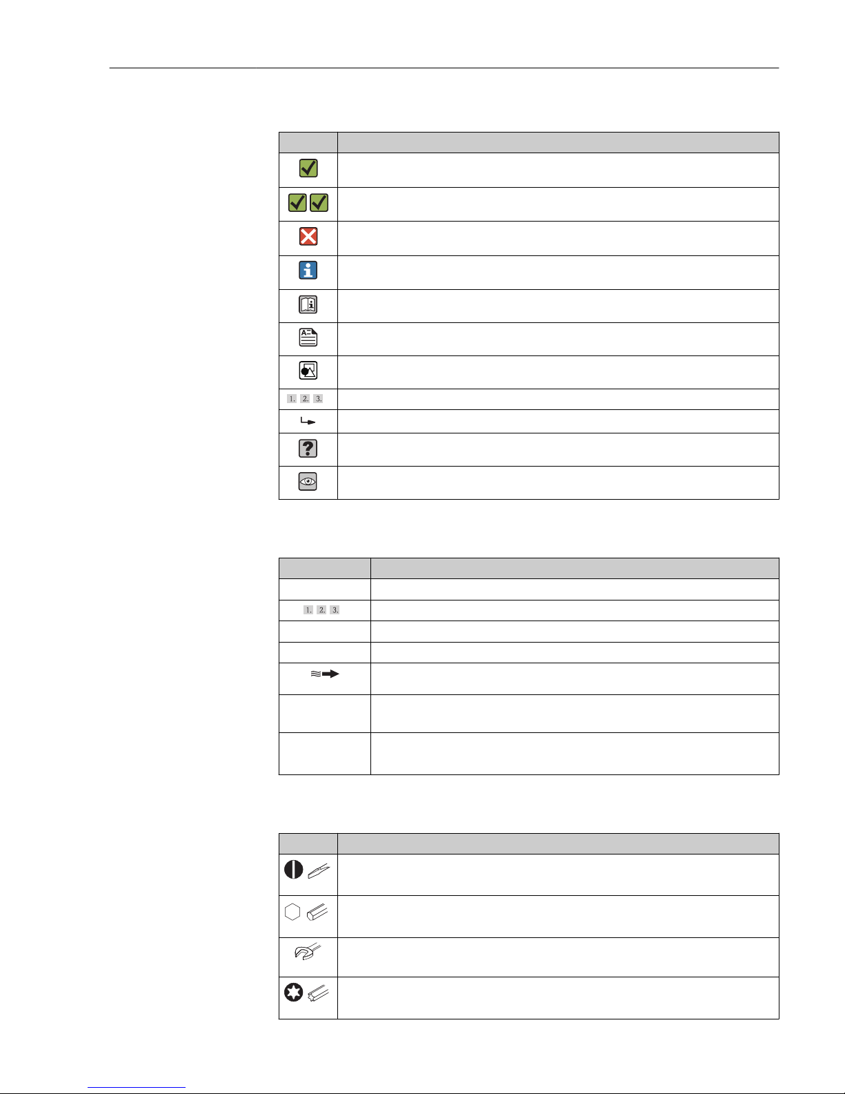
1.2.3 Symbols for certain types of information
Symbol Meaning
Permitted
Procedures, processes or actions that are permitted.
Preferred
Procedures, processes or actions that are preferred.
Forbidden
Procedures, processes or actions that are forbidden.
Tip
Indicates additional information.
Reference to documentation
Reference to page
Reference to graphic
,…,
Series of steps
Result of a step
Help in the event of a problem
Visual inspection
1.2.4 Symbols in graphics
Symbol Meaning
1, 2, 3,... Item numbers
,…,
Series of steps
A, B, C, ... Views
A-A, B-B, C-C, ... Sections
A0013441
Flow direction
-
A0011187
Hazardous area
Indicates a hazardous area.
.
A0011188
Safe area (non-hazardous area)
Indicates a non-hazardous area.
1.2.5 Tool symbols
Symbol Meaning
A0011220
Flat blade screwdriver
A0011221
Allen key
A0011222
Open-ended wrench
A0013442
Torx screwdriver
Page 6

Document information RIA15
6 Endress+Hauser
1.3 Registered trademarks
HART®
Registered trademark of the HART® Communication Foundation
Page 7

RIA15 Safety instructions
Endress+Hauser 7
2 Safety instructions
2.1 Requirements for the personnel
The personnel for installation, commissioning, diagnostics and maintenance must fulfill
the following requirements:
‣
Trained, qualified specialists must have a relevant qualification for this specific function
and task
‣
Are authorized by the plant owner/operator
‣
Are familiar with federal/national regulations
‣
Before beginning work, the specialist staff must have read and understood the
instructions in the Operating Instructions and supplementary documentation as well as
in the certificates (depending on the application)
‣
Following instructions and basic conditions
The operating personnel must fulfill the following requirements:
‣
Being instructed and authorized according to the requirements of the task by the
facility's owner-operator
‣
Following the instructions in these Operating Instructions
2.2 Designated use
The process display unit displays analog process variables or HART ® process variables on
its screen.
The device is powered via the 4 to 20 mA current loop and does not require an additional
power supply.
• The manufacturer accepts no liability for damages resulting from incorrect use or use
other than that designated. It is not permitted to convert or modify the device in any
way.
• Panel-mounted device
The device is designed for installation in a panel and must only be operated in an
installed state.
• Field device:
The device is designed for installation in the field.
• The device may only be operated under the permitted ambient conditions → 52.
2.3 Workplace safety
For work on and with the device:
‣
Wear the required personal protective equipment according to federal/national
regulations.
2.4 Operational safety
Risk of injury.
‣
Operate the device in proper technical condition and fail-safe condition only.
‣
The operator is responsible for interference-free operation of the device.
Conversions to the device
Unauthorized modifications to the device are not permitted and can lead to unforeseeable
dangers.
‣
If, despite this, modifications are required, consult with Endress+Hauser.
Page 8

Safety instructions RIA15
8 Endress+Hauser
Repair
To ensure continued operational safety and reliability,
‣
Carry out repairs on the device only if they are expressly permitted.
‣
Observe federal/national regulations pertaining to repair of an electrical device.
‣
Use original spare parts and accessories from Endress+Hauser only.
Environmental requirements
If a plastic transmitter housing is permanently exposed to certain steam and air mixtures,
this can damage the housing.
‣
If you are unsure, please contact your Endress+Hauser Sales Center for clarification.
‣
If used in an approval-related area, observe the information on the nameplate.
2.5 Product safety
This measuring device is designed in accordance with good engineering practice to meet
state-of-the-art safety requirements, has been tested, and left the factory in a condition in
which it is safe to operate.
It meets general safety standards and legal requirements. It also complies with the EC
directives listed in the device-specific EC Declaration of Conformity. Endress+Hauser
confirms this by affixing the CE mark to the device.
Page 9

RIA15 Product description
Endress+Hauser 9
3 Product description
3.1 Function
Process display unit RIA15 is integrated in the 4 to 20 mA/HART® loop and transmits the
measuring signal in digital form. The process display unit does not require an external
power supply. It is powered directly from the current loop.
In connection with the radar level sensor Micropilot FMR20, the RIA15 can be used to
make the basic settings for the Micropilot FMR20. As a prerequisite the RIA15 must be
ordered with the respective option for the FMR20 basic setting.
The device meets the requirements of the HART® Communication Protocol Specifications
and can be used with devices with HART® Revision ≥ 5.0.
3.2 Operating modes
The process display unit can be used in two different operating modes:
4 to 20 mA mode:
In this operating mode, the process display unit is incorporated into the 4 to 20 mA
current loop and measures the transmitted current. The variable calculated based on the
current value and range limits is displayed in digital form on the 5-digit LCD. In addition,
the associated unit and a bar graph can be displayed.
HART mode:
The device functions as a display unit even when operating with a HART® sensor/actuator.
In this case, the display is also powered from the current loop.
The process display unit can choose to function as a primary master or secondary master
(default) in the HART® loop. When it functions as a master, the device can read process
values from the measuring device and display them. HART® communication operates on
the principle of master/slave. As a general rule, the sensor/actuator is a slave and only
transmits information if a request has been made by the master.
A HART® loop can have a maximum of two HART® masters at any one time. A distinction
is made between primary (e.g. the control system) and secondary master (e.g. handheld
terminal for on-site operation of the measuring devices) for these HART® masters. The
two masters in the loop/in the network cannot be masters of the same type, e.g. they
cannot be two "secondary masters".
If a third HART® master is added to the network, one of the other masters must be
disabled; otherwise a collision occurs in the network.
If the process display unit is operating as "secondary master" and another "secondary
master", e.g. a handheld device, is added to the network, the device interrupts HART®
communication as soon as it detects that there is another "secondary master". The display
alternates between error message C970 "Multi master collision" and "- - -". A measured
value is not displayed in this case. The device leaves the HART® loop for 30 seconds and
tries to re-establish HART® communication once again. Once the additional "secondary
master" is removed from the network, the device continues communication and displays
the measured values of the sensor/actuator once more.
Please note that if two process display units are to be used in a multidrop connection,
one device must be configured as "primary master" and the other as "secondary master"
to prevent a master collision.
In HART mode, the process display unit can show up to four device variables of a
multivariable measuring device. These variables are referred to as the Primary Variable
(PV), Secondary Variable (SV), Tertiary Variable (TV) and Quaternary Variable (QV). These
variables are placeholders for measured values that can be called up using HART®
communication.
Page 10
Product description RIA15
10 Endress+Hauser
For a flowmeter, such as the Promass, these four values can be as follows:
• Primary process variable (PV) →Mass flow
• Secondary process variable (SV) → Totalizer 1
• Third process variable (TV) → Density
• Fourth process variable (QV) → Temperature
The HART® section at the end of these Operating Instructions provides examples of these
four device variables for multivariable measuring devices → 62.
Please refer to the Operating Instructions for each device for details on the variables
that are set as default on the sensor/actuator and how they can be changed.
The process display unit can show each of these values. The individual values must be
activated in the SETUP – HART1 to HART4 menu for this purpose. The individual
parameters are assigned to fixed process variables in the device in this case:
HART1 = PV
HART2 = SV
HART3 = TV
HART4 = QV
For example, if the PV and TV are to be displayed on the process display unit, HART1 and
HART3 must be activated.
The values can either be shown alternately on the process display unit or one value is
displayed continuously and the other values are only shown by pressing '+' or '–'. The
switching time can be configured in the "EXPRT" – "SYSTM" – "TOGTM" menu.
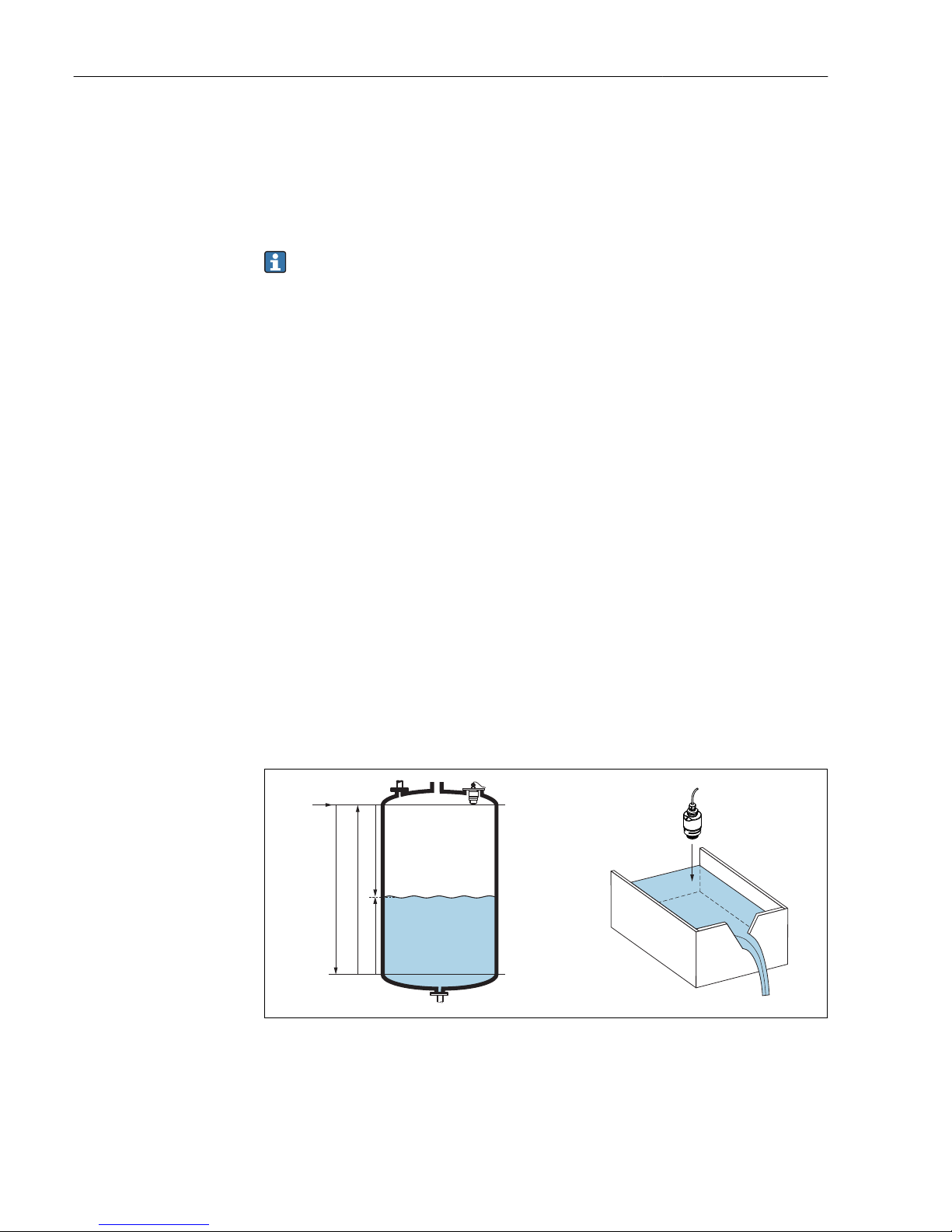
3.2.1 RIA15 as a remote display and for operation of the Micropilot
FMR20
The Micropilot is a "downward-looking" measuring system, operating based on the time-offlight method (ToF). It measures the distance from the reference point (process
connection) to the product surface. Radar impulses are emitted by an antenna, reflected
off the product surface and received again by the radar system.
The FMR20 can be adjusted under the "SETUP → LEVEL" menu (see operating matrix). The
measured value displayed corresponds to the distance measured or, if linearization is
enabled, to a percentage value.
D
Q
R
100%
0%
D
L
F
E
A0028409
1 Setup parameters of the Micropilot
E Empty calibration (= zero)
F Full calibration (= span)
D Measured distance
L Level (L = E - D)
Q Flow rate at measuring weirs or channels (calculated from the level using linearization)
Page 11

RIA15 Product description
Endress+Hauser 11
Input
The reflected radar impulses are received by the antenna and transmitted into the
electronics. A microprocessor evaluates the signal and identifies the level echo caused by
the reflection of the radar impulse at the product surface. This clear signal detection
system benefits from over 30 years' experience with time-of-flight procedures.
The distance D to the product surface is proportional to the time of flight t of the impulse:
D = c · t/2,
where c is the speed of light.
Based on the known empty distance E, the level L is calculated:
L = E – D
Output
The Micropilot is adjusted by entering the empty distance E (= zero point) and the
full distance F (= span).
• Current output: 4 to 20 mA
• Digital output (HART, SmartBlue): 0 to 10 m (0 to 33 ft) or 0 to 20 m (0 to 66 ft)
depending on antenna version
The RIA15 can be used as a local display unit and for the basic configuration of the
Micropilot FMR20 radar level sensor via HART®.
1
4
5
2
3
A0030964
2 Remote operation of the FMR20 via the RIA15
1 PLC
2 Transmitter power supply, e.g. RN221N (with communication resistance)
3 Connection for Commubox FXA195 and Field Communicator 375, 475
4 RIA15 loop-powered process display unit
5 Transmitter
For this, the RIA15 can either be ordered together with the FMR20 via the FMR20 product
structure, or the RIA15 must be ordered separately with option 3 "4 to 20 mA current
signal + HART + FMR20 basic configuration" in feature 030 "Input".
FMR20 product structure, feature 620 "Accessory enclosed":
• Option R4: "Remote display RIA15, non-hazardous"
• Option R5: "Remote display RIA15, hazardous"
RIA15 product structure, feature 030 "Input":
Option 3: "4 to 20 mA current signal + HART + FMR20 basic setting"
The following parameters can then be configured at the FMR20 via the 3 operating keys
on the front of the RIA15:
• Unit
• Empty and full calibration
• Mapping area if the measured distance does not match the actual distance
Further information on the operating parameters → 39
Page 12

Product description RIA15
12 Endress+Hauser
3.3 Input channels
The process display unit has one analog 4 to 20 mA input. In "HART" operating mode, this
channel can be used for measuring and displaying HART® values for a connected sensor/
actuator. In this case, a HART® device can be directly connected to the process display unit
in a point-to-point connection or the process display unit can be incorporated in a HART®
multidrop network.
The RIA15 can be used as a local display unit and for the basic configuration of the
Micropilot FMR20 radar level sensor via HART®.
Page 13

RIA15 Identification
Endress+Hauser 13
4 Identification
4.1 Nameplate
The nameplate is located on the right-hand side of the housing in the case of the field
device, and on the rear of the housing in the case of the panel-mounted device.
Ord. cd.: XXXXXXXX
Ser. no.: XXXXXXXXXXXXXXXXX
Ext. ord. cd.: RIA15-XXXXXXX
Ta= -40...+60°C
Front IP67 Type 4X Encl.
Loop powered 4...20 mA
RIA15
Made in Germany 2012
D-87484 Nesselwang
1
2
4
5
6
7
Class2 circuit or SELV circuit
3
9
8
A0019608
3 Nameplate of the process display unit (example)
1 Order code of the device 6 Device designation
2 Serial number of the device 7 Approvals (optional)
3 Extended order code of the device 8 Input signal
4 Manufacturer's address 9 Housing degree of protection
5 Ambient temperature range
4.2 Scope of delivery
The scope of delivery of the device comprises:
• Panel-mounted device
– Process display unit
– Brief Operating Instructions
– Ex Safety Instructions (optional)
– Fastening fixtures
– HART® communication resistance module (optional)
• Field device
– Process display unit
– Brief Operating Instructions
– Ex Safety Instructions (optional)
– Fastening fixtures for wall/pipe mounting (optional)
– HART® communication resistance module (optional)
– Weather protection cover (optional)
4.3 Certificates and approvals
An overview of all available approvals is provided in the "Technical data" section.
→ 54.
4.3.1 CE mark
The measuring system meets the legal requirements of the applicable EC guidelines. These
are listed in the corresponding EC Declaration of Conformity together with the standards
applied. Endress+Hauser confirms successful testing of the device by affixing to it the CE
mark.
Page 14

Identification RIA15
14 Endress+Hauser
4.3.2 EAC mark
The product meets the legal requirements of the EEU guidelines. The manufacturer
confirms the successful testing of the product by affixing the EAC mark.
4.4 HART® protocol certification
The RIA15 is registered by the HART® Communication Foundation. The device fulfills the
requirements of HCF Specification, Revision 7.1. This version is downwards compatible
with all sensors/actuators with HART® versions ≥ 5.0.
Page 15

RIA15 Installation
Endress+Hauser 15
5 Installation
5.1 Incoming acceptance, transport, storage
Compliance with the permitted environmental and storage conditions is mandatory.
Precise specifications for this are provided in the "Technical data" .
5.1.1 Incoming acceptance
On receipt of the goods, check the following points:
• Is the packaging or the content damaged?
• Is the delivery complete? Compare the scope of delivery against the information on your
order form.
5.1.2 Transport and storage
Please note the following:
• Pack the device so that is protected against impact for storage and transport. The
original packaging provides optimum protection.
• The permitted storage temperature is –40 to +85 °C (–40 to +185 °F); it is possible to
store the device at borderline temperatures for a limited period (48 hours maximum).
5.2 Installation conditions
At temperatures below –25 °C (–13 °F) the readability of the display can no longer be
guaranteed.
5.2.1 Display unit in the panel-mount housing
Permitted ambient temperature range –40 to 60 °C (–40 to 140 °F), horizontal orientation.
IP65 protection at front, IP20 at rear
See "Technical data" section .
5.2.2 Display unit in the field housing
Permitted ambient temperature range –40 to 60 °C (–40 to 140 °F). IP67 protection,
NEMA 4x (aluminum housing).
See "Technical data" section .
5.3 Installation instructions
For the dimensions of the device, see "Technical data" → 53.
Page 16

Installation RIA15
16 Endress+Hauser
5.3.1 Panel housing
1.
2.
A0017762
4 Installation instructions for the panel housing
Installation in a panel with a panel cutout 92x45 mm (3.62x1.77 in), max. panel thickness
13 mm (0.51 in).
1. Slot the device into the panel cutout from the front.
2. Fit the mounting clips on the side of the housing and tighten the threaded rods.
5.3.2 Field housing
Pipe mounting (with optional mounting kit)
The device can be mounted on a pipe with a diameter of up to 50.8 mm (2 in) with the
mounting kit (optionally available).
Page 17

RIA15 Installation
Endress+Hauser 17
2
1
5mm
4mm
1.
2.
3.
4.
TX20
A0017789
5 Mounting the process display unit on a pipe
1 Mounting plate for pipe/wall mounting
2 Weather protection cover (optional)
1. Release the 4 housing screws
2. Open the housing
3. Secure the mounting plate to the rear of the device with 4 screws supplied. The
optional weather protection cover can be secured between the device and the
mounting plate.
4. Guide the two gripper clamps through the mounting plate, fit them around the pipe
and tighten.
Wall mounting
With optionally available mounting kit.
Page 18

Installation RIA15
18 Endress+Hauser
1.
2.
3.
A0017803
6 Mounting the process display unit on a wall
1. Use the mounting plate as a stencil for 2 6 mm (0.24 in) bore holes, 82 mm (3.23 in)
apart, and secure the plate on the wall with 2 screws (not supplied).
2. Open the housing.
3. Secure the display unit on the mounting plate with the 4 screws supplied.
4. Close the cover and tighten the screws.
Without a mounting kit.
1. Open the housing.
2. Use the device as a stencil for 4 6 mm (0.24 in) bore holes, 99 mm (3.9 in) apart on
the horizontal plane, 66 mm (2.6 in) apart on the vertical plane.
3. Secure the display unit on the wall with 4 screws.
4. Close the cover and tighten the housing screws.
5.3.3
Mounting the optional HART® communication resistance
module
Panel housing
The HART® communication resistance module is available as an accessory, see section
Accessories → 49.
Page 19

RIA15 Installation
Endress+Hauser 19
A0020785
7
Mounting the optional HART® communication resistance module
1. Unplug the pluggable terminal block.
2.
Plug terminal block into the suitable plug-in position on the HART® communication
resistance module.
3.
Plug the HART® communication resistance module into the plug-in position on the
housing.
Field housing
The HART® communication resistance module is available as an accessory, see section
Accessories → 49.
A0020844
8
Mounting the optional HART® communication resistance module
1. Unplug the pluggable terminal block.
2.
Plug terminal block into the suitable plug-in position on the HART® communication
resistance module.
3.
Plug the HART® communication resistance module into the plug-in position in the
housing.
5.4 Post-installation check
5.4.1 Display unit in the panel-mount housing
• Is the seal undamaged?
• Are the mounting clips securely fastened on the housing of the device?
• Are the threaded rods properly tightened?
• Is the device located in the center of the panel cutout?
Page 20

Installation RIA15
20 Endress+Hauser
5.4.2 Display unit in the field housing
• Is the seal undamaged?
• Is the housing firmly screwed to the mounting plate?
• Is the mounting bracket firmly secured on the wall/pipe?
• Are the housing screws firmly tightened?
Page 21

RIA15 Wiring
Endress+Hauser 21
6 Wiring
L
WARNING
Danger! Electric voltage!
‣
The entire connection of the device must take place while the device is de-energized.
Only certified devices (optionally available) may be connected in the hazardous area
‣
Observe corresponding notes and wiring diagrams in the Ex-specific supplement to
these Operating Instructions. If you have any questions, please do not hesitate to
contact your E+H representative.
NOTICE
SELV/Class 2 device
‣
The device may only be powered by a power unit with an energy-limited circuit in
accordance with IEC 61010-1: 'SELV or Class 2 circuit'.
Device destroyed if current too high
‣
Do not operate the device at a voltage source without a current limiter. Instead, operate
the device only in the current loop with a transmitter.
• Panel housing:
The terminals are located on the rear of the housing.
• Field housing:
The terminals are located inside the housing. The device has two M16 cable entries. The
housing must be opened for wiring purposes.
Operation of the spring terminals
A0020848
9 Operation of the spring terminals
1. When using rigid cables with a ferrule, just plug the cable into the terminal. No tools
required. With flexible wires the spring mechanism of the terminal must be operated
as shown in step 2.
2. In order to loosen the cable, push the spring mechanism in completely using a
screwdriver or other suitable tool and pull out the cable.
6.1 Quick wiring guide
Terminal Description
+ Positive connection, current measurement
- Negative connection, current measurement (without backlighting)
LED Negative connection, current measurement (with backlighting)
Auxiliary terminals (electrically connected internally)
Functional grounding:
• Panel-mounted device:
Terminal on the rear of the housing
• Field device:
Terminal in the housing
Page 22

Wiring RIA15
22 Endress+Hauser
6.2 Connection in 4 to 20 mA mode
The following diagrams show how the process display unit is connected in 4 to 20 mA
mode.
Connection without backlighting Connection with backlighting
Connection with transmitter power supply
and transmitter
LED
-
+
-
-
+
+
I
Y
1
A0017704
1 Transmitter power supply
+
+
I
Y
1
-
-
LED
-
+
A0017705
1 Transmitter power supply
Connection with transmitter power supply
and transmitter using the auxiliary
terminal
-
-
+
+
I
Y
1
LED
-
+
A0017706
1 Transmitter power supply
+
+
I
Y
1
-
-
LED
-
+
A0017707
1 Transmitter power supply
Connection with PLC and transmitter
-
-
+
+
I
Y
1
LED
-
+
A0019720
1 PLC
-
-
+
+
I
Y
1
LED
-
+
A0019721
1 PLC
Connection without transmitter power
supply directly in the 4 to 20 mA circuit
+
2
-
I
Y
LED
-
+
A0017708
2 4 to 20 mA power source
+
2
-
I
Y
LED
-
+
A0017709
2 4 to 20 mA power source
6.3 Connection in HART mode
The following diagrams show how the process display unit is connected in HART mode.
6.3.1
HART® connection
NOTICE
Undefined behavior due to incorrect wiring of an actuator
‣
When installing the process display unit together with an actuator, the Operating
Instructions for the actuator must be followed!
The HART® communication resistance of 230 Ω in the signal line is always necessary
in the case of a low-impedance power supply. It must be installed between the power
supply and the display unit.
Page 23

RIA15 Wiring
Endress+Hauser 23
Circuit diagram / Description
2-wire sensor with
process display unit
and transmitter power
supply, without
backlighting
Y
I
R
s
DC
1
2
3
LED
-
+
A0019567
1 Sensor
2 Power supply
3
HART® resistance
2-wire sensor with
process display unit
and transmitter power
supply, with
backlighting
Y
I
R
s
DC
1
2
3
LED
-
+
A0019568
1 Sensor
2 Power supply
3
HART® resistance
4-wire sensor with
process display unit
and transmitter power
supply, without
backlighting
1
3
Y
I
2
4
LED
-
+
A0019570
1
HART® resistance
2 Current measuring device (optional)
3 Sensor
4 Power supply 4-wire device
4-wire sensor with
process display unit
and transmitter power
supply, with
backlighting
1
3
Y
I
2
4
LED
-
+
A0019571
1
HART® resistance
2 Current measuring device (optional)
3 Sensor
4 Power supply 4-wire device
Page 24

Wiring RIA15
24 Endress+Hauser
Circuit diagram / Description
Current output with
process display unit
and actuator (e.g.
actuator valve),
without backlighting
1
3
2
LED
-
+
A0019573
1 Actuator
2 Power supply 4-wire device
3 Current output
Current output with
process display unit
and actuator (e.g.
actuator valve), with
backlighting
1
3
2
LED
-
+
A0019574
1 Actuator
2 Power supply 4-wire device
3 Current output
Multi-drop 2-wire
sensors with process
display unit and
transmitter power
supply
R
s
DC
1
2
3
Y
I
LED
-
+
Y
I
Y
I
A0019575
1 Sensors
2 Power supply
3
HART® resistance
Multi-drop 2-wire
sensors with process
display unit and
transmitter power
supply, with
backlighting
R
s
DC
1
2
3
I
Y
Y
I
Y
I
LED
-
+
A0019722
1 Sensors
2 Power supply
3
HART® resistance
Page 25

RIA15 Wiring
Endress+Hauser 25
Circuit diagram / Description
2-wire sensor with
process display unit
and active barrier
RN221N as
transmitter power
supply
Y
I
1
2
3
O+
O-
RN221N
R
s
R
LED
-
+
A0019576
1 Sensor
2
HART® primary master
3
HART® resistance
Optional HART® communication resistance module
A HART® communication resistance module is available as an accessory, see the
"Accessories" section → 49.
Please refer to the section on installation when mounting the HART® communication
resistance module → 18
Wiring
Circuit diagram / Description
2-wire sensor with
process display unit
and transmitter power
supply, without
backlighting
1
LED
-
+
3
2
Y
I
R
s
DC
A0020839
1
HART® communication resistance module
2 Sensor
3 Power supply
2-wire sensor with
process display unit
and transmitter power
supply, with
backlighting
1
3
2
Y
I
R
s
DC
LED
-
+
A0020840
1
HART® communication resistance module
2 Sensor
3 Power supply
Page 26

Wiring RIA15
26 Endress+Hauser
Circuit diagram / Description
4-wire sensor with
process display unit
and transmitter power
supply, without
backlighting
1
3
Y
I
2
LED
-
+
A0020837
1
HART® communication resistance module
2 Power supply 4-wire device
3 Sensor
4-wire sensor with
process display unit
and transmitter power
supply, with
backlighting
1
3
Y
I
2
LED
-
+
A0020838
1
HART® communication resistance module
2 Power supply 4-wire device
3 Sensor
Configuration of HART® devices
The process display unit cannot be used to configure connected HART® devices.
Configuration is done using the Field Xpert SFX100 device configurator, for example.
1
2
3
5
4
A0019580
10
Configuration of HART® devices; example TMT162
1
HART® primary master (e.g. PLC)
2
HART® resistance
3 RIA15 process display unit
4
HART® handheld, e.g. Field Xpert SFX100
5
Sensor with HART® transmitter, e.g. TMT162
Page 27

RIA15 Wiring
Endress+Hauser 27
6.4 Wiring with switchable backlighting
An additional current-limited current source is required to implement switchable
backlighting, e.g. active barrier RN221N. This current source is used to supply the LED
backlighting of up to 7 RIA15 process display units without causing an additional voltage
drop in the measurement loop. The backlighting can be switched on and off using an
external switch.
The following shows connection examples for the hazardous area. Wiring is similar
for the non-hazardous area; however, it is not necessary to use Ex-certified devices.
6.4.1 Connection diagram for one process display unit
LED
-
+
-
+
I
Y
1
+
-
O-
LNPE
O+
7
6
5
+
-
O-
LNPE
O+
8
4
2
3
9
10
A0028248
1 Process display unit RIA15
2 3-wire connector, e.g. WAGO 221 series
3 2-wire sensor
4 Terminal block on top-hat rail
5 Active barrier, e.g. RN221N
6 4 to 20 mA output to the control unit
7 Power supply
8 Current source, e.g. RN221N
9 Switch to activate backlighting
10 Power supply
Page 28

Wiring RIA15
28 Endress+Hauser
6.4.2 Connection diagram for multiple process display units
LED
-
+
-
+
I
Y
1
+
-
O-
LNPE
O+
7
6
5
+
-
O-
LNPE
O+
9
8
10
4
2
3
LED
-
+
-
+
I
Y
LED
-
+
-
+
I
Y
+
-
O-
LNPE
O+
+
-
O-
LNPE
O+
11
A0028249
1 Process display unit RIA15
2 3-wire connector, e.g. WAGO 221 series
3 2-wire sensor
4 Terminal block on top-hat rail
5 Active barrier, e.g. RN221N
6 4 to 20 mA output to the control unit
7 Power supply
8 Current source, e.g. RN221N
9 Switch to activate backlighting
10 Power supply
11 Can be extended to 7 devices
Page 29

RIA15 Wiring
Endress+Hauser 29
6.5 Inserting the cable, field housing
TX20
2.
3.
4.
1.
A0017830
11 Inserting the cable, field housing
Inserting the cable, field housing, connection without transmitter power supply (example)
1. Release the housing screws
2. Open the housing
3. Open the cable gland (M16) and insert the cable
4. Connect the cable incl. functional grounding and close the cable gland
6.6 Shielding and grounding
Optimum electromagnetic compatibility (EMC) can only be guaranteed if the system
components and, in particular, the lines are shielded and the shield forms as complete a
cover as possible. A shield coverage of 90% is ideal.
• To ensure an optimum EMC protective effect when communicating with HART®, connect
the shield as often as possible to the reference ground.
• For reasons of explosion protection, you should refrain from grounding however.
To comply with both requirements, three different types of shielding are possible when
communicating with HART®:
• Shielding at both ends
• Shielding at one end on the feed side with capacitance termination at the field device
• Shielding at one end on the feed side
Experience shows that the best results with regard to EMC are achieved in most cases in
installations with one-sided shielding on the feed side (without capacitance termination at
the field device). Appropriate measures with regard to input wiring must be taken to allow
unrestricted operation when EMC interference is present. These measures have been
taken into account for this device. Operation in the event of disturbance variables as per
NAMUR NE21 is thus guaranteed. Where applicable, national installation regulations and
guidelines must be observed during the installation! Where there are large differences in
potential between the individual grounding points, only one point of the shielding is
connected directly with the reference ground. In systems without potential equalization,
Page 30

Wiring RIA15
30 Endress+Hauser
therefore, cable shielding of fieldbus systems should only be grounded on one side, for
example at the supply unit or at safety barriers.
NOTICE
If the shielding of the cable is grounded at more than one point in systems without
potential matching, power supply frequency equalizing currents can occur that
damage the signal cable or have a serious effect on signal transmission.
‣
In such cases the shielding of the signal cable is to be grounded on one side only, i.e. it
must not be connected to the ground terminal of the housing. The shield that is not
connected should be insulated!
6.7 Connecting to functional grounding
6.7.1 Panel-mounted device
For EMC reasons, the functional grounding should always be connected. When the device
is used in the hazardous area (with optional Ex approval) the connection is obligatory.
1
A0018894
12 Functional grounding terminal on panel-mounted device
6.7.2 Field device
For EMC reasons, the functional grounding should always be connected. When used in the
hazardous area (with optional Ex approval), the connection is obligatory and the field
housing must be grounded via a grounding screw fitted on the outside of the housing.
TX20
A0018895
13 Functional grounding terminal in field housing
Page 31

RIA15 Wiring
Endress+Hauser 31
TX20
A0018908
14 Ground terminal on field housing
6.8 Degree of protection
6.8.1 Field housing
The devices meet all the requirements of IP67. It is absolutely essential to comply with the
following points to ensure this protection is guaranteed after mounting or servicing the
device:
• The housing seal must be clean and undamaged when inserted into the groove. The seal
must be cleaned, dried or replaced if necessary.
• The cables used for connection must be of the specified outside diameter (e.g. M16 x
1.5, cable diameter 5 to 10 mm (0.2 to 0.39 in)).
• Mount the measuring device in such a way that the cable entries point downwards.
• Replace unused cable entries with dummy plugs.
• The housing cover and the cable entries must be firmly tightened.
6.8.2 Panel housing
The front of the device meets the requirements of IP65. It is absolutely essential to comply
with the following points to ensure this protection is guaranteed after mounting or
servicing the device:
• The seal between the front of the housing and the panel must be clean and undamaged.
The seal must be cleaned, dried or replaced if necessary.
• The threaded rods of the panel mounting clips must be firmly tightened.
6.9 Post-connection check
Device condition and specifications Notes
Are cables or the device damaged? Visual inspection
Electrical connection Notes
Does the supply current match the specifications on the nameplate? -
Are the cables, incl. functional grounding, connected correctly and strain-relieved? -
Field housing: Are the cable glands securely closed? -
Page 32

Operation RIA15
32 Endress+Hauser
7 Operation
1
2
3
4
5
6
7
8
A0017719
15 Display and operating elements of the process display unit
1 Symbol: operating menu disabled
2 Symbol: error
3 Symbol: warning
4
Symbol: HART® communication active
5 Operating keys "-", "+", "E"
6 14-segment display for unit/TAG
7 Bar graph with indicators for under range and over range
8 5-digit 7-segment display for measured value, digit height 17 mm (0.67 in)
The device is operated using three operating keys on the front of the housing. The device
setup can be disabled with a 4-digit user code. If the setup is disabled, a padlock symbol
appears on the display when an operating parameter is selected.
A0017716
Enter key; calling up the operating menu, confirming the option/setting parameters in the
operating menu
A0017714
Selecting and setting/changing values in the operating menu; pressing the '-' and '+' keys
simultaneously takes the user back up a menu level. The configured value is not saved.
A0017715
7.1 Operating functions
The operating functions of the process display unit are divided into the following menus.
The individual parameters and settings are described in the "Commissioning" section.
If the operating menu is disabled by means of a user code, the individual menus and
parameters can be displayed but not changed. To change a parameter, the user code
must be entered. As the display unit can only display digits in the 7-segment display
and not alphanumeric characters, the procedure for number parameters is different to
that for text parameters.
If the operating position contains only numbers as parameters, the operating position
is displayed in the 14-segment display and the configured parameter is displayed in
the 7-segment display. To edit, press the 'E'-button followed by the user code.
If the operating position contains text parameters, only the operating position is
initially displayed in the 14-segment display. If the 'E' button is pressed again, the
configured parameter is displayed in the 14-segment display. To edit, press the '+'
button followed by the user code.
Page 33

RIA15 Operation
Endress+Hauser 33
Setup
(SETUP)
Basic device settings
Diagnostics
(DIAG)
Device information, display of error messages
Expert
(EXPRT)
Expert settings for the device setup → 37
The Expert menu is protected from editing by an access code (default 0000).
Page 34

Commissioning RIA15
34 Endress+Hauser
8 Commissioning
8.1 Post-installation check and switching on the device
Perform the final checks before commissioning the device:
• Checklist for "post-installation check" → 19.
• Checklist for "post-connection check" → 31.
The device starts after being connected to the 4 to 20 mA/HART® circuit. The firmware
version appears on the display during the start-up phase.
When the device is being commissioned for the first time, program the setup in accordance
with the descriptions in the Operating Instructions.
If you are commissioning a device that is already configured or preset, the device
immediately starts measuring the current or making a HART® request as defined in the
settings. The values of the currently activated process variables appear in the display.
Devices with the "Level" option for the FMR20 are preconfigured as follows at the factory:
• Operating mode: HART mode
• Decimal point HART: 2 decimal places
• Display HART3: Off
• Display HART4: Off
Remove the protective film from the display as this would otherwise affect the
readability of the display.
8.2 Operating matrix
Setup menu (SETUP)
Parameters Values visible at Description
LEVEL FMR20
option
This menu contains the parameters for configuring the
FMR20 level transmitter.
The individual parameters are described in the section
"Operating matrix in conjunction with the Micropilot
FMR20" → 39.
MODE 4-20
HART
Select the operating mode for the display unit
4-20: The circuit's 4 to 20 mA signal is displayed
HART: Up to four HART® variables (PV, SV, TV, QV) of a
sensor/actuator in the loop can be displayed.
For the "Level" option for FMR20: default = HART
DECIM 0 DEC
1 DEC
2 DEC
3 DEC
4 DEC
MODE =
4-20
Number of decimal places for display
For the "Level" option for FMR20: default = 2 DEC
SC__4 Numerical value
–19 999 to 99 999
Default: 0.0
MODE =
4-20
5-digit value (number of decimal places as configured
under DECIM) for scaling the measured value at 4 mA
Example: SC__4 = 0.0 Þ 0.0 displayed at 4 mA
measuring current
The unit selected under UNIT is used to display the value.
SC_20 Numerical value
–19 999 to 99 999
Default: 100.0
MODE =
4-20
5-digit value (number of decimal places as configured
under DECIM) for scaling the measured value at 20 mA
Example: SC_20 = 100.0 Þ 100.0 displayed at 20 mA
measuring current
The unit selected under UNIT is used to display the value.
Page 35

RIA15 Commissioning
Endress+Hauser 35
Setup menu (SETUP)
Parameters Values visible at Description
UNIT %
°C
°F
K
USER
MODE =
4-20
Use this function to select the unit for displaying the
value. If "USER" is selected, a user-defined unit can be
entered in the TEXT parameter.
TEXT Customized text,
5-digit
MODE =
4-20
User-defined unit, only visible if the "USER" option has
been selected under UNIT.
SCAN NO
YES
MODE =
HART
Select "YES" to start scanning. All addresses are then
automatically scanned once in a HART® application until
a sensor/actor is found. Scanning runs from 0 to 63. Only
addresses up to 15 are permitted for HART 5. Once the
address of the sensor/actor whose values are to be
displayed is found, the address must be confirmed by
pressing the 'E' key. This address is adopted and is used
even after a device restart.
By pressing the '+' or '–' key, it is possible to search for
other addresses.
Pressing '+'- and '-' simultaneously will cancel scanning.
If "NO" is selected, scanning is not active. The address of
the sensor/actor, whose values are to be displayed on the
process display unit, must be configured manually using
the operating keys.
ADDR Numerical value
0 to 63
Default: 0
MODE =
HART
Use this function to enter manually the address of the
HART® sensor/actor whose values are to be displayed.
If the address of the HART® slave is changed, it
must also be changed on the process display unit.
To do this, either enter the address manually or
search using SCAN mode.
MTYPE PRIM
SEC
MODE =
HART
Use this function to select the HART® master type:
PRIM = Primary master
SEC = Secondary master
HART1-HART4 MODE =
HART
Use this function to select which HART® value of a
sensor/actor (PV, SV, TV, QV) should be activated and
configured:
HART1 = PV
HART2 = SV
HART3 = TV
HART4 = QV
Press the E key to open the configuration submenu.
DISP1 –DISP4 OFF
MAN
AUTO
MODE =
HART
Use this function to select how or whether the value
should be displayed.
OFF: Value is not displayed
MAN: You can manually scroll through activated HART®
values by pressing '+' or '–'. Otherwise the values are not
displayed. If all four HART® values (HART1 to HART4)
are set to "MAN", HART1 (PV) is displayed if you do not
scroll manually through the values.
AUTO: Activated HART® values are shown alternately
(switching time can be configured in the EXPRT menu
under "TOGTM"). If one value is set to AUTO, this value is
displayed continuously on the device.
For the "Level" option for FMR20: default for DISP3 and
DISP4 = OFF
DEC1 – DEC4 0 DEC
1 DEC
2 DEC
3 DEC
4 DEC
MODE =
HART
Number of decimal places
Page 36

Commissioning RIA15
36 Endress+Hauser
Setup menu (SETUP)
Parameters Values visible at Description
BGLO1BGLO4
Numerical value
–19 999 to 99 999
Default: 0.0
MODE =
HART
5-digit value (number of decimal places as configured
under DEC1-DEC4) for scaling the lower range of the bar
graph for HART1 - HART4.
The bar graph is disabled if BGLOx and BGHIx are set to
"0.0".
BGHI1-BGHI4 Numerical value
–19 999 to 99 999
Default: 0.0
MODE =
HART
5-digit value (number of decimal places as configured
under DEC1-DEC4) for scaling the upper range of the bar
graph for HART1 - HART4.
The bar graph is disabled if BGLOx and BGHIx are set to
"0.0".
UNIT1-UNIT4 HART
%
°C
°F
K
USER
MODE =
HART
Use this function to select the unit for displaying the
HART® value.
If "HART" is selected, the unit configured on the sensor/
actor is automatically adopted for the relevant HART®
value. Only units with a maximum of 5 characters can be
shown. Longer units are displayed as unit code "UCxxx".
The table in the HART® communication section at the
end of these Operating Instructions provides an overview
of the units that can be displayed.
If "USER" is selected, a user-defined unit can be entered in
the TEXT1-TEXT4 parameter.
TEXT1-TEXT4 Customized text,
5-digit
MODE =
HART
User-defined unit. Only visible if the "USER" option has
been selected under UNIT
Diagnostics menu (DIAG)
Parameters Values Description
AERR Read only The current diagnostic message appears on the display. If two or more
messages occur simultaneously, the message with the highest priority
is shown on the display.
LERR Read only The last diagnostic message with the highest priority appears on the
display.
FWVER Read only The firmware version appears on the display.
TERR
1)
Read only Displays the diagnostic code/error code pending at Endress+Hauser
HART® transmitters/sensors. Please refer to the Operating
Instructions of the relevant Endress+Hauser transmitter/sensor for
additional information about the meaning of the diagnostic number
and the remedial measures.
1) For Endress+Hauser transmitters/sensors with HART® communication, the diagnostic code/error code
currently pending can be queried via Endress+Hauser command #231. This command is only supported by
Endress+Hauser transmitters/sensors. Therefore, the TERR parameter is not visible if third-party devices
are connected to the RIA15.
Page 37

RIA15 Commissioning
Endress+Hauser 37
Expert menu (EXPRT); a code must be entered
In addition to all the parameters in the Setup menu, the Expert menu also contains the parameters
described in this table. If you call up the Expert menu, you will be asked to enter the user code (UCODE,
default: 0000).
Parameters Values visible at Description
LEVEL MODE =
HART
This menu contains the parameters for
configuring the FMR20 level transmitter.
The Level menu and all the related submenus
are only visible if the RIA15 has been ordered
with the "FMR20 basic configuration" option. The
basic settings can be made at the Micropilot
FMR20 radar level sensor via the RIA15 using
this menu. Description of the individual
parameters → 40
SYSTM
UCODE Numerical value 0000
to 9999
Default: 0000
4-digit user code
With the user code it is possible to protect the
device setup from unauthorized modifications. If
the setup is disabled, a padlock symbol appears
on the display when an operating parameter is
selected.
The user code is not active with the default
setting "0000". This means that setup parameters
can be changed without entering the code. The
code must always be entered for the Expert
menu, even for the default setting.
FRSET NO
YES
Resets the device setup. The values are reset to
the preset values for preconfigured devices, and
to the default values for all other devices. Select
"YES" and press "E" by way of confirmation to
reset the device.
TOGTM 5
10
15
20
MODE =
HART
Use this function to select the switching time in
seconds between HART® values if "AUTO" was
selected in the DISP1-DISP4 menu.
INPUT The following parameters are available in
addition to the parameters from the Setup menu.
Page 38

Commissioning RIA15
38 Endress+Hauser
Expert menu (EXPRT); a code must be entered
In addition to all the parameters in the Setup menu, the Expert menu also contains the parameters
described in this table. If you call up the Expert menu, you will be asked to enter the user code (UCODE,
default: 0000).
Parameters Values visible at Description
CURV LINAR
SQRT
Use this to select the calculation function for
the process value (for MODE = 4-20)
LINAR (scaling with SC__4 and SC_20):
Process value = (mA value - 4)/16 * (SC_20 SC__4) + SC__4 + OFFST
SQRT (square root extraction and scaling):
Process value = Square root((mA value - 4)/16)
* (SC_20 - SC__4) + SC__4 + OFFST
Negative values when calculating the square root
are set to 0.
Use this to select the calculation function for
the HART1 value (PV) (for MODE = HART)
LINAR:
HART1 value (PV) = "exported PV value" * FACT1
+ OFFS1
SQRT (square root extraction and scaling with
BGLO1 and BGHI1):
HART1 value (PV) = (square root("exported
percentage PV value" / 100) * (BGHI1 - BGLO1)
+ BGLO1) * FACT1 + OFFS1
Negative values when calculating the square root
are set to 0.
Example for SQRT:
• exported percentage PV value = 50
• BGLO1 = 100.0
• BGHI1 = 200.0
• FACT1 = 1
• OFFS1 = 0.0
HART1 value (PV) = (square root(50/100) *
(200 - 100) + 100) * 1 + 0 = 170.7
NAMUR NO
YES
MODE =
4-20
Use this function to define the error limits in
accordance with standard NAMUR NE 43
→ 41
RNGLO Numerical value NAMUR =NOLower range limit. An error message is displayed
if the measured current falls below this limit.
RNGHI Numerical value NAMUR =NOUpper range limit. An error message is displayed
if the measured current exceeds this limit.
OFFST Numerical value
–19 999 to 99 999
MODE =
4-20
Use this function to enter an offset value to
display the measured value.
FACT1-FACT4 1E-6
1E-5
1E-4
1E-3
1E-2
1E-1
1
1E1
1E2
1E3
1E4
1E5
1E6
MODE =
HART
As the display is limited to 5 characters, the
measured value must be multiplied by a factor if
necessary.
For example: conductivity 0.00003 S multiplied
by factor 1E6 Þ 30.000 µS.
If a factor is used, it is recommended to set
the unit under UNIT1-4 to "UNIT" and to
enter user-defined text because the unit
automatically delivered via HART® no
longer matches the displayed value.
OFFS1-OFFS4 Numerical value
–19 999 to 99 999
MODE =
HART
Use this function to enter an offset value to
display the HART1-HART4 measured value.
If a factor is used, the offset is added to the
multiplied value (displayed value = measured
value*factor + offset)
Page 39

RIA15 Commissioning
Endress+Hauser 39
Expert menu (EXPRT); a code must be entered
In addition to all the parameters in the Setup menu, the Expert menu also contains the parameters
described in this table. If you call up the Expert menu, you will be asked to enter the user code (UCODE,
default: 0000).
Parameters Values visible at Description
EXP1-EXP4 YES
NO
MODE =
HART
Measured value display for measured values
greater than 99999.
• YES: If the display overruns, the measured
value is displayed in exponential notation.
• NO: Values with more than 5 digits are not
displayed if the display overruns. Value is
displayed with leading zeros.
Example: Measured value: 130002.4
YES => 1.30E5
NO => 0002.4
DIAG
CNTHI Read only MODE =
HART
Counter for the number of values transmitted via
HART® , 5 top positions. The counter goes back
to 0 after a device restart or scan.
CNTLO Read only MODE =
HART
Counter for the number of values transmitted via
HART® , 5 bottom positions. The counter goes
back to 0 after a device restart or scan.
RETRY Read only MODE =
HART
Counter for the number of retries to establish
HART® communication. The counter goes back
to 0 after a device restart or scan.
FAIL Read only MODE =
HART
Counter for the number of failed attempts to
establish HART® communication. The counter
goes back to 0 after a device restart or scan.
HLEVL
Tx mV Read only MODE =
HART
Value of the peak-to-peak level of the
transmission signal in mV
Rx mV Read only MODE =
HART
Value of the peak-to-peak level of the received
signal in mV
NOISE Read only MODE =
HART
Displays the level of the interference signal
LO = low interference signal
MED = medium interference signal
HI = high interference signal
Rc Ω Read only MODE =
HART
Value of the total resistance in the HART® loop
in Ohm
8.3 Operating matrix in conjunction with the Micropilot
FMR20
In the HART mode, it is possible to use the RIA15 with the option for the FMR20 for the
basic setting of the Micropilot FMR20 radar level sensor.
Further information on the FMR20, see corresponding Operating Instructions
→ BA01578F.
FMR20 basic setting
The RIA15 must be in the HART mode (MODE = HART) to make the basic settings. The
LEVEL menu is not visible in the analog mode (MODE = 4-20).
1. Press the key.
The Setup menu opens.
2. Press the key.
The LEVEL submenu opens.
Page 40

Commissioning RIA15
40 Endress+Hauser
3. Set the desired parameters. For parameter descriptions, see the following table.
Setup -> Level (LEVEL) menu
The Level menu is only visible if the RIA15 has been ordered with the "FMR20 basic setting" option and
the display unit is operated in the HART mode (MODE = HART). The basic settings can be made at the
Micropilot FMR20 radar level sensor via the RIA15 using this menu.
Parameters Values visible at Description
Level MODE =
HART
This menu contains the parameters for configuring the
FMR20 level transmitter.
The Level menu and all the related submenus are only
visible if the RIA15 has been ordered with the "FMR20
basic configuration" option. The basic settings can be
made at the Micropilot FMR20 radar level sensor via the
RIA15 using this menu.
UNIT m
ft
Select the displayed unit
EMPTY Numerical value
0 to 100 m
Default 2 m
Empty calibration using keys -,+,E.
Enter distance from process connection to min. level
FULL Numerical value
–19 999 to 99 999
Full calibration using keys -,+,E.
Enter span from max. level to min. level
DIST Measured value Measured value (measured distance)
MAP
DI OK To be selected if the distance displayed matches the
actual distance. The device then records a mapping.
MAN To be selected if the range of mapping is to be defined
manually in the 'Mapping end point' parameter. A
comparison between the distance displayed and the
actual distance is not necessary in this case. Mapping
becomes active after approx. 20 s.
DI UN To be selected if the actual distance is unknown. No
mapping is recorded.
FACT To be selected if the present mapping curve (if one
exists) is to be deleted. The device returns to the "Confirm
distance" parameter and a new mapping can be recorded.
Page 41

RIA15 Troubleshooting
Endress+Hauser 41
9 Troubleshooting
9.1 Error limits as per NAMUR NE 43
In Mode=4-20, the device can be configured for error limits as per NAMUR NE 43
→ 37.
The device displays an error message if a value is outside these limits.
Current value Error Diagnostic code
≤ 3.6 mA Under range F100
3.6 mA < x ≤ 3.8 mA Unpermitted measured value S901
20.5 mA ≤ x < 21.0 mA Unpermitted measured value S902
> 21.0 mA Over range F100
9.2 Diagnostic messages
If several errors are pending simultaneously, the device always displays the error with
the highest priority.
1 = Highest priority
Diagnostic
number
Short text Corrective measure Status signal Diagnostic
behavior
Priority
Diagnostics for the sensor
F100 Sensor error • Check electrical wiring
• Check sensor
• Check sensor settings
F Alarm 6
S901 Input signal
too small
• Check transmitter output for defect and conformity error
• Check transmitter for incorrect configuration
S Warning 4
S902 Input signal
too large
S Warning 5
Diagnostics for the electronics
F261 Electronics
module
Replace electronics F Alarm 1
F283 Memory
content
• Restart device
• Reset device
• Replace electronics
F Alarm 2
F431 Factory
calibration
Replace electronics F Alarm 3
Diagnostics for the configuration
M561 Display
overshoot
Check scaling M Warning 7
9.2.1 HART® diagnostic messages
If several errors are pending simultaneously, the device always displays the error with
the highest priority.
1 = Highest priority
Page 42

Troubleshooting RIA15
42 Endress+Hauser
Diagnostic
number
Short text Corrective measure Status signal Diagnostic
behavior
Priority
F960 HART®
communication (slave
not responding)
• Verify HART slave address
• Check electrical wiring (HART®)
• Check HART® function sensor/actor
F Alarm 8
C970 Multi-master collision • Check additional master in the HART® network
(e.g. handheld).
• Check master setting (secondary/primary)
C Check 9
F911 HART® slave device
error (HART® Field
Device Status)
Check sensor/actor configuration or check for defects F Alarm 10
S913 HART® slave current
output saturated
(HART® Field Device
Status)
• Commissioning: Check sensor/actor for incorrect
configuration, check sensor/actor configuration
• Operation: Process parameter outside valid range
S Warning 11
S915 HART® slave variable
outside limits of range
(HART® Field Device
Status)
S Warning 12
9.2.2 Other diagnostics in the HART® mode
The process display unit has an integrated HART® diagnostics function. This function can
be used to estimate the HART® signal level, the applicable communication resistance, and
the noise of the network.
The display unit can measure and display the following values:
Parameters Description Display
Tx mV Process display unit signal level mV Peak-to-peak level of the
transmission signal
Rx mV Slave signal level mV Peak-to-peak level of the received
signal
NOISE Weighting of the interference
signal
LO / MED / HI Categorization of the interference
into low, medium or high
Rc Ω Effective communication resistance Ω Resistance in Ohm
The values can be called up in the EXPRT – DIAG – HLEVL menu.
Measuring the transmission signal level "Tx":
The Tx measurement can be used to assess the signal level of the transmission signal.
Ideally this should be between 200 mV and 800 mV . The following values are displayed:
Tx < 120 mV 120 to 200 mV 200 to 800 mV 800 to 850 mV > 850 mV
Display LO Level in mV HI
Bargraph < < 0 to 100 % > >
Measuring the received signal level "Rx":
The Rx measurement can be used to assess the signal level of the received signal. Ideally
this should be between 200 mV and 800 mV .
The Rx signal value that is displayed is a filtered signal level as assessed by the process
display unit. In this way, the value measured externally and the displayed value can differ
from one another, for example in the case of a trapezoidal received signal.
Page 43

RIA15 Troubleshooting
Endress+Hauser 43
The following values are displayed:
Rx < 120 mV 120 to 200 mV 200 to 800 mV 800 to 850 mV > 850 mV
Display LO Level in mV HI
Bargraph < < 0 to 100 % > >
Measuring the "NOISE" interference signal:
When the interference signal level is measured, the interference signal determined is
divided into three categories:
LO = low
MED = medium
HIGH = high
The noise measurement is also a filtered signal level as assessed by the process display
unit. The value measured externally and the displayed value can therefore differ from one
another, depending on the frequency and the form of the signal.
With low wanted signal levels (Rx, Tx), transmission errors can occur even if the
interference signal level is low ("LO" displayed).
Measuring the communication resistance "Rc":
The "Rc" measurement can be used to determine the network resistance of the HART®
network. Ideally this should be between 230 Ω and 600 Ω .
The network resistance is the sum of the HART® communication resistance, the
device's input resistance, the transmission line resistance and line capacitance.
The following values are displayed:
Rc < 100 Ω 100 to 230 Ω 230 to 600 Ω 600 to 1 000 Ω > 1 000 Ω
Display LO Resistance in Ω HI
Bargraph < < 0 to 100 % > >
9.2.3 Error messages via HART® response codes
The transmitter responds with a response code for HART® commands #194 and #195. If
the response code does not equal 0, the process display unit shows the response code
briefly in the format rc xx.
The meaning of the response codes is explained in the following table.
For the response to the Endress+Hauser-specific HART® command #231, see the
"Commissioning" section, "Diagnostics" menu → 36.
Code Class Description Solution
0 Success No command-specific
error
-
2 Error Invalid selection Check HART® settings and
firmware in the FMR20
3 Error Value too large Check basic settings → 40
4 Error Value too small Check basic settings → 40
5 Error Not enough data bytes
received
Check HART® settings and
firmware in the FMR20
6 Error Device-specific
command error
Check HART® settings and
firmware in the FMR20
Page 44

Troubleshooting RIA15
44 Endress+Hauser
Code Class Description Solution
7 Error In the write-protected
mode
Check write protection in the
FMR20
14 Error Span too small Check basic settings → 40
16 Error Access restricted Check HART® settings and
firmware in the FMR20
29 Error Invalid span Check basic settings → 40
32 Error Busy Try again
9.3 Spare parts
1
4
4 444
2
4
2
1
3
3 3
3
A0018882
16 Spare parts of the process display unit
Item No. Description Order number
1 Mainboard HART® XPR0005-ABA
2 LCD module XPR0006-A1
3 Small parts set for panel-mount housing (5-pin plug-in
terminal, seal on front frame, 2x fastening clip)
XPR0006-A2
4 Small parts set for field housing (5-pin plug-in terminal, seal
on cover, 2x cover hinge, grounding connection on bottom,
cover screws, grounding lug)
XPR0006-A3
9.4 Software history and overview of compatibility
Release
The firmware version on the nameplate and in the Operating Instructions indicates the
device release: XX.YY.ZZ (example 1.02.01).
XX Change to main version.
No longer compatible. The device and Operating Instructions change.
YY Change to functions and operation.
Compatible. The Operating Instructions change.
ZZ Fixes and internal changes.
No changes to the Operating Instructions.
Page 45

RIA15 Troubleshooting
Endress+Hauser 45
Date Firmware
Version
Software changes Documentation
11/2012 1.00.01 Original software Analog: BA01073K/09/EN/02.13
03/2013 1.01.00 HART® option, only relevant for HART®
version
Analog: BA01073K/09/EN/03.13
HART: BA01170K/09/EN/02.13
07/2013 1.02.00 HART® level measurement, only relevant for
HART® version
Analog: BA01073K/09/EN/04.13
HART: BA01170K/09/EN/03.13
11/2014 1.03.00 New EXP1-EXP4 parameter for HART® option,
only relevant for HART® version
Analog: BA01073K/09/EN/05.14
HART: BA01170K/09/EN/04.14
05/2016 1.04.00 New menus and parameters for "FMR20 basic
configuration", only relevant for HART®
version
Analog: BA01073K/09/EN/06.15
HART: BA01170K/09/EN/05.15
Page 46

Maintenance RIA15
46 Endress+Hauser
10 Maintenance
No special maintenance work is required on the device.
Page 47

RIA15 Return
Endress+Hauser 47
11 Return
The measuring device must be returned if it is need of repair or a factory calibration, or if
the wrong measuring device has been delivered or ordered. Legal specifications require
Endress+Hauser, as an ISO-certified company, to follow certain procedures when handling
products that are in contact with the medium.
To ensure safe, swift and professional device returns, please refer to the procedure and
conditions for returning devices provided on the Endress+Hauser website at
http://www.endress.com/support/return-material
Page 48

Disposal RIA15
48 Endress+Hauser
12 Disposal
The device contains electronic components and must therefore be disposed of as electronic
waste. Comply with local disposal regulations.
Page 49

RIA15 Accessories
Endress+Hauser 49
13 Accessories
Various accessories, which can be ordered with the device or subsequently from Endress
+Hauser, are available for the device. Detailed information on the order code in question is
available from your local Endress+Hauser sales center or on the product page of the
Endress+Hauser website: www.endress.com.
13.1 Device-specific accessories
Protective cover
298 (11.73)201 (7.91)
63
(2.48)
205 (8.07)
A0017731
17 Dimensions of protective cover, engineering unit mm (in)
Mounting kit for wall/
pipe mounting
11.5
(0.45)
82 (3.23)
80 (3.15)
115 (4.53)
A0017801
18 Dimensions of mounting bracket, engineering unit mm (in)
HART® communication
resistance module
54 (2.13)
31 (1.22)
24 (0.94)
22 (0.87)
8.1 (0.32)
A0020858
19 Dimensions of communication resistance module, engineering unit mm(in)
Active barrier RN221N
96 (3.78)
110 (4.33)
112 (4.41)
22.5
(0.89)
A0028251
20 Dimensions of active barrier, engineering unit mm (in)
For further information, see TI00073R/09/
Page 50

Accessories RIA15
50 Endress+Hauser
13.2 Service-specific accessories
Accessories Description
Applicator Software for selecting and sizing Endress+Hauser measuring devices:
• Calculation of all the necessary data for identifying the optimum measuring
device: e.g. pressure loss, accuracy or process connections.
• Graphic illustration of the calculation results
Administration, documentation and access to all project-related data and
parameters over the entire life cycle of a project.
Applicator is available:
• Via the Internet: https://wapps.endress.com/applicator
• On CD-ROM for local PC installation.
W@M Life cycle management for your plant
W@M supports you with a wide range of software applications over the entire
process: from planning and procurement, to the installation, commissioning and
operation of the measuring devices. All the relevant device information, such as
the device status, spare parts and device-specific documentation, is available for
every device over the entire life cycle.
The application already contains the data of your Endress+Hauser device. Endress
+Hauser also takes care of maintaining and updating the data records.
W@M is available:
• Via the Internet: www.endress.com/lifecyclemanagement
• On CD-ROM for local PC installation.
FieldCare FDT-based plant asset management tool from Endress+Hauser.
It can configure all smart field units in your system and helps you manage them. By
using the status information, it is also a simple but effective way of checking their
status and condition.
For details, see Operating Instructions BA00027S and BA00059S
Page 51

RIA15 Technical data
Endress+Hauser 51
14 Technical data
14.1 Input
Voltage drop
Standard device with 4 to 20 mA communication ≤ 1.0 V
Device with HART® communication ≤ 1.9 V
Display lighting additionally 2.9 V
HART® input impedance
Rx = 40 kΩ
Cx = 2.3 nF
Measured variable The input variable is either the 4 to 20 mA current signal or the HART® signal.
HART® signals are not affected.
Measuring range 4 to 20 mA (scalable, reverse polarity protection)
Max. input current 200 mA
14.2 Power supply
Supply voltage The display unit is loop-powered and does not require any external power supply. The
voltage drop is ≤1 V in the standard version with 4 to 20 mA communication, ≤1.9 V with
HART® communication and an additional 2.9 V if display lighting is used.
14.3 Performance characteristics
Reference operating
conditions
Reference temperature 25 °C ±5 °C (77 °F ±9 °F)
Humidity 20 to 60 % relative humidity
Maximum measured error
Input Range Measured error of measuring range
Current 4 to 20 mA
Over range up to 22 mA
±0.1 %
Resolution Signal resolution > 13 bit
Influence of ambient
temperature
< 0.02 %/K (0.01 %/°F) of measuring range
Warm-up period 10 minutes
Page 52

Technical data RIA15
52 Endress+Hauser
14.4 Installation
Mounting location Panel housing
The device is designed for use in a panel.
Required panel cutout 45x92 mm (1.77x3.62 in)
Field housing
The field housing version is designed for use in the field. The unit is mounted directly on a
wall, or on a pipe with a diameter of up to 2 " with the aid of an optional mounting bracket.
An optional weather protection cover protects the device from the effects of weather
conditions.
Orientation Panel housing
The orientation is horizontal.
Field housing
The device must be mounted in such a way that the cable entries point downwards.
14.5 Environment
Ambient temperature
range
–40 to 60 °C (–40 to 140 °F)
At temperatures below –25 °C (–13 °F) the readability of the display can no longer be
guaranteed.
Storage temperature –40 to 85 °C (–40 to 185 °F)
Climate class IEC 60654-1, Class B2
Altitude Up to 5 000 m (16 400 ft) above MSL in accordance with IEC61010-1
Degree of protection Panel housing
IP65 at front, IP20 at rear
Field housing
IP67, NEMA4x (aluminum housing)
Electromagnetic
compatibility
• Interference immunity:
As per IEC61326 (Industrial Environments) / NAMUR NE 21
Maximum measured error < 1 % of MR
• Interference emission:
As per IEC61326, Class B
Electrical safety Class III, overvoltage protection category II, pollution degree 2
Page 53

RIA15 Technical data
Endress+Hauser 53
14.6 Mechanical construction
Design, dimensions Panel-mount housing
109.75 (4.32)
48 (1.89)
96 (3.78)
89.5 (3.52)
37 (1.46) 4.5 (0.18)
42.75 (1.68)
mm (in)
A0017721
21 Dimensions of the panel housing
Required panel cutout 45x92 mm (1.77x3.62 in), max. panel thickness 13 mm (0.51 in).
Field housing
131 (5.16) 55.5 (2.19)
106.5 (4.19)
81.5 (3.21)
mm (in)
A0017722
22 Dimensions of the field housing incl. cable glands (M16)
Weight Panel-mount housing
115 g (0.25 lb.)
Field housing
• Aluminum: 520 g (1.15 lb)
• Plastic: 300 g (0.66 lb)
Materials Panel-mount housing
Front: aluminum
Rear panel: polycarbonate PC
Page 54

Technical data RIA15
54 Endress+Hauser
Field housing
Aluminum or plastic (PBT with steel fibers, antistatic)
14.7 Operability
Local operation The device is operated with the 3 operating keys on the front of the housing. The device
setup can be disabled with a 4-digit user code. If the setup is disabled, a padlock symbol
appears on the display when an operating parameter is selected.
A0017716
Enter key; calling up the operating menu, confirming the option/setting parameters in the
operating menu
A0017714
Selecting and setting values in the operating menu; pressing the - and + keys simultaneously
takes the user back up a menu level. The configured value is not saved (ESC)
A0017715
14.8 Certificates and approvals
CE mark The measuring system meets the legal requirements of the applicable EC guidelines. These
are listed in the corresponding EC Declaration of Conformity together with the standards
applied. Endress+Hauser confirms successful testing of the device by affixing to it the CE
mark.
EAC mark The product meets the legal requirements of the EEU guidelines. The manufacturer
confirms the successful testing of the product by affixing the EAC mark.
Ex approval Information about currently available Ex versions (ATEX, FM, CSA, etc.) can be supplied by
your E+H Sales Center on request. All explosion protection data are given in a separate
documentation which is available upon request.
Functional safety SIL interference freeness according to EN61508 (optional)
Marine approval GL marine approval (optional)
HART® communication
The display unit is registered by the HART® Communication Foundation. The device meets
the requirements of the HART® Communication Protocol Specifications, May 2008,
Revision 7.1. This version is downwards compatible with all sensors/actuators with HART
®
versions ≥ 5.0.
Other standards and
guidelines
• IEC 60529:
Degrees of protection provided by enclosures (IP code)
• IEC 61010-1: 2010 cor 2011
Safety requirements for electrical equipment for measurement, control and laboratory
use
• NAMUR NE21, NE43
Association for Standards for Control and Regulation in the Chemical Industry
Page 55

RIA15
HART® communication
Endress+Hauser 55
15
HART® communication
HART® (Highway Addressable Remote Transducer) is a well-established industry standard
worldwide that has been tried and tested in the field and has an installed base of over 14
million devices.
HART® is a "smart" technology which enables 4 to 20 mA analog transmission and digital
communication simultaneously on the same two wires. The HART® protocol is based on
the Bell 202 Frequency Shift Keying standard (FSK). A high-frequency wave (±0.5 mA) is
superimposed on the low-frequency analog signal (4 to 20 mA). Maximum transmission
distances depend on the network structure and ambient conditions.
In many applications, the HART® signal is only used for configuration. However, using the
appropriate tools, HART® can be used for device monitoring, device diagnostics and
recording multivariable process information.
The HART® communication protocol operates on the principle of master/slave. This means
that each communication activity is initiated by the master during normal operation.
Unlike other master/slave communication types, HART® allows two masters in one loop/
network: a primary master, e.g. the control system, and a secondary master, e.g. a
handheld terminal. However, two masters of the same type are not permitted
simultaneously. Secondary master devices can be used without affecting communication to
and from the primary master. The field devices are generally the HART® slaves and
respond to HART® commands from the master sent directly to them or to other devices.
The HART® specification defines that master devices send voltage signals, while the
sensors/actors (slaves) convey their messages using load-independent currents. The
current signals are converted to voltage signals at the internal resistance of the receiver (at
its load).
To ensure reliable signal reception, the HART® protocol specifies the total load of the
current loop - including the cable resistance - to be between minimum 230 Ω and
maximum 600 Ω. If the resistance is less than 230 Ω, the digital signal is extremely
damped or short-circuited. HART® communication resistance is thus always required in the
4 to 20 mA cable for a low-impedance supply.
15.1
HART® protocol command classes
Each command is assigned to one of the following three classes:
• Universal commands
supported by all devices using the HART® protocol (e.g. device designation, firmware no.
etc.)
• Standard commands (common practice commands)
Offer functions which are supported by many but not by all HART® instruments (e.g.
read out value, parameter configuration etc.)
• Device specific commands
Provide access to device data which are not HART® standard but rather unique to a
particular device type (e.g. linearization, extended diagnostic functions)
The HART® protocol is an open communication protocol which interfaces the master
device with the field device and can be implemented by any manufacturer and freely
employed by the user. The required technical support is provided by the HART
®
Communication Foundation (HCF).
Page 56

HART® communication
RIA15
56 Endress+Hauser
15.2
HART® commands used
The process display unit uses the following HART® universal commands:
Universal command number Response data used
0
Device unique identifier
The device identifier provides information on the device and
manufacturer; it cannot be changed.
The response comprises a 12-byte device identifier.
The following bytes are used by the process display unit:
• Byte 0: Fixed value 254
• Byte 2: Device type ID, for slave addressing with long address form
• Byte 3: Number of preambles
• Byte 9-11: Device identification, for slave addressing with long
address form
2
Read the primary process variable as
current in mA and percentage of
current range
The response comprises 8 bytes:
• Byte 0-3: Current in mA
• Byte 4-7: Percentage value
3
Read the primary process variable as
current in mA and four dynamic
process variables
The response comprises 24 bytes:
The following bytes are used by the process display unit:
• Byte 4: HART® unit code of the primary process variable
• Byte 5-8: Primary process variable
• Byte 9: HART® unit code of the secondary process variable
• Byte 10-13: Secondary process variable
• Byte 14: HART® unit code of the third process variable
• Byte 15-18: Third process variable
• Byte 19: HART® unit code of the fourth process variable
• Byte 20-23: Fourth process variable
The universal commands used by the process display unit must be supported by the slaves
to ensure proper communication.
15.3 Field device status
The field device status is contained in the second data byte of a slave/actor response.
The following bits are analyzed by the process indicator and displayed as a diagnostic
message:
Bit mask Definition Used in the process
display unit
0x80 Device error function – The device has detected a serious error or an
error function which affects the operation of the device.
Diagnostic F911
0x40 Configuration changed – A function was executed which has changed
the device configuration.
No
0x20 Cold start – The supply voltage has failed or the device has been reset. No
0x10 Additional status available – Additional status information is
available via command #48.
No
0x08 Loop current is fixed – The loop current is maintained at a fixed value
and does not react to changes in the process.
No
0x04 Loop current saturated – The loop current has reached its upper (or
lower) limit point and cannot increase (decrease) further.
Diagnostic S913
0x02 HART slave variable out of range. Diagnostic S915
Page 57

RIA15
HART® communication
Endress+Hauser 57
15.4 Supported units
The process display unit can be configured in such a way that the unit code which is sent
from the slave in response to the universal command no. 3, is displayed as text, as listed in
the following table (HCF-SPEC 183).
However, since the field available for the unit is limited in the process indicator to a 5digit, 14-segment display, it is not possible to display all units completely. Therefore, some
units are displayed as unit codes in the form of UCxxx, where xxx is the unit code number.
In addition, the operating parameter TEXT can be used to create and display an individual
unit text.
Unit code Description Display text
1 Inches of water at 68 °F inH2O
2 Inches of mercury at 0 °C inHG
3 Feet of water at 68 °F FTH2O
4 Millimeters of water at 68 °F mmH2O
5 Millmeters of mercury at 0 °C mmHG
6 Pounds per square inch PSI
7 Bar BAR
8 Millibars mBAR
9 Grams per square centimeter g/cm2
10 Kilograms per square centimeter UC010
11 Pascals Pa
12 Kilopascals kPa
13 Torr TORR
14 Atmospheres ATM
15 Cubic feet per minute UC015
16 Gallons per minute UC016
17 Liters per minute l/min
18 Imperial gallons per minute UC018
19 Cubic meters per hour m3/h
20 Feet per second FT/S
21 Meters per second m/S
22 Gallons per second gal/S
23 Million gallons per day MGD
24 Liters per second l/S
25 Million liters per day MLD
26 Cubic feet per second FT3/S
27 Cubic feet per day FT3/d
28 Cubic meters per second m3/S
29 Cubic meters per day m3/d
30 Imperial gallons per hour UC030
31 Imperial gallons per day UC031
32 Degrees Celsius °C
33 Degrees Fahrenheit °F
34 Degrees Rankine °R
Page 58

HART® communication
RIA15
58 Endress+Hauser
Unit code Description Display text
35 Kelvin K
36 Millivolts mV
37 Ohm Ohm
38 Hertz HZ
39 Milliamperes mA
40 Gallons gal
41 LITER LITER
42 Imperial gallons Igal
43 Cubic meters m3
44 Feet FEET
45 Meters METER
46 Barrels bbl
47 Inches inch
48 Centimeters cm
49 Millimeters mm
50 minutes min
51 Seconds SEC
52 Hours HOUR
53 Days DAY
54 Centistokes cST
55 Centipoises cP
56 Microsiemens uS
57 Percent %
58 Volts VOLT
59 pH PH
60 Grams g
61 Kilograms Kg
62 Metric tons T
63 Pounds lb
64 American tons TN SH
65 British tons TN L
66 Millisiemens per centimeter mS/cm
67 Microsiemens per centimeter uS/cm
68 Newton N
69 Newton meters Nm
70 Grams per second g/S
71 Grams per minute g/min
72 Grams per hour g/h
73 Kilograms per second Kg/S
74 Kilograms per minute Kg/mi
75 Kilograms per hour Kg/h
76 Kilograms per day Kg/d
77 Metric tons per minute T/min
Page 59

RIA15
HART® communication
Endress+Hauser 59
Unit code Description Display text
78 Metric tons per hour T/h
79 Metric tons per day T/d
80 Pounds per second lb/S
81 Pounds per minute lb/mi
82 Pounds per hour lb/h
83 Pounds per day lb/d
84 American tons per minute TnS/m
85 American tons per hour TnS/h
86 American tons per day TnS/d
87 British tons per hour Tnl/h
88 British tons per day Tnl/d
89 Deka therm dTh
90 Specific gravity units UC090
91 Grams per cubic centimeter g/cm3
92 Kilograms per cubic meter Kg/m3
93 Pounds per gallon lb/ga
94 Pounds per cubic feet lb/F3
95 Grams per milliliter g/ml
96 Kilograms per liter Kg/l
97 Grams per liter g/l
98 Pounds per cubic inch lb/ci
99 American tons per cubic yard UC099
100 Degrees Twaddell °Tw
101 Degrees Brix °BX
102 Degrees Baumé heavy UC102
103 Degrees Baumé light UC103
104 Degrees API °API
105 Percent solids per weight %wT
106 Percent solids per volume %VOL
107 Degrees Balling °bal
108 Proof per volume P/VOL
109 Proof per mass P/maS
110 Bushels bSh
111 Cubic yards YARD3
112 Cubic feet FEET3
113 Cubic inches inch3
114 Inches per second in/S
115 Inches per minute in/mi
116 Feet per minute F/min
117 Degrees per second DEG/S
118 Revolutions per second RPS
119 Revolutions per minute RPM
120 Meters per hour m/h
Page 60

HART® communication
RIA15
60 Endress+Hauser
Unit code Description Display text
121 Normal cubic meters per hour Nm3/h
122 Normal liters per hour Nl/h
123 Normal cubic feet per minute F3/mi
124 Barrel liquid (1 barrel = 31.5 U.S. gallons) UC124
125 Ounces ouncE
126 Foot Pound Force FTLBF
127 Kilowatts kW
128 Kilowatt hours kWh
129 Horse power HP
130 Cubic feet per hour FT3/h
131 Cubic meters per minute m3/mi
132 Barrels per second bbl/S
133 Barrels per minute bbl/m
134 Barrels per hour bbl/h
135 Barrels per day bbl/d
136 Gallons per hour gal/h
137 Imperial gallons per second UC137
138 Liters per hour l/h
139 Parts per million PPm
140 Mega calories per hour UC140
141 Mega joules per hour mJ/h
142 British Thermal Units per hour Btu/h
143 Degrees DEG
144 Radian rad
145 Millimeters of water at 60 °F inH2O
146 Micrograms per liter ug/l
147 Micrograms per cubic meter ug/m3
148 Percent consistency %con
149 Volume percent VOL%
150 Percent steam quality %SQ
151 Feet inch sixteenths UC151
152 Cubic feet per pound F3/lb
153 Picofarads PF
154 Milliliters per liter ml/l
155 Microliters per liter ul/l
156-159 Unit Code Expansion Tables UC156 -
UC159
160 Percent Plato %P
161 Percent lower explosion level %LEL
162 Mega calories Mcal
163 Kilo ohms KOHM
164 Mega joules MJ
165 British Thermal Unit BTU
Page 61

RIA15
HART® communication
Endress+Hauser 61
Unit code Description Display text
166 Normal cubic meters Nm3
167 Normal liters Nl
168 Normal cubic feet SCF
169 Parts per billion PPb
170 - 219 Unit Code Expansion Tables UC170 -
UC219
220 - 234 not defined UC220 -
UC234
235 Gallons per day gal/d
236 Hectoliters hl
237 Megapascals MPa
238 Inches of water at 4 °C inH2O
239 Millimeters of water 4 °C mmH2O
240 - 249 Manufacturer-specific UC240 -
UC249
250 Not used -----
251 None
252 Unknown UC252
253 Special UC253
15.5
HART® protocol connection types
The HART protocol can be used for point-to-point or multidrop connections:
Point-to-point (TYPICAL)
In point-to-point mode, the HART® master is connected with exactly one HART® slave.
A point-to-point connection should always be the preferred option where possible.
Multidrop (measurement not by current, slower)
In multidrop mode, several HART® devices are incorporated in a single current loop.
Analog signal transmission is disabled in this case and data and measured values are
exchanged exclusively via the HART® protocol. The current output of each connected
device is set to a fixed value of 4 mA and is only used to supply current to two-wire
devices.
Several sensors/actors can be connected in parallel to one wire pair in multidrop mode.
The master then differentiates between devices based on the configured addresses. Each
device must have a different address. If more than 7 sensors/actors are connected in
parallel an increased voltage drop occurs.
The loop must not include a mixture of devices with an active current output (e.g. fourwire devices) and devices with a passive current output (e.g. two-wire devices).
The HART® protocol is immune to interference. This means that, during operation,
communication devices can be connected or removed without putting components of the
other devices at risk or interrupting their communication.
Page 62

HART® communication
RIA15
62 Endress+Hauser
15.6 Device variables for multivariable devices
Multivariable measuring devices can transmit up to four device variables via HART®: the
Primary Variable (PV), Secondary Variable (SV), Tertiary Variable (TV) and Quaternary
Variable (QV).
Below you will find some examples of what default values can be set for these variables for
various sensors/actors:
Flowmeter, e.g. Promass:
• Primary process variable (PV) -> Mass flow
• Secondary process variable (SV) -> Totalizer 1
• Third process variable (TV) -> Density
• Fourth process variable (QV) -> Temperature
Temperature transmitter, e.g. TMT82:
• Primary process variable (PV) -> Sensor 1
• Secondary process variable (SV) -> Device temperature
• Third process variable (TV) -> Sensor 1
• Fourth process variable (QV) -> Sensor 1
For a level measuring device such as the Levelflex FMP5x, these four values can be as
follows:
Level measurement:
• Primary process variable (PV) → Level linearized
• Secondary process variable (SV) → Distance
• Third process variable (TV) → Absolute echo amplitude
• Fourth process variable (QV) → Relative echo amplitude
Interface measurement:
• Primary process variable (PV) → Interface
• Secondary process variable (SV) → Level linearized
• Third process variable (TV) → Upper interface thickness
• Fourth process variable (QV) → Relative interface amplitude
HART® actor, e.g. positioner:
• Primary process variable (PV) -> Actuating value
• Secondary process variable (SV) -> Valve set point
• Third process variable (TV) -> Target position
• Fourth process variable (QV) -> Valve position
Page 63

Index
Endress+Hauser 63
Index
C
CE mark ................................... 8
CE-mark ............................... 13, 54
D
Declaration of Conformity ...................... 8
Diagnostic messages ......................... 41
HART® ................................ 41
HART® signal ............................42
Document
Function ................................ 4
Document function ........................... 4
F
Functional grounding
Field device ............................. 30
Panel-mounted device ..................... 30
H
HART® communication resistance module ......... 25
HART® response codes ....................... 43
M
Mounting the HART communication resistance module
Field housing ............................ 19
Panel housing ........................... 18
O
Operational safety ............................7
P
Product safety ............................... 8
R
Requirements for personnel .....................7
Response codes ............................. 43
Return ................................... 47
U
Units
Supported HART® units .................... 57
W
Workplace safety ............................ 7
Page 64

www.addresses.endress.com
 Loading...