

Page 1
Endress+Hauser
Systems & Gauging
BA 020N/08/en/11.02
Software versio n 6.xx
Temperature
Prothermo NMT 538
Operating Manual
Page 2

Prothermo NMT 538
2 Endress+Hauser Systems & Gauging
Table of Contents
General notes
Safety instructions
Designated use
1.1
1.2
Installation, commissioning and operation
1.3
1.4
1.5
Operation safety
Return
Notes on safety conventions an d symbol s
Safety instructions
Device designation
2.1
Nameplate
2.1.1
Ordering structure
2.1.2
Specifications
2.1.3
Installation
Incoming acceptance, transport, storage
3.1
Incoming acceptance
Transport
3.1.2
Storage
3.1.3
3.1.1
Installation conditions
3.2
Dimensions
3.2.1
Mounting
3.3
Mechanical connection
3.3.1
Wiring: NMT538 to RTD probe
3.3.2
HART line cabling
3.4
Protection from line noise
3.4.1
Connection to the Proservo NMS53x
3.4.2
Connection to
3.4.3
the Tank side monitor NRF590
Calculation of average temperature
NMT538 operation
5.1
Home position display
5.1.1
Optical key
5.1.2
Access code
5.1.3
Type of
5.1.4
Configuring the NMT538 on
5.1.5
the matrix of Proservo NMS53x
Setting parameter on the matrix
5.1.6
Additional parameter
5.1.7
The Proservo NMS53x matrix
5.2
(NMT538 related matrix only)
Description of the programming matrix
5.3
Operation Principle
Operation with
the Tank Side Monitor NMF 590
Initial NMT538 configuration
6.1
before connect to NRF590
Additional adjustment factors
6.2
NMT538 operation from NR
6.3
Configuration from
ToF (Time of Flight) tool
Error code
Appendix
4
6
9
23
40
41
42
44
4
4
4
4
5
6
6
7
8
9
9
9
9
10
11
11
13
18
18
19
20
21
22
23
23
23
24
25
26
27
30
31
35
39
39
39
Operation Principle
High Accuracy Converter
4.1
Temperature calculati on
4.2
4.2.1
in the liquid layer
Calculation of average temperature
4.2.2
in the liquid g as / v apor layer
21
22
22
the Proservo NMS53x
with
(touch control) operation
the Programming Matrix group
setting functions
10
3
Page 3

Prothermo NMT 538
Endress+Hauser Systems & Gauging 3
General notes
Instruction manual
• This instruction manual applies to the NMT538 with V.6x software installed.
• Please read t his m anu al ca refully and make sure you unde rsta nd its contents befor e us in g th e
product.
• This manual is solely intended to describe product functions and should not be used for any
other purpose.
• No part of this manual may be reproduced or reprinted without permission.
• This manual may be subject to change without prior notice.
• This manual was pr epar ed with the h ighest degr ee of car e. Howeve r, should you find any err ors
or have any questions, contact one of our service offices or your local sales agent.
Product Requirements
Power source
Check the voltage of the power supply befor e connec ting it to the product . It should be the ex act
voltage required for proper operation of the product.
Use in hazardous areas
When using the product in a first or second-class hazard location (Zone 1 or Zone 2) be sure to
use an intrinsically s afe or pre ssur e- and explos ion-pr oof appa ratus. Take the utmost care du ring
the installation, wiring, and piping of such an apparatus to ensure the safety of the system. For
safety reasons, maintenance or repairs on the product while it is being used with such on
apparatus should only be performed by qualified personnel.
External connection
When an external connection is required, the product should be protectively grounded before it
is connected to a measurement object or an external control circuit.
General notes
Page 4

Prothermo NMT 538
4 Endress+Hauser Systems & Gauging
1 Safety instructions
1.1 Designated use
The Prothermo NMT538 temperature signal converter is designed to be connected to RTD type
Intrinsically safe avera ge tem peratur e probe. Use for purpose other than originall y intende d may
cause failure . Failur e ma y occur if th e inappr opriate prob e is c onnect ed or as a r esult o f impr oper
operation. Carefully read this instruction manual before attempting to use the NMT538 and
connection to the desired temperature probe.
Caution!
Before opening the cover of th e Prothermo NMT 538 for maintena nce, switch of f the power suppl y
of the Proservo NM S53x or the Tank side monitor NRF590. Eit her of describe d instrument s are the
host gauge for supplying DC voltage on the HART line.
1.2 Installation, commissioning and operation
• Mounting, electrical ins tallation, start-up and mainten ance of the instrument may only be carri ed
out by trained personnel authorized by the operator of the facility.
• Personnel must absolutely a nd w ith out fail read and understand this Operating Manual befor e
carrying out its instructions.
• The instrument may only be operated by personnel who are authorized and trained by the
operator of the facility. All instructions in this Manual are to be observed without fail.
• The installer has to make sure that the measuring system is correctly wired according to the
wiring diagrams. The measuring system is to be grounded.
• Please observe all pr ovisions valid for yo ur country and pertainin g to the ope ning and re pairing
of electric al devices.
1.3 Operational safety
Hazardous areas
Measuring systems for use in hazardous environments are accompanied by separate "Ex
documentation", which is an integral part of this Operating Manual. Strict compliance with the
installation instructions and ratings as stated in this supplementary documentation is mandatory.
• Ensure that all personnel are suitably qualified.
• Observe the specifications in the certificate as well as national and local regulations.
Fcc approval
This device complies with part 15 of the FCC Rules. Operation is subject to the following two
conditions: (1)This device may not cause harmful interference, and (2) this device must accept
any interference received, including interference that may cause undesired operation.
Caution!
Changes or modifications not expr essly ap pro ved by the pa rty respons ible for com pliance c ould
void the user’s authority to operate the equipment.
1.4 Return
The following procedure must be carried out before a transmitter is sent to Endress+Hauser for
repair.
• Always enclose a duly completed "Hazardous Substance Data sheet" form. Only then can
Endress+Hauser transport, examine and repair a returned device.
• Enclose special handling instructions if necessary, for example a safety data sheet as per
EN 91 / 155 / EEC.
• Remove all residue which may be present. Pay special attention to the gasket grooves and
crevices where fluid may be present. This is especially important if the fluid is dangerous to
health, e.g. corrosive, poisonous, carcinogenic, radioactive, etc.
Note!
A copy of the "Hazardous Substance Data sheet" is included at the end this operating manual.
1 Safety instructions
Page 5
Prothermo NMT 538
Endress+Hauser Systems & Gauging 5
Caution!
• No instrument should be sent back for repair without all dangerous material being completely
removed first, e.g. in scratches or diffused through plastic.
• Incomplete clean ing of the instrume nt ma y res ult in w aste dis posal or cause ha rm to personne l
(burns, etc.). Any costs arising from this will be charged to the operator of the instruments.
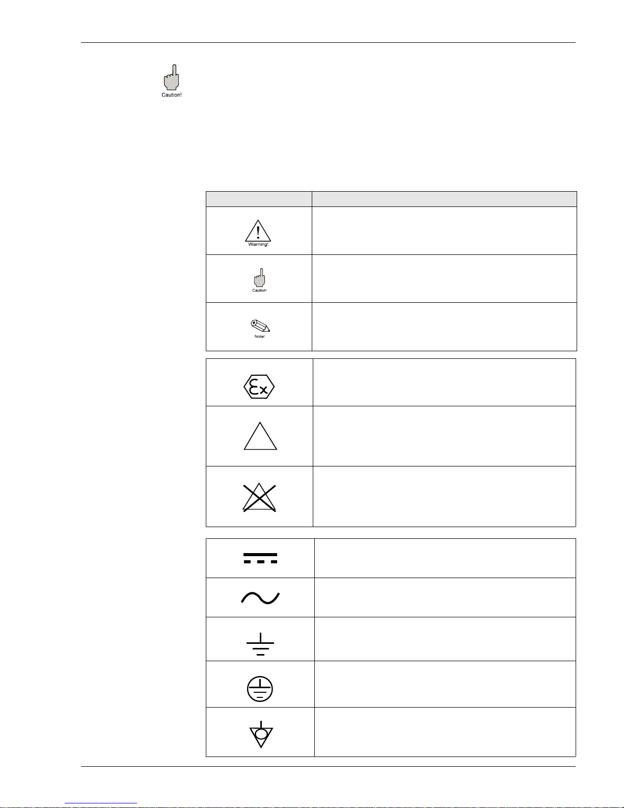
1.5 Notes on safety conventions and symbols
In order to highlight safety-relevant or alternative operating procedures in the manual, the
following convent ions have been u sed, each in dicate d by a corr esp onding symb ol in the m argin.
Protection from line noise.
Symbol Meaning
Warning
A warning highlights actions or p roc edur es w hich, if not performed
correctly, will lead to personal injury, a safety hazard or destru cti on
of the instrument.
Caution!
Caution highlights actions or procedures which, if not performed
correctly, may lead to personal injury or incorrec t func tionin g of the
instruments.
Note!
A note highlights actions or procedures which, if not performed
correctly, may indirectly affect operation or may lead to an
instrument respo nse whi ch is not planne d.
Device certified for use in explosion hazardous area
If the Micropilot h as this sy mbol emb ossed on i ts name pla te it can
be installed in an explosion hazardous area.
Explosion hazardous area
Symbol used in drawings to indicate explosion hazardous area.
- Devices located in and wir ing enteri ng are as with th e design ation
"explosion hazar dou s ar ea s" mu st conform with the stated type of
protection.
Safe area (non-explosion hazardous area)
Symbol used in drawings to indicate, if necessary, non-explosion
hazardous areas.
- Devices located in safe areas still require a certificate if their
outputs run into explosion hazardous areas.
Direct voltage
A terminal to which or from which a direct current or voltage may
be applied or supplied
Alternating voltage
A terminal to which or from which an alternating (sine-wave) curren t
or voltage may be applied or supplied
Grounded terminal
A grounded terminal, whi ch as far as the ope rator is con cerned, is
already grounded by means of an earth grounding system.
Protective grounded (earth) terminal
A terminal which must be connected to earth ground prior to
making any other connection to the equipment.
Equipotential connection (earth bonding)
A connection made t o the plant gro unding syste m which may be of
type e.g. neutral star or equipotential line according to national or
company practice
EX
EX
Explosion protection
Safety conventions
Electrical Symbols
1 Safety instructions
Page 6
Prothermo NMT 538
6 Endress+Hauser Systems & Gauging
2 Identification
2.1 Device designation
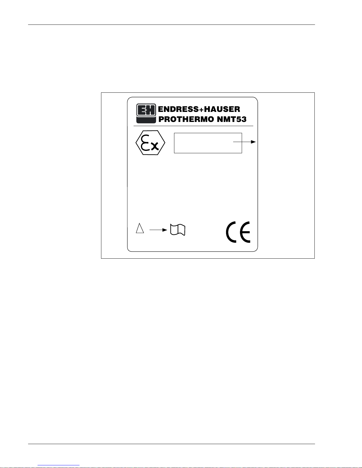
2.1.1 Nameplate
The follow technical data are given on the instrument nameplate:
8
Supply Circuit:
Ui < 30 V Ii < 120 mA Pi < 1W
Ci = 5.3 nF
Li = 0.2 mH
Temperature measurement circuit:
Uo = 11.3V
Io = 81.6 mA
Po = 406 mW
Ri = 404Ω Co = 0.22 µF
Lo = 4.0 mH
Sakura Endress Co.,Ltd.
Tokyo Japan
NP-2455
Type of Ex & IS
certification attached
Ambient Temperature: -20 ~ +60 C
!
i
2 Identification
Page 7
Prothermo NMT 538
Endress+Hauser Systems & Gauging 7
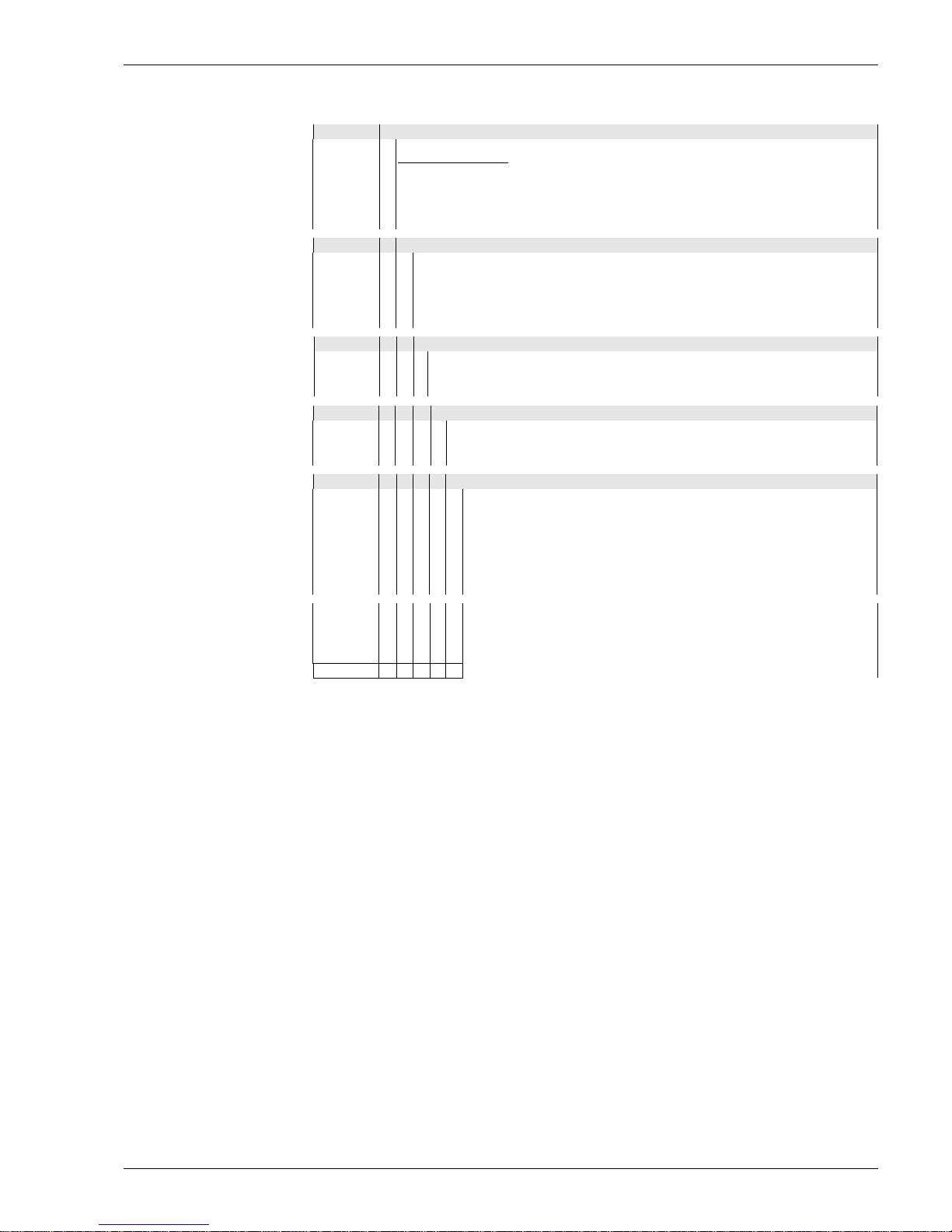
2.1.2 Ordering structure
10 Protection class
0 Protection: Weather proof IP 54
2 EEx ia IIB T4, CENELEC...obsolete, Nov. 2002
3 EEx ia IIB T4, ATEX
7 IS Class 1, Div 1, Gp, CD, FM
8 Class 1, Div 1, Gp, CD, CSA(Exi).....pending
9 Special version
20 Cable Entry
A One G(PF) 1/2" thread
B One NPT 1/2" thread
C One PG 16 Thread
D One M 20 thread
Y Special version
30 Process connection, material
1 3/4" NPS, Galvanized. mild steel
2 M20, Varec 1700 probe connection only, mild steel
9 Special version
40 Measuring range
1 Range: -50.....+200 °C (-58°F.....+392°F) liquid/gas temp. only
2 Range: -50.....+200 °C (-58°F.....+392°F) liquid/gas temp. and WB
9 Special version
50 Compatible Element Type
0 Cu90, multi resistance element
1 CuPt100, multi resistance element
2 Cu90, multi spot element
3 Pt100, multi spot element
4 Cu100, multi resistance el em en t
5 Cu100, multi spot element
9 Special version
NMT538- Complete product designation
2 Identification
Page 8

Prothermo NMT 538
8 Endress+Hauser Systems & Gauging
2.1.3 Specifications
Accuracy of conversion ±0.15 °C
Number of connectable elements 2...16
Conversion temp. range -50...+200 °C
Data communication M ul tidrop HART Protocol
Polling addres s: 02 for connectin g to Proservo NM S 53x
or Tank Side Monitor NRF590 (factory default value)
Input Level data, operation, & configuration command from
the NMS 53x Pros ervo or Tank Side Monitor NRF 590
Output Liquid level regarded various temp. data & element
information
Materials Housing: Aluminium diecast
Process connection: Galvanized carbon steel
Power supply DC24V ±10% from Proservo NMS 53x IS HART line
DC17 ± 1V from NRF 590 IS HART line
Power supply range: Requires DC16-30V for normal
operation condition
Current consumption 9mA ±0.5mA for signal pulse reception
Cable entry G (PF) ½ x 1
NPT ½ x 1
PG 16 x 1
M20 x 1
Ambient temp. -20...+60 °C (W. heating jacket option: -40...+60)
Certification Weather proof IP54
EEx ia IIB T4, CENELEC... obsolete
EEx ia IIB T4, ATEX
IS class 1, Div 1, Gp.CD, FM
Class 1, Div 1, Gp.CD, CSA...pending
2 Identification
Page 9

Prothermo NMT 538
Endress+Hauser Systems & Gauging 9
3 Installation
3.1 Incoming acceptance, transport, storage
3.1.1 Incoming acceptance
Check the packing and contents for any signs of damage.
Check the shipment, make sure nothing is missing and that the scope of supply matches your
order.
3.1.2 Transport
Caution!
Follow the safety instruction s and transp ort conditions fo r instrument s of mor e than 4 kg. Do not li ft
the measuring instrument by its housing in order to transport it.
3.1.3 Storage
Pack the measuring inst rument so that is protect ed against impacts for storag e and transport. The
original packing material provides the optimum protection for this.
The permissible storage temperature is -20°C...+60°C (-4°F...+140°F)
3 Installation
Page 10
Prothermo NMT 538
10 Endress+Hauser Systems & Gauging
3.2 Installation conditions
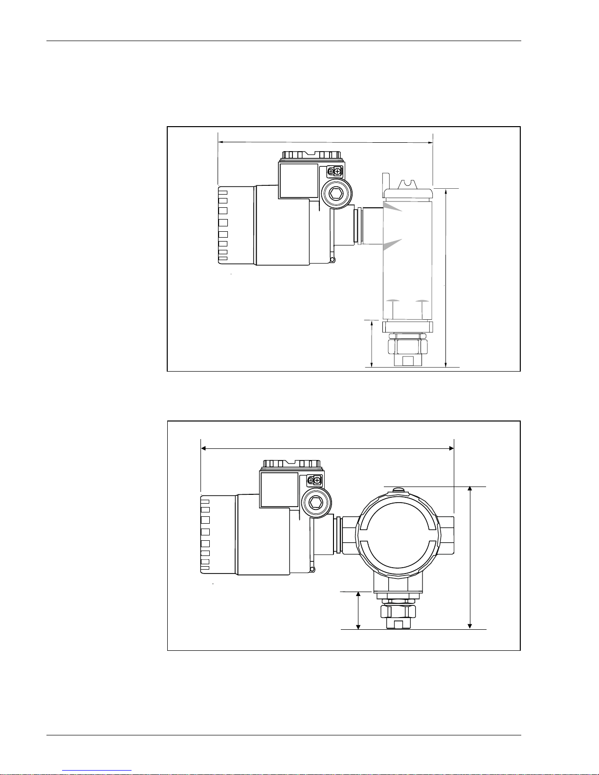
3.2.1 Dimensions
Figure1: Dimension & appearance of temperature version housing
Figure2: Dimension & appearance of temperature and WB version housing
Approx. 250 mm
225 mm
52 mm
Approx. 317 mm
198 mm
49 mm
3 Installation
Page 11
Prothermo NMT 538
Endress+Hauser Systems & Gauging 11
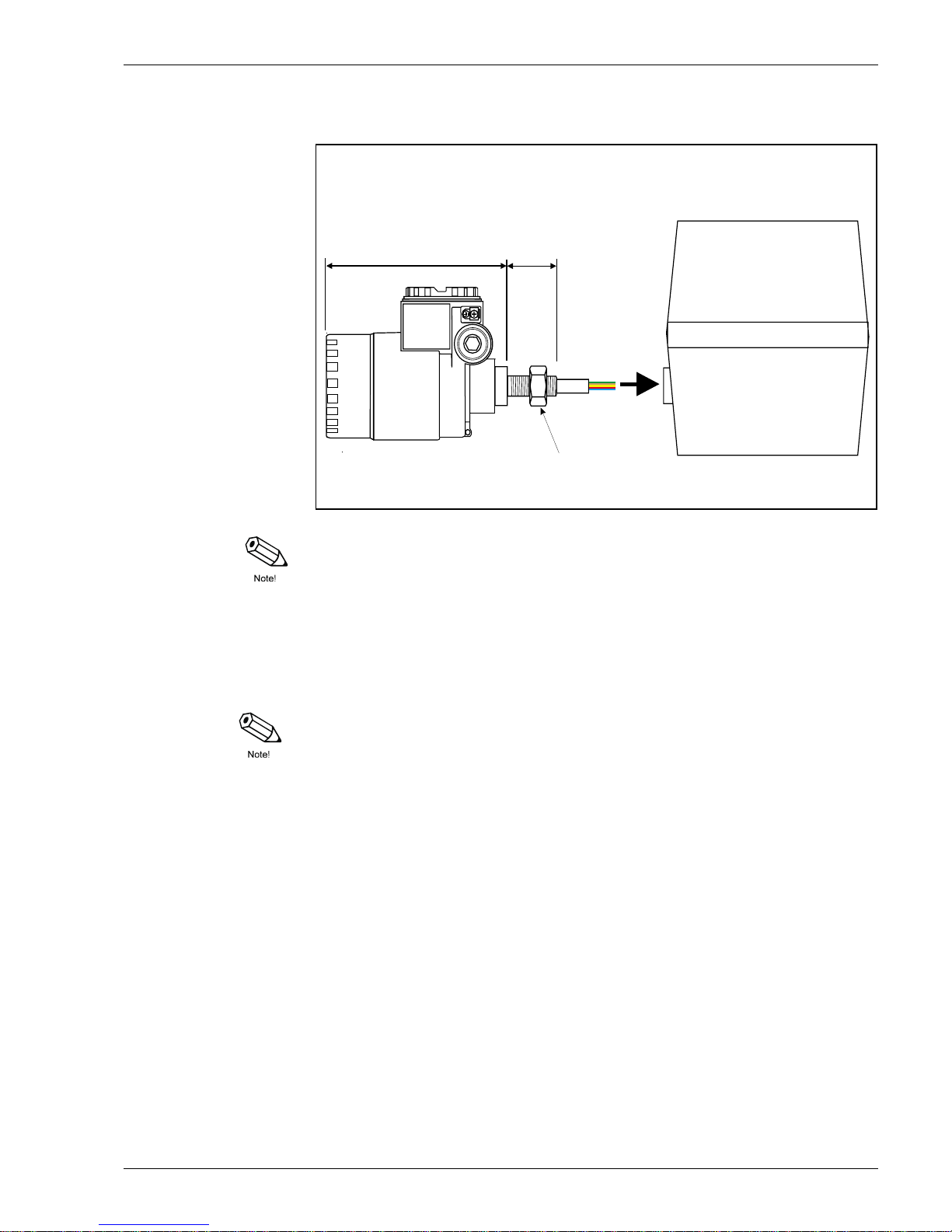
Figure3: Dimension & app earance of UK Special versio n (connection to 1700 se ries average
RTD probe only)
Note!
UK Special is only designed to connect with Whessoe Varec 1700 series average temperature
probe. WB data accessibility is no longer available at the NMT 538 prothermo.
Mounting of UK Special version M20 connection to Varec 1700 terminal box
Use seal tape on the threaded gauge to terminal box connection. Slip in a bunch of cable (RTD
signal inlet cable) into the terminal bo x female thre ad connection. Turn the entire NMT 538 gauge
head clockwise and screw in the connection at lea st 10 complete turns, then secur e with lock nut
against terminal box.
3.3 Mounting
3.3.1 Mechanical connection
Note!
Prior to the removal of existing RTD temp. converter, note following information, also these
information are applicable for new installations as well.
1. Element type (material & structure)
2. Total element number
3. Presence of bottom & vapor spot elements
4. Lowest element position
5. Elements intervals
6. Cable color for each element
Prior to perform NMT538 installation, temporarily tie up all RTD cables (and coaxial cable if the
probe is equipped with Water Bottom sensor) with zip tight or short string to avoid damaging
cables during mechanical connection.
168mm
32mm
Terminal Box of
1700 series RTD probe
Lock nut
3 Installation
Page 12
Prothermo NMT 538
12 Endress+Hauser Systems & Gauging
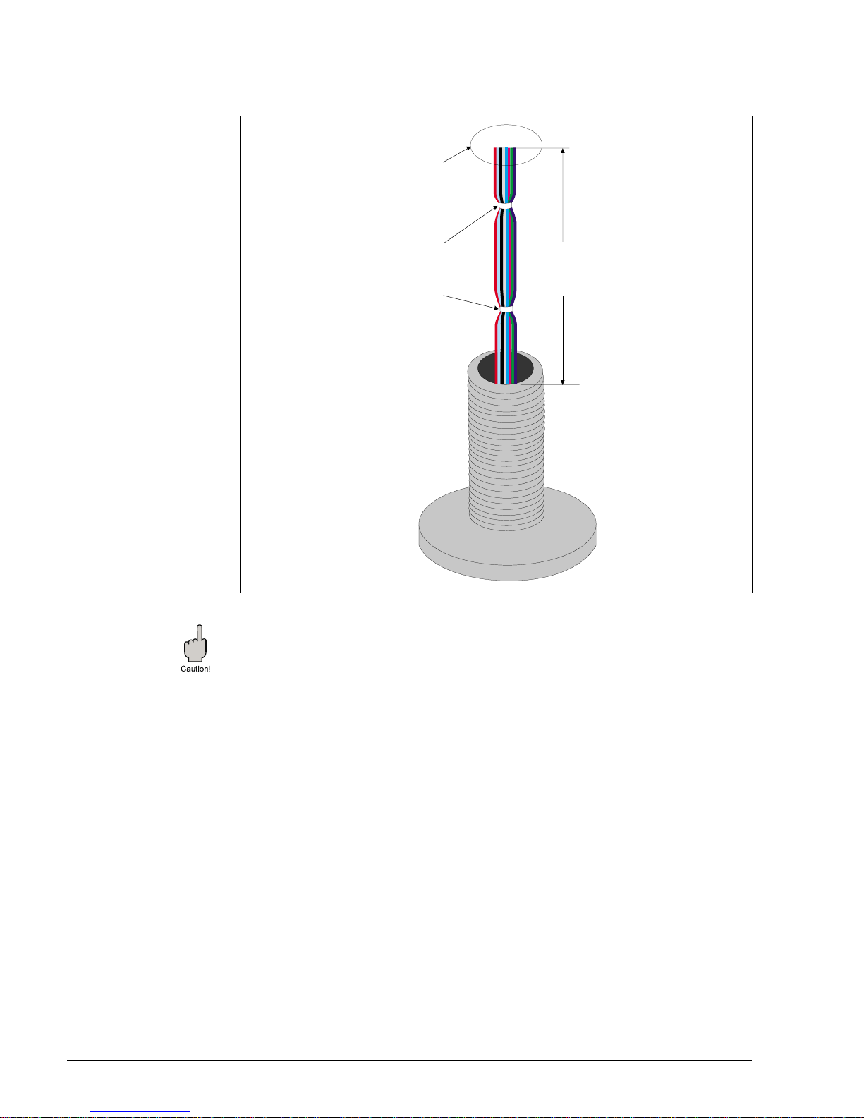
Figure4: Preparation to the mechanical connection
Caution!
Precaution before NMT538 mechanical installation is performed to the existing RTD probe.
Unscrew lower NPS threaded female connector once and try to fit on the temp. RTD probe to
ensure the each threaded connection can be smoothly attached.
Temporar y tie all cables
to avoid damaging with the
mechanical connection
Leave as much cable
length as possible
(Min. 250mm, or 10")
Trim cable ends
to the same length
for the NMT538
connection
3 Installation
Page 13
Prothermo NMT 538
Endress+Hauser Systems & Gauging 13
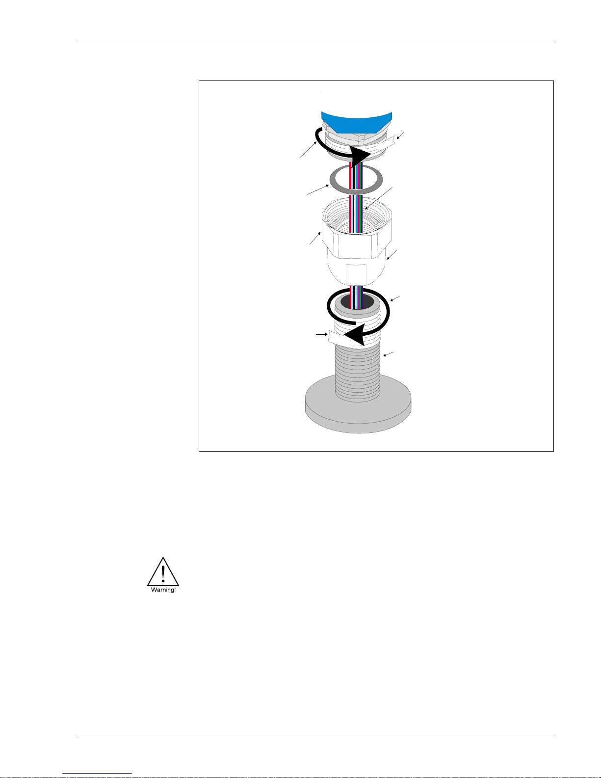
Figure5: Threaded type connection
1. Install lower NPS threaded female connector along with free spinning coupling onto RTD
probe threa ded con nectio n unti l it i s com pletel y seated. Use a se al tape and ra p it around on
the RTD probe’s threaded connection .
2. Install NMT538 housing along with included gasket in-between. Use a seal tape and rap it
around on the NMT538 housing side male threaded connector, then hand tight the free spinning coupling until it stops.
3. Remove the cap cover and m ake s ur e the both side of ca ble s h av e e nou gh len gth to be connected freely.
warning!
Do not pull either side cables or apply over-tension during this procedure. Internally torn cables
or loose connection can cause invalid temperature measurement.
4. After performing cable connection & positioning the face angle of NMT538, Tighten approximately 1/8th turn the free spinning coupling with a wrench from where it was hand tighten.
3.3.2 Wiring: NMT538 to RTD probe
Temperature signal cables
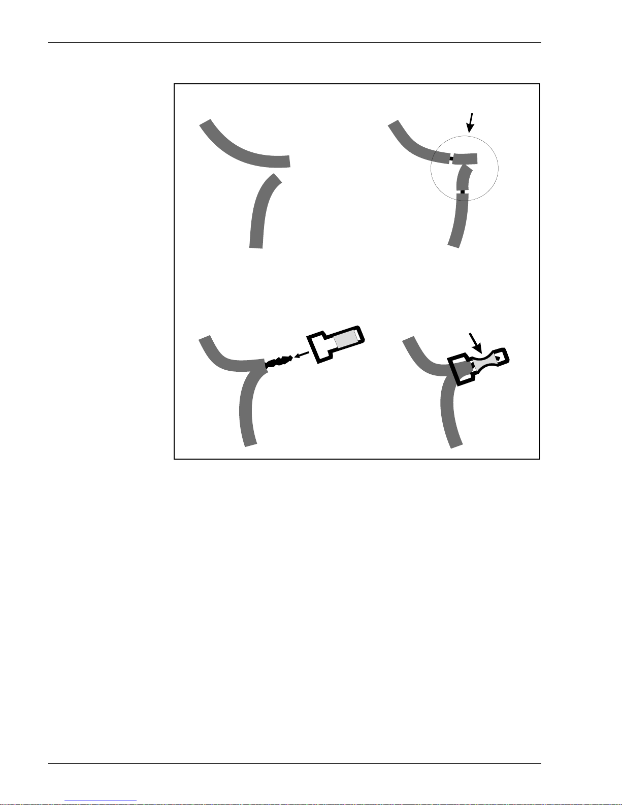
RTD cables will be directly connected to NMT538 input cables with simple cramp connectors
(included). Strip each end of cable approximately 1cm (3/8") and slip into the connector, then
pinch with pliers to secure the connection.
NMT538
Seal tape
(not included)
Seal tape
(not included)
T
ape winding
rotation
Tape winding
rotation
Gasket
(included)
Free spin
coupling
NPS 3/4
threaded connection
(RTD probe side)
to Average temp. element
RTD signal &
(WB capacitance coaxial)
cable from
Lower NPS threaded
female connector
probe
3 Installation
Page 14
Prothermo NMT 538
14 Endress+Hauser Systems & Gauging
Figure 6: Connector details
Cabling color code is listed below.
NMT 538 cable color: the principl e Based on the same as A,B,b 3 wire sp ot RTD cabli ng method.
A: Signal wires
No.1: brown (lowest position)
No.2: red
No 3: orange
No. 4: yellow
No. 5: green
No. 6: blue
No. 7: violet
No. 8: gray
No. 9: white
No. 10: pink
No. 11: brown / black
No. 12: red / black
No. 13: orange / black
No. 14: yellow / black
No. 15: green / black
No. 16: blue / black
B: Common wires
B0: gray / black
B1: violet / black
b: white / black
cable from
NMT538
cable from
RTD probe
1. Select a pair cables
A cable from
NMT538
A cable from
RTD probe
2. Strip cable ends
approximately 10mm, or 1/2"
A cable from
NMT538
A cable from
RTD probe
3. Twist both ends together
and install terminal connector
A cable from
NMT538
A cable from
RTD probe
4. Cramp the connected terminal
with pliers or any connector tool
3 Installation
Page 15
Prothermo NMT 538
Endress+Hauser Systems & Gauging 15
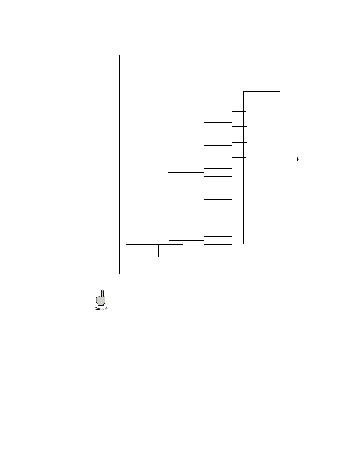
Diagram 1: NMT538 with Whessoe 1700 & Varec 9909
Standard NMT538 to average probe connection
Caution!
Some RTD probes are equipped with additional bottom and vapor spot bulb besides average
temp element. Unless a probe has these spot elements, connect brown to brown cables, red to
red cables accor din g to diagram 2. Do not skip us ing bro wn (No. 1 element) o n the NMT5 38 side
input cables. Not connected to #1 brown wire on NMT538 input will cause open circuit error
(displaying 359°C) constantly.
No.16
No.15
No.14
No.13
No.12
No.11
No.10
No.9
No.8
No.7
No.6
No.5
No.4
No.3
No.2
No.1
B Ø, B
b
yellow & black
green & black
blue & black
orange & black
red & black
brown & black
No.10 (pink)
black
No. 9 (white)
white
No. 8 (gray)
gray
No. 7 (violet)
violet
No. 6 (blue)
blue
No. 5 (green)
green
No. 4 (yellow)
yellow
No. 3 (orange)
orange
No. 2 (red)
red
No. 1 (brown)
brown
white & black
gray & black
black
black
Cables from
Whessoe 1700
Varec 9909
Temperature Probe
from the tank
cables from
NMT538 module
cramp
connection
to NMT538
electronics
Connection in the NMT538 Terminal Housing
violet & black
3 Installation
Page 16
Prothermo NMT 538
16 Endress+Hauser Systems & Gauging
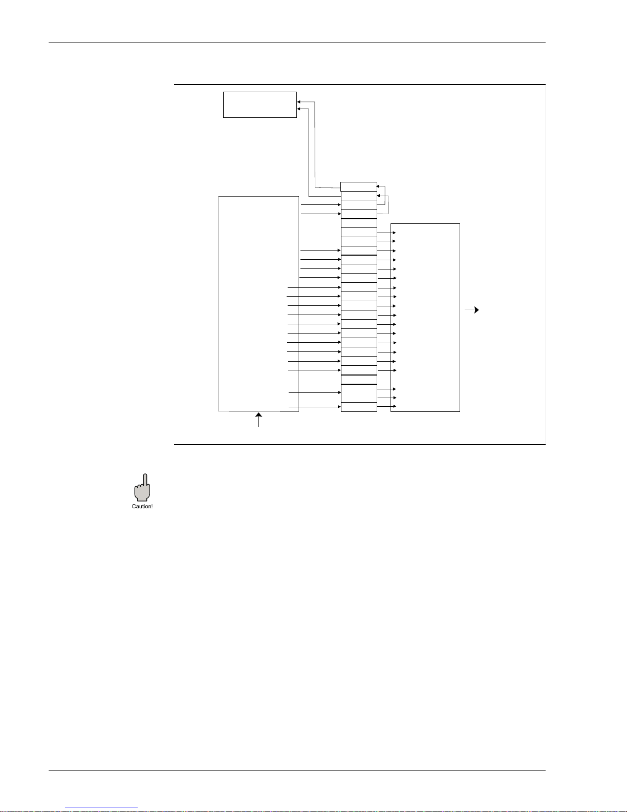
Diagram 2:NMT538 with Weed Beacon MWR type with Water Bottom sensor
caution!
RTD probe side cables color ma y differ fr om diagram above . Note the conne ction and cable c olor
combination during disassembling previous RTD temperature converter. This will prevent faulty
element to converter connection.
Uneven cable length can influence the precise temperature calculation to be inaccurate result.
Trim cable end to the even length as much as possible in case of uneven cabling condition
presents at the RTD probe side cables.
Coaxial cable for capacitance signal to auxiliary converter
NMT538 temp. + WB version allows accessibility of coaxial cable (Water Bottom capacitance
signal) from the auxiliary capacitance to HART converter (DREXELBROOK and others). The
sensor cable from WB probe and converter cable through cable outlet can meet within NMT538
terminal housing or sensor ca ble can direct ly exit from cabl e outlet. Some WB capac itance sensor
might have additional gr ound wi re. Please route t his wir e to the existing C V converter ac cordingly
without interruption inside of the NMT 538 housing.
WB out
WB out
WB in
WB in
No .16
No .15
No .14
No .13
No .12
No .11
No .10
No . 9
No . 8
No . 7
No . 6
No . 5
No . 4
No . 3
No . 2
No . 1
BØ,B
b
No.14 (white & yellow)
yellow & black
green & black
blue & black
No.13 (white & orange)
orange & black
No.12 (white & red)
red & black
No.11 (white & brown)
brown & black
No.10 (pink)
black
No. 9 (white)
white
No. 8 (gray)
gray
No. 7 (violet)
violet
No. 6 (blue)
blue
No. 5 (green)
green
No. 4 (yellow)
yellow
No. 3 (orange)
orange
No. 2 (red)
red
No. 1 (brown)
brown
white & black
violet & black
black
black
CAPACITANCE (+)
to auxiliary
capacitance converter
CAPACITANCE (-)
+
_
cables from
Weed Beacon
MW or MWR type
temp. & WB probe
from the tank
to NMT538
electronics
cables from
NMT538 module
cramp
connection
connection in the
NMT538 terminal housing
(temp. & WB version)
gray & black
3 Installation
Page 17
Prothermo NMT 538
Endress+Hauser Systems & Gauging 17
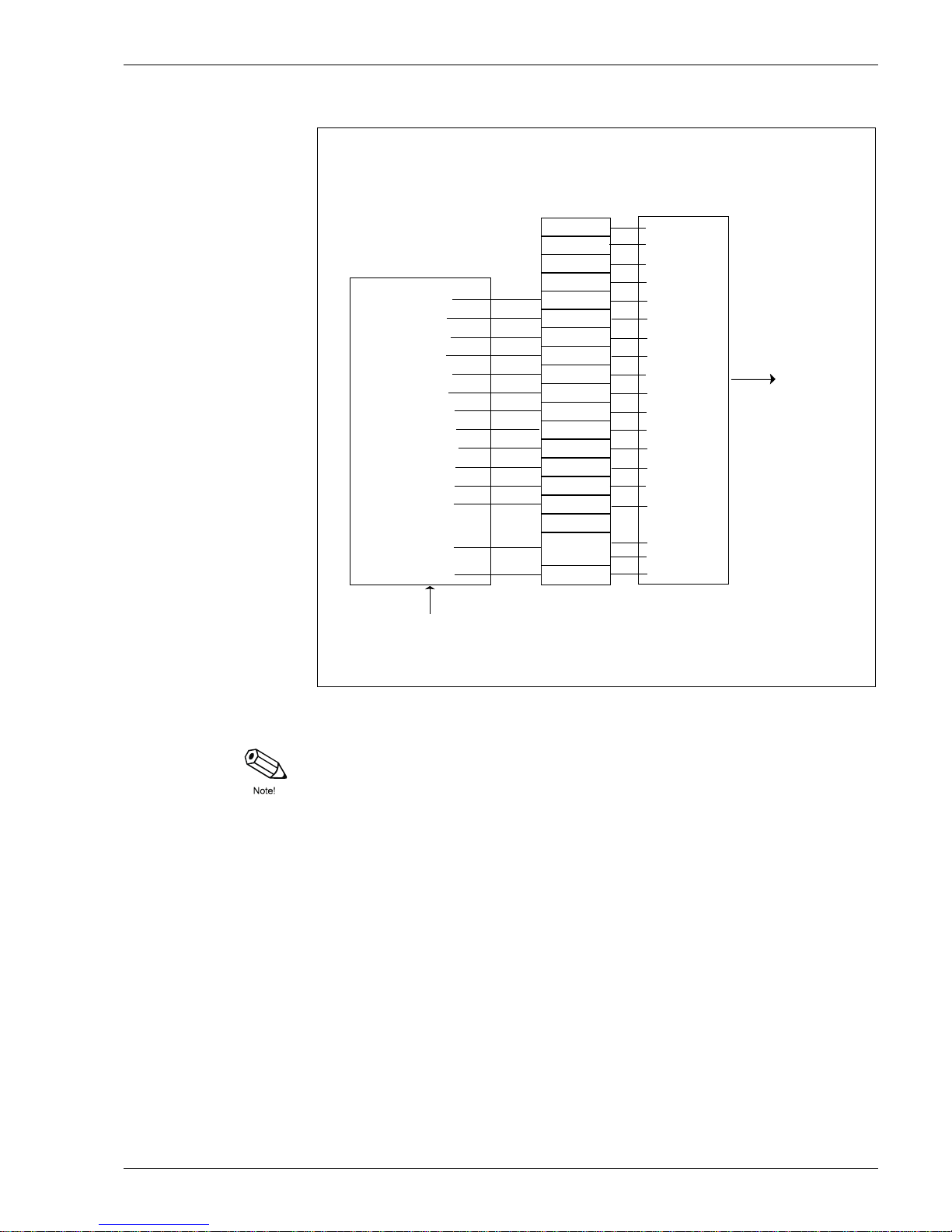
Diagram 3: NMT538 with Varec 9909 with bottom & vapor spot temperature
Note!
Since NMT538 is capable of accepting up to 16 elements for average temperature calculation,
the bottom & vapor spot elements can be used to expand its measuring range. In this case, the
bottom spot can be used as the #1 lowest position element for the connection to the brown wire
from the NMT538. If the average elements have already 16 input, ignore connecting neither the
bottom nor vapor spot element.
No.16
No.15
No.14
No.13
No.12
No.11
No.10
No.9
No.8
No.7
No.6
No.5
No.4
No.3
No.2
No.1
B Ø, B
b
yellow & black
green & black
blue & black
orange & black
red & black
brown & black
No.10 (pink)
black
No. 9 (white)
white
No. 8 (gray)
gray
No. 7 (violet)
violet
No. 6 (blue)
blue
No. 5 (green)
green
No. 4 (yellow)
yellow
No. 3 (orange)
orangeNo. 2 (red)
red
No. 1 (brown)
Bottom Spot
Vapor Space Spot
brown
white & black
gray & black
black
black
cables from
Varec 9909
Temperature Probe
from the tank
cables from
NMT538 module
cramp
connection
to NMT538
electronics
Connection in the NMT538 Terminal Housing
violet & black
3 Installation
Page 18
Prothermo NMT 538
18 Endress+Hauser Systems & Gauging
3.4 HART line cabling
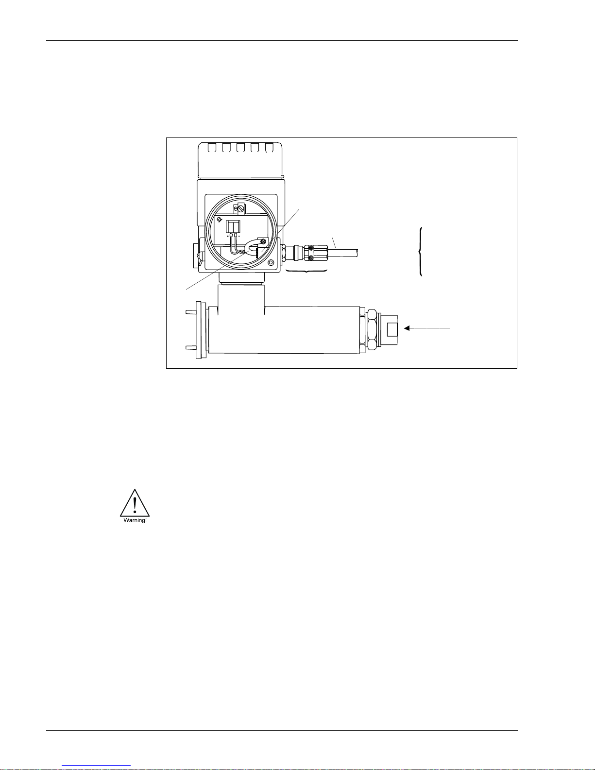
NMT538 is a HART slave instrument. that requires power supply for the device operation and
communication signal on the same 2 cables.
Figure 7:NMT 538 terminal board
Required DC voltage for NMT538 operation is minimum 16 to maximum 30 volt.
With the connection to the Proservo NMS53x, normally supply DC24V ±10% to the NMT 538. Th e
Tank side monitor NRF590 can normally supply DC16±1V on the IS HART loop.
Both the NMT538 and host instrument recognizes 0.5mA current shift as the trigger of data
transmission. I.e, NMT538 normally consumes 9.0mA at temperature measurement only. The
current consumption decreases to approximately 8.5mA while NMT538 is receiving command
from the host gauge on the HART line. On the other hand, the current consumption increases to
approximately 9.5mA while NMT538 is sending data to the host gauge as a response to the
previous command.
Warning!
Before opening the cover of th e Prothermo NMT 538 for maintena nce, switch of f the power suppl y
of the Proservo NMS53x or the Tank side monitor NRF590. Eit her of th ese 2 inst rument s normally
are the host gauge to supply DC voltage on the IS HART line to the NMT538.
3.4.1 Protection from line noise
The following precautions are required to rule out any malfunction by line noise.
-The minimum conductor size for the HART transmission distance up to 1500m should be used
0.51mm diameter (#24 AWG) shie ld twisted pair cabl e and 0.81mm diamet er (#20AWG) for longer
distance.
-Use appropriate cable size reference to the conditions described below chart 1.
Grounding for cable screen
Screened twisted pair
or steel armored wire
Temp.HART
from NMT 538
+ terminal 1
- terminal 2
to NRF 590
+ terminal 24 or 26
- terminal 25 or 27
to NMS53...
+ terminal 24
- terminal 25
Cable gland
(Refer to specifications)
Temp. RTD signal (max. 16 points)
- Whessoe Varec 1700
- Whessoe Varec 9909
- Weed Beacon MW & MWR
FG
1 2
Screen
3 Installation
Page 19
Prothermo NMT 538
Endress+Hauser Systems & Gauging 19
Chart 1: Typical cable capacitance & distance for 1.02mm (#18 AWG) shield twisted pair
-If you use an unscreened wire, then equip it with a conduit pipe.
-Connect the cable screen to the frame ground.
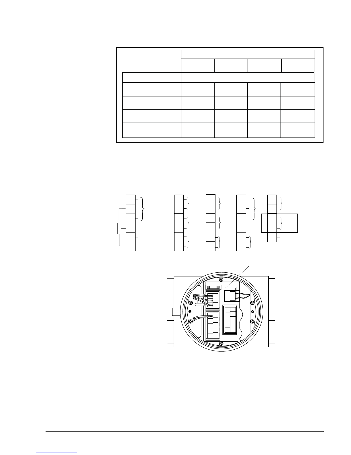
3.4.2 Connection to the Proservo NMS53x
Figure 8: Terminal connection on the Proservo NMS
Tank sensors
The Proservo NMS53x can interface up to 4 HART sensors. All HART sensors are connected to
one HART multi-drop communication loop internally. In order to separate IS and non-IS HART
sensory connection, 2 pairs of HART terminals are equipped on the Proservo NMS53x. The
NMT538 can be connected only on terminals 24(+) & 2 5(-) where the IS HART module i s installed.
Cable Capacitance - pf / m (pf / ft)
65 pf / m 95 pf / m
160 pf / m 225 pf / m
(20 pf / ft)
(30 pf / ft)
(50 / pf / ft)
(70 pf / ft)
NO. Network Devices Cable length - meters (feet)
2763 m
2000 m 1292 m
985 m
(9000 ft)
(6500 ft)
(4200 ft) (3200 ft)
5
2462 m 1815 m
1138 m 892 m
(8000 ft)
(5900 ft)
(3700 ft) (2900 ft)
1
10
2154 m 1600 m
1015 m
769 m
(7000 ft)
(5200 ft) (3300 ft)
(2500 ft)
1846 m
1415 m 892 m
708 m
(6000 ft)
(4600 ft) (2900 ft)
(2300 ft)
15
4 ... 20 mA
4 ... 20 mA
Channel 1
Channel 2
Port_A+
Port_A-
IS HART
or
+
+
_
_
A
B
b
22
23
24
25
26
+
_
COM
HOIST
STOP
Operation
contact
input
20
21
16
19
18
17
Alarm contact
Alarm contact
Alarm contact
+
_
+
_
+
_
10
15
14
13
12
11
Alarm contact
+
_
Port_B-
Port_B+
Non IS HART
to NRF or others
+
_
9
8
7
6
5
4
Power supply
AC 85 ... 264V 50/60Hz
or
DC 20 ... 62V AC20 ... 55V
2
3
1
G
N
L
L
G
N
ARS
ARS
ARS
+
_
Digital output
Rack bus RS485,
Serial pulse,
or
HART
1
2
3
ARS
ARS
ARS
L
N
GND
L
G
N
46
8
10
12
5
7
9
11
13
NRF
+
NRF-
RC
A/+
RC
B/-
AL1
AL1
AL2
AL2
AL3
AL3
14
16
18
22
15
17
19
21
23
AL4
AL4
COM
CTR1
CTR2
N.C.
OT1-
OT1+
OT2-
OT2+
20
24
26
25
P_A+
A
P_A-
B
b
From NMT 538
3 Installation
Page 20
Prothermo NMT 538
20 Endress+Hauser Systems & Gauging
Caution!
NMT538 HART co nnecti on can be onl y all owed when th e P ros ervo NM S53x is eq uipped with the
intrinsically safe HART input module. The connection is not allowed when the built in spot
temperature input is selected on the Proservo NMS.
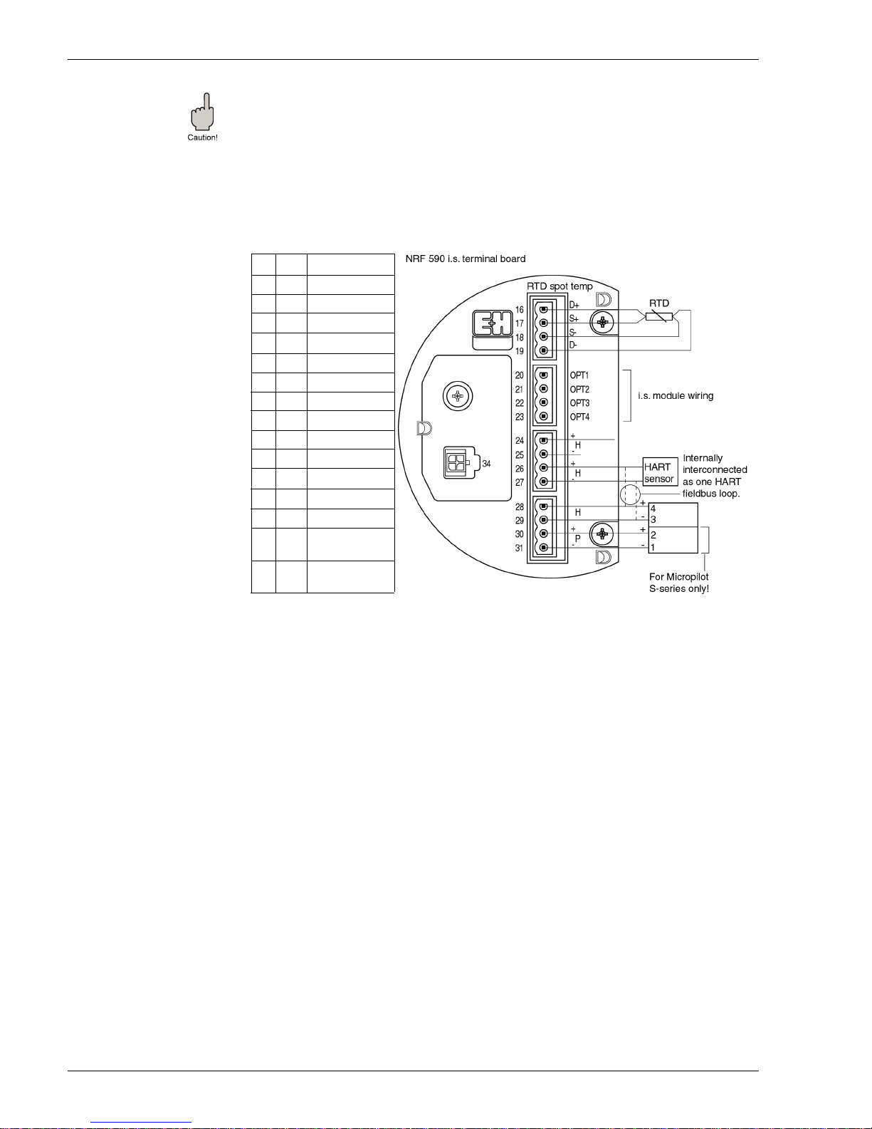
3.4.3 Connection to the Tank side monitor NRF590
Figure 9: Terminal connection on the tank side monitor NRF590
Ta nk sens ors
The Tank side monitor NRF590 can interface up to 6 IS HART sensors. All HART sensors are
connected to one HART multi-drop communication loop. To keep the wiring simple, 3
interconnected t erminal pairs ar e avai lable; ho wever, 2 pairs of terminals, 24(+) 25(-) & 2 6(+) 27(), are available for the NMT538 con nectio n since terminals 28(+) 29(-) ar e r eserv ed for the Micr o
pilot S FMR 53x HART connection.
16
D+ + RTD drive
17
S+ + RTD sense
18
S- - RTD sense
19
D- - RTD drive
20 OPT1 i.s. OV
21 OPT2 4...20 mA input
22 OPT3 i.s. OV
23 OPT4 i.s. +24V
24 H+ + Hart comm.
25 H- - Hart comm.
26 H+ + Hart comm.
27 H- - Hart comm.
28 H + Hart comm.
29 H - Hart comm.
31 P-
+ i.s. power for FMR
S-series (terminal 1)
30 P+
- i.s. power for FMR
S-series (terminal 1)
4 Operation Principle
Page 21
Prothermo NMT 538
Endress+Hauser Systems & Gauging 21
4. Operation Principle
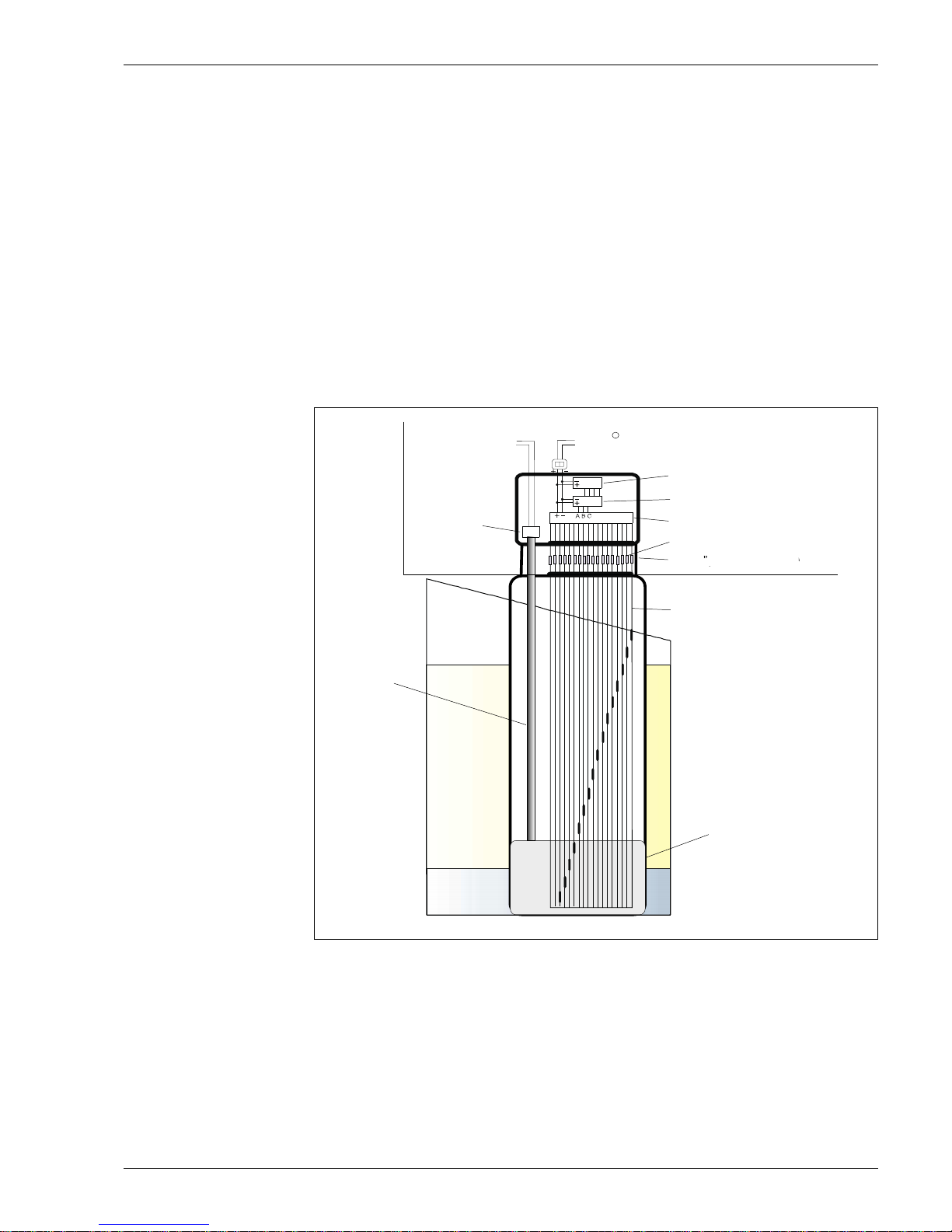
4.1 High Accuracy Converter
The Prothermo NMT538 temperature signal converter is designed to fit on existing foreign RTD
average temperature probe to Endress +Hauser HART compatible intelligent average
temperature measurement device. The RTD average temp. probe may consist of Cu90, Cu100,
PtCu100, & Pt100 m ulti-s pot an d/or mult i-r esist ance eleme nt. Th e Pr ot hermo N MT538 is cap able
of converting various RTD resistance input to intrinsically safe IS HART signal output. The liquid
and gas phase average temperature are determined based on liquid level data that is provided
by the Proservo NMS53x or FMR Micro pilot series radar gauge through Tank side monitor
NRF590. Maximum up to 16 individual in put can be arranged with either equal or un equal spaced
element intervals a r e selected. Also the a ddit ion al WB c onn ection feature allows the NMT 538 to
engage to the foreign water interface measurement probe with average temperature probe like
Weed beacon MW & MWR type, then provide accessibility of auxiliary capacitance converter.
Figure 10:Operating principle of NMT 538
Water bottom
signal out
process connection
NPS ¾
Scanning circuit
Amplifier
Calculation and
HART transmission circuit
Coaxial cable
connection
Gas
Coaxial cable
Oil
(upper layer liquid)
Capacitive probe
(Water bottom sensor)
Flexible tube
(Ex i compatible, sealed)
NMT 538
HART signal out
R
Water
(lower layer liquid)
RTD
signal in (up to 16 points)
Clamp connection
4 Operation Principle
Page 22
Prothermo NMT 538
22 Endress+Hauser Systems & Gauging
4.2 Temperature calculation
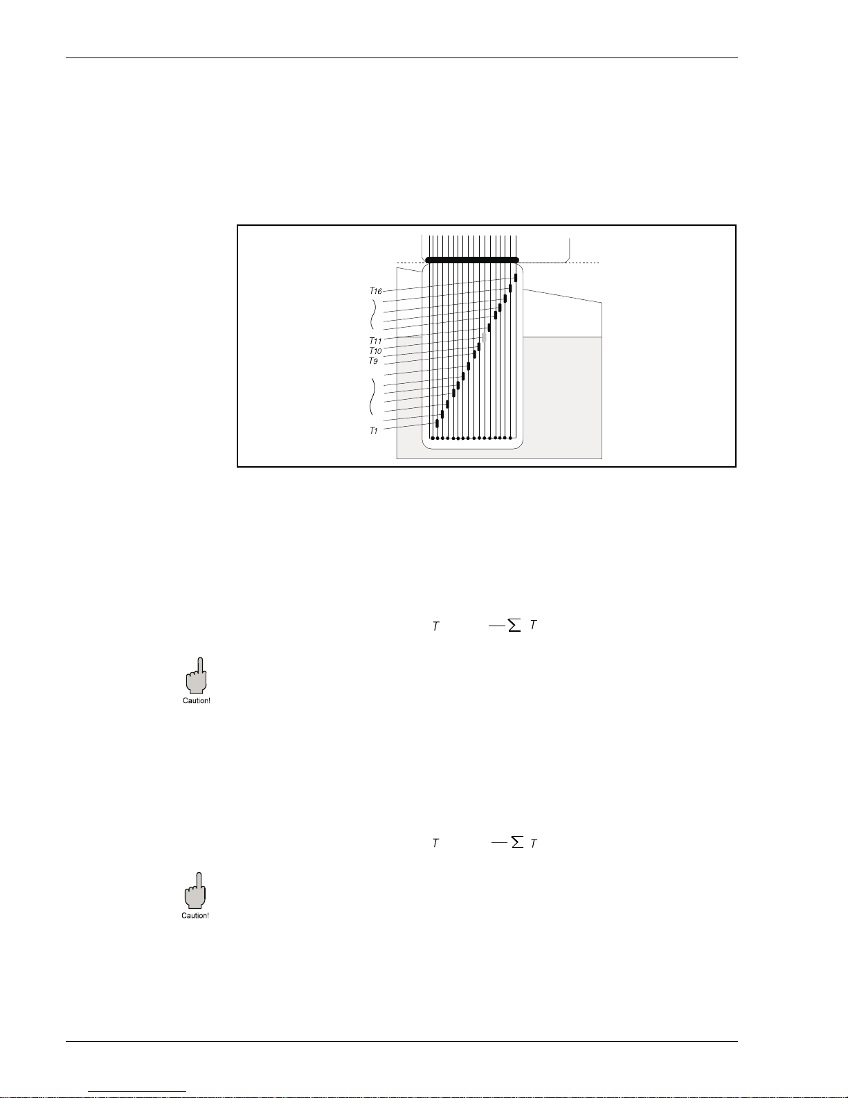
The NMT538 is able to calculate two separate (upper gas/ vapor layer and lower liquid layer)
average temperatures described below.
Typical calculation procedure with multi-spot element
Figure 11: Typical multi-spot element layout
• · T1,T2…T16 represent temperature data of multi-spot elements
• · The element T10 is consider ed exactly positio ning at the liquid level; the refore it is no t included
neither liquid nor gas average calculation based on terminology of Liquid & Gas offset.
4.2.1 Calculation of average temperature in the liquid layer
Tav, liquid Formula
Caution!
Liquid offset level
Elements to be included in liquid ave rage calcul ation sho uld be subm erged 300mm below liqui d
surface at the default setti ng. P lease contact with Endress + Hauser in case of changing "Liquid
offset level".
4.2.2 Calculation of average temperature in the gas / vapor layer
Tav, gas formula
Caution!
Gas offset level
Elements to be included in gas / vapor average calculation should be positioned 300mm above
liquid surface at the default setting. Please contact with Endress + Hauser in case of changing
"Gas offset level".
Canceling defected elements (pending function)
The NMT538 primarily sends out error message to the host gauge regardless of liquid level in
case of the defected element or/and cable present during the operation. The operator can
command the NMT538 to cance l defecte d element s to be o ut of c alculatio n purposel y by lim iting
gas/vapor average calculation disabled.
Gas
Liquid
Flexible
tube
av, liq
=
9
1
i =1
9
i
av, gas
=
6
1
i =11
16
i
4 Operation Principle
Page 23
Prothermo NMT 538
Endress+Hauser Systems & Gauging 23
5 Operation with the Proservo NM S53x
The NMT538 basi cally requires the host gauge to c ommand & init ializ e all re gar din g func tional ity
since it is the HART slave & data display free instrument. The NMT538’s operation procedure,
data acquisition method, and availability of function are depending on which host gauge is
connected to.
5.1 NMT538 operation with the Proservo NMS53x
Most of NMT538 functions are controlled & configured from the Proservo NMS53x matrix
operation. The communication between the NMT538 & Proservo NMS53x is predetermined with
specific polling add res s and pr otocol envir onment; theref ore , the minim um initi al set up would be
required in order to start up the gauge operation.
5.1.1 Home position display
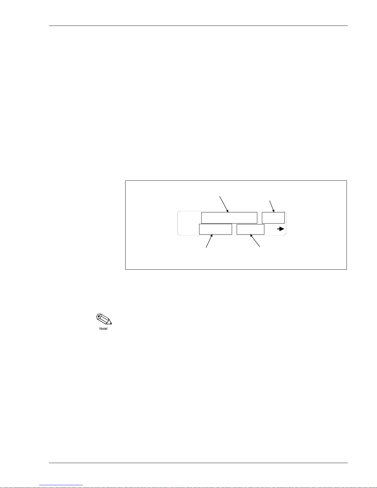
The Proservo NMS53x displays several data at the "Home Position" includes the average liquid
temperature data.
Figure 12: Home Position display
A: Liquid level, displays the last measured liquid level if the Proservo is in other operation.
B: Average liquid temperature, displays latest liquid average temperature.
C: NMS gauge status: displays type of the Proservo operation.
D: NMS displacer status: displays the status of displacer.
Note!
The Proservo NMS53x continuously scans and update the temperature data that transmits from
the NMT538 approximately every 2 seconds per 1 matrix data during the normal operation.
However, it takes approximately 3 minutes to display all NMT related data right after turning the
power supply from the NMS53x.
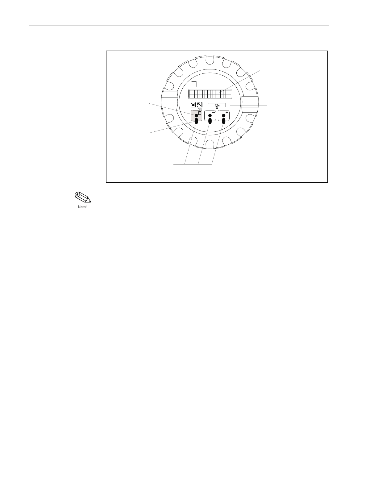
5.1.2 Optical key (touch control) operation
The operational structure of both the Proservo NMS53x & NMT538 are based on Endress +
Hauser matrix concept. The Proservo NMS53x utilizes 3 infrared key (non-mechanical switch),
namely E, -, +, for operation and configuration of all connected sensors includes the Proservo
NMS53x its elf by accessing each matrix.
1120.0mm BAL
65.5c : LIQU: E
B: A verage liquid
T
emp. data
C: NMS status
A: Liquid level
D: Displacer
status
5 Operation with the Proservo NMS53x
Page 24
Prothermo NMT 538
24 Endress+Hauser Systems & Gauging
Figure 13: NMS53x display module
Note!
The LCD will return to the Home position if no key is touched for more than 10 min.
Digits are incremented or decremented by + or - respectively. If you touch + or - continuously,
then the minimum di git will c hange firs t. After on e cycle of the m inimum, the second minimum will
change. After one cycle o f the second fol lows the third minimum, and so on. If you tak e your finger
from the touch control, then the procedure will start again from the minimum digit. (Analogy of
mechanical counter)
5.1.3 Access code
The purpose of the access code is to s ecure the install ed data. The re ar e thr ee secu rity levels f or
the functions of the Proser vo NMS53x.
Access code 0 (or no value entered): no security level
Access code 50: security level for operator
Access code 51: security level for engineer
Access code 777 special code for HART IS switch function
Based on the choice of access code, displaying matrix and operational functionality are also
variable.
Infrared
transmitting
diode
Infrared
receiving
diode
Three optical
operating elements
("touch control")
Illuminated LCD,
two lines with
16 characters each
Function symbols
(from left to right):
* Access to the
* Return to the
* Diagnostic function
programming matrix
HOME position
PROSERVO NMS531
5 Operation with the Proservo NMS53x
Page 25
Prothermo NMT 538
Endress+Hauser Systems & Gauging 25
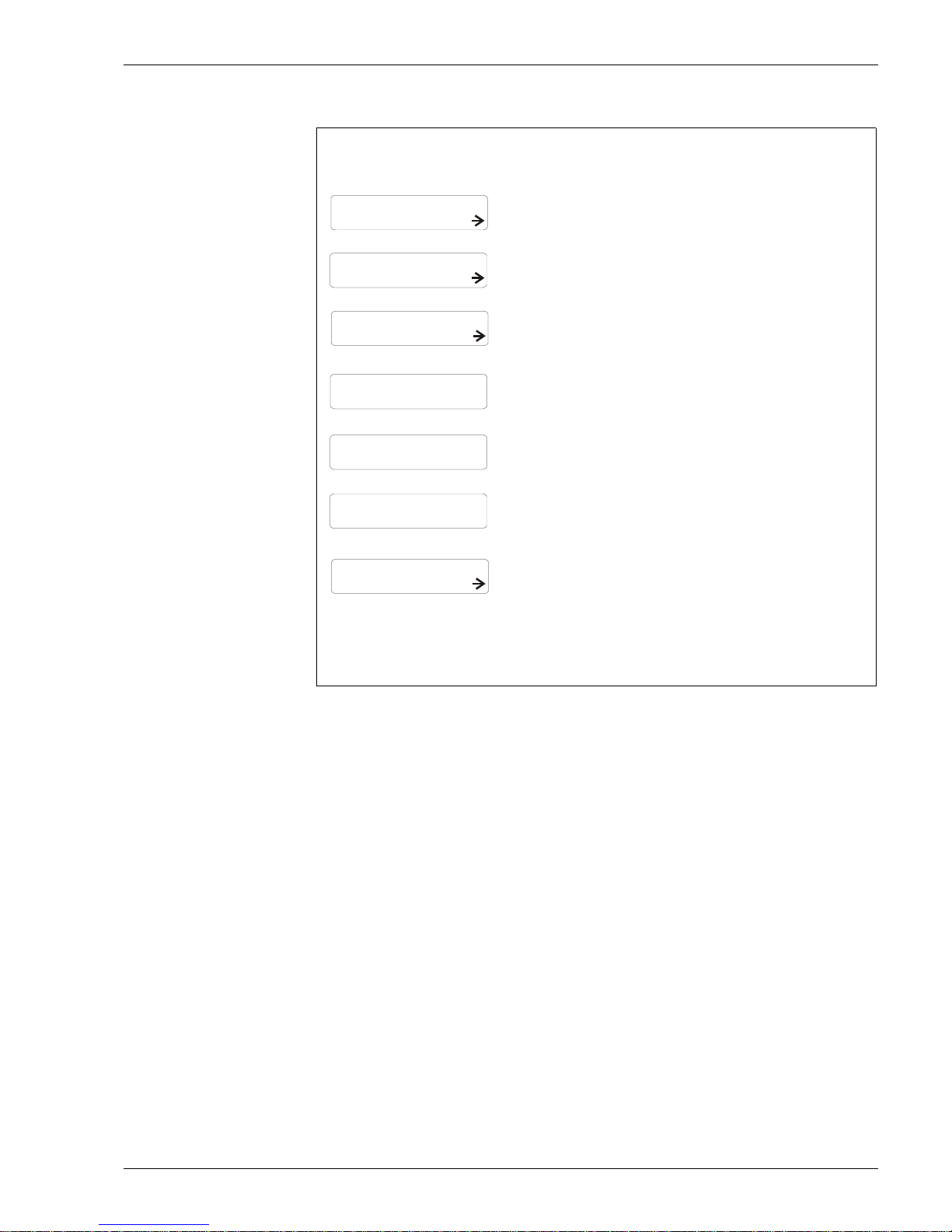
QOC1:Quick operation guide for setting an access code
5.1.4 Type of the Programming Matrix group
The row 0…3 of the programming matrix are called "Static Matrix". Its functionality is to display
and allow program ming of ma inly m easu red value (prima ry variable s) and basic oper ation of the
Proservo NMS53x and NMT538.
The row 4…9 exist on 9 different pages called as "Dynamic Matrix". These matrix groups are
labeled as follows.
G1: CALIBRATION
G2: DEVICE DATA
G3: SERVICE
G4: TEMPERATURE
G5: HART DEVICE (1)
G6: HART DEVICE (2)
G7: ADJUST SENSOR
G8: TANK PROFILE (NMS software ver. 4.25 only)
G9: INTERFACE PROFILE (NMS software ver. 4.25 only)
1120.0mm BAL
MEASURED VALUE 1
MORE FUNCTION
MORE FUNCTION
0
51
EDITING ENABLED
65.5c : LIQU: E
>GROUP SELECT<: E
>GROUP SELECT<: E
>GROUP SELECT<: E
ACCESS CODE
ACCESS CODE
Hold "E" key for more than 3sec.
Enter "+" key 3 times
Home position display
Now you are in the
G0 Static matrix
Note!
If you missed "MORE FUNCTION"
matrix, use "-" key to reverse.
If you missed "ACCESS
CODE" matrix, keep entering
with "E" til l n ex t cycle.
Other than 50, 51, or 777, display
will reply "EDITING BLOC KED",
correct code must be entered.
Access code confirmed
Now, it is ready for
further confi guration
Enter "E" key several times until
"ACCESS CODE" will appear
on the display.
Use "+" or "-" to set
desired access code (50, 51, 777)
Enter "E" to confirm, Access code
is now acquired.
Then, E nter "E" once to return
to "MORE FUNCTION"
in Static matrix
LCD display Procedure
Remark
5 Operation with the Proservo NMS53x
Page 26
Prothermo NMT 538
26 Endress+Hauser Systems & Gauging
5.1.5 Configuring the NMT538 on the matrix of Proservo NMS53x
To display NMT538 data and configure detailed parameters, the communication between these
2 instruments must be initially established.
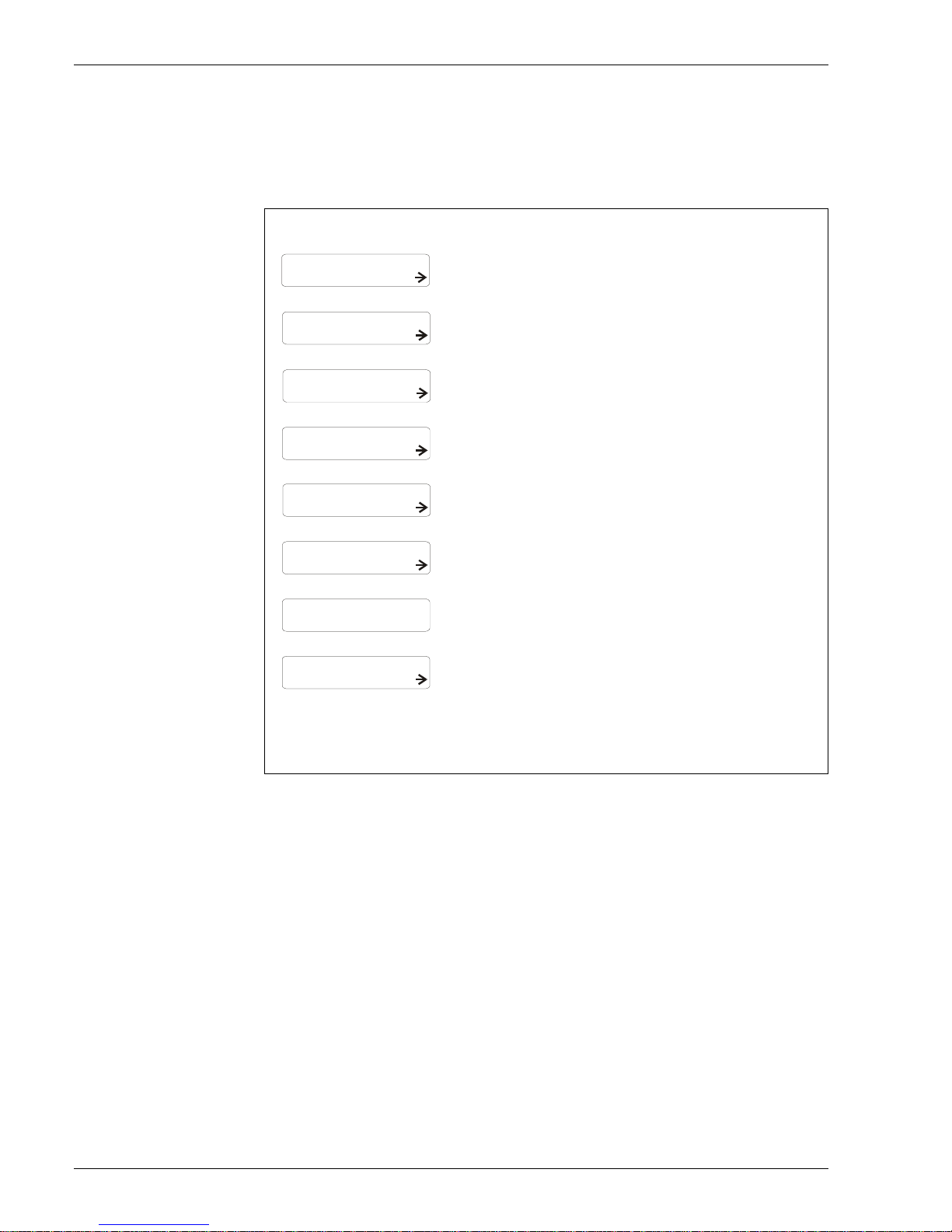
QOG 2: Configuring NMT538 on the matrix
This procedur e mus t be co mp leted; o ther wis e, the Pr os ervo wil l not recognize the connection of
NMT538. The G4 "TEMPERATURE" matrix will be shown only this NMS53x to NMT538
communication is established on the matrix configuration.
SERVICE
OFF
SYSTEM DATA
CALIBRATION
MORE FUNCTION
MORE FUNCTION
MORE FUNCTION
AVERAGE
MA TRIX OF
CONNECTION NMT
MATRIX OF
>GROUP SELECT<: E
>GROUP SELECT<: E
>GROUP SELECT<: E
>GROUP SE LECT<: E
CONNECTION NMT
Enter "E" key several times
until " MO RE FUNCTION" appears
again
Enter " +" key 3 times to display
"SYSTEM DATA", "E" key to confirm
Enter "E" key 3 times to disp l ay
"CONNECTION NMT"
Use "+" or "-" key to selec t temp.
device "AVERAGE"
"E" key once to enter the selection
of Dynamic matrix (G1 to G9)
Enter with "+" key twice, going to
"SERVICE" matrix
Note!
Start at G0 Static Matrix, V4 "MORE
FUNCTION"
Normally, G1: CALIBRATION matrix
to start
Now you are in the
G3 "SERVICE" matrix
Note!
OFF: no temp. device selected
SPOT : connection to 3 wire spot
AVERAGE: connection to NMT
At the "CONNECTION NMT", AVERAGE
must be chosen in order to display
NMT configuration matrix group
G4 "TEMPERATURE"
Move on to the next paramete r
setting at G4 "TEMPERATURE"
matrix
Enter "E" to confirm, then enter "E"
several tim es until "MORE
FUNCTION" appears
LCD display Procedure
Remark
5 Operation with the Proservo NMS53x
Page 27
Prothermo NMT 538
Endress+Hauser Systems & Gauging 27
5.1.6 Setting parameter on the matrix
The connected temp. element data must be input as an initial parameter setting to operate
NMT538 properly.
Note!
The access code 51 will be required for further parameter settings
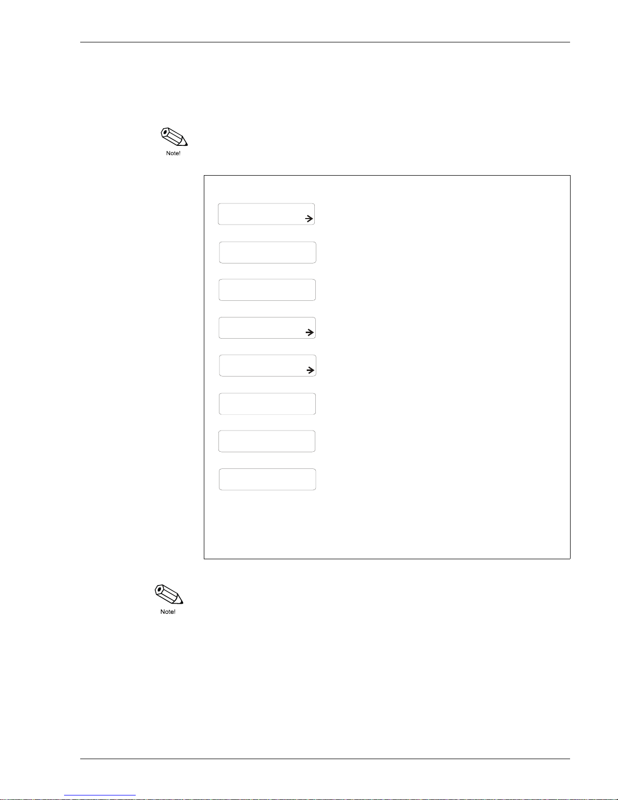
QOG 3 Initial parameter setting of NMT538
Note!
The choice of "EQUAL" or "UNEQUAL" element interval will determine the rest of following
parameter settings.
SERVICE
TOTAL NO ELEMENT
TOTAL NO ELEMENT
KIND OF INTERVAL
16
10
EQUAL
SET DATA NMT
TEMPERATURE
MORE FUNCTION
MORE FUNCTION
MA TRIX OF
MATRIX OF
>GROUP SELECT<: E
>GROUP SELECT<: E
>GROUP SELECT<: E
Enter "E" ke y several times
until "MORE FUNCTION" appears
again
Enter "+ " key 5 times to display
"SET DATA NMT""
Enter "+" key 3 times to displ ay
"TOTAL NO ELEMENT"
Enter desired element number
with "+" or " -" keys (ie,10 in this case)
then, "E" to confirm
Enter "E" key twice, go to
"KIND OF INTERVAL"
Use "+" or "-" key to select
"EQUAL" or "UNEQUAL", then
"E" to confirm.
Enter "E" key several times to exit
"SET DATA NMT" row.
"E" key once to enter the selection
of Dynamic matrix (G1 to G9)
Enter with "+ " or "-" key, goin g to
"TEMPERATURE" matrix
Caution!!
NMT538 must be configured at
the NMS53x matrix GVH 362
"CONNECTION NMT" prior to
perform parameter setting
Now you are in the
G4 "TEMPERATURE" matrix
Note!
Choice of "UNEQUAL" allows specific
element position setting
"EQUAL" automatically establish
each element position by setting
"BOTTOM POINT" &
"ELEMENT INTERVAL"
Default setting would b e 16 (max.
available number)
LCD display Procedure
Remark
5 Operation with the Proservo NMS53x
Page 28
Prothermo NMT 538
28 Endress+Hauser Systems & Gauging
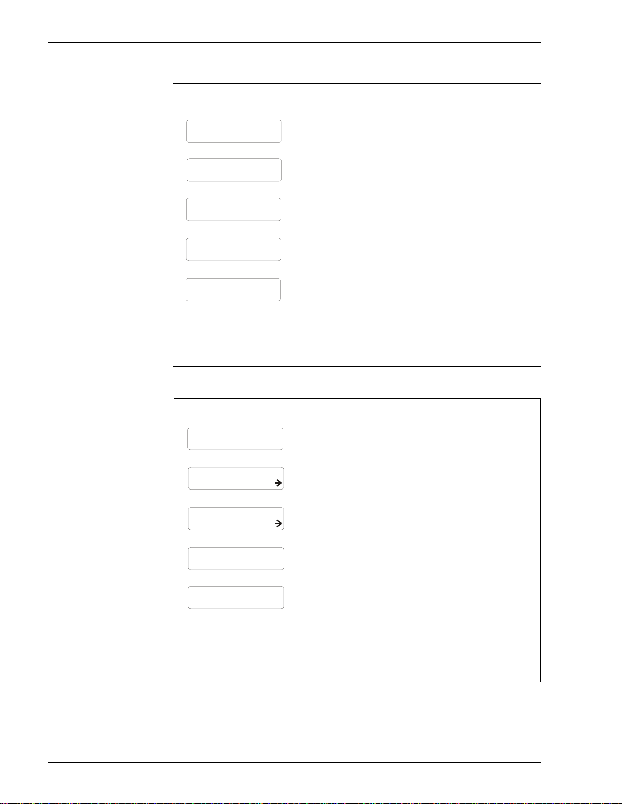
QOG 4 Equal element interval setting
QOG 5 Unequal element interval setting up to 10 elements
500mm
KIND OF INTERVAL
EQUAL
750mm
2000mm
1200mm
BOTTOM POINT
BOTTOM POINT
ELEMENT INTERVAL
ELEMENT INTERVAL
"E" to confirm, and enter "E" again
to switch matrix to
"ELEMENT INTERVAL"
Enter "E" key to confirm, go to
additional parameter setting
if necessary
After confirming "EQUAL" element
interval, enter "E" key once,
go to "BOTTOM POINT"
Enter with "+" or "-" key to set desired
lowest element position
Enter with "+" or "-" key to set desired
"ELEMENT INTERVAL"
Note!
Default setting of "BOTTOM POINT" is
500mm,
The element connected to NMT538
input brown wire (#1) will be controlled
by this "BOTTOM POINT" setting.
Note!
Default setting of "ELEMENT INTERVAL"
is 2000mm
This element interval data applies to
all the elements to be equally spaced
LCD display
Procedure
Remark
UNEQUAL
ELEM. 1 POSITION
ELEM. 1 POSITION
500mm
655mm
SET DATA NMT
ELEMENT POSITION
KIND OF INTERVAL
>GROUP SELECT<: E
>GROUP SELECT<: E
Enter "E" key once, go to " ELEM. 1
POSITION"
"E" to confirm, then enter "E" to go to
"ELEM. 2 POSITION. Repeat same
procedure until the last element.
"E" key once to confirm
"UNEQUAL INTERVAL" then,
enter "E" several times, return to
"SET DATA NMT"
Enter with "+" or "- " key, going to
"ELEMENT POSITION"
Using "+" or "-" key to enter the lowest
element position
Note!
Up to 10 element positions can be set
at 10 matrix of "ELEME NT POSITION"
More than 11 elements are existed, go
to "NMT ADJUSTMENT"
Choice of "UNEQUAL" allows specific
element position setting
LCD display Procedure
Remark
5 Operation with the Proservo NMS53x
Page 29
Prothermo NMT 538
Endress+Hauser Systems & Gauging 29
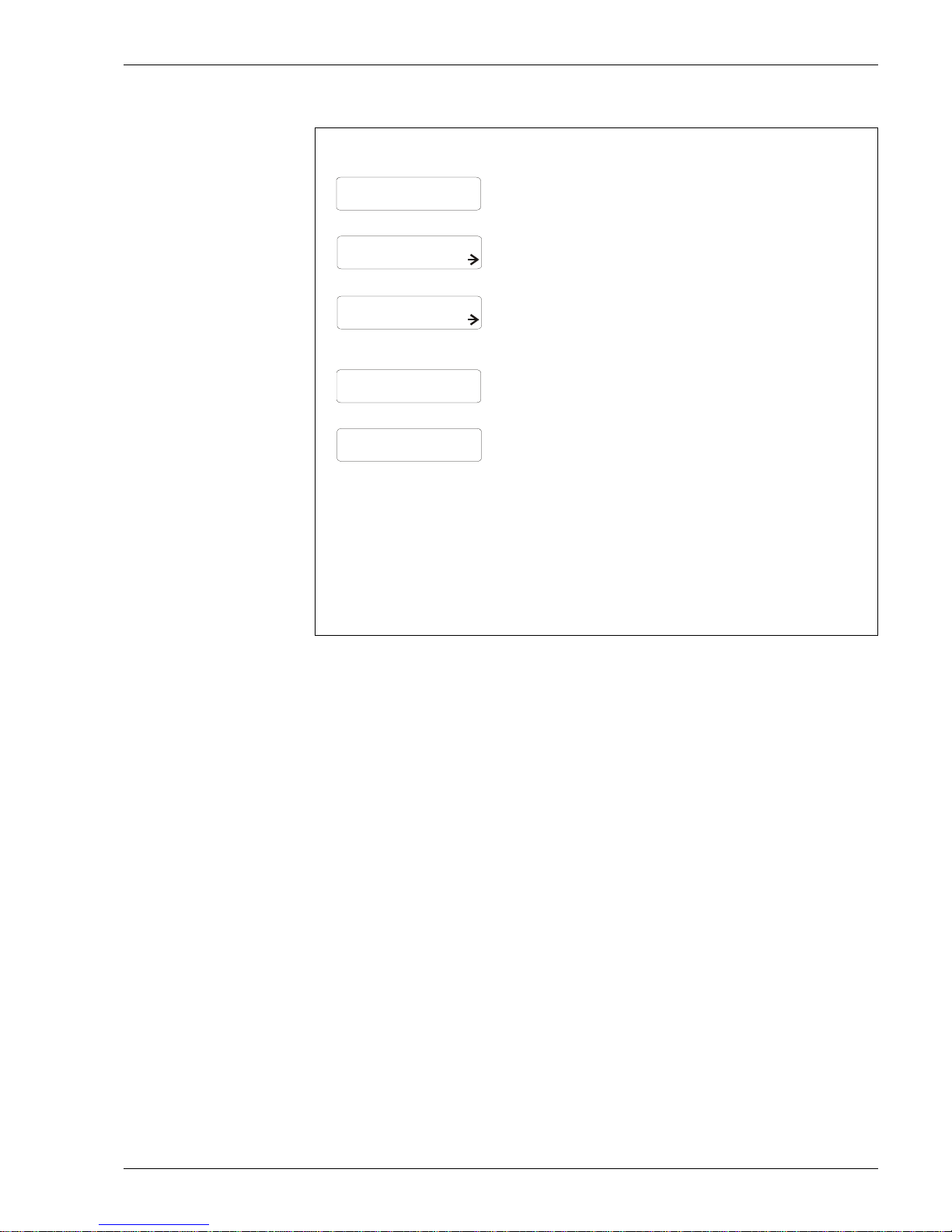
QOG 6: Unequal element interval setting more than 11 elements installed
UNEQUAL
SELECT POINT
ELEMENT POSITION
0
655mm
SET DATA NMT
NMT ADJUSTMENT
KIND OF INTERVAL
>GROUP SELECT<: E
>GROUP SELECT<: E
Enter "E" key once, go to
"SELECT POINT" then, select set
number from 0 to 15 by "+" or "-"
key, and "E" to confirm
Set desired element position by
"+" or "-" key, then "E" to confirm.
Enter "E" several times until next
"SELECT POINT" appears, then set
next element position.
Repeat same procedure until the
last element position is set.
"E" key once to confirm
"UNEQUAL INTERVAL" then,
enter "E" several times, return to
"SET DATA NMT"
Enter with "+" or "-" key, going to
"NMT ADJUSTME NT" matrix
Enter "E" 4 times, go to "ELEMENT
POSITION"
Note!
Up to 10 element positions can be set
at 10 matrix of "ELEMENT POSITION"
row."
Caution!!
#1 element is set at "SELECT POINT 0"
; therefore, #16 element will be set at
"SELECT POINT 15".
Choice of "UNEQUAL" allows specific
element position setting
LCD display Procedure
Remark
5 Operation with the Proservo NMS53x
Page 30

Prothermo NMT 538
30 Endress+Hauser Systems & Gauging
5.1.7 Additional parameter setting functions
Refer to each matrix position in G4 "TEMPERATURE" & G7 "ADJ SENSOR" matrix
ZERO ADJUSTMENT GVH471: default setting 0
The base line adjustment when the measured value need to be adjusted. i.e. Entering desired
value; for example, “2” when the NMT 538 indicates 23
°C in compare to the reference
thermometer value indicates 25
°C.
AVERAGING GVH478: default setting 2
Sampling number of average calculation. Can be increased up to 16 times depending on
instability of data acquisition by noise factor and others.
PREAMBLE NUMBER GVH483: default setting 5
Based on the HART protocol definition, selectab le up to 16 preamble num bers, depending on the
condition of local HART communication.
TEMP. ELEM. SHORT GVH488: default value -49.5°C (-57.1°F)
Error display with a temp. v alue when an eleme nt or c irc uit is short. Set the des ir ed val ue w ith "+"
or "-" key, then "E" to confirm.
TEMP. ELEM. OPEN GVH489: default value 359°C(679.1°F)
Error display wit h a te mp. v alue w hen an el ement or cir cu it is open. Set the desi red valu e wi th "+"
or "-" key, then "E" to confirm
OUTPUT AT ERROR GVH492: default value ON
"ON" to display short or open circuit value (-49.5 or 359) on HOME position and both average
temp. data (liquid & gas phase). Disable average calculation due to defected element or circuit
exist. "OFF" to enable average calculation with last available data. The matrix of individual
defected element number indicates short or open circuit information regardless.
CUSTODY TRANSFER GVH493: default setting OFF
A function to freeze set parameter of NMT538 once it is turned on. Needs to turn off when initial
parameter is required to over write
POLLING ADDRESS GVH494: default setting 2
Select other addr ess with "+ " or "-" key i n case of c onnecting to any other HAR T device and requir e
changing the address.
5 Operation with the Proservo NMS53x
Page 31

Prothermo NMT 538
Endress+Hauser Systems & Gauging 31
5.2 The Proservo NMS53x matrix (NMT538 related matrix
only)
Matrix G0 Static matrix
5 Operation with the Proservo NMS53x
NMS53x Programming Matrix (Static Matrix)
GROUP MESSAGE 0 1 2 3 4 5 6 7 8 9
16000.00 mm 0.0 mm 0.0 mm 0.0 mm 0.0 m m 1.000 g/ml 1.000 g/m l 1.000 g/ml 0.0 mm OFF
MEASURED VALUE 1
0
MEASUREDLEVEL ULLAGELEVEL UPPER INTERF. LEVMIDD. INTERF. LEV BOTTOM LEVEL UPPER DENSITY MIDDLE DENSITY DENSITY BOTTOM LEVEL DATA STATUS1
Display Display Display Display Display
0.000 - 3.000
Display/Set(50)
0.000 - 3.000
Display/Set (50)
0.000 - 3.000
Display/Set (50) Display
ON
Display
0.0
o
c0.0
o
c
0 mm 16000.0 mm mm
MEASURED VALUE 2
1
LIQUID TEMP. DEV(1) DEV(2) GAS TEMPERATURE ZERO POINT SPAN LENGTH UNIT
Display Display Display Display Display Display Display
STOP STOP UNBALANCED LEVEL LEVEL 411 8424
OPERATION
2
OPERATION 16000 OPERATING STAT U S BALANCING STATUS OPERAT.BY NR F OPERAT.BY HOST DEVICE ID SOFTWARE VE RSION
See below operation
commands
Select (50)
See below status table
Display Display Display Display
CALIBRATION 98 627 8:21:00 NO ALARM NO ALARM NO ERROR MPU:START ACT 0
MORE FUNCTION
3
MATRIXOF CALENDER ALARMCONTACT0LA0000 DIAGNOSTICCO09862775200 ACCESSCODE
Select
Currect data
Display
Currect data
Display
Currect data
Display
Currect data
Display
Currect data
Display
0 , 50, 51, 777
Set
V
H
Page 32

Prothermo NMT 538
32 Endress+Hauser Systems & Gauging
Matrix G3 Service matrix
NMS 53x Program m ing Matrix (Dynamic M atrix, Service: G3)
GROUPMESSAGE0123456789
300.00 m m 1.4 g / 10m 255.0 g 145.0 mL 60 mL 1.0 m L 20 X 100 m S 0.00 mm /m 0 c ount
MEAS.WIRE & DRUM
4
WIRE DRUM CIRC. WIRE WEIGHT DISPLACER W EIGHTDISPLACER VOLUMEBALANCE VOLUME VOLUME TOLERANCE DELAY DRUM CORRECTIONDISPL.HUNT.COUNT
0 - 999.9
Set (51)
0 - 999.9
Set (51)
0 - 999.9
Set (51)
0 - 999.9
Set (51)
0 - 999.9
Set (51)
0-99.9
Set (51)
0-99
Set (51)
0-99.00
Set (51)
0-99
Set (51)
OFF OFF 0 s 50 m m Current D ata
GAUGE DATA 5 NO N HYSTER. MODEHI. ACCURACY MODEHI.ACCR. OPE. TIMEHI. ACC. DISP. UP GAUGE TEMP.
ON
Select (51)ONSelect (51)
0-600
Set (51)
0-300
Set (51) Display (51)
LOCAL : MASTER OFF OFF OFF
SYSTEM DATA
6
SENSOR DATA
CONNECTIONNRF CONNECTION NMT SOFT RESET
REMOTED COM . ON
SOFTWAR E = 04.20
HARDWARE=TC B04
GEAR 1:36
NOT OVERSPILL
CONTACT 1
CONTACT 2
Select (51)
SPOT TEMP.
AVERAGE TEMP.
Select (51)
ON
Select (51)
0.0 g OFF OFF OFF 70 m m 0.0 g
SERVICE
7
MEASURED W EIGHTRELE. OVER TENS DRUM SETTING WEIGHT CALIBR.
DISPL.REFERENCE ZERO ADJ.W EIGHT
Display
ON
Select (51)ONSelect (51)ONSelect (51) Set (51) Set (51)
Sa=21000:A=21000
SENSOR VALUE
8
Sb=11000:B=11000
Display (51)
0 0 0.0g 0 0 0..0g
SENSOR DATA 9 WT.COUNT CAL A WT.COUNT CAL B
Display (51) Display (51)
V
H
5 Operation with the Proservo NMS53x
Page 33

Prothermo NMT 538
Endress+Hauser Systems & Gauging 33
Matrix G4 Temperature matrix
NMS53x Programming Matrix (Dynamic Matrix, Temperature: G4 )
GROUP MESSAGE 0 1 2 3 4 5 6 7 8 9
xxoCzz
o
C
aaaa.a mm VH00
0.0oC150.0
o
C
TEMPERATURE DATA
4
LIQUD TEMP.
GAS TEMPERATURE
MEASURED LEVEL LEV.DATASELECT REFERENCE ZERO REFERENCE 150
Current data
Display (51)
Current data
Display ( 51)
Current data
Display (51)
VH08
Select (51)
Current d ata
Display ( 51)
Current dat a
Display (51)
aa.a
o
Cbb.b
o
C cc.coC dd.doCee.e
o
Cff.f
o
Cgg.g
o
Chh.h
o
C hh.hoCjj.j
o
C
ELEMENT TEMP. 5 TEMP. NO.1 TEMP. NO.2 TEMP.NO.3 TEMP. NO.4 TEMP. NO.5 TEMP. NO.6 TEMP. NO.7 TEMP. NO.8 TEMP. NO.9 TEMP. NO.10
Current data
Display (51)
Current data
Display ( 51)
Current data
Display (51)
Current data
Display (51)
Current data
Display ( 51)
Current data
Display (51)
Current data
Display (51)
Current d ata
Display ( 51)
Current data
Display (51)
Current dat a
Display (51)
xxx.x mm xxx.x m m xxx.x mm xxx.x mm xxx.x mm xxx.x mm xxx.x mm xxx.x mm xxx.x mm xxx.x mm
ELEMENT POSITION
6
ELEM.1POSITION ELEM.2 POSITION ELEM.3POSITION ELEM.4POSITION ELEM.5 POSITION ELEM.6POSITION ELEM.7POSITION ELEM.8 POSITION ELEM.9 POSITION ELEM.10 POSITION
Current data
Display (51)
Current data
Display ( 51)
Current data
Display (51)
Current data
Display (51)
Current data
Display ( 51)
Current data
Display (51)
Current data
Display (51)
Current d ata
Display ( 51)
Current data
Display (51)
Current dat a
Display (51)
0
x.x
o
Cxx.x
o
C
xxx.x mm 2
NMT ADJUSTMENT
7
SELECT POINT ZERO ADJUST ELEMENT TEMP
ELEMENT POSITION
AVERAGE TIME
0-15Selectable
SELECT POINT + 1
= ELEMENT No.
Set(51) Set(51)
Current data
Display (51)
Current data
Display ( 51) Set (51)
0 16 5 EQUAL 500.0 mm 2000.0 mm
-49.5
o
C359.0
o
C
SET DATA NMT
8
DIAGNOSTIC TOTAL NO.ELEMENTPREAMBLE NUMBER
KIND OF INTERVAL
BOTTOM POINT
ELEMENT INTERVAL TEMP.ELEM.SHORT TEMP.ELEM. OPEN
Display (51)
2-16
Set (51)
1-16
Set (51)
UNEQUAL
Select (51)
0.0 m m to 500.0 mm
valuable
Set (51) Set (51) Display (51) Display (51)
xxxxxx OFF 2 17 6 2 183
DEVICE DATA NMT
9
INSTRUMENTCODE LAST DIAGNOSTIC OUTPUT AT ERROR CUSTODY TRANSFER POLLING ADDRESS MANUFACTURE ID SOFTWARE VERSION HARDWARE VERSION DEVICE TYPE CODE
Display (51) Display (51) Select (51)
ON
Display (51) Display (51) Display (51) Display (51) Display (51)
181
Display (51)
V
H
5 Operation with the Proservo NMS53x
Page 34

Prothermo NMT 538
34 Endress+Hauser Systems & Gauging
Matrix G7 Adjust Sensor matrix
5 Operation with the Proservo NMS53x
NMS53x Program ming M atrix (Dynamic Matrix, ADJ. SENSO R: G7)
GROUPMESSAGE0123456789
ADJ. SENSOR 4 ADJ. A ZERO ADJ. A SPAN ADJ. B ZERO ADJ. B SPAN
0.00% 0.00% 0.00% 0.00%
HART ERROR RATE 5
ERR. RATE NM F ER.RATE NMT ERR. RATE DEV(1) ERR. RATE DEV (2)
UNIT 6
TERMINAL PORT B TERMINAL PORT B TERMINALP ORT B
HART LINE 7 NMT HART DEVICE (1) HART DEVICE (2)
TERMINAL POR T A
Select (777)
TERMINAL PORT A
Select (777)
TERMINAL PORT A
Select (777)
0.3 mL 150 15 0.0 mm 0.0 mm
INTERFACE ADJUST 8 VO L.TOL.FOR I/F BRAKE R ATE BALANCE COUNT IF1 OFFS ET IF2 OFFSET
0-99.9mL
Set (51)
0-255
Set (51)
0-255
Set (51)
0 - 9999.9 mm
Set (51)
0 - 9999.9 mm
Set (51)
NONE 9
V
H
Page 35

Prothermo NMT 538
Endress+Hauser Systems & Gauging 35
5.3 Description of the programming matrix
The description of followin g matrix design & cont ents are based on accessibility fr om the Proserv o
NMS53x. Further detailed operation is required, please refer to the operation manual of the
Proservo NMS53x.
Matrix group Function group Item Access
code
Short description Default vaule Set
Select
Display
Possible settings,
selections, or displays
IndexNo,
GVH
STATIC MATRIX
(This word is not
shown)
MEASURE DVALUE2
LIQUID TEMP. 0
If a temperature bulb is connected, then this position shows
the measured liquid temperature. Otherwise the LCD will be
blank.
0.0 °C Display -49.9 ... 249.9 °C 010
GAS TEMPERATURE 0
If a temperature bulb is connected, then this position shows
the measured gas temperature.
0.o °C Display -49.9 ... 249.9 °C 013
MORE FUNCTION
MATRIXOF 0 Selection of the dynamic matrix of the programming matrix CALIBRATION Select
CALIBRATION
DEVICEDATA
SERVICE
TEMPERATURE
HART DEVICE (1)
HART DEVICE (2)
ADJ. SENSOR
030
(Calendar) 0
Calendar and clock without daylight saving system.
NOT TRANSFERRED BY RACKBUS.
Japanese
local time
Display
e.g. 1 410 19:10:41
Year Month Day
HH:MM:SS
033
DIAGNOST ICCO 0 Self diagnosis at the moment Display
Errormessage (refer to
attached table)
036
(ErroneousMessage) 0
Previous alarm with message.
Only the last alarm code is transmitted by Rackbus.
(Erroneous
Date)
Display
Errormessage
(refer to attached table)
037
ACCESSCODE 0 Access code for programming (see Sec. 10.4) 0 Set 0... 9999 039
SERVICE SYSTEM DATA
CONNECTION NMT 51 Connection of the Prothermo NMT538 OFF Select
OFF
SPOT(three wire RTD
input)
Average (NMT538)
362
5 Operation with the Proservo NMS53x
Page 36

Prothermo NMT 538
36 Endress+Hauser Systems & Gauging
Ma trix group Function group Item Access
code
Short description Default vaule Set
Select
Display
Possible settings,
selections, or displays
Index N o,
GVH
TEMPERATURE
TEMPERATURE DATA
LIQUID TEMP. 51 Current average liquid temperature. Display -49.9 ... 249.9 °C 440
GAS TEMPERATURE 51 Current averag e gas temp erature. Display -49.9 ... 249.9 °C 441
MEASURED L EVEL 51
Level from the Proservo. The level data are used for the
averaging of liq uid and g as temperatures.
Display 0.0 ... 99999 mm 442
LEV.DATA SELECT 51
Possible to select a measured level data from matrix pos.
GVH=000 (d isp lacer p osition), or GVH=008 (leveld ata after
balanced).
VH00 Select
VH00
VH08
443
REFERENCE ZERO 51
Display of reference resistance on printed circuit board that
correspond s to 0 °C.
0.0 °C Display 447
REFERENCE JPT150 51
Display of reference resistance on printed circuit board that
correspond s to JPT150 °C.
152.5 °C Display 448
REFERENCE 1 50 51
Display of reference resistance on printed circuit board that
correspond s to 150 °C.
150.0 °C Display 449
ELEMENT TEMP.
TEMPNO. 1 51 Temperature of element No. 1 (d eep est point) Display -49.9 ... 249.9 °C 450
TEMPNO. 2 51 Temperature of element No. 2 Display -49.9 ... 249.9 °C 451
TEMPNO. 3 51 Temperature of element No. 3 Display -49.9 ... 249.9 °C 452
TEMPNO. 4 51 Temperature of element No. 4 Display -49.9 ... 249.9 °C 453
TEMPNO. 5 51 Temperature of element No. 5 Display -49.9 ... 249.9 °C 454
TEMPNO. 6 51 Temperature of element No. 6 Display -49.9 ... 249.9 °C 455
TEMPNO. 7 51 Temperature of element No. 7 Display -49.9 ... 249.9 °C 456
TEMPNO. 8 51 Temperature of element No. 8 Display -49.9 ... 249.9 °C 457
TEMPNO. 9 51 Temperature of element No. 9 Display -49.9 ... 249.9 °C 458
TEMPNO. 10 51 Temperature of element No. 10 Display -49.9 ... 249.9 °C 459
Note!
The whole
matrix is
available when
NMT is
connected and
SPOT or
AVERAGE
temperature
element is
selected.
Note!
For elements with
numbers b eyond
the value set a t
GVH=482, the LCD
will show 358.0 °C
5 Operation with the Proservo NMS53x
Page 37

Prothermo NMT 538
Endress+Hauser Systems & Gauging 37
Matrix group Function group Item Access
code
Short description Default vaule Set
Select
Display
Possib le settings,
selections, or displays
Index N o,
GVH
TEMPERATURE ELEMENT POSITION
ELEM. 1 POSITION 51
Position of temperature element No. 1 (deepes t point),
namely Bottom Element.
500mm Display 0 ... 9999 9 mm 460
ELEM. 2 POSITON 51 Position of tem perature element N o.2 2500mm Display 0 ... 9999 9 mm 461
ELEM. 3 POSITON 51 Position of tem perature element N o.3 4500mm Display 0 ... 9999 9 mm 462
ELEM. 4 POSITON 51 Position of tem perature element N o.4 6500mm Display 0 ... 9999 9 mm 463
ELEM. 5 POSITON 51 Position of tem perature element N o.5 8500mm Display 0 ... 9999 9 mm 464
ELEM. 6 POSITON 51 Position of tem perature element N o.6 10500mm Display 0 ... 99999 mm 465
ELEM. 7 POSITON 51 Position of tem perature element N o.7 12500mm Display 0 ... 99999 mm 466
ELEM. 8 POSITON 51 Position of tem perature element N o.8 14500mm Display 0 ... 99999 mm 467
ELEM. 9 POSITON 51 Position of tem perature element N o.9 16500mm Display 0 ... 99999 mm 468
ELEM. 10 POSITION 51 Position of temperature e leme nt N o.10 18500mm Display 0 ... 99999 mm 469
NMT ADJUSTMENT
SELECT POINT 51
Element numb er selection for reading elem ent temperature
and position from ele ment No. 11 to N o . 16.
0Display
0 (elementNo.1)
10 (elementNo.11)
470
ZERO A DJU STMENT 51 Zero adjustment Set -20.0 ... 20.0 °C 471
ELEMENTTEMP. 51 Element temperature selected at "SELECT POINT" Display -49.9 ... 249.9 °C 473
ELEMENTPOSITION 51 Element position selected at "SELECT POINT" Display 0 ... 99999 mm 474
AVERAGING 51
Sampling coefficient for averaging of data. If there is a high
degree of instability d ue to noise or other factors, increase ist
value.
2 Set 1 ... 10 478
Note!
The LCD shows
the element
position meas ured
from the tank
bottom (for
previously set
elements only).
Note!
The whole
matrix is
available w hen
NMT is
connec te d and
SPOT or
AVERAGE
temperature
element is
selected.
5 Operation with the Proservo NMS53x
Page 38

Prothermo NMT 538
38 Endress+Hauser Systems & Gauging
Matrix group Function group Item Access
code
Short description Defaultvaule Set
Select
Display
Possible settings,
selections, or displays
IndexNo,
GVH
TEMPERATURE NMT SETDATA
DIAGNOST ICCODE 51 Display of current diagnostic code. 0 Display 0 ... 255 480
TOTAL NO. ELEMENT 51
Thetotal number of elements that are mounted in the flexible
tube. This number is determined in accordance with the
specifications provided when the order of the device is
placed.
16 Set a ... A HEX 482
PREAMBLE NUMBER 51
Display of preambles for HART
®
protocol.
5 Display 2 ... 14 HEX 483
KIND OF INTERVAL 51
Temperature element intervals.
- Equal intervals: 0
- Unequal intervals: 1
If 1 is chosen, then set the element position on matrix from
GVH=460toGVH=469.
0 Set 0or 1 485
BOTTOMPOINT 51
Height of bottom point.
Only available when equal intervals are selected.
500mm Set 0.0 ... 99999.9 mm 486
ELEMENT INTERVAL 51
Interval between temperature elements.
Only available when equal intervals are selected.
2000mm Set 0.0 99999.9 mm 487
TEM. AT SHORT ELE. 51
Temperature indication when element is shorted. This value is
sent to the Proservo only when the error output is "ON" at
GVH=492. When the error output is "OF F", the average
temperature is sent to the Proservo.
-49.5 °C Set 488
TEM. AT OPEN ELE. 51
Temperature indication when element is opened. This value is
sent to the Proservo only when the error output is "ON" at
GVH=492. When the error output is "OF F", the average
temperature is sent to the Proservo.
359.0 °C Set 489
Note!
Thewhole
matrix is
available when
NMT is
connected and
SPOT or
AVERAGE
temperature
element is
selected.
5 Operation with the Proservo NMS53x
Page 39

Prothermo NMT 538
Endress+Hauser Systems & Gauging 39
Matrix group Function group Item Access
code
Shortdescription Default vaule Set
Select
Display
Possible settings,
selectio n s,ordisplays
Index No,
GVH
TEMPE RATURE NMT DEVICE DATA
INSTR UM EN TCODE 51 Display of the hardware unit number Display 490
LAST DIAGNOSTIC 51
Display of the last error message. If there was no error, then
theLC Dwill be blank.
Display 491
OUTPUT AT ERROR 51
Selection of output and indication in case of short circuit or
open circuit elements at GVH=488 or 498
1Sdelect
0: OFF
1: ON
492
CUSODY TRANSFER 51
Custody transfer mode. If this mode is switched on, then the
LCDwill show on.
OFF Sdelect
OFF
ON
493
POLLINGADDRE S S 51
Assignment of an address to Prothermo NMT538when this
and other HART
®
device saremulti-dr opped ontheHA RT
®
com munication line.Polling addres s2 isfixedby Proservo
firmware.
2Set
1...F
(Total 16 address can be
set.)
494
MANUFACTURERID 51
Identification number of the manufacturer (17 for
Endress+Hauser).
17 Display 495
SOF TW A REVERS ION 51 Software version of the ProthermoNMT538. 5.0 Display 4.0 or higher 496
HARD W AREVERS ION 51 Hardware version of the Prothermo NMT538. 1.4 Display 1.4 or higher 497
DEVICE TYPECODE 51
Display of the device type code (181 for the Prothermo
NMT538)
181 Display 499
ADJ. SENSOR HART LINE
NMT 777
Assignment of Prothermo NMT538with ISHARTor Non-IS
HARTconnection.
- TER MINALPOR TB: Non-IS HARTconnection
- TER MINALPOR TA: IS HARTconnection
TERMINAL
PORT B
Set
TERMINAL PORT B
TERMINAL PORT A
770
Note!
Thewhole
matrix is
available when
NMTis
connected and
SPOT or
AVERAGE
temperature
element is
selected.
5 Operation with the Proservo NMS53x
Page 40

Prothermo NMT 538
40 Endress+Hauser Systems & Gauging
6 Operation with the Tank Side Monitor NRF590
The wiring between the P rothermo NMT 538 to NRF 590, re fer to the sec tion 3.4 H ART line cabling
prior to the actual operation throug h NRF5 90.
6.1 Initial NMT538 configuration before connect to NRF590
Caution!
Nature of the Prothermo NMT538 indicates various acceptability of foreign RTD average probe
connection for converting the E+H standard HART communication device.
Following terms must be clarified and preliminary configured by auxiliary HART communication
device; for example, ge neric HAR T communica tor , service t ool like ToF (Time of Flight ) tool, or the
Proservo NMS.
-Number of element: NMT538 is normally delivered with 16 element numbers (maximum
connection). If fewer element numbers will be connected without proper set up, the average
temperature data will be unavailable due to the presence of element with no response. (Display
of error message 358.5°C)
-Lowest element position: The default lowest element position of NMT538 is 500mm (19.7").
-Element interval: Based on the configuration of connected average temperature probe, each
element position must be determined by interval between elements. Default setting is 2000mm
(78.7") equally spaced interval.
6.2 Additional adjustment factors
The Prothermo NMT5 38 has it s own pr ogrammin g matrix th at only E+ H Sakura factory device can
access to. Following terms should be consulted with E+H personnel at ordering of the NMT538.
-Liquid offset level: In order to calculate liquid average temperature, only elements submerged
below 300mm (11.8") f rom the measured liquid level are involved in calculation. This o f fs et va lue
can be entered only at the factory set up.
-Gas offset level: Just like liquid offset level, the gas phase average temperature calculation
includes the element that locates at least 300mm above measured liquid surface. The default
setting (300mm) can be only altered at the factory faci li ty.
Note!
All of above initial configuration can be executed from ToF (Time of Flight) service tool with
NMT538 Device Description implemented.
6.3 NMT 538 operation from NRF 590 Tank Side Monitor
The NRF 590 Tank Side Monitor alre ady has pr e installe d device m enu for the NMT 538 a s well a s
FMR series radar level gauge. As soon as necessary hardware installation (includes device
setting & wiring) is co mpleted, t he NMT 538 is activ ated by th e NRF 590’s power supply on the IS
HART loop. The dev ice co nfiguration from th e NR F 590 to the N MT 538 is limited to the fo llo wing
items.
• Preamble Cmd (07c46)
• Tag (07c48)
• Temperature units (07c56)
• Level units (07c75)
• Address (07w42)
Note!
As long as necessary initial configurations are completed, NMT 538 shall be able to start
measuring temperature inside the tank as well as calculating both liquid & gas average
temperature based on liquid level acquired from the FMR series radar level gauge.
Please refer to the NRF 590 Tank Side Monitor operation manual for the data displaying
functionality.
6 Operation with the Tank Side Monitor NRF 590
Page 41

Prothermo NMT 538
Endress+Hauser Systems & Gauging 41
7 Configuration from ToF (Time of Flight) tool
In order to acc ess NMT 538 p arameters dir ectly throu gh T o F (Time of Fight) t ool, least belo w listed
items are required.
1. NMT 538 DD (Device Description) for ToF tool.
2. E+H HART modem with 232C connector
3. ToF installed computer (Do not us e c onv en tional Lap Top computer at hazard ous are. Be sure
to use intrinsically safe computer if on site configuration is required.)
7.1 NMT 538 DD installation in T oF tool environment
1. Within the NMT 5 38 DD CD package, copy entire "NMT538_ V010200_HART" folder into ToF T ool
; Dev DB folder.
2. Open "NMT538_V010200_HART" folder and select "enu".
3. Within "enu" folder, Right click on "NMT538_dd.enu.dll", and click on "Resister COM Server".
4. Installation of NMT 538 DD will automatically start, then click "Yes" to finish installation.
7.2 NMT 538 Configuration on ToF tool
Note!
Hook up the E+H HART mode m in the NMT 538 co nnected HART lo op prior to ToF tool activation
on your computer.
In case the host gauge to be the NRF 590 Tank Side Monitor, set "HART SCANNER" menu to
"DISABLE" on NRF 590. Due to the cha racteristic of multi drop HART loop, pr esence o f two HAR T
master devices may cause configuration problem.
7.2.1 ToF tool activation
Start up the ToF tool and select "SCAN-BUS" to seek available HART device on the loop. Since
NMT 538 has no own operation al power supply, it has to be connected NMS 53x Pr oservo or NRF
590 Tank Side Monitor to provide proper operation DC voltage.
Once the NMT 538 is re cognized on the H ART loop, device list on the bottom of the screen sho uld
indicate the presence of NMT 538. Then double click on the NMT 538.
7.2.2 NMT 538 DD structure
NMT 538 DD is structured in 4 separate groups.
Temperature: data display only
All of parameters are display only. Reading of various temperature related data form the NMT 538.
NMT Set Data: data display & parameter configuration
Most of these parameters are named and positioned based on the Proservo NMS"s matrix
numbers. Please refer to the section 5.6.1 "Setting Parameter on the Matrix and section 5.6.1
"Additional Parameter Setting".
NMT Device Data: device data display
Most of parameters ar e display of NMT’s own dev ice inf ormation except "tag no." and "as se mb ly
number". These two are the only parameters you can configure in this group.
Position: data display & parameter configuration
Display of element positio n from elem ent 1 to 10. If "Even Interva l" is chosen and "Bottom Element
Position" is configu r e d in NM T Se t Da ta g roup, no parameter set would be necessary. If "Uneven
Interval" is chosen, this is the group to set element position (only element 1 to 10).
Note!
You have to go back to NMT Set Data and select "Calibration Select" to choose element number
and "Position X" to enter element position for element 11 to 16 (1 to 10 can be configured same
way in this method).
7.3 NMT 538 default value
NMT 538 is configure d in mo st co mm on param ete rs at fac tory set up. Normall y yo u do no t hav e
to set all of parameters. Please refer to the ToF tool instruction within the screen. Common
parameters are,
Bottom Element Position: 500mm
Element Interval: equal
Number of Element: 16 elements
Please refer to the section 5.1.7 "Additional Parameter Setting" to confirm rest of default value.
7 Configuration from ToF tool
Page 42

Prothermo NMT 538
42 Endress+Hauser Systems & Gauging
8 Error code
NMT538 has functionality of self diagnostic error detection for both electrical & mechanical
conditions. NMT538 also transmits those conditions to various error displays and message to
inform connected host gauge.
Note!
Most of error message remains even after correcting or fixing problems. Reset the software to
default setting (device configuration data will be remained) or turning the power supply once is
necessary
Error display
NMT538 has several numeric error status indication.
-49,5°C (-57.1°F): Element short
Element or wiring circ uit o n particul ar el em ent num ber i s el ect rica lly or ph ys ica ll y sh ort. Can be
shown either individual and / or average temp. matrix depending on error display set up.
358°C (676.4°F): Unsuitable element position
358°C will be shown on the l iquid avera ge temp. dis play when the liquid le vel is bel ow the lowes t
element position. On the other hand, 358°C is also shown on gas / vapor average temp. display
when all elements are completely submerged in the liquid.
358.5°C (677.3°F): Invalid element data reading
A display when operator seeks for non-existing element data. i.e. #12 element data on only 10
elements are connected. This is different from 359°C Element open. The entered value of
configured element number must meet the actual number of connected elements.
359°C (678.2°F): Element open
Element or wiring circuit on particular element number is electrically or physically open. Can be
shown either individual and / or average temp.
359.5 °C (679.1°F): Communication error
HART Communic ation err or, caused by device to de vice local HAR T co nnecti on. Only N MS uses
this error display mainly for remote communication data transmission.
Chart 6: Error message
Message Cause Remedy
TEMP.COM.OPEN Common line for elements
break.
Check the common line for
elements. Consult E+H
Service for replacement of
the temperature sensor.
TEMP.COM.SHORT Common line for elements
short circuit.
Check the common line for
elements. Consult E+H
Service for replacement of
the temperature sensor.
ELEM.X OPEN
X = 1...16
No. x element (or line) break. Check the element. Measure
the resistance by attaching a
Digital Multimeter rod to the
connector. (*)
ELEM. XSHORT
X = 1...16
No. X element (or line) short
circuit.
Check the element. Measure
the resistance by attaching a
Digital Multimeter rod to the
connector. (*)
(*) Never use an analog-type tester, which would allow too much electric current to
flow to the measuring element when determining the resistance. The current
should be limited to 1 mA or less during such a test.
8 Error code
Page 43

Prothermo NMT 538
Endress+Hauser Systems & Gauging 43
Message
Cause
Remedy
ELEM 0 RANGE OVER
The reading of the reference
resisrance (0 C) on the
printed circuit board is out of
tolerance.
The circuit board should be
replaced. Contact E+H
service.
TEM BELOW RANGE
The measured temperature
is below the set range.
Measure the temperature in
the tank. If it is significantly
different from the indicated
Prothermo setting, check the
temperature-element
resistance.
TEM OVER RANGET
The measured temperature
is above the set range.
Measure the temperature in
the tank. If it is significantly
different from the indicated
Prothermo setting, check the
temperature-element
resistance.
BELOWBOT. POINT
The level data are below the
lowest (bottom) element.
The reading gives only the
average gas temperature.
8 Error code
Page 44
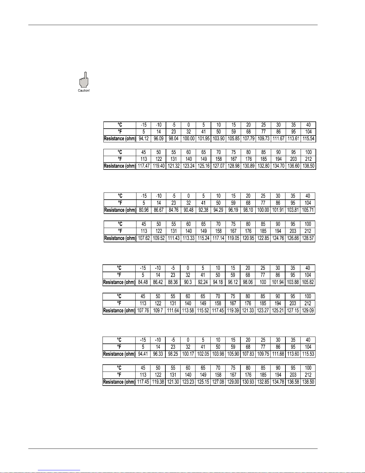
Prothermo NMT 538
44 Endress+Hauser Systems & Gauging
9 Appendix
Characteristic of NMT538 compatible average temp. element. NMT538 is able to convert 4
different RTD type signals to Endress + Hauser compatible intrinsically safe HART signal.
Caution!
Following 4 differ ent tables de scribe resis tance signal con version characte ristic of each N MT 538
software. Mismatched software & element will cause the temperature reading as well as
conversion error. Please consult with E+H personnel when the existing probe has elements that
can not be determined.
Pt100ohm element resistance & temperature characteristic
Cu90ohm element resistance & temperature characteristic
Cu100ohm element resistance & temperature characteristics
PtCu100ohm element resistance & temperature characteristic
9 Appendix
Page 45

Endress+Hauser
Systems & Gauging
Ba 020N/08/en/11.02
Prothermo NMT 538
Sakura Endress Co., Ltd
862-1 Mitsukunugi,
Sakaigawamura,
Higashi-Yamanashigun,
Yamanashiken 406-0846
Japan
Phone: ++81-55-266-4964
Fax: ++81-55-266-4969
http://www.endress.com
 Loading...