

Page 1
BA00387F/00/EN/14.14
71244271
Operating Instructions
Prosonic T FMU30
Ultrasonic Level Measurement
Page 2

Brief operating instructions Prosonic T
2 Endress+Hauser
Brief operating instructions
L00-FMU30xx-05-00-00-en-001
Contents of the operating instructions
This operating instructions describes the installation and commissioning of the Prosonic T ultrasonic
level transmitter. It contains all the functions required for a normal measuring operation. Also, the
instrument provides additional functions for optimising the measuring point and for converting the
measured value. These functions are not included in this operating instructions.
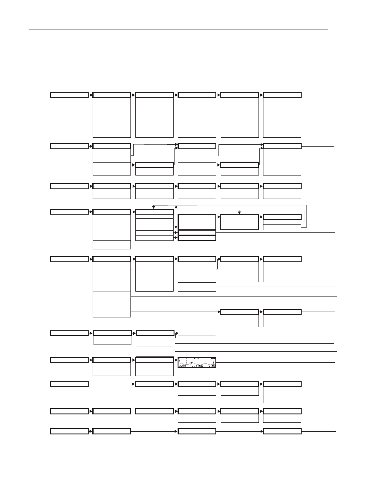
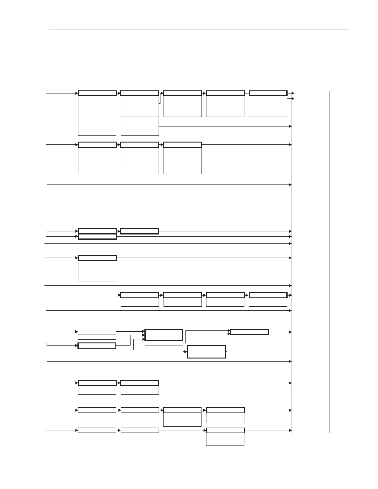
You can find an overview of all the device functions in the Appendix.
You can find a detailed description of all the device functions in the operating instructions
BA00388F/00/EN "Prosonic T - Description of Instrument Functions". This is located on the
supplied documentation CD-ROM.
F
L
D
E
… …
KA290F/00/A2/12.09
71106912
BD
… …
100%
0%
100
333
… …
… …
71106912
SD
Prosonic T - Quick Setup
- dome
ceiling
- horizontal
cyl.
- bypass
…
- unknown
- liquid
->4mm
-<4mm
(> 0.16 in)
( 0.16 in)
<
- standard
- calm
surface
- add. agitator
…
input E
(see sketch)
input F
(see sketch)
-ok
- too small
- too big
- unknown
- manual
displayed
(see sketch)
D and L are
confirm
or specify
range
suggestion
000
measured value
Group
selection
00
basic setup
01
safety settings
0C
system
parameter
0E
Envelope curve
04
linearisation
05
extended calibr.
06
output
0A
diagnostics
0A0
present
error
002
tank shape
004
process
cond.
005
empty
calibr.
006
full
calibr.
008
dist./
meas value
051
check
distance
003
medium
property
052
range of
mapping
053
start
mapping
008
dist./
meas value
0E1
plot settings
0E2
recording
curve
0A1
previous
error
0A4
unlock
parameter
03
temperature
09
display
092
language
BD: blocking distance
and : increase contrast
and : decrease contrast
0A3
reset
0C0
tag no.
SD: safety distance
Page 3

Prosonic T Table of contents
Endress+Hauser 3
Table of contents
1 Safety instructions . . . . . . . . . . . . . . . . 4
1.1 Designated use . . . . . . . . . . . . . . . . . . . . . . . . . . . . 4
1.2 Installation, commissioning, operation . . . . . . . . . . . 4
1.3 Operational safety and process safety . . . . . . . . . . . . 4
1.4 Notes on safety conventions and symbols . . . . . . . . . 5
2 Identification . . . . . . . . . . . . . . . . . . . . 6
2.1 Nameplate . . . . . . . . . . . . . . . . . . . . . . . . . . . . . . . 6
2.2 Product structure . . . . . . . . . . . . . . . . . . . . . . . . . . 7
2.3 Scope of delivery . . . . . . . . . . . . . . . . . . . . . . . . . . . 8
2.4 Certificates and approvals . . . . . . . . . . . . . . . . . . . . 8
2.5 Registered trademarks . . . . . . . . . . . . . . . . . . . . . . . 8
3 Installation . . . . . . . . . . . . . . . . . . . . . . 9
3.1 Design; dimensions . . . . . . . . . . . . . . . . . . . . . . . . . 9
3.2 Installation variants . . . . . . . . . . . . . . . . . . . . . . . . 10
3.3 Installation conditions . . . . . . . . . . . . . . . . . . . . . . 11
3.4 Measuring range . . . . . . . . . . . . . . . . . . . . . . . . . . 14
3.5 Installation hint . . . . . . . . . . . . . . . . . . . . . . . . . . . 15
3.6 Installation check . . . . . . . . . . . . . . . . . . . . . . . . . 15
4 Wiring . . . . . . . . . . . . . . . . . . . . . . . . 16
4.1 Electrical connection . . . . . . . . . . . . . . . . . . . . . . . 16
4.2 Terminal assignment . . . . . . . . . . . . . . . . . . . . . . . 17
4.3 Supply voltage . . . . . . . . . . . . . . . . . . . . . . . . . . . . 17
4.4 Potential matching . . . . . . . . . . . . . . . . . . . . . . . . 18
4.5 Checking the connection . . . . . . . . . . . . . . . . . . . . 18
5 Operation . . . . . . . . . . . . . . . . . . . . . . 19
5.1 Display and operating elements . . . . . . . . . . . . . . . 19
5.2 Function codes . . . . . . . . . . . . . . . . . . . . . . . . . . . 22
5.3 Operating options . . . . . . . . . . . . . . . . . . . . . . . . . 22
5.4 Operation using the on-site display . . . . . . . . . . . . 23
5.5 Operation using FieldCare . . . . . . . . . . . . . . . . . . . 24
5.6 Lock/unlock configuration . . . . . . . . . . . . . . . . . . 25
5.7 Resetting the customer parameters . . . . . . . . . . . . . 26
5.8 Resetting an interference echo suppression
(tank map) . . . . . . . . . . . . . . . . . . . . . . . . . . . . . . 26
6 Commissioning. . . . . . . . . . . . . . . . . . 27
6.1 Power up instrument . . . . . . . . . . . . . . . . . . . . . . . 27
6.2 Basic calibration . . . . . . . . . . . . . . . . . . . . . . . . . . 28
6.3 Envelope curve . . . . . . . . . . . . . . . . . . . . . . . . . . . 33
7 Troubleshooting . . . . . . . . . . . . . . . . . 36
7.1 System error messages . . . . . . . . . . . . . . . . . . . . . . 36
7.2 Application errors . . . . . . . . . . . . . . . . . . . . . . . . . 38
8 Maintenance and repairs . . . . . . . . . . 40
8.1 Exterior cleaning . . . . . . . . . . . . . . . . . . . . . . . . . . 40
8.2 Repairs . . . . . . . . . . . . . . . . . . . . . . . . . . . . . . . . . 40
8.3 Repairs to Ex-approved devices . . . . . . . . . . . . . . . 40
8.4 Replacement . . . . . . . . . . . . . . . . . . . . . . . . . . . . . 40
8.5 Spare Parts . . . . . . . . . . . . . . . . . . . . . . . . . . . . . . 41
8.6 Return . . . . . . . . . . . . . . . . . . . . . . . . . . . . . . . . . . 42
8.7 Disposal . . . . . . . . . . . . . . . . . . . . . . . . . . . . . . . . . 42
8.8 Contact addresses of Endress+Hauser . . . . . . . . . . . 42
9 Accessories . . . . . . . . . . . . . . . . . . . . . 43
9.1 Installation bracket . . . . . . . . . . . . . . . . . . . . . . . . 43
9.2 Screw in flange . . . . . . . . . . . . . . . . . . . . . . . . . . . 43
9.3 Cantilever with mounting frame or wall bracket . . . 44
9.4 Mounting Frame . . . . . . . . . . . . . . . . . . . . . . . . . . 46
9.5 Wall Bracket . . . . . . . . . . . . . . . . . . . . . . . . . . . . . 46
9.6 Commubox FXA291 . . . . . . . . . . . . . . . . . . . . . . . 47
9.7 ToF Adapter FXA291 . . . . . . . . . . . . . . . . . . . . . . . 47
10 Technical Data. . . . . . . . . . . . . . . . . . . 48
10.1 Technical data at a glance . . . . . . . . . . . . . . . . . . . 48
11 Appendix. . . . . . . . . . . . . . . . . . . . . . . 52
11.1 Operating menu . . . . . . . . . . . . . . . . . . . . . . . . . . 52
11.2 Measuring principle . . . . . . . . . . . . . . . . . . . . . . . . 54
Index . . . . . . . . . . . . . . . . . . . . . . . . . . . . . . 55
Page 4

Safety instructions Prosonic T
4 Endress+Hauser
1 Safety instructions
1.1 Designated use
The Prosonic T is a compact measuring device for continuous, non-contact level measurement.
Depending on the sensor, the measuring range is up to 8 m (26 ft) in fluids and up to 3.5 m (11 ft)
in bulk solids.
1.2 Installation, commissioning, operation
The instrument is fail-safe and is constructed to the state-of-the-art. It meets the appropriate
standards and EC directives. However, if you use it improperly or other than for its designated use,
it may pose application-specific hazards, e.g. product overflow due to incorrect installation or
configuration. Installation, electrical connection, start-up, operation and maintenance of the
measuring device must therefore be carried out exclusively by trained specialists authorised by the
system operator. Technical personnel must have read and understood these operating instructions
and must adhere to them. You may only undertake modifications or repair work to the device when
it is expressly permitted by the operating instructions.
1.3 Operational safety and process safety
Alternative monitoring measures must be taken to ensure operational safety and process safety
during configuration, testing and maintenance work on the device.
Hazardous areas
Measuring systems for use in hazardous environments are accompanied by separate "Ex
documentation", which is an integral part of this Operating Manual. Strict compliance with the
installation instructions and ratings as stated in this Additional documentation is mandatory.
• Ensure that all personnel are suitably qualified.
• Observe the specifications in the certificate as well as national and local regulations.
Page 5

Prosonic T Safety instructions
Endress+Hauser 5
1.4 Notes on safety conventions and symbols
In order to highlight safety-relevant or alternative operating procedures in the manual, the following
conventions have been used, each indicated by a corresponding symbol in the margin.
Safety conventions
#
Warning!
A warning highlights actions or procedures which, if not performed correctly, will lead to personal
injury, a safety hazard or destruction of the instrument
"
Caution!
Caution highlights actions or procedures which, if not performed correctly, may lead to personal
injury or incorrect functioning of the instrument
!
Note!
A note highlights actions or procedures which, if not performed correctly, may indirectly affect
operation or may lead to an instrument response which is not planned
Explosion protection
0
Device certified for use in explosion hazardous area
If the device has this symbol embossed on its name plate it can be installed in an explosion hazardous
area
-
Explosion hazardous area
Symbol used in drawings to indicate explosion hazardous areas. Devices located in and wiring
entering areas with the designation “explosion hazardous areas” must conform with the stated type
of protection.
.
Safe area (non-explosion hazardous area)
Symbol used in drawings to indicate, if necessary, non-explosion hazardous areas. Devices located in
safe areas still require a certificate if their outputs run into explosion hazardous areas
Electrical symbols
%
Direct voltage
A terminal to which or from which a direct current or voltage may be applied or supplied
&
Alternating voltage
A terminal to which or from which an alternating (sine-wave) current or voltage may be applied or
supplied
)
Grounded terminal
A grounded terminal, which as far as the operator is concerned, is already grounded by means of an
earth grounding system
*
Protective grounding (earth) terminal
A terminal which must be connected to earth ground prior to making any other connection to the
equipment
+
Equipotential connection (earth bonding)
A connection made to the plant grounding system which may be of type e.g. neutral star or
equipotential line according to national or company practice
Page 6
Identification Prosonic T
6 Endress+Hauser
2 Identification
2.1 Nameplate
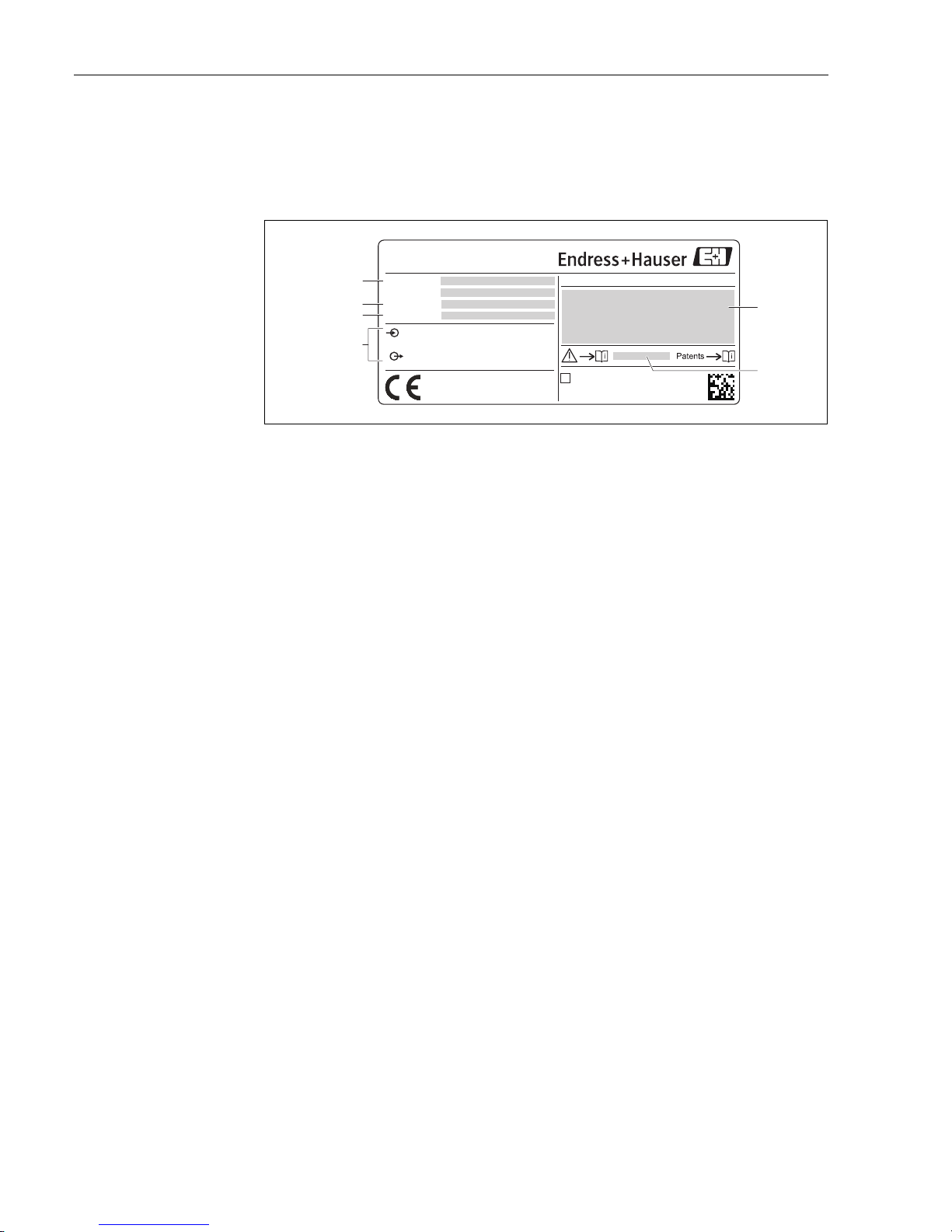
L00-FMU30xxx-18-00-00- xx-001
1 Designation according to Directive 94/9/EC and designation of the type of protection
(only for certified device variants)
2 Reference to additional safety-relevant documentation (only for certified device variants)
3 Supply voltage
4 Serial number
5Ident-No.
6 Order Code
Prosonic T
Order Code:
4 ... 20 mA
Made in Germany,D- 79689 Maulburg
Ser.No.:
Ident.-No.:
14 ... 35 V DC 0.8 W
IP68
Dat/Insp.:
250002891--
2-wire
if modification
see sep. label
X=
6
3
1
4
5
2
Page 7
Prosonic T Identification
Endress+Hauser 7
2.2 Product structure
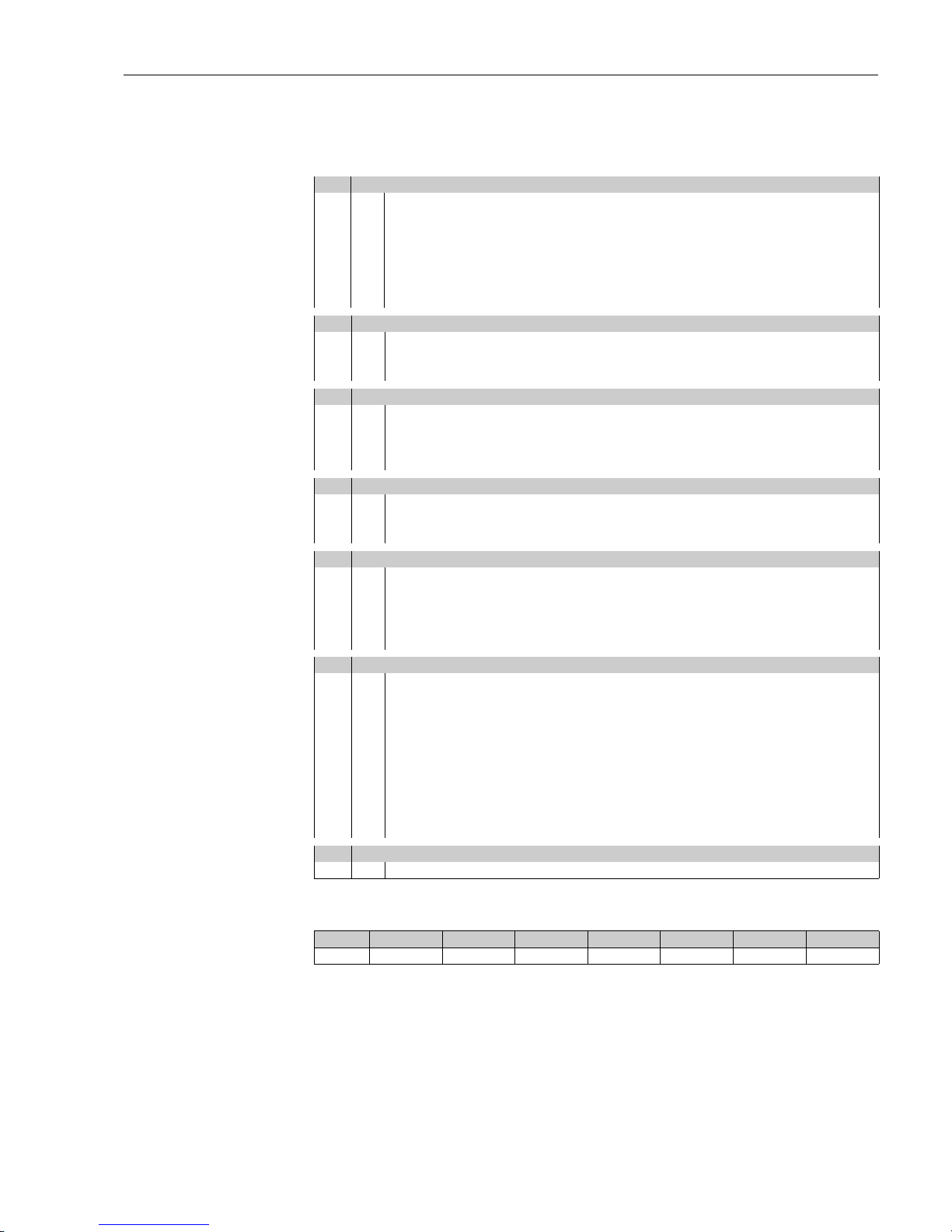
Versions that mutually exclude one another are not marked.
You can fill in the options of the respective feature into the following table. The filled in options
result in the complete order code.
010 Approval:
AA Non-hazardous area
BB ATEX II 1/2G Ex ia IIC T5
CA CSA C/US General Purpose
CB CSA C/US IS CI.I Div.1 Gr.A-D
IB IEC Ex zone 0/1, Ex ia IIC T5 Ga/Gb
NB NEPSI zone 0/1, Ex ia IIC T5 Ga/Gb
99 Special version
020 Display; Operating:
G W/o; via spare part display FMU30
H Envelope curve display on site; push button
Y Special version
030 Electrical Connection:
E Gland M20, IP68
F Thread G1/2, IP68
G Thread NPT1/2, IP68
YSpecial version
040 Sensor; Max Range; Blocking Distance:
AA 1-1/2"; 5m liquid/2m solid; 0.25m
AB 2"; 8m liquid/3.5m solid; 0.35m
YY Special version
050 Process Connection:
GGF Thread ISO228 G1-1/2, PP
GHF Thread ISO228 G2, PP
RGF Thread ANSI MNPT1-1/2, PP
RHF Thread ANSI MNPT2, PP
YYY Special version
620 Accessory Enclosed:
RA UNI flange 2"/DN50/50, PP max 4bar abs/58psia, suitable for 2" 150lbs/DN50 PN16/10K 50
RB UNI flange 2"/DN50/50, PVDF max 4bar abs/58psia, suitable for 2" 150lbs/DN50 PN16/10K 50
RC UNI flange 2"/DN50/50, 316L max 4bar abs/58psia, suitable for 2" 150lbs/DN50 PN16/10K 50
RD UNI flange 3"/DN80/80, PP max 4bar abs/58psia, suitable for 3" 150lbs/DN80 PN16/10K 80
RE UNI flange 3"/DN80/80, PVDF max 4bar abs/58psia, suitable for 3" 150lbs/DN80 PN16/10K 80
RF UNI flange 3"/DN80/80, 316L max 4bar abs/58psia, suitable for 3" 150lbs/DN80 PN16/10K 80
RG UNI flange 4"/DN100/100, PP max 4bar abs/58psia, suitable for 4" 150lbs/DN100 PN16/10K 100
RH UNI flange 4"/DN100/100, PVDF max 4bar abs/58psia, suitable for 4" 150lbs/DN100 PN16/10K 100
RI UNI flange 4"/DN100/100, 316L max 4bar abs/58psia, suitable for 4" 150lbs/DN100 PN16/10K 100
R9 Special version
895 Marking:
Z1 Tagging (TAG), see additional spec.
010 020 030 040 050 620 895
FMU30 -
Page 8

Identification Prosonic T
8 Endress+Hauser
2.3 Scope of delivery
• Instrument according to the version ordered
• Accessories ( ä 43)
• Brief operating instructions KA01054F/00/EN for quick commissioning
• Brief operating instructions KA00290F/00/A2 (basic setup/troubleshooting), housed in the
instrument)
• For certified instrument versions: Safety Instructions, Control- or Installation drawings
• counter nut (PC): option 50, versions GGF/GHF ä 7 "Product structure"
• sealing ring (EPDM): option 50, versions GGF/GHF ä 7 "Product structure"
• for gland M20x1.5: cable gland
The cable gland is mounted on delivery.
• CD-ROM with further documentation, e. g.
- Technical Information
- Operating Instructions
- Description of Intrument Functions
2.4 Certificates and approvals
CE mark, declaration of conformity
The device is designed to meet state-of-the-art safety requirements, has been tested and left the
factory in a condition in which it is safe to operate. The device complies with the applicable
standards and regulations as listed in the EC declaration of conformity and thus complies with the
statutory requirements of the EC directives. Endress+Hauser confirms the successful testing of the
device by affixing to it the CE mark.
2.5 Registered trademarks
FieldCare
®
Trademark of Endress+Hauser Process Solutions AG.
ToF
®
Registered trademark of the company Endress+Hauser GmbH+Co. KG, Maulburg, Germany
PulseMaster
®
Trademark of the company Endress+Hauser GmbH+Co. KG, Maulburg, Germany
Page 9
Prosonic T Installation
Endress+Hauser 9
3 Installation
3.1 Design; dimensions
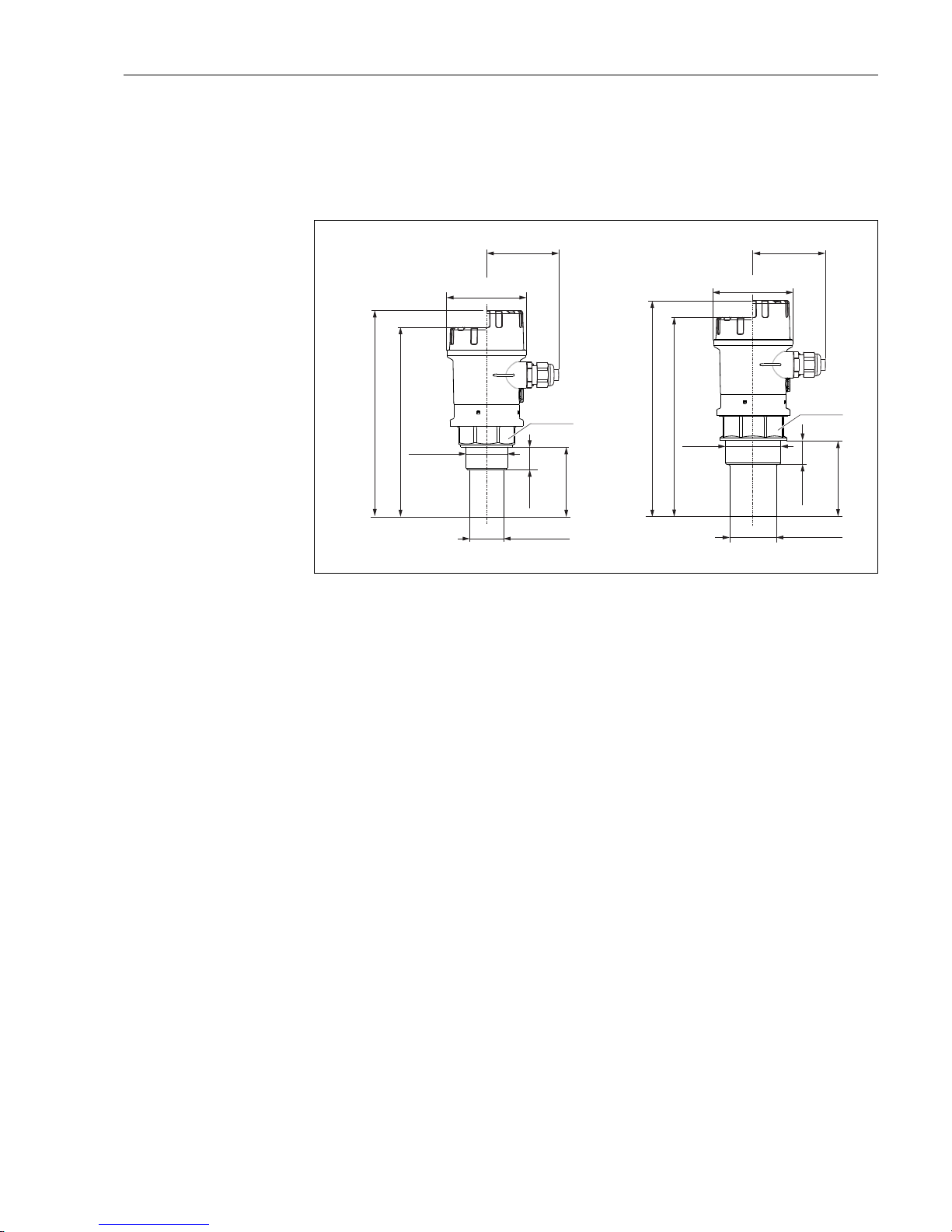
L00-FMU30xxx-06-00-00-xx-006
A Sensor 1½"
B Sensor 2"
G 1½”
1½NPT ”
SW65
(AF65)
234 (9.21)
mm (in)
81 (3.19)
82
(3.23)
26
(1.02)
ø50 (1.97)
238 (9.37)
SW65
(AF65)
G 2”
2NPT ”
215 (8.46)
220 (8.66)
ø39 (1.54)
26
(1.02)
ø85 ( 3.35)ø
max. 76
(2.99)
max. 76
(2.99)
ø85 ( 3.35)ø
AB
Page 10
Installation Prosonic T
10 Endress+Hauser
3.2 Installation variants
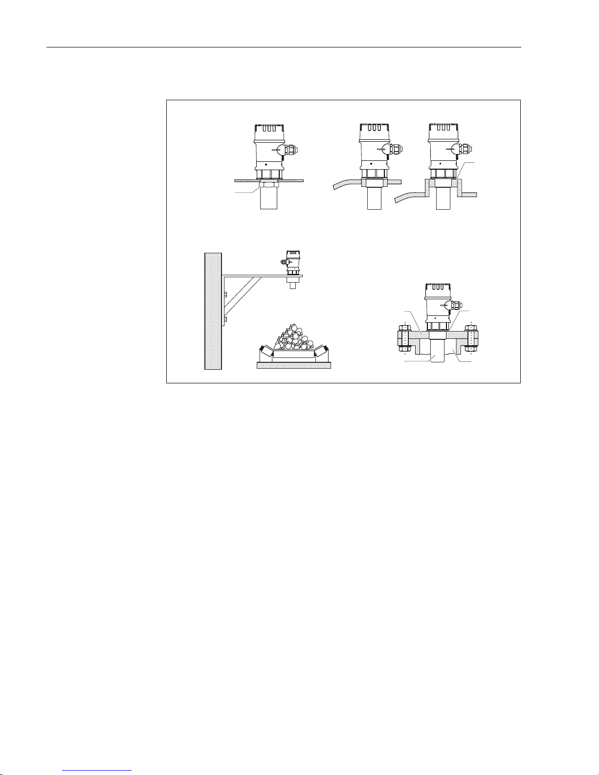
L00-FMU30xxx-17-00-00- xx-002
A Installation with counter nut
1 counter nut (PC) supplied for G1½ and G2 instruments
B Installation with sleeve
1 sealing (EPDM) supplied
C Installation with installation bracket
D Installation with screw in flange
1 sealing (EPDM) supplied
2 nozzle
3sensor
4 screw in flange
For installation bracket or screw in flange ä 43, "Accessories".
BA
C
D
1
1
1
2
3
4
Page 11
Prosonic T Installation
Endress+Hauser 11
3.3 Installation conditions
3.3.1 Installation conditions for level measurements
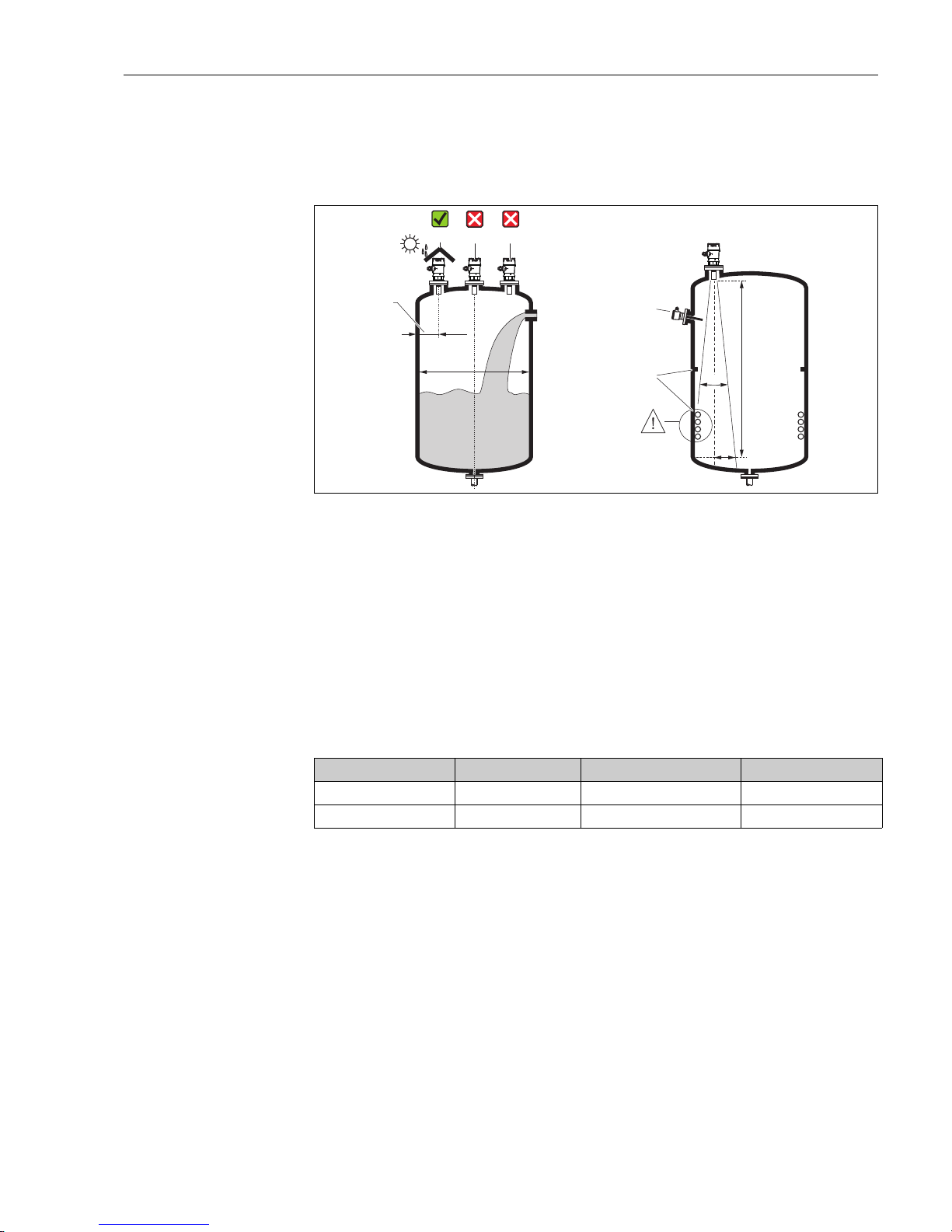
L00-FMU30xxx-17-00-00-xx-005
• Do not install the sensor in the middle of the tank (3). We recommend leaving a distance between
the sensor and the tank wall (1) measuring 1/6 of the tank diameter.
• Protect the device against direct sun or rain (2), e.g. with a weather protection cover, see the
technical information TI00440F, chapter "Accessories".
• Avoid measurements through the filling curtain (4).
• For solid application where bulk solid cones appear, align the sensor membrane perpendicular to
the surface.
• Make sure that equipment (5) such as limit switches, temperature sensors, etc. are not located
within the emitting angle . In particular, symmetrical equipment (6) such as heating coils, baffles
etc. can influence measurement.
• Never install two ultrasonic measuring devices in a tank, as the two signals may affect each other.
• To estimate the detection range, use the 3 dB emitting angle .
1
234
5
6
1/6D
D
r
a
L
Sensor L
max
r
max
1½" 11° 5 m (16 ft) 0.48 m (1.6 ft)
2" 11° 8 m (26 ft) 0.77 m (2.5 ft)
Page 12
Installation Prosonic T
12 Endress+Hauser
3.3.2 Installation in narrow shafts
3.3.3 Installation conditions for flow measurements
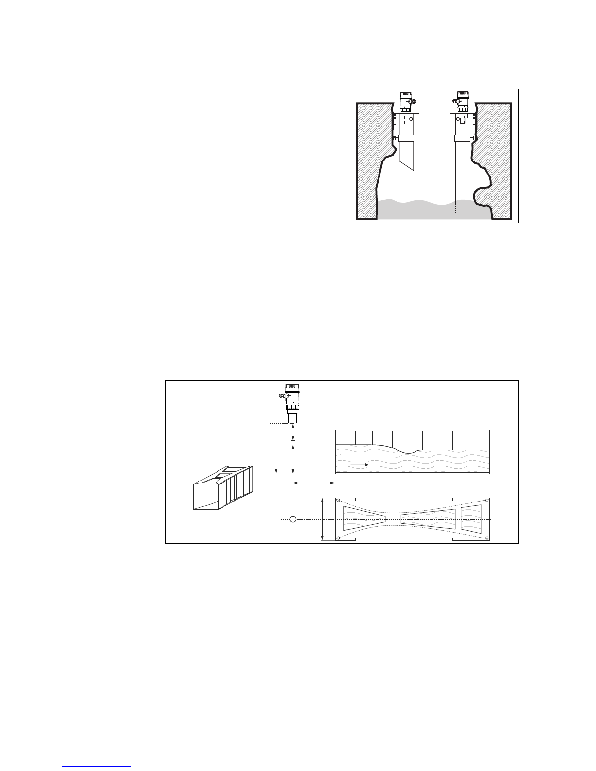
• Install the device at the inflow side (B), as close above the maximum water level H
max
as possible
(take into account the blocking distance BD).
• Position the instrument in the middle of the channel or weir.
• Align the sensor membrane parallel to the water surface.
• Keep to the installation distance of the channel or weir.
Example: Khafagi-Venturi flume
A0019607
A Khafagi-Venturi flume BD Blocking distance
B Inflow E Empty calibration
C Outflow F Full calibration
V Direction of flow
In narrow shafts with strong interference
echoes, we recommend using an ultrasound
guide pipe (e.g. PE or PVC wastewater pipe)
with a minimum diameter of 100 mm (3.94 in).
Make sure that the pipe is not soiled by accumulated dirt. If necessary, clean the pipe at regular
intervals.
L00-FMU30xxx-17-00-00- xx-010
1 Venting hole
1
1 x b
0
b
0
BD
A
E
BC
V
H
max
=F
Page 13
Prosonic T Installation
Endress+Hauser 13
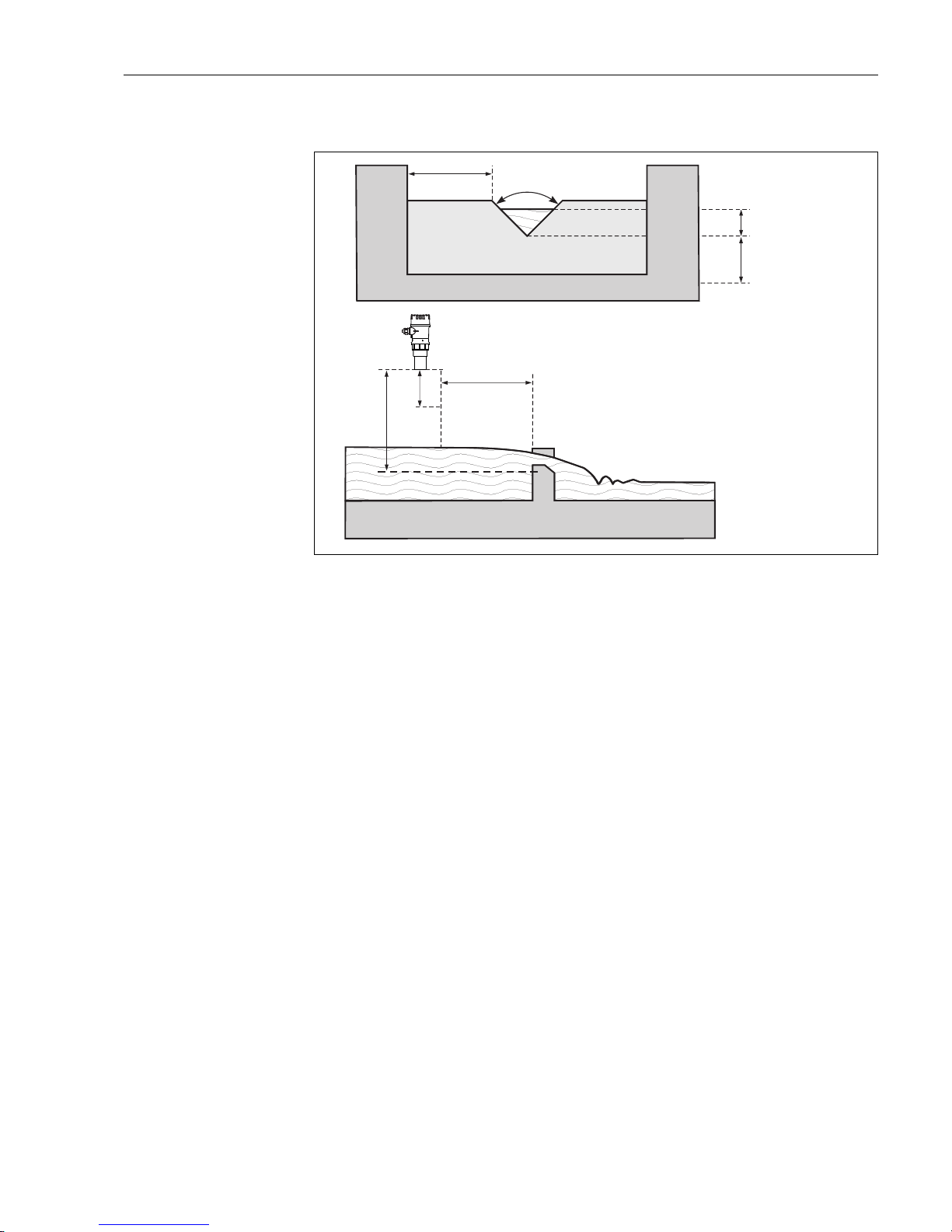
Example: Triangular weir
L00-FMU30xxx-17-00-00-xx-012
BD Blocking distance
E Empty calibration
F Full calibration
min. 3 H
H
min. 2 H
a
min. 2 H
BD
max
max
max
max
E
(= F)
Page 14
Installation Prosonic T
14 Endress+Hauser
3.4 Measuring range
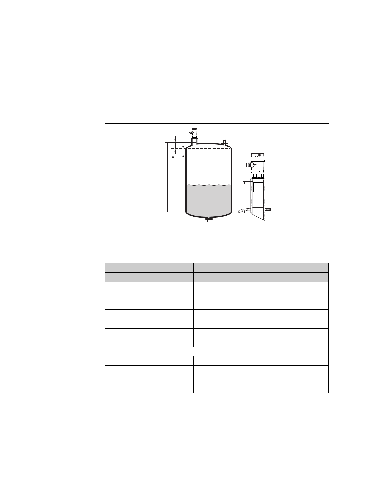
3.4.1 Blocking distance, Nozzle mounting
Install the instrument at a height so that the blocking distance BD is not undershot, even at
maximum fill level. Use a pipe nozzle if you cannot maintain the blocking distance in any other way.
The interior of the nozzle must be smooth and may not contain any edges or welded joints. In
particular, there should be no burr on the inside of the tank side nozzle end. Note the specified limits
for nozzle diameter and length. To minimise disturbing factors, we recommend an angled socket
edge (ideally 45°).
L00-FMU30xxx-17-00-00- xx-004
BD Blocking distance F Full calibration (span)
SD Safety distance D Nozzle diameter
E Empty calibration L Nozzle length
"
Caution!
If the blocking distance is undershot, it may cause device malfunction.
!
Note!
In order to notice if the level approaches the blocking distance, you can specify a safety distance
(SD). If the level is within this safety distance, the instrument outputs a warning or alarm message.
F
E
BD
SD
L
D
Maximum nozzle length mm (in)
Nozzle diameter 1½" sensor 2" sensor
DN50/2" 80 (3.15)
DN80/3" 240 (9.45) 240 (9.45)
DN100/4" 300 (11.8) 300 (11.8)
DN150/6" 400 (15.7) 400 (15.7)
DN200/8" 400 (15.7) 400 (15.7)
DN250/10" 400 (15.7) 400 (15.7)
DN300/12" 400 (15.7) 400 (15.7)
Sensor characteristics
Emitting angle 11° 11°
Blocking distance (m [ft]) 0.25 (0.8) 0.35 (1.1)
Max. range (m [ft]) in liquids 5 (16) 8 (26)
Max. range (m [ft]) in solids 2 (6.6) 3.5 (11)
Page 15

Prosonic T Installation
Endress+Hauser 15
3.4.2 Safety distance
If the level rises to the safety distance SD, the device switches to warning or alarm status.
The size of SD can be set freely in the "Safety distance" (015) function.The "in safety distance"
(016) function defines how the device reacts if the level enters the safety distance.
There are three options:
• Warning: The device outputs an error message but continues measurement.
• Alarm: The device outputs an error message. The output signal assumes the value defined in the
"Output on alarm" (011) function (MAX, MIN, user-specific value or holds the last value). As
soon as the level drops below the safety distance, the device recommences measurement.
• Self holding: The device reacts in the same way as for an alarm. However, the alarm condition
continues after the level drops below the safety distance. The device only recommences
measurement when you cancel the alarm using the "Ackn. alarm" (017) function.
3.4.3 Range
The sensor range is dependent on the measuring conditions. Refer to Technical Information
TI00440F/00/EN for an estimation. The maximum range is shown in the above diagram (valid for
good conditions).
3.5 Installation hint
3.6 Installation check
After installing the device, carry out the following checks:
• Is the device damaged (visual inspection)?
• Does the device correspond to the measuring point specifications for process temperature, process
pressure, ambient temperature, measuring range etc.
• If available: Are the measuring point number and labelling correct (visual inspection)?
• Is the measuring device sufficiently protected against precipitation and direct sunlight?
• Are the cable glands tightened correctly?
• After aligning the housing, check the process seal at the nozzle or flange.
Sensor Maximum range
1½" 5 m (16 ft)
2" 8 m (26 ft)
"
Caution!
Use only the screw-in piece to screw in the
Prosonic T.
Screw the instrument at the screw-in piece
using an 65AF spanner.
L00-FMU30xxx-17-00-00-xx-009
1 65 AF, max. torque 7 Nm (5.16 lbf ft)
65
1
Page 16
Wiring Prosonic T
16 Endress+Hauser
4 Wiring
4.1 Electrical connection
"
Caution!
Before connection please note the following:
• The power supply must be identical to the data on the nameplate.
• Switch off power supply before connecting up the instrument.
• Connect equipotential bonding to devices ground terminal before connecting up the instrument
ä 18, "Potential matching".
#
Warning!
When you use the measuring system in hazardous areas, make sure to comply with national
standards and the specifications in the safety instructions (XA’s). Make sure you use the specified
cable gland.
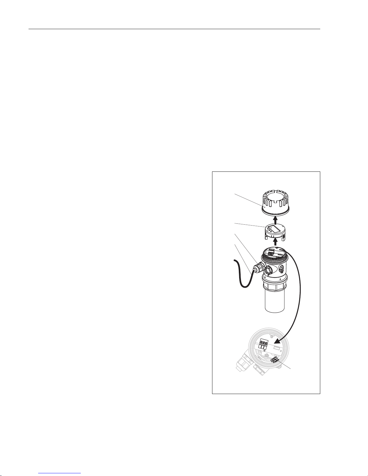
4.1.1 Wiring
1. Unscrew housing cover (1).
2. Remove display (2) if fitted.
3. Insert cable (3) through gland (4).
"
Caution!
If possible, insert the cable from above and
let a draining loop in order to avoid
intrusion of humidity.
4. Installation cable screen to the grounding
terminal (5) within the terminal
compartment.
5. Make connection according to terminal
assignment, ä 17, "Terminal
assignment".
6. Tighten cable gland (4).
7. Insert display (2) if fitted.
8. Screw on housing cover (1).
9. Switch on power supply.
L00-FMU30xxx-04-00-00- xx-008
1
2
1
2
3
5
4
Page 17
Prosonic T Wiring
Endress+Hauser 17
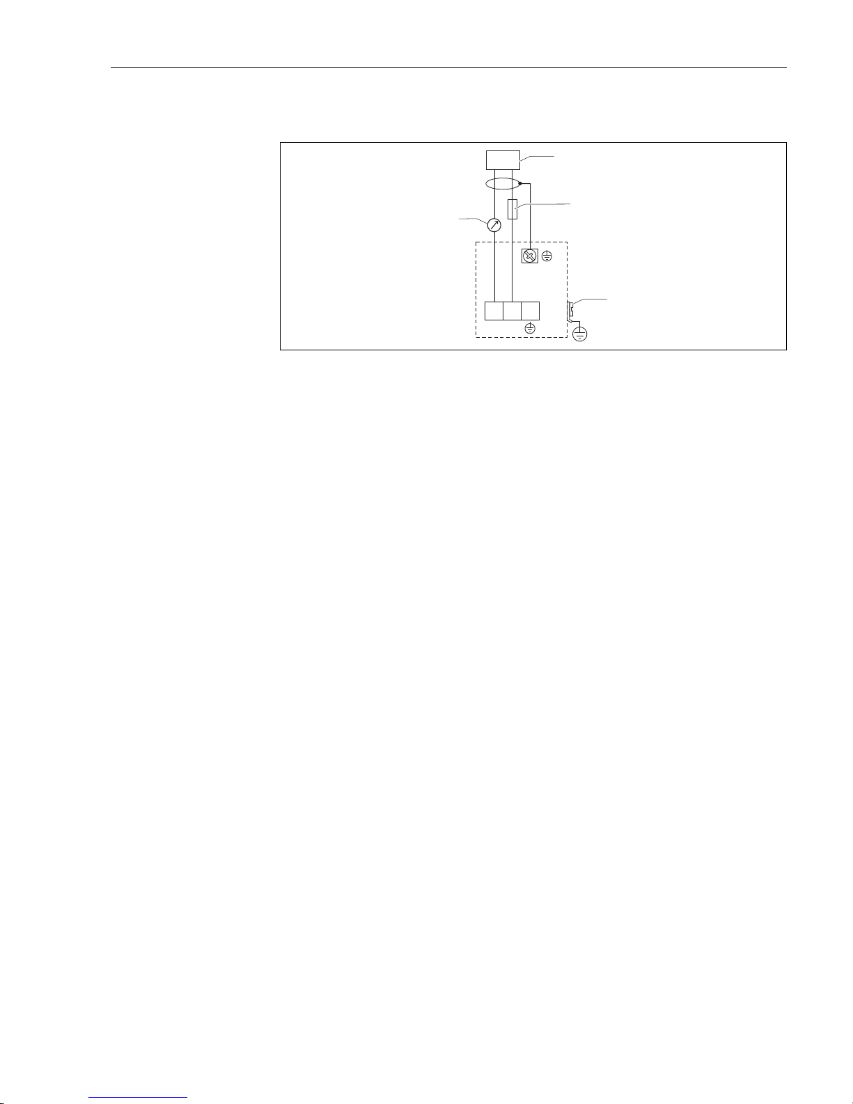
4.2 Terminal assignment
L00-FMU30xxx-04-00-00-de-015
1Power
2 Fuse as per IEC 60127, T 0.5 A
3 Plant ground
3 4...20 mA
4.3 Supply voltage
The voltages across the terminals directly at the instrument: 14-35 V
L-
L+
123
1
3
4
2
T 0.5A
Page 18
Wiring Prosonic T
18 Endress+Hauser
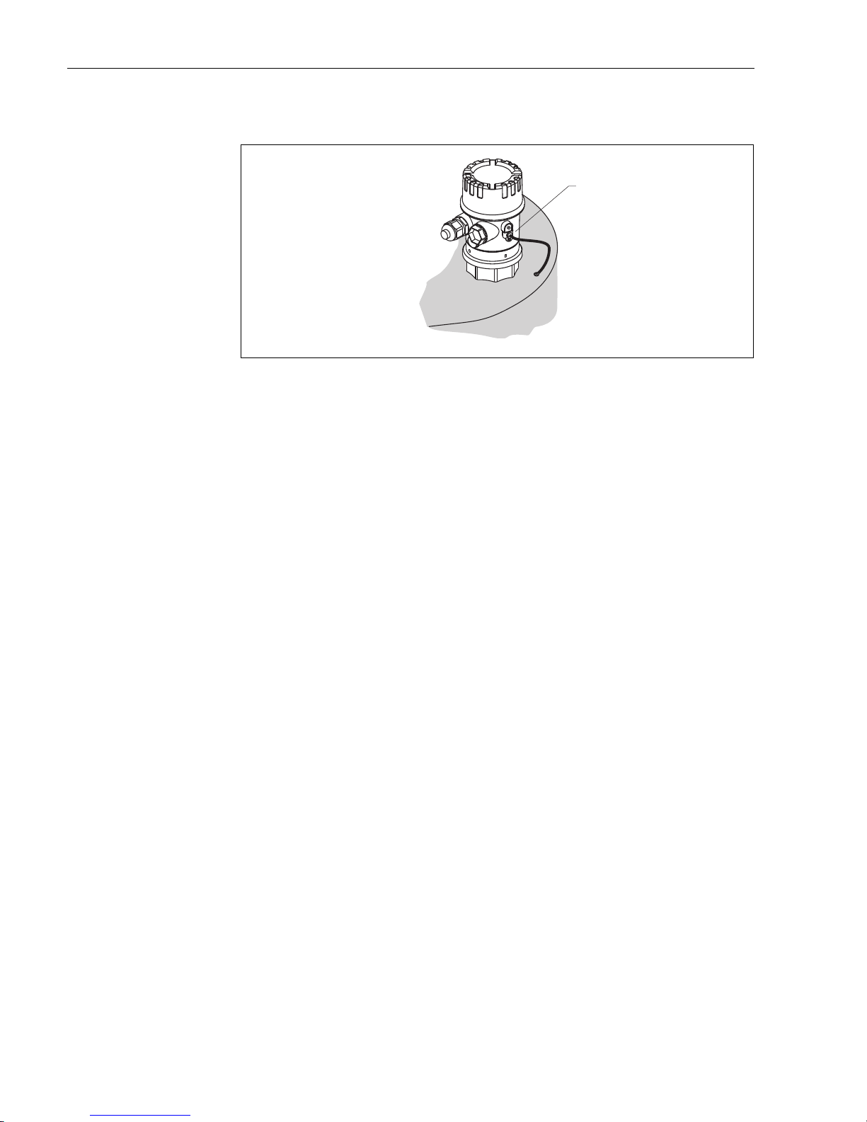
4.4 Potential matching
L00-FMU30xxx-17-00-00- xx-014
1 External ground terminal of the device
Connect the equipotential bonding to the external ground terminal of the device.
"
Caution!
In Ex applications, the instrument must only be grounded on the sensor side. Further safety
instructions are given in the separate documentation for applications in explosion hazardous areas.
!
Note!
Since the housing is isolated from the tank by the plastic sensor, interference signals may occur if
the potential matchin gline is not prolerly connected.
For optimum electromagnetic compatibility the potential matching line should be as short as
possible and at least 2.5 mm
2
(14 AWG) in cross-section.
If increased electromagnetic interference is to be expected due to the installation conditions, we
recommend usage of a ground strap.
4.5 Checking the connection
After wiring the device, carry out the following checks:
• Are the terminals correctly assigned?
• Is the cable gland tight?
• Is the housing cover fully screwed on?
• If power supply available: Does a display appear on the display module?
1
Page 19
Prosonic T Operation
Endress+Hauser 19
5Operation
5.1 Display and operating elements
5.1.1 On-site display
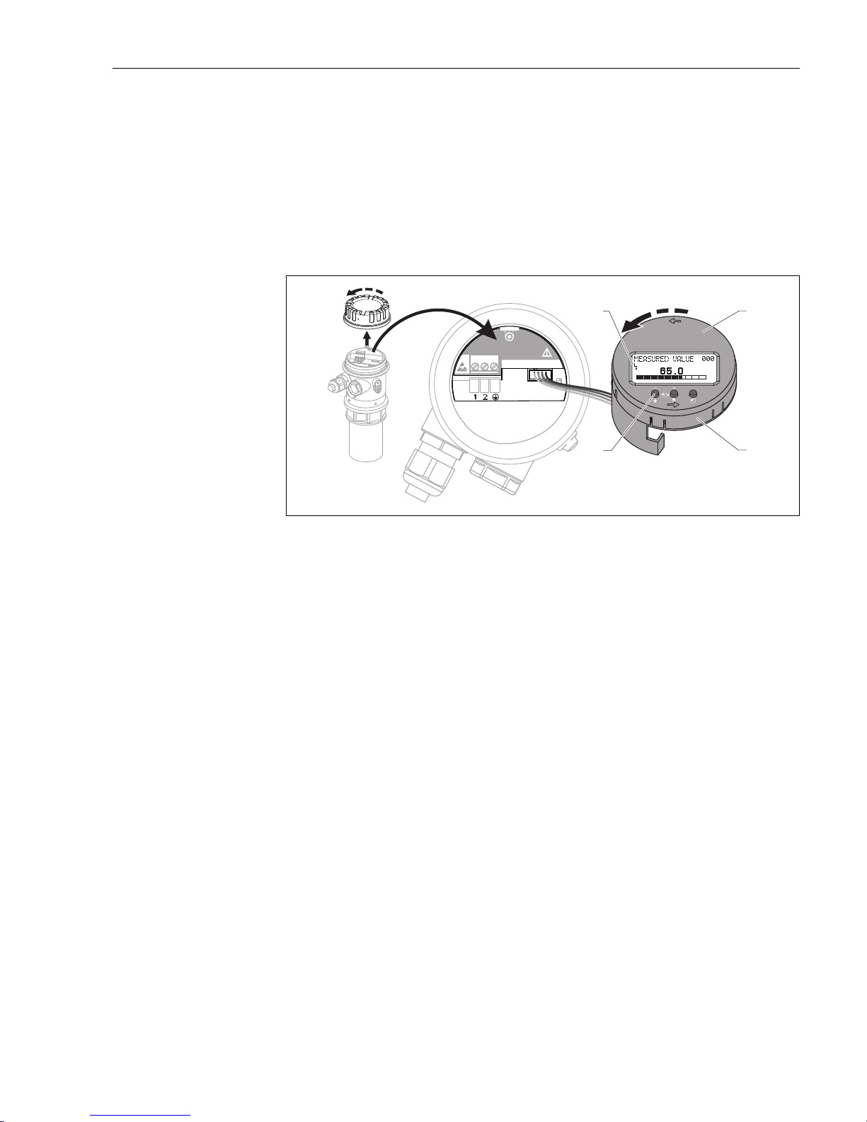
The LCD module for display and operation is located beneath the housing cover. The measured
value is legible through the transparent cover. Open the cover to operate the device.
L00-FMU30xxx-07-05-xx-xx-000
1 Display symbol
2 Display (rotatable)
3 Plug-in module
4 Function keys
4...20mA
+
FEU31
-
Display
%
E
1
2
3
4
Page 20
Operation Prosonic T
20 Endress+Hauser
5.1.2 Display appearance
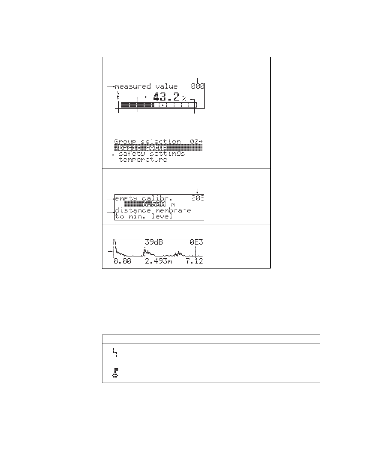
In the measured value display, the bargraph corresponds to the output.
The bargraph is segmented in 10 bars. Each completely filled bar represents a change of 10% of the
adjusted span.
5.1.3 Display symbols
The following table describes the symbols that appear on the liquid crystal display:
measured value display
1. label
2. symbol
3. value
4. bargraph
5. unit
6. position in menu
group selection
1. selection list
Function with free parameter
1. label
2. help texts
3. position in menu
envelope curve
1. envelope curve
Sybmol Meaning
ALARM_SYMBOL
This alarm symbol appears when the instrument is in an alarm state. If the symbol flashes, this indicates a
warning.
LOCK_SYMBOL
This lock symbol appears when the instrument is locked, i.e. if no input is possible.
4
1
6
3
5
2
1
2
1
3
1
Page 21
Prosonic T Operation
Endress+Hauser 21
5.1.4 Function of the keys
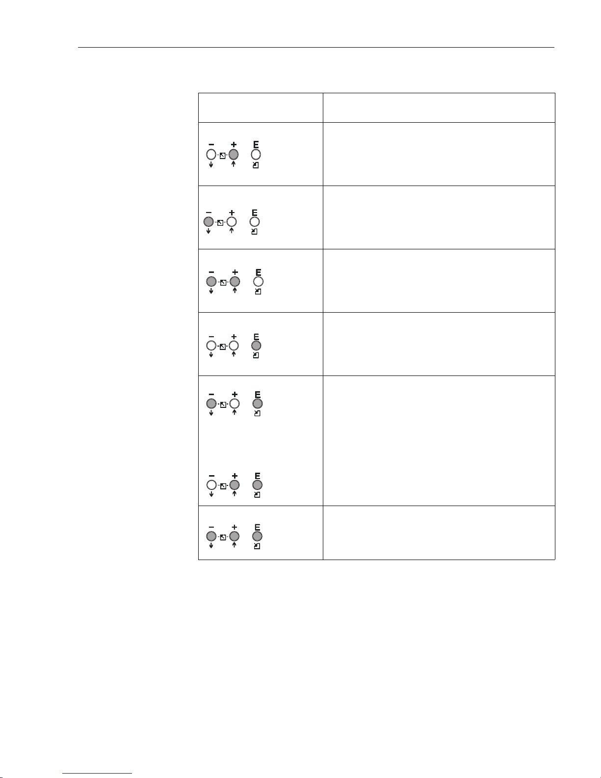
Key(s) Meaning
(The keys to press are displayed in grey.)
Navigate upwards in the selection list
Edit numeric value within a function
Navigate downwards in the selection list
Edit numeric value within a function
Navigate to the left within a function group
Navigate to the right within a function group, confirmation.
or Contrast settings of the LCD
Hardware lock / unlock
After a hardware lock, an operation of the instrument via display or
communication is not possible!
The hardware can only be unlocked via the display. An unlock parameter must
be entered to do so.
Page 22
Operation Prosonic T
22 Endress+Hauser
5.2 Function codes
For easy orientation within the function menus, for each function a position is shown on the display.
The first two digits identify the function group:
The third digit numbers the individual functions within the function group:
Hereafter the position is always given in brackets (e.g. "tank shape" (002)) after the described
function.
5.3 Operating options
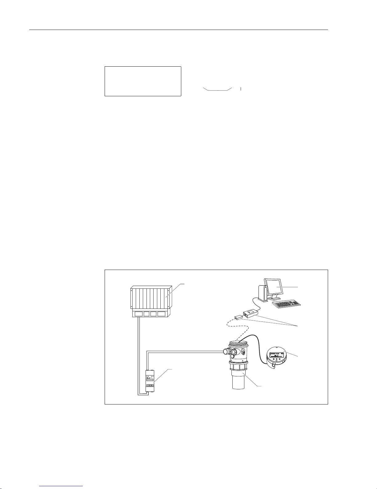
The complete measuring system consists of:
L00-FMU30xxx-14-00-06- xx-008
1 PLC (programmable logic controller)
2 Computer with operating tool (e.g. FieldCare)
3 Commubox FXA291 and ToF Adapter FXA291
4 Operating and display module
5 Prosonic FMU30
6 Transmitter power supply unit RMA42 or RN221N
empty calibr. 005
6.500 m
distance membrane
to min. level
1 Function group
2 Function
• basic setup 00
• safety settings 01
• temperature 03
. . .
• basic setup 00 • tank shape 002
• medium property 003
• process cond. 004
. . .
2
005
1
ENDRESS+HAUSER
RMA422
%
E
1
2
3
4
5
6
Page 23
Prosonic T Operation
Endress+Hauser 23
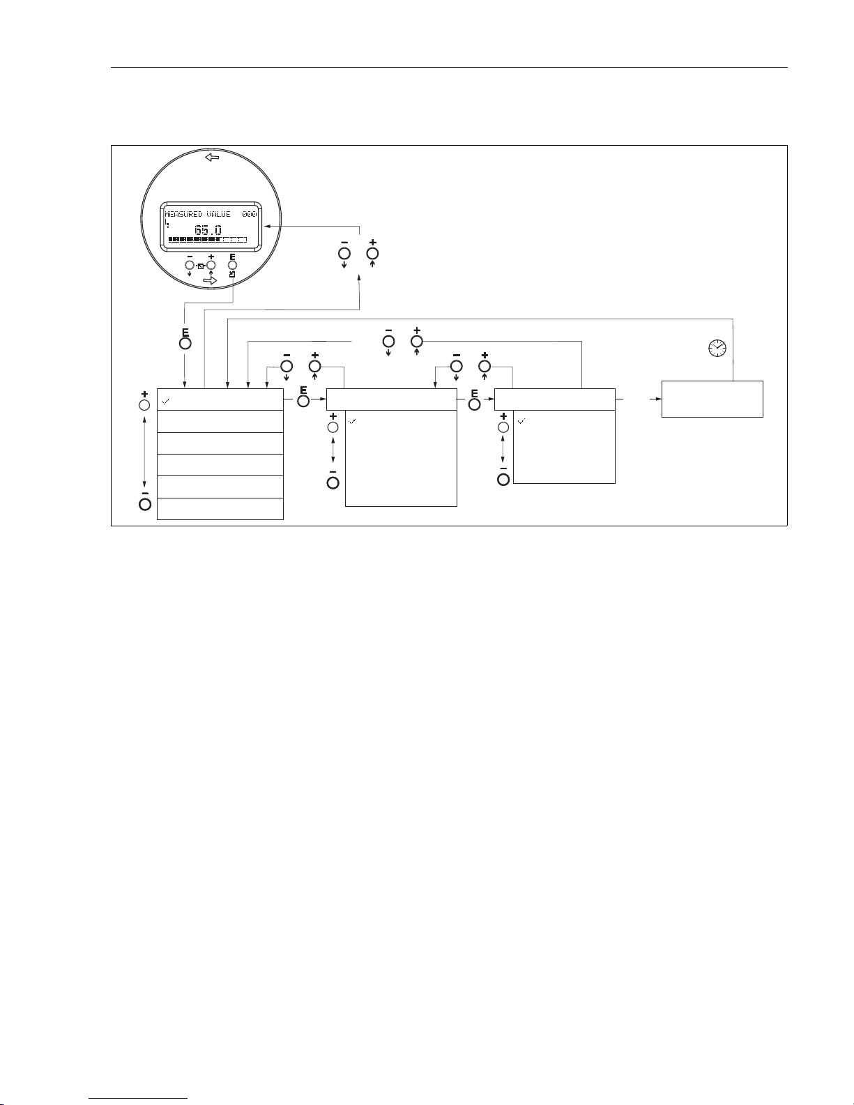
5.4 Operation using the on-site display
L00-FMU30xxx-19-00-00-en-018
1. Change from Measured Value Display to Group Selection by pressing E.
2. Press - or + to select the required Function Group and confirm by pressing E.
The active selection is marked by a ✓ in front of the menu text.
3. Activate Edit mode with + or - .
Selection menus
a. Select the required Parameter in selected function with - oder + .
b. E confirms selection; ✓appears in front of the selected parameter.
c. E confirms the edited value; system quits edit mode.
d. + and - interrupts selection; system quits edit mode.
Typing in numerals and text
a. Press + or - to edit the first character of the numeral / text.
b. E positions the cursor at the next character; continue with a. until you have completed your
input.
c. If a symbol appears at the cursor, press E to accept the value entered; system quits edit
mode.
d. If a symbol appears at the cursor, press E to return to the previous character (e.g. for
correction of entries).
e. + and - interrupts selection; system quits edit mode.
4. Press E to select the next function.
5. Press + and - once; return to previous function.
Press + and - twice; return to Group Selection.
6. Press + and - to return to Measured value display.
>3 s
...
2x
...
...
unknown
liquid
solid<4mm
solid>4mm
Return to
Group Selection
basic setup
safety settings
temperature
linearisation
tank shape
dome ceiling
horizontal cyl
bypass
stilling well
flat ceiling
sphere
no ceiling
medium property
%
Page 24
Operation Prosonic T
24 Endress+Hauser
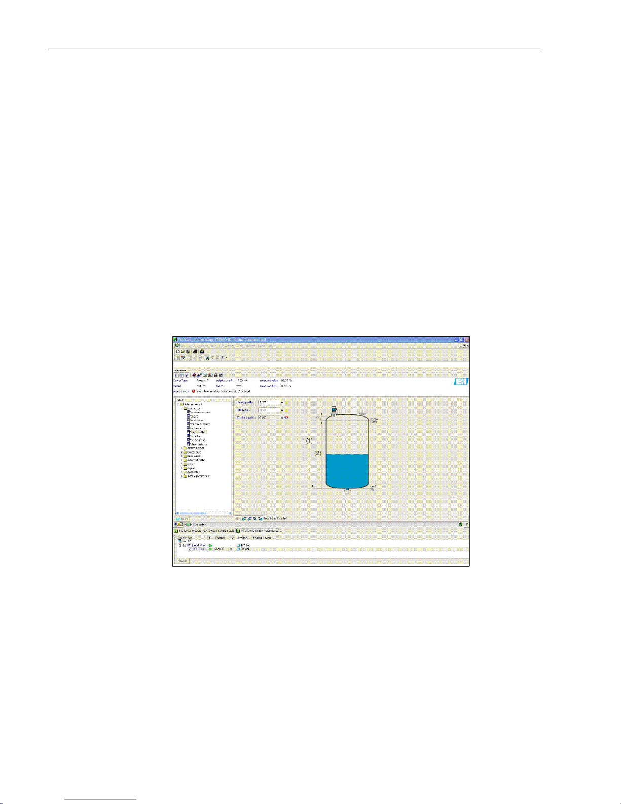
5.5 Operation using FieldCare
FieldCare is Endress+Hauser's FDT based Plant Asset Management Tool. It can configure all
intelligent field devices in your plant and supports you in managing them. By using status
information, it also provides a simple but effective means of checking their health.
• Supports Ethernet, HART, PROFIBUS, FOUNDATION Fieldbus etc.
• Operates all Endress+Hauser devices
• Operates all third-party actuators, I/O systems and sensors supporting the FDT standard
• Ensures full functionality for all devices with DTMs
• Offers generic profile operation for any third-party fieldbus device that does not have a vendor
DTM
Connection for FMU30:
• Commubox FXA291 and ToF adapter FXA291 (available as accessory)
Using the following functions:
• Signal analysis via envelope curve
• Linearisation table (graphically supported creation, editing, importing and exporting)
• Loading and saving of instrument data (Upload/Download)
• Documentation of measuring point
5.5.1 Menu guided commissioning
• You can find the function groups and functions of the device in the navigation bar.
• You can find the input fields for the parameters in the main window.
• If you click on a parameter name, the Help pages open with precise explanations of the required
input.
Page 25
Prosonic T Operation
Endress+Hauser 25
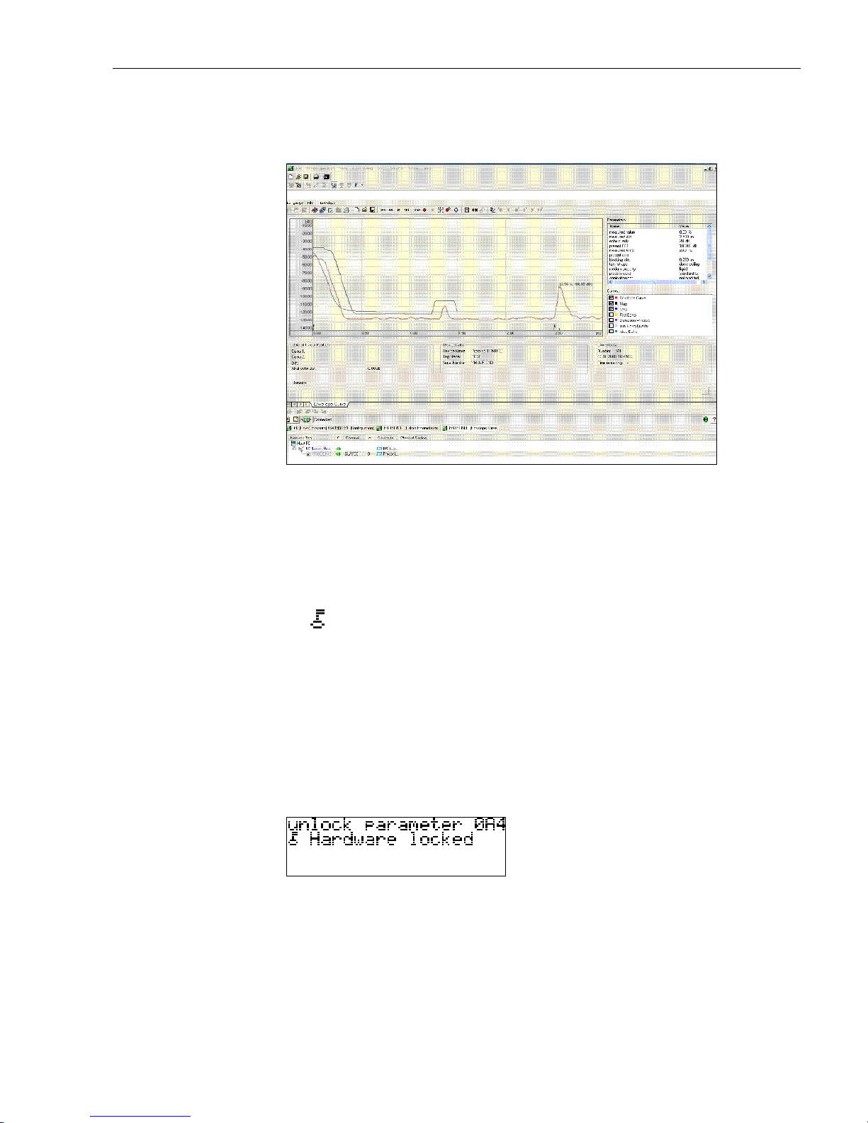
5.5.2 Envelope curve display
The FieldCare offers easy analysis of the envelope curve via the "Envelope" menu:
5.6 Lock/unlock configuration
5.6.1 Software security locking
Enter a number 100 in the "unlock parameter" (0A4) function in the "diagnostics" (0A)
function group.
The symbol appears on the display. Inputs are no longer possible.
If you try to change a parameter, the device jumps to the "unlock parameter" (0A4) function.
Enter "100"
Now change the parameters.
5.6.2 Hardware security locking
Press - and + and E simultaneously.
Inputs are no longer possible.
If you try to change a parameter, the following appears:
L00-fmrxf0a4-20-00-00-en-001
Press - and + and E simultaneously. The "unlock parameter" (0A4) function appears.
Enter "100"
Now change the parameters.
!
Note!
A hardware locking can only be unlocked again via the display by pressing the - and + and E keys
at the same time again. It is not possible to unlock the hardware by communication.
Page 26

Operation Prosonic T
26 Endress+Hauser
5.7 Resetting the customer parameters
It is advisable to reset the customer parameters if you want to use a device with an unknown history.
Effects of resetting:
• All customer parameters are reset to their default values.
• Customer interference echo suppression is not deleted.
• Linearisation is switched to "linear", but the table values are kept. The table can be switched
back on in the "linearisation" (04) function group in the "linearisation" (041) function.
In order to carry out the reset, enter the number "333" in the "reset" (0A3) function in the
"diagnostics" (0A) function group.
"
Caution!
A reset may lead to impairment of the measurement. As a rule, a basic calibration is required after
a reset.
!
Note!
The default values of each parameter are shown in bold in the menu overview in the appendix.
5.8 Resetting an interference echo suppression (tank map)
It is always advisable to reset the interference echo suppression (tank mapping) when:
• a device with an unknown history is used
• an incorrect suppression was input.
Proceed as follows:
1. Switch to the "extended calibr." (05) function group and to the "selection" (050)
function.
2. Select "extended map."
3. Then proceed to the "cust. tank map" (055) function.
4. Select
– "reset", to delete (reset) the existing interference echo suppression.
– "inactive" to deactivate an existing interference echo suppression. The suppression remains
saved.
– "active" to reactivate an existing interference echo suppression.
Page 27
Prosonic T Commissioning
Endress+Hauser 27
6 Commissioning
Commission the device in the following stages:
• Installation check
• Power-up device
• Basic calibration
• Measuring signal check using the envelope curve
The chapter describes the commissioning process using the on-site display. Commissioning using
FieldCare operating program is identical.
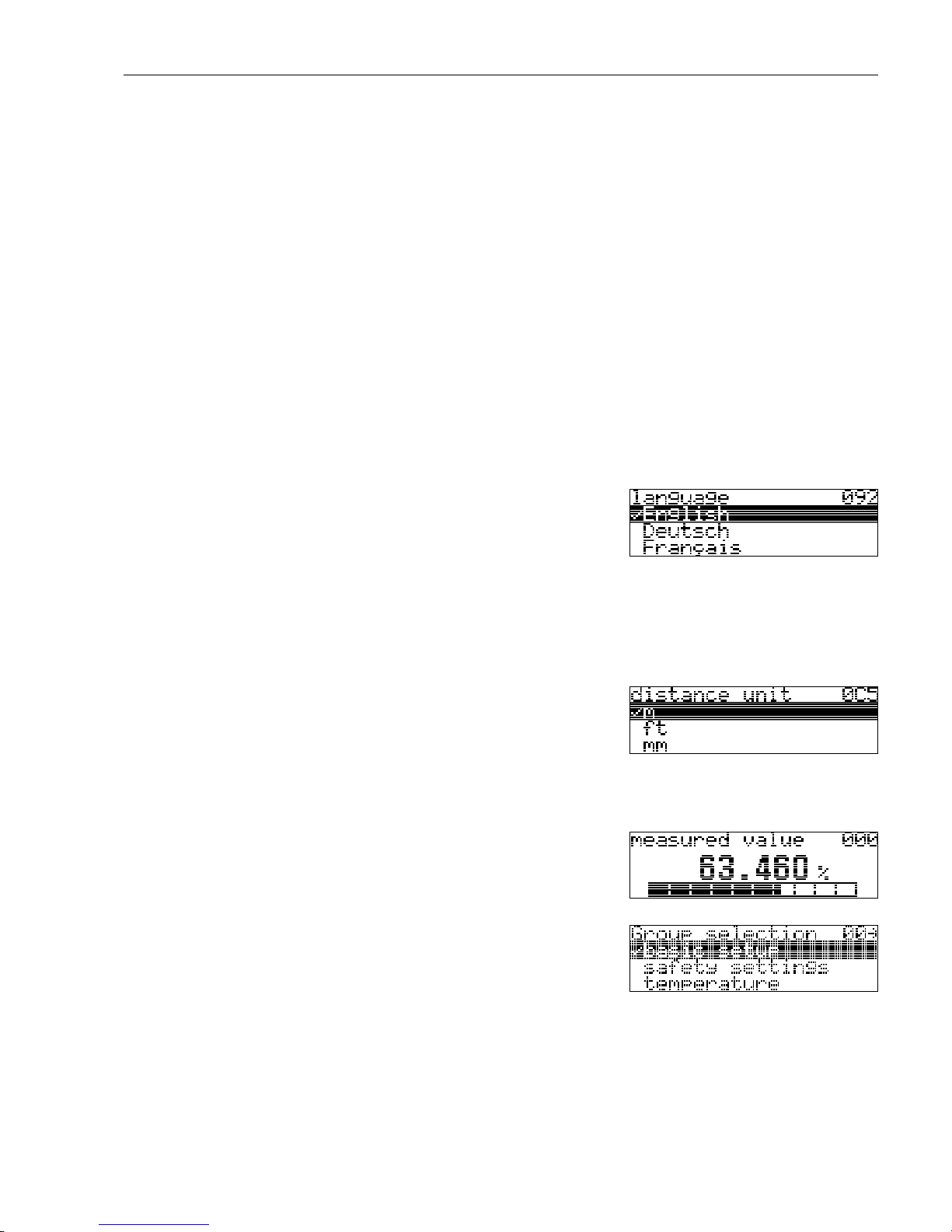
6.1 Power up instrument
After switching on the supply voltage, the instrument is first initialised.
Then the following appear for approximately five seconds:
• Device type
•Software version
Press E to exit this display.
On first power-up, you are requested to select
the language for the display texts. Available
language:
• English
•Deutsch
• Français
•Español
• Italiano
• Nederlands
• Japanese
L00-fmrxf092-20-00-00-en-001
Then you are requested to select the unit of
length for your measurements. Available unit of
length:
•m
•ft
•mm
•inch
L00-fmrxf0c5-20-00-00-en-001
A measured value is displayed. This is NOT
equivalent to the level in your tank. Firstly carry
out a basic calibration.
L00-fmrxf000-20-00-00-en-001
Press E to switch to the group selection.
Press E again to start the basic calibration.
L00-fmrxfg00-20-00-00-en-001
Page 28
Commissioning Prosonic T
28 Endress+Hauser
6.2 Basic calibration
The "Basic setup" (00) function group lists all the functions which are required for a standard
measurement task to commission the instrument. When you have completed your input for a
function, the next function appears automatically. In this way, you are guided through the complete
calibration.
6.2.1 Measuring point settings
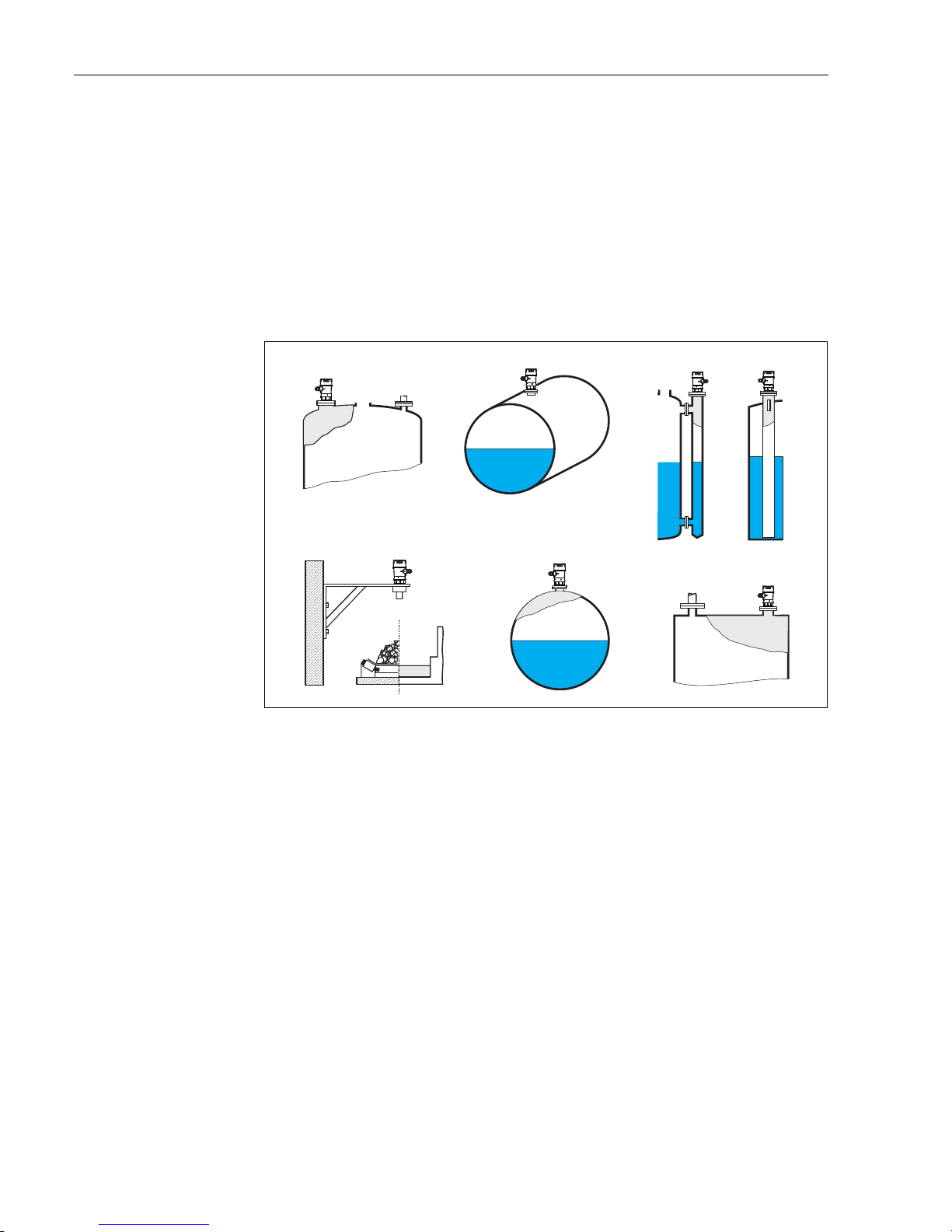
Function "tank shape" (002)
In this function, select one of the following options:
L00-FMU30xxx-14-00-06- xx-001
A dome ceiling
B horizontal cyl.
C bypass, stilling well/ultrasonic guide pipe
D no ceiling, e.g. dumps, open levels, chanels, weirs
E sphere
F flat ceiling
Function "medium property" (003)
Set the medium type in this function.
You have the following options:
• unknown (e.g. pasty media such as greases, creams, gels etc.)
• liquid
• solid, grain size < 4 mm, (fine)
• solid, grain size > 4 mm, (coarse)
A
BC
DE
F
Page 29
Prosonic T Commissioning
Endress+Hauser 29
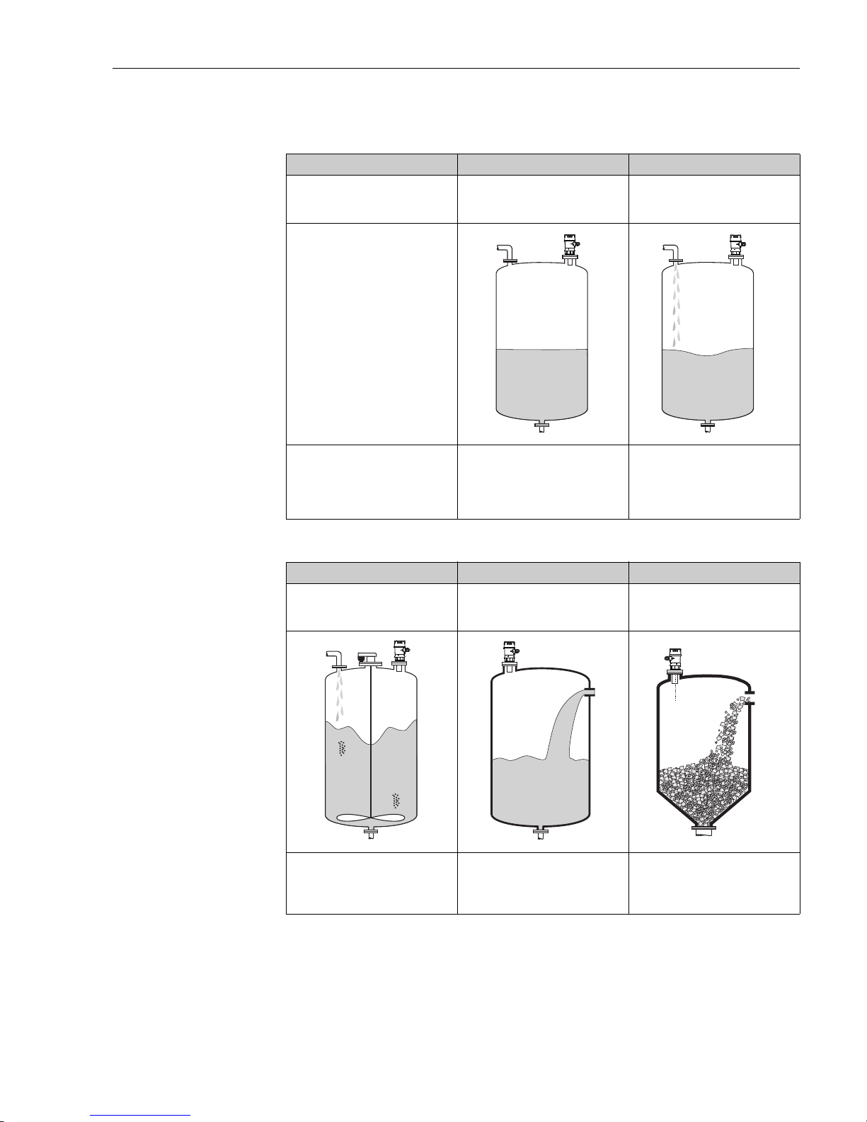
Function "process conditions" (004)
For this function, you have the following options:
standard liquids calm surface turb. surface
For all fluid applications which do not
fit in any of the following groups.
Storage tanks with immersion tube or
bottom filling
Storage / accumulation tanks with
uneven surface due to free filling,
mixing nozzles or small bottom stirrers
L00-FMU30xxx-14-00-00-xx-001 L00-FMU30xxx-14-00-00-xx-002
The filters and output damping are set
to average values.
The averaging filters and output
damping are set to large values.
-> Stable measured value
-> Accurate measurement
-> Slow reaction time
Special filters for stabilising the input
signal are activated.
-> Stable measured value
-> Medium reaction time
add. agitator fast change standard solid
Moving surfaces (poss. with vortex
formation) due to agitators
Rapid level change, particularly in
small tanks
For all bulk solids applications which
do not fit in any of the following
groups.
L00-FMU30xxx-14-00-00-xx-003 L00-FMU30xxx-14-00-00-xx-004 L00-FMU30xxx-14-00-00-xx-006
Special filters for stabilising the input
signal are set to large values.
-> Stable measured value
-> Medium reaction time
The averaging filters are set to small
values.
-> Rapid reaction time
-> Possibly unstable measured value
The filter and output damping are set
to average values.
Page 30
Commissioning Prosonic T
30 Endress+Hauser
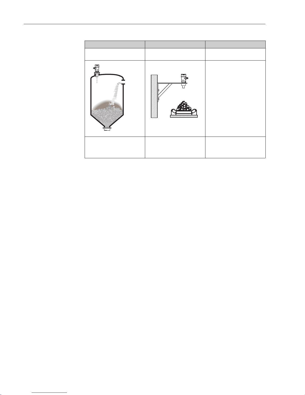
solid dusty conveyor belt Test: no filter
Dusty bulk solids Bulk solids with rapid level change All the filters can be switched off for
purposes of service and diagnosis.
L00-FMU30xxx-14-00-00-xx-007
L00-FMU30xxx-14-00-00-xx-005
The filters are set to detect even
relatively weak signals.
The averaging filters are set to small
values.
-> Rapid reaction time
-> Possibly unstable measured value
All filters off
Page 31
Prosonic T Commissioning
Endress+Hauser 31
6.2.2 Empty and full calibration
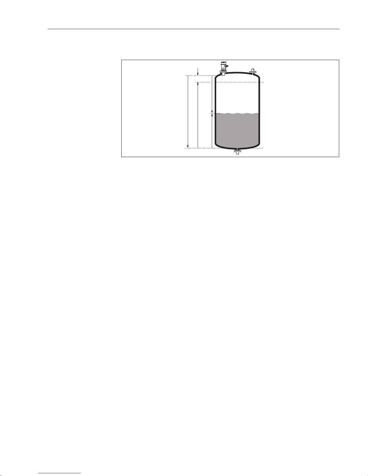
L00-FMU30-15-00-00-xx-001
BD Blocking distance D Distance from sensor membrane - product surface
E Empty distance F Span (full distance)
L Level
Function "empty calibration" (005)
In this function, enter the distance E from the sensor membrane to the minimum level (zero point).
"
Caution!
With dished boiler heads or conical outflows, the zero point should not be deeper than the point at
which the ultrasonic wave impinges on the tank bottom.
Function "blocking distance" (059)
In this function the blocking distance (BD) of the sensor is displayed.
"
Caution!
When entering the full calibration (span), please take into account, that the maximum level may not
project into the blocking distance (BD).
!
Note!
After basic calibration, enter a safety distance (SD) in the "safety distance" (015) function. If the
level is within this safety distance, the instrument signals a warning or an alarm, depending on your
selection in the "in safety distance" (016) function.
Function "full calibration" (006)
In this function, enter the span F, i.e. the distance from the minimum level to the maximum level.
20 mA
100%
4mA
0%
D
L
E
F
BD
Page 32
Commissioning Prosonic T
32 Endress+Hauser
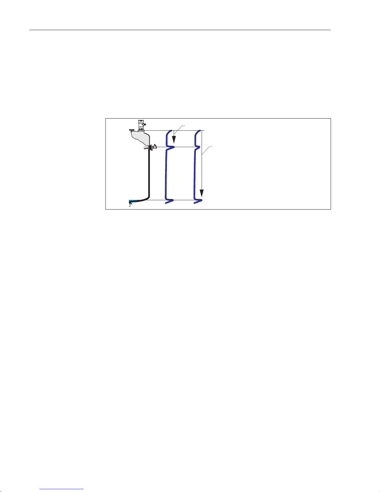
6.2.3 Interference echo suppression (tank mapping)
Function "dist./measured value" (008)
In the "dist./meas.value" (008) function, the measured distance D from the sensor membrane
to the product surface is displayed together with level L. Check these values.
Function "check distance" (051)
The mapping is initialized by this function.
L00-FMU3KAxxx-14-00-06-xx-010
1 Distance too small
2Distance = ok
Select
• "distance=ok" if the correct distance is displayed. Any echoes closer to the sensor will be
suppressed by the following interference echo suppression.
• "dist. too small" if the displayed distance is too small. In this case, the signal comes from an
interference echo which will be suppressed.
• "dist. too big" if the displayed distance is too large. This error cannot be cancelled by suppressing
the interference echo. This means that the following two functions are skipped. Check the
application parameters "tank shape" (002), "medium property" (003) and "process
cond." (004) and the "empty calibr."(005) in the "basic setup" (00) function group.
• "dist. unknown" if you do not know the actual distance. This means that the following two
functions are skipped.
• "manual" if you want to specify the suppression area yourself in the following function.
Function "range of mapping" (052)
The suggested suppression area is displayed in this function. The reference point is always the sensor
membrane. You can still edit the value. With manual suppression, the default value is 0 m.
"
Caution!
The suppression range must end 0.3 m (1 ft) in front of the echo of the actual level. With an empty
tank, do not enter E but E – 0.3 m.
+
+
1
2
Page 33

Prosonic T Commissioning
Endress+Hauser 33
Function "start mapping" (053)
You have the following options for this function:
• off: Nothing is suppressed.
• on: Starts suppression.
!
Note!
If a mapping already exists, it will be overwritten up to the distance specified in the "range of
mapping" (052) function. Beyond this distance the existing mapping remains unchanged.
Function dist./measured value (008)
After suppression, the measured distance D from the sensor membrane to the product surface is
displayed together with the level. Check that the values correspond to the actual level and/or the
actual distance.
The following cases may occur:
• Distance correct – Level correct -> End of basic calibration
• Distance incorrect – Level incorrect -> An additional interference echo suppression must be
carried out. Go back to the "check distance" (051) function.
• Distance correct – Level incorrect -> Check the value of the "empty calibr." (005) function.
Return to group selection
After the interference echo suppression the basic setting is finished and the instrument jumps
automatically back into the group selection.
6.3 Envelope curve
After the basic setup, an evaluation of the measurement with the aid of the envelope curve
("envelope curve" (0E) function group) is recommended.
6.3.1 Function "plot settings" (0E1)
In this function, select whether you want to display
• just the envelope curve
• The envelope curve and the echo evaluation line FAC
• The envelope curve and interference echo suppression (map)
!
Note!
The FAC and the interference echo suppression (map) are explained in BA00388F "Prosonic T Description of Instrument Functions"
6.3.2 Function "recording curve" (0E2)
In this function, specify whether you want to display
• an individual envelope curve
• The current envelope curve, with cyclical refreshment.
Page 34
Commissioning Prosonic T
34 Endress+Hauser
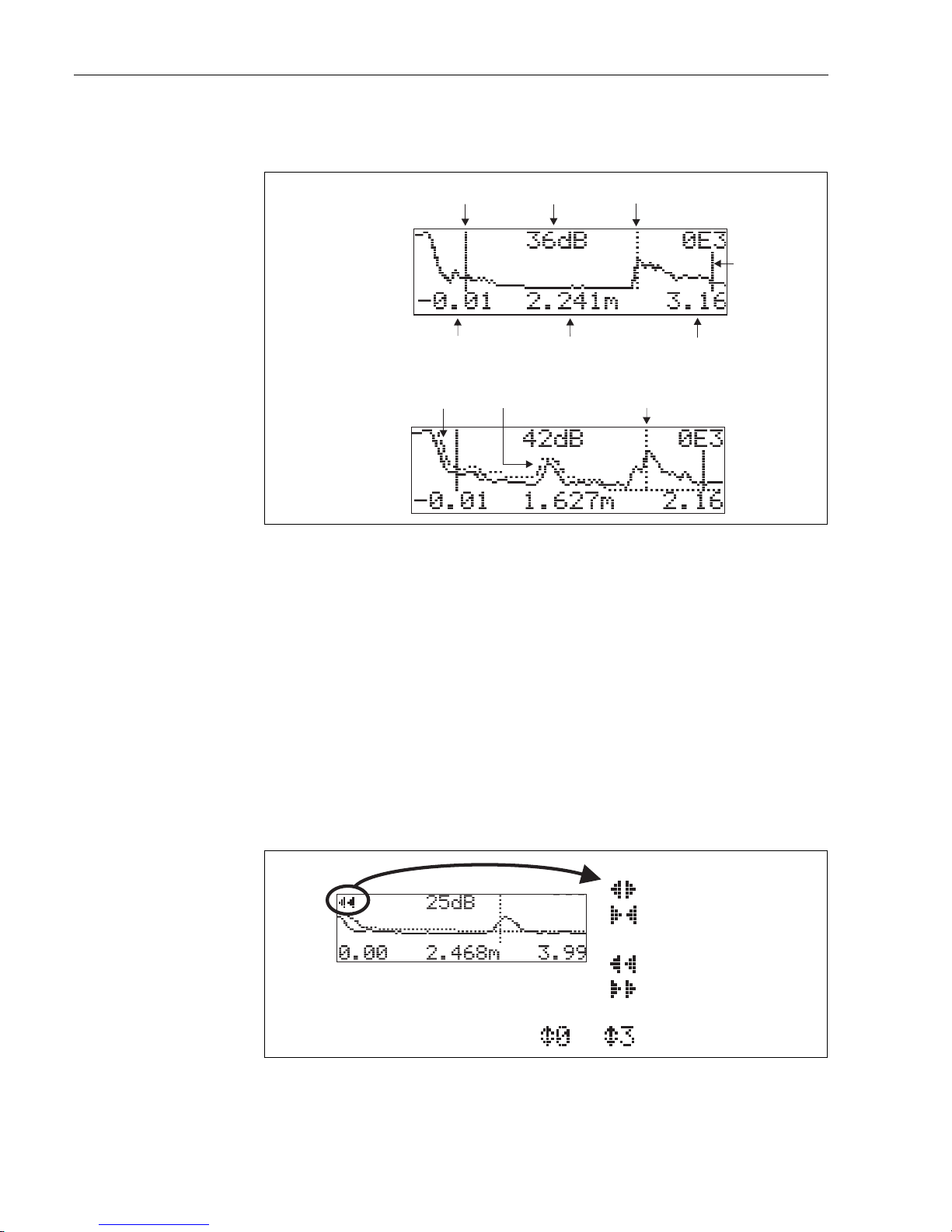
6.3.3 Function "envelope curve display" (0E3)
The envelope curve is displayed in this function. You can use it to obtain the following information:
L00-FMU4xxxx-07-00-00-en-003
Check that the following conditions are fulfilled:
• The echo quality at the end of measuring range should be at least 10 dB.
• There should be practically no interference echoes in front of the level signal.
• If interference echoes cannot be avoided, they must be below the suppression curve.
!
Note!
If the cyclical envelope curve display is still active on the display, the measured value is updated at
a slower cycle time. We therefore advise you to exit the envelope curve display after optimising the
measuring point. To do this, press E. (The instrument does not leave the envelope curve display
automatically.)
6.3.4 Navigation in the envelope curve display
Using navigation, the envelope curve can be scaled horizontally and vertically and shifted to the left
or the right. The active navigation mode is indicated by a symbol in the top left hand corner of the
display.
L00-FMxxxxxx-07-00-00-en-004
minimum distance
of the plot
maximum distance
of the plot
distance of
evaluated echo
interference echo
evaluated echo
is marked
quality of
evaluated echo
empty calibr.
envelope curve
only
envelope curve and
interference echo
suppression (map)
level echo
map
full calibr.
…
OE3
Move mode:
- m-oved to the left
moved to the right
Horizontal Zoom mode:
- h-orizontal zoom in
horizontal zoom out
Vertical Zoom mode:
- vertical zoom (4 steps)
Page 35
Prosonic T Commissioning
Endress+Hauser 35
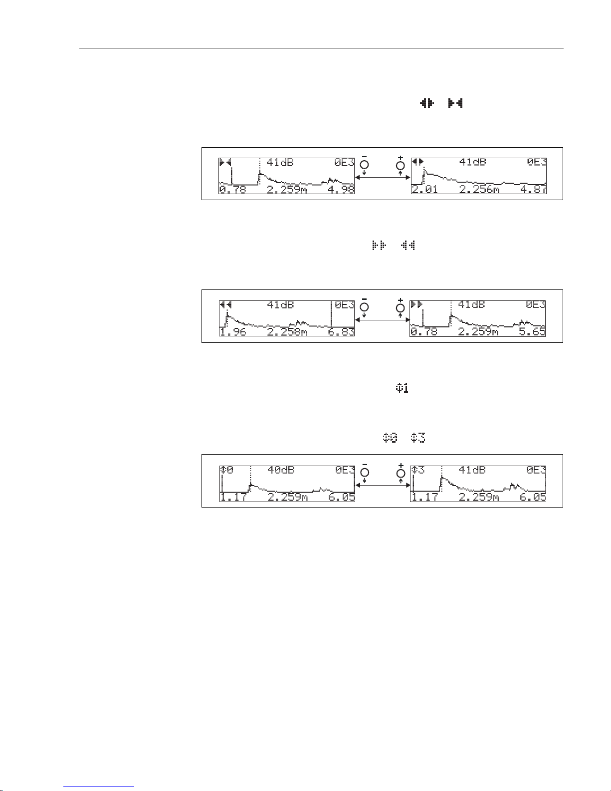
Horizontal Zoom mode
Firstly, go into the envelope curve display. Then press + or - to switch to the envelope curve
navigation. You are then in Horizontal Zoom mode. Either or is displayed.
• + increases the horizontal scale.
• - reduces the horizontal scale.
L00-FMU3xxxx-07-00-00-xx-007
Move mode
Then press E to switch to Move mode. Either or is displayed.
•+ shifts the curve to the right.
• - shifts the curve to the left.
L00-FMU3xxxx-07-00-00-xx-008
Vertical Zoom mode
Press E once more to switch to Vertical Zoom mode. is displayed. You now have the following
options.
• + increases the vertical scale.
• - reduces the vertical scale.
The display icon shows the current zoom factor ( to ).
L00-FMU3xxxx-07-00-00-xx-009
Exiting the navigation
• Press E again to run through the different modes of the envelope curve navigation.
• Press + and - to exit the navigation. The set increases and shifts are retained. Only when you
reactivate the "recording curve" (0E2) function the display settings return to their standard
values.
Page 36
Troubleshooting Prosonic T
36 Endress+Hauser
7Troubleshooting
7.1 System error messages
7.1.1 Current error
Errors which the instrument detects during commissioning or operation are displayed:
•In the "measured value" (000) function
•In the "diagnostics" (0A) function group in the "present error" (0A0) function
Only the highest priority error is displayed; in the case of multiple errors, you can scroll between
the different error messages by pressing + or -.
7.1.2 Last error
The last error is displayed in the "diagnostics" (0A) function group in the "previous error"
(0A1) function. This display can be deleted in the "clear last error" (0A2) function.
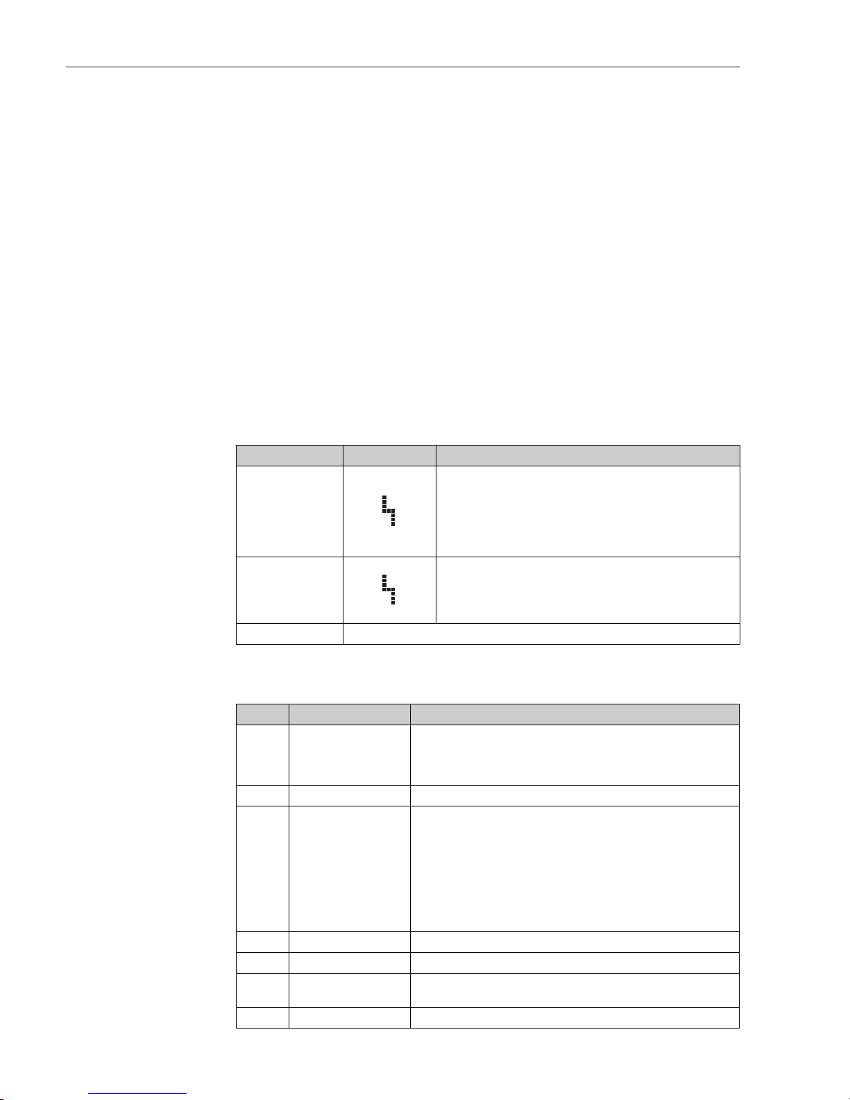
7.1.3 Types of error
7.1.4 Error codes
Type of error Symbol Meaning
Alarm (A)
continuous
The output signal assumes a value which can be set using the "output
on alarm" (010) function:
• MAX: 110 %, 22 mA
• MIN: -10 %, 3.8mA
• Hold: last value is on hold
• User-specific value
Warning (W)
flashing
The device continues measurement. An error message is displayed.
Alarm/Warning (E) You can define whether the error should behave as an alarm or as a warning.
Code Error description Action
A102
A110
A152
A160
checksum error Reset;
If alarm still present after reset, replace electronics
A106 downloading Wait; Message disappears after load sequence
A111
A113
A114
A115
A121
A125
A155
A164
A171
electronics defect Reset;
Check system for EMC, improve as necessary
If alarm still present after reset, replace electronics
A116 download error Check connection; Restart download
A231 sensor defect Check connection, if necessary replace HF module or electronics
A281 interruption temperature
sensor
Exchange sensor
A502 Sensor type not detected Exchange sensor and/or electronics
Page 37

Prosonic T Troubleshooting
Endress+Hauser 37
A521 new sensor type detected Reset
A661 Sensor overtemperature
A671 Linearisation incomplete Activate linearisation table
E641 no usable echo Check basic calibration
E651 level in safety distance -
risk of overspill
Error disappears when the level leaves the safety distance. Possibly reset the
lock. ["safety settings" (01) function group, "ackn. alarm" (017) function]]
W103 initialising If the message does not disappear after several seconds, replace the electronics
W153 initialising Wait a few seconds; if error is still displayed, switch the power off and on again
W512 recording of mapping Alarm disappears after a few seconds
W601 linearisation curve not
monotone
Correct table (enter monotonously increasing table)
W611 less than 2 linea-risation
points
Enter additional value pairs
W621 simulation on Switch simulation mode off ["output" (06) function group, "simulation"
(065) function]]
W681 current out of range (3.8 to
20.5 mA)
Carry out basic calibration;
check linearisation
W691 Filling noise detected, level ramp is active
Code Error description Action
Page 38
Troubleshooting Prosonic T
38 Endress+Hauser
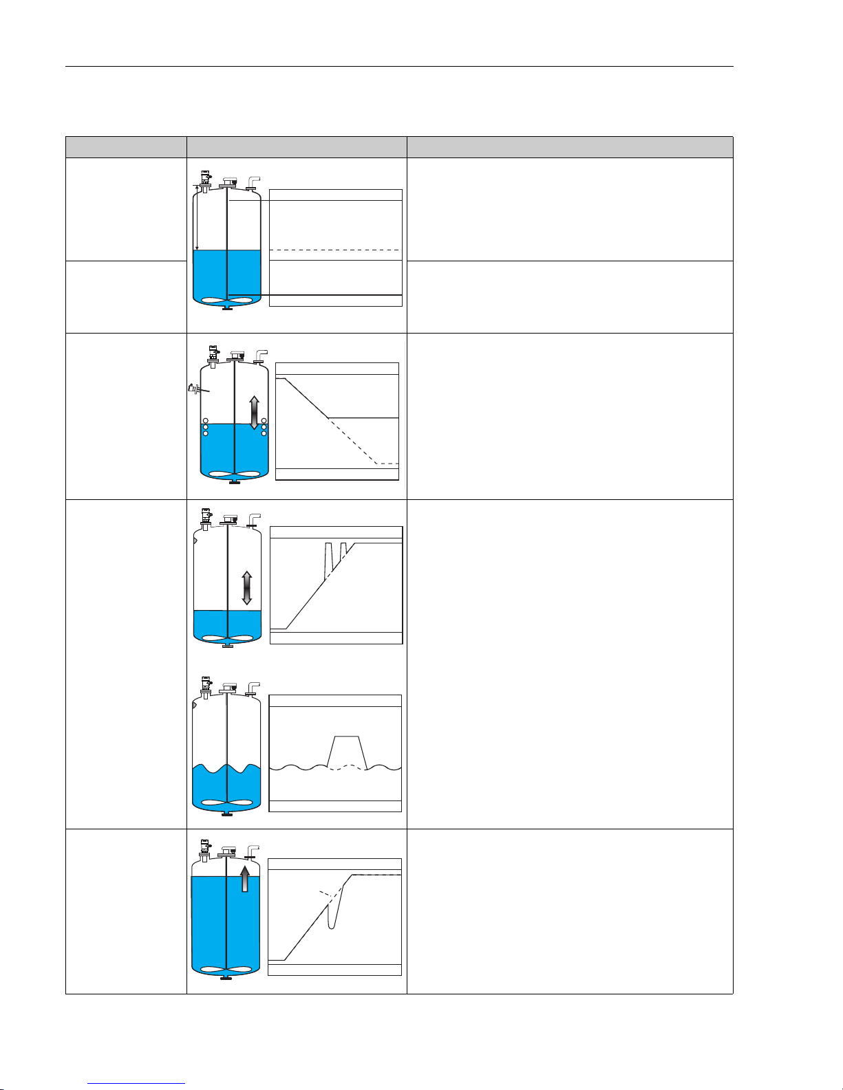
7.2 Application errors
Error Example Elimination
Measured value (00) is
incorrect but measured
distance (008) is correct
L00-FMU30xxx-19-00-00-en-019
1. Check empty calibration (005) and
full calibration (006).
2. Check linearisation
– level/ullage (040)
– max. scale(046)
– diameter vessel(047)
– linearisation table
Measured value (000) and
measured distance (008)
are incorrect
1. For measurements in bypass or stilling well:
Select the according option in the "tank shape" (002) function.
2. Carry out interference echo suppression.
No change in
measured value on filling/
emptying
L00-FMU30xxx-19-00-00-en-014
1. Carry out interference echo suppression.
2. Clean sensor if necessary
3. If necessary, select better installation position
4. If necessary due to wide interference echoes, set function "detection
window" (0A7) to "off".
With an uneven surface
(e.g. filling, emptying,
running agitator) the
measured value
may jump sporadically to
higher
levels
L00-FMU30xxx-19-00-00-en-015
L00-FMU30xxx-19-00-00-en-016
1. Carry out interference echo suppression
2. Set the process cond. (004) to "calm surface" or "add. agitator"
3. Increase output damping (058).
4. If necessary, select a different installation position and/or a larger sensor
On filling/emptying the
measured value drops
L00-FMU30xxx-19-00-00-en-017
1. Check tank shape (002), e.g. "dome ceiling" or "horizontal cyl."
2. If possible, do not select a central installation position
3. Possible user stilling well/echo guide pipe
100%
F m/ft
E m/ft
0% t
→
D m/ft (008)
actual
expected
100%
0% t
→
actual
expected
100%
0% t →
actual
expected
100%
0% t →
actual
expected
100%
0% t →
actual
expected
Page 39
Prosonic T Troubleshooting
Endress+Hauser 39
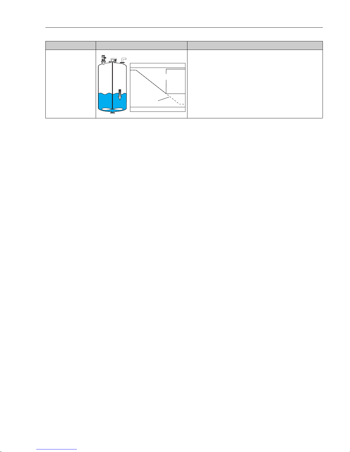
E 641 (echo loss)
L00-FMU30xxx-19-00-00-en-020
1. Check application parameters (002), (003) and (004)
2. If necessary, select a different installation position and/or a larger sensor
3. Align the sensor parallel to the product surface (particularly for bulk solids
applications)
Error Example Elimination
100%
E 641
0% t
actual
expected
Page 40

Maintenance and repairs Prosonic T
40 Endress+Hauser
8 Maintenance and repairs
8.1 Exterior cleaning
When cleaning the exterior, always use cleaning agents that do not attack the surface of the housing
and the seals.
8.2 Repairs
The Endress+Hauser repair concept assumes that the measuring devices have a modular design and
that customers are able to undertake repairs themselves ä 41, "Spare Parts". For more
information on service and spare parts, contact the Service Department at Endress+Hauser.
8.3 Repairs to Ex-approved devices
When carrying out repairs to Ex-approved devices, please note the following:
• Repairs to Ex-approved devices may only be carried out by trained personnel or by the
Endress+Hauser Service.
• Comply with the prevailing standards, national Ex-area regulations, safety instructions (XA) and
certificates.
• Only use original spare parts from Endress+Hauser.
• When ordering a spare part, please note the device designation on the nameplate. Only replace
parts with identical parts.
• Carry out repairs according to the instructions. On completion of repairs, carry our the specified
routine test on the device.
• Only Endress+Hauser Service may convert a certified device into a different certified variant.
• Document all repair work and conversions.
8.4 Replacement
After a complete instrument or electronic module has been replaced, the parameters can be
downloaded into the instrument again via the communication interface. Prerequisite to this is that
the data were uploaded to the PC beforehand using FieldCare. Measurement can continue without
having to carry out a new setup. Only a linearisation and a tank map (interference echo suppression)
have to be recorded again.
Page 41
Prosonic T Maintenance and repairs
Endress+Hauser 41
8.5 Spare Parts
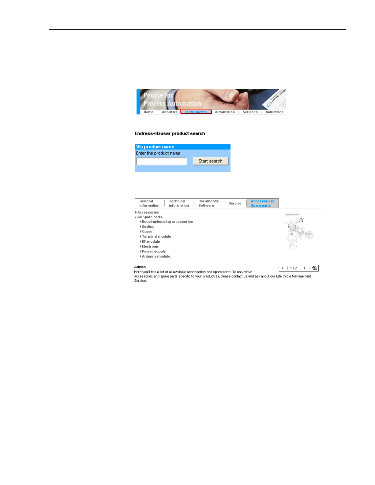
An overview of the spare parts for your device is available in the internet at www.endress.com.
To obtain information on the spare parts, proceed as follows:
1. Go to "www.endress.com" and select your country.
2. Click "Instruments".
3. Enter the product name into the "product name" field.
4. Select the device.
5. Click the "Accessories/Spare parts" tab.
6. Select the required spare parts (You may also use the overview drawing on the right side of the
screen.)
When ordering spare parts, always quote the serial number indicated on the nameplate. As far as
necessary, the spare parts also include replacement instructions.
Page 42

Maintenance and repairs Prosonic T
42 Endress+Hauser
8.6 Return
Returning devices
The measuring device must be returned if repairs or a factory calibration are required, or if the
wrong measuring device has been ordered or delivered. According to legal regulations,
Endress+Hauser, as an ISO-certified company, is required to follow certain procedures when
handling returned products that are in contact with medium.
To ensure swift, safe and professional device returns, please read the return procedures and
conditions on the Endress+Hauser website at www.services.endress.com/return-material
8.7 Disposal
In case of disposal please seperate the different components according to their material consistence.
8.8 Contact addresses of Endress+Hauser
Contact addresses can be found on our homepage: www.endress.com/worldwide. If you have any
questions, please do not hesitate to contact your Endress+Hauser representative.
Page 43
Prosonic T Accessories
Endress+Hauser 43
9 Accessories
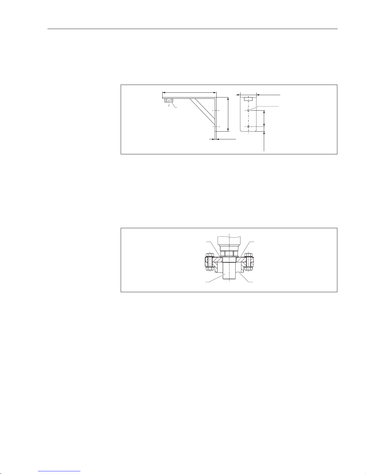
9.1 Installation bracket
A0019346
• G1½: Order No. 942669-0000
• G2: Order No. 942669-0001
suited for NPT 1½" and 2" as well
9.2 Screw in flange
A0019281
1 Screw in flange
2 Nozzle
3Sensor
4 Sealing ring EPDM (supplied)
400 (15.7)
120 (4.72)
120
(4.72)
30 (1.2)
250 (9.84)
G
ø16 (0.6)
3 (0.12)
mm (in)
4
1
3
2
Page 44
Accessories Prosonic T
44 Endress+Hauser
Screw in flange FAX50
The filled in options result in the complete order code.
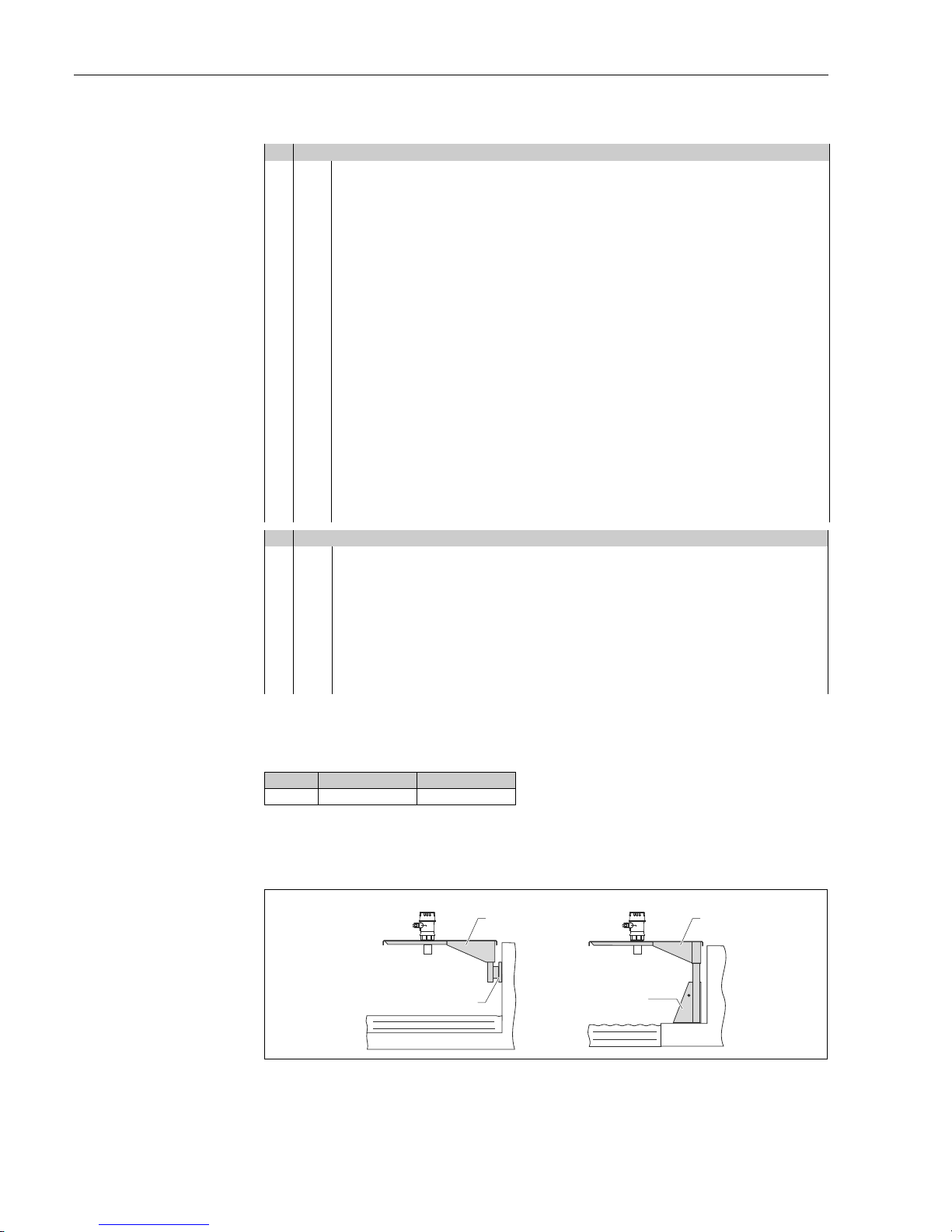
9.3 Cantilever with mounting frame or wall bracket
A0019566
A Installation with cantilever and wall bracket
B Installation with cantilever and mounting frame
1 Cantilever
2 Mounting frame
3 Wall bracket
015 Material:
BR1 DN50 PN10/16 A, steel flange EN1092-1
BS1 DN80 PN10/16 A, steel flange EN1092-1
BT1 DN100 PN10/16 A, steel flange EN1092-1
JF1 2" 150lbs FF, steel flange ANSI B16.5
JG1 3" 150lbs FF, steel flange ANSI B16.5
JH1 4" 150lbs FF, steel flange ANSI B16.5
JK2 8" 150lbs FF, PP max 3bar abs/44psia flange ANSI B16.5
XIF UNI flange 2"/DN50/50, PVDF max 4bar abs/58psia, suitable for 2" 150lbs/DN50 PN16/10K 50
XIG UNI flange 2"/DN50/50, PP max 4bar abs/58psia, suitable for 2" 150lbs/DN50 PN16/10K 50
XIJ UNI flange 2"/DN50/50, 316L max 4bar abs/58psia, suitable for 2" 150lbs/DN50 PN16/10K 50
XJF UNI flange 3"/DN80/80, PVDF max 4bar abs/58psia, suitable for 3" 150lbs/DN80 PN16/10K 80
XJG UNI flange 3"/DN80/80, PP max 4bar abs/58psia, suitable for 3" 150lbs/DN80 PN16/10K 80
XJJ UNI flange 3"/DN80/80, 316L max 4bar abs/58psia, suitable for 3" 150lbs/DN80 PN16/10K 80
XKF UNI flange 4"/DN100/100, PVDF max 4bar abs/58psia, suitable for 4" 150lbs/DN100 PN16/10K 100
XKG UNI flange 4"/DN100/100, PP max 4bar abs/58psia, suitable for 4" 150lbs/DN100 PN16/10K 100
XKJ UNI flange 4"/DN100/100, 316L max 4bar abs/58psia, suitable for 4" 150lbs/DN100 PN16/10K 100
XLF UNI flange 6"/DN150/150, PVDF max 4bar abs/58psia, suitable for 6" 150lbs/DN150 PN16/10K 150
XLG UNI flange 6"/DN150/150, PP max 4bar abs/58psia, suitable for 6" 150lbs/DN150 PN16/10K 150
XLJ UNI flange 6"/DN150/150, 316L max 4bar abs/58psia, suitable for 6" 150lbs/DN150 PN16/10K 150
XMG UNI flange DN200/200, PP max 4bar abs/58psia, suitable for DN200 PN16/10K 200
XNG UNI flange DN250/250, PP max 4bar abs/58psia, suitable for DN250 PN16/10K 250
YYY Special version
020 Sensor Connection:
A Thread ISO228 G3/4
B Thread ISO228 G1
C Thread ISO228 G1-1/2
D Thread ISO228 G2
EThread ANSI NPT3/4
FThread ANSI NPT1
GThread ANSI NPT1-1/2
HThread ANSI NPT2
Y Special version
015 020
FAX50 -
3
1
2
AB
1
Page 45
Prosonic T Accessories
Endress+Hauser 45
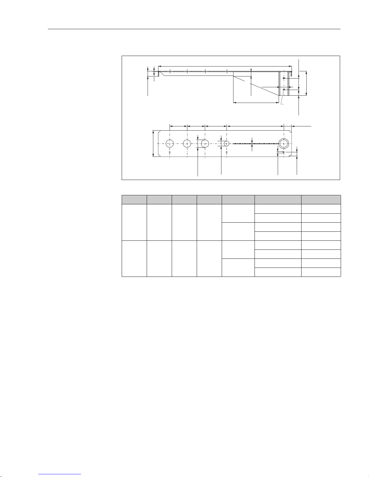
Cantilever
A0019349
• The 50 mm (2.17 in) or 62 mm (2.44 in) orifices serve for the mounting of the 1½" or 2" sensor,
respecitvely.
• The 22 mm (0.87 in) orifice may be used for an additional sensor.
For the mounting of the cantilever can be used:
• mounting frame ä 46
• wall bracket ä 46
A B C D for Sensor Material Order Code
585 (23) 250 (9.84) 2 (0.08) 200 (7.87) 1½" 316Ti (1.4571) 52014132
galv. steel 52014131
2" 316Ti (1.4571) 52014136
galv. steel 52014135
1085 (42.7) 750 (29.5) 3 (0.12) 300 (11.8) 1½" 316Ti (1.4571) 52014134
galv. steel 52014133
2" 316Ti (1.4571) 52014138
galv. steel 52014137
mm (in)
A
D
M8
35 (1.4)
50 (2.0)
20 (0.8)
105 (4.1)
50/62
(2.0/2.4)
22 (0.9)
C
C
6.5 (0.3)
15 (0.6)
100 (3.9)
25 (1.0)
35 (1.4)
100 (3.9)75 (2.9)
B
20 (0.8)
75 (2.9)
mm (in)
Page 46
Accessories Prosonic T
46 Endress+Hauser
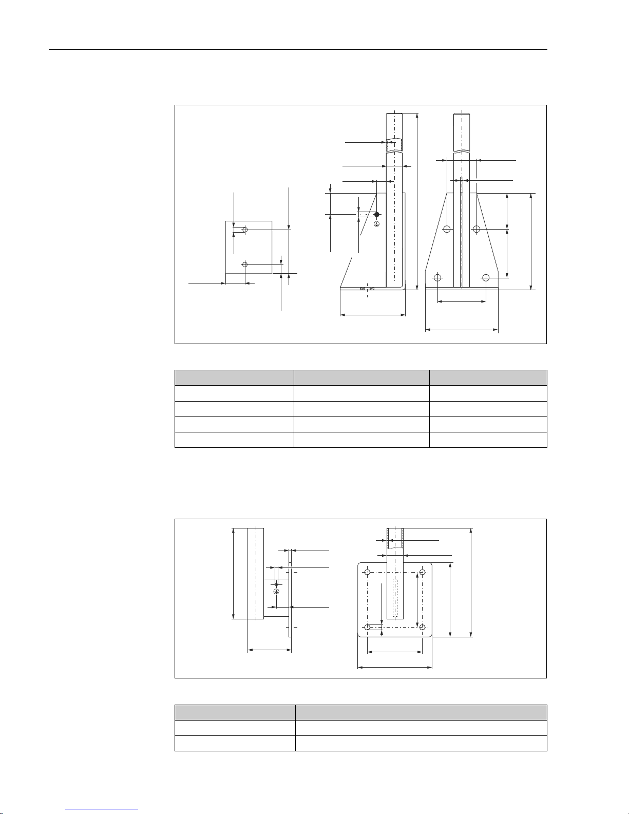
9.4 Mounting Frame
A0019279
9.5 Wall Bracket
A0019350
Height Material Order Code
700 (27.6) galv. steel 919791-0000
700 (27.6) 316Ti (1.4571) 919791-0001
1400 (55.1) galv. steel 919791-0002
1400 (55.1) 316Ti (1.4571) 919791-0003
mm (in)
Material Order Code
galv. steel 919792-0000
316Ti (1.4571) 919792-0001
3.2 (0.13)
20 (0.8)
55 (2.17)
100 (3.94)
25 (0.98)
700/1400
(27.6 / 55.1)
45 (1.77)
76
(2.99)
100
(3.94)
200 (7.87)
13 (0.5)
ø33.7 (1.3)
130 (5.12)
150 (5.91)
100
(3.94)
60 (2.36)
4 (0.16)
6.5 (0.3)
mm (in)
110 (4.3)
25 (1.0)
5 (0.2)
6.5 (0.3)
150 (5.9)
ø33.7 (1.3)
3.2 (0.1)
110 (4.3)
13 (0.5)
150 (5.9)
180 (7.1)
~213 (8.4)
~ (3.5)88
mm (in)
Page 47

Prosonic T Accessories
Endress+Hauser 47
9.6 Commubox FXA291
The Commubox FXA291 connects Endress+Hauser field instruments with CDI interface (=
Endress+Hauser Common Data Interface) to the USB interface of a personal computer or a
notebook. For details refer to TI00405C/07/EN.
Note!
For the FMU30 you need the "ToF Adapter FXA291" as an additional accessory.
9.7 ToF Adapter FXA291
The ToF Adapter FXA291 connects the Commubox FXA291 via the USB interface of a personal
computer or a notebook to the FMU30.
For details refer to KA00271F/00/A2.
Page 48
Technical Data Prosonic T
48 Endress+Hauser
10 Technical Data
10.1 Technical data at a glance
10.1.1 Input
Measured variable The distance D between the sensor membrane and the product surface is measured.
Using the linearisation function, the device uses D to calculate:
• level L in any units
• volume V in any units
• flow Q across measuring weirs or open channels in any units
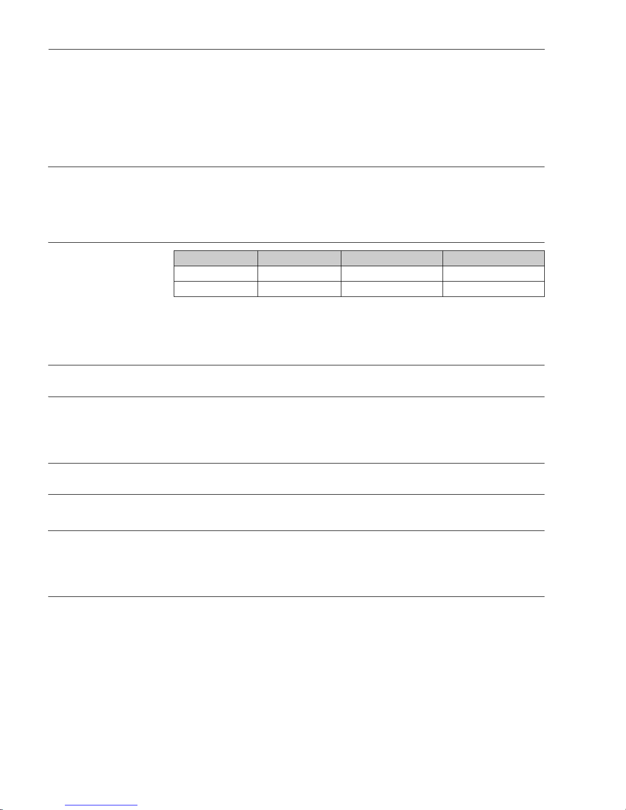
Maximum range/blocking
distance
10.1.2 Output
Output signal 4 to 20 mA
Signal on alarm • Error symbol, error code and plain text description on the on-site display
• Current output (configurable)
10.1.3 Power supply
Terminals Cable cross-section: 0.25 to 2.5 mm (20 to 14 AWG)
Cable entry • Cable gland M20x1.5 (recommended cable diameter 6 to 10 mm (0.24 to 0.39 in))
• Cable entry G½ or ½ NPT
Supply voltage 14 to 35 V
There may be additional restrictions for devices with an explosion protection certificate. Refer to the
notes in the appropriate safety instructions (XA).
Power consumption 51 mW to 800 mW
Sensor BD Max. range fluids
1)
1) The actual range is dependent on the measuring conditions. Refer to Technical Information TI00440F/00/EN for
an estimation.
Max. range bulk materials
1½" 0.25 m (0.8 ft) 5 m (16 ft) 2 m (6.6 ft)
2" 0.35 m (1.1 ft) 8 m (26 ft) 3.5 m (11 ft)
Page 49

Prosonic T Technical Data
Endress+Hauser 49
10.1.4 Performance characteristics
Reaction time The reaction time depends on the parameter settings. The minimum value is: min. 2 s
Reference operating
conditions
• Temperature = +20 °C (68 °F)
• Pressure = 1013 mbar abs. (15 psi abs.)
• Humidity = 50 %
• Ideal reflective surface (e.g. calm, smooth fluid surface)
• No interference reflections within signal beam
• Set application parameters:
– Tank shape = flat ceiling
– Medium property = liquid
– process conditions = calm surface
Measured value resolution 1 mm (0.04 in)
Measuring error Typical specifications for reference operating conditions (include linearity, repeatability, and
hysteresis):
±3mm (±0.12 in) or 0.2 % of set measuring distance (empty calibration)
1
1
whichever is greater
Influence of the vapor pressure The vapor pressure at 20 °C (68 °F) gives a hint on the accuracy of the ultrasonic level
measurement. If the vapor pressure at 20 °C (68 °F) is below 50 mbar (0.73 psi), ultrasonic level
measurement is possible with a very high accuracy. This is valid for water, aqueous solutions, watersolid-solutions, dilute acids (hydrochloric acid, sulfuric acid, ...), dilute bases (caustic soda, ...), oils,
greases, slurries, pastes, ...
High vapor pressures or outgassing media (ethanol, acetone, ammonia, ...) can influence the
accuracy. If conditions like these are present, please contact the Endress+Hauser support.
Page 50

Technical Data Prosonic T
50 Endress+Hauser
10.1.5 Environment
Ambient temperature -20 °C to + 60 °C (-4 °F to +140 °F)
Use a protective cover, in order to protect the sensor from direct sun or rain, see the Technical
Documentation TI00440F/00/EN.
Storage temperature -40 °C to +80 °C (-40 °F to +176 °F)
Climate class DIN EN 60068-2-38 (Test Z/AD) DIN/IEC 68 T2-30Db
Ingress protection • With closed housing, tested according to
– IP 68 (24h at 1.83m (6.0 ft) under water surface)
– IP 66
• With open housing: IP 20 (also ingress protection of the display)
Vibration resistance DIN EN 60068-2-64 / IEC 68-2-64: 20…2000 Hz, 1 (m/s
)2
/Hz; 3 x 100 min
Electromagnetic compatibility
(EMC)
• Electromagnetic compatibility to EN 61326. For details refer to the declaration of conformity.
• With regard to interference immunity the requirements for "industrial environment" are met.
• Influence of EMC < 1 % FS
10.1.6 Process
Process temperature -20 °C to +60° C (-4 °F to +140 °F)
A temperature sensor is integrated in the sensor for correction of the temperature-dependent timeof-flight.
Process pressure 0.7 bar to 3bar abs. (10.15 psi to 43.5 psi)
Page 51

Prosonic T Technical Data
Endress+Hauser 51
Page 52
Appendix Prosonic T
52 Endress+Hauser
11 Appendix
11.1 Operating menu
L00-FMU3xxxx-19-00-00-en-005
safety settings
basic setup
output on alarm
MAX 110% 22 mA
hold
MIN - 10% 3,6 mA
userspecific
tank shape
dome ceiling
horizontal cyl.
bypass
stilling well
flat ceiling
sphere
no ceiling
measured temp.
is displayed
level/ullage
level DU
ullage DU
level CU
ullage CU
selction
mapping
common
extended map.
plot settings
envelope curve
env.curve + FAC
env.curve + cust.map
present error
tag no.
output on alarm
specify value specify value
medium property
solid < 4mm
solid > 4mm
unknown
liquid
max. temp. limit
is displayed
linearisation
table on
manual
semi-automatic
horizontal cyl.
linear
recording curve
single curve
cyclic
language
previous error
outp.echo loss
hold
alarm
ramp %/min
process cond.
standard liquid
calm surface
turb.surface
add. agitator
fast change
standard solid
solid dusty
conveyor belt
test: no filter
max. meas. temp.
is displayed
customer unit
TabNo
Level
volum
customer unit
customer unit
low output limit
on
off
back to home
specify time
Default: 100 s
clear last error
keep
erase
protocol + sw-no.
Rampe %span/min
empty calibr.
distance membrane
to min. level
Default:
FMU30: 5 m
FMU30: 8 m
react. high temp
warning
alarm
linearisation
pres.map dist.
is displayed
curr.output mode
curr.turn down
standard
fixed current
format display
decimal
1/16”
reset
for reset code
see manual
Note! The Default values of the parameters are typed in bold face.
delay time
in case of echo loss
max. 4000 sec.
Default: 60 s
full calibr.
span
max.: empty - BD
Default:
FMU30: 4,75 m
FMU30: 7,6 m
defect temp.sens.
alarm
warning
next point
yes
no
cust. tank map
inactive
active
reset
4 mA value
specify value
no.of decimalas
x
x.x
x.xxx
x.xx
unlock parameter
for unlock code
see manual
serial no.
temperature
linearisation
extended calibr.
output
envelope curve
display
diagnostics
system parameters
01
00
010
002
030
040
040
040
050
0E1
0A0
0C0
011
003
031
041
0E2
092
0A1
012
004
032
042
043
044
045
042
042
062
093
0A2
0C2
013
005
033
054
063
094
0A3
014
006
034
045
055
068
095
0A4
0C4
03
04
05
06
0E
09
0A
0C
clear table
dist./meas.value
the following are
displayed:
- distance membrane
to level
- measured value
check distance
manual
distance = ok
distance too small
distance too big
dist. unknown
range of mapping.
accept proposed value
or
specify range of
mapping
start mapping
off
on
008 051 052 053
Page 53
Prosonic T Appendix
Endress+Hauser 53
L00-FMU4xxxx-19-00-02-en-005
simulation
sim. off
sim. level
sim. volume
sim. current
sep.character
fixed cur.value
. period
, comma
measured dist.
distance unit
max. scale
max. scale
safety distance
from blocking distance
Default: 0,1m
dist./meas.value
the following are
displayed:
- distance membrane
to level
- measured value
echo quality
is displayed
simulation value
display test
off
on
measured level
temperature unit
diameter vessel
in safety dist.
warning
self holding
alarm
check distance
manual
distance = ok
distance too small
distance too big
dist. unknown
offset
will be added to the
measured level
output current
ackn.alarm
no
yes
range of mapping.
accept proposed value
or
specify range of
mapping
output damping
Default: 2 s
application par.
Return to Group selection
not modified
modified
download mode
parameter only
param.+ cust. map
mapping only
start mapping
off
on
20 mA value
specify value
blocking dist.
is displayed
dist./meas.value
the following are
displayed:
- distance membrane
to level
- measured value
065
096
064
0A5
0C5
046
046
015
008
056
066
097
0A6
0C6
047
016
051
057
067
017
052
058
0A8
0C8
053
069
059
008
dist./meas.value
the following are
displayed:
- distance membrane
to level
- measured value
008
detection window
off
on
reset
0A7
Page 54
Appendix Prosonic T
54 Endress+Hauser
11.2 Measuring principle
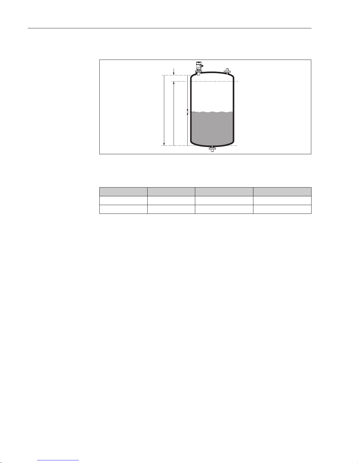
L00-FMU30-15-00-00-xx-001
BD Blocking distance D Distance from sensor membrane - product surface
E Empty distance F Span (full distance)
L Level
11.2.1 Time-of-flight method
The sensor of the instrument transmits ultrasonic pulses in the direction of the product surface.
There, they are reflected back and received by the sensor. The instrument measures the time t
between pulse transmission and reception. The instrument uses the time t (and the velocity of sound
c) to calculate the distance D between the sensor membrane and the product surface:
D = c t/2
As the device knows the empty distance E from a user entry, it can calculate the level as follows:
L = E - D
An integrated temperature sensor compensates for changes in the velocity of sound caused by
temperature changes.
11.2.2 Interference echo suppression
The interference echo suppression feature on the instrument ensures that interference echos (e.g.
from edges, welded joints and installations) are not interpreted as a level echo.
11.2.3 Calibration
Enter the empty distance E and the span F to calibrate the device.
11.2.4 Blocking distance
Span F may not extend into the blocking distance BD. Level echos within the blocking distance
cannot be evaluated due to the transient characteristics of the sensor.
20 mA
100%
4mA
0%
D
L
E
F
BD
Sensor BD Max. range fluids Max. range bulk materials
1½" 0.25 m (0.8 ft) 5 m (16 ft) 2 m (6.6 ft)
2" 0.35 m (1.1 ft) 8 m (26 ft) 3.5 m (11 ft)
Page 55

Prosonic T Index
Endress+Hauser 55
Index
A
alarm . . . . . . . . . . . . . . . . . . . . . . . . . . . . . . . . . . . . . . . . 36
application errors. . . . . . . . . . . . . . . . . . . . . . . . . . . . . . . . 38
B
blocking distance. . . . . . . . . . . . . . . . . . . . . . . . . . . . . 14, 31
C
cantilever . . . . . . . . . . . . . . . . . . . . . . . . . . . . . . . . . . . . . 44
CE mark . . . . . . . . . . . . . . . . . . . . . . . . . . . . . . . . . . . . . . . 8
cleaning . . . . . . . . . . . . . . . . . . . . . . . . . . . . . . . . . . . . . . 40
connection . . . . . . . . . . . . . . . . . . . . . . . . . . . . . . . . . . . . 16
D
declaration of conformity. . . . . . . . . . . . . . . . . . . . . . . . . . . 8
display appearance . . . . . . . . . . . . . . . . . . . . . . . . . . . . . . 20
display symbols . . . . . . . . . . . . . . . . . . . . . . . . . . . . . . . . . 20
E
error codes . . . . . . . . . . . . . . . . . . . . . . . . . . . . . . . . . . . . 36
error messages . . . . . . . . . . . . . . . . . . . . . . . . . . . . . . . . . 36
F
FieldCare . . . . . . . . . . . . . . . . . . . . . . . . . . . . . . . . . . . . . 24
flow measurements . . . . . . . . . . . . . . . . . . . . . . . . . . . . . . 12
full calibration . . . . . . . . . . . . . . . . . . . . . . . . . . . . . . . . . . 31
H
hardware security locking . . . . . . . . . . . . . . . . . . . . . . . . . 25
I
installation bracket . . . . . . . . . . . . . . . . . . . . . . . . . . . . . . 43
interference echo suppression . . . . . . . . . . . . . . . . . . . . . . 32
K
key assignment . . . . . . . . . . . . . . . . . . . . . . . . . . . . . . . . . 21
Khafagi-Venturi flume . . . . . . . . . . . . . . . . . . . . . . . . . . . . 12
L
level measurements. . . . . . . . . . . . . . . . . . . . . . . . . . . . . . 11
M
measuring principle . . . . . . . . . . . . . . . . . . . . . . . . . . . . . . 54
Measuring range . . . . . . . . . . . . . . . . . . . . . . . . . . . . . . . . 14
N
nozzle. . . . . . . . . . . . . . . . . . . . . . . . . . . . . . . . . . . . . . . . 14
O
on-site display . . . . . . . . . . . . . . . . . . . . . . . . . . . . . . . . . . 23
operating menu . . . . . . . . . . . . . . . . . . . . . . . . . . . . . . . . . 52
Operational safety . . . . . . . . . . . . . . . . . . . . . . . . . . . . . . . . 4
P
process conditions . . . . . . . . . . . . . . . . . . . . . . . . . . . . . . . 29
R
range . . . . . . . . . . . . . . . . . . . . . . . . . . . . . . . . . . . . . . . . 15
repairs to Ex-approved devices . . . . . . . . . . . . . . . . . . . . . . 40
return . . . . . . . . . . . . . . . . . . . . . . . . . . . . . . . . . . . . . . . . 42
S
Service-Interface FXA291 . . . . . . . . . . . . . . . . . . . . . . . . . 47
shafts. . . . . . . . . . . . . . . . . . . . . . . . . . . . . . . . . . . . . . . . . 12
software security locking . . . . . . . . . . . . . . . . . . . . . . . . . . 25
Spare Parts . . . . . . . . . . . . . . . . . . . . . . . . . . . . . . . . . . . . 41
W
warning. . . . . . . . . . . . . . . . . . . . . . . . . . . . . . . . . . . . . . . 36
Page 56

www.endress.com/worldwide
BA00387F/00/EN/14.14
71244271
SGML+FM10
71244271
 Loading...