

Page 1
Technical Information
Proline Prosonic Flow 91W
Ultrasonic Flow Measuring System
Flowrate measurement for standard applications with
drinking water and process water
Applications
The sensors are perfectly suited for the non-contact
measurement of pure or slightly contaminated liquids,
regardless of the pressure or electrical conductivity.
• Suitable for pipe diameters in the range
DN 15 to 2000 (½" to 80")
• Can be used with all metal and plastic pipes lined or
unlined
• Ideal solution for applications with water, e.g. drinking
water, industrial water, saltwater, deionized water,
cooling water and heating water
• Perfectly suitable for
– subsequent mounting
– flow monitoring
– improving measuring points
Features and benefits
The Prosonic Flow ultrasonic clamp-on system allows
accurate and cost-effective flow measurement from
outside the pipe and without the need to interrupt the
process. The flow measurement is bidirectional and
causes no pressure loss.
• Easy, safe and menu-guided sensor mounting ensures
precise measuring results
• Long-term system integrity thanks to robust sensor
and industrial mounting kit design
• Automatic frequency scan for optimized installation
and maximum measuring performance
• IP 68 for pipes under water
• Remote configuration using Endress+Hauser's
FieldCare software
TI00105D/06/EN/13.11
71136725
Page 2

Table of contents
Proline Prosonic Flow 91W
Function and system design. . . . . . . . . . . . . . . . . . . . . 3
Measuring principle . . . . . . . . . . . . . . . . . . . . . . . . . . . . . . . . . . . 3
Measuring . . . . . . . . . . . . . . . . . . . . . . . . . . . . . . . . . . . . . . . . . . 4
Sensor selection and arrangement . . . . . . . . . . . . . . . . . . . . . . . . . 5
Input . . . . . . . . . . . . . . . . . . . . . . . . . . . . . . . . . . . . . . 6
Measured variable . . . . . . . . . . . . . . . . . . . . . . . . . . . . . . . . . . . . 6
Measuring range . . . . . . . . . . . . . . . . . . . . . . . . . . . . . . . . . . . . . . 6
Operable flow range . . . . . . . . . . . . . . . . . . . . . . . . . . . . . . . . . . . 6
Output . . . . . . . . . . . . . . . . . . . . . . . . . . . . . . . . . . . . . 6
Output signal . . . . . . . . . . . . . . . . . . . . . . . . . . . . . . . . . . . . . . . . 6
Signal on alarm . . . . . . . . . . . . . . . . . . . . . . . . . . . . . . . . . . . . . . 6
Load . . . . . . . . . . . . . . . . . . . . . . . . . . . . . . . . . . . . . . . . . . . . . . 6
Low flow cutoff . . . . . . . . . . . . . . . . . . . . . . . . . . . . . . . . . . . . . . 6
Galvanic isolation . . . . . . . . . . . . . . . . . . . . . . . . . . . . . . . . . . . . . 6
Power supply . . . . . . . . . . . . . . . . . . . . . . . . . . . . . . . . 7
Measuring unit electrical connection . . . . . . . . . . . . . . . . . . . . . . . 7
Connecting the connecting cable . . . . . . . . . . . . . . . . . . . . . . . . . 8
Supply voltage . . . . . . . . . . . . . . . . . . . . . . . . . . . . . . . . . . . . . . . 8
Cable entry . . . . . . . . . . . . . . . . . . . . . . . . . . . . . . . . . . . . . . . . . 8
Cable-specification . . . . . . . . . . . . . . . . . . . . . . . . . . . . . . . . . . . . 9
power consumption . . . . . . . . . . . . . . . . . . . . . . . . . . . . . . . . . . . 9
Power supply failure . . . . . . . . . . . . . . . . . . . . . . . . . . . . . . . . . . . 9
Potential equalization . . . . . . . . . . . . . . . . . . . . . . . . . . . . . . . . . . 9
Human interface . . . . . . . . . . . . . . . . . . . . . . . . . . . . 18
Display elements . . . . . . . . . . . . . . . . . . . . . . . . . . . . . . . . . . . . 18
Operating elements . . . . . . . . . . . . . . . . . . . . . . . . . . . . . . . . . . 18
Remote operation . . . . . . . . . . . . . . . . . . . . . . . . . . . . . . . . . . . . 18
Language group . . . . . . . . . . . . . . . . . . . . . . . . . . . . . . . . . . . . . 18
Certificates and approvals . . . . . . . . . . . . . . . . . . . . . 19
CE mark . . . . . . . . . . . . . . . . . . . . . . . . . . . . . . . . . . . . . . . . . . 19
C-Tick mark . . . . . . . . . . . . . . . . . . . . . . . . . . . . . . . . . . . . . . . 19
Ex approval . . . . . . . . . . . . . . . . . . . . . . . . . . . . . . . . . . . . . . . . 19
Other standards and guidelines . . . . . . . . . . . . . . . . . . . . . . . . . . 19
Ordering information. . . . . . . . . . . . . . . . . . . . . . . . . 19
Accessories . . . . . . . . . . . . . . . . . . . . . . . . . . . . . . . . 20
Device-specific accessories . . . . . . . . . . . . . . . . . . . . . . . . . . . . . 20
Device-specific accessories . . . . . . . . . . . . . . . . . . . . . . . . . . . . . 20
Communication-specific accessories . . . . . . . . . . . . . . . . . . . . . . 21
Service-specific accessories . . . . . . . . . . . . . . . . . . . . . . . . . . . . . 22
Documentation . . . . . . . . . . . . . . . . . . . . . . . . . . . . . 23
Registered trademarks . . . . . . . . . . . . . . . . . . . . . . . . 23
Performance characteristics. . . . . . . . . . . . . . . . . . . . 10
Reference operating conditions . . . . . . . . . . . . . . . . . . . . . . . . . . 10
Maximum measured error . . . . . . . . . . . . . . . . . . . . . . . . . . . . . 10
Repeatability . . . . . . . . . . . . . . . . . . . . . . . . . . . . . . . . . . . . . . . . 10
Operating conditions: installation . . . . . . . . . . . . . . . 11
Installation instructions . . . . . . . . . . . . . . . . . . . . . . . . . . . . . . . . 11
Inlet and outlet runs . . . . . . . . . . . . . . . . . . . . . . . . . . . . . . . . . . 12
Connection cable . . . . . . . . . . . . . . . . . . . . . . . . . . . . . . . . . . . . 12
Operating conditions: environment . . . . . . . . . . . . . . 12
Ambient temperature range . . . . . . . . . . . . . . . . . . . . . . . . . . . . 12
Storage temperature . . . . . . . . . . . . . . . . . . . . . . . . . . . . . . . . . . 12
Degree of protection . . . . . . . . . . . . . . . . . . . . . . . . . . . . . . . . . . 13
Shock and vibration resistance . . . . . . . . . . . . . . . . . . . . . . . . . . 13
Operating conditions: process . . . . . . . . . . . . . . . . . . 13
Medium temperature range . . . . . . . . . . . . . . . . . . . . . . . . . . . . 13
Medium pressure range (nominal pressure) . . . . . . . . . . . . . . . . . 13
Pressure loss . . . . . . . . . . . . . . . . . . . . . . . . . . . . . . . . . . . . . . . . 13
Energy Measurement . . . . . . . . . . . . . . . . . . . . . . . . . . . . . . . . . 13
Mechanical construction . . . . . . . . . . . . . . . . . . . . . . 14
Design, dimensions . . . . . . . . . . . . . . . . . . . . . . . . . . . . . . . . . . 14
Weight . . . . . . . . . . . . . . . . . . . . . . . . . . . . . . . . . . . . . . . . . . . . 18
Materials . . . . . . . . . . . . . . . . . . . . . . . . . . . . . . . . . . . . . . . . . . 18
2 Endress+Hauser
Page 3
Proline Prosonic Flow 91W
b
Q
t
a
a
t
b
Function and system design
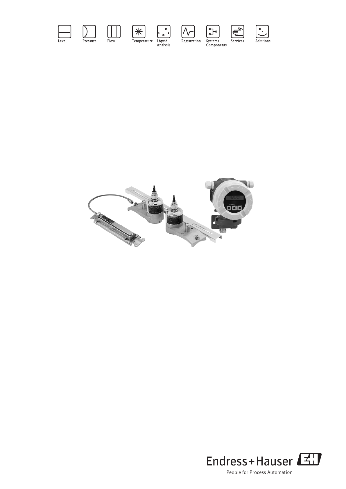
Measuring principle The measuring system operates on the principle of transit time difference. In this measurement method,
acoustic (ultrasonic) signals are transmitted between two sensors. The signals are sent in both directions,
i.e. the sensor in question works as both a sound transmitter and a sound receiver.
As the propagation velocity of the waves is less when the waves travel against the direction of flow than along
the direction of flow, a transit time difference occurs. This transit time difference is directly proportional to the
flow velocity.
A0013117
Principle of the transit time difference measurement method
Q = v · A
aSensor
bSensor
Q Volume flow
v Flow velocity (v & t )
t Transit time difference (t = t
A Pipe cross-sectional area
– tb)
a
The measuring system calculates the volume flow of the fluid from the measured transit time difference and
the pipe cross-sectional area. In addition to measuring the transit time difference, the system simultaneously
measures the sound velocity of the fluid. This additional measured variable can be used to distinguish different
fluids or as a measure of product quality.
The measuring device can be configured onsite to suit the specific application using Quick Setup menus.
Endress+Hauser 3
Page 4
Proline Prosonic Flow 91W
Esc
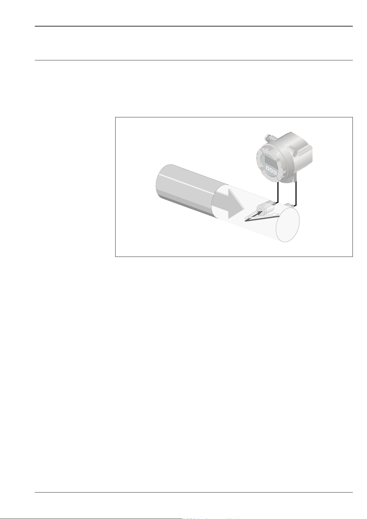
Measuring The measuring system consists of one transmitter and two sensors. Different versions are available depending
on the specific requirements.
The transmitter is used both to control the sensors and to prepare, process and evaluate the measuring signals,
and to convert the signals to a desired output variable.
The sensors work as sound transmitters and sound receivers. Depending on the application and version, the
sensors can be arranged for measurement via one or two traverses ä 5.
Transmitter
Prosonic Flow 91 W Field Housing
A0006022
Prosonic Flow W Prosonic Flow W
DN 15 to 65 (½" to 2½")
A0011484
DN 50 to 4000 (2" to 160")
A0013475
Mounting accessories
The requisite mounting distances must be determined for the sensors. Information on the fluid, the pipe
material used and the exact pipe dimensions is needed to determine these values. The values for the sound
velocity of the following fluids, pipe materials and lining materials are stored in the transmitter:
Fluid Pipe material Lining
•Water
•Sea water
• Distilled water
• Ammonia
• Alcohol
•Benzene
•Bromide
•Ethanol
•Glycol
•Kerosene
• Milk
• Methanol
• Toluene
•Lube oil
•Fuel Oil
•Petrol
• Carbon steel
• Ductile Iron
• Stainless steel
• Alloy C
•PVC
•PE
•LDPE
•HDPE
•PVDF
•PA
•PP
•PTFE
• Glass pyrex
•Mortar
• Rubber
• Tar Epoxy
4 Endress+Hauser
Page 5
Proline Prosonic Flow 91W
12
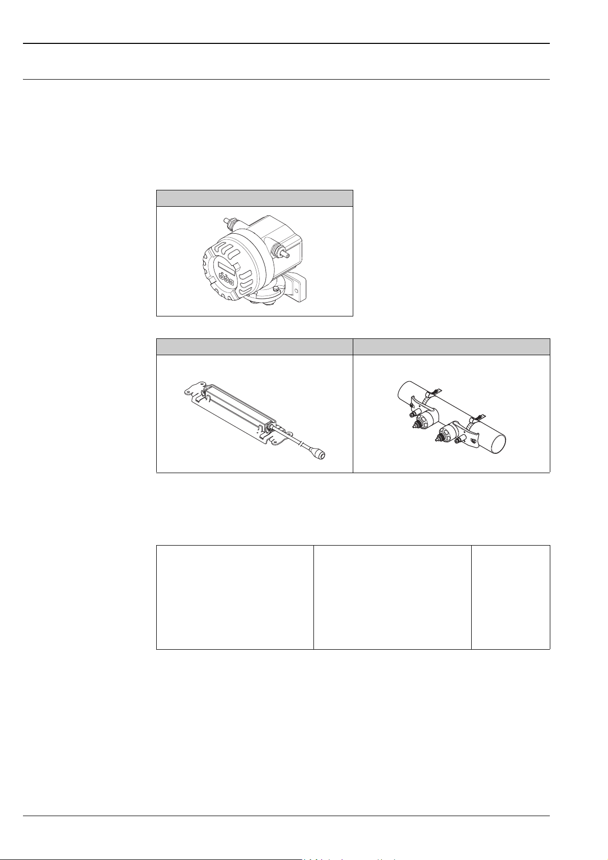
Sensor selection and arrangement
The sensors can be arranged in two ways:
• Mounting arrangement for measurement via one traverse:
the sensors are located on opposite sides of the pipe.
• Mounting arrangement for measurement via two traverses:
the sensors are located on the same side of the pipe.
A0005728
Sensor mounting arrangement (top view)
1 Mounting arrangement for measurement via one traverse
2 Mounting arrangement for measurement via two traverses
Recommendations
The number of traverses required depends on the sensor type, the nominal diameter and the thickness of the
pipe wall. We recommend the following types of mounting:
Sensor Type Nominal Diameter Sensor Frequency Sensor ID Type of Mounting
DN 15 to 65 (½" to 2 ½") 6 MHz W-CL-6F 2 traverses
3)
DN 80 (3") 2 MHz W-CL-2F 2 traverses
Prosonic Flow W
DN 100 to 300 (4" to 12") 2 MHz (or 1 MHz)
DN 300 to 600 (12" to 24") 1 MHz (or 2 MHz)
DN 650 to 2000 (26" to 80") 1 MHz (or 0.5 MHz)
1)
The installation of clamp-on sensors is principally recommended in the 2 traverse type installation. This type of
W-CL-2F
W-CL-1F
W-CL-1F
W-CL-2F
W-CL-1F
W-CL-05F
2 traverses
2 traverses
1 traverse
2)
2)
2)
installation allows the easiest and most comfortable type of mounting. However, in certain applications a 1 traverse
installation may be preferred:
• Certain plastic pipes with wall thickness > 4 mm (0.16 in)
• Lined pipes
• Applications with fluids with high acoustic damping
2)
0.5 MHz sensors are also recommended for applications with composite material pipes such as GRP and may be
recommended for certain lined pipes, pipes with wall thickness >10 mm (0.4 in), or applications with media with
high acoustic damping. In addition, for these applications we principally recommend mounting the W sensors in
a 1 traverse configuration.
3)
6 MHz sensors are recommended for applications where flow velocity is< 10 m/s (32.8 Hz/s)
1)
Endress+Hauser 5
Page 6

Input
Measured variable Flow velocity (differential delay proportional to flow velocity)
Measuring range Typically v = 0 to 15 m/s (0 to 50 ft/s) at the specified measuring accuracy
Operable flow range Over 150 : 1
Output
Output signal Current output:
• Galvanically isolated
• Full scale value adjustable
• Temperature coefficient: typ. 2 μA/°C, resolution: 1.5 μA
• Active: 4 to 20 mA, R
Pulse/status output:
• Galvanically isolated
• Open collector
• 30 V DC / 250 mA
• Passive
• Can be configured as:
– Pulse output: pulse value and pulse polarity can be selected, max. pulse width adjustable (5 to 2000 ms),
pulse frequency max. 100 Hz
– Status output: for example, can be configured for error messages, empty pipe detection, flow recognition,
limit value
< 700 (for HART: RL 250 )
L
Proline Prosonic Flow 91W
Signal on alarm • Current output failsafe mode selectable.
• Pulse/frequency output failsafe mode selectable
Load See “Output signal”
Low flow cutoff Switching point for the low flow freely selectable.
Galvanic isolation All circuits for inputs, outputs, and power supply are galvanically isolated from each other.
6 Endress+Hauser
Page 7
Proline Prosonic Flow 91W
eb
2127
–
25–26
+
24
+
L1
(L+)
N
(L-)
e
g
b
d
h
c
f
b
a
e
i
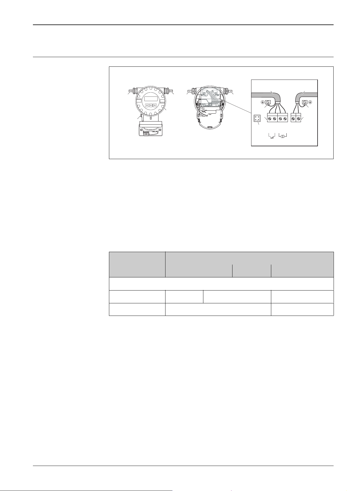
Measuring unit electrical connection
Power supply
Connecting the transmitter (Aluminium-Fieldhousing).
cable cross-section: max. 2.5 mm
aCover
b Cable for power supply: 85 to 260 V AC, 20 to 55 V AC, 16 to 62 V DC
c Terminal for power supply:
d Terminal for power supply: Nr. 1–2 (terminal assignment)
e Signal cable
f Ground terminal für signal cable
g Terminal connector for signal cable: Nr. 24–27 (terminal assignment)
h Service connector
i Ground terminal for potential matching
(AWG 13)
a0005838
Terminal assignment Prosonic Flow 91W
Order variant Terminal No. (inputs/outputs)
24 (+)/25 (–) 26 (+)/27 (–) 1 (L1/L+) /2 (N/L–)
Fixed communication boards (fixed assignment)
91***-***********A Pulse output HART current output Power supply
Functional values see "Output signal" see "supply voltage"
Endress+Hauser 7
Page 8
Proline Prosonic Flow 91W
ab
d
c
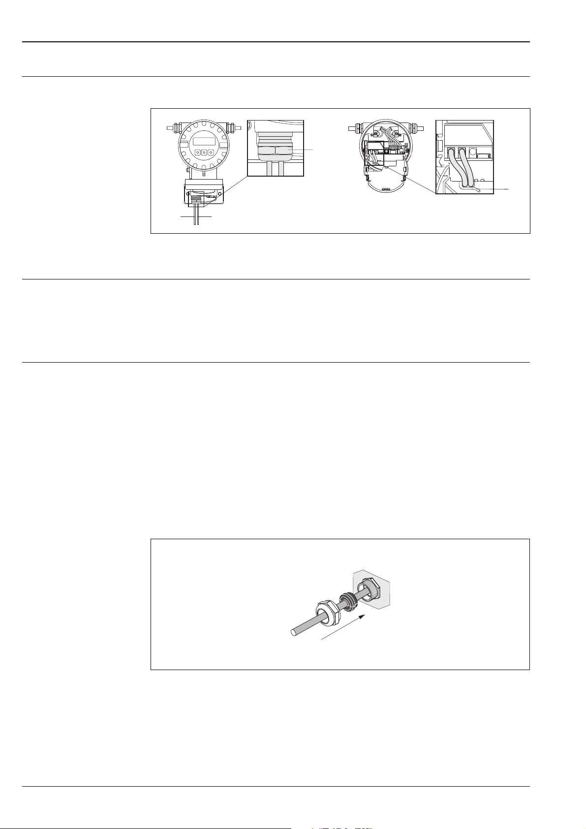
Connecting the connecting
Connection sensor cable in the electronics compartment
cable
a, b Sensor connection cable
c Cable gland holder
d Cable gland
Supply voltage Transmitter
85 to 260 V AC, 45 to 65 Hz
20 to 55 V AC, 45 to 65 Hz
16 to 62 V DC
Sensor
Powered by the transmitter
A0015907
Cable entry Power supply and signal cables (inputs/outputs)
• Cable entry M20 × 1.5 (8 to 12 mm; 0.31 to 0.47 in)
• Cable gland for cables, 6 to 12 mm ( 0.24" to 0.47")
• Thread for cable entries ½" NPT, G ½"
Connection cable (sensor /transmitter)
Cable glands for one multicore connection cable (1 ×
• Cable gland M20 × 1.5
• Thread for cable entries ½" NPT, G ½"
Connection cable (sensor /transmitter)
Cable glands for two single core connection cable (2 ×
• Cable gland M20 × 1.5
• Thread for cable entries ½" NPT, G ½"
The Prosonic Flow W DN 15 to 65 (½ to 2½") is grounded via the cable gland.
8 mm) per cable entry
4 mm) per cable entry
Cable gland for one multicore connection cable (1 ×8 mm /0.31 in) per cable entry
8 Endress+Hauser
a0016008
Page 9

Proline Prosonic Flow 91W
A0008152
Cable gland for two connection cables (2 × Q 4 mm/0.16") per cable entry
Cable-specification Only use the connection cable supplied by Endress+Hauser. Different versions of the connecting cables are
available ä 21.
Prosonic Flow
• Cable material:
– Prosonic Flow 91W (DN 50 to 4000/ 2" to 160") PVC (standard) or optional PTFE
– Prosonic Flow 91W (DN 15 to 65 / ½" to 2½") TPE-V
• Cable length:
– For use in a non hazardous zone: 5 to 60 m (16.4 to 196.8 ft)
!
Note!
To ensure correct measuring results, route the connection cable well clear of electrical machines and switching
elements.
power consumption 85 to 250 V AC: <12 VA (incl. measuring sensor)
20 to 28 V AC: <7 VA (incl. measuring sensor)
11 to 40 V DC: <5 W (incl. measuring sensor)
Power supply failure Lasting min. 1 power cycle
HistoROM/T-DAT save measuring system data if the power supply fails
Potential equalization For potential equalization, no special measures are necessary.
Endress+Hauser 9
Page 10

Performance characteristics
0
0.5
2.0
3.5
%
m/s
2 4 6 8 10 12
b
c
a
Proline Prosonic Flow 91W
Reference operating conditions
• Fluid temperature: +28 °C ± 2 K
• Ambient temperature: +22 °C ± 2 K
• Warm-up period: 30 minutes
Installation:
• Sensor and transmitter grounded.
• The measuring sensors are mounted correctly.
Maximum measured error Measured error
The measured error depends on a number of factors. A distinction is made between the measured error of the
device (Prosonic Flow 91 = 0.5 % of the measured value) and an additional installation-specific measured error
(typically 1.5 % of the measured value) that is independent of the device.
The installation-specific measured error depends on the installation conditions on site, such as the nominal
diameter, wall thickness, real pipe geometry, fluid etc. The sum of the two measured errors is the measured
error at the measuring point.
Example of the measured error in a pipe with a nominal diameter DN > 200 (8")
a Measured error of the device (0.5 % o.r. ± 3 mm/s
b Measured error due to installation conditions (typically 1.5 % o.r.)
c Measured error at the measuring point: 0.5 % o.r. ± 3 mm/s + 1.5 % o.r. = 2 % o.r. ± 3 mm/s.
A0011347
Measured error at the measuring point
The measured error at the measuring point is made up of the measured error of the device
(0.5 % o.r.) and the measured error resulting from the installation conditions on site.
Given a flow velocity > 0.3 m/s (1 ft/s) and a Reynolds number > 10000, the following are typical error limits:
Nominal
diameter
DN 15 (½") ±0.5 % o.r. ± 5 mm/s + ±2.5 % o.r. ±3 % o.r. ± 5 mm/s
DN 25 to 200 ±0.5 % o.r. ± 7.5 mm/s + ±1.5 % o.r. ±2 % o.r. ±7.5 mm/s
> DN 200 ±0.5 % o.r. ± 3 mm/s + ±1.5 % o.r. ±2 % o.r. ± 3 mm/s
Device error limits +
Installation-specific
error limits (typical)
Error limits at the measuring point
(typical)
o.r. = of reading
Measurement Report
If required, the device can be supplied with a measurement report. To certify the performance of the device,
a measurement is performed under reference conditions. Here, the sensors are mounted on a pipe with a
nominal diameter of DN 100 (4").
The measurement report guarantees the following error limits of the device
(at a flow velocity > 0.3 m/s (1 ft/s) and a Reynolds number > 10000):
Nominal diameter Guaranteed error limits of the device
Prosonic Flow W DN 15 (½"), DN 25 (1"), DN 40 (1½"), DN 50 (2") ±0.5 % o.r. ± 5 mm/s
Prosonic Flow W DN 100 (4") ±0.5 % o.r. ± 7.5 mm/s
Guaranted error limits of the device
o.r. = of reading
Repeatability Max. ± 0.3 % for flow velocity > 0.3 m/s (1 ft/s)
10 Endress+Hauser
Page 11

Proline Prosonic Flow 91W
A
B
CC
Operating conditions: installation
Installation instructions Mounting location
Correct flow measurement is possible only if the pipe is full. It is preferable to install the sensors in a riser.
!
Note!
Entrained air or gas bubbles in the measuring tube can result in an increase in measuring errors.
For this reason, avoid the following mounting locations:
• Highest point of a pipeline. Risk of air accumulating.
• Directly upstream of a free pipe outlet in a vertical pipe. Risk of partial pipe filling.
A0001103
Orientation
Vertical
Recommended orientation with upward direction of flow (View A). With this orientation, entrained solids will
sink and gases will rise away from the sensor when the fluid is stagnant. The piping can be completely drained
and protected against solids buildup.
Horizontal
In the recommended installation range in a horizontal installation position (View B), gas and air collections at
the pipe cover and problematic deposits at the bottom of the pipe have a smaller influence on measurement.
a0001105
A Vertical
BHorizontal
C Recommended installation range max. 120°
Endress+Hauser 11
Page 12

Proline Prosonic Flow 91W
1
2
3
³ 15xDN
³ 3xDN
³ 20xDN
³ 15xDN
³ 20xDN
Inlet and outlet runs If possible, install the sensor well clear of assemblies such as valves, T-pieces, elbows, etc. If several flow
obstructions are installed, the longest inlet or outlet run must be considered. Compliance with the following
requirements for the inlet and outlet runs is recommended to ensure measuring accuracy.
Inlet and outlet runs (top view)
1Valve (2/3 open)
2Pump
3 Two pipe bends in different directions
A0013079
Connection cable Route the cable well clear of electrical machines and switching elements
Cable specification ä 8
Operating conditions: environment
Ambient temperature range Transmitter
–25 to +60 °C (–13 to +140 °F)
At ambient temperatures below –20 °C (–4 °F) the readability of the display may be impaired.
Install the transmitter at a shady location. Avoid direct sunlight, particularly in warm climatic regions.
Sensor Prosonic Flow W
–20 to +80 °C (–4 to +176 °F)
Optional: 0 to +130 °C (–32 to +265 °F)
It is permitted to insulate the sensors mounted on the pipe.
Connecting cable (sensor/transmitter)
• Standard (TPE-V): –20 to +80 °C (–4 to 175 °F) (multi core, sensor DN 15 to 65 / ½" to 2½")
• Standard (PVC): –20 to +70 °C (–4 to 158 °F) (single core, sensor DN 50…4000 /2" to 160")
• Optional (PTFE): –40 to +170 °C (–40 to 338 °F) (single core, sensor DN 50…4000 /2" to 160")
• It is permitted to insulate the sensors mounted on the pipes.
• Mount the transmitter in a shady location and avoid direct sunlight, particulary in warm climatic regions.
!
Note!
Can be used with the version for 0…130 °C /-32…256 °F.
Storage temperature The storage temperature corresponds to the operating temperature range of the measuring transmitter and the
12 Endress+Hauser
appropriate measuring sensors and the corresponding sensor cable (see above).
Page 13

Proline Prosonic Flow 91W
Q
Esc
E
-
+
T1
T2
Degree of protection Transmitter
IP 67 (NEMA 4X)
Sensors
IP 67 (NEMA 4X)
Optional: IP 68 (NEMA 6P)
Shock and vibration resistance according to IEC 68-2-6
Operating conditions: process
Medium temperature range –20 to +80 °C (–4 to +176 °F)
Optional: 0 to +130 °C (32 to +265 °F)
Medium pressure range
Perfect measurement requires that the static fluid pressure is higher than vapor pressure, to avoid outgasing.
(nominal pressure)
Pressure loss There is no pressure loss.
Energy Measurement The Prosonic Flow 91W Ultrasonic is well suited for making or retrofitting energy measurement for hot or
chilled water systems - often used in conjunction with Endress+Hauser Flow and Energy Manager
RMC621/RMS621.
The quantity of heat is calculated from the process variable for flow and the differential from the feed and return
temperature. Energy Manager can also determine the quantity of heat in water flow from process variable flow
and a single temperature measurement.
Installation of delta heat measurement
• Temperature measurement takes place via two separate sensors which are directly connected to the
Endress+Hauser Energy Manager. (Temperature sensors and Energy Manager supplied separately).
• The Prosonic Flow 91W can be installed on either the hot or cold side of the heat exchanger.
Layout for delta heat measurement of hot or chilled water system
Endress+Hauser 13
A0013111
Page 14

Mechanical construction
Esc
E
-
+
190 (7.48)
178 (7.0)
~150 (~5.9)
113(4.45)
==
Ø 8.6 (M8) (0.34)
200 (7.87)
150 (5.9)
Ø 129 (5.1)
mm (inch)
100 (3.94)
80 (3.15)
52 (2.0)
50 (1.97)
190 (7.48)
Esc
E
-
+
A
Esc
E
-
+
B
80
(3.15)
172.5 (6.79)
&
185 ( 3.34)
&
mm (inch)
Design, dimensions Dimensions field housing
Proline Prosonic Flow 91W
A0006063-ae
Dimensions pipe mounting
a0005819
14 Endress+Hauser
Page 15

Proline Prosonic Flow 91W
B
A C
E
F
D
Prosonic Flow W sensor (DN 15 to 65 / ½" to 2½")
A0011502
Mounting arrangement for measurement via one traverse
Dimensions in SI units
A B C D E F
72 331 39 28 233 450
All dimensions in [mm]
Dimensions in US units
A B C D E F
2.83 13.03 1.54 1.10 .17 17.72
All dimensions in [inch]
Endress+Hauser 15
Page 16

Prosonic Flow W sensor (DN50 to 2000 / 2" to 80")
E
A
DB
I
C
H
G
F
Proline Prosonic Flow 91W
Mounting arrangement for measurement via two traverse
Dimensions in SI units
A B C D E F
56 62 145 111 58 Max. 872
G H
Depends on the measuring point conditions (pipe, fluid etc.).
Dimension "H" can be determined:
• by the transmitter prior to the mounting (Quick Setup or FieldCare)
• when specifying the flowmeter (online (Applicator)
All dimensions in [mm]
Pipe outer diameter
Dimensions in US units
A B C D E F
2.20 2.44 5.71 4.37 2.28 Max. 34.3
G H
Depends on the measuring point conditions (pipe, fluid etc.).
Dimension "H" can be determined:
• by the transmitter prior to the mounting (Quick Setup or FieldCare)
• when specifying the flowmeter (online (Applicator)
All dimensions in [inch]
Pipe outer diameter
A0011401
16 Endress+Hauser
Page 17

Proline Prosonic Flow 91W
E
DH
A
B
G
C
F
Prosonic Flow W sensor (DN50 to 2000 / 2" to 80")
Mounting arrangement for measurement via one traverse
Dimensions in SI units
A B C D E F
56 62 145 111 58 Max. 872
G H
Depends on the measuring point conditions (pipe, fluid etc.).
Dimension "H" can be determined:
• by the transmitter prior to the mounting (Quick Setup or FieldCare)
• when specifying the flowmeter (online (Applicator)
All dimensions in [mm]
Pipe outer diameter
Dimensions in US units
A B C D E F
2.20 2.44 5.71 4.37 2.28 Max. 34.3
G H
Depends on the measuring point conditions (pipe, fluid etc.).
Dimension "H" can be determined:
• by the transmitter prior to the mounting (Quick Setup or FieldCare)
• when specifying the flowmeter (online (Applicator)
All dimensions in [inch]
Pipe outer diameter
A0011155
Endress+Hauser 17
Page 18

Weight • Transmitter housing: 2.4 kg (5.2 lb)
• Flowrate measuring sensors W (clamp-on) incl. mounting rail and tensioning bands: 2.8 kg (6.2 lb)
Materials Transmitter
Wall-mounted housing: powder-coated die-cast aluminum
Sensor
• Sensor holder: stainless steel 1.4308/CF-8
• Sensor housing: stainless steel 1.4301/304
• Strapping bands/bracket: stainless steel 1.4301/304
• Sensor contact surfaces: chemically stable plastic
Connecting cable (sensor/transmitter)
• PVC/TPE-V connecting cable
– Cable sheath: PVC/TPE-V
– Cable connector: nickeled brass 2.0401/C38500
Human interface
Proline Prosonic Flow 91W
Display elements • Liquid crystal display: illuminated, two lines each with 16 characters
• Custom configuration for presenting different measured values and status variables
• 1 totalizer
Operating elements Local operation via three operating keys (S, O, F)
Remote operation Operation via HART protocol and FieldCare
Language group English, German, Spanish, Italian, French
18 Endress+Hauser
Page 19

Proline Prosonic Flow 91W
Certificates and approvals
CE mark The measuring system is in conformity with the statutory requirements of the EC Directives.
Endress+Hauser confirms successful testing of the device by affixing to it the CE mark.
C-Tick mark The measuring system is in conformity with the EMC requirements of the Australian Communications and
Media Authority (ACMA).
Ex approval Information about currently available Ex versions (FM, CSA) can be supplied by your Endress+Hauser Sales
Center on request. All explosion protection data are given in a separate documentation which is available upon
request.
Other standards and guidelines
• EN 60529
Degrees of protection provided by enclosures (IP code)
• EN 61010-1
Safety requirements for electrical equipment for measurement, control and laboratory use
• IEC/EN 61326
"Emission in accordance with Class A requirements".
Electromagnetic compatibility (EMC requirements).
• ANSI/ISA-S82.01
Safety Standard for Electrical and Electronic Test, Measuring, Controlling and Related
Equipment - General Requirements. Pollution Degree 2, Installation Category II.
• CAN/CSA-C22.2 No. 1010.1-92
Safety Requirements for Electrical Equipment for Measurement and Control and Laboratory Use.
Pollution degree 2
• NAMUR NE 21
Electromagnetic compatibility (EMC) of industrial process and laboratory control equipment.
• NAMUR NE 43
Standardization of the signal level for the breakdown information of digital transmitters with analog output
signal.
• NAMUR NE 53
Software of field devices and signal-processing devices with digital electronics.
Ordering information
The Endress+Hauser service organization can provide detailed ordering information and information on the
order codes on request.
Endress+Hauser 19
Page 20

Proline Prosonic Flow 91W
Accessories
Various accessories, which can be ordered separately from Endress+Hauser, are available for the transmitter
and the sensor. The Endress+Hauser service organization can provide detailed information on the order codes
on request.
Device-specific accessories
Device-specific accessories
Accessory Description Order code
Sensor W
(DN 15 to 65, (½" to 2½")
Clamp-on version
Sensor W
(DN 50 to 4000, (2" to 157")
Clamp-on version
Accessory Description Order code
Mounting kit for
aluminum field housing
Sensor holder set Prosonic Flow W (DN 15 to 65, ½" to 2½")
Clamp-on installation set Sensor fastening for Prosonic Flow W
DN 15 to 65, –20 to +80 °C (½" to 2 ½", –4 to +176 °F), 5.0 MHz
• IP 67 / NEMA 4X
• IP 68 / NEMA 6P
DN 15 to 65, 0 to +130 °C (½" to 2 ½", +32 to +266 °F), 5.0 MHz
• IP 67 / NEMA 4X
• IP 68 / NEMA 6P
DN 50 to 300, –20 to +80 °C (2" to 12", –4 to +176 °F), 2.0 MHz
• IP 67 / NEMA 4X
• IP 68 / NEMA 6P
DN 100 to 4000, –20 to +80 °C (4" to 160", –4 to +176 °F), 1.0 MHz
• IP 67 / NEMA 4X
• IP 68 / NEMA 6P
DN 100 to 4000, 0 to +130 °C (4" to 160", +32 to +266 °F), 1.0 MHz
• IP 67 / NEMA 4X DK9WS - P*
DN 50 to 300, 0 to +130 °C (2" to 12", +32 to +266 °F), 2.0 MHz
• IP 67 / NEMA 4X DK9WS - S*
DN 100 to 4000, –20 to +80 °C (4" to 160", –4 to +176 °F), 0.5 MHz
• IP 67 / NEMA 4X
• IP 68 / NEMA 6P
Mounting kit for wall-mount housing. DK9WM - C
• Sensor holder, clamp-on version
Prosonic Flow W (DN 50 to 4000, 2" to 160")
• Sensor holder, fixed retaining nut, clamp-on version
• Sensor holder, detachable retaining nut, clamp on version
DK9WS - 1*
DK9WS - 3*
DK9WS - 2*
DK9WS - 4*
DK9WS - B*
DK9WS - N*
DK9WS - A*
DK9WS - M*
DK9WS - R*
DK9WS - T*
DK9SH - 1
DK9SH - A
DK9SH - B
(DN 15 to 65, ½" to 2 ½")
• U-Bolt DN15-32 (½ to 1 ¼")
• Strapping bands DN 40 to 65 (1 ½ to 2 ½")
(DN 50 to 4000, 2" to 160")
• Without sensor fastening
• Strapping bands DN 50 to 200 (2" to 8")
• Strapping bands DN 200 to 600 (8" to 24")
• Strapping bands DN 600 to 2000 (24" to 80")
• Strapping bands DN 2000 to 4000 (80" to 160")
• Without mounting tools
• Spacing ruler DN 50 to 200 (2" to 8")
• Spacing ruler DN 200 to 600 (8" to 24")
• Fastener, 1 Traverse DN 50 to 4000 (2" to 160")
DK9IC - 11*
DK9IC - 21*
DK9IC - A*
DK9IC - B*
DK9IC - C*
DK9IC - D*
DK9IC - E*
DK9IC - *1
DK9IC - *2
DK9IC - *3
DK9IC - *6
20 Endress+Hauser
Page 21

Proline Prosonic Flow 91W
Accessory Description Order code
Conduit adapter for
connecting cable
Connecting cable For sensor DN 15 to 65, ½" to 2 ½"
Acoustic coupling fluid • Coupling fluid 0 to 170 °C (+32 to 338 °F), Standard
Prosonic Flow W (DN 15 to 65, ½" to 2 ½")
• Conduit adapter incl. cable entry M20 × 1,5
• Conduit adapter incl. cable entry ½" NPT
• Conduit adapter incl. cable entry G ½"
Prosonic Flow W (DN 50 to 4000, 2" to 160")
• Conduit adapter incl. cable entry M20 × 1,5
• Conduit adapter incl. cable entry ½" NPT
• Conduit adapter incl. cable entry G ½"
5 m (16 ft) sensor cable, TPE-V, –20 to +70 °C (–4 to 158 °F)
10 m (33 ft) sensor cable, TPE-V, –20 to +70 °C (–4 to 158 °F)
15 m (49 ft) sensor cable, TPE-V, –20 to +70 °C (–4 to 158 °F)
30 m (98 ft) sensor cable, TPE-V, –20 to +70 °C (–4 to 158 °F)
For sensor DN 50 to 4000, 2" to 160"
5 m (16 ft) sensor cable, PVC, –20 to +70 °C (–4 to 158 °F)
10 m (33 ft) sensor cable, PVC, –20 to +70 °C (–4 to 158 °F)
15 m (49 ft) sensor cable, PVC, –20 to +70 °C (–4 to 158 °F)
30 m (98 ft) sensor cable, PVC, –20 to +70 °C (–4 to 158 °F)
60 m (197 ft) sensor cable, PVC, –20 to +70 °C (–4 to 158 °F)
• Adhesive coupling fluid –40 to +80 °C (–40 to 176 °F)
• Water-soluble coupling fluid –20 to +80 °C (–4 to 176 °F)
• Coupling fluid DDU 19, –20 to +60 °C (–4 to 140 °F)
• Coupling fluid –40 to +100 °C (–40 to 212 °F), Standard,
type MBG2000
DK9CB - AA1
DK9CB - AA2
DK9CB - AA3
DK9CB - AB1
DK9CB - AB2
DK9CB - AB3
DK9SS - AAA
DK9SS - AAB
DK9SS - AAC
DK9SS - AAD
DK9SS - ABA
DK9SS - ABB
DK9SS - ABC
DK9SS - ABD
DK9SS - ABJ
DK9CM - 2
DK9CM - 3
DK9CM - 4
DK9CM - 6
DK9CM - 7
Communication-specific accessories
Accessory Description Order code
HART Communicator
Field Xpert SFX 100
Fieldgate FXA320 Gateway for remote interrogation of HART sensors and actuators
Fieldgate FXA520 Gateway for remote interrogation of HART sensors and actuators
FXA195 The Commubox FXA195 connects intrinsically safe Smart
Handheld terminal for remote configuration and for obtaining
measured values via the HART current output (4 to 20 mA).
Contact your Endress+Hauser representative for more
information.
via Web browser:
• 2-channel analog input (4 to 20 mA)
• 4 binary inputs with event counter function and frequency
measurement
• Communication via modem, Ethernet or GSM
• Visualization via Internet/Intranet in the Web browser and/or
WAP cellular phone
• Limit value monitoring with alarm signaling via e-mail or SMS
• Synchronized time stamping of all measured values.
via Web browser:
• Web server for remote monitoring of up to 30 measuring points
• Intrinsically safe version [EEx ia]IIC for applications in
hazardous areas
• Communication via modem, Ethernet or GSM
• Visualization via Internet/Intranet in the Web browser and/or
WAP cellular phone
• Limit value monitoring with alarm signaling via e-mail or SMS
• Synchronized time stamping of all measured values
• Remote diagnosis and remote configuration of
connected HART devices
transmitters with HART protocol to the USB port of a personal
computer. This makes the remote operation of the transmitters
possible with the aid of configuration programs (e.g. FieldCare).
Power is supplied to the Commubox by means of the USB port
SFX100 – *******
FXA320 - *****
FXA520 - ****
FXA195 – *
Endress+Hauser 21
Page 22

Proline Prosonic Flow 91W
Service-specific accessories
Accessory Description Order code
Applicator Software for selecting and planning flowmeters.
Fieldcheck Tester/simulator for testing flowmeters in the field.
FieldCare FieldCare is Endress+Hauser's FDT-based plant asset
FXA291 Service interface from the measuring device to the PC for
Memograph M graphic
display recorder
The Applicator can be downloaded from the Internet or
ordered on CD-ROM for installation on a local PC.
Contact your Endress+Hauser representative for more
information.
When used in conjunction with the "FieldCare" software
package, test results can be imported into a database, printed
out and used for official certification.
Contact your Endress+Hauser representative for more
information.
management tool. It can configure all intelligent field units
in your system and helps you manage them.
By using the status information, it is also a simple but
effective way of checking their status and condition.
operation via FieldCare.
The Memograph M graphic display recorder provides
information on all the relevant process variables. Measured
values are recorded correctly, limit values are monitored and
measuring points analyzed. The data are stored in the 256
MB internal memory and also on a DSD card or USB stick.
Memograph M boasts a modular design, intuitive operation
and a comprehensive security concept. The ReadWin
PC software is part of the standard package and is used for
configuring, visualizing and archiving the data captured.
The mathematics channels which are optionally available
enable continuous monitoring of specific power
consumption, boiler efficiency and other parameters which
are important for efficient energy management.
®
DXA80 - *
50098801
See the product page on the
Endress+Hauser Web site:
www.endress.com
FXA291 – *
RSG40-************
2000
22 Endress+Hauser
Page 23

Proline Prosonic Flow 91W
Documentation
• Flow measurement (FA005D/06)
• Operating Instructions for Prosonic Flow 91 (BA100D/06)
• Supplementary documentation on Ex-ratings: FM, CSA
Registered trademarks
HART®
Registered trademark of HART Communication Foundation, Austin, USA
HistoROM™, T-DAT™, FieldCare®, Field Xpert™, Fieldcheck
Registered or registration-pending trademarks of Endress+Hauser Flowtec AG, Reinach, CH
®
Endress+Hauser 23
Page 24

Instruments International
Endress+Hauser
Instruments International AG
Kaegenstrasse 2
4153 Reinach
Switzerland
Tel.+41 61 715 81 00
Fax+41 61 715 25 00
www.endress.com
info@ii.endress.com
TI00105D/06/EN/13.11
71136725
FM+SGML6.0 ProMoDo
 Loading...