

Page 1
KA01200G/00/EN/01.16
71320492
Products Solutions Services
Brief Operating Instructions
Proservo NMS80
Tank Gauging
These Instructions are Brief Operating Instructions; they are
not a substitute for the Operating Instructions pertaining to
the device.
Detailed information about the device can be found in the
Operating Instructions and the other documentation:
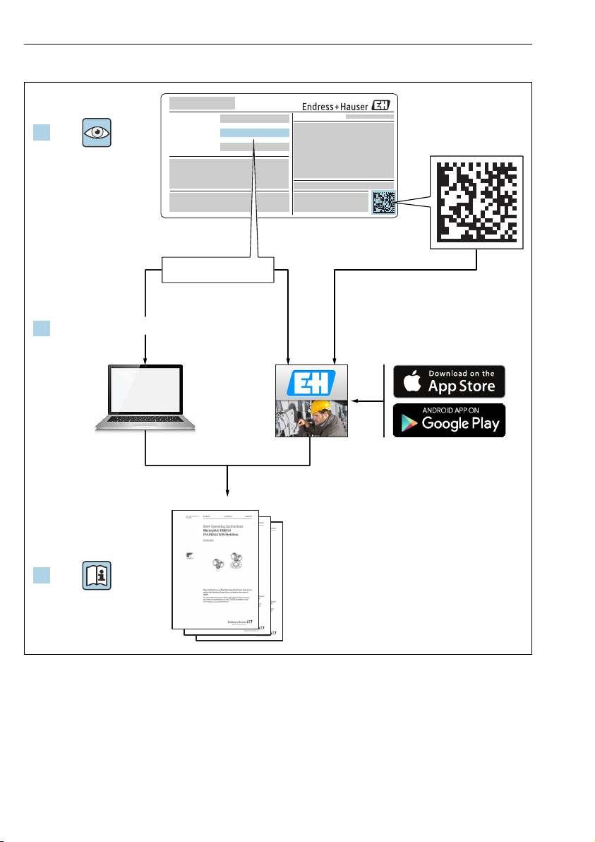
Available for all device versions via:
– Internet: www.endress.com/deviceviewer
– Smart phone/tablet: Endress+Hauser Operations App
Page 2
Proservo NMS80
1.
Order code:
Ext. ord. cd.:
Ser. no.:
www.endress.com/deviceviewer Endress+Hauser Operations App
XXXXXXXXXXXX
XXXXX-XXXXXX
XXX.XXXX.XX
Serial number
2.
3.
A0023555
2 Endress+Hauser
Page 3

Proservo NMS80 Table of contents
Table of contents
1 About this document ............................................................. 4
1.1 Symbols ............................................................................ 4
2 Basic safety instructions ......................................................... 6
2.1 Requirements for the personnel ........................................................... 6
2.2 Designated use ....................................................................... 6
2.3 Workplace safety ...................................................................... 7
2.4 Operational safety ..................................................................... 7
2.5 Product safety ........................................................................ 7
3 Product description .............................................................. 8
3.1 Product design ....................................................................... 8
4 Incoming acceptance and product identification .................................. 9
4.1 Incoming acceptance ................................................................... 9
4.2 Product identification .................................................................. 9
4.3 Storage and transport .................................................................. 9
5 Installation ..................................................................... 10
5.1 Requirements ....................................................................... 10
5.2 Mounting of the device ................................................................ 15
6 Electrical connection ............................................................ 27
6.1 Terminal assignment .................................................................. 27
6.2 Connecting requirements ............................................................... 37
6.3 Ensuring the degree of protection ........................................................ 38
6.4 Post-connection check ................................................................. 38
7 Commissioning ................................................................. 39
7.1 Operating methods ................................................................... 39
7.2 Terms related to tank measurement ....................................................... 42
7.3 Setting the display language ............................................................ 43
7.4 Calibration ......................................................................... 44
7.5 Configuration of the inputs ............................................................. 52
7.6 Linking measured values to tank variables .................................................. 56
7.7 Configuration of the limit evaluation ...................................................... 57
7.8 Configuration of the signal output ........................................................ 58
Endress+Hauser 3
Page 4
About this document Proservo NMS80
DANGER
WARNING
CAUTION
NOTICE
1 About this document
1.1 Symbols
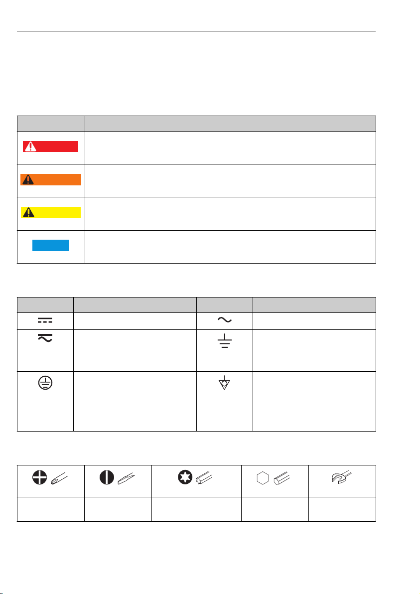
1.1.1 Safety symbols
Symbol Meaning
DANGER!
This symbol alerts you to a dangerous situation. Failure to avoid this situation will result in
serious or fatal injury.
WARNING!
This symbol alerts you to a dangerous situation. Failure to avoid this situation can result in
serious or fatal injury.
CAUTION!
This symbol alerts you to a dangerous situation. Failure to avoid this situation can result in
minor or medium injury.
NOTE!
This symbol contains information on procedures and other facts which do not result in personal
injury.
1.1.2 Electrical symbols
Symbol Meaning Symbol Meaning
Direct current Alternating current
Direct current and alternating current Ground connection
Protective ground connection
A terminal which must be connected to
ground prior to establishing any other
connections.
A grounded terminal which, as far as
the operator is concerned, is grounded
via a grounding system.
Equipotential connection
A connection that has to be connected
to the plant grounding system: This
may be a potential equalization line or
a star grounding system depending on
national or company codes of practice.
1.1.3 Tool symbols
Flat blade
screwdriver
A0011220
A0013442 A0011221
Torx screwdriver Allen key Hexagon wrench
A0011219
Cross-head
screwdriver
4 Endress+Hauser
A0011222
Page 5
Proservo NMS80 About this document
,…,
,…,
-
.
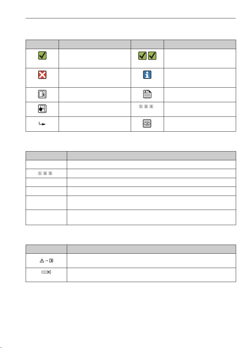
1.1.4 Symbols for certain types of information
Symbol Meaning Symbol Meaning
Permitted
Procedures, processes or actions that
are permitted.
Forbidden
Procedures, processes or actions that
are forbidden.
Reference to documentation Reference to page
Preferred
Procedures, processes or actions that
are preferred.
Tip
Indicates additional information.
Reference to graphic
Result of a sequence of actions Visual inspection
1.1.5 Symbols in graphics
Symbol Meaning
1, 2, 3 ... Item numbers
Series of steps
A, B, C, ... Views
A-A, B-B, C-C, ... Sections
Hazardous area
Indicates a hazardous area.
Safe area (non-hazardous area)
Indicates the non-hazardous area.
1.1.6 Symbols at the device
Symbol Meaning
Safety instructions
Observe the safety instructions contained in the associated Operating Instructions.
Temperature resistance of the connection cables
Specifies the minimum value of the temperature resistance of the connection cables.
Series of steps
Endress+Hauser 5
Page 6

Basic safety instructions Proservo NMS80
2 Basic safety instructions
2.1 Requirements for the personnel
The personnel must fulfill the following requirements for its tasks:
Trained, qualified specialists must have a relevant qualification for this specific function
‣
and task
Are authorized by the plant owner/operator
‣
Are familiar with federal/national regulations
‣
Before beginning work, the specialist staff must have read and understood the instructions
‣
in the Operating Instructions and supplementary documentation as well as in the
certificates (depending on the application)
Following instructions and basic conditions
‣
2.2 Designated use
Application and measured materials
Depending on the version ordered, the measuring device can also measure potentially
explosive, flammable, poisonous and oxidizing media.
Measuring devices for use in hazardous areas, in hygienic applications or in applications
where there is an increased risk due to process pressure, are labeled accordingly on the
nameplate.
To ensure that the measuring device remains in proper condition for the operation time:
Only use the measuring device in full compliance with the data on the nameplate and the
‣
general conditions listed in the Operating Instructions and supplementary documentation.
Check the nameplate to verify if the device ordered can be put to its intended use in the
‣
approval-related area (e.g. explosion protection, pressure vessel safety).
Use the measuring device only for media against which the process-wetted materials are
‣
adequately resistant.
If the measuring device is not operated at atmospheric temperature, compliance with the
‣
relevant basic conditions specified in the associated device documentation is absolutely
essential.
Protect the measuring device permanently against corrosion from environmental
‣
influences.
Observe the limit values in the "Technical Information".
‣
The manufacturer is not liable for damage caused by improper or non-designated use.
Residual risk
During operation the sensor may assume a temperature near the temperature of the
measured material.
Danger of burns due to heated surfaces!
For high process temperatures: Install protection against contact in order to prevent burns.
‣
6 Endress+Hauser
Page 7

Proservo NMS80 Basic safety instructions
2.3 Workplace safety
For work on and with the device:
Wear the required personal protective equipment according to federal/national
‣
regulations.
2.4 Operational safety
Risk of injury.
Operate the device in proper technical condition and fail-safe condition only.
‣
The operator is responsible for interference-free operation of the device.
‣
Conversions to the device
Unauthorized modifications to the device are not permitted and can lead to unforeseeable
dangers.
If, despite this, modifications are required, consult with the manufacturer.
‣
Repair
To ensure continued operational safety and reliability,
Carry out repairs on the device only if they are expressly permitted.
‣
Observe federal/national regulations pertaining to repair of an electrical device.
‣
Use original spare parts and accessories from the manufacturer only.
‣
Hazardous area
To eliminate a danger for persons or for the facility when the device is used in the hazardous
area (e.g. explosion protection, pressure vessel safety):
Based on the nameplate, check whether the ordered device is permitted for the intended
‣
use in the hazardous area.
Observe the specifications in the separate supplementary documentation that is an integral
‣
part of these Instructions.
2.5 Product safety
This measuring device is designed in accordance with good engineering practice to meet stateof-the-art safety requirements, has been tested, and left the factory in a condition in which it
is safe to operate. It meets general safety standards and legal requirements.
2.5.1 CE mark
The measuring system meets the legal requirements of the applicable EC guidelines. These are
listed in the corresponding EC Declaration of Conformity together with the standards applied.
Endress+Hauser confirms successful testing of the device by affixing to it the CE mark.
Endress+Hauser 7
Page 8
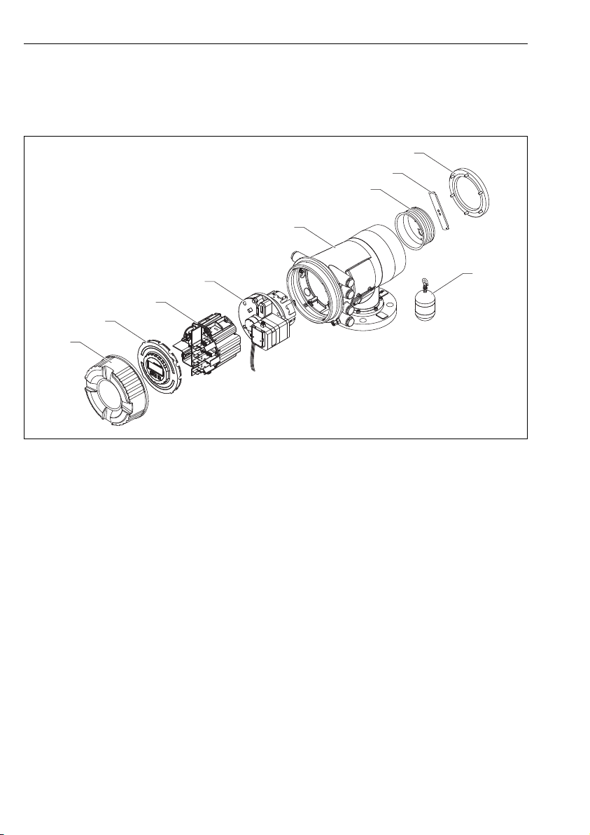
Product description Proservo NMS80
2
3
5
6
7
8
4
9
3 Product description
3.1 Product design
A0030105
1 Configuration of NMS80
1 Front cover
2 Display
3 Modules
4 Sensor unit
5 Housing
6 Wire drum
7 Bracket
8 Rear cover
9 Displacer
8 Endress+Hauser
Page 9

Proservo NMS80 Incoming acceptance and product identification
4 Incoming acceptance and product identification
4.1 Incoming acceptance
Upon receipt of the goods check the following:
• Are the order codes on the delivery note and the product sticker identical?
• Are the goods undamaged?
• Do the nameplate data match the ordering information on the delivery note?
• If required (see nameplate): Are the Safety Instructions (XA) enclosed?
If one of these conditions is not satisfied, contact your Endress+Hauser Sales Center.
4.2 Product identification
The following options are available for identification of the measuring device:
• Nameplate specifications
• Extended order code with breakdown of the device features on the delivery note
• Enter serial numbers from nameplates in W@M Device Viewer
( www.endress.com/deviceviewer ): All information about the measuring device is
displayed.
• Enter the serial number from the nameplates into the Endress+Hauser Operations App or
scan the 2-D matrix code (QR code) on the nameplate with the Endress+Hauser Operations
App: all the information for the measuring device is displayed.
For an overview of the scope of the associated Technical Documentation, refer to the
following:
• The W@M Device Viewer: Enter the serial number from the nameplate
(www.endress.com/deviceviewer)
• The Endress+Hauser Operations App: Enter the serial number from the nameplate or scan
the 2-D matrix code (QR code) on the nameplate.
4.3 Storage and transport
4.3.1 Storage conditions
• Storage temperature: –50 to +80 °C (–58 to +176 °F)
• Store the device in its original packaging.
4.3.2 Transport
NOTICE
Risk of injury
Transport the measuring device to the measuring point in its original packaging.
‣
Take into account the mass center of the device in order to avoid unintended tilting.
‣
Comply with the safety instructions, transport conditions for devices over 18kg (39.6lbs)
‣
(IEC61010).
Endress+Hauser 9
Page 10
Installation Proservo NMS80
2
1
3
7
4
8
12
13
9
10
11
5
6
100 (3.94)
B
D
A
C
5 Installation
5.1 Requirements
5.1.1 Mounting with guide wires
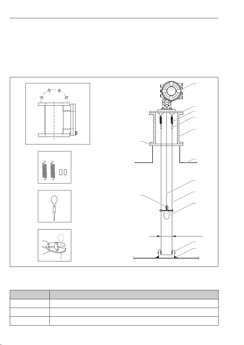
It is also possible to guide the displacer with guide wires to prevent swinging.
2 Guide wire; dimensions mm (in)
No. Description
A Calibration chamber
B Spring and sleeve
C Guide wire sleeve
10 Endress+Hauser
A0026819
Page 11
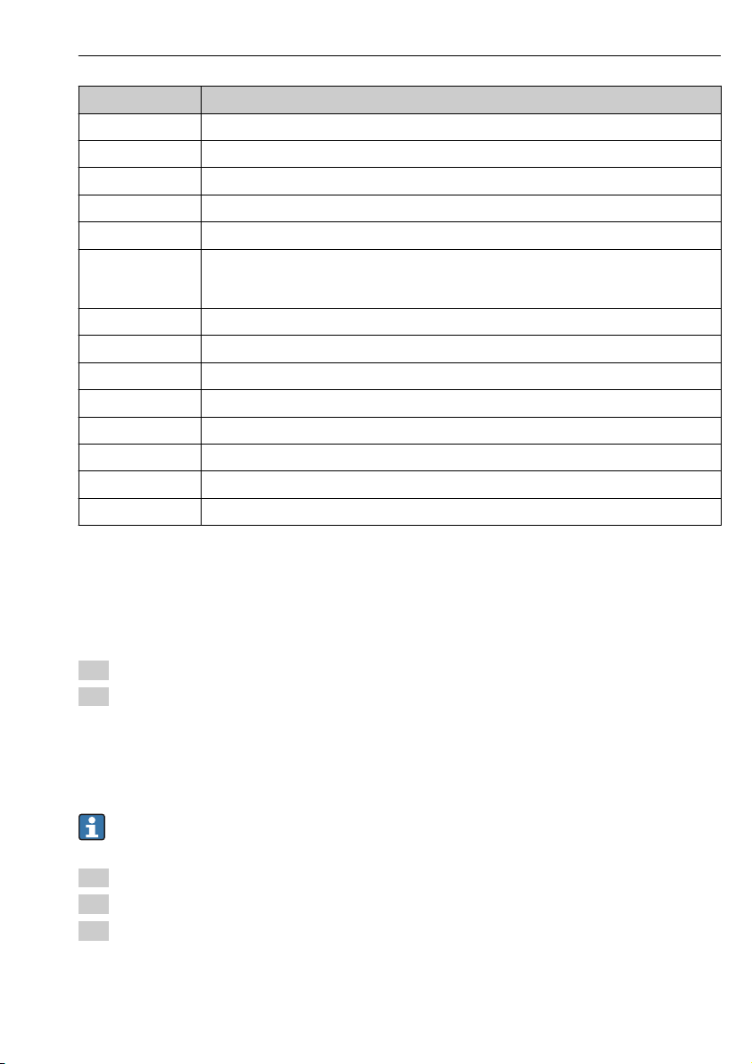
Proservo NMS80 Installation
No. Description
D Crimp tool
1 NMS8x
2 Reducer plate
3 Spring, SUS304
4 Sleeve, SUS316
5
6 Tank
7 Measuring wire
8 Guide wire, SUS316
9 Displacer
10 Anchor hook plate, SUS304
11 Welding point
12 Ring, SUS316
13 Flange
1) Reducer pipe for low pressure: 6 mm (0.236 in)
2) Reducer flange material is selectable from SS400 and SUS304.
Calibration chamber for maintenance
NHC4HP for high pressure, SCS13 equivalent to SUS304
NHC4LP for low pressure, SCS13 equivalent to SUS304
1) 2)
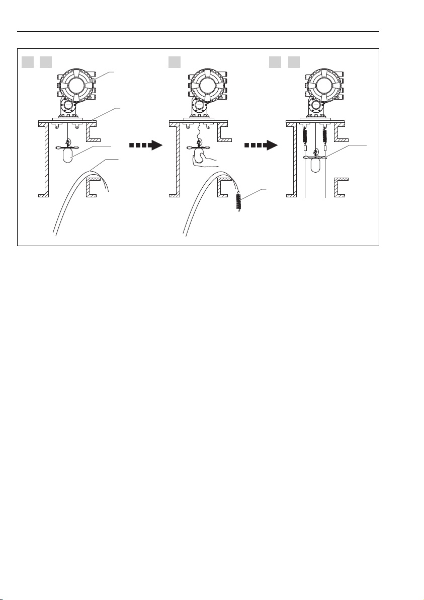
Guide wire installation
Guide wire installation procedure
1. Install NMS8x [1] on the reducer plate.
2. Perform calibration steps (→ 44) before the displacer [3] is attached to the guide
wires.
Make sure that the displacer does not touch the guide wires during calibration. This
could be done by mounting the NMS8x to the reducer plate [2] prior to fitting the
guide wires [4].
Perform calibration steps so that displacer does not touch the guide wires if the guide
wires are already installed to the reducer plate.
3. Secure the guide wires to the hooks of the springs [5].
4. Secure the springs to the reducer plate.
5. Put the guide wires through the displacer guide ring [6] and set the displacer.
This completes the guide wire installation procedure.
Endress+Hauser 11
Page 12
Installation Proservo NMS80
6
2
3
1
4
5
1. 2. 3. 4. 5.
A0026887
3 Guide wire installation
1 NMS8x
2 Reducer plate
3 Displacer
4 Guide wires
5 Springs
6 Displacer guide ring
12 Endress+Hauser
Page 13
Proservo NMS80 Installation
+1°
-1°
1
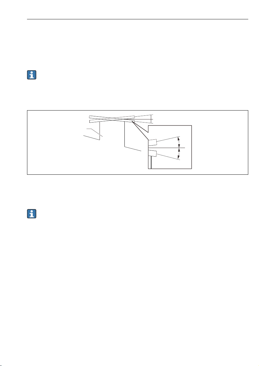
5.1.2 Alignment of NMS8x Flange
Confirm that the size of the nozzle and the flange is matched prior to mounting NMS8x on
the tank. The flange size and the rating of NMS8x vary depending on the customer’s
specifications.
• Check the flange size of NMS8x.
• Mount the flange on the top of the tank. The deviation of the flange from the
horizontal plane should not exceed +/- 1 degree.
• When mounting NMS8x on a long nozzle, make sure that the displacer does not touch
the inner wall of the nozzle.
A0026889
4 Allowable inclination of mounting flange
1 Nozzle
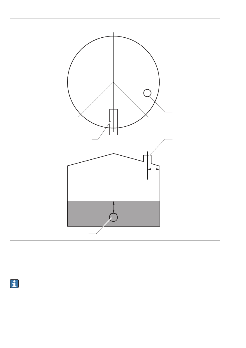
When NMS8x is installed without a guide system, follow the recommendations below:
• Confirm the mounting nozzle is in the sector between 45 and 90 degrees (or -45 and
-90 degrees)away from the inlet pipe of the tank. This prevents heavy swinging of the
displacer caused by waves or turbulence from the inlet liquid.
• Confirm the mounting nozzle is 500 mm (19.69 in) or more away from the tank wall.
• Confirm the minimum measuring level is at 500 mm (19.69 in) or more above the top
of the inlet pipe by setting the low stop (for details of low stop setting, refer to
"Commissioning" in the separate BA (Instruction Manual)). This protects the displacer
from direct flow of the inlet liquid.
• If a stilling well cannot be mounted in the tank due to the shape or condition of the
tank, attaching a guide system is recommended. Consult E+H services for further
information.
Endress+Hauser 13
Page 14
Installation Proservo NMS80
≥500 (19.69)
90°-90°
0°
45°-45°
1
1
≥500 (19.69)
2
2
5 Recommended position for mounting NMS8x and minimum measuring level; dimensions mm (in)
1 Inlet pipe
2 Tank nozzle
• Before pouring liquid into the tank, confirm that liquid flowing through the inlet of the
A0026890
pipe will not contact the displacer directly.
• When discharging liquid out of the tank, ensure that the displacer will not get caught
in the liquid current and sucked into the outlet pipe.
14 Endress+Hauser
Page 15
Proservo NMS80 Installation
5.1.3 Electrostatic charge
When liquid measured by NMS8x has a conductivity of 1 uS/m or less, it is quasinonconductive. In this case, using a stilling well or guide wire is recommended. This releases
the electrostatic charge on the liquid surface.
5.2 Mounting of the device
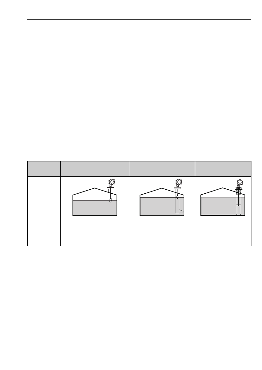
The NMS8x is delivered in two different packing styles depending on the mounting method of
the displacer.
• For the all-in-one method, the displacer is mounted on the measuring wire of NMS8x.
• For the displacer shipped separately method, it is necessary to install the displacer on the
measuring wire inside NMS8x.
5.2.1 Available installations
The following installation procedures are available for NMS8x.
• Mounting without guide system
• Mounting with stilling well
• Mounting with guide wire
Mounting
options
Type of tanks
Type of
installations
Without guide system
(Free-space mounting)
• All-in one
• Displacer shipped separately
• Displacer installation through
calibration window
With stilling well With guide wire
• All-in one
• Displacer shipped separately
• Displacer installation through
calibration window
Displacer shipped separately
Endress+Hauser 15
Page 16
Installation Proservo NMS80
316L
50
ml
70.8
ml
141.6
g
256.6
Ø
B
V
D
V
D
m
NMS8
Displacer
712xxxxx
Spare part-no.:
12345678901
Ser.no.:
Ø
0.15
HNBR
mm
302.xxx
m
28
WireDia.
O-Ring
Cir.
Range
NMS8
Wiredrum
712xxxxx
Spare part-no.:
98765432109
Ser.no.:
712xxxxx
Spare part-no.:
HNBR
O-Ring
28m
Range
NMS8
98765432109
Ser. no.:
3
1.
2.
12345678901
712xxxxxx
m 256.6g
D
V 141.6mL
D
V 70.8mL
B
!50 316L
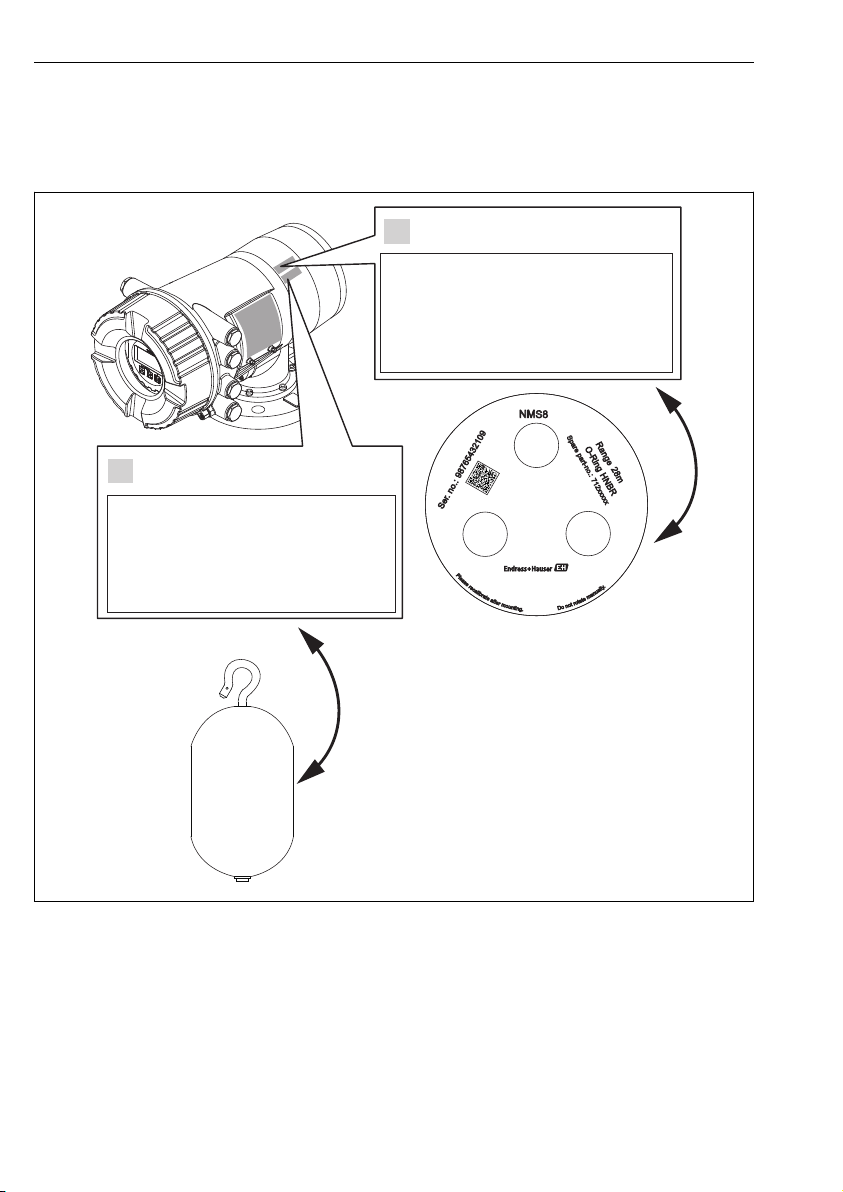
5.2.2 Verification of displacer and wire drum
Prior to installation of NMS8x, confirm that the serial numbers of displacer and the wire drum
match with those printed to the label attached on the housing.
A0030106
6 Verification of displacer and wire drum
16 Endress+Hauser
Page 17
Proservo NMS80 Installation
4
2
3
5
6
1
1.
2.
3.
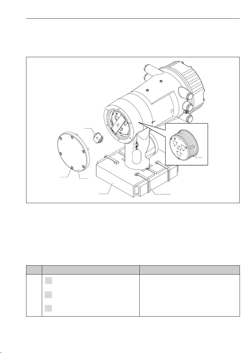
5.2.3 Installation for all-in-one method
In the case of a 50 mm (1.97 in) or 70 mm (2.76 in) diameter displacer, the device can be
delivered by all-in-one method.
A0030108
7 Removing packing materials
1 Tape
2 Fixing band
3 Displacer holder
4 Wire drum stopper
5 Drum housing cover
6 Screws and bolts
Steps Procedures Notes
1
Endress+Hauser 17
Hold the gauge so that it stays horizontal
against the flange.
Cut the fixing bands [2].
Remove the displacer holder [3] and packing
material of the displacer.
• Perform these steps before mounting NMS8x on
the nozzle.
• Do not tilt NMS8x after removing the displacer
holder.
Page 18
Installation Proservo NMS80
4.
5.
6.
7.
8.
9.
Steps Procedures Notes
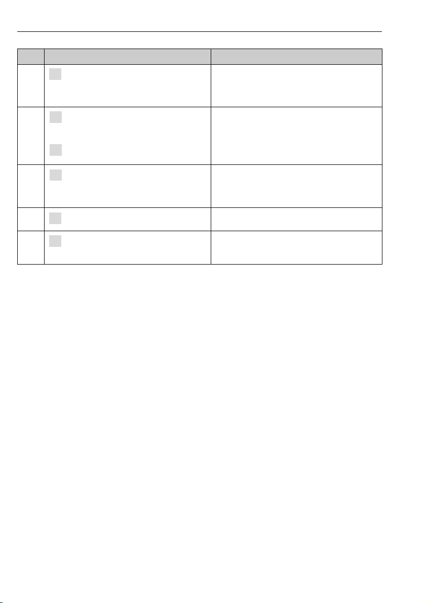
Mount NMS8x on the nozzle. • Make sure that the measuring wire hangs
2
Remove screws and M6 bolts [6] (M10 bolts
for stainless steel housing) to remove the
3
4
5
drum housing cover [5].
Loosen two screws and remove the wire drum
stopper [4].
Remove the tape [1] from the wire drum
carefully.
Mount the drum housing cover. Confirm that the O-ring is in the drum housing cover.
vertically.
• Confirm that there are no kinks or other defects in
the measuring wire.
Be sure not to lose the O-ring and the fixing bolts for
the cover of the drum housing.
• Remove the tape by hand to avoid damaging the
wire drum.
• Make sure that the measuring wire is wound so
that it fits correctly in the grooves.
6
Turn on the power of NMS8x.
Sensor, reference, and drum calibration steps
are not required because they are all performed
prior to delivery.
18 Endress+Hauser
Page 19
Proservo NMS80 Installation
200 (7.87)
200 (7.87)
130 (5.12) 130 (5.12)
1.
2.
1
4
2
5
3.
4.
5.
6.
7.
8.
9.
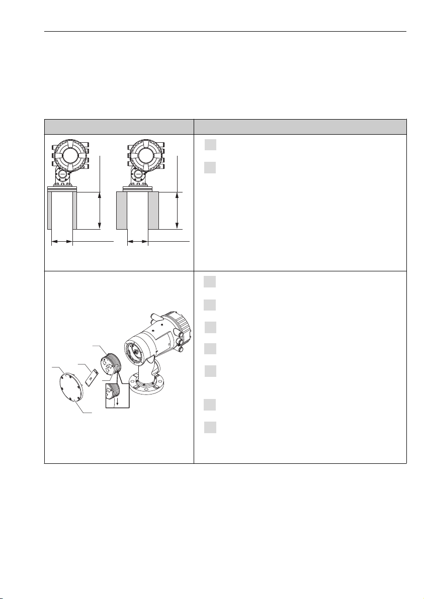
5.2.4 Installation for displacer shipped separately method
It is necessary to remove the wire drum from NMS8x, remove the tape on the wire drum,
mount the wire drum in the drum housing, and install the displacer on the measuring wire.
Use blocks or a pedestal to secure NMS8x and provide an environment where electrical power
can be supplied to NMS8x.
Figures Procedures
Secure NMS8x on the blocks or pedestal.
Confirm that there is enough space under NMS8x.
Be careful not to drop NMS8x.
Dimensions mm (in)
Remove screws and M6 bolts [5] (M10 bolts for stainless
steel housing).
Remove the wire drum cover [3] and the bracket [2].
Endress+Hauser 19
A0030109
Remove the wire drum [1] from the drum housing.
Remove the tape [4] on the wire drum.
Unwind the measuring wire approximately
250 mm (9.84 in) so that the wire ring is positioned under
the flange.
Mount the wire drum on NMS8x.
Mount the bracket.
• Handle the measuring wire with care. It may kink.
• Be sure that the wire is wound correctly in the grooves.
Page 20
Installation Proservo NMS80
1
3
2
10.
1
2
3
4
5
11.
12.
13.
14.
15.
16.
17.
Figures Procedures
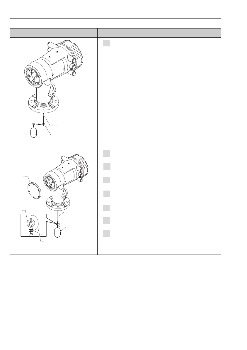
Hook the displacer [3] on the ring [2].
• Be sure that the wire is wound correctly in the grooves.
• If not, remove the displacer and the wire drum, and repeat
step 7.
A0030110
Turn on the power of NMS8x.
Perform sensor calibration
Secure the displacer [2] to the measuring wire [1] using the
securing wire [4].
Install the ground wire [3] of the displacer (for details of
displacer ground wire installation → 24).
Perform reference calibration.
Turn off the power.
Mount the wire drum cover [5].
A0030111
• For sensor calibration, → 47
• For reference calibration, → 49.
20 Endress+Hauser
Page 21
Proservo NMS80 Installation
1
18.
19.
20.
21.
Figures Procedures
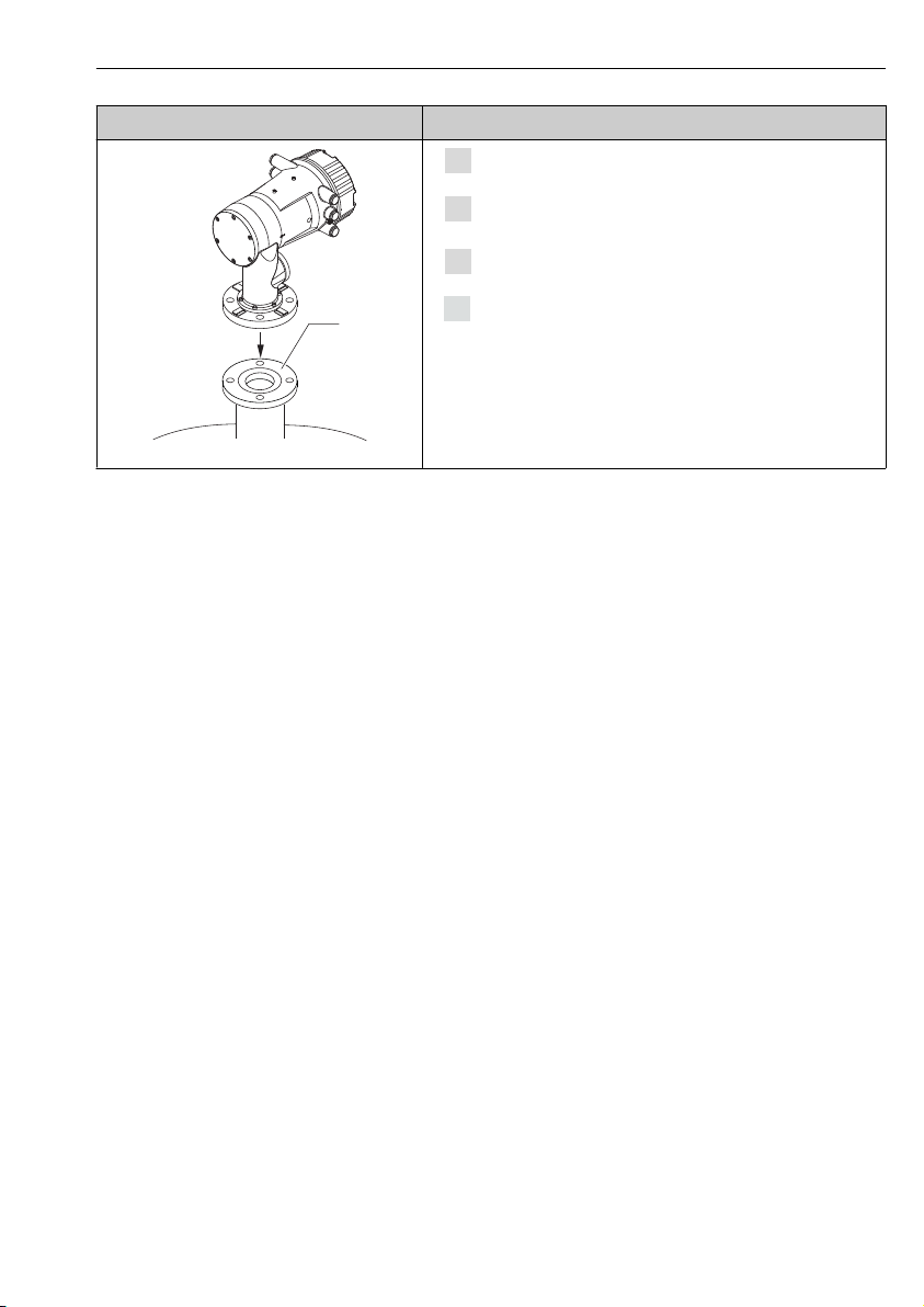
Mount NMS8x on the tank nozzle [1].
Confirm that the displacer does not touch the inner wall of
the nozzle.
Turn on the power.
Perform drum calibration.
For drum calibration, → 50
A0030112
Endress+Hauser 21
Page 22
Installation Proservo NMS80
1
1.
4
1
2
3
5
2.
3.
4.
5.
2
1
3
4
6.
7.
8.
9.
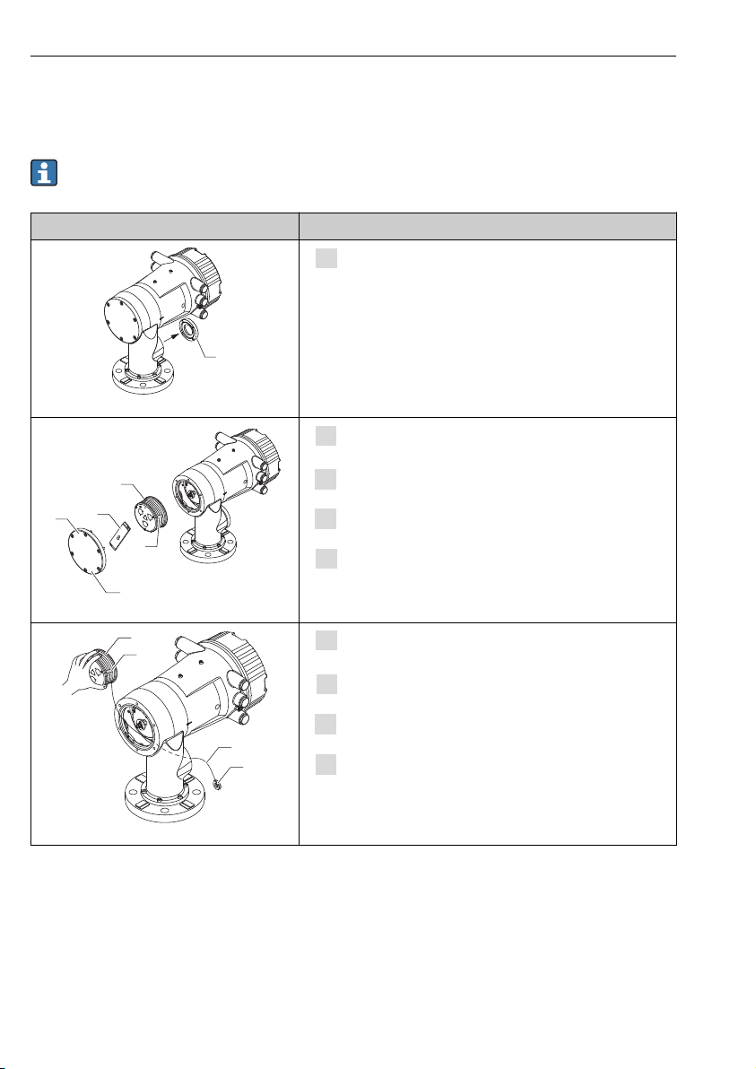
5.2.5 Installation through the calibration window
In the case of a 50 mm (1.97 in) diameter displacer, the displacer can be installed through the
calibration window.
It is only possible to install the following displacers through the calibration window:
50 mm SUS, 50 mm alloy C, 50 mm PTFE
Figures Procedures
Remove the calibration window cover [1].
A0030113
Remove M6 bolts and screws [5] (M10 bolts for stainless
steel housing).
Remove the cover [4] and the bracket [3].
Remove the wire drum [1] from the drum housing.
Remove the tape [2] that is securing the wire.
Handle the measuring wire with care. It may kink.
A0030114
Holding the wire drum [1] with one hand, unwind the
measuring wire [3] approximately 500 mm (19.69 in).
Secure the wire [3] temporarily with the tape [2].
Insert the wire ring [4] into the drum housing.
Pull the wire ring out through the calibration window.
Handle the measuring wire with care.
A0030115
22 Endress+Hauser
Page 23
Proservo NMS80 Installation
3
1
2
4
10.
11.
12.
13.
2
1
14.
15.
16.
17.
18.
2
1
5
4
19.
20.
21.
22.
23.
24.
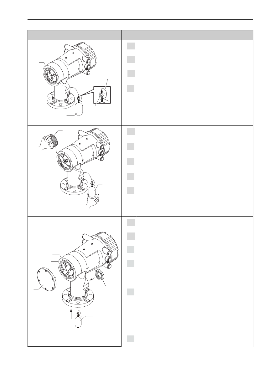
Figures Procedures
Insert the wire drum [4] temporarily into the drum housing.
Hook the displacer [3] on the wire ring.
Secure the displacer to the measuring wire using the
securing wire [2].
Install the ground wire [1] for the displacer (for details of
displacer ground wire installation → 24).
Handle the measuring wire with care. It may kink.
A0030116
Hold the wire drum [1] up and place the displacer [2] into
the calibration window.
Remove the wire drum from the drum housing and unwind
the measuring wire approximately 500 mm (19.69 in).
Hold the wire drum up and place the displacer into the
calibration window.
Hold the displacer at the center of the calibration window.
Hold the other hand (wire drum) up to add tension to the
measuring wire in order not to drop the displacer rapidly.
A0030117
Let go of the displacer [2].
Remove the tape from the wire drum [5].
Insert the wire drum into the drum housing.
Mount the bracket [4].
Be sure that the wire is wound correctly in the grooves.
A0030118
Turn on the power of NMS8x and move the displacer up
using the Move displacer wizard→ 46 until the wire
ring can be seen in the calibration window.
• Confirm that there are no kinks or other defects in the
measuring wire.
• Confirm that the displacer does not touch the inner wall of
the nozzle.
Perform sensor calibration.
Endress+Hauser 23
Page 24
Installation Proservo NMS80
25.
26.
27.
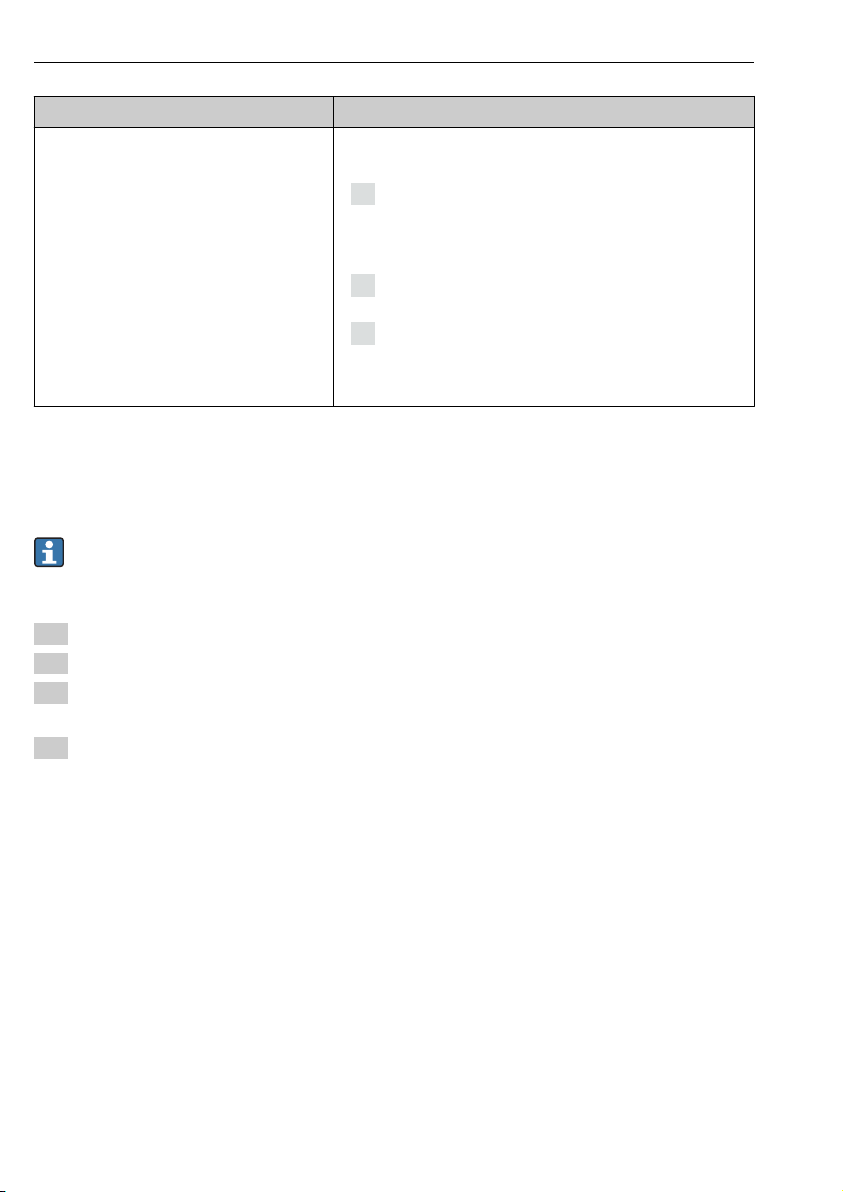
Figures Procedures
For sensor calibration, → 47
Perform reference calibration.
For reference calibration, → 49.
Mount the drum housing cover [3] and the calibration
window cover [1].
Perform drum calibration.
For drum calibration, → 50
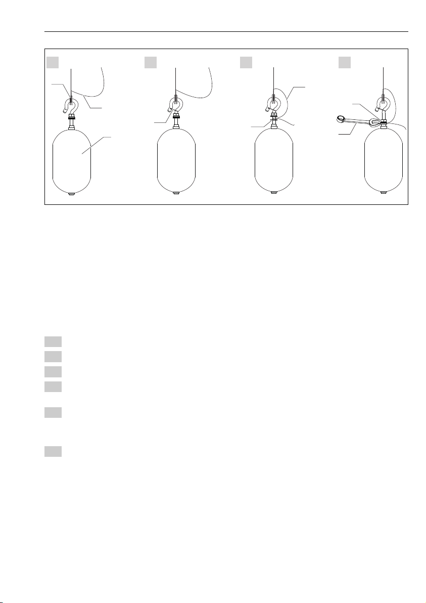
5.2.6 Displacer ground wire installation
Depending on the application and Ex requirements, electrical grounding of the displacer is
required. There are different procedures depending on the displacer type, which are described
below.
For details of displacer installation → 15
Standard displacer installation
1. Mount the displacer [3] on the wire ring [1].
2. Wind the securing wire [4] on the wire hook.
3. Wind the ground wire [2] between the washers [5] twice.
If grounding is not required for non-explosion-proof applications, skip this step.
4. Secure the nut [6] with a wrench [7].
This completes the displacer installation procedure.
24 Endress+Hauser
Page 25
Proservo NMS80 Installation
1
2
3
4
2
5
6
7
1. 2. 3. 4.
A0028694
8 Displacer installation
1 Wire ring
2 Ground wire
3 Displacer
4 Securing wire
5 Washer
6 Nut
7 Wrench
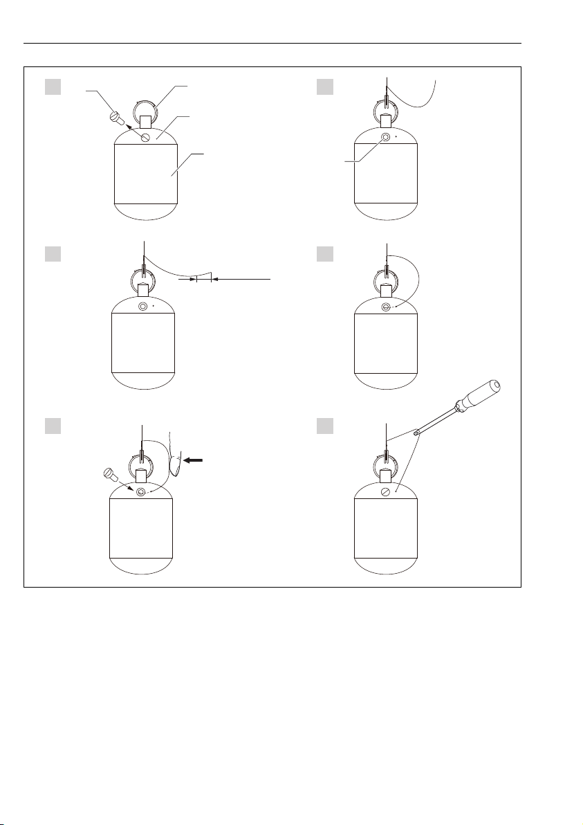
PTFE displacer installation
1. Remove the screw [1] using a flathead screwdriver.
2. Mount the displacer [4] on the PFA covered ring [2].
3. Remove the PFA cover approximately 10 mm (0.39 in) for conductivity.
4. Install the ground wire [6] onto the displacer from the wire insertion slot [3] until the
ground wire contacts to the wall of the screw hole [5].
5. Tighten the screw [1].
Hold the ground wire with finger tips so that the wire does not come out from the
slot.
6. Lift the displacer using a screwdriver and confirm that the ground wire does not come
out from the slot.
This completes the PTFE displacer installation.
Endress+Hauser 25
Page 26
Installation Proservo NMS80
1. 2.
3. 4.
5. 6.
1
2
3
4
5
10 (0.39)
9 PTFE displacer installation; dimensions mm (in)
1 Screw
2 PFA covered ring
3 Wire insertion slot
4 Displacer
5 Screw hole
6 Ground wire
A0028696
26 Endress+Hauser
Page 27
Proservo NMS80 Electrical connection
D
E
F
C
B
A
1
1
1
1 3
2
2 4
1
HR
CDI
WP
on
SIM
22334
4
112233445566778
8
i
G
1
3
2
POWER
D
E
F
C
B
A
1
1
1
1 3
2
2 4
1
HR
CDI
WP
on
SIM
22334
4
112233445566778
8
i
G
1
3
2
POWER
G1 N
G3 L
AC 85...264 V
6 Electrical connection
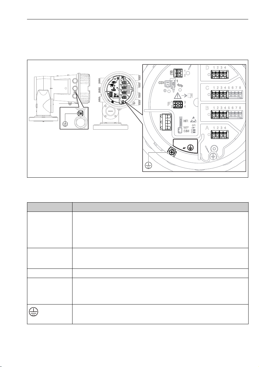
6.1 Terminal assignment
A0026905
10 Terminal compartment (typical example) and ground terminals
Terminal area Module
Up to four I/O modules, depending on the order code
A/B/C/D
(slots for I/O modules)
• Modules with four terminals can be in any of these slots.
• Modules with eight terminals can be in slot B or C.
The exact assignment of the modules to the slots is dependent on the device version
→ 28.
E HART Ex i/IS interface
• E1: H+
• E2: H-
F Remote display (in preparation)
Power supply: 85 to 264 V
G
• G1: N
• G2: not connected
AC
• G3: L
Protective ground connection
A0018339
Endress+Hauser 27
Page 28
Electrical connection Proservo NMS80
Spare parts for: Proservo NMS81
Ser.-no.:
8A21AC098AF4
Spare part
Spare no./structure
Displacer
Wire Drum
Additional information:
XPF0002-AABICR+
AAEAEBEFLALC76
XPF0002-AABEFEG+
XPF0002-AABEFEG+
XPF0002-AABEFEG+
XPF0002-AABEFEG+
XPF0002-AABEFEG+
XPF0002-AABEFEG+
XPF0002-AABEFEG+
XPF0002-AABEFEG+
71273689
7122xxxx
XPF0002-AABEFEG+
AAAAACDEFEG+
XPF0002-AAACABADJ+
AAHAHCHRIJJAJBKP
71023451
71023451
71023451
Cover
IOM-V1
IOM-A/RTD
IOM-D
SlotA
Slot B
Slot C
Slot D
IO Mod FF
Display
Display asm.
Detector
Main electr.
SMS electr.
6
7
8
9
10
11
12
5
4
3
2
1
www.endress.com/deviceviewer
9
4-8
2,3
1
11
10
12
D
C
B
A
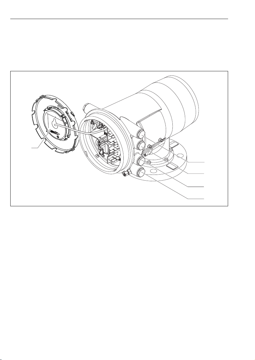
6.1.1 Slots for I/O modules
The terminal compartment contains four slots (A, B, C and D) for I/O modules. Depending on
the device version (ordering features 040, 050 and 060) these slots contain different I/O
modules. The slot assignment for the device at hand is indicated on a label attached to the
back cover of the display module.
A0030119
1 Label showing (among other things) the modules in the slots A to D.
A Cable entry for slot A
B Cable entry for slot B
C Cable entry for slot C
D Cable entry for slot D
28 Endress+Hauser
Page 29
Proservo NMS80 Electrical connection
D
E
F
C
B
A
1
1
1
1 3
2
2 4
1
HR
WP
on
SIM
2
23344
112233445566778
8
A
1 2 3 4
A1-4
i
D
1
2 3 4
D1-4
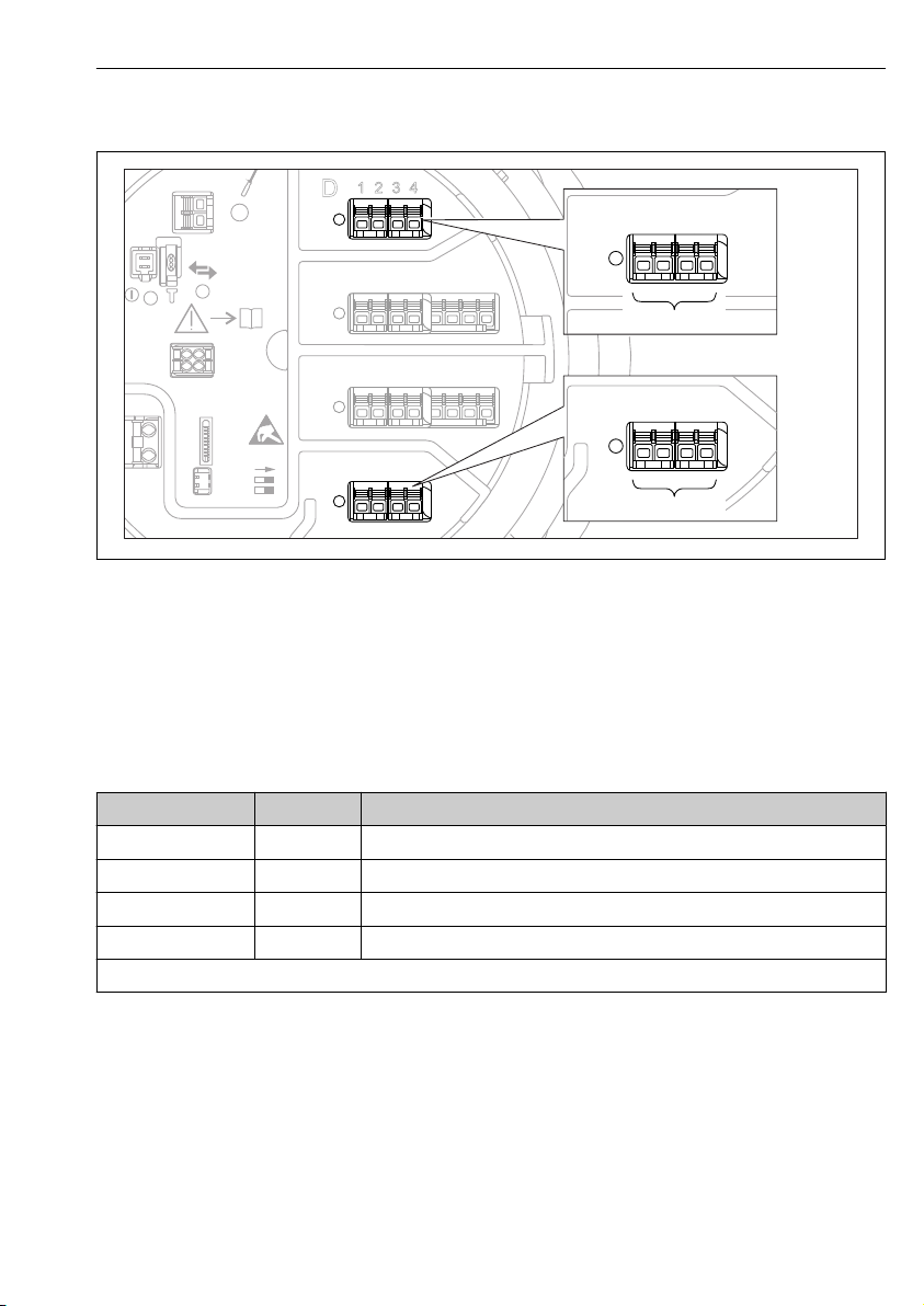
6.1.2 Terminals of the "Modbus" or "V1" module
A0031200
11 Designation of the "Modbus" or "V1" modules (examples); depending on the device version these
modules may also be in slot B or C.
Depending on the device version, the "Modbus" and/or "V1" module may be in different slots of
the terminal compartment. In the operating menu the "Modbus" and "V1" interfaces are
designated by the respective slot and the terminals within this slot: A1-4, B1-4, C1-4, D1-4.
Terminals of the "Modbus" module
1)
Terminal
X1 S Cable shielding connected via a capacitor to EARTH
X2 0V Common reference
X3 B- Non-inverting signal line
X4 A+ Inverting signal line
Designation of the module in the operating menu: Modbus X1-4; (X = A, B, C or D)
1) In this column, "X" stands for one of the slots "A", "B", "C", or "D".
Endress+Hauser 29
Name Description
Page 30
Electrical connection Proservo NMS80
D
E
F
C
B
A
1
1
1
1 3
2
2 4
1
HR
CDI
WP
on
SIM
22334
4
112233445566778
8
i
G
1
3
2
POWER
ca
b
-
+
!
E
G
F
1
1
1 3
2
2 4
HR
CDI
WP
on
SIM
i
D
C
B
A
1122334
4
112233445566778
8
G
1
3
2
POWER
Terminals of the "V1" module
1)
Terminal
Name Description
X1 S Cable shielding connected via capacitor to EARTH
X2 not connected
X3 B- Protocol loop signal -
X4 A+ Protocol loop signal +
Designation of the module in the operating menu: V1 X1-4; (X = A, B, C or D)
1) In this column, "X" stands for one of the slots "A", "B", "C", or "D".
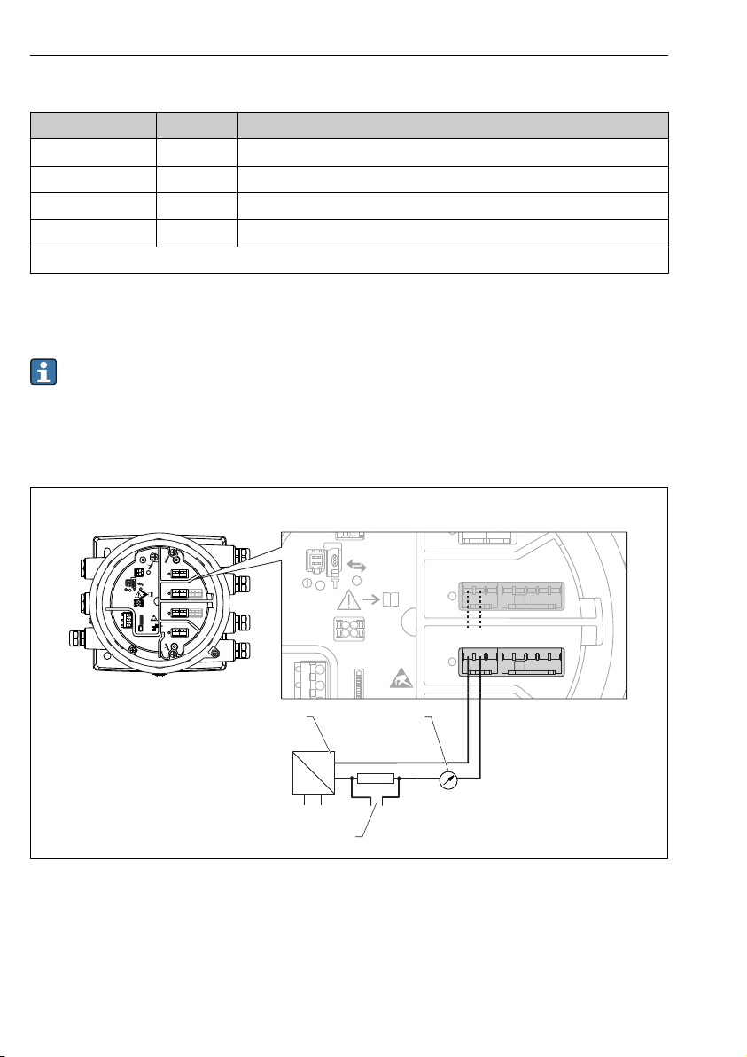
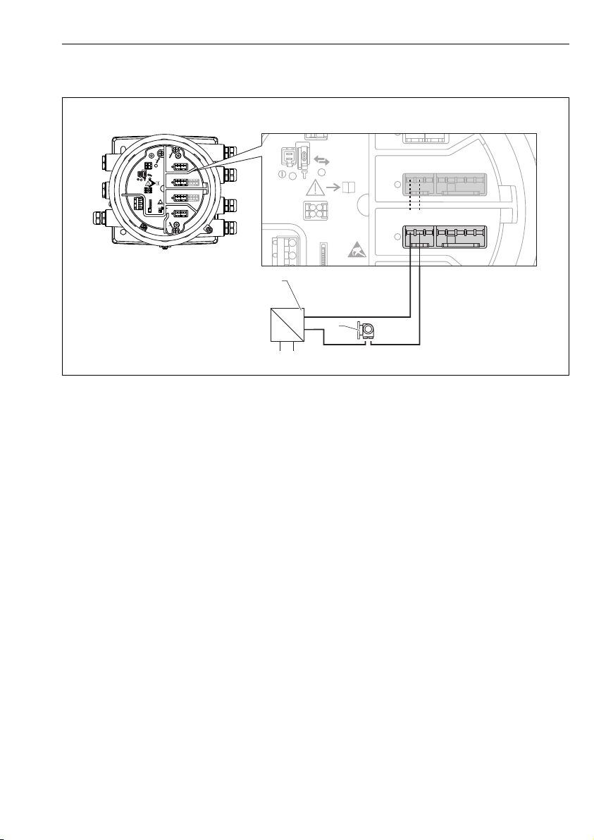
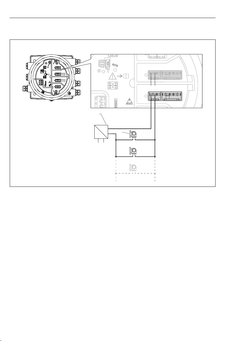
6.1.3 Connection of the "Analog I/O" module for passive usage
• In the passive usage the supply voltage for the communication line must be supplied by
an external source.
• The wiring must be in accordance with the intended operating mode of the Analog I/O
module (); see the drawings below.
"Operating mode" = "4..20mA output" or "HART slave +4..20mA output"
12 Passive usage of the Analog I/O module in the output mode
a Power supply
b HART signal output
c Analog signal evaluation
30 Endress+Hauser
A0027931
Page 31
Proservo NMS80 Electrical connection
D
E
F
C
B
A
1
1
1
1 3
2
2 4
1
HR
CDI
WP
on
SIM
22334
4
112233445566778
8
i
G
1
3
2
POWER
a
+
–
E
G
F
1
1
1 3
2
2 4
HR
CDI
WP
on
SIM
i
D
C
B
A
1122334
4
112233445566778
8
G
1
3
2
POWER
b
"Operating mode" = "4..20mA input" or "HART master+4..20mA input"
A0027933
13 Passive usage of the Analog I/O module in the input mode
a Power supply
b External device with 4...20mA and/or HART signal output
Endress+Hauser 31
Page 32
Electrical connection Proservo NMS80
D
E
F
C
B
A
1
1
1
1 3
2
2 4
1
HR
CDI
WP
on
SIM
22334
4
112233445566778
8
i
G
1
3
2
POWER
a
+
–
!
E
G
F
1
1
1 3
2
2 4
HR
CDI
WP
on
SIM
i
D
C
B
A
1122334
4
112233445566778
8
G
1
3
2
POWER
b
"Operating mode" = "HART master"
A0027934
14 Passive usage of the Analog I/O module in the HART master mode
a Power supply
b Up to 6 external devices with HART signal output
32 Endress+Hauser
Page 33
Proservo NMS80 Electrical connection
D
E
F
C
B
A
1
1
1
1 3
2
2 4
1
HR
CDI
WP
on
SIM
22334
4
112233445566778
8
i
G
1
3
2
POWER
b
a
-
+
E
G
F
1
1
1 3
2
2 4
HR
CDI
WP
on
SIM
i
D
C
B
A
1122334
4
112233445566778
8
G
1
3
2
POWER
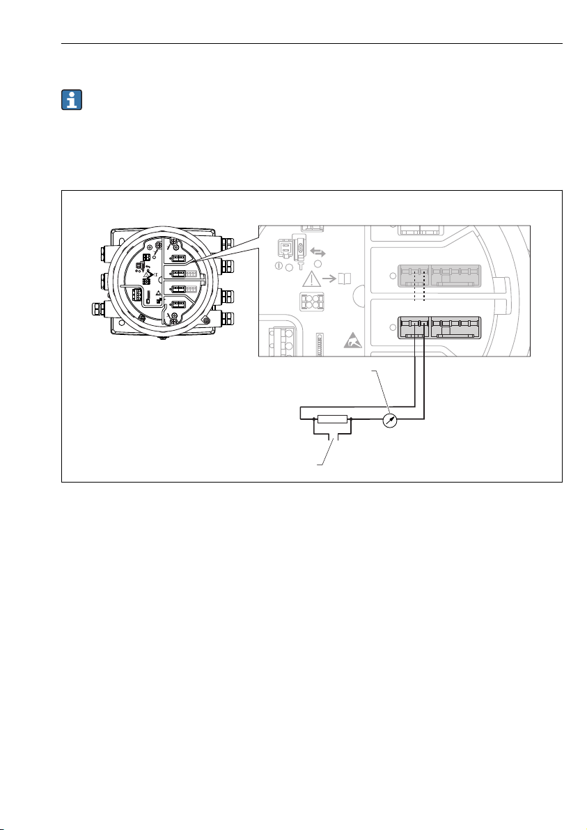
6.1.4 Connection of the "Analog I/O" module for active usage
• In the active usage the supply voltage for the communication line is supplied by the
device itself. There is no need of an external power supply.
• The wiring must be in accordance with the intended operating mode of the Analog I/O
module (); see the drawings below.
"Operating mode" = "4..20mA output" or "HART slave +4..20mA output"
15 Active usage of the Analog I/O module in the output mode
a HART signal output
b Analog signal evaluation
Endress+Hauser 33
A0027932
Page 34
Electrical connection Proservo NMS80
D
E
F
C
B
A
1
1
1
1 3
2
2 4
1
HR
CDI
WP
on
SIM
22334
4
112233445566778
8
i
G
1
3
2
POWER
E
G
F
1
1
1 3
2
2 4
HR
CDI
WP
on
SIM
i
D
C
B
A
1122334
4
112233445566778
8
G
1
3
2
POWER
-
+
a
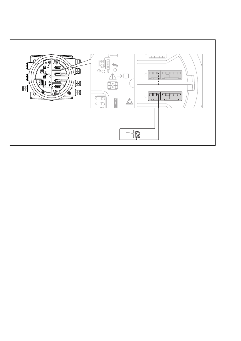
"Operating mode" = "4..20mA input" or "HART master+4..20mA input"
A0027935
16 Active usage of the Analog I/O module in the input mode
a External device with 4...20mA and/or HART signal output
34 Endress+Hauser
Page 35
Proservo NMS80 Electrical connection
D
E
F
C
B
A
1
1
1
1 3
2
2 4
1
HR
CDI
WP
on
SIM
22334
4
112233445566778
8
i
G
1
3
2
POWER
E
G
F
1
1
1 3
2
2 4
HR
CDI
WP
on
SIM
i
D
C
B
A
1122334
4
112233445566778
8
G
1
3
2
POWER
a
-
+
A
C
B
1 112 22
3 33
4 445 556 667 778 88
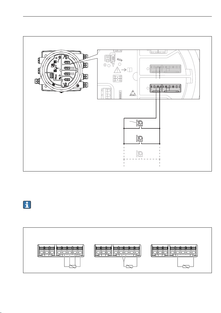
"Operating mode" = "HART master"
17 Active usage of the Analog I/O module in the HART master mode
a Up to 6 external devices with HART signal output
The maximum current consumption for the connected HART devices is 24 mA (i.e. 4 mA
per device if 6 devices are connected).
6.1.5 Connection of a RTD
A 4-wire RTD connection
B 3-wire RTD connection
C 2-wire RTD connection
Endress+Hauser 35
A0027936
A0026371
Page 36
Electrical connection Proservo NMS80
D
E
F
C
B
A
1
1
1
1 3
2
2 4
1
HR
WP
on
SIM
22334
4
1
122334455667788
A
1 2 3 4
A1-2 A3-4
i
C
1
2 3 4 5 6 7
C1-2 C3-4
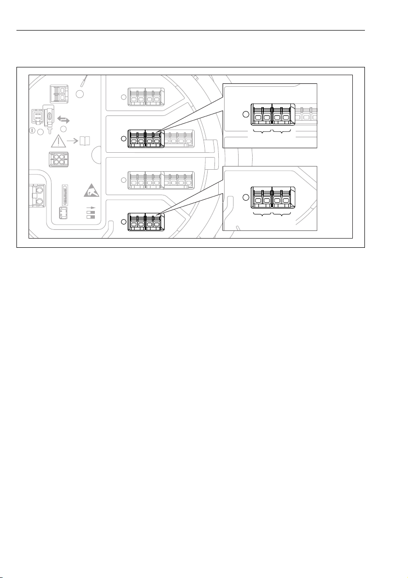
6.1.6 Terminals of the "Digital I/O" module
A0026424
18 Designation of the digital inputs or outputs (examples)
• Each Digital IO Module provides two digital inputs or outputs.
• In the operating menu each input or output is designated by the respective slot and two
terminals within this slot. A1-2, for example, denotes terminals 1 and 2 of slot A. The same
is valid for slots B, C and D if they contain a Digital IO module.
• For each of these pairs of terminals, one of the following operating modes can be selected in
the operating menu ():
– Disable
– Passive Output
– Passive Input
– Active Input
36 Endress+Hauser
Page 37
Proservo NMS80 Electrical connection
6.2 Connecting requirements
6.2.1 Cable specification
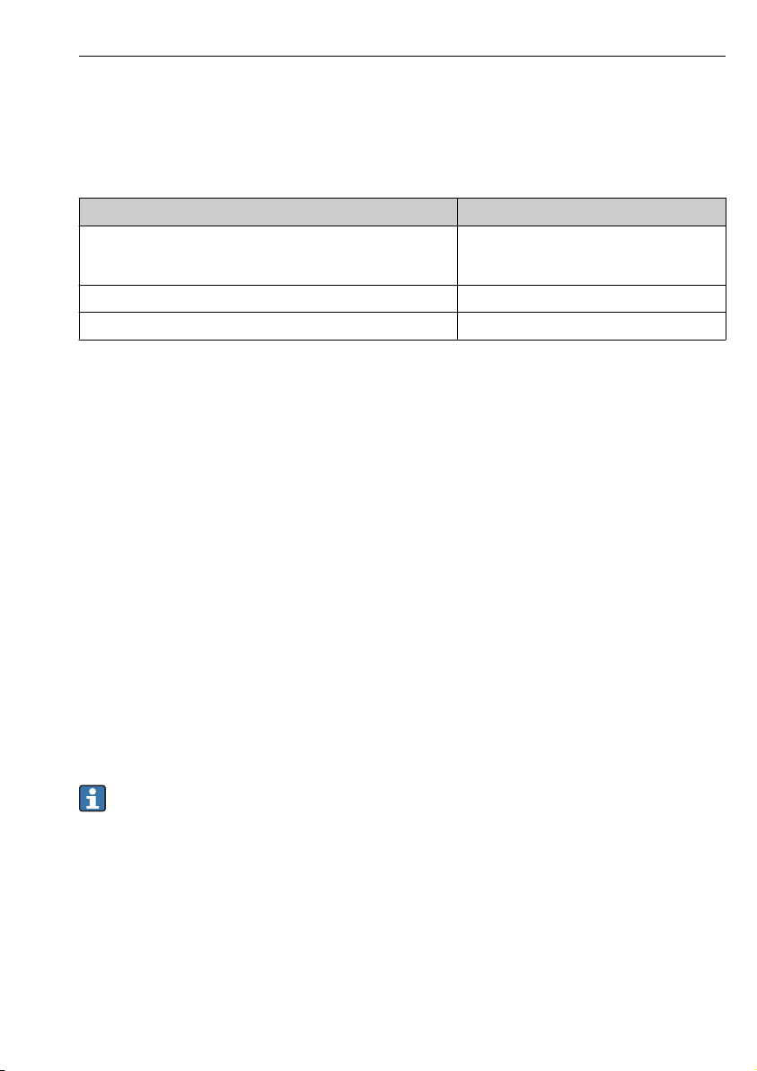
Terminals
Terminal Wire cross section
Signal and power supply
• Spring terminals (NMx8x-xx1...)
• Screw terminals (NMx8x-xx2...)
Ground terminal in the terminal compartment max. 2.5 mm2 (13 AWG)
Ground terminal at the housing max. 4 mm2 (11 AWG)
Power supply line
Standard device cable is sufficient for the power line.
HART communication line
• Standard device cable is sufficient if only the analog signal is used.
• Shielded cable is recommended if using the HART protocol. Observe the grounding concept
of the plant.
Modbus communication line
• Observe the cable conditions from the TIA-485-A, Telecommunications Industry
Association.
• Additional conditions: Use shielded cable.
0.2 to 2.5 mm2 (24 to 13 AWG)
V1 communication line
• Two wire (twisted pair) screened or un-screened cable
• Resistance in one cable: ≤ 120 Ω
• Capacitance between lines: ≤ 0.3 µF
6.2.2 Supply voltage
85 to 264 V
AC
The supply voltage is also indicated on the nameplate.
Endress+Hauser 37
Page 38
Electrical connection Proservo NMS80
6.3 Ensuring the degree of protection
To guarantee the specified degree of protection, carry out the following steps after the
electrical connection:
1. Check that the housing seals are clean and fitted correctly. Dry, clean or replace the
seals if necessary.
2. Tighten all housing screws and screw covers.
3. Firmly tighten the cable glands.
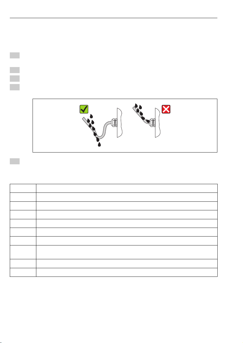
4. To ensure that moisture does not enter the cable entry, route the cable so that it loops
down before the cable entry ("water trap").
A0013960
5. Insert blind plugs appropriate for the safety rating of the device (e.g. Ex d/XP).
6.4 Post-connection check
Are cables or the device undamaged (visual inspection)?
m
Do the cables comply with the requirements?
m
Do the cables have adequate strain relief?
m
Are all cable glands installed, firmly tightened and correctly sealed?
m
Does the supply voltage match the specifications on the transmitter nameplate?
m
Is the terminal assignment correct → 27?
m
If required: Is the protective earth connected correctly ?
m
If supply voltage is present: Is the device ready for operation and do values appear on the display
m
module?
Are all housing covers installed and firmly tightened?
m
Is the securing clamp tightened correctly?
m
38 Endress+Hauser
Page 39
Proservo NMS80 Commissioning
XX XX XXXX X
mm
1
2
7 Commissioning
7.1 Operating methods
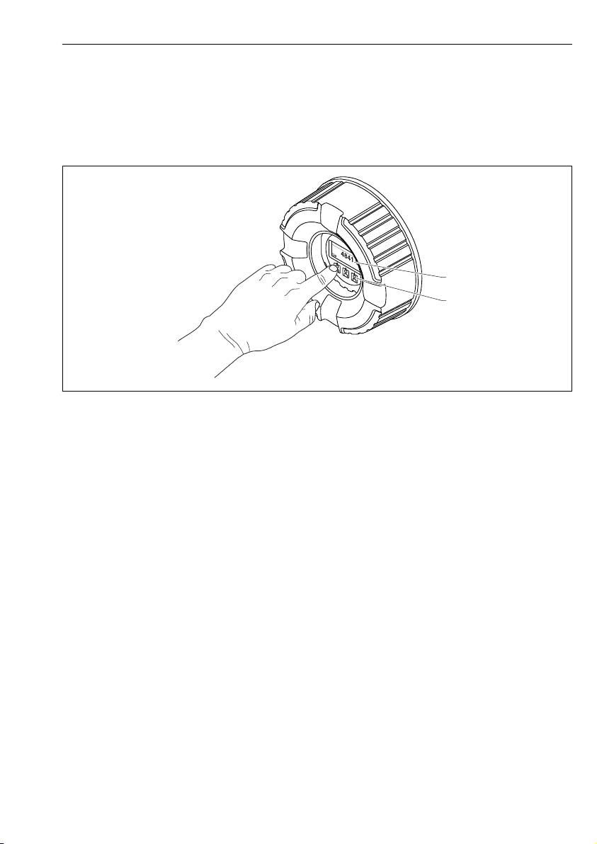
7.1.1 Operation via the local display
A0028345
19 Display and operating elements
1 Liquid crystal display (LCD)
2 Optical keys; can be operated through the cover glass.
Endress+Hauser 39
Page 40
Commissioning Proservo NMS80
X X X X X X XX X
5
2
1
3
mm
4841.00
Level bal.
F
4
Standard view (measured value display)
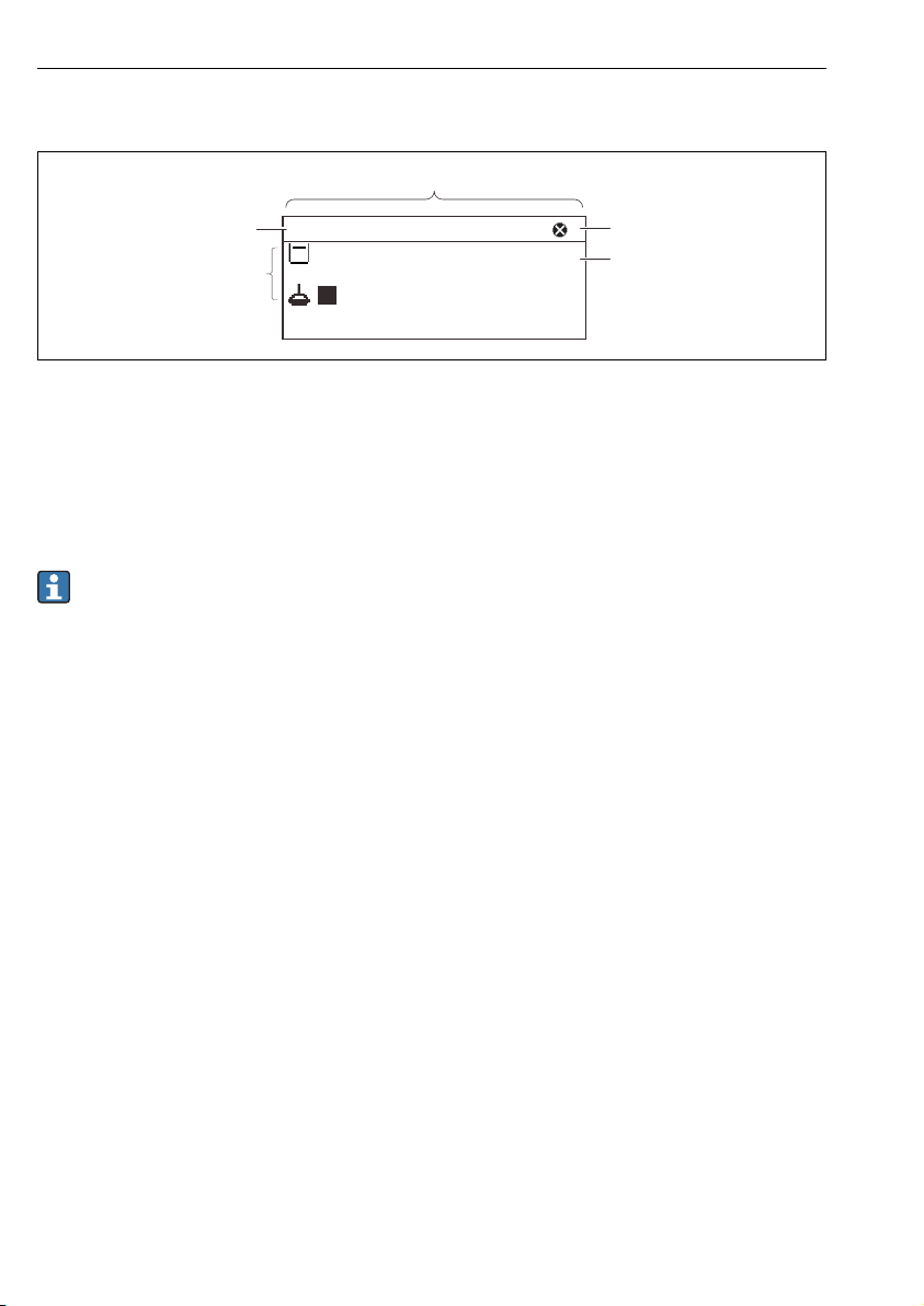
A0028702
20 Typical appearance of the standard view (measured value display)
1 Display module
2 Device tag
3 Status area
4 Display area for measured values
5 Display area for status symbols
For the meaning of the display symbols refer to the Operating Instructions (BA) of the
device.
40 Endress+Hauser
Page 41
Proservo NMS80 Commissioning
3
1
2
/../Setup
00215-1
10,000.00 mm
Empty
Set level
Calibration
CDI
1
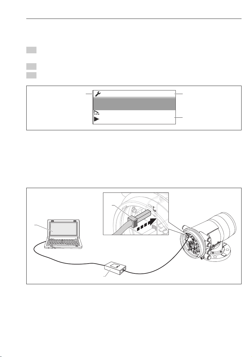
2
Navigation view (operating menu)
To access the operating menu (navigation view), proceed as follows:
1. While in the standard view, press E for at least two seconds.
A context menu appears.
2. Select Keylock off from the context menu and confirm by pressing E.
3. Press E again to access the oprating menu.
A0028347-EN
21 Navigation view
1 Current submenu or wizard
2 Quick access code
3 Display area for navigation
7.1.2 Operation via service interface and FieldCare/DeviceCare
A0030161
22 Operation via service interface
1 Service interface (CDI = Endress+Hauser Common Data Interface)
2 Commubox FXA291
3 Computer with "FieldCare" or "DeviceCare" operating tool and "CDI Communication FXA291" COM DTM
Endress+Hauser 41
Page 42
Commissioning Proservo NMS80
4
13
A
B
C
D
E
F
G
5
H
1
2
14
15
16
17
10
11
12
6
7
8
9
3
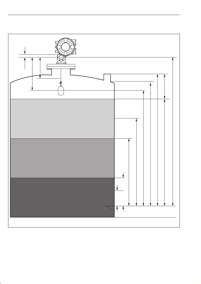
7.2 Terms related to tank measurement
23 Terms concerning NMS8x installation
A Liquid level
B Upper interface
C Lower interface
D Gas phase
E Upper phase
F Middle phase
42 Endress+Hauser
A0026916
Page 43

Proservo NMS80 Commissioning
G Lower phase
H Tank bottom
1 Gauge reference height
2 Empty
3 Datum plate
4 Ullage level
5 Level
6 Tank reference height
7 High stop
8 Displacer position
9 Standby level
10 Upper interface level
11 Lower interface level
12 Low stop
13 Dipping reference
14 Mechanical stop
15 Slow hoist zone
16 Measured distance
17 Reference position
7.3 Setting the display language
This setting is only relevant for operation via the display module. To set the language in
the operating tool, use the language setting functionality of FieldCare or DeviceCare,
respecitvely.
1. While in the standard view, press E. If required, select Keylock off from the context
menu and press E again.
The Language parameter appears.
2. Open the Language parameter and select the display language.
3. Confirm your selection by pressing E.
Endress+Hauser 43
Page 44
Commissioning Proservo NMS80
7.4 Calibration
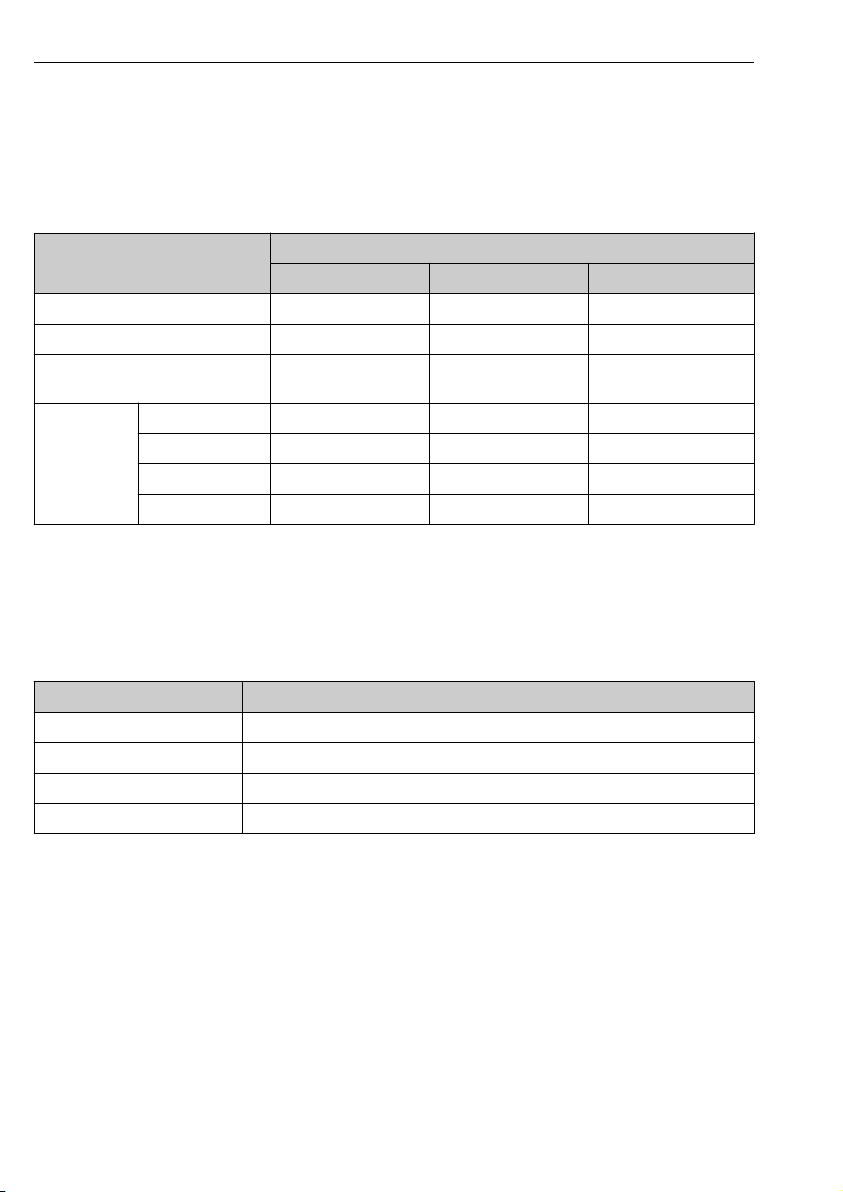
After installing or replacing NMS8x or its parts (sensor module, detector unit, wire drum, or
measuring wire), several calibration steps are required. All calibration steps may not be
required, depending on whether the device is being installed, adjusted, or replaced (see table
below).
Type of installation/replacement Calibration step
Sensor calibration Reference calibration Drum calibration
All-in one Not required Not required Not required
Displacer shipped separately Required Required Required
Displacer installation through
calibration window
Replacement/
maintenance
Drum Required Required Required
Displacer Not required Required Required
Sensor module Not required Required Required
Detector unit Required Required Required
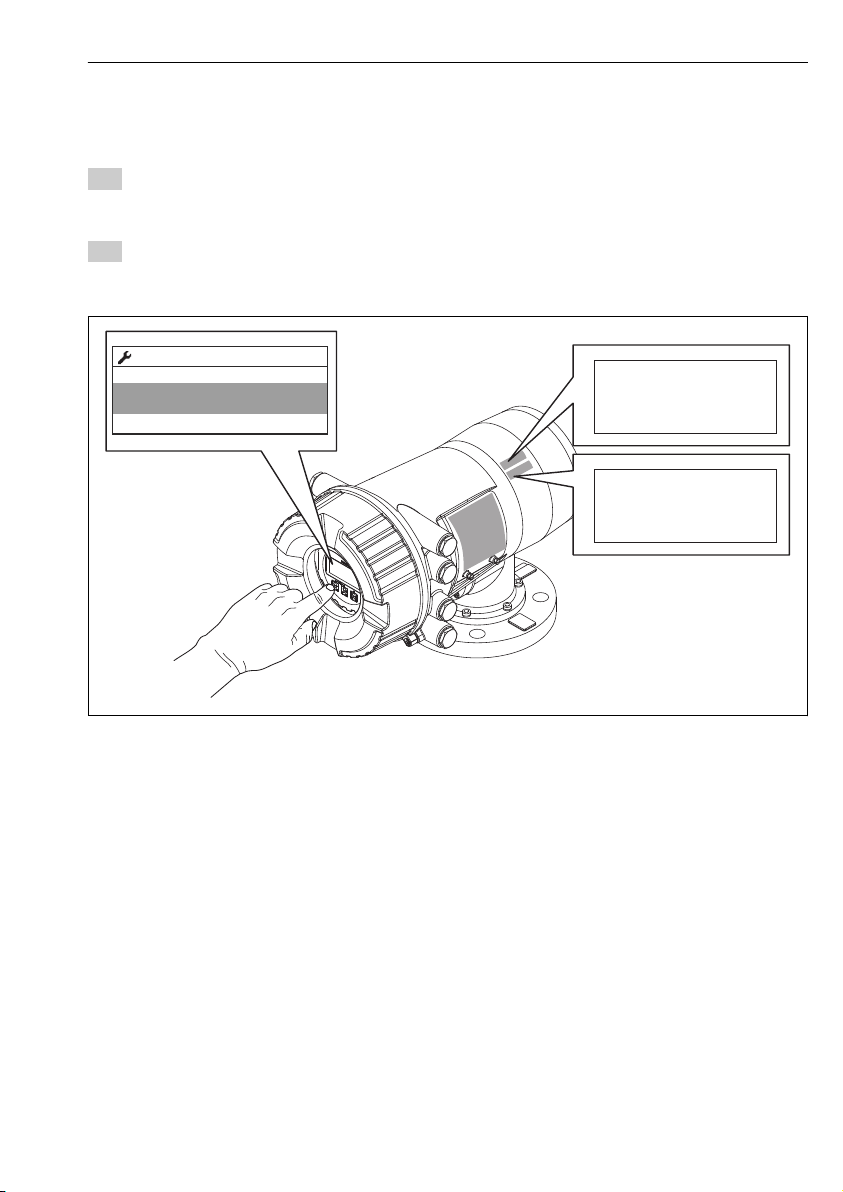
7.4.1 Verification of displacer and wire drum
Prior to installation of NMS8x, confirm that all of the following data of the displacer and the
wire drum on the nameplate match with those programmed into the device.
Required Required Required
Parameters to be confirmed
Parameters Navigate to:
Displacer volume Setup → Advanced setup → Sensor config → Displacer → Displacer volume
Displacer balance volume Setup → Advanced setup → Sensor config → Displacer → Displacer balance volume
Displacer weight Setup → Advanced setup → Sensor config → Displacer → Displacer weight
Drum circumference Setup → Advanced setup → Sensor config → Wiredrum
44 Endress+Hauser
Page 45
Proservo NMS80 Commissioning
316L
50
ml
70.8
ml
141.6
g
256.6
Ø
B
V
D
V
D
m
NMS8
Displacer
712xxxxx
Spare part-no.:
12345678901
Ser.no.:
Ø
0.15
HNBR
mm
302.xxx
m
28
WireDia.
O-Ring
Cir.
Range
NMS8
Wiredrum
712xxxxx
Spare part-no.:
98765432109
Ser.no.:
/../Displacer
08010-1
256.6g
Displacer diamet
Displacer weight
Displacer volume
Data verification
Data verification procedure
1. Check the displacer diameter, weight, volume, and balance volume for the Displacer
diameter parameter, the Displacer weight parameter, the Displacer volume
parameter, and the Displacer balance volume parameter.
2. Check the drum circumference for the Drum circumference parameter.
This completes the data verification procedure.
Endress+Hauser 45
A0030107
Page 46
Commissioning Proservo NMS80
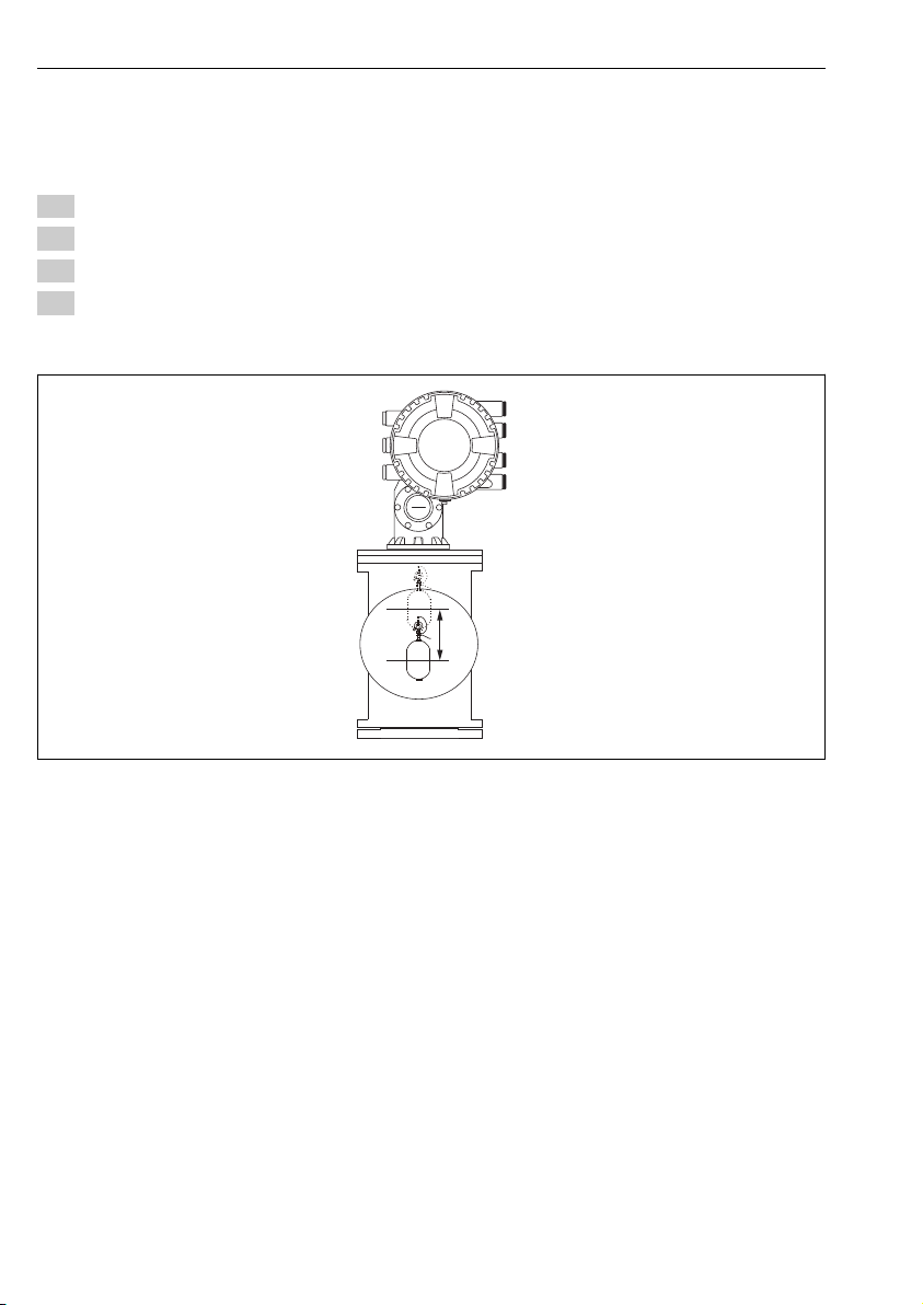
7.4.2 Move displacer
The move displacer operation is optional and can be used to change the current position of the
displacer in order to perform the calibration steps more easily.
1. Navigate to: Setup → Calibration → Move displacer → Move distance
2. Input the relative moving distance for the Move distance parameter.
3. Select the Move down option or the Move up option
4. Select the Yes.
This completes move displacer commands procedure.
A0029119
24 Move displacer
46 Endress+Hauser
Page 47
Proservo NMS80 Commissioning
m
S
m
O2
m
z
m
B
m
O1
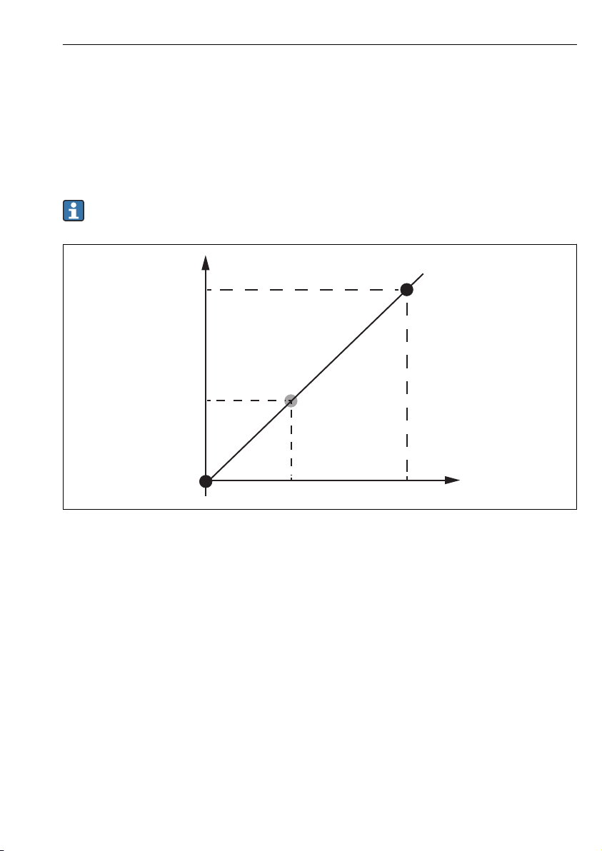
7.4.3 Sensor calibration
Sensor calibration adjusts the weight measurement of the detector unit. The calibration
consists of three steps as follows.
• ADC zero calibration
• ADC offset calibration
• ADC span calibration
For the ADC offset weight calibration, either 0 g or an offset weight (0 to 100 g) can be used.
Using an offset weight other than 0 g is recommended for density measurement.
A0029472
25 Concept of sensor calibration
m Weight of displacer
B Binary value of AD-Converter
mSSpan weight
mo1Offset weight in case of 0 to 100 g (50 g is recommended.)
mo2Offset weight in case of 0 g
mzZero weight
Endress+Hauser 47
Page 48
Commissioning Proservo NMS80
1.
2.
3.
4.
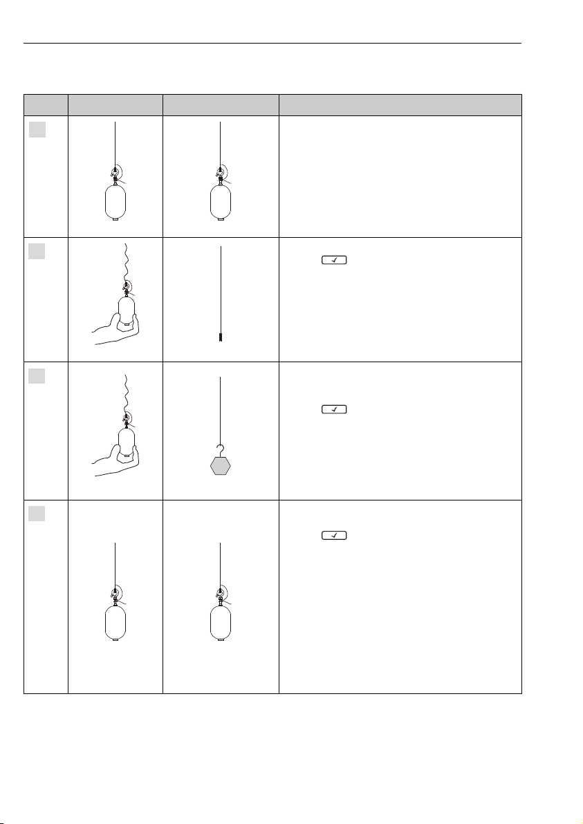
Calibration procedure
Step Using displacer Using offset weight Description
• Navigate to: Setup → Calibration → Sensor calibration
→ Sensor calibration
• Input the offset weight for the Offset weight
parameter used in step 3 (0.0 g in case of using the
displacer only).
• Input the value for the Span weight parameter used
in step 4 (weight of displacer indicated on
nameplate).
A0028000 A0028000
• Hold up or remove the displacer.
• Select for next parameter.
• Measuring zero weight option is shown on the
display.
• Wait until the Zero calibration parameter shows the
Finished option and calibration status shows Idle.
When the displacer is being held up, do not
A0027999
A0027999
A0028000 A0028000
A0028001
A0028002
release it until this step is completed.
• Confirm that the Offset calibration parameter shows
the Place offset weight option.
• Hold up the displacer or attach the offset weight.
• Select for next parameter.
• Measuring offset weight option is shown on the
display.
• Wait until the Offset calibration parameter shows
the Finished option and Calibration status shows Idle.
When the displacer is being held up, do not
release it until this step is completed.
• Release the displacer or mount it on the measuring
ring if an offset weight was used in the previous step.
• Select for next parameter.
• Measuring span weight option is shown on the
display.
• Confirm that the Span calibration parameter shows
the Finished option and Calibration status shows Idle.
• Select the Next option.
• Confirm that the Sensor calibration parameter
shows the Calibration finished option and
Calibration status shows Idle.
This completes sensor calibration procedure.
Do not swing the displacer and keep it in as stable
a position as possible.
48 Endress+Hauser
Page 49
Proservo NMS80 Commissioning
1. 2. 3.
1
R
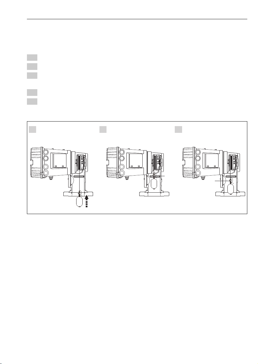
7.4.4 Reference calibration
The reference calibration defines the zero distance position of the displacer from the
mechanical stop.
1. Navigate to: Setup → Calibration → Reference calibration → Reference calibration
2. Select the Start option
3. Check the reference position (e.g. 70 mm (2.76 in)).
The reference position is preset prior to delivery.
4. Confirm that the displacer is correctly attached to the measuring wire.
5. The reference calibration starts automatically.
This completes the reference calibration.
26 Reference calibration sequence
1 Mechanical stop
R Reference position
Endress+Hauser 49
A0030162
Page 50
Commissioning Proservo NMS80
1
2
3
…
50
7.4.5 Drum calibration
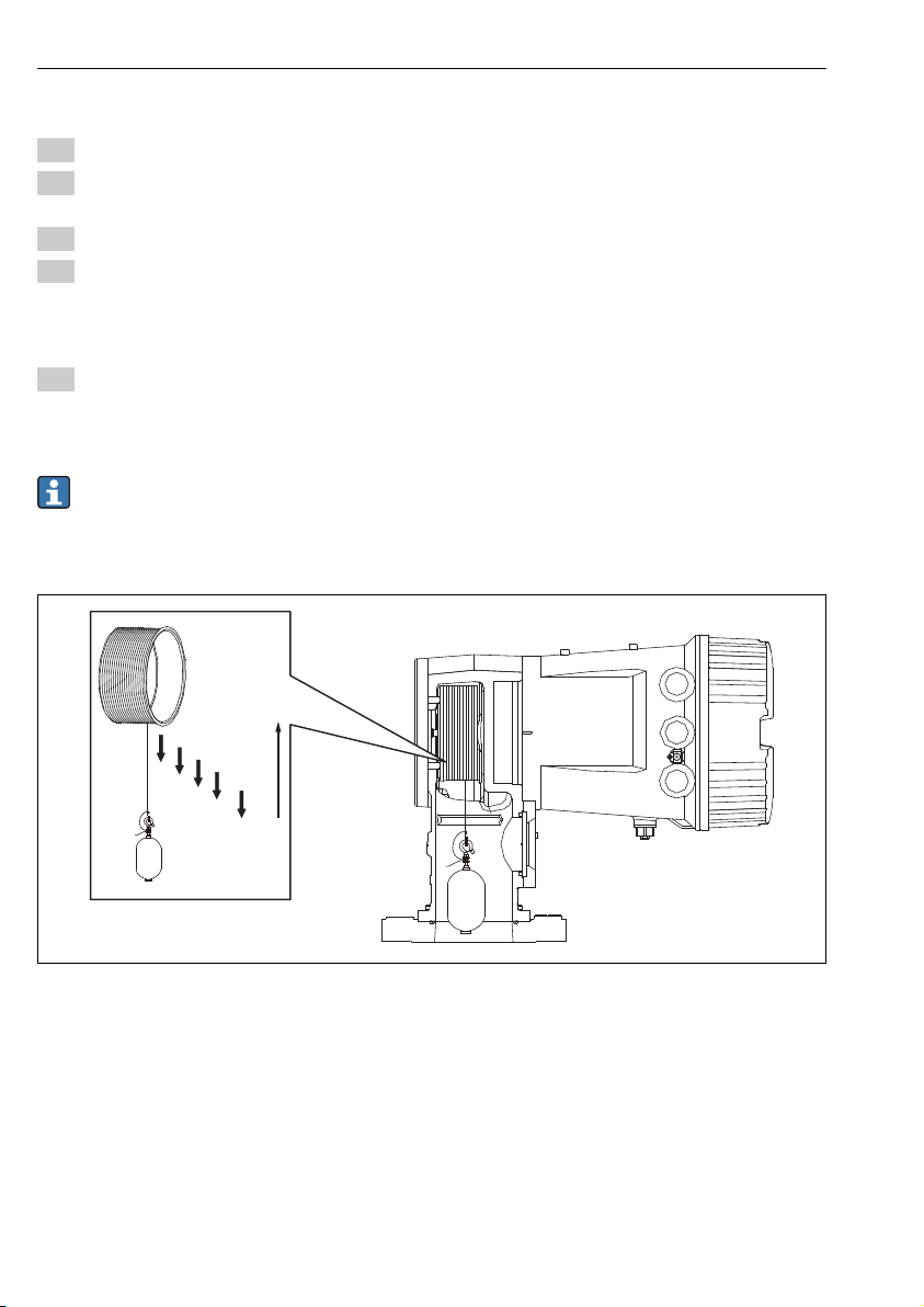
1. Navigate to: Setup → Calibration → Drum calibration → Drum calibration
2. Ensure a distance of 500 mm (19.69 in) or more from the bottom of the displacer to the
liquid level.
3. Confirm that the displacer weight is correct for the Set high weight parameter.
4. Select the Start option.
The drum calibration starts automatically.
The drum calibration records fifty points which will take approximately eleven
minutes.
5. Select the No option as usual for the Make low table parameter.
To make a low table for special applications, select the Yes and use 50 g weight.
This completes drum calibration procedure.
To cancel any calibration, press + simultaneously. If the drum calibration is
canceled while making the new table, the old table remains effective. If making a new
table fails due to an obstruction, NMS8x will not accept the new table and shows an
error message.
A0030163
27 Making drum table
50 Endress+Hauser
Page 51

Proservo NMS80 Commissioning
7.4.6 Commissioning check
This procedure is to confirm that all calibration steps have been completed appropriately.
1. Navigate to: Diagnostics → Device check → Commissioning check → Commissioning
check
2. Select the Start option.
Executing option is shown on the verify drum table.
3. Select the Next option.
4. Confirm that the Commissioning check wizard shows the Finished option.
5. Confirm that the Verify drum table parameter is passed.
This completes the commissioning check procedure.
Endress+Hauser 51
Page 52
Commissioning Proservo NMS80
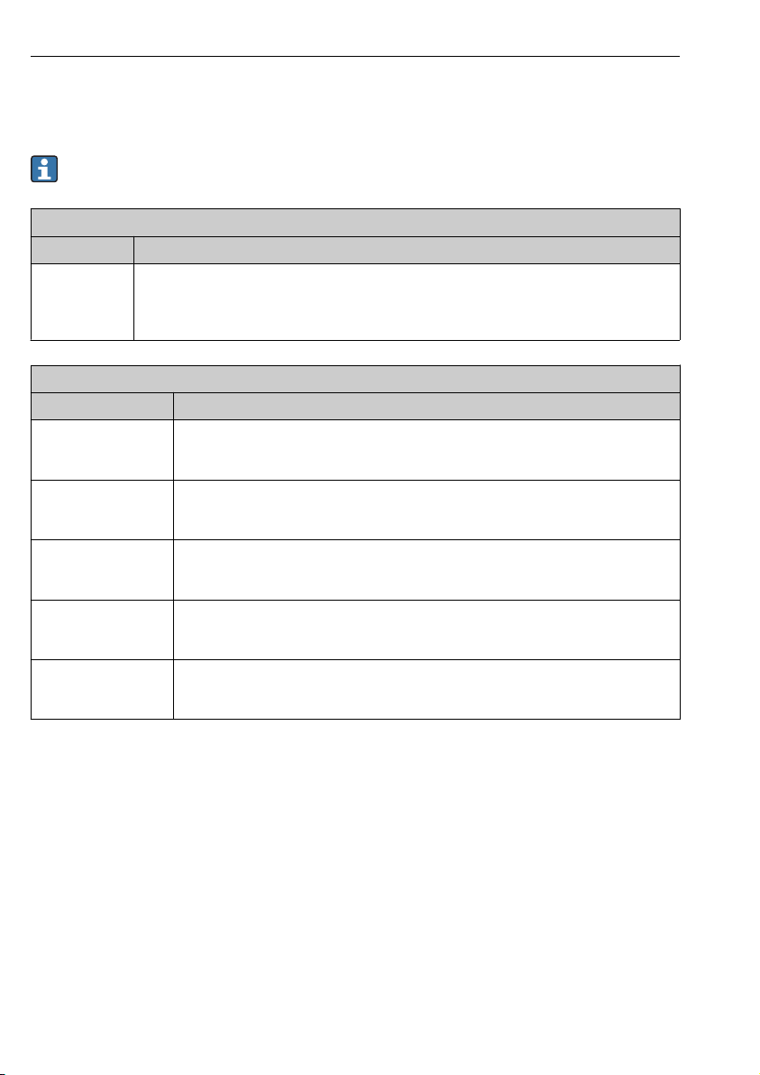
7.5 Configuration of the inputs
7.5.1 Configuration of the HART inputs
HART devices must be configured and given a unique HART address via their own user
interface before they are connected to the Proservo NMS8x.
Submenu: Setup → Advanced setup → Input/output → Analog I/O
Parameter Meaning / Action
Operating mode Select:
• HART master+4..20mA input if only one HART device is connected to this loop. In this case the
4-20mA signal can be used in addition to the HART signal.
• HART master if up to 6 HART devices are connected to this loop.
Submenu: Setup → Advanced setup → Input/output → HART devices → HART Device(s)
Parameter Meaning / Action
Output pressure • If the device measures a pressure: Select which of the HART variables (PV, SV, TV or QV)
Output density • If the device measures a density: Select which of the HART variables (PV, SV, TV or QV)
Output temperature • If the device measures a temperature: Select which of the HART variables (PV, SV, TV or
Output vapor
temperature
Output level • If the device measures a level: Select which of the HART variables (PV, SV, TV or QV)
1) There is a HART Device(s) submenu for each connected HART device.
contains the pressure.
• Otherwise: Keep the factory setting: No value
contains the density.
• Otherwise: Keep the factory setting: No value
QV) contains the temperature.
• Otherwise: Keep the factory setting: No value
• If the device measures the vapor temperature: Select which of the HART variables (PV,
SV, TV or QV) contains the vapor temperature.
• Otherwise: Keep the factory setting: No value
contains the level.
• Otherwise: Keep the factory setting: No value
1)
52 Endress+Hauser
Page 53
Proservo NMS80 Commissioning
4mA
3
20mA
1
4
2
A
I [mA]
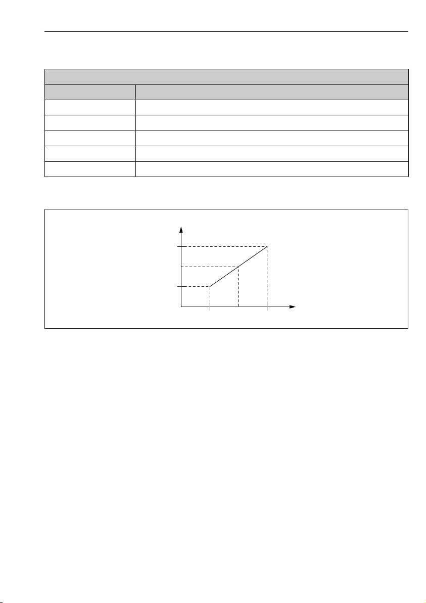
7.5.2 Configuration of the 4-20mA inputs
Submenu: Setup → Advanced setup → Input/output → Analog I/O
Parameter Meaning / Action
Operating mode Select 4..20mA input or HART master+4..20mA input
Analog input source Select which process variable is transmitted by the connected device.
Analog input 0% value Define which value of the process variable corresponds to an input current of 4 mA.
Analog input 100% value Define which value of the process variable corresponds to an input current of 20 mA.
Customer value Check whether the indicated value matches the actual value of the process variable.
1) There is a Analog I/O submenu for each Analog I/O module of the device.
1)
28 Scaling of the 4-20mA input
A Analog input source
1 Analog input 0% value
2 Analog input 100% value
3 Input current
4 Customer value
A0029264
Endress+Hauser 53
Page 54
Commissioning Proservo NMS80
2
1
3
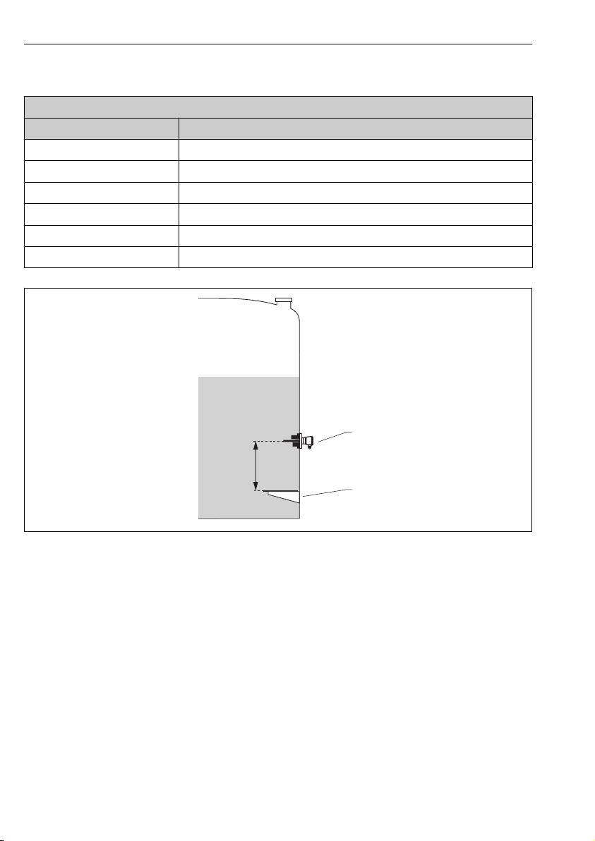
7.5.3 Configuration of a connected RTD
Submenu: Setup → Advanced setup → Input/output → Analog IP
Parameter Meaning / Action
RTD type Specify the type of the connected RTD.
RTD connection type Specify the type of connection of the RTD (2-, 3- or 4-wire).
Input value Check whether the indicated value matches the actual temperature.
Minimum probe temperature Specify the minimum approved temperature of the connected RTD.
Maximum probe temperature Specify the maximum approved temperature of the connected RTD.
Probe position Enter the mounting position of the RTD (measured from the datum plate).
A0029269
1 Datum plate
2 RTD
3 Probe position
54 Endress+Hauser
Page 55
Proservo NMS80 Commissioning
DIO
A
DIO
B
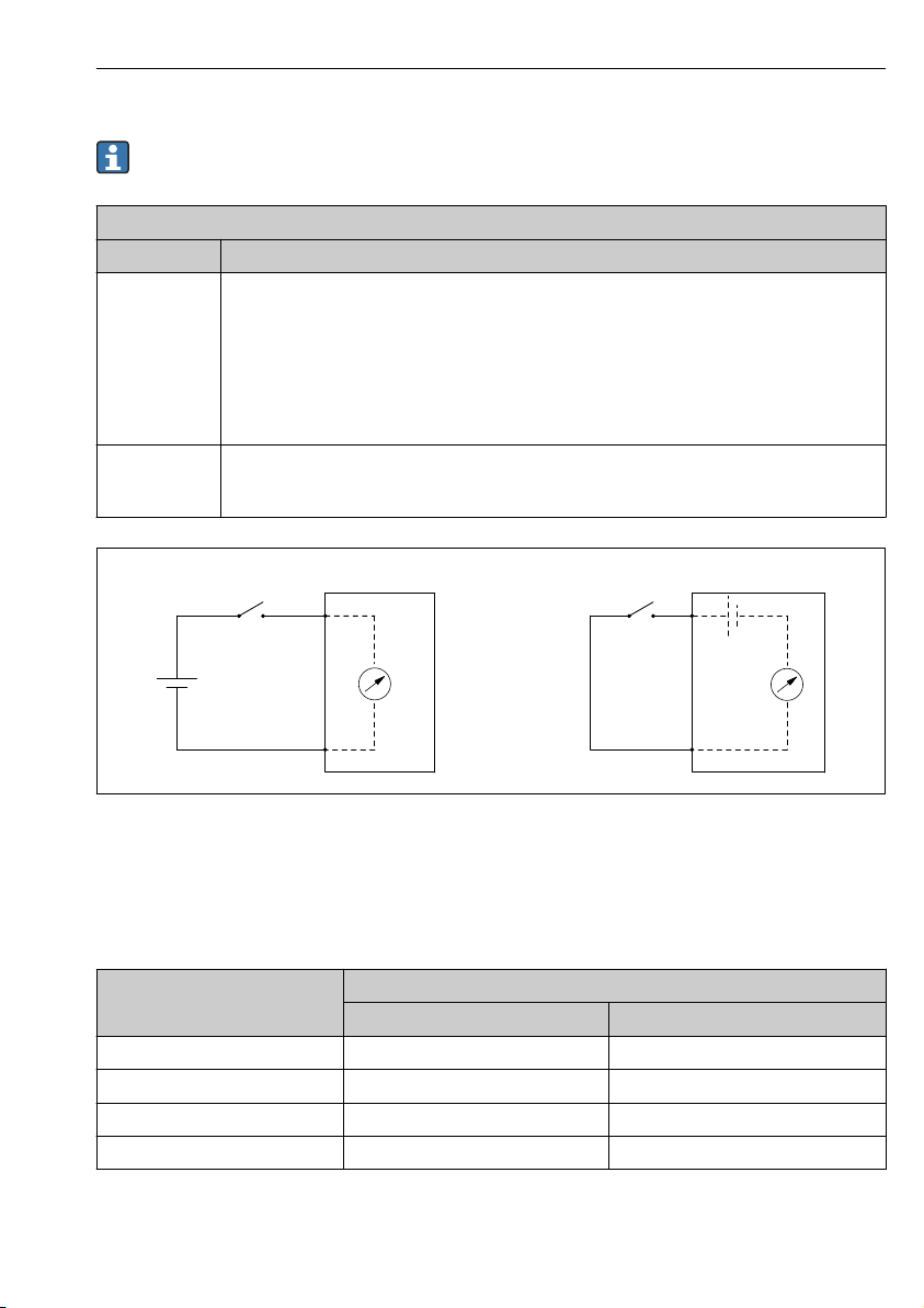
7.5.4 Configuration of the digital inputs
There is a Digital Xx-x submenu for each digital input of the device. "X" designates the
slot in the terminal compartment, "x-x" the terminals within this slot.
Submenu: Setup → Advanced setup → Input/output → Digital Xx-x
Parameter Meaning / Action
Operating mode Select the operating mode (see diagram below).
Contact type Determines how the state of the external switch is mapped to the internal states of the DIO module
• Input passive
The DIO module measures the voltage provided by an external source. Depending on the status
of the external switch, this voltage is 0 (switch open) or exceeds a certain limit voltage (switch
closed). These two states represent the digital signal.
• Input active
The DIO module provides a voltage and uses it to detect whether the external switch is open or
closed.
(see table below). The internal state of the Digital Input can then be transferred to a Digital Output
or can be used to control the measurement.
A0029262
29 Input modes of the Digital I/O module
A "Operating mode" = "Input passive"
B "Operating mode" = "Input active"
Contact types of the digital I/O module
State of the external switch Internal state of the DIO module
Contact type = Normally open Contact type = Normally closed
Open Inactive Active
Closed Active Inactive
During start-up Unknown Unknown
Fault in measurement Error Error
Endress+Hauser 55
Page 56
Commissioning Proservo NMS80
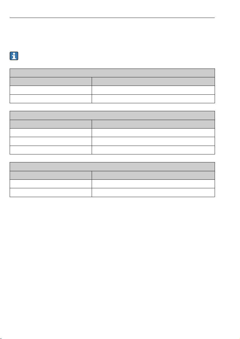
7.6 Linking measured values to tank variables
Measured values must be linked to tank variables before they can be used in the Tank
Gauging application.
Depending on the application not all these parameters will be relevant in a given
situation.
Submenu: Setup → Advanced setup → Application → Tank configuration → Level
Parameter Defines the source of the following tank variableTank variable
Level source Product level
Water level source Bottom water level
Submenu: Setup → Advanced setup → Application → Tank configuration → Temperature
Parameter Defines the source of the following tank variable
Liquid temp source Average or spot temperature of the product
Air temperature source Temperature of the air surrounding the tank
Vapor temp source Temperature of the vapor above the product
Submenu: Setup → Advanced setup → Application → Tank configuration → Pressure
Parameter Defines the source of the following tank variable
P1 (bottom) source Bottom pressure (P1)
P3 (top) source Top pressure (P3)
56 Endress+Hauser
Page 57
Proservo NMS80 Commissioning
A
B
1
2
3
4
5
6
7
8
1
2
3
4
5
6
7
8
9
10
10
7.7 Configuration of the limit evaluation
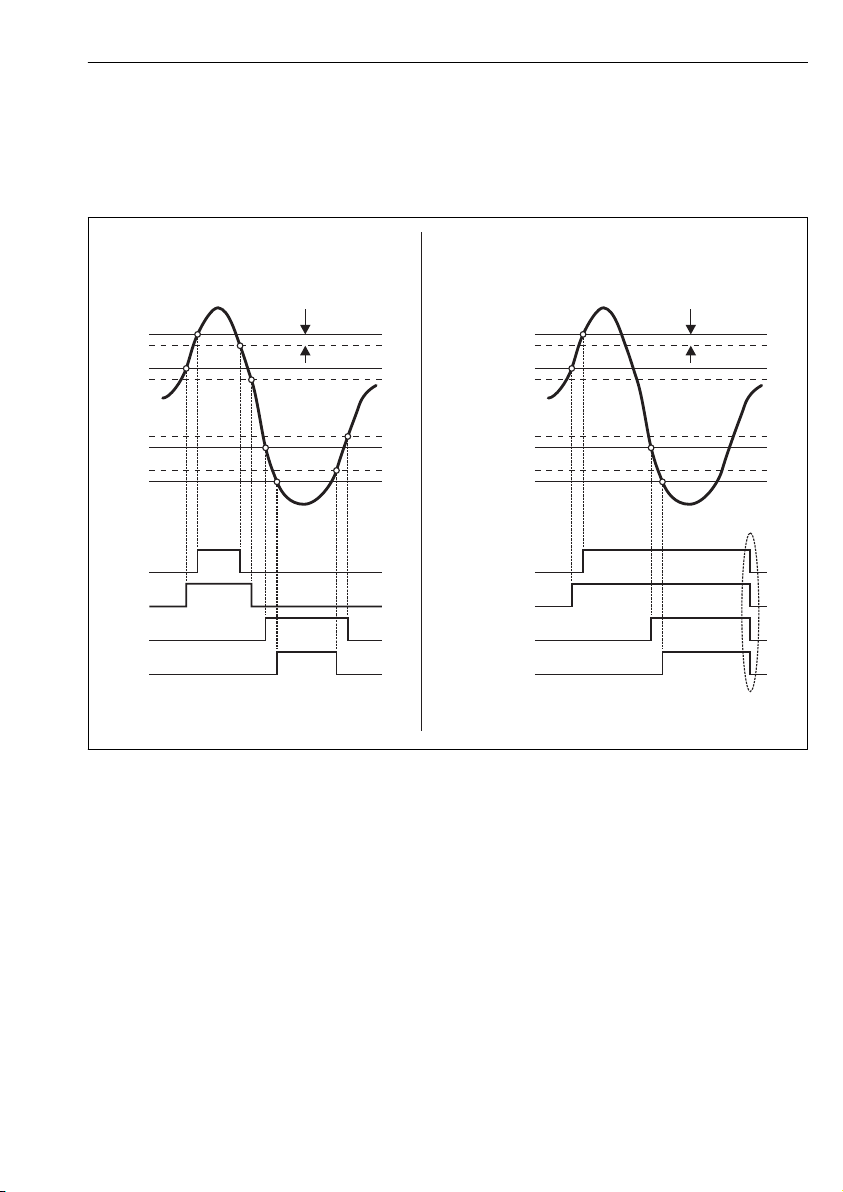
A limit evaluation can be configured for up to 4 tank variables. The limit evaluation generates
an alarm if the value exceeds an upper limit or falls below a lower limit, respectively. The limit
values can be defined by the user.
30 Principle of the limit evaluation
A Alarm mode = On:
B Alarm mode = Latching;
1 HH alarm value
2 H alarm value
3 L alarm value
4 LL alarm value
5 HH alarm
6 H alarm
7 L alarm
8 LL alarm
9 Clear alarm = Yes
10 Hysteresis
Endress+Hauser 57
A0029539
Page 58
Commissioning Proservo NMS80
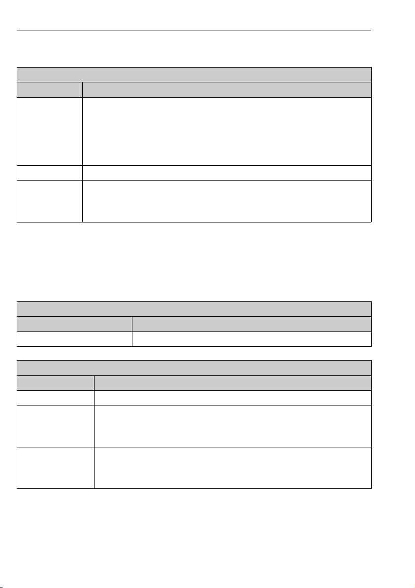
To configure an alarm, assign appropriate values to the following parameters:
Submenu: Setup → Advanced setup → Application → Alarm → Alarm 1 to 4
Parameter Meaning / Action
Alarm mode • Off
Alarm value source Select process variable to be checked for limit violation.
• HH alarm value
• H alarm value
• L alarm value
• LL alarm value
No alarms are generated.
• On
An alarm disappears if the alarm condition is no longer present (taking into consideration the
hysteresis).
• Latching
All alarms remain active until the user selects Clear alarm = Yes.
Assign appropriate limit values (see diagram above).
7.8 Configuration of the signal output
7.8.1 HART output
Each Analog I/O module of the device can be configured as a HART output. To do so, assign
appropriate values to the following parameters:
Setup → Advanced setup → Input/output → Analog I/O
Parameter Meaning / Action
Operating mode Select HART slave +4..20mA output.
Setup → Advanced setup → Communication → HART output → Configuration
Parameter Meaning / Action
System polling address Set the HART communication address of the device.
• Assign PV
• Assign SV
• Assign TV
• Assign QV
• 0 % value
• 100 % value
58 Endress+Hauser
Select which tank variables are to be transmitted by the four HART variables.
The Primary Variable (PV) is not only transmitted by the HART signal but at the same time
by the output current.
These parameters define which value of the Primary Variable (PV) corresponds to an output
current of 4 mA (0 %) or 20 mA (100 %), respectively.
Page 59
Proservo NMS80 Commissioning
7.8.2 Analog output (4...20mA)
Each Analog I/O module of the device can be configured as 4...20mA analog output. To do so,
assign appropriate values to the following parameters:
Setup → Advanced setup → Input/output → Analog I/O
Parameter Meaning / Action
Operating mode Select 4..20mA output.
Analog input source Select which tank variable is transmitted via the analog output.
Analog input 0% value Specify which value of the tank variable corresponds to an output current of 4 mA.
Analog input 100% value Specify which value of the tank variable corresponds to an output current of 20 mA.
7.8.3 Modbus
Depending on the order code the device may have up to two Modbus communication
interfaces. These are configured in the following submenus:
• Setup → Advanced setup → Communication → Communication interface 1 to 2
→ Configuration
• Setup → Advanced setup → Communication → Communication interface 1 to 2 → Integer
conversion
7.8.4 V1
Depending on the order code the device may have one V1 communication interface. It is
configured in the following submenus:
• Setup → Advanced setup → Communication → Communication interface 1 → Configuration
• Setup → Advanced setup → Communication → Communication interface 1 → V1 input
selector
Endress+Hauser 59
Page 60

*71320492*
71320492
www.addresses.endress.com
 Loading...