

Page 1
TI 006N/08/en/04.09
Software Ver. 4.27C
Technical Information
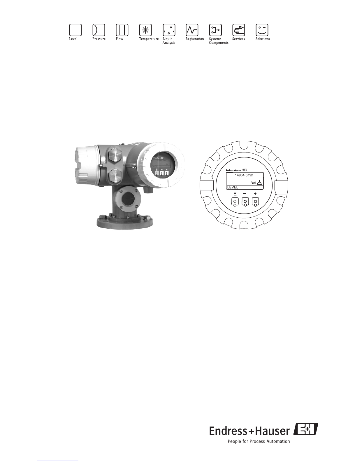
Proservo NMS 5/7 series
Intelligent tank gauge with high accuracy performance
Liquid level, I/F, Density & Density Profile
Application
The Proservo NMS 5/7 series of intelligent tank gauges is
designed for high accuracy liquid level measurement in
storage and process applications.
They fulfill the exact demands of tank inventory
management, loss control, total cost saving and safe
operation.
Typical areas of application include:
• Oil (fuels)
• LPG/LNG
• Chemicals
• Water / chemical interface measurement
• Foods, Liquid Food
Tank mounted intelligence makes the Proservo NMS 5/7
series ideal for single or multi-task installation, converting a
wide range of measurement functions including:
• Liquid level
• Interface level
• Spot density
• Density profile
• Tank bottom
• Water dip
Features and benefits
• Measures liquid to an accuracy of +/- 0.7 mm
• Measures two clear interface levels and specific gravity of
up to three liquid phases
• Profiling of Iiquid density throughout the tank (Tank
profile) and upper layer (I/F profile)
• Latest microtechnology keeps the design simple,
lightweight and compact
• Wetted parts are completely separated from the
electronic circuit
• Tank top mounting with 3” flange weighing only 12 kg
(aluminum version)
• Wide range of output signals including V1, RS 485,
WM550, M/S, Enraf BPM and HART® protocol
• Material and pressure rating of the wetted parts can be
selected according to the application.
• Suitable for atmospheric and high pressure applications
up to 25 bar
• Maintenance prediction of the instrument
• Direct connection of spot or average temperature probes
• Easy to program using the E+H matrix system
• Robust IP67 housing
• Proactive safety diagnostics output to display and System
Operators (patent pending)
Page 2

ProdName
2 Endress+ Hauser
Table of Contents
Function and system design . . . . . . . . . . . . . . . . . . . . . . . . . . 3
Measuring System . . . . . . . . . . . . . . . . . . . . . . . . . . . . . . . . . . . 3
System Configuration . . . . . . . . . . . . . . . . . . . . . . . . . . . . . . . . .4
Major Application . . . . . . . . . . . . . . . . . . . . . . . . . . . . . . . . . . . .4
Operating Principle . . . . . . . . . . . . . . . . . . . . . . . . . . . . . . . . . . .5
Typical Tank installation . . . . . . . . . . . . . . . . . . . . . . . . . . . . . . .6
Measurement terminology . . . . . . . . . . . . . . . . . . . . . . . . . . . . .7
Input . . . . . . . . . . . . . . . . . . . . . . . . . . . . . . . . . . . . . . . . . . . 8
Input for local devices . . . . . . . . . . . . . . . . . . . . . . . . . . . . . . . . .8
Output 8
Output parameters based on communication protocol . . . . . . . . .8
RS485 Modbus . . . . . . . . . . . . . . . . . . . . . . . . . . . . . . . . . . . . . .9
Bidirectional serial pulse (V1 protocol) . . . . . . . . . . . . . . . . . . . . .9
HART Protocol . . . . . . . . . . . . . . . . . . . . . . . . . . . . . . . . . . . . . .9
Whessoematic 550 . . . . . . . . . . . . . . . . . . . . . . . . . . . . . . . . . .10
Mark / Space . . . . . . . . . . . . . . . . . . . . . . . . . . . . . . . . . . . . . .10
Enraf Bi Phase Mark (BPM) . . . . . . . . . . . . . . . . . . . . . . . . . . . .10
Analogue output . . . . . . . . . . . . . . . . . . . . . . . . . . . . . . . . . . . .11
Relay . . . . . . . . . . . . . . . . . . . . . . . . . . . . . . . . . . . . . . . . . . . .11
Power supply . . . . . . . . . . . . . . . . . . . . . . . . . . . . . . . . . . . .12
Supply voltage . . . . . . . . . . . . . . . . . . . . . . . . . . . . . . . . . . . . .12
Power consumption . . . . . . . . . . . . . . . . . . . . . . . . . . . . . . . . .12
Safe electrical isolation . . . . . . . . . . . . . . . . . . . . . . . . . . . . . . .12
Electrical connection . . . . . . . . . . . . . . . . . . . . . . . . . . . . . . 13
Electrical for Primary output V1Serial Pulse
Modbus RS 485 HART Enraf BPM . . . . . . . . . . . . . . . . . . . . . .13
Electrical for Primary output WM 550 . . . . . . . . . . . . . . . . . . . .14
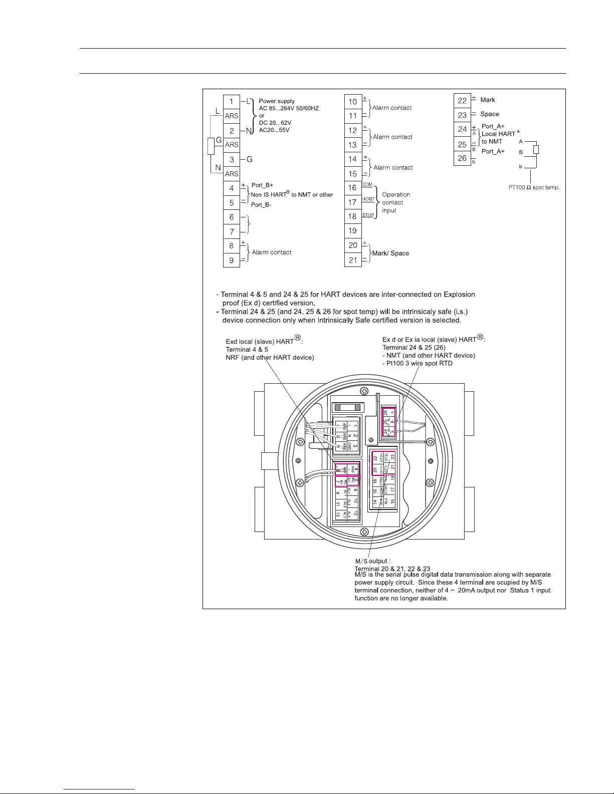
Electric for Primary output M/S . . . . . . . . . . . . . . . . . . . . . . . .15
Bus Installation . . . . . . . . . . . . . . . . . . . . . . . . . . . . . . . . . .16
Rack Bus & Modbus (RS485 Output) . . . . . . . . . . . . . . . . . . . . .16
Sakura V1 Serial Pulse Ouput . . . . . . . . . . . . . . . . . . . . . . . . . .16
Enraf Bi Phase Mark Output . . . . . . . . . . . . . . . . . . . . . . . . . . .17
HART Output . . . . . . . . . . . . . . . . . . . . . . . . . . . . . . . . . . . . . .17
Whessoematic 550 (WM 550) Output . . . . . . . . . . . . . . . . . . .17
Varec Mark Space (M/S) Output . . . . . . . . . . . . . . . . . . . . . . . .18
Performance characteristics . . . . . . . . . . . . . . . . . . . . . . . . .19
Accuracy . . . . . . . . . . . . . . . . . . . . . . . . . . . . . . . . . . . . . . . . .19
Compensation . . . . . . . . . . . . . . . . . . . . . . . . . . . . . . . . . . . . .19
Ambient condition . . . . . . . . . . . . . . . . . . . . . . . . . . . . . . . . 19
Ambient temperature . . . . . . . . . . . . . . . . . . . . . . . . . . . . . . . .19
Liquid temperature . . . . . . . . . . . . . . . . . . . . . . . . . . . . . . . . . .19
Protection . . . . . . . . . . . . . . . . . . . . . . . . . . . . . . . . . . . . . . . . .19
Mechanical construction . . . . . . . . . . . . . . . . . . . . . . . . . . .20
Design, dimensions Housing materials of Construction . . . . . . . 20
Weight . . . . . . . . . . . . . . . . . . . . . . . . . . . . . . . . . . . . . . . . . . 20
Flange type . . . . . . . . . . . . . . . . . . . . . . . . . . . . . . . . . . . . . . . 20
Operating presse. . . . . . . . . . . . . . . . . . . . . . . . . . . . . . . . . . . . 20
Measuring range . . . . . . . . . . . . . . . . . . . . . . . . . . . . . . . . . . . 20
Measuring wire . . . . . . . . . . . . . . . . . . . . . . . . . . . . . . . . . . . . 20
Displacer . . . . . . . . . . . . . . . . . . . . . . . . . . . . . . . . . . . . . . . . . 21
Cable entry . . . . . . . . . . . . . . . . . . . . . . . . . . . . . . . . . . . . . . . 21
Human interface . . . . . . . . . . . . . . . . . . . . . . . . . . . . . . . . .22
Operating concept . . . . . . . . . . . . . . . . . . . . . . . . . . . . . . . . . . 22
Display(LCD) . . . . . . . . . . . . . . . . . . . . . . . . . . . . . . . . . . . . . . 22
Programming . . . . . . . . . . . . . . . . . . . . . . . . . . . . . . . . . . . . . . 22
Memo function . . . . . . . . . . . . . . . . . . . . . . . . . . . . . . . . . . . . 22
Advanced Maintenance . . . . . . . . . . . . . . . . . . . . . . . . . . . .23
Maintenance Prediction . . . . . . . . . . . . . . . . . . . . . . . . . . . . . . 23
Automatic Displacer Weight Compensation . . . . . . . . . . . . . . . 23
Automatic Compensation of Wire Length . . . . . . . . . . . . . . . . . 23
Maintenance . . . . . . . . . . . . . . . . . . . . . . . . . . . . . . . . . . . . . . 23
Certificates and Approval . . . . . . . . . . . . . . . . . . . . . . . . . . . 24
Ex approvals . . . . . . . . . . . . . . . . . . . . . . . . . . . . . . . . . . . . . . 24
Custoday transfer approvals . . . . . . . . . . . . . . . . . . . . . . . . . . . 24
Overspill protection . . . . . . . . . . . . . . . . . . . . . . . . . . . . . . . . . 24
External standards and guidelines . . . . . . . . . . . . . . . . . . . . . . 24
Ordering information . . . . . . . . . . . . . . . . . . . . . . . . . . . . . .25
Proservo NMS5.. . . . . . . . . . . . . . . . . . . . . . . . . . . . . . . . . . . . 25
Proservo NMS7..(Sanitary version) . . . . . . . . . . . . . . . . . . . . . . 28
Accessories . . . . . . . . . . . . . . . . . . . . . . . . . . . . . . . . . . . . .30
Calibration Chamber . . . . . . . . . . . . . . . . . . . . . . . . . . . . . . . . 30
Power+Control Switch . . . . . . . . . . . . . . . . . . . . . . . . . . . . . . 32
Ball Valve . . . . . . . . . . . . . . . . . . . . . . . . . . . . . . . . . . . . . . . . 33
Reducing Flange . . . . . . . . . . . . . . . . . . . . . . . . . . . . . . . . . . . 35
Supplementary Documentation . . . . . . . . . . . . . . . . . . . . . .36
Technical Information . . . . . . . . . . . . . . . . . . . . . . . . . . . . . . . 36
Operating Manual . . . . . . . . . . . . . . . . . . . . . . . . . . . . . . . . . . 36
Compact Instructions . . . . . . . . . . . . . . . . . . . . . . . . . . . . . . . 36
Safety Instructions . . . . . . . . . . . . . . . . . . . . . . . . . . . . . . . . . . 36
Appendix . . . . . . . . . . . . . . . . . . . . . . . . . . . . . . . . . . . . . . .37
Stainless Steel conversion table . . . . . . . . . . . . . . . . . . . . . . . . 37
Page 3
Proservo
Endress+Hauser 3
Function and system design
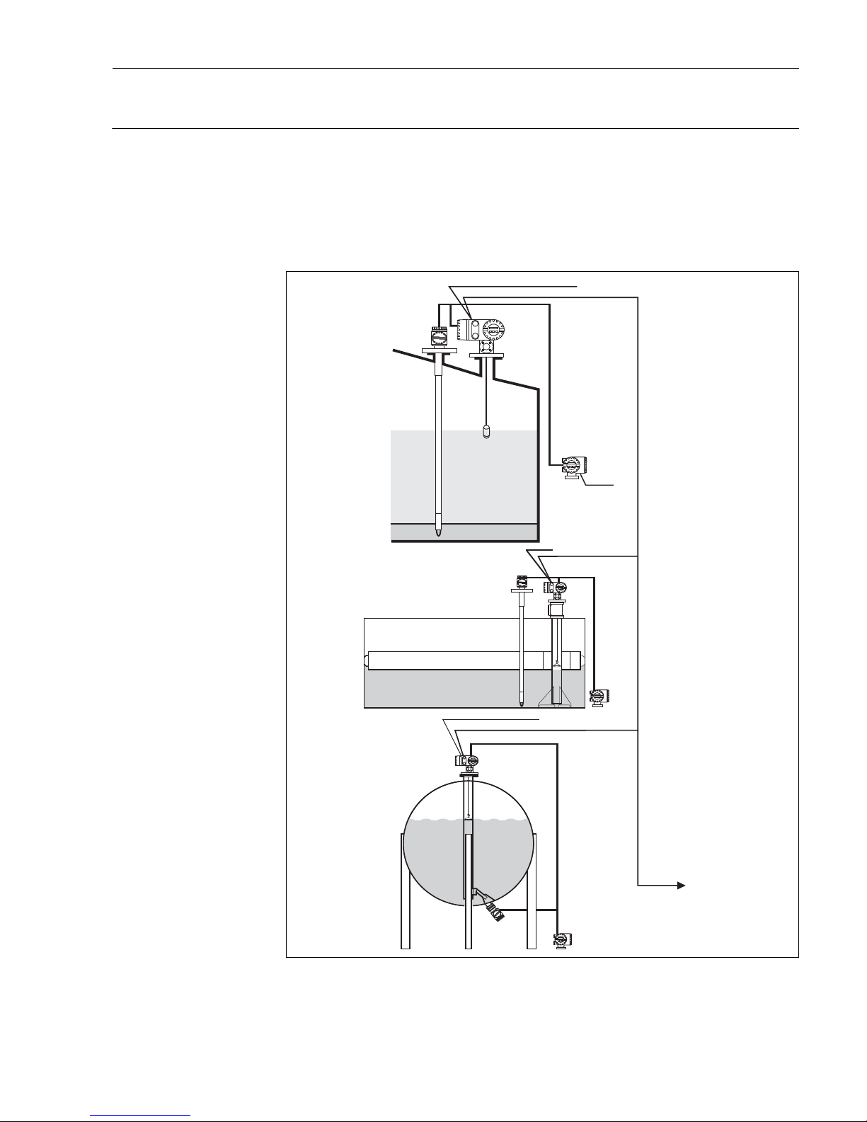
Measuring System The Proservo NMS 5/7 is an intelligent tank gauge for high accuracy liquid level measurement employing the
latest microprocessor technology. As well as level measurement, Proservo NMS 5/7 can determine the interfaces between three liquids, specific gravity of these liquids and tank bottom. To enable accurate volume calculation or simply for indication, Proservo NMS 5/7 will accept an input from either an average temperature
probe NMT 53x series (via twisted pair cables, HART protocol) or via spot temperature element (via 3 wire Pt.
100 RTD signal). Once installed, all calibration and operating functions can be made via the user friendly
Matrix program and touch sensitive keypad. Tank side monitoring and operation can be performed by the
Promonitor NRF 560.
Prothermo
Proservo
Power (AC / DC)
Outputs
HART
Promonitor
Level
Interface
Density
Water dip
Bottom
Power
(AC / DC)
HART
HART
to a HOST system
in a control room
Temp.
Power (AC / DC)
Power (AC / DC)
Page 4

Proservo
4 Endress+ Hauser
System Configuration • From single tank level measurement to the largest oil refinery application, Proservo is an integral part of tank
farm management solutions. A wide variety of data output protocols is available for seamless integration into
many commonly used systems.
• The primary example is Endress+Hauser’s revolutionary Tankvision, a scalable concept offering local tank
management for up to 225 tanks via Modbus, V1 or Whessomatic 550 protocols. Collected data is available
to DCS and other plant management systems via a Host Link.
• Other examples include Endress+Hauser’s legacy systems such as MDP V1 Interface, FuelsManager, Tank
Computers NRM571 and NRS57.
• Output protocols
•Modbus, RS485 or current loop
•V1 serial pulse
•Whessomatic 550
•HART
•Mark/Space
•
Enraf BPM
Proservo NMS 5/7 system configuration Serial pulse output
Major Application The number of measuring functions and output options as well as the lightweight compact design enables
Proservo NMS 5/7 to be installed in a wide range of applications at minimal cost.
Petroleum Industry
From the production of oil to storage at an oil depot, there is a need to measure and manage a wide variety of
products. A remote tank gauging and inventory management system combined with Proservo NMS 5 and a
receiving computer is an ideal way to measure and control the contents of the tanks.
Chemical Industry
For this industry, a wide choice of materials is available for the construction of the wetted parts, to ensure
chemical compatibility and long life.
Food Industry
In the brewing and beverage industries, where large volume of water or water-based products are being
handled, it is essential to obtain a precise level measurement to establish low cost production. Proservo NMS
7 can be supplied with a built in CIP nozzle if required.
Power Plant
Fuel oil levels are major applications where precise measurement is required to ensure safe operation.
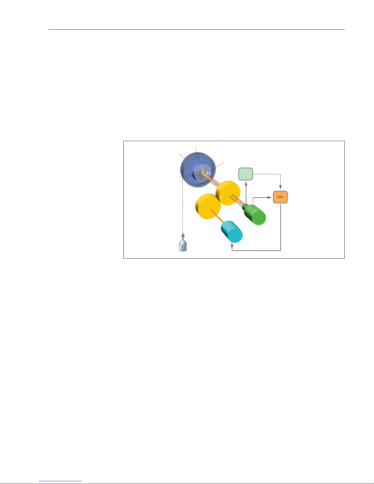
Operating Principle The Proservo NMS 5/7 tank gauging system is based on the principle of displacement measurement.
A small displacer is accurately positioned in the liquid medium using a servo motor. The displacer is suspended
on a measuring wire which is wound onto a finely grooved drum housing within the instrument.
HART
HART
HART
Modbus
SCADA
DCS/PLC
ModbusModbus
SCADA
DCS/PLC
Device Config
Host Link
LAN
TCP/IP
Data Concentrator
Data Scanner
(Field Protcol)
V1, Modbus
Data Scanner
Page 5
Proservo
Endress+Hauser 5
The drum is driven via coupling magnets which are completely separated by the drum housing. Outer magnets
are connected to the wire drum whilst the inner magnets are connected to the drive motor. As the magnets
turn, its magnetic attraction causes the outer magnets to turn as well, as a result turning the entire drum
assembly. The weight of the displacer on the wire creates a torque on the outer magnets generating the change
of magnetic flux. These changes generated between the drum assembly are detected by a unique
electromagnetic transducer on the inner magnet. The drive motor is actuated to balance the voltage generated
by the variations of magnetic flux to equal the reference voltage defined by the operating command.
When the displacer is lowered and touches the liquid, the weight of the displacer is reduced because of the
buoyant force of the liquid. As a result, the torque in the magnetic coupling is changed and this change is
measured by 5 sets of Hall sensors, (patented) chips which are temperature compensated. The signal, an
indication of the position of the displacer, is sent to the motor control circuit. As the liquid level rises and falls,
the position of the displacer is adjusted by the drive motor. The rotation of the wire drum is precisely evaluated
to determine the level value which is accurate to an outstanding +/- 0.7 mm.
Direct Torque Detection
Wire drum
Outside magnet
Inside magnet
Weight
signal
Weight data
Displacer
position
data
Encoder
Motor drive signal
Motor
Displacer
Measurement
wire
Hall element
Page 6
Proservo
6 Endress+ Hauser
Typical Tank installation
E
-
+
Ball Valve
Reducer
Meas. Wire
Displacer
Still well
Proservo NMS5/7
Prothermo NMT
Measuring wire
Displacer
Still well
B
E
+
Prothermo NMT
Proservo NMS5/7
E
+
Measuring wire
Displacer
Still well
Proservo NMS5
Prothermo NMT
E
+
Measuring wire
Displacer
Proservo NMS5/7
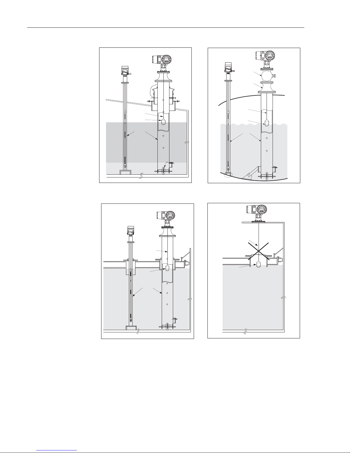
Fixed roof tank with stilling well
High pressure tank with stilling well and ball valve
Floating roof tank and/or covered floating roof tank
Note: When the proservo is installed on Floating
roof tank, be sure to use Stilling Well
Page 7
Proservo
Endress+Hauser 7
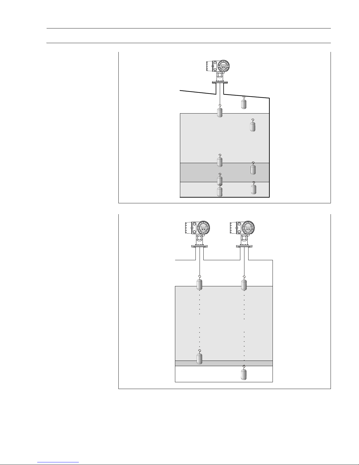
Measurement terminology
NMS 5/7 Proservo with standard level, I/F x 2, Tank bottom and spot density x 3 measurement
Left: Density Profile measurement "I/F (Interface) Profile" measurement range
Right: Density Profile measurement "Tank Profile" measurement range
Level
Upper I/F
Middle I/F
Upper
Density
Middle
Density
Lower
Density
Tank
Bottom
Level
Upper I/F
Tank
floor
Water
Emulsion
Oil
Density measured point
(2 ~ 16 points selecta ble)
between level to upper I/F
Density measured point
(2 ~ 16 po ints selectab le)
Throughout liquid
Tank Profile
True average
density throughout
the tank
I/F Profile
True average
density within
Upper layer
Page 8
Proservo
8 Endress+ Hauser
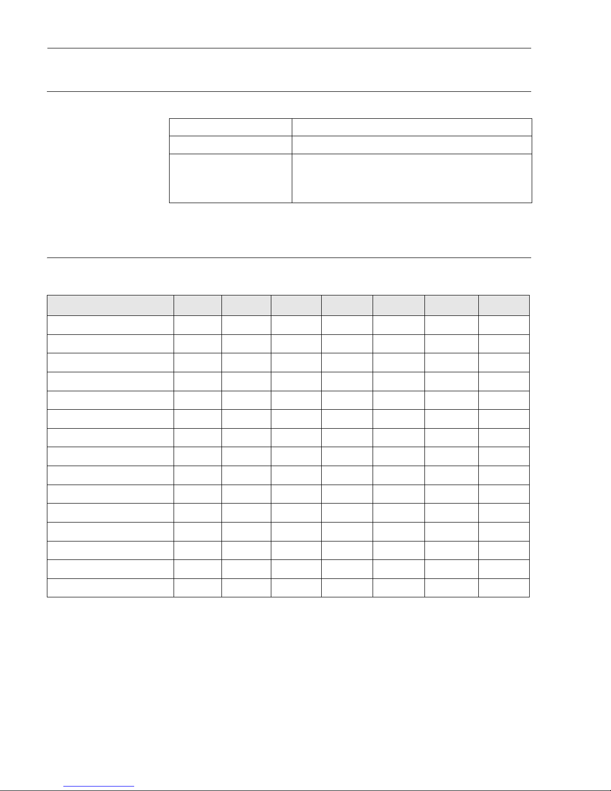
Input
Input for local devices
Output
Output parameters based on
communication protocol
Remarks
1. Upper I/F output value can be either selected from the Proservo’s own displacer measurement or Water
Bottom measured value via the Prothermo NMT 539.
2. A single point density measurement within the upper layer liquid in the tank. The measurement position
is configured to 150mm below the liquid surface at default.
3. A single point density measurement within the middle layer liquid in the tank. The measurement position
is configured to 150mm below the upper interface level at default.
4. A single point density measurement within the lower layer liquid in the tank. The measurement position
is configured to 150mm below the middle interface at default
5. The value of this “Average Density” is based on the calculation after performing the Density Profile operation at the Proservo.
6. All of the selected number of density measured value from 1 ~ 16 points can be transmitted.
Signal Multi drop local HART® protocol max. 4 devices
Power supply DC 24V
Additional units NMT 53x average temperature sensor
NRF 560 field data processor
Other - compatible HART® devices
Spot temperature Pt 100 Ohm ISO standard three wire connection
V1(new) V1 (old) MODBUS HART WM550 ENRAF M/S
Level Yes Yes Yes Yes Yes Yes Yes
Temperature (Product) Yes Yes Yes Yes Yes Yes Yes
Vapor Temperature Yes - Yes Yes Yes - -
Upper I/F (Water Level) *1 Yes - Yes Yes Yes Yes -
Middle I/F Yes - Yes Yes - - -
Upper D e nsity *2 Yes - Yes Yes Yes - -
Middle Densuty*3 Yes - Yes Yes - -
Lower Density*4 Yes - Yes Yes - -
Average Dens ity *5 Yes - Yes - Yes - -
1-16 points Individual Density *6 Yes - Yes - - - -
Multi-Element Temperature Yes - Yes Yes Yes -- -
HART device input (Device 1) Yes - Yes Yes Yes - -
HART device input (Device 2) Yes - Yes Yes Yes - -
Alarm / Discrete V alue Yes Yes Yes Yes Yes Yes -
Protocol Documentation - - KA0002N - KA001N - -
Page 9

Proservo
Endress+Hauser 9
RS485 Modbus
Bidirectional serial pulse
(V1 protocol)
HART Protocol
Module name Commdule RS 485 communication module (~2008),
COM - 5 (2009~)
No. of unit Maximum 10 instruments per loop
Baud rate 600/1,200/ 2,400/ 4,800/ 9,600/ 19,200 bit/s, selectable
Parity Odd, Even, None, selectable
Cable Two wire twisted cable with screening (DGND is connected to the
ground cable)
Topology Serial bus, electrically isolated, tree structure
Transmission distance Maximum 1,200 m including limbs or branches (negligible with
branches under 3 m)
Instrument address Accessed via touch control
Isolation Bus inputs are electrically isolated from the other electronics
Module name COM - 1
No. of units Maximum 10 instruments per loop
Baud rate 3,300 BPS
Cable Two wire (twisted pair) unscreened cable
Topology Serial bus, tree structure
Transmission distance Maximum 6,000 m
Instrument address Accessed via touch control
Isolation Serial communication circuit isolated from other circuits
Module name Commdule HART (2009), COM - 6 (2009~)
No. of units Maximum 15 instruments per loop
Baud rate 1,200 BPS
Cable Two wire, twisted pair screened cable Minimum core φ 0.15
(24AWG)
Transmission distance Maximum 1,200 m
Instrument address Accessed via touch control
Isolation Bus input are electrically isolated from the other electronics
Page 10

Proservo
10 Endress+ Hauser
Whessoematic 550
Mark / Space
Enraf Bi Phase Mark (BPM)
Module name WM550 communication module
No. of units 15 instruments per loop (connected to RTU)
Baud rate 1,200 / 2,400 bit/s
Cable Two wire, twisted cable with screening
Topology 20 mA current loop
Transmission distance Depending on specifications (ask your E+H engineer)
Instrument address Setting by DIP switches on communication board
Isolation Current loop circuit isolated from other circuits
Module name Mark/Space communication module
No. of units Depending on specification (ask to E+H engineer)
Baud rate 1,200 / 2,400 / 4,800 / 9,600 / 19,200 bit/s
Cable Four wire
Topology Serial bus, tree structure
Transmission distance Depending on specifications (ask your E+H engineer)
Instrument address Setting by DIP switches on communication board
Isolation Serial pulse isolated from other circuits
Module name COM - 3
No. of units Maximum 10 instruments per loop
Baud rate 1,200, 2,400 bit/s, selectable
Cable Two wire, twisted cable with screening
Topology Serial bus, electrically isolated, tree structure
Transmission distance Maximum 10 km
Instrument address Accessed via touch control
Isolation Serial communication circuit isolated from other circuits
Page 11

Proservo
Endress+Hauser 11
Analogue output
Relay
Module name I/O - 5
Output 4...20 mA, two channeles freely assignable value
On alarm Switchable +110%, -10% or hold last measured value
Electrical isolation Analogue output isolated from other circuits
Adjustable damping 0 to 99 s
Maximum load 500 ohm
Load effect Negligible
Module name I/O - 3
Version 4 relays with potential free change-over contacts, freely assignable to
measured value
Hysteresis Switch points and switching hysteresis freely adjustable, residual
current fail-safe mode: minimum or maximum, selectable
Switching capacity AD max. 2 A, max. 250 V, max. 62.5 VA
DC max. 2 A, max. 220 V, max. 60 W
For FM / CSA: 5A250VAC, 8A250VAC
Page 12

Proservo
12 Endress+ Hauser
Power supply
Supply voltage High voltage type: 85 ... 264 VAC 50/60 Hz
Low voltage type: 20 ... 60 VDC / 20 ... 55 VAC 50/60Hz
Caution!
Allowable voltage supply is specifically stated depending on each Ex approvals. Refer to the designated
certification
Power consumption Maximum 50 VA, 50W (cos j=0.5)
Safe electrical isolation Between power supply and signal output, CPU, RS 485, relay and other electronics
Page 13
Proservo
Endress+Hauser 13
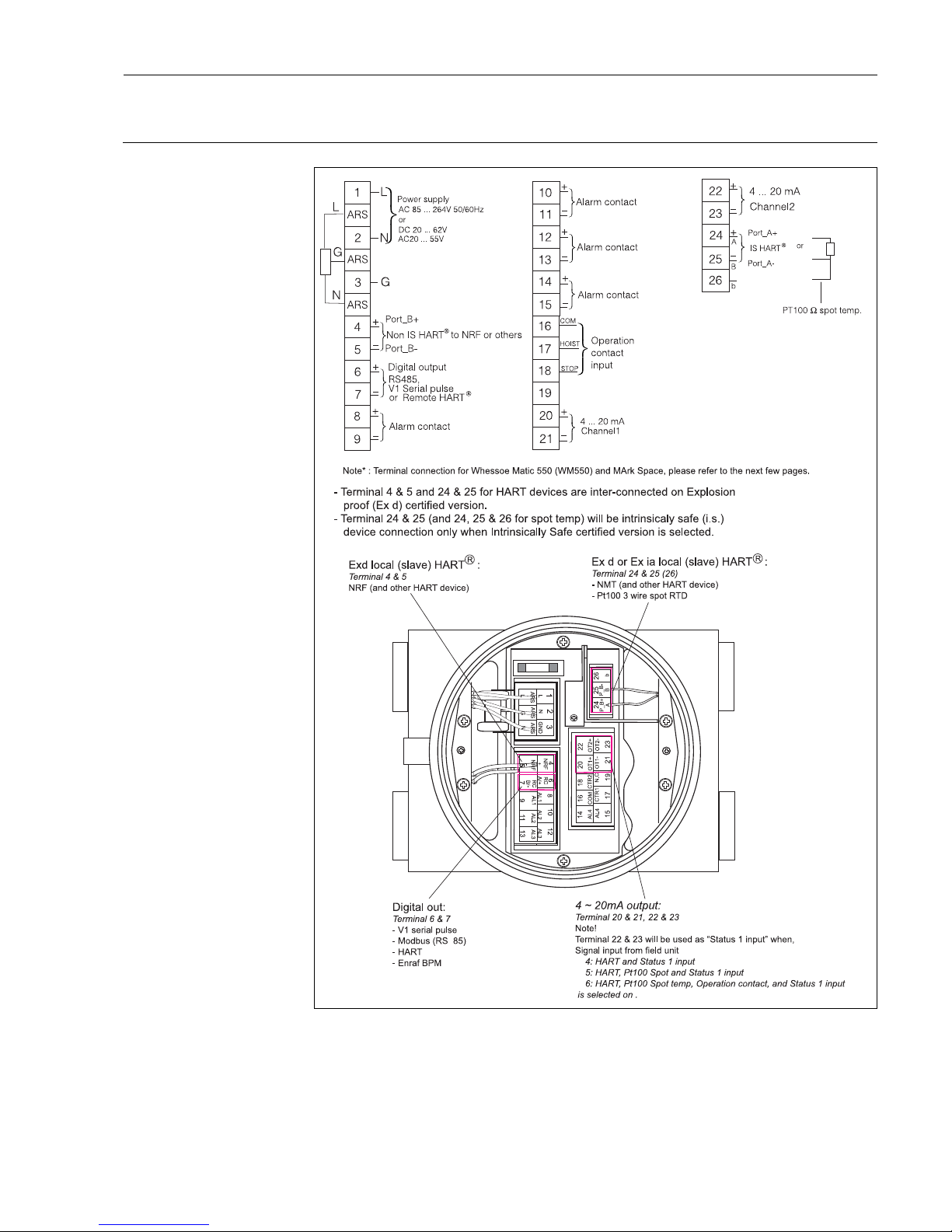
Electrical connection
Electrical for Primary output
V1Serial Pulse
Modbus RS 485
HART
Enraf BPM
4
Page 14
Proservo
14 Endress+ Hauser
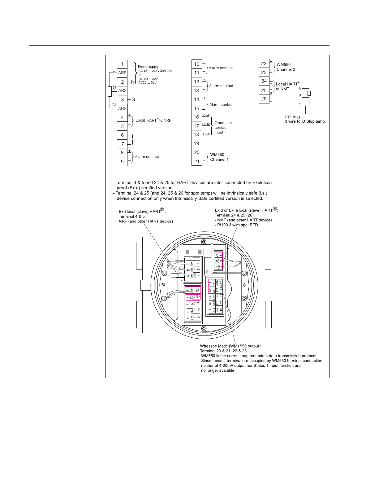
Electrical for Primary output
WM 550
Page 15
Proservo
Endress+Hauser 15
Electric for Primary output
M/S
Page 16

Proservo
16 Endress+ Hauser
Bus Installation
Modbus (RS485 Output) The initial bus voltage is provided by the PC plug-in board or the interface adapter. If an adapter is being used,
then the bus plug must be configured accordingly.
Termination Resistors
It is not necessary to set any termination resistors.
Bus Address
Each transmitter has an individual bus address. Depending on the type of transmitter, this is either defined by
the address switches or by the software of the transmitter itself.
Linking to a Personal Computer
A personal computer is connected using either a RS 485 PC board or an RS 232C / RS 485 external converter
(both with electrical isolation).
Bus Cabling
The bus cabling is galvanically isolated from the transmitter and the PC plug-in board or the interface adapter.
The screening must be grounded and have electrical continuity throughout.
EMC tests indicate the best result when the grounding at both ends and each transmitter is established. If there
is a potential difference in between the grounds,
measurement must be taken to equalize whilst observing a relevant hazardous area.
Bus Topology
When planning the system, attention should be paid to the possible segmentation of the bus according to indi-
vidual plant sections. Suitable topologies are:
• Serial, max. 1200 m
• Tree of total length 1200 m
The bus screening is to be connected at various points.
Sakura V1 Serial Pulse Ouput The bus is connected to a NRM, NRS, RTU8, MDP-III interface, Tankvision or to a receiver. The interface or
receiver must be configured accordingly.
Termination Resistors
It is not necessary to set any termination resistors for serial pulse output.
Bus Address
Each transmitter on a signal loop has an individual bus address. This is defined within the transmitter software.
Bus Cabling
The bus cabling is electrically isolated from the transmitter and from the interface receiver.
Standard communication cable (non-shielded twisted pair cable) can be used for the data transmission.
Bus Topology
The suitable topologies for the serial pulse output are:
Serial max. 6000 m (Sakura V1)
Tree of total length 6000 m. (Sakura V1)
Page 17

Proservo
Endress+Hauser 17
Data transmission & Operation
Sakura serial pulse (V1) output is capable to transmit density profile data (both Tank profile & I/F profile
independently), operation command, & parameter setting between NMS 5/7 Proservo and NRM 571 Tank
Computer.
Enraf Bi Phase Mark Output The bus is connected to an Enraf I/F CIU or RTU8 to transmit measured value to upper host system as Entis
(Enraf TG program) or Fuels Manager. These interface must be configured accordingly.
Termination Resistors
It is not necessary to set any termination resistors for serial pulse output.
Bus Address
Each transmitter on a signal loop has an individual bus address. This is defined within the transmitter software.
Bus Cabling
The bus cabling is electrically isolated from the transmitter and from the interface receiver. Standard
communication cable can be used for the data transmission.
Bus Topology
The suitable topologies for Enraf BPM serial pulse output are:
Serial max. resistance: 400 ohm at 3 bus loops or less (10 transmitters per 1bus loop)
Serial max. capacitance: 1 micro F or less
Data transmission & Operation
NMS 5/7 Proservo is capable to transmit following sensory data as well as gauge operation command via Enraf
BPM serial pulse output.
• Data: level, temperature, operation status
• Gauge command: STOP, UP, LEVEL, I/F
HART Output Registered host system via non-I.S. HART port.
Bus Address
Each transmitter on a signal loop has an individual bus address. This is defined within the transmitter software
and / or auxiliary configuration environment such as host system & hand held terminal (HHT).
Bus Cabling
The bus cabling is galvanically isolated from the transmitter and the PC plug-in board or the interface adapter.
The screening must be grounded and have electrical continuity throughout. EMC tests indicate the best result
when the grounding at both ends and each transmitter is established. If there is a potential difference in
between the grounds,
measurement must be taken to equalize whilst observing a relevant hazardous area.
Bus Topology
The suitable topologies are:
Serial max. 1000 m
Tree of total length 1000 m.
Whessoematic 550 (WM 550)
Output
The bus is normally connected to Whessoe 1098, RTU 8 or other upper host system via dual channel (can be
single) WM550 current loop.
Termination Resistors
Admissible termination resistance should be calculated as follow.
R = [Va - {n x (Vb + Vc)}] / 0.02
R = terminal resistance in the system
n = number of transmitter in the system
Va = max. available voltage at receiver
Page 18

Proservo
18 Endress+ Hauser
Vb = voltage drop across transmitter
Vc = voltage drop across receiver
Bus Address
Each transmitter on a signal loop has an individual bus address. This is defined within the transmitter by
mechanical dip switch on com board.
Bus Cabling
The bus cabling is galvanically isolated from the transmitter and the PC plug-in board or the interface adapter.
BS5308 or equivalent 1.5sq.mm screened twisted pairs are recommended for bus cabling.
Bus Topology
The suitable topologies for the WM550 current output are depending on number of transmitter & cable quality
on the loop. Recommended number of transmitter on single loop shall be less than 15 units to achieve the
maximum performance.
Varec Mark Space
(M/S) Output
The bus is normally connected to Interface Unit (IFU), Data acquisition Processor (DAP), RTU 8 or other upper
host system via 4 wire M/S serial bus link.
Termination Resistors
Admissible termination resistance should be calculated as follow.
R = (48 - 33) / {60mA + N (2.0mA)}
R = terminal resistance in the system
N = number of transmitter in the system
48 = supply voltage to receiver
33 = minimum M/S board operation voltage
60mA = required current for system operation
2.0mA = required current per transmitter
Bus Address
Each transmitter on a signal loop has an individual bus address. This is defined within the transmitter by
mechanical dip switch on com board.
Bus Cabling
The bus cabling is galvanically isolated from the transmitter and the PC plug-in board or the interface adapter.
The total length of field wiring shall be determined by calculation of maximum resistance within the system &
required operation current. Once the total length is determined, distance has to be reduced by half because
of current flow in both B+ & B- leads.
Bus Topology
The suitable topologies for the M/S serial pulse output are depending on number of transmitter & cable quality
on the loop.
Page 19

Proservo
Endress+Hauser 19
Performance characteristics
Accuracy
Compensation Wire
Compensation of wire expansion due to temperature and wire weight
Displacer
Automatic compensation of displacer weight
Tank wall
Compensation of depression and distortion
Ambient condition
Ambient temperature -20... +60oC
-40... +60
o
C ( ATEX approval)
Liquid temperature -200... +200oC
Protection IP 67 with closed housing and cable glands of equal protection type.... (ATEX/TIIS)
NEMA 4X...(FM/CSA)
Liquid level +/-0.7 mm for L=10 m, D=1 g/cm
3
with 50 mm displacer
Interface level +/-2.7 mm for L=10m,
ΔD=0.2 g/cm
3
with 50 mm displacer
ΔD=0.1 g/cm
3
difference between densities of 2 liquids
Spot & profile density +/-5kg/m3 or better, (at reference condition)
Tank bottom +/-2.1 mm (independent from liquid condition)
Page 20
Proservo
20 Endress+ Hauser
Mechanical construction
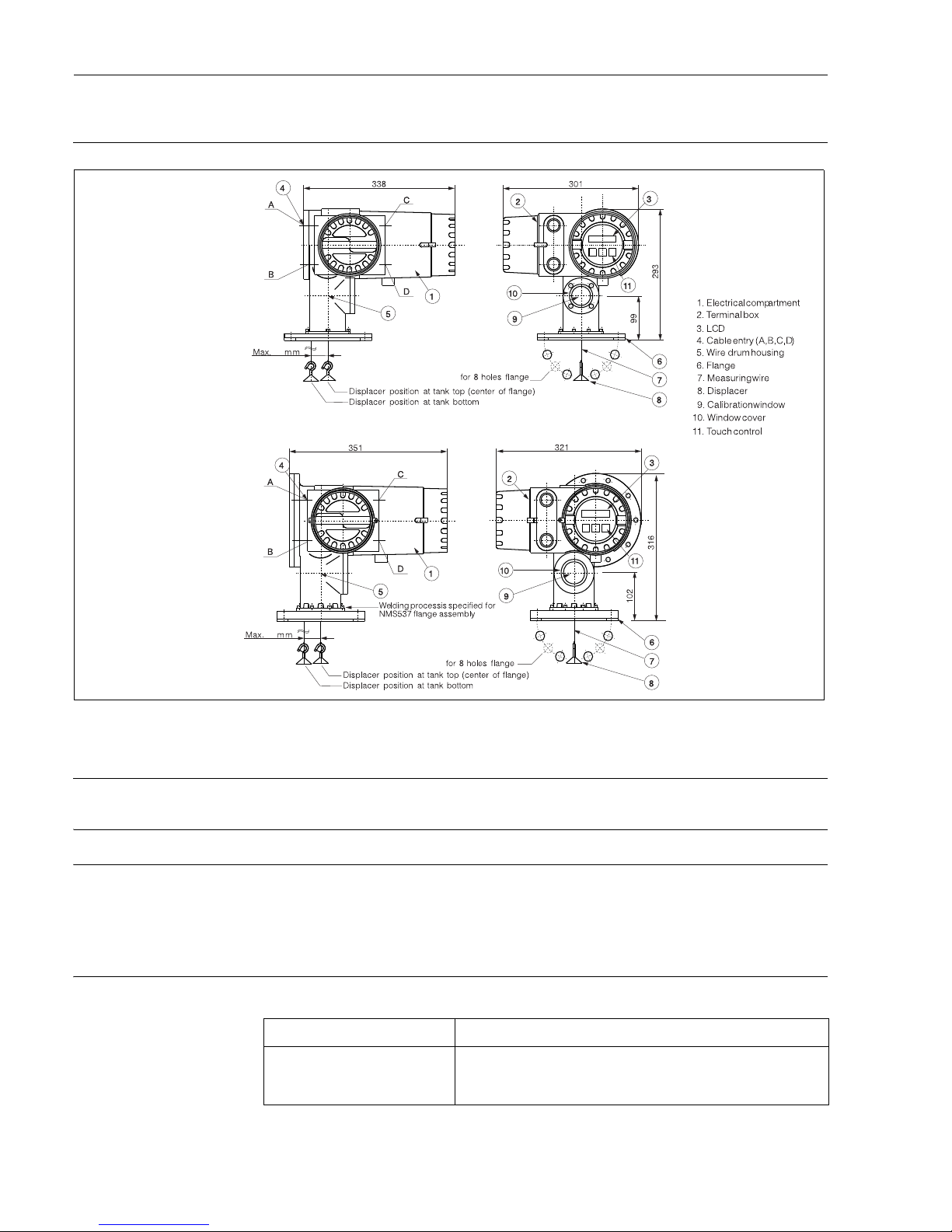
Design, dimensions
Housing materials of
Construction
Electrical compartment : aluminium casting
Drum chamber for NMS 5-1/5-4 : aluminium casting
Drum chamber for NMS 5-2/5-5/5-6 and NMS7 : stainless steel 316 casting
Weight NMS 5-1/5-4 : 12 kg
NMS 5-2/5-5/5-6 and NMS7 : 27 kg
Flange type ANSI, JIS, DIN 3" and 6" (standard) or equivalent. Refer to order code for full selection.
OMeasuring range Level
0 - 36 m (100 m available on request)
Density
0.5000 to 2.0000 g/cm
3
Measuring wire
40
40
NMS5-1, 5-4
NMS5-2,5-5,5-6,NMS7
Range 10 m, 16 m, 28 m, 36 m
Material (standard) Stainless steel 316, 0.15 mm (standard)
Hastelloy C. φ0.2 mm (max. 16 m range)
PFA coated St/St 316L, 0.4 mm (max. 16m range
)
Page 21
Proservo
Endress+Hauser 21
Displacer
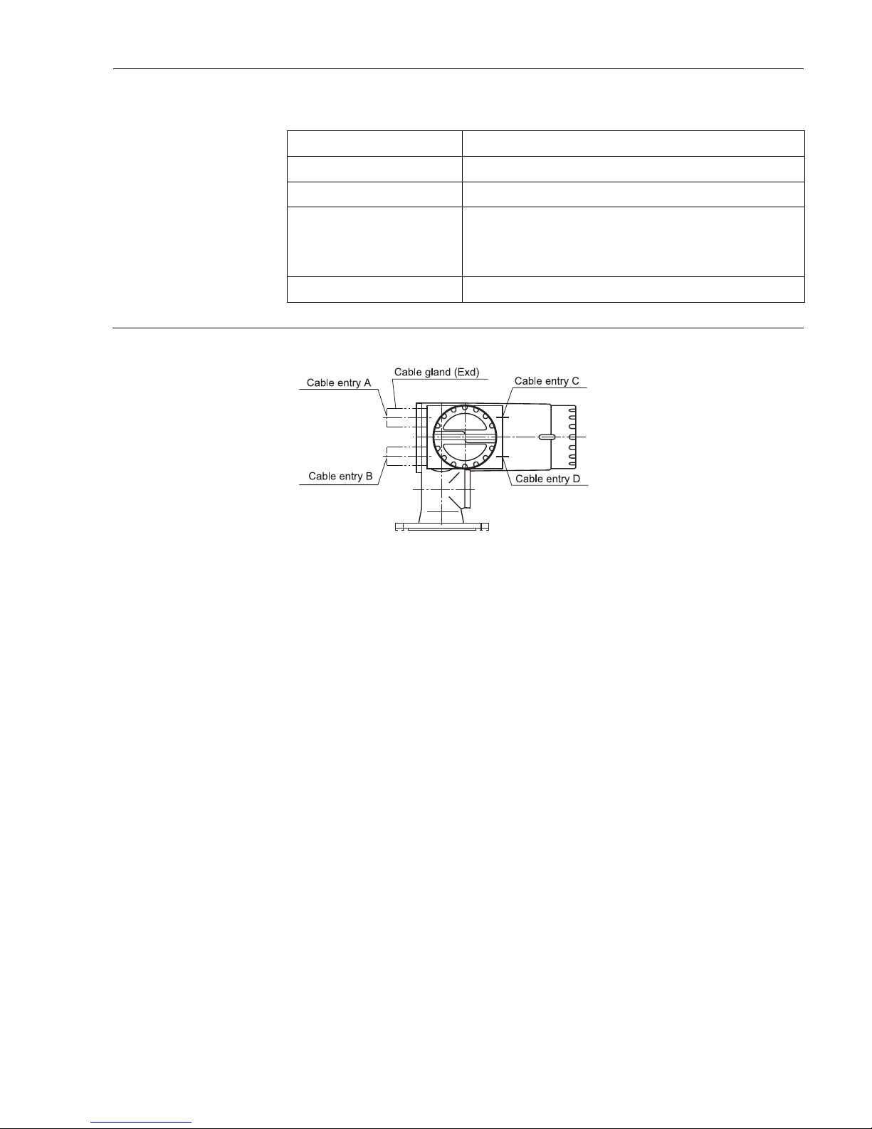
Cable entry
Caution!
All of cable entrys need the cable gland for Explosion-proof (Ex d) or Explosion-proof conduit , even if you
selected a product of IS and Explosion proof (Ex d[ia]).
Diameter 50 mm (Standard), 30...110mm (optional)
Material (standard) Stainless steel 316
Material (optional) Hastelloy C, PTFE
Horizontal movement 10, 16, 28 m (AISI316) :1.23 mm / m with standard 0.15mm wire
36 m (AISI316): 1.1 mm / m with standard 0.15mm wire
10, 16 m (AISI316): 2.17mm /m with PFA covered wire
10, 16 m (Alloy C): 1.73mm/m
Traveling speed 0...2500 mm / min...maxmum
Page 22
Proservo
22 Endress+ Hauser
Human interface
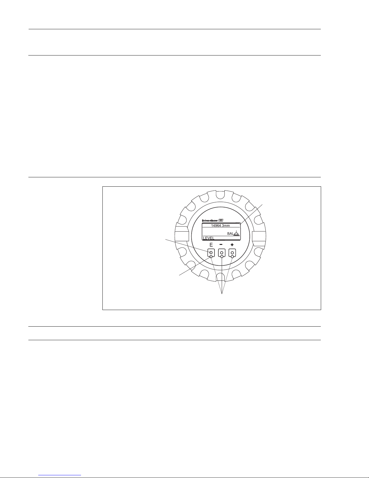
Operating concept Proservo NMS 5/7 is furnished with a four line illuminated liquid crystal display. With the E+H matrix driven
operation, configuration is simple. Using only three key, all parameters can be selected and modified. For
example:
• Operation - level; interface; spot & profile density, water dip, & tank bottom
• Current output
• Relay output
• Custody transfer
• Maintenance prediction
• Calibration, etc.
The display can be configured to be displayed in English, Japanese or Chinese. Measurement unit & decimal
point can be also configured within NMS matrix.
Operational Security
The programming information can be protected by software access codes that disable all programmable
parameters or by a hardware switch to prevent changes from remote transmission or the touch control keypad.
A self-diagnosis function checks for any operational failures.
Display(LCD)
Four line 16-digit illuminated display English, Japanese, Chinese selectable
Programming Three optical keys (touch control) for selection of matrix functions.
Memo function Memo of maintenance information.
3 optical operating element s
"Touch control"
Infrared transmitting
diaode
Infrared receiving
diaode
IIluminated LCD
Page 23

Proservo
Endress+Hauser 23
Advanced Maintenance
Maintenance Prediction Proservo NMS 5/7 will provide advance warning of required maintenance such as replacement of worn wire
etc. The operating life-span of electrical and mechanical parts of the Proservo NMS 5/7 are factory set within
the instruments memory. This information is checked involving with the built-in clock and compared and
registered in the instrument.
Automatic Displacer Weight
Compensation
The displacer can be checked for buildup or corrosion by comparing the measured weight of the displacer in
the air with the pre-programmed displacer weight. Proservo NMS 5/7 can be set to the periodical check for
the displacer weight, and any deviations in the weight will then be corrected and an alarm or memo initiated.
Automatic Compensation of
Wire Length
When the displacer is moved from the level position to the reference point (mechanical stop within the
instrument), the calibration can be checked. If there is any deviation outside the tolerance, then the instrument
will emit an alarm. If the deviation is within the tolerance (set by the customer), then an automatic recalibration
will be done. This function can be working manually or automatically in preset time intervals.
Maintenance The maintenance record can be accessed via the matrix and will provide information of alarm data (e.g. date,
time, alarm type). A memo function allows the user or an E+H Service Engineer to enter maintenance data
manually.
Proactive Safety Proactive safety diagnostic function warns of mechanical failure, and outputs maximum level value, e.g. 99999
to local display and fieldbus.
Page 24

Proservo
24 Endress+ Hauser
Certificates and Approval
Ex approvals TIIS
Ex d IIB T4
ATEX
EEx d IIB T6
EEx d IIB T6, Zone 0 (only for SS drum chamber)
EEx d IIC T6
EEx d IIC T6, Zone 0 (only for SS drum chamber)
EEx d IIB T6, -40 dec.
EEx d IIB T6, Zone 0 -40 degrees C.(only for SS drum chamber)
EEx d [ia] IIB T6
EEx d [ia] IIB T6, Zone 0 (only for SS drum chamber)
FM
XP - AIS Class I, Div 1, Groups CD
XP Class I, Div 1, Groups CD
CSA
Class I, Div 1, Groups CD
Custody transfer approvals PTB: Germany (pending for Chinese language version)
NMi: Netherlands
Overspill protection T
ÜV: Germany
External standards and
guidelines
EMC-Directive 89/336/EC
PE-Directive 97/23/EC
EN 10204-3.1B
OIML-R85/1998-NL-00.03
ISO 9001:2001
JIS Z9901:1998
Page 25
Proservo
Endress+Hauser 25
Ordering information
Proservo NMS5
010 Drum housing
1 0.2bar gauge; Alu.
2 0.2bar gauge; stainless steel
4 6bar gauge; Alu.
5 6bar gauge; stainless steel
6 25bar gauge; stainless steel
9 Special vesion
020 Protection class
0 Weather proof ; IP 67 / NEMA 4X
1 TIIS Ex d IIB T4
5 XP Class 1, Div. 1, Gr. CD, FM
6 Class 1, Div. 1, Gr. CD, CSA
F ATEX II 2G EEx d IIB T6
G ATEX II 1/2G EEx d IIB T6
H ATEX II 2G EEx d [ia] IIB T6
J ATEX II 1/2G EEx d [ia] IIB T6
N XP-AIS Class 1, Div.1, Gr.CD, FM: EEx d[ia]
O Class 1, Div.1, Gr.CD CSA EExd(ia)
Q ATEX II 1/2G EEx d IIC T6
R ATEX II 2G EEx d IIB T6, -40 dec
S ATEX II 1/2G EEx d IIB T6, -40 dec
T *TIIS Ex d(ia) IIB T4
Y Special vesion
030 Measuring function
A Level
B PTB Weights & Measures, Level
C NMi Weights & Measures, Level
D Multi measurement, Level, I/F level, Bottom, Density
E PTB Weights & Measures, Level, I/F level, Bottom, Density
F MNi Weights & Measures, Level, I/F level, Bottom, Density
G Density profile multi measurement, Level, I/F level, Bottom, Density
H PTB Weights & Measures, Density profile, Level, I/F level, Bottom, Density
J NMi Weights & Measures, Density profile, Level, I/F level, Bottom, Density
Y Special vesion
040 Primary (Digital) output
NEnraf BPM
P RS 485 Modbus
Q *Modbus, current loop, dual output
F Not selected
A Serial pulse (Sakura V1/MDP)
J Serial pulse (Sakura MDP)
B Serial pulse (Sakura BBB)
C Serial pulse (Sakura MIC + RS-232C)
D Serial pulse (Sakura MIC)
GHART (active)
HHART (passive)
L Whessoe matic 550+OVP=overvoltage protection
M Mark / Space
Y Special vesion
050 Secondary output
0 Not selected
1 Alarm contact, 4x SPST
2 4 - 20 mA, 2 channels selectable
3 4 x SPST + 4 - 20 mA, 2 channels
4 2 x SPST, Overspill protection
5 4 x SPST, 4 - 20 mA, 1 channel
9 Special vesion
NMS5- Product designation (part 1)
Page 26
Proservo
26 Endress+ Hauser
060 Signal input from field units
0 HART protocol (e.g. NMT, NRF)
1 HART + Pt100 Spot temp.
2 HART + Operation contact, 3digits
3 HART + Pt100 Spot temp.+ Operation contact
4 HART + 1 x status
5 HART + Pt100 Spot temp. + 1 x status
6 HART + Pt100 + Operation contact +1 x status
9 Special vesion
070 Element spacing
A Range: 0 -10m, AISI316 wire
B Range: 0 -16m, AISI316 wire
C Range: 0 -28m, AISI316 wire
L Range: 0 -36m, AISI316 wire
G Range: 0 -10m, AISI316 wire PFA covered wire
H Range: 0 -16m, AISI316 wire PFA covered wire
J Range: 0 -10m, Alloy C
K Range: 0 -16m, Alloy C
Y Special version
080 Cable entry
E Four thread G(PF)1/2"
F Four thread G(PF)3/4"
G Four thread NPT1/2"
H Four thread NPT3/4"
J Four thread PG 16
K Four thread PG 21
L Four thread M20
M Four thread M25
Y Special version
090 Process connection
A Flange JIS10 K 80A RF
C Flange JIS10 K 80A FF
E Flange JIS 20 K 80A RF (only for 25bar drum chamber)
G Flange ANSI 3" 150 Ibs RF
J Flange ANSI 3" 300 Ibs RF (only for 25bar drum chamber)
U Flange JIS10 K 150A RF
T Flange ANSI 6" 150 Ibs RF
L Flange DIN DN80 PN10 RF
N Flange DIN DN80 PN25 RF (only for 25bar drum chamber)
Q Flange JPI 3" 150 Ibs RF
S Flange JPI 3" 300 Ibs RF (only for 25bar drum chamber)
Y Special version
100 Power supply
3 85 - 264 VAC, 50/60 Hz
4 20 - 62 VDC, 20W/ 20 - 55 VAC, 50/60 Hz, 20VA
9 Special version
110 Displacer shape, diameter, material
B Conical 50 mm, PTFE
D Cylindrical 50 mm, AISI316 (standard)
K Cylindrical 40 mm, AISI316
N Cylindrical 30 mm, AISI316
R70 mm, W&M NMi
S 110 mm, W&M PTB
T Cylindrical 50 mm, AIloy C
U Cylindrical 50 mm, PTFE
V Cylindrical 40 mm, PTFE
W Cylindrical 30 mm, PTFE
Y Special version
NMS5- product designation (part2)
Page 27
Proservo
Endress+Hauser 27
120 O-ring; chamber finishing
0 NBR; Standard chamber
1 Silicon rubber, Standard chamber
2 Fluor rubber, Standard chamber
3 PTFE (Wire drum FKM), Basic version
4 PTFE (Wire drum FKM), PFA coated
5 Silicon rubber, PFA coated chamber
6 Neoprene (ammonia application), standards chamber
9 Special version
130 Options
A not selected
C With cleaning nozzle
D With gas purging nozzle
E
With guide wires (SUS316 standard)
G With relief valve
H With relief valve + pressure gauge
JSunshade
Y Special version
NMS5- Complete product designation
Page 28
Proservo
28 Endress+ Hauser
Proservo NMS7..
(Sanitary version)
010 Protection class
0 IP 67 / NEMA 4X
1 TIIS Ex d IIB T4
020 Measuring function
ALevel
B Level, I/F level, Density
Y Special version
030 Primary (Digital) output
NEnraf BPM
P RS485 Modbus
FNot selected
A Serial pulse (Sakura V1/MDP)
J Serial pulse (Sakura MDP)
B Serial pulse (Sakura BBB)
C Serial pulse (Sakura MIC + RS-232C)
D Serial pulse (Sakura MIC)
G HART (active)
H HART (passive)
L Whessoematic 550, with lightning protection
M Mark / Space
040 Secondary output
0 Not selected
1 Alarm contact, 4x SPST
2 4 - 20 mA , 2 channels selectable
3 4 x SPST + 4 - 20 mA, 2 channels
4 2 x SPST; Overspill protection
5 4 x SPST; 4 - 20 mA, 1 channel
050 Signal input from field units
0 HART protocol (e.g. NMT, NRF)
1 HART + Pt100 Spot temp.
2 HART + Operation contact, 3digits
3 HART + Pt100 Spot temp.+ Operation contact
4 HART + 1 x status
5 HART + Pt100 Spot temp. + 1 x status
6 HART + Pt100 + Operation contact +1 x status
060 Measuring range, wire material
A Range: 0 -10m, wire d=0.2 mm,AISI316
B Range: 0 -16m, wire d=0.2 mm,AISI316
C Range: 0 -10m, wire d=0.4 AISI316 PFA covered
D Range: 0 -16m, wire d=0.4 AISI316 PFA covered
Y Special version
070 Cable entry
A Four thread G(PF)1/2"
B Four thread G(PF)3/4"
C Four thread NPT1/2"
D Four thread NPT3/4"
E Four thread PG 16
F Four thread PG 21
G Four thread M20
H Four thread M25
Y Special version
080 Process Connection
A Flange JIS10 K 80A RF
B Flange JIS10 K 80A FF
C Flange ANSI 3" 150 Ibs RF
D Flange DIN DN80 PN10 RF
E Flange JPI 3" 150 Ibs RF
Y Special version
NMS7- Product designation (part 1)
Page 29
Proservo
Endress+Hauser 29
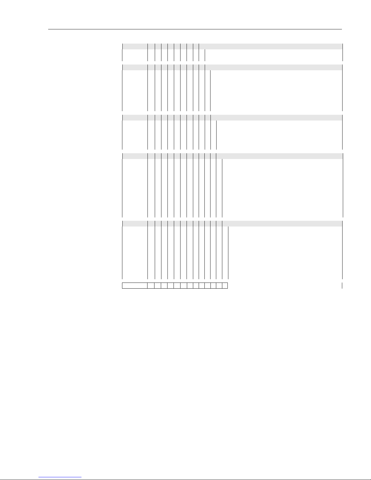
090 Power supply
0 85 - 264 VAC, 50/60 Hz
1 20 - 62 VDC, 20W/ 20 - 55 VAC, 50/60 Hz, 20VA
100 Displacer shape, diameter, material
A Cylindrical 50 mm; AISI316 buff finished
B Cylindrical 40 mm; AISI316 polished finished
C Cylindrical 30 mm, AISI316 polished finished
D Cylindrical 50 mm, PTFE
E Cylindrical 40 mm, PTFE
F Cylindrical 30 mm, PTFE
Y Special version
110 O-ring; chamber finishing
0 NBR; Standard chamber milling finished
1 Silicon; Standard chamber buff finished
2 Fluor rubber, basic version
5 Silicon rubber, PTFE coated chamber
9 Special version
120 Nozzle
A With cleaning nozzle PT 3/8" threaded
B With cleaning nozzle NPT 3/8" threaded
C With cleaning nozzle PF 3/8" threaded
D With gas purging nozzle PT 3/8" threaded
E With gas purging nozzle NPT 3/8" threaded
F With gas purging nozzle PF 3/8" threaded
G With cleaning + gas purging nozzle PT 3/8" threaded
H With cleaning + gas purging nozzle NPT 3/8" threaded
J With cleaning + gas purging nozzle PF 3/8" threaded
Y Special version,
130 Additional Option
A Not selected
B Sealing function
C Degreased
D Sun shade
E Sealing function + Degreased
F Sealing function + Sun shade
G Sun shade + Degreased
H Sealing function, Sun shade + Degreased
Y Special version
NMS7- Complete product designation
Page 30
Proservo
30 Endress+ Hauser
Accessories
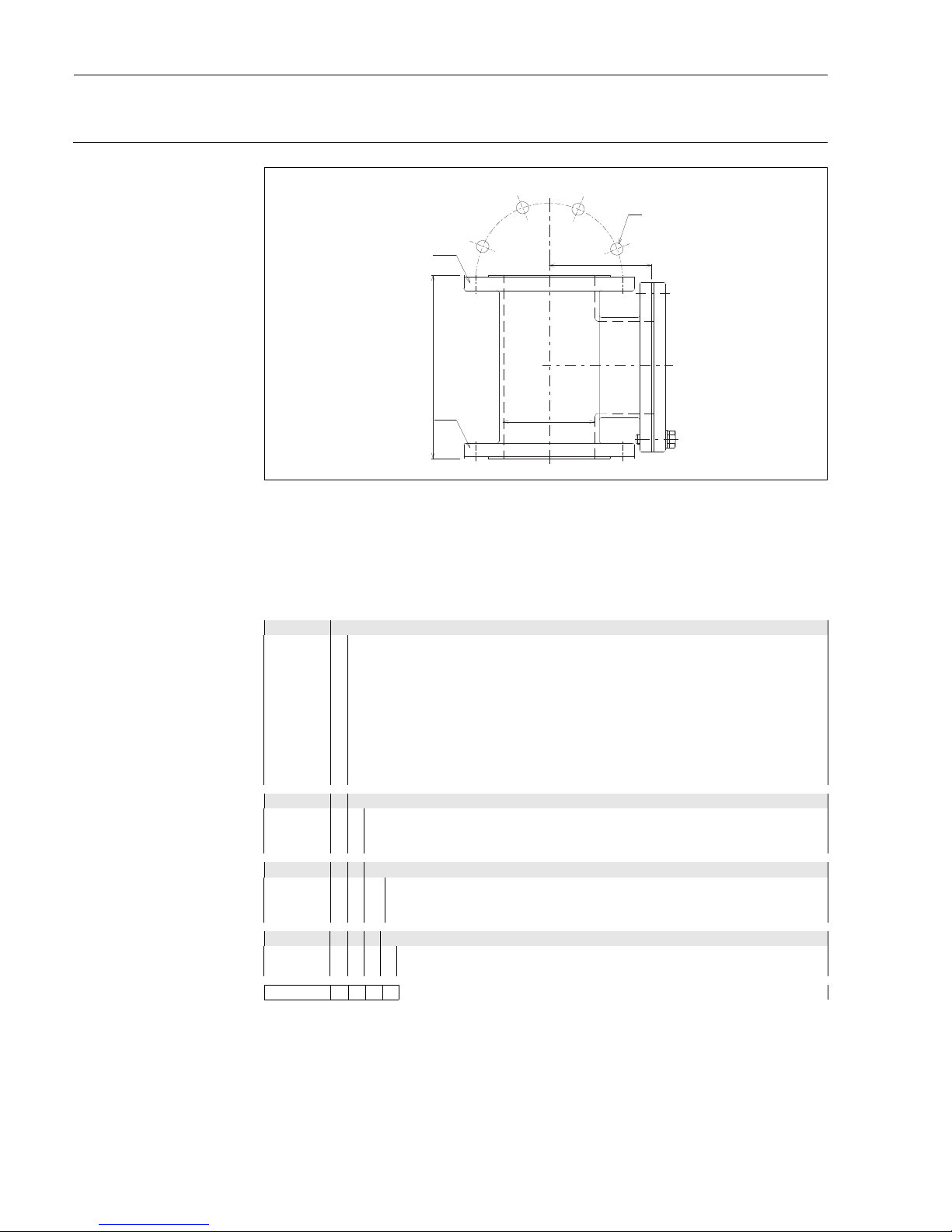
Calibration Chamber
Calibration chamber is recommended for use with tank level gauges in order to allow maintenance (removing
displacers), while tank is in service.
Standard chamber is 6" flange, with bolts & packing for NMS connection.
Note!
The dimensions differ depending on material, flange size. Please contact Endress+Hauaser for details.
NHC4HP (high pressure version)
10 Process Connection
A Flange JIS 10K 150A RF
C Flange JIS 10K 150A FF
E Flange JIS 20K 150A RF
G Flange ANSI 6" 150lbs RF
J Flange ANSI 6" 300lbs RF
L Flange DIN DN 150 PN 10 RF
N Flange DIN DN 150 PN 25 RF
Q Flange JPI 6" 150lbs RF
S Flange JPI 6" 300lbs RF
9 Special version
20 Material
2 Carbon steel (STPG370/SS400)
3 Stainless steel / SUS304
9 Special version
30 Bolts, Packing
0not used
1 Stainless steel 304 + Valker #6502
9 Special versiond
40 Pressure Gauge, Relief Valve
1used
9 Special version
NHC4HP- Complete product designation
172
300
Ø150
CALIBRATION CHAMBER
Flange
Flange
8 hole
Page 31
Proservo
Endress+Hauser 31
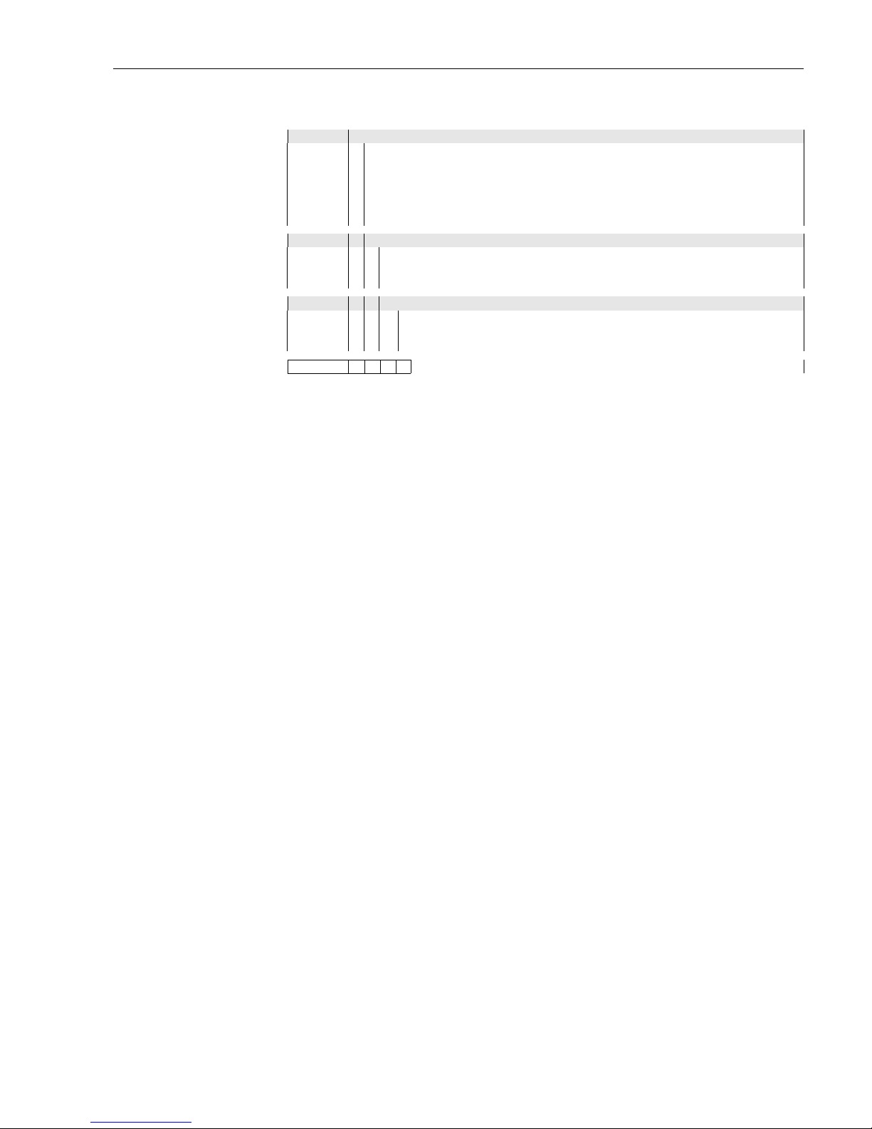
NHC4LP (low pressure version)
10 Process Connection
A Flange JIS 10K 150A RF
C Flange JIS 10K 150A FF
G Flange ANSI 6" 150lbs RF
L Flange DIN DN 150 PN 10 RF
Q Flange JPI 6" 150lbs RF
9 Special version
20 Material
1 Alu casting (AC4A)
3 Stainless steel / SUS304
9 Special version
30 Bolts, Packing
0not used
1 Stainless steel 304 + Valker #6502
9 Special version
NHC4LP- Complete product designation
Page 32
Proservo
32 Endress+ Hauser
Power+Control Switch
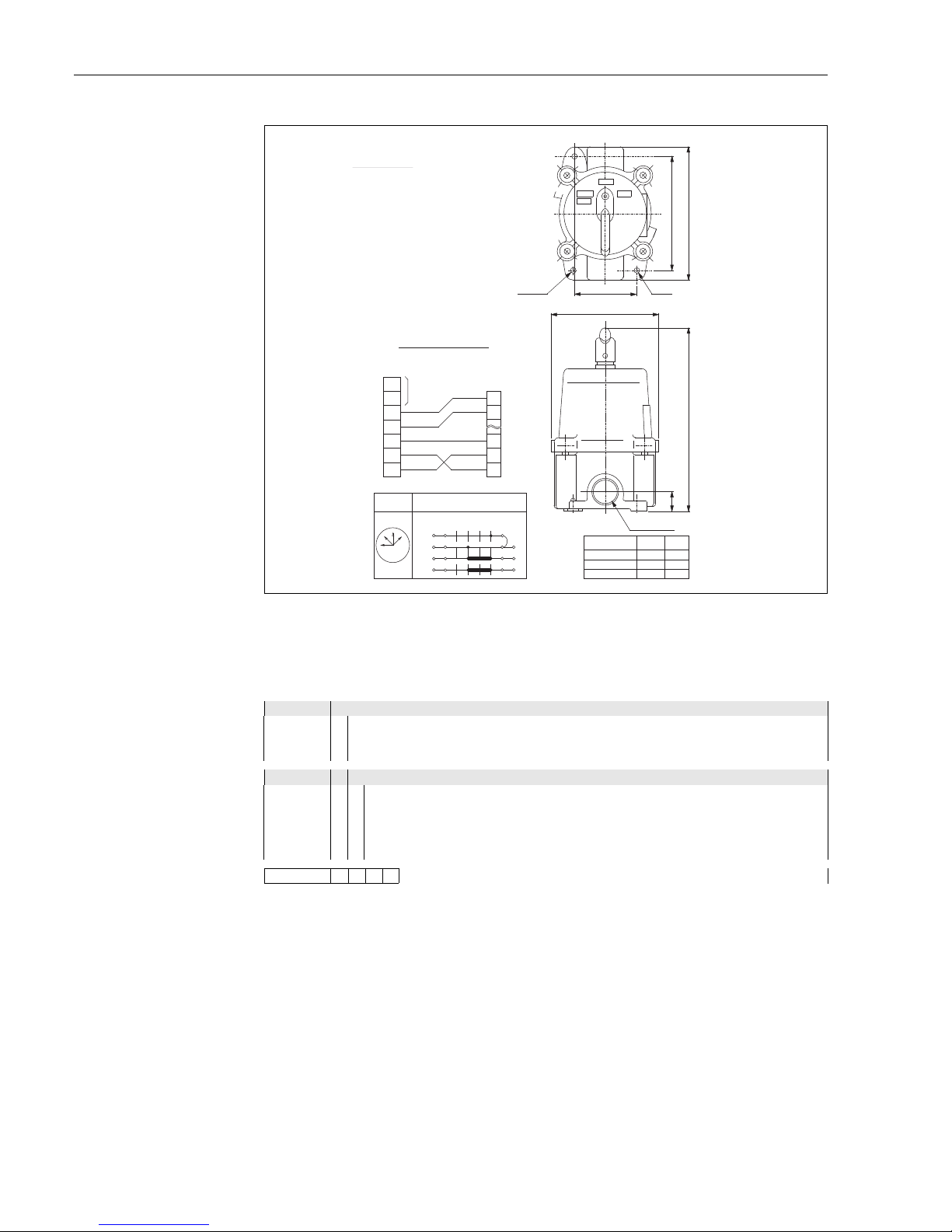
Power & Control Switch is used for tank gauges field mounted, for tank gauges. It provides additinal switching
of operation contacts of the gauge in order to control the gauge’s operation such as lift up displacer.
NHS8
10 Approval
1 Weather proof IP67
2 Flame proof (JIS d3aG5)
9 Special version
20 Cable entry
02 x thread G3/4
12 x thread G1
22 x thread NPT3/4
32 x thread NPT1
9 Special version
NHS8- Complete product designation
Power + Control Swith
SPECIFICATIONS
RATED VOLTAGE
AC110 / 220V
RATED CURRENT
6A / 5A
ALLMINIUM ALLY CASTING
HOUSING
TERMINAL BOX
IRON CASTING
STRUCTURE
EXPLOSION PROOF
d3aG5
NO.OF CERTIFICATE T3875
CONNECTION DIAGRAM
Term.No
Power Supply
NMS
Term.No
NHS8
1
2
3
4
5
6
7
1
2
16
17
18
Handle
position
Wiring
LIFT
INST
STOP
OFF
7
6
4
3
5
2
1
OFF
STOP
INST
LIFT
Cable Entry
PF (G)1/2
PF (G) 3/4
PF (G)1
h (mm) B
17
20
24
140
140
145
Cable entry
193
113
65
Grounding
LIFT
STOP
OFF
2 - Ø7
120
B
INST
h
Power L
Power N
COM
CRT1
CRT2
Page 33
Proservo
Endress+Hauser 33
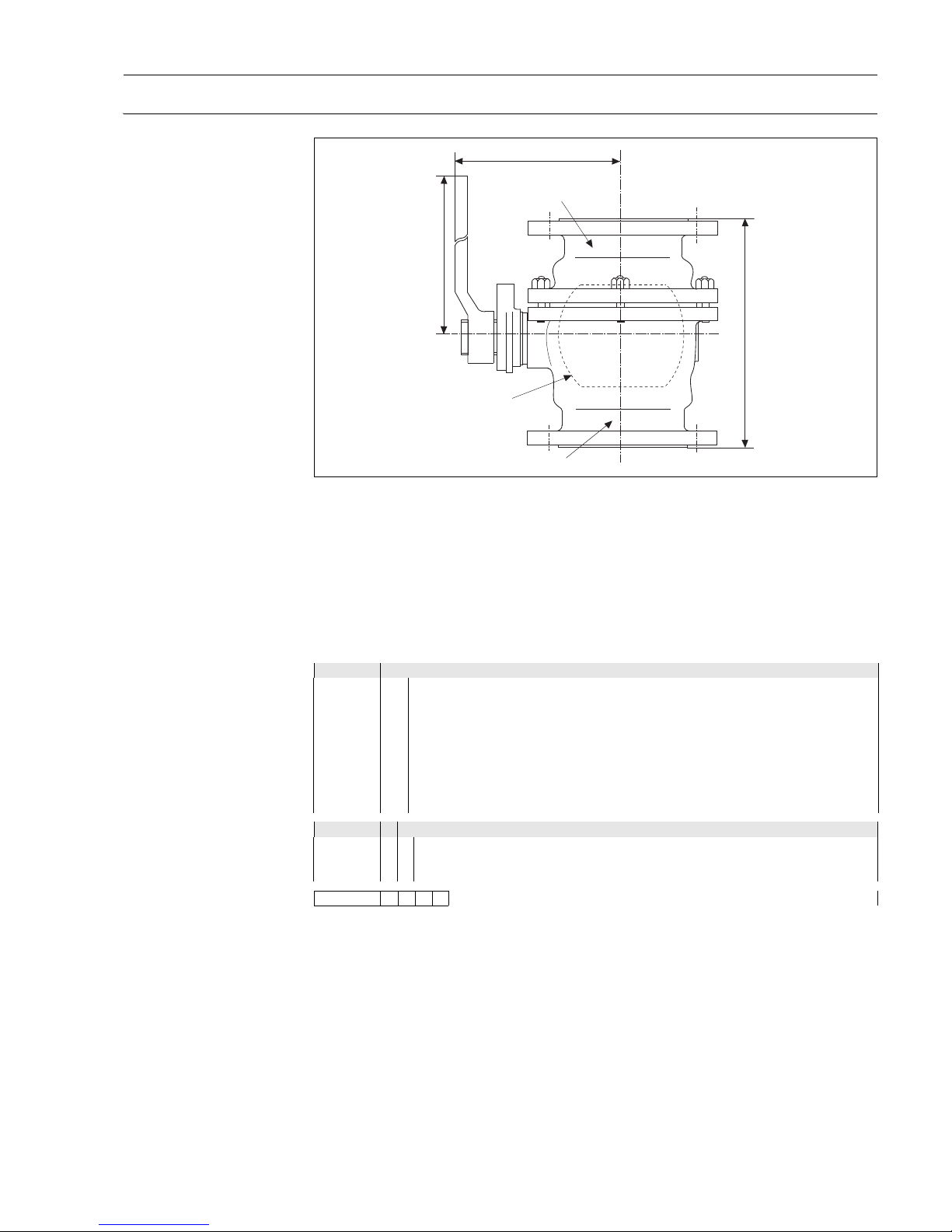
Ball Valve
Ball valve is recommended for use with tank level gauges in order to allow maintenance such as removing displacers, while tank is in service.
Standard ball valve with ANSI flanges. Ball material is SS304, seat material is PTFE.
Note!
The dimensions differ depending on material, flange size. Please contact Endress+Hauser for details.
NHV4A (ANSI flanges)
Standard ball valve with ANSI flanges. Ball material is SS304, seat material is PTFE.
10 Process Connection ; Body
C31 Flange ANSI 3" 150lbs RF; mild steel
C33 Flange ANSI 3" 300lbs RF; mild steel
C61 Flange ANSI 6" 150lbs RF; mild steel
C63 Flange ANSI 6" 300lbs RF; mild steel
S31 Flange ANSI 3" 150lbs RF; SS304
S33 Flange ANSI 3" 300lbs RF; SS304
S61 Flange ANSI 6" 150lbs RF; SS304
S63 Flange ANSI 6" 300lbs RF; SS304
Y99 Special version
20 Ball Type
A full bore
B reduced bore
9 Special version
NHV4A- Complete product designation
Ball
Body cap
Body
190
153
400
Page 34
Proservo
34 Endress+ Hauser
NHV4J (JIS flanges)
For body in mild steel and in SS304, ball material is SS304, ball material is SS304. For body in SS316, ball material is SS316. Seal material is PTFE.
10 Process Connection ; Body
C11 Flange JIS 10K 80A RF; steel
C12 Flange JIS 10K 150A RF; steel
C21 Flange JIS 20K 80A RF; steel
C22 Flange JIS 20K 150A RF; steel
S11 Flange JIS 10K 80A RF; SS316
S12 Flange JIS 10K 150A RF; SS316
S21 Flange JIS 20K 80A RF; SS316
S22 Flange JIS 20K 150A RF; SS316l
H11 Flange JIS 10K 80A RF; steel
H12 Flange JIS 10K 150A RF; steel
H21 Flange JIS 20K 80A RF; steel
H22 Flange JIS 20K 150A RF; steel
Y99 Special version
20 Ball Type
A full bore
B reduced bore
9 Special version
NHV4J- Complete product designation
Page 35
Proservo
Endress+Hauser 35
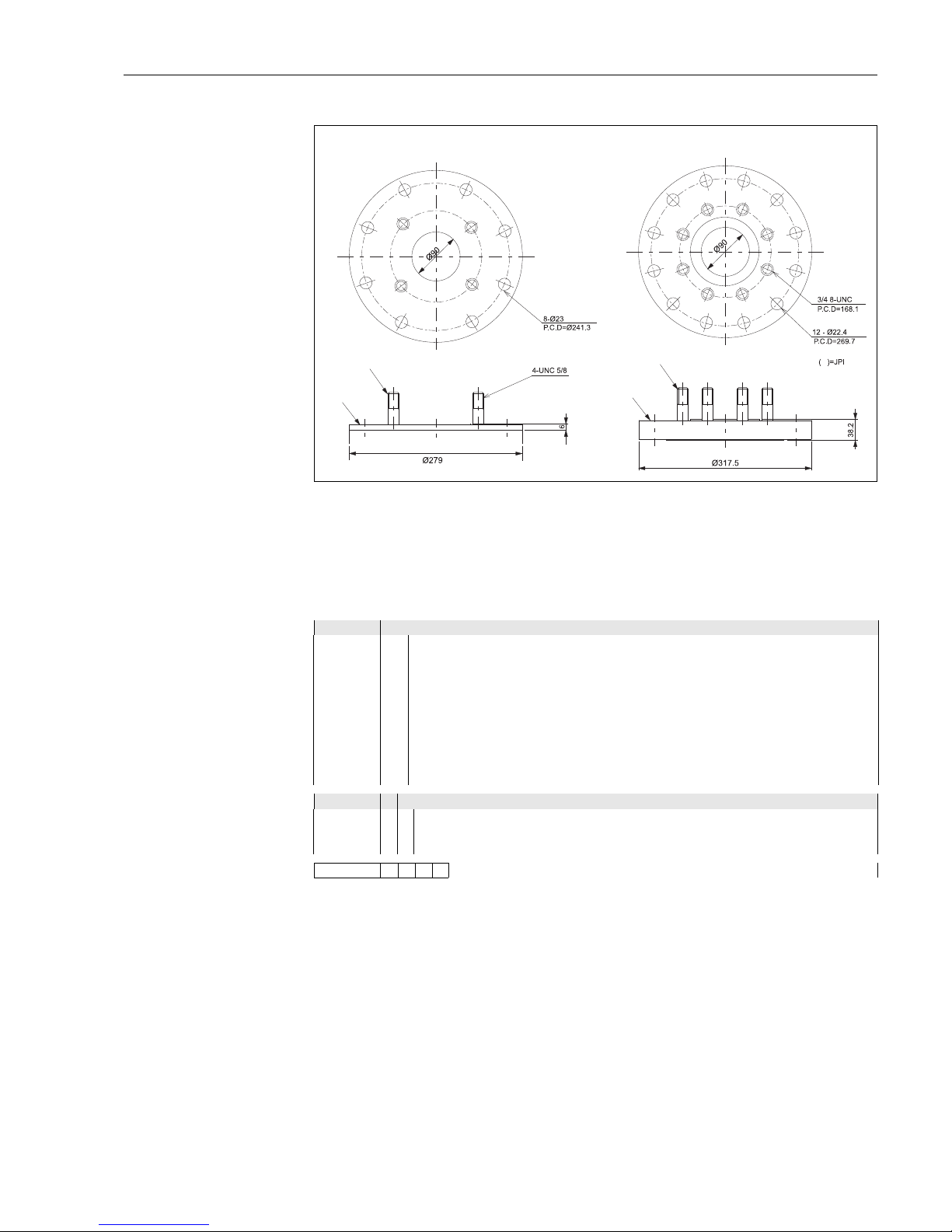
Reducing Flange
Mounting with Guide Wire requires the reducing flange. Also, it is required to match customer’s nozzle with
Proservo flange.
Proservo connection is always 3"/DN80. The reducing flange is equipped with stud bolts for the Proservo uge
connection.
NHF4
10 Process Connection ; Body
A Flange JIS 10K 150A RF
C Flange JIS 10K 150A FF
E Flange JIS 20K 150A RF
G Flange ANSI 6" 150lbs RF
J Flange ANSI 6" 300lbs RF
L Flange DIN DN150 PN10 RF
N Flange DIN DN150 PN25 RF
Q Flange JPI 6" 150lbs RF
S Flange JPI 6" 300lbs RF
Y Special version
20 Flange Material
0 Mild steel (JIS SS41)
1 Stainless steel SS304
9 Special version
NHF4- Complete product designation
Low pressure (JPI)
High pressure (ANSI)
Stud Bolt
Flange
Stud Bolt
Flange
Page 36

Proservo
36 Endress+ Hauser
Supplementary Documentation
Technical Information TI 039N
Technical Information Prothermo NMT 535
TI 042N
Technical Information Prothermo NMT 539
TI 008N
Technical Information Promonitor NRF 560
TI 014N
Technical Information Tank Computer NRM 571
Operating Manual BA1001N
Operating Manual Proservo NMS5/7 series
Compact Instructions KA 001N
Compact Instruction Whessoemtric 550
KA 002N
Compact Instruction RS485 Modbus
Safety Instructions XA 006N
Proservo NMS5/7 series - ATEX II 2/1 G, II 2 G (KEMA)
XA 007N
Proservo NMS5/7 series - ATEX II 2/1 G, II 2 G (PTB)
XA 001N
Proservo NMS5/7 series - ATEX II 2/1 G, II 2 G (ZELM)
Page 37

Proservo
Endress+Hauser 37
Appendix
Stainless Steel conversion
table
The stainless steel material used in products of Endress + Hauser Yamanashi normally have expressions
according to Japanese industrial standards, such as JIS. Each country or region may have different expressions
place to place.
The following conversion table contains the expression of equivalent stainless steel material based on the
chemical composition and mechanical properties.
Note!
Since each standard carries its own mechanical and scientific definition, some expressions may not have the
straight conversion from the Japanese standard. Consult with the local authority or legislature to ensure the
proper comparision of the applied standard prior to determining specification.
Country Standard Expressions
Japan JIS SUS304 SUS304L SUS316 SUS316L
Germany DIN 17006 X5 CrNi 18 10
X5 CrNi 18 12
X2 CrNi 18 11 X5 CrNiMo 17 12 2 /
1713 3
X2 CrNiMo 17 13 2
W.N. 17007 1.4301 1.4303 1.4306 1.4401 / 1.4436 1.4404
France AFNOR Z 6 CN 18-09 Z 2CN 18-10 Z 6 CND 17-11 / 17 12 Z2 CND 17-12
Italy UNI X5 CrNi 1810 X2 CrNi 1911 X5 CrNiMo 1712 /
1713
X2 CrNiMo 1712
U.K. BSI 304S15 / 304S16 304S11 316S31 / 316S33 316S11
U.S.A. AISI 304 304 L 316 316L
U.E. EURONORM X6 CrNi 1810 X3 CrNi 1810 X6 CrNiMo 17 12 2 /
17 13 3
X3 CrNiMo 17 12 2
Spain UNE X6 CrNi 19-10 X2 CrNi 19-10 X6 CrNiMo 17-12-03 X2 CrNiMo 17-12-
03
Russia GOST 08KH18N10
06KH18N11
03KH18N11 _ 03KH17N14M2
- ISO 11 10 20 19
- ASME S30400 S30403 S31600 S31603
Page 38

Endress + Hauser Yamanashi Co., Ltd.
862-1 Mitsukunugi Sakaigawa-cho
Fuefuki-shi Yamanashi,
406-0846 Japan
Phone: ++81 55 266 4964
Fax: ++81 55 266 4969
http://www.endress.com
TI 006N/08/en/04.09
Software Ver. 4.27C
FM+SGML 6.0
Proservo
 Loading...