

Page 1
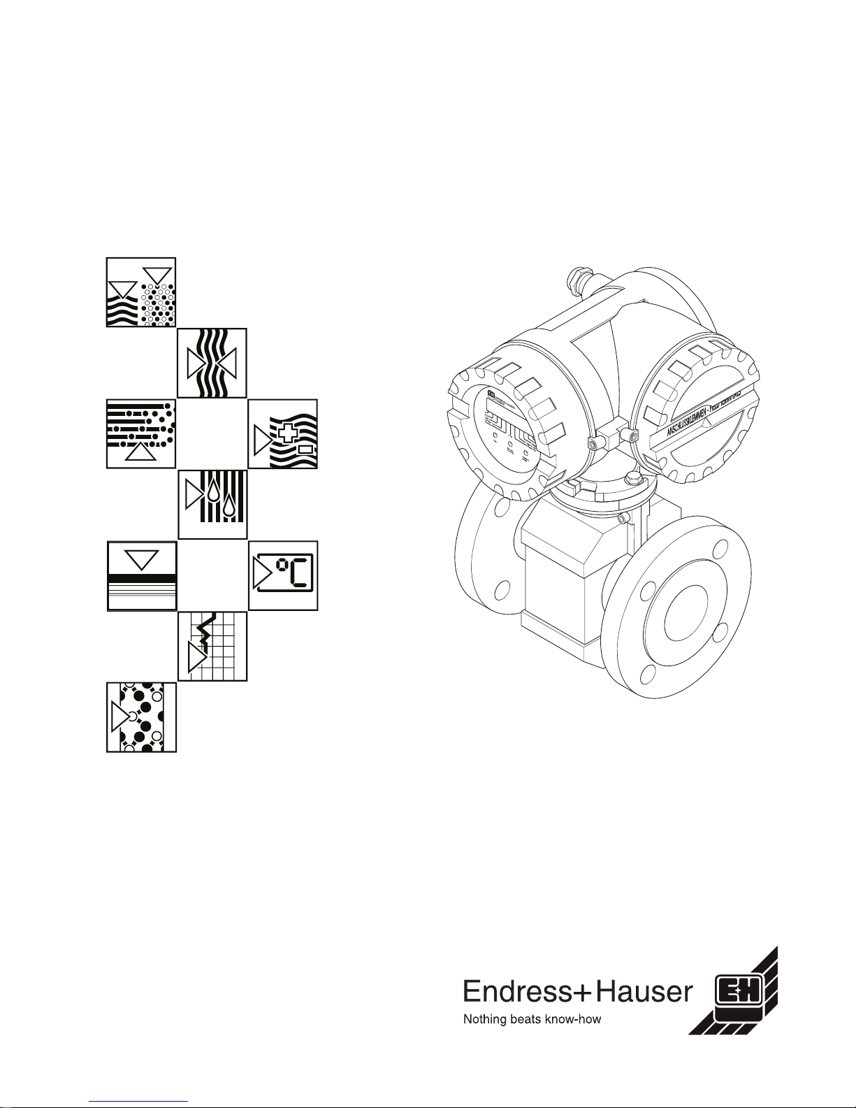
promag 30
Electromagnetic
Flow Measuring System
BA 008D/06/e/06.96
No. 50063716
valid from software version
V3.01.XX (measuring amplifier)
Operating Manual
Page 2
Safety Instructions
Please observe without fail the safety instructions in Chapter 1 (page 5).
Warning!
Documentation for Ex instruments
Instruments which are used in the explosion hazardous area
are supplied with a separate “Ex documentation”, which is an
integral part of this Operating Manual.
The instructions and connected loads provided in this
supplement must absolutely be observed.
An appropriate icon is shown on the front of this document
according to the approval given and the test centre.
Safety Instructions Promag 30
2 Endress+Hauser
Page 3

ContentsContents
1. Safety Instructions . . . . . . . 5
1.1 Correct Usage . . . . . . . . . . . 5
1.2 Dangers and Notes . . . . . . . . . 5
1.3 Personnel for Installation, Start-up and
Operation . . . . . . . . . . . . . 6
1.4 Repairs, Dangerous Chemicals . . . . 6
1.5 Technical Improvements . . . . . . . 6
2. System Description . . . . . . 7
2.1 Fields of application . . . . . . . . . 7
2.2 Principle of measurement . . . . . . . 7
2.3 The Promag 30 measuring system . . . 8
2.4 Design of the measuring system . . . 10
3. Mounting and Installation . . . 13
3.1 General Information . . . . . . . . 13
3.2 Transport instructions for Promag
from > DN 350 / 14" . . . . . . . . 14
3.3 Mounting Instructions . . . . . . . 15
3.4 Mounting the sensor . . . . . . . . 18
3.5 Turning the transmitter housing
and local display (compact version) . . 23
3.6 Mounting the transmitter
(remote-mounted version) . . . . . . 24
3.7 Potential equalization . . . . . . . 25
3.8 Earthing in an area with severe
interference . . . . . . . . . . . 26
4. Electrical Connection . . . . . 27
4.1 General information . . . . . . . . 27
4.2 Connection to the transmitter . . . . 27
4.3 Connection of the remote version . . . 28
4.4 Wiring diagrams . . . . . . . . . 29
4.5 Cable specifications . . . . . . . . 31
5. Operation and Commissioning . 33
5.1 Instrument Functions . . . . . . . . 33
5.2 Setting unit parameters with miniature
switches . . . . . . . . . . . . . 37
5.3 Local display . . . . . . . . . . . 42
5.4 Commissioning . . . . . . . . . . 44
6. Fault Location and Remedies . . 45
6.1 Behaviour of the measuring equipment
in the event of a fault or alarm . . . . 45
6.2 Instructions for fault location and
remedies . . . . . . . . . . . . 46
6.3 Replacing the transmitter electronics . 47
6.4 Replacing the fuse . . . . . . . . 49
6.5 Repairs . . . . . . . . . . . . . 49
7. Technical Data . . . . . . . . 51
7.1 Dimensions and weights . . . . . . . 51
7.2 Technical data: Sensor . . . . . . . 59
7.3 Technical data: Transmitter and
measuring system . . . . . . . . . 66
7.4 Nominal diameter and flow rate . . . . 67
7.5 Error limits . . . . . . . . . . . . 68
Index . . . . . . . . . . . . . 69
Promag 30 Contents
Endress+Hauser 3
Page 4

Promag 30
4 Endress+Hauser
Page 5
1. Safety Instructions
1.1 Correct Usage
• The Promag 30 is only to be used for measuring the flow of conductive fluids.
• The manufacturer assumes no liability for damage caused by incorrect use of the
instrument.
1.2 Dangers and Notes
All instruments are designed to meet state-of-the-art safety requirements, have been
tested, and have left the works in an operationally perfectly safe condition. The
devices were developed according to EN 61010 “Protection Measures for Electronic
Equipment for Measurement, Control, Regulation and Laboratory Procedures”.
A hazardous situation may occur if the flowmeter is not used for the purpose it was
designed for or is used incorrectly. Please carefully note the information provided in
this Operating Manual indicated by the pictograms:
Warning!
A “warning” indicated actions or procedures which, if not performed correctly, may
lead to personal injury or a safety hazard.
Please strictly observe the instructions supplied and proceed carefully.
Caution!
A “caution” indicates actions or procedures which, if not performed correctly, may
lead to faulty operations or the destruction of the instrument.
Please strictly observe the respective instructions.
Note!
A “note” indicates actions or procedures which, if not performed correctly, may
indirectly affect operations or lead to an unexpected instrument response.
Warning!
Promag 30 1. Safety Instructions
Endress+Hauser 5
Page 6
1.3 Personnel for Installation, Start-up and Operation
• Mounting, electrical installation, start-up and maintenance of the instrument may
only be carried out by trained personnel authorized by the operator of the facility.
Personnel must absolutely and without fail read and understand this Operating
Manual before carrying out its instructions.
• The instrument may only be operated by personnel who are authorized and trained
by the operator of the facility. All instructions in this manual are to be observed
without fail.
• With special fluids incl. those used for cleaning, E+H will be pleased to supply
information concerning the chemical resistance properties of wetted parts.
• The installer has to make sure that the measuring system is correctly wired up
according to the wiring diagrams. The measuring system is to be grounded.
• Please observe all provisions valid for your country and pertaining to the opening
and repairing of electrical devices.
1.4 Repairs, Dangerous Chemicals
The following procedures must be carried out before a Promag 30 is sent to
Endress+Hauser for repair:
• A note must always be enclosed with the instrument, containing a description of the
fault, the application, and the chemical and physical properties of the product
being measured.
• Remove all residue which may be present. Pay special attention to the gasket grooves
and crevices where fluid may be present. This is especially important if the fluid is
dangerous to health, e.g. corrosive, poisonous, carcinogenic, radioactive, etc.
• No instrument should be returned to us without all dangerous material being
removed first (e.g. in scratches or diffused through plastic).
Incomplete cleaning of the instrument may result in waste disposal or cause harm to
personnel (burns, etc). Any costs arising from this will be charged to the owner of the
instrument.
1.5 Technical Improvements
The manufacturer reserves the right to modify technical data without prior notice. Your
local E+H Sales Office will supply you with all current information and any updates to
this Operating Manual.
Danger of electrical shock!
With the housing cover removed, protection against accidental contact
is no longer present. Components with high voltages are exposed below the
local display. When programming according to section 5.3, avoid any contact
with the electronic components which lie below the local display, and do not
use any electrically conductive object to depress the programming keys.
1. Safety Instructions Promag 30
6 Endress+Hauser
Page 7
2. System Description
2.1 Fields of application
With the Promag 30 measuring system it is possible to obtain precise magnetoinductive measurements of flow at low cost. All liquid media with a minimum
conductivity of 5 µS/cm can be measured, e.g.:
• acids, alkalis, pastes, pulps
• drinking water, waste water, sewage sludge
• milk, beer, wine, mineral water, yoghurt, molasses
2.2 Principle of measurement
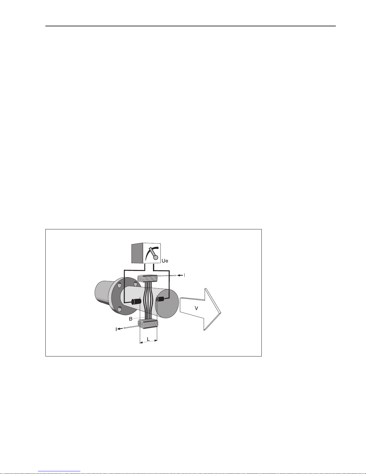
In accordance with Faraday’s law of induction, a voltage is induced in a conductor
that is moved through a magnetic field. In the magneto-inductive principle of
measurement the flowing medium represents the moving conductor. The induced
voltage is proportional to the flow velocity and is fed to the measuring amplifier by a
pair of electrodes. Across the cross-section of the pipe the flow volume is calculated.
The DC magnetic field is generated by a switched direct current of alternating
polarity. Together with the patented “Integrated Autozero Circuit” this assures a stable
zero point and makes the measurement independent of the medium and insensitive to
entrained solid particles. In our works every unit is calibrated on modern calibrating
facilities, referable to international standards. There is no need for it to be adapted to
suit changing media.
U
e
=B ⋅ L ⋅ v
Q=v ⋅ A
U
e
= induced voltage
B = magnetic induction
L = distance between electrodes
v = flow velocity
Q = volume flow
A = pipe cross-section
ba008y01
Fig. 1
Promag 30 2. System Description
Endress+Hauser 7
Page 8
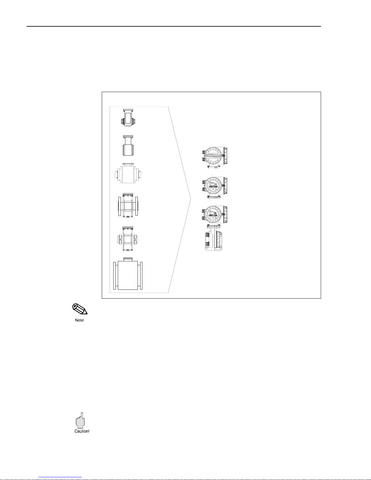
2.3 The Promag 30 measuring system
The Promag measuring system is fully modular, both mechanically and electrically.
The equipment can be extended by exchanging electronic boards. Thus the
measuring point can be optimally equipped and updated. The illustration below gives
an overview of the complete Promag 30 measuring system.
Note!
The Promag 33 system enhances the advantages of Promag 30 by providing the
following properties:
• E+H matrix-driven operation (12 languages)
• Two-line, illuminated display
• Batching with integral preset counter
• Ability to communicate
• Empty pipe detection (EPD)
You can find information on the special properties of the Promag 33 measuring system
in the “Technical Information Promag 33” TI No. 027D/06/e.
Caution!
The Promag 30 and the Promag 33 measuring systems are available with various
hazardous area approvals. Your E+H representative will be pleased to supply further
information on the available approvals. Approval relevant information can be found in
the supplement to this operating manual which can also be ordered from your
E+H representative.
•
Power supply board 85...260 V AC
or
•
Power supply board 20...55 V AC,
16...62 V DC
•
Amplifier board with
Pulse output
Current output
Status output
Auxiliary input
•
Local display (optional)
Sensor Equipment of transmitter
Promag A
DN 2...25
Promag D
DN 25...100
Promag F
DN 15...300
Promag F
mit DIN 11851
DN 15...100
ba008y02
Promag H
DN 25...100
Promag 30
Promag F
DN 350...2000
Fig. 2
2. System Description Promag 30
8 Endress+Hauser
Page 9
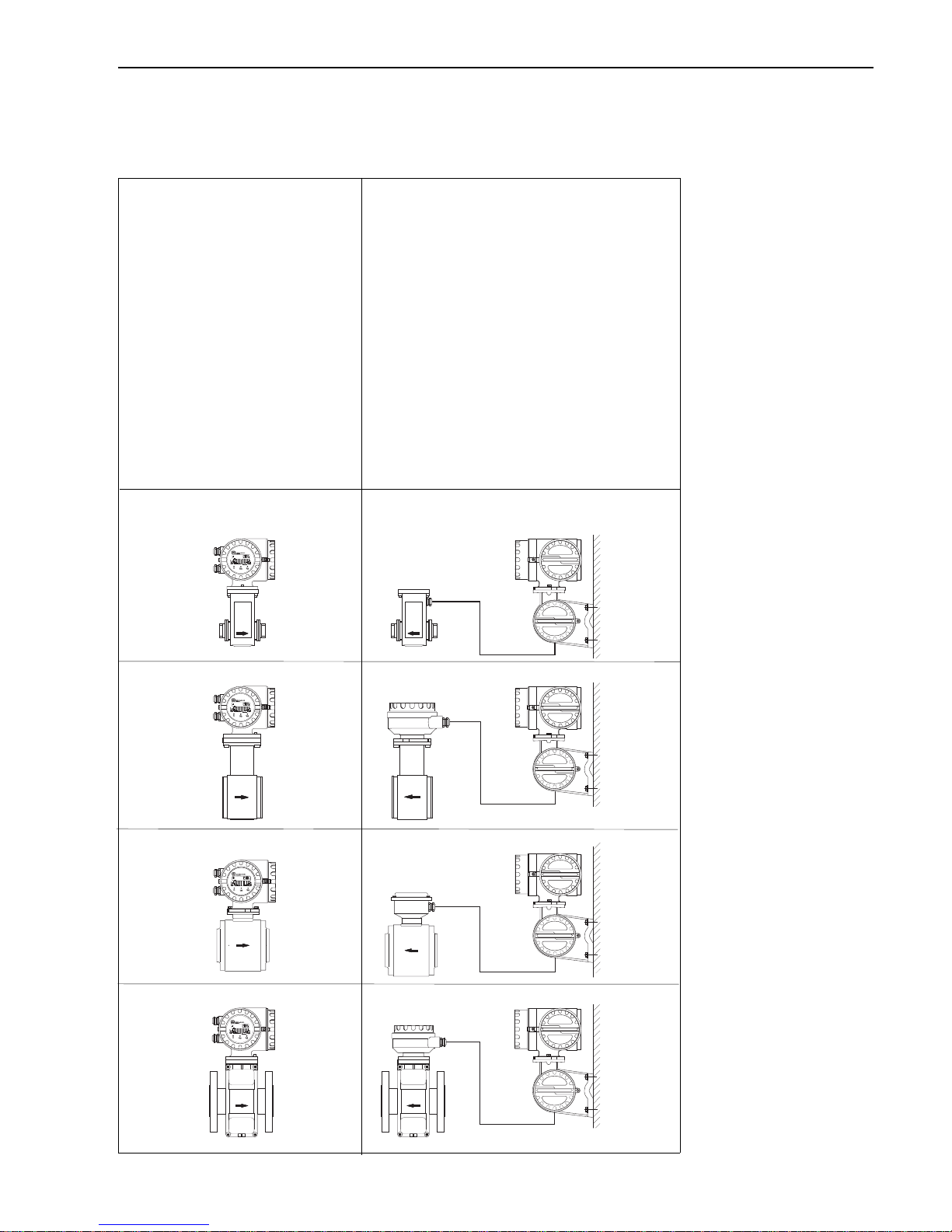
The measuring equipment comprises:
• Transmitter Promag 30 and
• Sensor Promag A, D, F or H
Compact vers ion
The Promag 30 transmitter
and the sensor together form
a mechanical unit.
Promag 30 A
Promag F
Promag 30
Promag 30 F
Promag 30 H
Promag D
Promag 30
Promag A
Promag 30
Promag 30 D
Promag 30
Promag H
Transmitter
Sensor
ba008y03
Remote-mounted version (FS version or FL version)
The transmitter is mounted remote from the sensor:
FS version
•
Up to 10 m distance meduim conductivity
min. 5 µS/cm
•
From 10…200 m distance max. cable length in terms
of the medium conductivity
(5...200 µS/cm)
FL version
•
Max. cable length 200 m, not dependent on
conductivity.
•
No EPD available.
•
The electrical connection between transmitter and
sensor is made in the connection housing
(exception: Promag A).
The wall mounting bracket for the transmitter is supplied.
Fig. 3
Promag 30 2. System Description
Endress+Hauser 9
Page 10
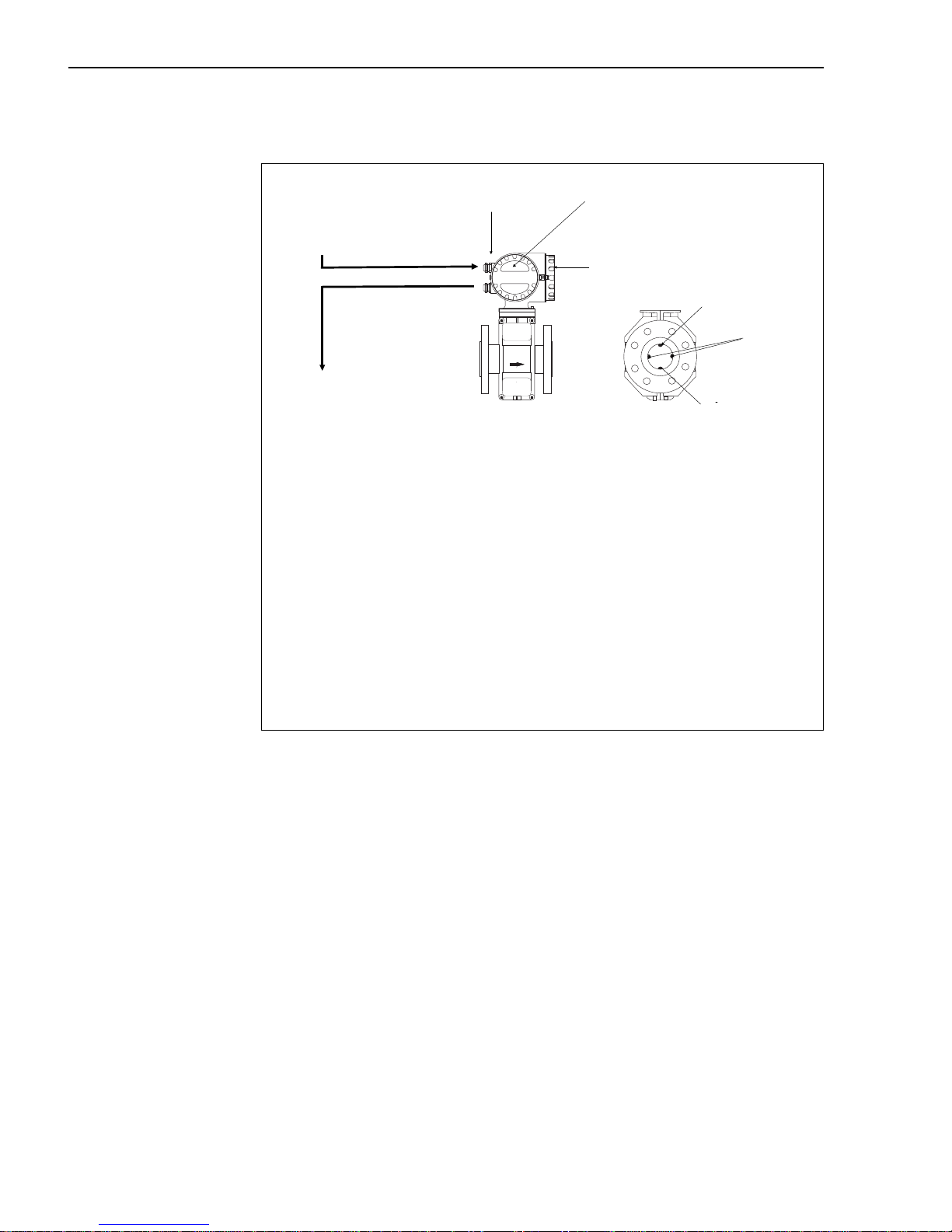
2.4 Design of the measuring system
(considering Promag 30 F as example)
Operation/Local display
Inside the housing of the transmitter there are miniature switches with which
altogether six operating parameters can be set (see page 37):
• Current range 0/4...20 mA
• Full-scale value scaling (volume/time), 8 steps
• Pulse weighting in decadic steps (volume), 8 steps
• Engineering units
• Function of the status output
Output of system/process errors
Flow direction recognition
• Creep suppression (on/off)
Using the Promag 30 local display, important parameters can be read off and
controlled at the measuring point directly:
• Flow rate and/or totaliser value
• Technical units (SI/US units)
• Process variables (e.g. creep rate, partial pipe filling)
• Error messages
Using the three operating keys, it is also possible to select and activate various
functions. A small pin is used to press the keys down (keep pressed for
approx. 0.5...0.8 s).
Power supply*
85...260 V AC 45...65 Hz
20... 55 V AC
16... 62 V DC
Cable entry
Sensor
Measuring
electrodes
Reference electrode
Screw cover of electronic
compartment (6 parameters can
be set here with internal miniature
switches)
Option: local display
Screw cover
Terminal compartment
ba008y04
Empty pipe
detection electrode
Outputs*
Current output active
galvanically separated
0/4...20 mA
R
L
≤
700
Ω
Pulse output Open Collector, passive
galvanically separated
0...400 Hz
Status output Open Collector, passive
galvanically separated
configurable for:
•
output of system or process errors
•
detection of the direction of flow
Auxiliary input The auxiliary voltage to be applied
to activate the function is in the
region of 3...30 V DC
•
Measured value suppression
•
Totalizer reset (with local display only)
* Technical data: see Chapter 7
Fig. 4
2. System Description Promag 30
10 Endress+Hauser
Page 11

Dynamic response
The Promag 30 measuring amplifier has a very high dynamic response of over
1000:1. It measures at medium velocities from less than 10 mm/s to over 10 m/s with
the specified accuracy. When the flow is pulsating, the amplifier is not over-driven
even above the end value setting at maximum speeds up to 12.5 m/s. There is then
no falsification of the measured value, provided the outputs are not over-driven.
Memory (DAT)
DAT is an exchangeable memory module. Stored in it are all characteristic data of the
sensor, such as calibrated quantities, nominal diameter, sensing rate, version, serial
number. When the transmitter has been changed, the previous DAT memory is
inserted in the new transmitter. When the measuring system is started, the measuring
point continues to operate with the data stored in the DAT memory. Thus the DAT
concept assures maximum safety and optimum ease of operation when components
of the equipment are exchanged.
Safety
• A comprehensive self-monitoring facility of the measuring system assures high
safety. Any system error messages (coil-current error, amplifier error, DAT error,
EEPROM error, ROM error, RAM error) or a power supply failure that do occur are
emitted at the configured status output.
• In the event of a power supply failure all data of the measuring system are securely
stored in the EEPROM (without a backup battery).
• The Promag 30 measuring system fulfils the safety requirements according to
EN 61010 “Protection Measures for Electronic Equipment for Measurement,
Control, Regulation and Laboratory Procedures”, and the general requirements
for electromagnetic compatibility (EMC) according to EN 50081 Part 1 and 2 /
EN 50082 Part 1 and 2 as well as the NAMUR recommendations.
• IP 67 protection (EN 60529) is standard for the transmitter and sensor (remote or
compact version). The sensor is also optionally available in IP 68.
Promag 30 2. System Description
Endress+Hauser 11
Page 12

nichts
nichts
Promag 30
12 Endress+Hauser
Page 13
3. Mounting and Installation
Warning!
• Pay consistent attention to the notes in this chapter regarding to assure reliable
measurement.
• For explosion protected instruments the mounting regulations and the technical
data may differ from those stated here. Please refer to the Ex supplement of this
operating manual.
3.1 General Information
Type of protection IP 67 (EN 60529)
The instruments fulfils all requirements for IP 67. In order to assure the type of
protection IP 67 after installation in the field or servicing, it is essential to comply with
the following points:
• The housing gaskets must be clean
and undamaged when inserted in the
sealing groove. If necessary, the
gaskets must first be dried, cleaned
or renewed.
• All screws in the housing and the
screw cover must be screwed up
tight.
• The cables used for connection must
possess the stipulated outside
diameter (see page 59, 60, 66).
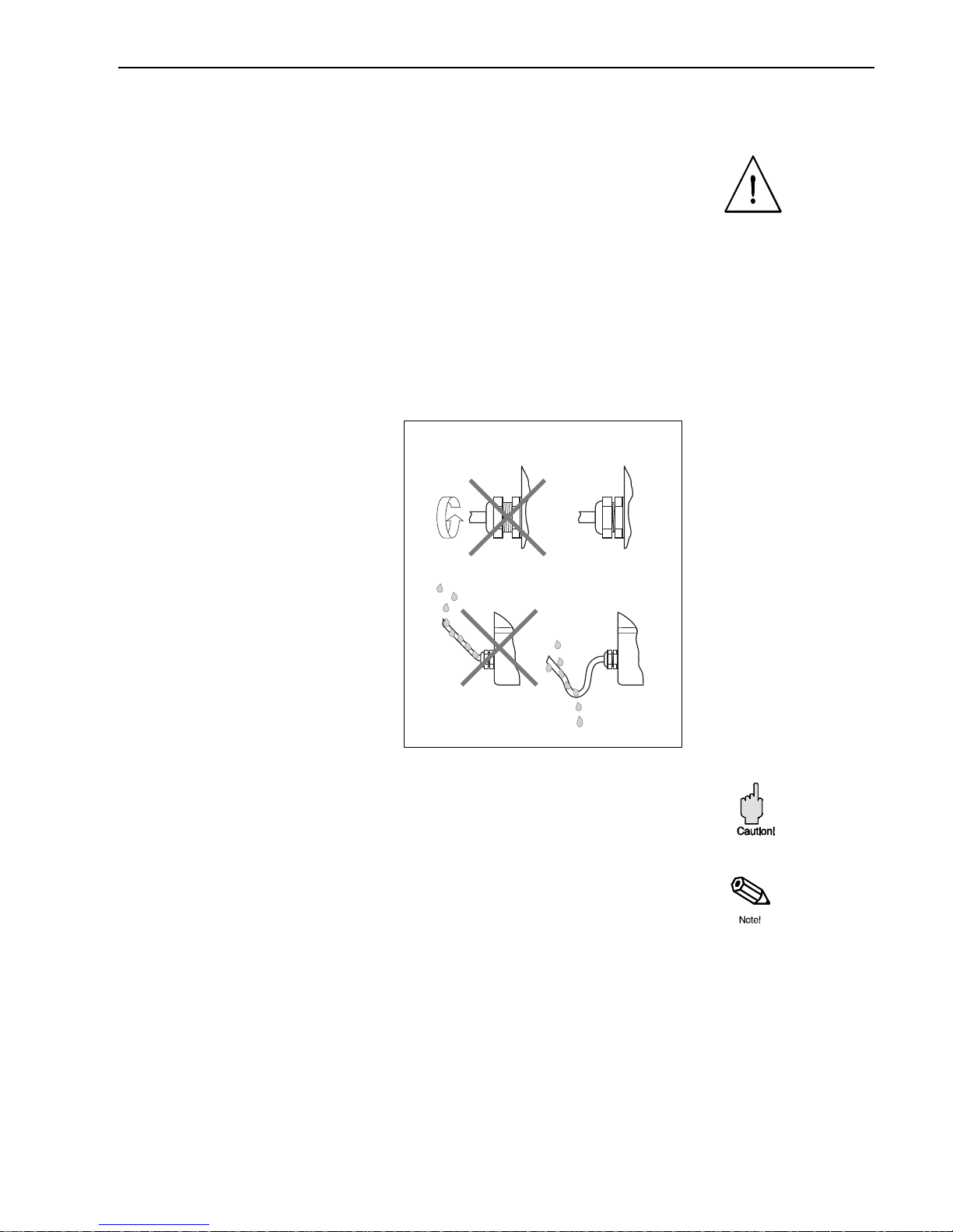
• Tighten the cable entry (see Fig. 5).
• Loop the cable before inserting. This
prevents moisture from penetrating
the cable entry (see Fig. 5).
• Any cable entries not used must be
stopped with a screw plug.
• The protective grommet must not be
removed from the cable entry.
Caution!
The screws of the Promag sensor housing must not be released, otherwise the
guarantee for the type of protection expires.
Note!
The sensors Promag A, D and F can optionally be supplied with the type of protection
IP 68 (permanently under water to a depth of 3 m). In this case the transmitter (IP 67)
has to be mounted remote from the sensor.
Temperature ranges
• The maximum permissible ambient and medium temperatures must be adhered to
(see page 63, 66).
• When installed outdoors, specially in countries with high ambient temperatures,
a weatherproof hood should be provided as protection against direct solar
radiation.
Warning!
ba008y05
Fig. 5
Promag 30 3. Mounting and Installation
Endress+Hauser 13
Page 14
3.2 Transport instructions for Promag from > DN 350 / 14"
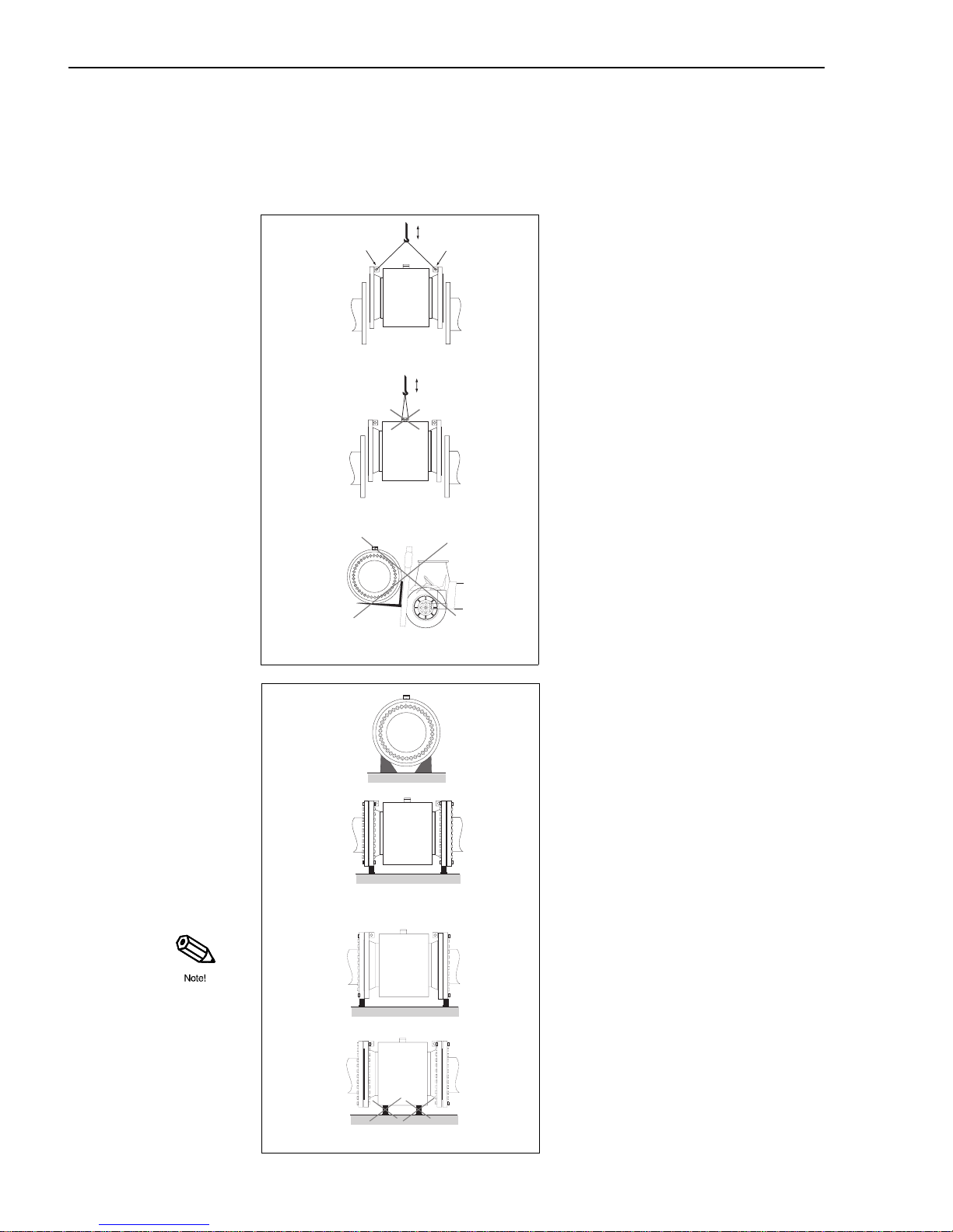
The pipe lining on the flanges is protected by disks to prevent damage when
transporting to the installation point. These are to be removed before installation.
The instruments are to be transported in the containers they are delivered in.
Transporting to the measuring point
• The grips on the flange must be used
for lifting out and mounting the sensor
in the piping.
• The sensor should not be lifted by the
connection housing.
• The sensor should not be lifted by the
sheet casing using a forklift truck.
This can buckle the casing and
damage the internal magnetic coils.
Base of the sensor
The sensor should stand on a base
which is sufficiently strong to withstand
its weight.
Note!
The sensor must not be supported by
the sheet casing! This can buckle the
casing and damage the internal
magnetic coils.
ba008y60
ba008y61
ba008y62
Fig. 6
ba008y63
ba008y64
Fig. 7
3. Mounting and Installation Promag 30
14 Endress+Hauser
Page 15
3.3 Mounting Instructions
Please pay attention to the following instructions, in order that you may measure
correctly and avoid damage to the equipment.
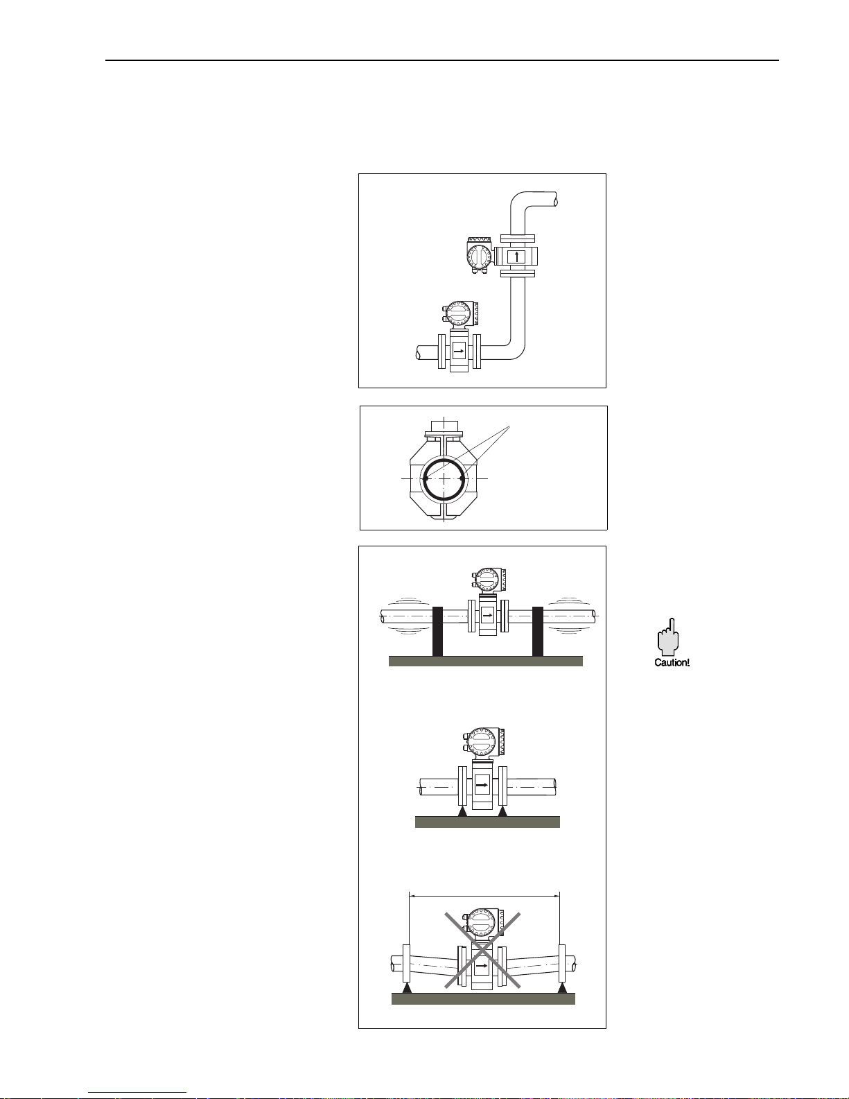
Mounting position (any)
a) Vertical mounting:
Optimal, with the flow upwards.
Entrained solid particles sink and
lighter fatty elements in the
stationary medium rise away from
the electrodes.
b) Horizontal mounting:
The axis of the electrodes must
be horizontal, thus preventing brief
insulation of the electrodes by
entrained air bubbles.
Electrode axis
The plane in which the electrode axis
lies with regard to the Promag 30
measuring transmitter is identical for
the measuring sensors A, D, F and
Promag H also.
Vibration
Fasten the piping before and after the
sensor.
Caution!
Excessive vibration necessitates
separate mounting of the sensor and
transmitter (see chapter 3.6).
With free runs of piping over 10 m long,
we recommend mechanical supports.
ba008y07
a)
b)
Fig. 8
ba008y06
Measuring
electrodes
Electrode axis
Fig. 9
ba008y08
>10 m
Fig. 10
Promag 30 3. Mounting and Installation
Endress+Hauser 15
Page 16
Inlet and outlet runs
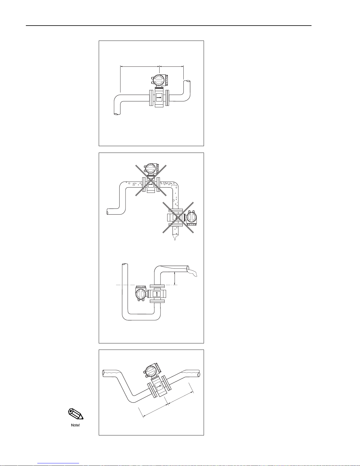
The sensor should be mounted away
from fittings liable to generate
turbulence (e.g. valves, elbows,
T-junctions).
Inlet run: > 3...5 x DN
Outlet run: > 2 x DN
Mounting location
Correct measurement is only possible
when the pipe is full. Consequently the
following locations should be avoided:
• No installation at the highest point
(air accumulation).
• No installation immediately before an
open pipe outlet in a downward line.
The installation shown in Fig. 12,
however, permits such a location.
Partly filled pipes
For inclines a mounting similar to a drain
should be adopted. Do not mount at the
lowest point (risk of solids collecting).
Added security is offered by Empty Pipe
Detection (EPD). This option has an
extra electrode in the measuring pipe
(standard with Promag F sensor).
Note!
Here, too, the inlet and outlet lengths
should be maintained.
DN = pipe diameter
> 3...5 x DN > 2 x DN
ba008y09
Fig. 11
ba008y10
h > 2 x DN
Fig. 12
> 3...5 x DN
> 2 x DN
ba008y11
Fig. 13
3. Mounting and Installation Promag 30
16 Endress+Hauser
Page 17
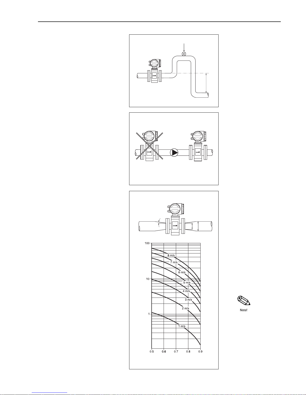
Downward pipe (> 5 m)
With the suggested installation opposite
(siphon, vent valve after the sensor) no
partial vacuum is created with such a
downward pipe > 5 m long.
Installation of pumps
If possible avoid mounting the sensor on
the suction side of the pump (danger of
vacuum!). Information on the resistance
to vacuum of the measuring pipe lining
can be found on page 62.
Adaptor pieces
The sensor can also be mounted in a
pipe with a larger nominal diameter
when suitable adaptors (reducers and
expanders) to DIN 28545 are fitted. The
resultant increase in the rate of flow
increases the accuracy of measurement
with slowly flowing fluids.
The adjacent nomogram can be used to
determine the pressure loss caused.
Procedure:
1. Determine the ratio of the diameters
d/D.
2. From the nomogram read off the
pressure loss at the flow velocity and
d/D ratio.
Note!
The nomogram applies to fluids with a
viscosity similar to that of water.
Vent valve
ba008y12
>5 m
Fig. 14
ba008y13
Fig. 15
max. 8°
dD
ba008y14
Pressure loss in [mbar]
Diameter ratio d/D
Fig. 16
Promag 30 3. Mounting and Installation
Endress+Hauser 17
Page 18
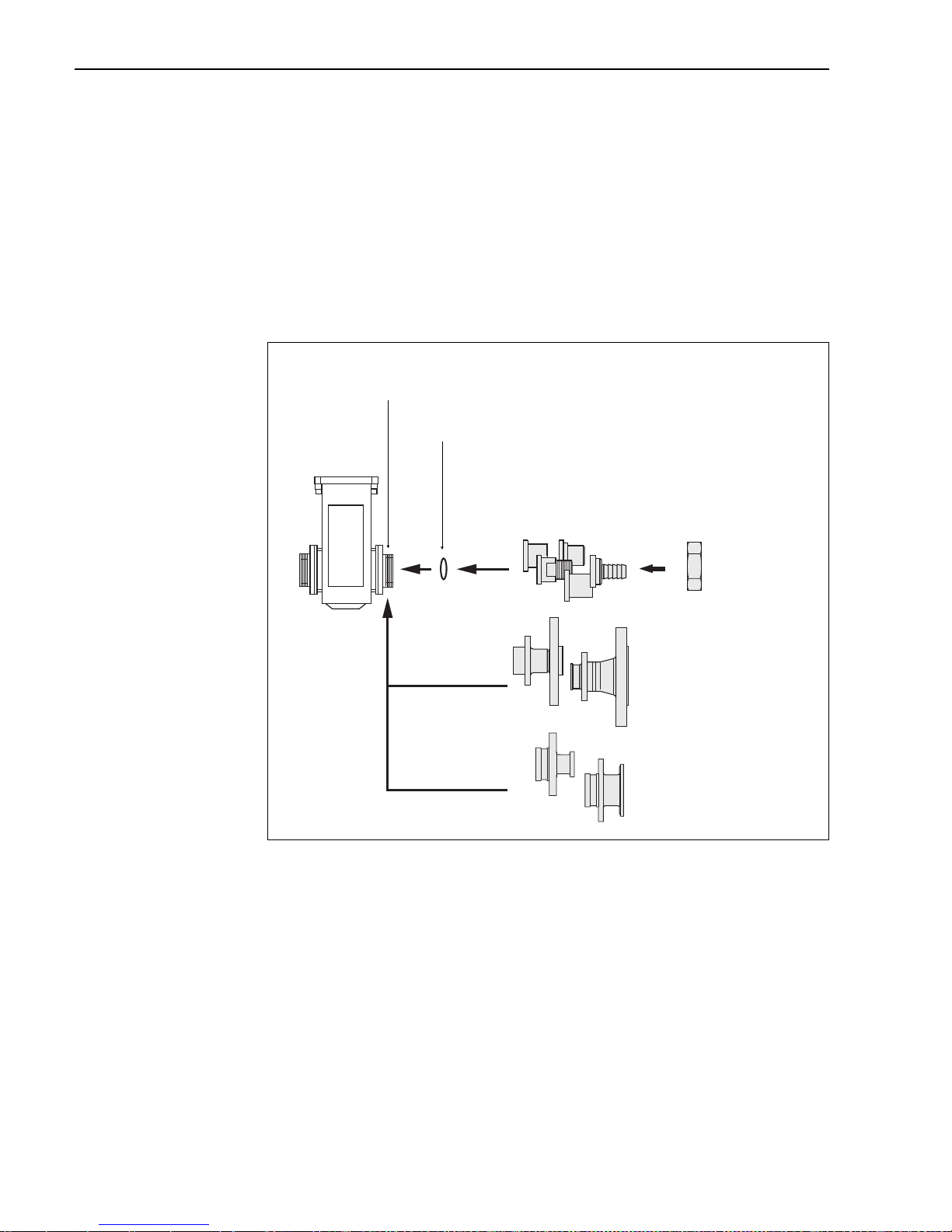
3.4 Mounting the sensor
Mounting Promag 30 A
Length and dimensions
See chapter 7.1 “Dimensions and weights”.
Mounting
The inserted parts are
• screwed on to the 1" stub with a skirted nut.
• mounted instead of the 1" threaded stub.
Screw tightening torques and gaskets
When screwing on the inserted parts the O-ring or the flat gasket is pressed
completely into the sealing groove of the stub. The skirted nut thereby experiences a
fixed stop.
3. Mounting and Installation
Sensor 1" threaded stub (ISO 228):
not required with flange joints
O-ring of Viton or Kalrez or silicone flat gasket
(aseptic) version
Nominal
diameters:
DN 2...25
ba008y15
Internal thread, external thread, PVC adhesive
coupling, hose connection and welded nipples,
are screwed on with a skirted nut
Tri-clamp
®
connection are
fitted instead of the
threaded stub.
Flange joints
(stainless steel 1.4404/316L,
PVDF) are fitted instead of the
threaded stub
Fig. 17
3. Mounting and Installation Promag 30
18 Endress+Hauser
Page 19
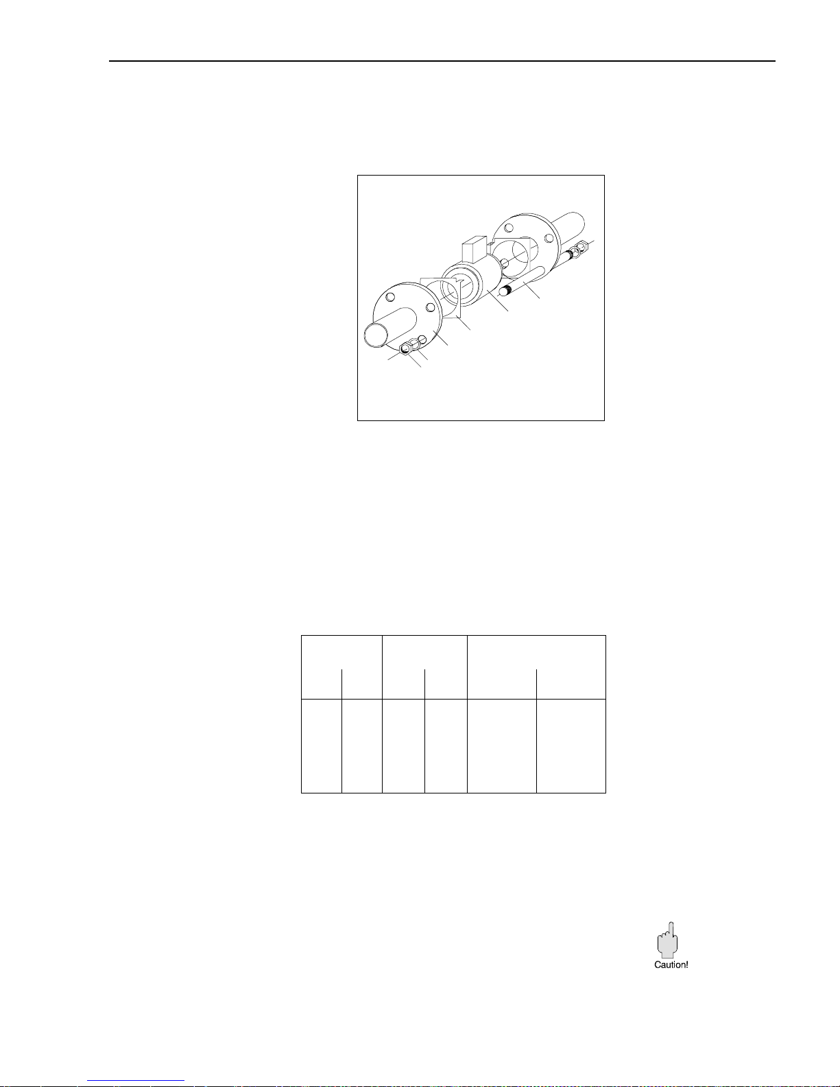
Mounting Promag 30 D
Length and dimensions
See chapter 7.1 “Dimensions and weights”.
Mounting
Mounting of the wafer is carried out with
the aid of a mounting set which
consists of:
• Tie rods
• Centering discs
(not needed with DN 32 and 65)
• Nuts
• Washers
When hard rubber liner is used,
additional flat gaskets are needed.
Procedure:
1. Mount the three or correspondingly more tie rods with washers, including two
gaskets, on both pipe flanges. Pay attention to the instructions given below
regarding gaskets.
2. Push the two centering discs on to the measuring pipe.
3. Now fit the sensor together with the centering discs between the already mounted
tie rods.
4. Mount the remaining tie rods, but do not tighten up the hex nuts yet.
5. Turn the centering discs so that the studs can be driven centrally outwards.
6. Now tighten up the hex nuts.
Screw tightening torques
• The listed tightening
torques apply to greased
threads.
• Screws tightened up too
tightly deform the sealing
surface (pay special
attention with soft rubber
lining).
Gaskets
• With soft rubber/Teflon (PTFE) linings a flange gasket can be dispensed with.
• With soft rubber linings the mating flange should have a thin film of sealing grease
applied.
• Use a gasket as per DIN 2690.
Caution!
Do not use sealing media that are electrically conductive, e.g. graphite. On the inside
of the measuring pipe this could result in an electrically conductive layer forming
which would short-circuit the measuring signal.
Tie rod
Promag D
Centering disc
Flange
Washer
Nut
ba008y16
Fig. 18
DN Pressure stage Max. tightening torque
[Nm]
DIN
[mm]
ANSI
[inch]
DIN
[bar]
ANSI
[Ibs]
Hard rubber
Teflon (PTFE)
Soft rubber
(EPDM)
25
32
40
50
65
80
100
1"
-
1
1
/2"
2"
3"
4"
PN 40 Class
150
35
55
70
85
65
75
120
15
20
30
30
30
35
65
Promag 30 3. Mounting and Installation
Endress+Hauser 19
Page 20
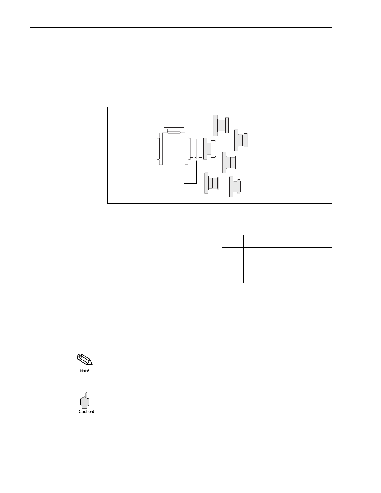
Mounting Promag 30 H
Length and dimensions
See chapter 7.1 “Dimensions and weights”.
Mounting
The various process connectors are fastened to the sensor with 4 or 6 screws. As a
rule, the promag H sensor is supplied with works-monted process connectors.
When mounting the process connectors,
please make sure that the packing is
free of dirt and correctly centered.
The screws have to be tightened.
The process connector forms a metal
connection with the sensor, so the
packing is not compressed.
Welding the sensor into the pipework
If the sensor is directly welded into the pipework, we recommend that you:
1. Fasten the Promag H sensor with some welding points into the pipe;
2. Loosen the screws at the process-connector flange and remove the sensor from the
pipe; make sure that the gasket is also removed from the process connector;
3. Weld the process connector into the pipe.
4. Once again install the sensor into the pipe; make sure everything is clean and
the gasket is correctly positioned.
Note!
If the welding process is correctly executed, the gasket will not be damaged by the
heat, even when mounted. Nevertheless, we recommend you remove the sensor and
gasket first.
For the mounting, the pipe has to be opened by about 4 mm.
Caution!
Please note that the grounding of the welding set does not occur by way of the
Promag 30 H (sensor or transmitter). If you fail to observe this, the electronics might
be destroyed.
Process connections
Welded hex nipple, Tri-Clamp®,
DIN 11851, ISO 2852, ISO 2853 or
SMS are fastened to the sensor
with screws (already mounted
when delivered)
Flat gasket made of
Silicone or EPDM
ba008y99
Promag H
Fig. 19
DN Pressure
stage
Max. tightening
torque
[Nm]
DIN
[mm]
ANSI
[inch]
25
40
50
65
80
100
1"
1
1
/2"
2"
2
1
/2"
3"
4"
PN 16
10
10
25
25
88
88
3. Mounting and Installation Promag 30
20 Endress+Hauser
Page 21
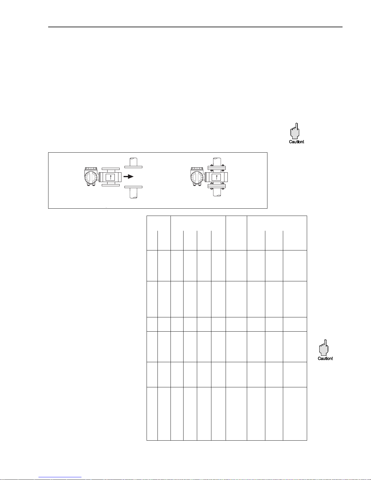
Mounting Promag 30 F
Lengths and dimensions
See chapter 7.1 “Dimensions and weights”
Mounting
The sensor is mounted between the flanges of the pipe (see Fig. 20). Since the lining
of the measuring pipe is drawn on over the sensor flange, it performs the sealing
function at the same time.
Caution!
The Teflon (PTFE)-lined measuring pipe of the Promag F is fitted with protective discs
to guard the liner which is turned over the flanges. These discs may only be removed
just before mounting the sensor, thereby making sure that the liner is not damaged at
the flange or removed (during storage these discs must remain in position).
Screw tightening torques
• The listed tightening torques
apply to greased threads.
• Screws tightened up too tightly
deform the sealing surface (pay
special attention with soft rubber
lining).
Gaskets
• With soft rubber/Teflon (PTFE)
linings a flange gasket can be
dispensed with.
• With soft rubber linings the
mating flange should have a thin
film of sealing grease applied.
• Use a gasket as per DIN 2690.
Caution!
Do not use sealing media that is
electrically conductive, e.g.
graphite. On the inside of the
measuring pipe this could result in
an electrically conductive layer
forming which would short-circuit
the measuring signal.
DN Pressure stages Screws Max. tightening torque
[Nm]
DIN
[mm]
ANSI
[inch]
DIN
[bar]
ANSI
[Ibs]
AWWA JIS Hard
rubber
Soft
rubber
(EPDM)
Teflon
(PTFE)
15
25
32
40
50
1
/2"
1"
-
1
1
/2"
2"
PN40Class
150
-
20K
20K
20K
20K
10K
4 x M 12
4 x M 12
4 x M 16
4 x M 16
4 x M 16
25
40
50
64
5
8
11
15
15
33
53
67
84
65
80
100
125
150
200
3"
4"
6"
8"
PN16Class
150
-
10K
10K
10K
10K
10K
10K
4 x M 16
8 x M 16
8 x M 16
8 x M 16
8 x M 20
8 x M 20
87
53
65
80
110
108
22
14
22
30
48
53
114
70
85
103
140
137
250
300
10"
12"PN10
Class
150
-10K
10K
12 x M 20
12 x M 20
104
1192939
139
159
350
400
500
600
14"
16"
18"
20"
24"
PN
10/16
Class
150
--
16 x M 20
16 x M 24
20 x M 24
20 x M 24
20 x M 27
141/193
191/245
170/251
197/347
261/529
39/79
59/111
58/111
70/152
107/236
188/258
255/326
227/335
262/463
348/706
700
800
900
1000
28"
30"
32"
36"
PN
10/16
- ClassD-
24 x M 27
24 x M 30
28 x M 30
28 x M 33
312/355
417/471
399/451
513/644
122/235
173/330
183/349
245/470
-
-
-
-
1200
-
1400
-
1600
-
1800
-
2000
48"
54"
-
60"
66"
72"
78"
-
PN6- ClassD-
32 x M 36
36 x M 39
36 x M 39
40 x M 45
40 x M 45
44 x M 45
44 x M 45
48 x M 45
48 x M 45
720
840
840
1217
1217
1238
1238
1347
1347
328
432
432
592
592
667
667
749
749
-
-
-
-
-
-
-
-
-
ba008y17
Fig. 20
Promag 30 3. Mounting and Installation
Endress+Hauser 21
Page 22
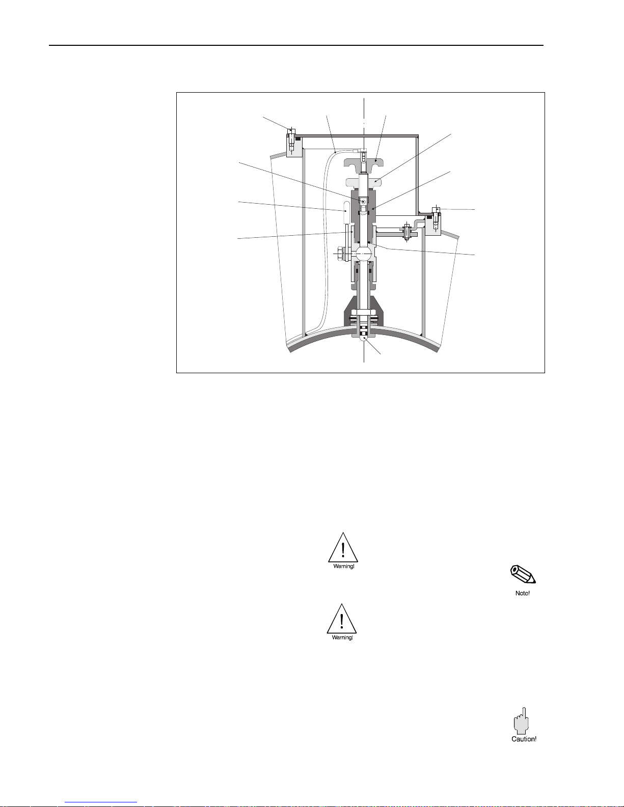
Replacement measuring electrodes
The Promag F Type DN 350...DN 2000 is available with replacement electrodes.
This version enables the measuring electrodes to be cleaned or replaced under process conditions.
Replacing an electrodes is carried out as follows:
Dismantling the electrode:
1. Loosen the Allen screws (a) of the cap/cover.
2. Unscrew the electrode cable (c) attached to the
rotary arm (b).
3. Undo the knurled nut (d) by hand. This nut is
used as a counter nut.
4. Remove the electrode (e) using the rotary arm
(b). This can now be taken out from the holder
(g) as far as the stop allows.
Warning!
The electrode can spring back to the
stop. Keep pressing against it
while loosening.
5. Close the shut-off valve (f) after the electrode has
been taken out as far as the stop.
Warning!
Do not attempt to open the shut-off
valve. Keeping it shut prevents
medium from escaping.
6. Unscrew the entire electrode along with the holding cylinder (g).
7. Remove the pins (h) below the rotary arm.
8. Replace electrode with a new one.
A set of new electrodes can be ordered from
E+H.
Assembling the electrode:
1. Slide the new electrode (e) through the holding
cylinder (g) from below.
Gaskets at the tip of the electrode must be in
place and clean.
2. Connect the rotary arm (b) and electrodes together using the pins (h). Ensure that the small coil
spring is in place.
3. Pull back the electrode as far as possible so that
the tip does not protrude out from the holding cylinder (g).
4. Screw the holding cylinder onto the shut-off unit
(I) and tighten by hand.
Note!
Gasket (j) on the holding cylinder
must be in place and clean.
5. Open the shut-off value (f) and screw in the
electrode using the rotary arm (b). Pull the
electrode on by hand.
6. Screw the knurled nut (d) onto the holding cylinder in order to clamp the electrode tight.
7. Secure the electrode cable (c) to the rotary arm
using the Allen screw.
Caution!
Ensure that the Allen screw of the
electrode cable is tight. A close
electrical contact cannot otherwise
be guaranteed and this can lead to
measurement errors.
ba008y67
a
h
f
i
b
d
g
a
j
e
c
• left side:
Type DN 1350...2000
• right side:
Type DN 350...1200
Fig. 21
3. Mounting and Installation Promag 30
22 Endress+Hauser
Page 23
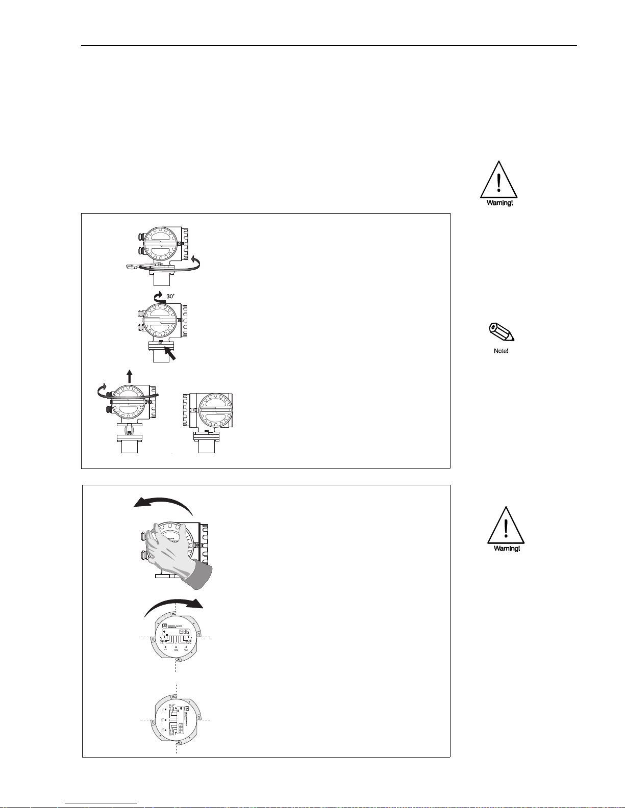
3.5 Turning the transmitter housing and local display
(compact version)
In the compact version the transmitter housing and the local display can be rotated in
steps of 90° relative to the sensor. This enables the unit to be adapted to suit the
various mounting positions in the pipe.
Warning!
For instruments with EEx d/de or FM/CSA Cl. I Div. I approval the procedure for
rotating the instrument is different than that described here and is given in the
Ex supplement to this manual.
Turning the transmitter housing
1. Loosen the two fixing screws of the transmitter bayonet catch (appr. 2 turns).
2. Turn the bayonet catch of the transmitter as
far as the screw slits.
3. Lift the transmitter housing to the stop.
Note!
During servicing (and only then) the transmitter housing can be separated from the sensor. To do this the corresponding marking
notches on the side of the bayonet flanges
should be brought into alignment. Do not damage the cable to the sensor when lifting the
transmitter housing.
4. Turn the transmitter housing into the desired
position. Engage the bayonet catch and retighten the two screws.
ba008y18
Fig. 22
Turning the local display
Warning!
Danger from electric shock. Switch off the
power supply, before unscrew the cover of
electronics area.
1. Loosen the safety grip of the cover of the
electronics area. Loosen the screw with a 3
mm Allen key.
2. Unscrew the cover of the electronics area of
the transmitter housing.
3. Unscrew the two Phillips screws which fasten the display module.
4. Rotate the display module to the required position.
5. Securely tighten the Phillips screws.
6. Replace and screw down securely the cover
of the electronics area of the transmitter housing.
7. Replace and tighten the safety grip.
ba008y19
Fig. 23
Promag 30 3. Mounting and Installation
Endress+Hauser 23
Page 24
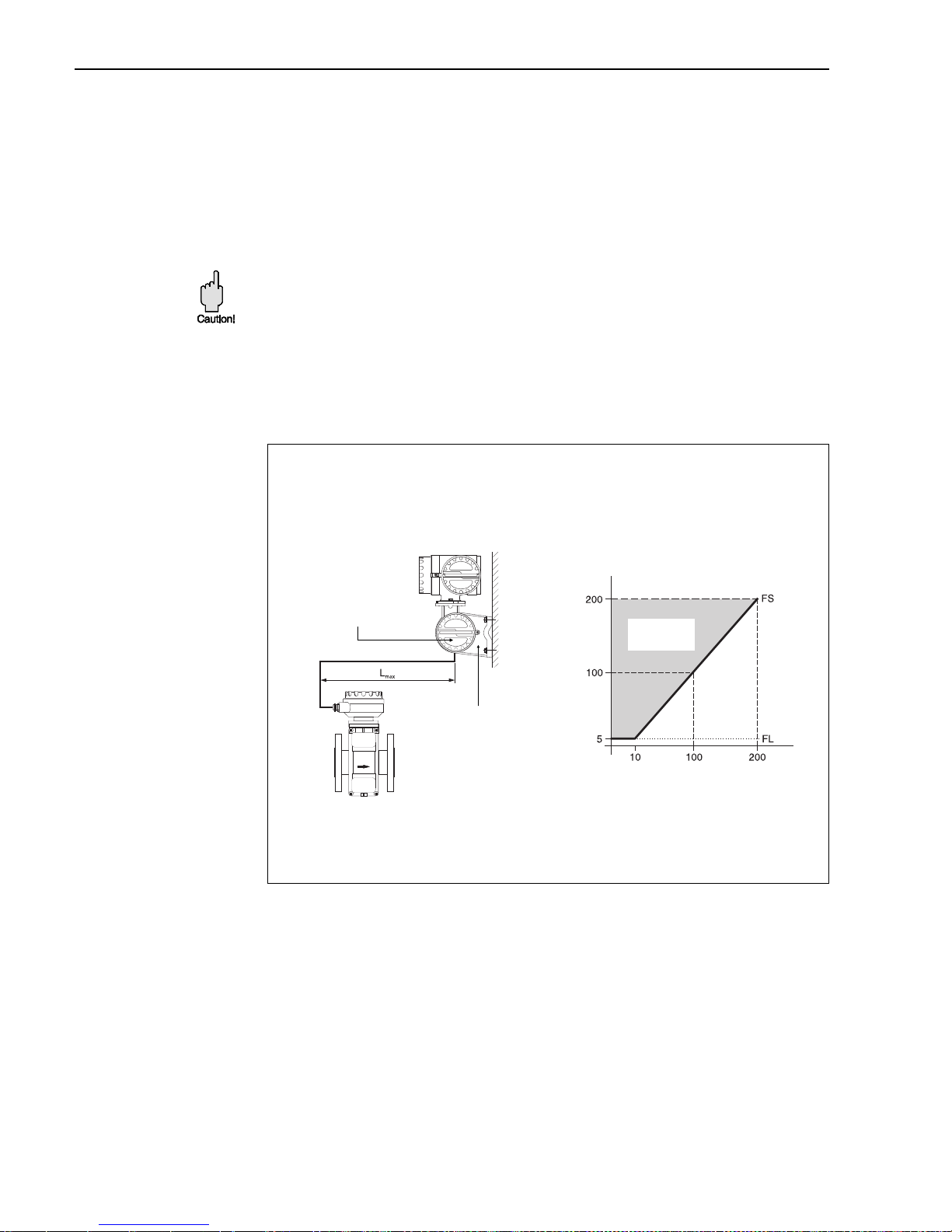
3.6 Mounting the transmitter (remote-mounted version)
It is necessary to mount the transmitter remote from the sensor when:
• Accessibility is difficult
• Space is restricted
• Extreme medium and ambient temperatures prevail
(for temperature ranges see page 63)
• Severe vibration (>2 g/2 h per day; 10...100 Hz)
Caution!
• The permissible length of cable L
max
between the sensor and the transmitter at a
distance of >10 m is governed by the conductivity of the medium (Fig. 24).
• Fix the cable run or lay it in conduit. When the conductivity of the medium is low,
cable movements can cause serious changes in capacitance and thereby falsify
the measuring signal.
• Do not lay cable in the vicinity of electrical machines or switching elements.
• Pay attention to potential equalization between the transmitter and the sensor.
• Please connect the cable as described on page 27f.
Cable length L
max
Conductivity
[µS/cm]
ba008y20
Transmitter housing
Wiring compartment
connection housing
Wall holder
Length of cable for the remo te-mounted version (FS and FL)
[m]
Permissible
range
Fig. 24
3. Mounting and Installation Promag 30
24 Endress+Hauser
Page 25
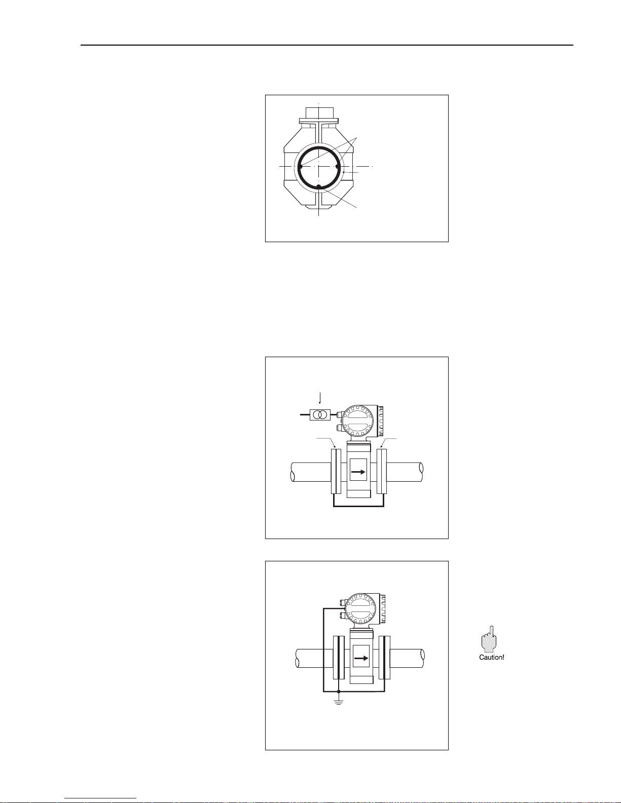
3.7 Potential equalisation
The sensor and the medium must have
roughly the same electrical potential to
ensure that measurement is accurate
and no galvanic corrosion takes place
at the electrodes. Normally the
reference electrode in the sensor or the
metal pipe ensures that the potentials
are equalized. With an existing
reference electrode and for media
carried in earthed metal piping it is
therefore sufficient to connect the
earthing terminal of the Promag 30
transmitter housing to the potential
equalizing line.
With the remote-mounted version this connection is made at the earth terminal of the
connection housing (transmitter). Sensors Promag A and D are always fitted with a
reference electrode, in Promag F it is depending on the electrode material optional.
There is no reference electrode with Promag H as there is always a metallic
connection to the product. Fig. 25 shows the reference electrode in the sensor
Promag F.
Potential equalisation for some special cases is described below:
Potential equalisation for lined
pipes with cathodic protection
When the medium cannot be earthed
for operational reasons, the measuring
unit must be installed that it is
potential-free (Fig. 26).
Please pay attention to national
regulations regarding potential-free
installation (e.g. VDE 0100).
It is also important to ensure that the
mounting material used does not result
in a conductive bond with the
measuring unit and that the material can
withstand the tightening torque used.
Plastic or lined piping
This arrangement (Fig. 27) is needed if
there is no reference electrode present
or the medium has to be earthed on
account of equalizing currents.
Caution!
Make sure the earthing discs are
corrosion-resistant.
Measuring electrodes
Measuring pipe
Reference electrode
ba008y22
Fig. 25
Isolating transformer
Electrically
insulated
Electrically
insulated
ba008y23
6 mm2 Cu
Supply
Fig. 26
Earthing discs: appr. 3 mm thick
ba008y24
6 mm2 Cu
Fig. 27
Promag 30 3. Mounting and Installation
Endress+Hauser 25
Page 26
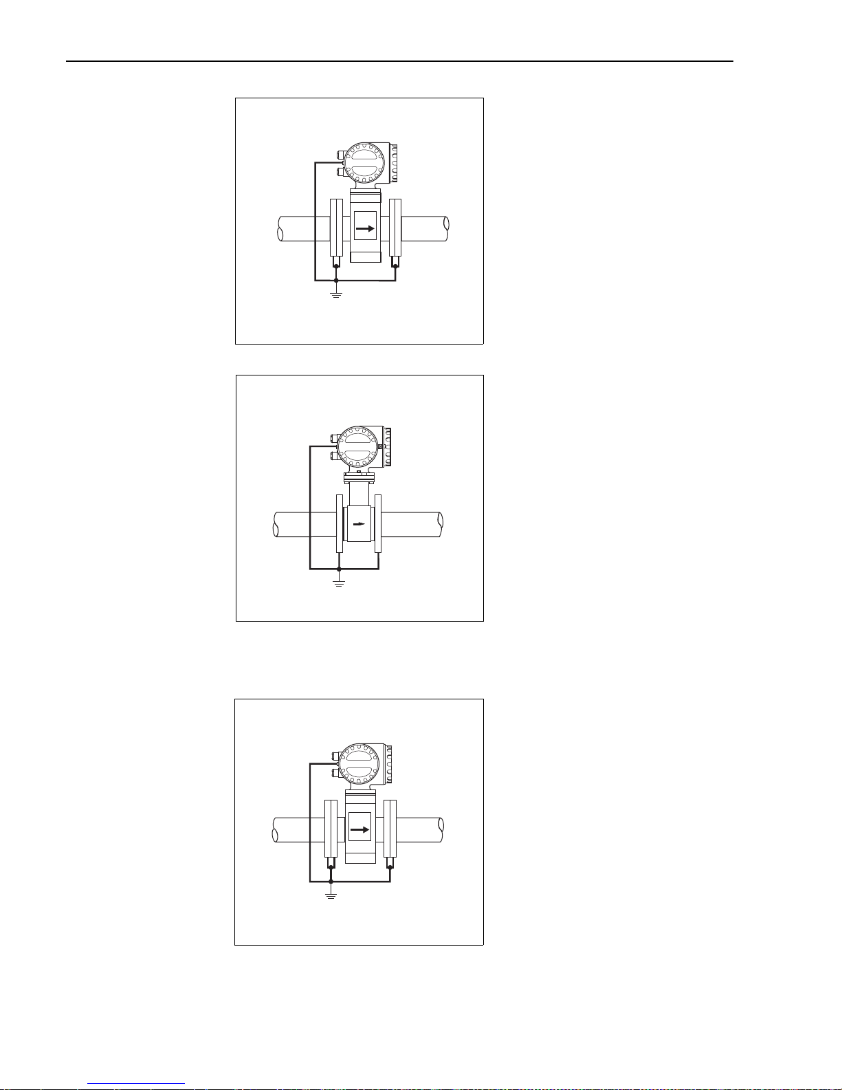
Equalising currents in unearthed metal pipes
The medium may be earthed.
Make the electrical connection from
flange to flange and to the measuring
unit (Fig. 28, 29).
3.8 Earthing in an area with severe interference
In order to make the most of the
electromagnetic compatibility (EMC) of
the Promag 30, it is advisable to provide
two flange-to-flange links and to
connect them jointly with the transmitter
housing to earth potential.
Example: Promag 30 F
ba008y25
6 mm2 Cu
Fig. 28
Example: Promag 30 D
ba008y26
6 mm2 Cu
Fig. 29
ba008y27
6 mm2 Cu
Fig. 30
3. Mounting and Installation Promag 30
26 Endress+Hauser
Page 27
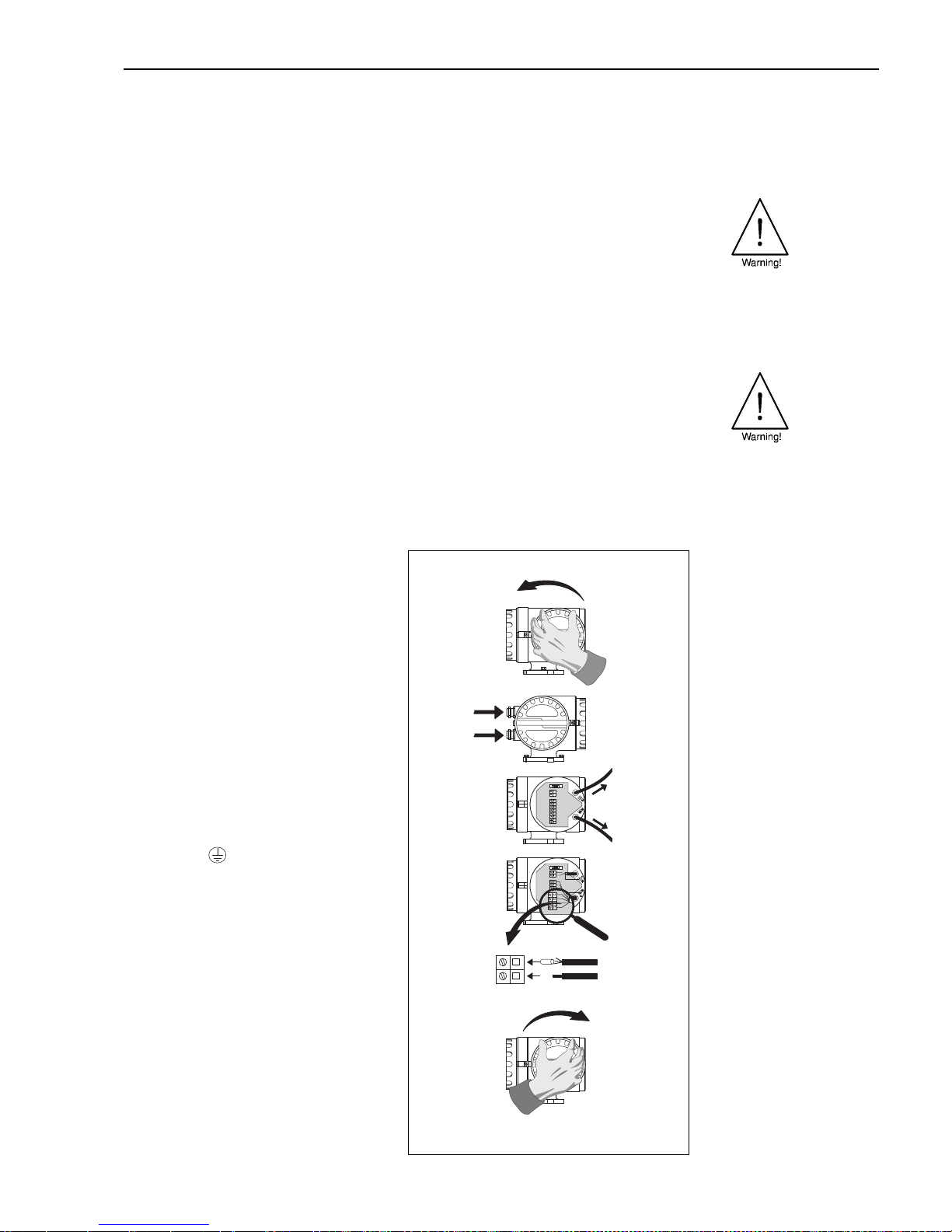
4. Electrical Connection
4.1 General information
Warning!
• Please note the information in section 3.1 on maintenance of the type of protection
IP 67.
• When connecting explosion protected versions, refer to the corresponding
information and connection diagrams in the Ex supplement to this operating manual.
Your E+H representative will be pleased to provide you with more information.
4.2 Connection to the transmitter
Warning!
• Risk of electric shock. Install or wire the unit when it is not alive. Failure to comply
can also result in damage to electronic components.
• Join the protective conductor to the earth terminal of the housing before the supply
voltage is switched on.
• Compare the data on the nameplate with the local mains voltage and frequency.
Also pay attention to the national rules for installation.
1. Release the safety grip of the screw
cover of the terminal compartment
using a 3-mm Allen key. Then
unscrew the cover from the terminal
compartment of the transmitter.
2. Push the supply cable and signal
cable in through the appropriate
cable entries.
3. Make the connection in accordance
with the wiring diagrams (see also
wiring diagram in the screw cover):
• The supply voltage is connected to
terminals 1 (L1 oder L+), and 2
(N oder L-) and the earthing
terminal .
• Fine-wire leads: max. 4 mm
2
; put
sleeves on the end of the cores.
Single-core lead: max. 6 mm
2
.
4. Having made the connection, screw
the cover up tight again on the
transmitter housing. Tighten the Allen
screw of the safety grip thoroughly.
ba008y28
4 mm
2
6 mm
2
Supply
cable
Signal
cable
➀
➁
➂
➃
Fig. 31
Promag 30 4. Electrical Connection
Endress+Hauser 27
Page 28
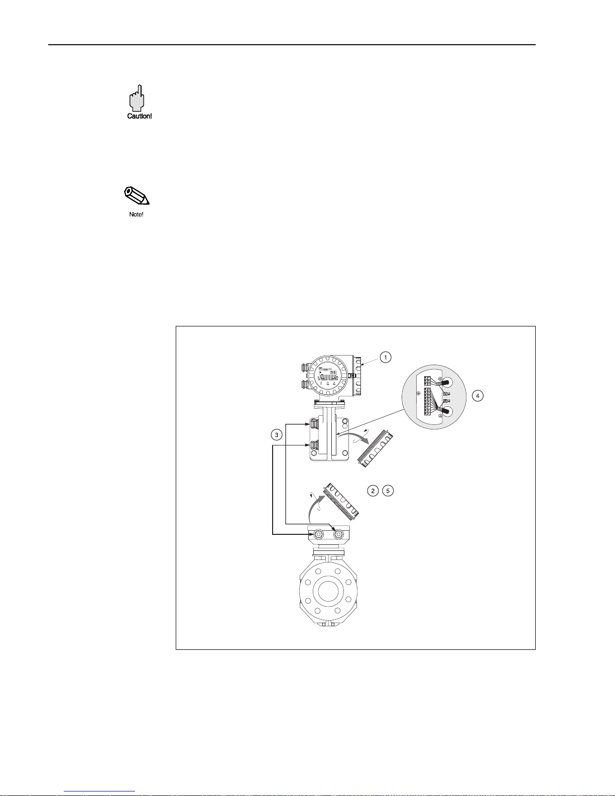
4.3 Connection of the remote version
Caution!
Only connect or disconnect the coil-current cable when the supply is switched off.
1. The connection to the terminal compartment is made as described for the
compact version (see section 4.2).
2. Open the covers of the connection housing of the sensor and transmitter by
unscrewing the screw cover or the four Phillips screws.
Note!
The terminals of Promag A are situated inside its housing.
3. Push both cables (signal and coil-current cable) in through the appropriate cable
entries.
4. Make the connection between the sensor and transmitter in accordance with the
wiring diagrams.
5. Tighten the cover of the connection housing securely.
ba008y29
Transmitter
Sensor
Fig. 32
4. Electrical Connection Promag 30
28 Endress+Hauser
Page 29
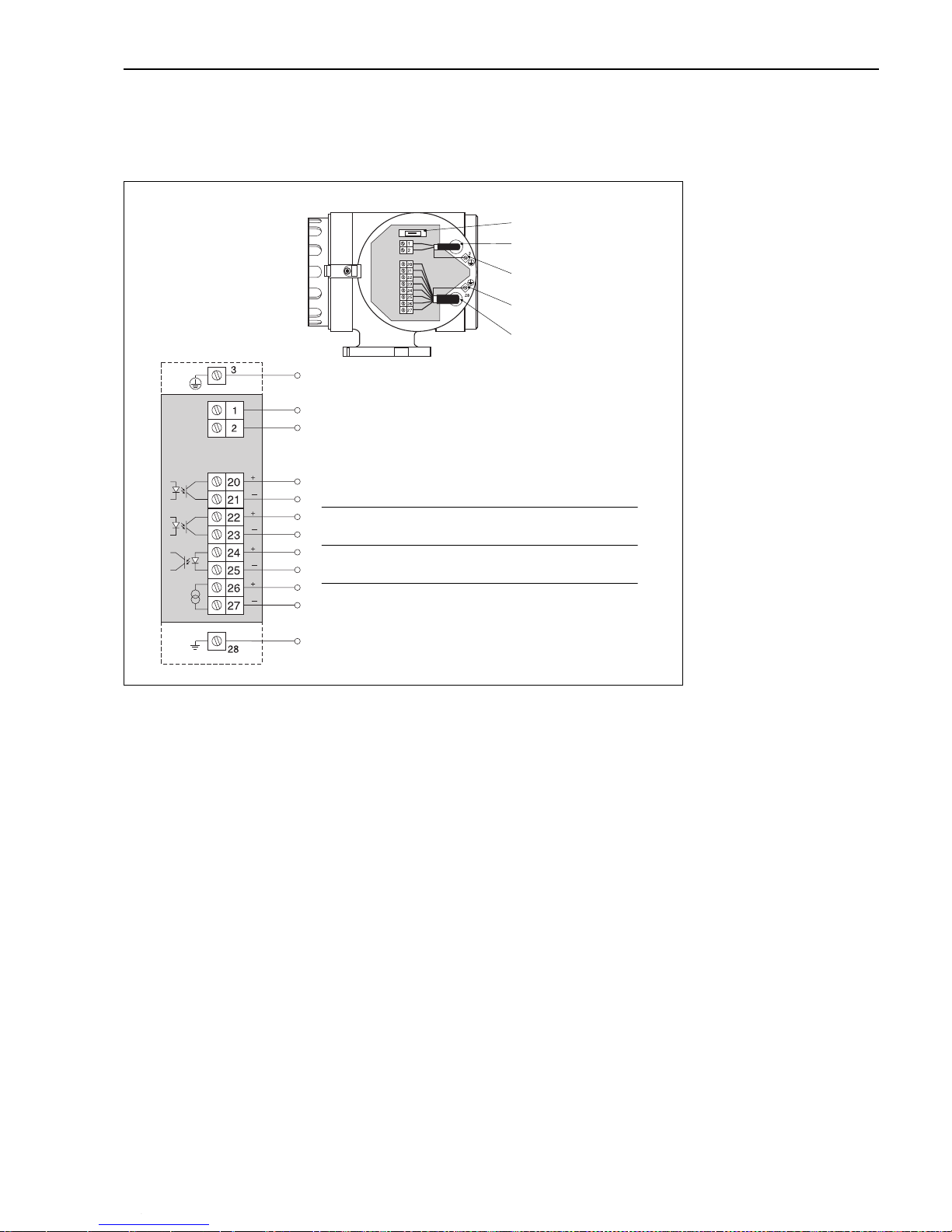
4.4 Wiring diagrams
Electrical connection: supply, inputs and outputs
Earth terminal (ground wire)
L1
}
for AC
L+
}
for DC supply
NL-
Pulse/frequency output
(passive)
Status output (passive)
Auxiliary input
Current output (active)
Earth terminal (screen of signal cable)
f
max
= 400 Hz
max. 30 V/250 mA
max. 30 V/250 mA
⇒
System/process fault indication
⇒
Flow direction
3...30 V DC, R
i
= 1.8 k
Ω
•
Measured value suppression
•
External reset for totaliser
0/4...20 mA
R
L
< 700
Ω
Fuse
Supply cable
Earth terminal for
ground wire
Earth terminal for
cable screen
Signal cable
ba008y30
Fig. 33
Promag 30 4. Electrical Connection
Endress+Hauser 29
Page 30
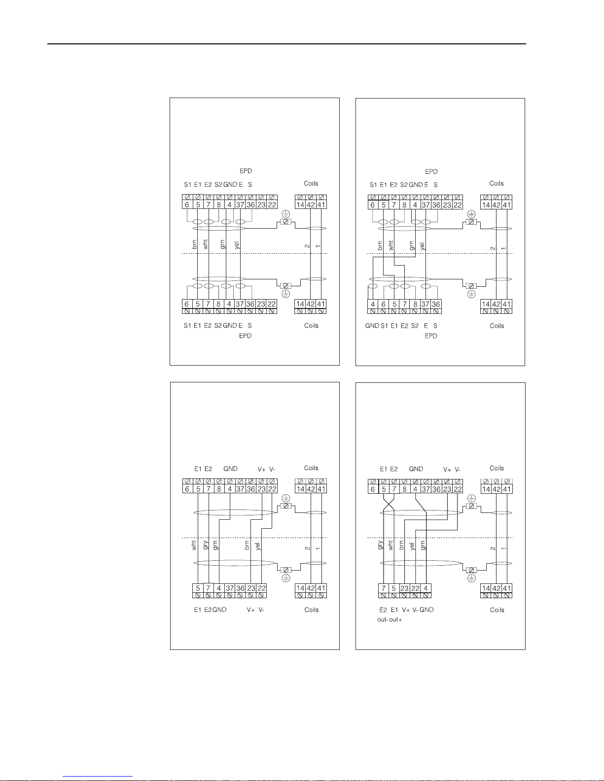
Remote-mounted version (FS/FL): Connection between sensor and transmitter
Promag 30 D, H and F
(FS version)
Transmitter
Promag 30 A
(FS version)
Transmitter
Promag 30 D, H and F
(FL version)
Transmitter
Promag 30 A
(FL version)
Transmitter
Sensor
Sensor
Sensor
Sensor
ba008e66
Fig. 34
4. Electrical Connection Promag 30
30 Endress+Hauser
Page 31

4.5 Cable specifications
Cable specification for remote-mounted version (FS)
Coil cable: 2 x 0.75 mm
2
PVC cable with common screen
Conductor resistance: ≤37 Ω/km
Capacitance: core/core, screen earthed ≤120 pF/m
Permanent temperatur: -20°C...70°C
Signal cable: 3 x 0.38 mm2 PVC cable with common screen and
separately screened cores.
Conductor resistance: ≤50 Ω/km
Capacitance: core/screen ≤420 pF/m
Permanent operation temperatur: -20°C...70°C
Cable specification for remote-mounted version (FL)
Coil cable: 2 x 0.75 mm
2
PVC cable with common screen
Conductor resistance: ≤37 Ω/km
Capacitance: core/core, screen earthed ≤120 pF/m
Permanent operation temperatur: -20°C...70°C
Signal cable: 5 x 0.5 mm2 PVC cable with common screen
Conductor resistance: ≤37 Ω/km
Capacitance: core/core, screen earthed ≤120 pF/m
Permanent operation temperatur: -20°C...70°C
Cable specifications for use in areas with severe electrical interference
The Promag 30 measuring equipment fulfils all general requirements for
electromagnetic compatibility (EMC) according to EN 50081 Part 1 and 2 /
EN 50082 Part 1 and 2 when installed in accordance with the NAMUR
recommendations.
Note!
• With the remote-mounted version (FS and FL) the signal and coil cables between
sensor and transmitter must always be screened and earthed at both ends.
This is done at the earth terminals inside the connection housing of sensor and
transmitter (see page 30).
• The cable must be resistant to an ambient temperature of max. +80 °C if the
Promag H is operated at a process temperature of +150 °C.
Promag 30 4. Electrical Connection
Endress+Hauser 31
Page 32

Promag 30
32 Endress+Hauser
Page 33

5. Operation and Commissioning
5.1 Instrument Functions
With Promag 30, various instrument functions can be activated or deactivated using
miniature switches (see page 37). Explanations on individual instrument functions are
given on the following pages.
➤
Creep suppression
Works setting: Switched on
Switch No. 1: ON
Creep suppression prevents
“false flow” in the lower part of the
measuring range from being
detected (e.g. varying liquid head
at standstill). This enables flows to
be suppressed which should not be
measured or totalled.
Cut-in point
When the velocity of the medium
is less than 0.02 m/s creep
suppression is activated and all
output signals (pulse and analogue
signals) are set to the fall back
value (0/4 mA, logical “0”).
Cut-off point
When the velocity of the medium
again exceeds v = 0.04 m/s, creep
suppression is deactivated.
Nominal diameter Cut-in point Cut-off point
DIN
[mm]
ANSI
[inch]
at v = 0.02 m/s
in [m
3
/h]
at v = 0.04 m/s
in [m3/h]
2
1
/12"
0.0002 0.0005
4
5
/32" 0.0009 0.0018
8
5
/16" 0.004 0.007
15
1
/2" 0.013 0.025
25 1" 0.035 0.071
32 1
1
/4" 0.058 0.116
40 1
1
/2" 0.090 0.181
50 2" 0.141 0.283
65 2
1
/2" 0.239 0.478
80 3" 0.362 0.724
100 4" 0.565 1.131
125 5" 0.884 1.767
150 6" 1.272 2.545
200 8" 2.262 4.524
250 10" 3.534 7.069
300 12" 5.089 10.179
350 14" 6.927 13.854
400 16" 9.048 18.096
450 18" 11.451 22.902
500 20" 14.137 28.274
600 24" 20.358 40.715
700 28" 27.709 55.418
750 30" 31.809 63.617
800 32" 36.191 72.382
900 36" 45.804 91.609
1000 40" 56.549 113.097
1200 48" 81.443 162.860
1350 54" 103.060 206.120
1400 56" 110.836 221.672
1500 60" 127.234 254.468
1600 64" 144.764 289.528
1700 66" 163.426 326.852
1800 72" 183.218 366.436
2000 78" 226.194 452.388
ba008y32
Hysteresis = -50% of creep rate
1
Cut-in point for suppression
2
Cut-off point for suppression
v
Creep rate
suppression
active
suppression
active
Time
Fig. 35
Promag 30 5. Operation and Commissioning
Endress+Hauser 33
Page 34
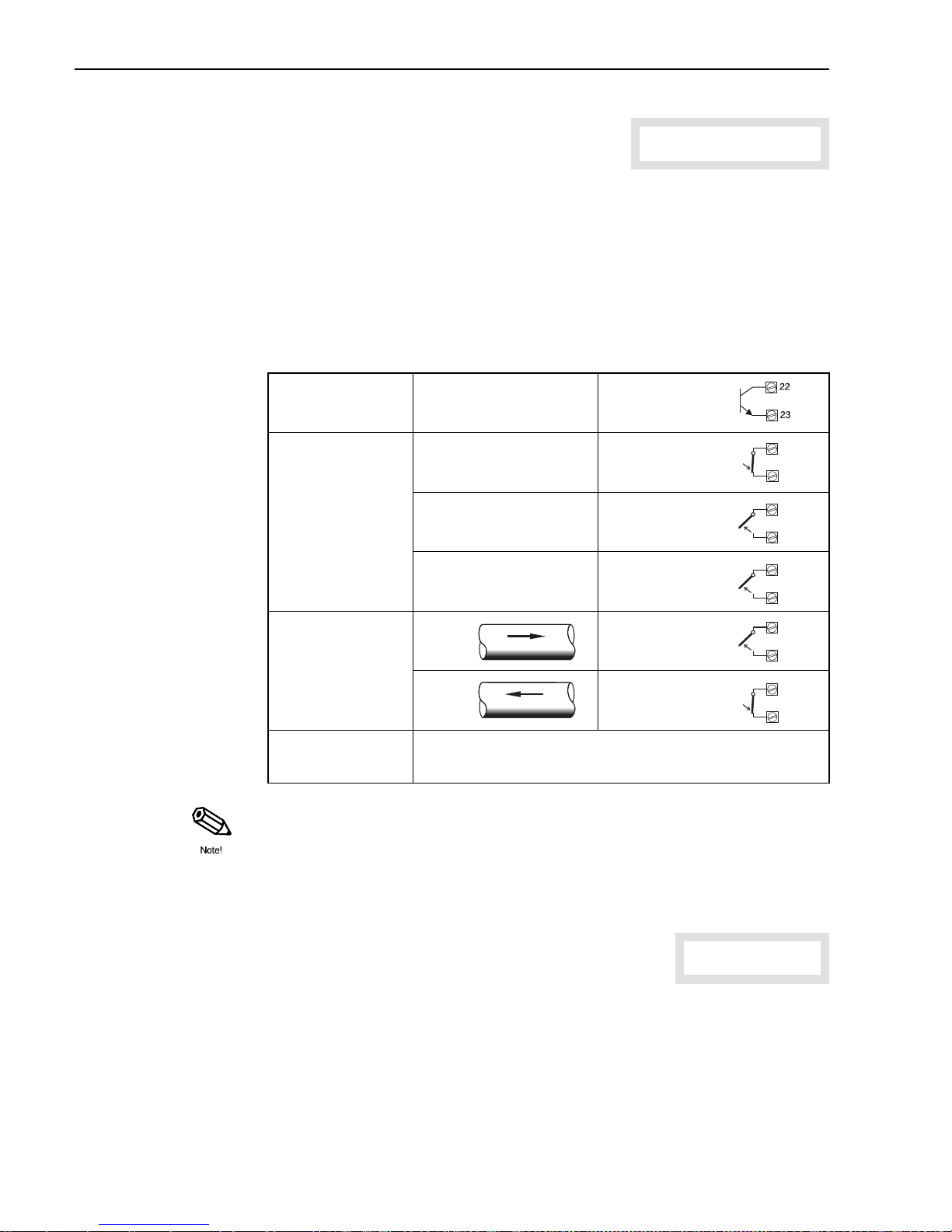
➤ Status output
Works setting: Error messages
Switch No. 2: OFF
This switched output can optionally be configured for:
• Signalling the direction of flow
• Error messages:
– Fault (System error: coil current error, amplifier error DAT error, EEPROM error,
ROM error, RAM error)
– Alarm (Process error: measuring range exceeded, v ≥12.5 m/s)
Supply failure
The status output acts as a normally closed contact, i.e. in normal operation fault, the
output is closed (transistor conducting, see Fig. 36).
Note!
The behaviour of the outputs in the event of a fault is described in section 6.1.
➤ System units
Works setting: SI units
Switch No. 3: OFF
SI units: volume in [dm3, m3]
US units: volume in [US gal]
1 US gallon = 3.7854 dm
3
(Litre)
Configuration of status
output
Status Behaviour of open
collector output
Signalling of system and
process errors
System OK closed
Fault signal/alarm open
Supply failure open
Flow direction
recognition
open
closed
“closed”: open collector ⇒conducting
“open”: open collector ⇒not conducting
Fig. 36
forward
reverse
ba008y33
5. Operation and Commissioning Promag 30
34 Endress+Hauser
Page 35
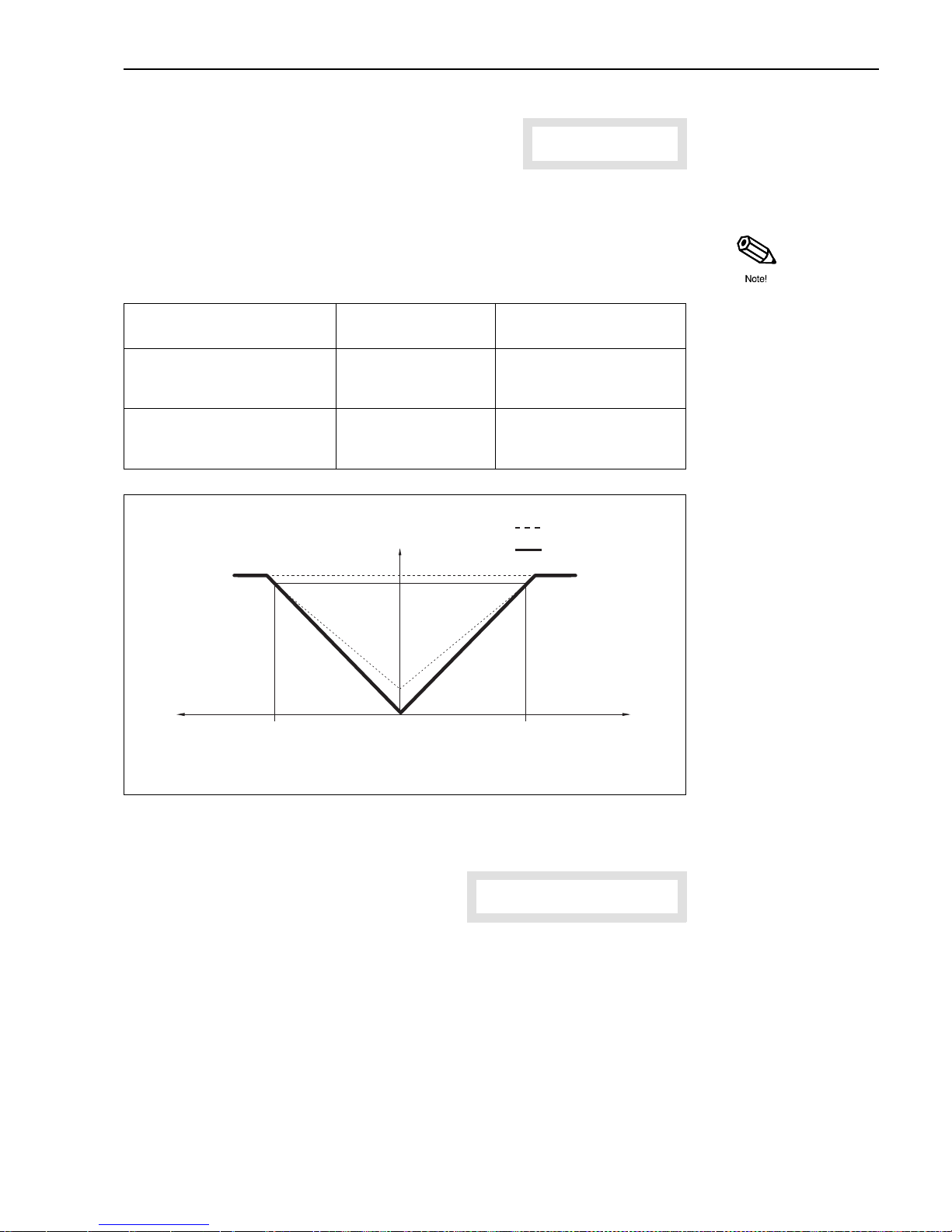
➤ Current range
Works setting: 4...20 mA
Switch No. 4: OFF
The current at zero flow (Q = 0) can be set to 0 or 4 mA. The current for the full-scale
value is always 20 mA. Extension to 20,5 mA is possible.
Note!
The Promag 30 measuring system can be operated in a bidirectional or unidirectional
mode. Selecting this mode is dependent on the status output and functions as follows:
➤ Pulse value
Works setting: at v ~ 2.5 m/s
Switches No. 5, 6, 7: OFF-OFF-ON
The pulse value indicates for what freely selected volume flow an output pulse is
emitted. With an external counter these pulses can be totalled enabling the total
volume flow to be determined.
The pulse-pause ratio is approx. 1:1. The pulse width is limited to a maximum of 2 s
(≤0.25 Hz). At f = 400 Hz the maximum pulse width is 1 ms.
For the Promag 30 measuring system eight preset pulse-value steps can be selected
in terms of the nominal diameter. Setting is made by means of three miniature
switches (see page 37).
Configuration of status output Operating mode Function
Flow direction Bidirectional
•
Continuous current and
pulse output
System and process errors Unidirectional
•
Current and pulse output for
positive flow direction only
I [mA]
Forward
flow
Reverse
flow
Scaled fullscale value
(end value)
Scaled fullscale value
(end value)
[Volume/time]
Q
-Q
4...20 mA
0...20 mA
20,5
20
ba008y34
Fig. 37
Promag 30 5. Operation and Commissioning
Endress+Hauser 35
Page 36
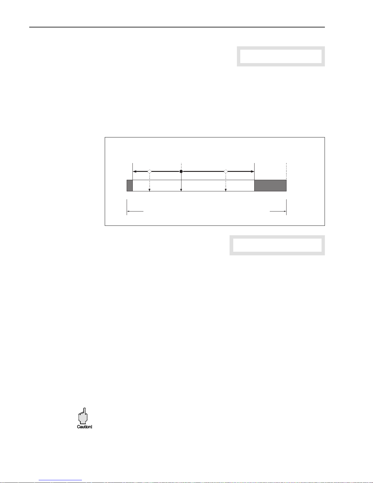
➤ Setting the full-scale value
Works setting: at v ~ 2.5 m/s
Switches No. 8, 9, 10: OFF-OFF-ON
The current output supplies signals between 0/4 and 20 mA, corresponding to the
momentary value of the flow. By setting the full-scale, a flow is assigned to the current
of 20 mA. This setting always applies to both directions of flow (bidirectional). The
direction of flow is emitted at the status output with appropriate configuration.
In practice the maximum rate of flow that occurs is not always reliably known.
Therefore it is possible to extend up to 125% (500 Hz, see Fig. 38).
For the Promag 30 measuring system eight preset pulse-value steps can be selected
in terms of the nominal diameter. Setting is made by means of three miniature
switches (see page 37).
➤ Auxiliary input
The auxiliary input cannot be affected
by the miniature switches
•
Measured value suppression:
With the auxiliary input it is possible to keep a check on the behaviour of the current
and pulse outputs by means of an external voltage (3...30 V DC). Provided this
voltage is applied, the current is set to 0 or 4 mA and the pulse output to the
fallback value (transistor not conducting).
Typical application: Interrupting measurement to clean the piping system.
•
Totaliser reset:
The auxiliary input can also be configured as an external reset for the totaliser using
a jumper (only with local display, see page 42, 43).
➤ Electrode Cleaning Circuit ECC (Option)
Conductive material build-up on the electrodes (e.g. magnetite) can lead to errors in
measurement. The electrode cleaning circuit (ECC) has, therefore, been developed to
prevent such a build-up. The cleaning cycles are carried out every 30 minutes for
2...5 secs each depending on the scanning frequency. If the Promag 30 measuring
system is equipped with the electrode cleaning circuit option (ECC), then this can be
switched on and off using the miniature switches on the amplifier board (see Fig. 44,
on page 48). When delivered from the factory, the electrode cleaning circuit is always
switched on. The ECC is not available with the FL version.
Caution!
If the ECC is switched off for a long period of time in an application with conductive
build-up, then material build-up in the measuring pipe can lead to measuring errors.
If there is a large concentration of build-up at one point, then, under certain
circumstances, switching on the ECC may not remove it. In such cases the measuring
pipe is to be cleaned and the build-up removed.
500 Hz
ba008y35
Measuring range for Promag 30 electronics
Flow rate Q ~ Medium velocity v
Maximum
full-scale value
20 mA current
Minimum
full-scale value
0 0.5
10
12.5 [m/s]
Fig. 38
5. Operation and Commissioning Promag 30
36 Endress+Hauser
Page 37
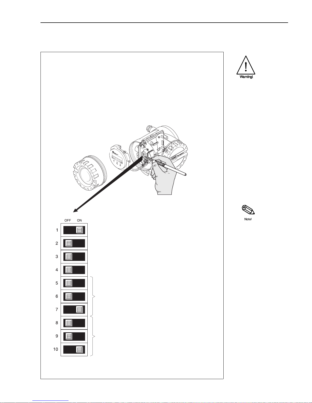
5.2 Setting unit parameters with miniature switches
Warning!
• Danger of electric shock! Switch off the supply voltage before you unscrew the cover of the
electronic compartment of the transmitter housing.
• Do not fail to observe the supplementary Ex documentation for Ex-certified instruments
(in particular regarding rates of cooling).
1. Loosen the screws of the safety grip (3 mm Allen key).
2. Unscrew the cover of the electronics area.
3. Remove the local display (if present).
4. Set the miniature switches.
5. Put back the local display
6. Screw the cover to the electronics area securely on the transmitter housing
ON Creep suppression ⇒ On
OFF Creep suppression ⇒ Off
ON Status output ⇒ Flow direction
OFF Status output ⇒ System/process fault indication
ON US technical units [gal]
OFF SI technical units [m
3
, dm3]
ON 0 ... 20 mA current range
OFF 4 ... 20 mA current range
Setting pulse weighting:
For switch settings ⇒ see Tables A and B on Pages 38 and 39
Scaling the end value (flow at 20 mA):
Switch setting ⇒ see Tables C and D on Pages 40 and 41
Miniature switch 1-10
(Works settings)
ba008y39
Fig. 39
Note!
On request, Promag 30
measuring instruments are
also available with customized
parameterization. In such
cases, switching positions
may differ from the works
settings shown here.
Promag 30 5. Operation and Commissioning
Endress+Hauser 37
Page 38
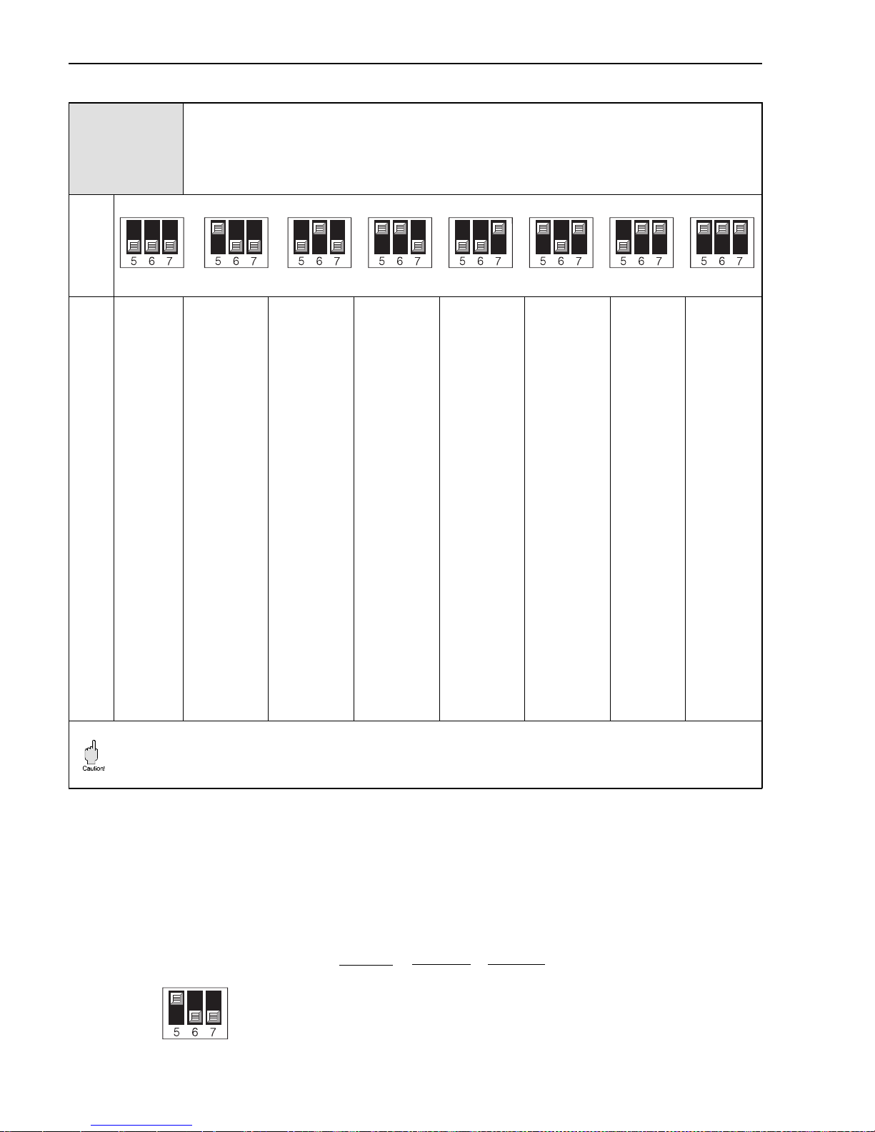
For each nominal diameter is a choice of eight pulse values (in decadic steps).
A definite frequency value (f
max
= 400 Hz at v = 10 m/s, pulse width = 1 ms) is only
available for a single switch position.
Example:
A maximum permissible pulse frequency f
max
= 20 Hz (input frequency of electronic
counter) should not be exceeded. The nominal diameter is assumed to be 25 mm; the
rate of flow Q = 10.8 m
3
/h
Pulse value =
Q = 10.8 m
3
/h = 3 dm3/s
= 0.15 dm
3
f
max
20 s-1 20 s
-1
At DN 25 select the switch position for the next higher pulse value ⇒ 1 dm3 per pulse.
Conversely, when the flow rate Q is known and a pulse value has been selected, the
exact pulse frequency can be calculated.
Table
A
Pulse value ⇒ SI units [dm3/pulse, m3/pulse]
Switch No. 5, 6 and 7
DN
[mm]
2
4
8
15
25
32
40
50
65
80
100
125
150
200
250
300
350
400
450
500
600
700
800
900
1000
1200
1400
1600
1800
2000
0.0001 dm
3
0.001 dm
3
0.01 dm
3
0.01 dm
3
0.1 dm
3
0.1 dm
3
0.1 dm
3
0.1 dm
3
0.1 dm
3
1dm
3
1dm
3
1dm
3
1dm
3
1dm
3
10 dm
3
10 dm
3
10 dm
3
10 dm
3
10 dm
3
10 dm
3
10 dm
3
100 dm
3
100 dm
3
100 dm
3
100 dm
3
100 dm
3
100 dm
3
100 dm
3
100 dm
3
100 dm
3
0.001 dm
3
0.01 dm
3
0.1 dm
3
0.1 dm
3
1dm
3
1dm
3
1dm
3
1dm
3
1dm
3
10 dm
3
10 dm
3
10 dm
3
10 dm
3
10 dm
3
100 dm
3
100 dm
3
100 dm
3
100 dm
3
100 dm
3
100 dm
3
100 m
3
1m
3
1m
3
1m
3
1m
3
1m
3
1m
3
1m
3
1m
3
1m
3
0.01 dm
3
0.1 dm
3
1dm
3
1dm
3
10 dm
3
10 dm
3
10 dm
3
10 dm
3
10 dm
3
100 dm
3
100 dm
3
100 dm
3
100 dm
3
100 dm
3
1m
3
1m
3
1m
3
1m
3
1m
3
1m
3
1m
3
10 m
3
10 m
3
10 m
3
10 m
3
10 m
3
10 m
3
10 m
3
10 m
3
10 m
3
0.1 dm
3
1dm
3
10 dm
3
10 dm
3
100 dm
3
100 dm
3
100 dm
3
100 dm
3
100 dm
3
1m
3
1m
3
1m
3
1m
3
1m
3
10 m
3
10 m
3
10 m
3
10 m
3
10 m
3
10 m
3
10 m
3
100 m
3
100 m
3
100 m
3
100 m
3
100 m
3
100 m
3
100 m
3
100 m
3
100 m
3
1dm3
10 dm
3
100 dm
3
100 dm
3
1m
3
1m
3
1m
3
1m
3
1m
3
10 m
3
10 m
3
10 m
3
10 m
3
10 m
3
100 m
3
100 m
3
100 m
3
100 m
3
100 m
3
100 m
3
100 m
3
1000 m
3
1000 m
3
1000 m
3
1000 m
3
1000 m
3
1000 m
3
1000 m
3
1000 m
3
1000 m
3
10 dm3
100 dm
3
1m
3
1m
3
10 m
3
10 m
3
10 m
3
10 m
3
10 m
3
100 m
3
100 m
3
100 m
3
100 m
3
100 m
3
1000 m
3
1000 m
3
1000 m
3
1000 m
3
1000 m
3
1000 m
3
1000 m
3
10000 m
3
10000 m
3
10000 m
3
10000 m
3
10000 m
3
10000 m
3
10000 m
3
10000 m
3
10000 m
3
100 dm3
1m
3
10 m
3
10 m
3
100 m
3
100 m
3
100 m
3
100 m
3
100 m
3
1000 m
3
1000 m
3
1000 m
3
1000 m
3
1000 m
3
10000 m
3
10000 m
3
10000 m
3
10000 m
3
10000 m
3
10000 m
3
10000 m
3
100000 m
3
100000 m
3
100000 m
3
100000 m
3
100000 m
3
100000 m
3
100000 m
3
100000 m
3
100000 m
3
0.000079 dm3
0.000314 dm
3
0.001257 dm
3
0.004418 dm
3
0.012272 dm
3
0.020106 dm
3
0.031416 dm
3
0.049087 dm
3
0.082958 dm
3
0.125664 dm
3
0.196350 dm
3
0.306796 dm
3
0.441786 dm
3
0.785398 dm
3
1.22718 dm
3
1.76715 dm
3
2.40528 dm
3
3.14159 dm
3
3.97608 dm
3
4.90874 dm
3
7.06858 dm
3
9.62113 dm
3
12.5664 dm
3
15.9043 dm
3
19.6350 dm
3
28.2743 dm
3
38.4845 dm
3
50.2655 dm
3
63.6173 dm
3
78.5398 dm
3
Caution!
Work with this table only when you have turned switch No. 3 to “OFF” (SI units).
For switching position "ON-ON-ON", set values may differ fron those shown in the table. In such cases, the valid value may be read
from the service plate in the electronics compartment cover. Also, the pulse duty cycle of 1:1 can deviate.
(f
max
= 400 Hz
at v = 10 m/s)
5. Operation and Commissioning Promag 30
38 Endress+Hauser
Page 39
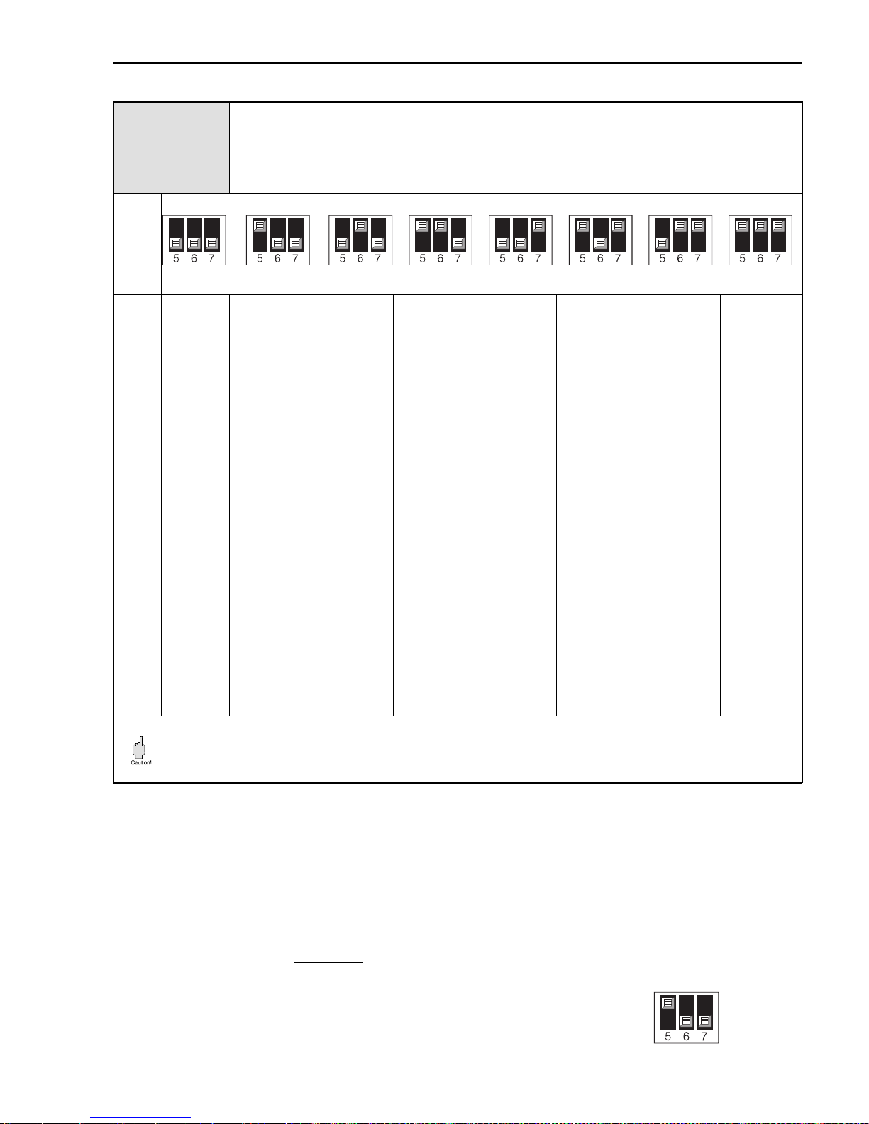
For each nominal diameter there is a choice of eight pulse values (in decade steps).
A definite frequency value (f
max
= 400 Hz at v = 33 ft/s, pulse width = 1 ms) is only
available for a single switch position.
Example:
A maximum permissible pulse frequency f
max
= 20 Hz (input frequency of an
electronic counter) should not be exceeded. The nominal diameter is assumed to be
80 mm; the rate of flow Q = 600 USgal/min.
Pulse value =
Q = 600 gal/min = 10 gal/s
= 0.5 gal
f
max
20 s-1 20 s
-1
At DN 80 select the switch position for the next higher pulse value ⇒ 1 gal per pulse.
Conversely when the flow rate Q is known and a pulse value has been selected, the
exact pulse frequency can be calculated.
(f
max
= 400 Hz
at v = 33 ft/sec)
Table
B
Pulse value ⇒ US units [gal/pulse]
Switch No. 5, 6 and 7
DN
[mm]
2
4
8
15
25
32
40
50
65
80
100
125
150
200
250
300
350
400
450
500
600
700
800
900
1000
1200
1400
1600
1800
2000
0.0001 gal
0.0001 gal
0.001 gal
0.01 gal
0.01 gal
0.01 gal
0.01 gal
0.1 gal
0.1 gal
0.1 gal
0.1 gal
0.1 gal
1gal
1gal
1gal
1gal
1gal
1gal
10 gal
10 gal
10 gal
10 gal
10 gal
10 gal
10 gal
10 gal
100 gal
100 gal
100 gal
100 gal
0.001 gal
0.001 gal
0.01 gal
0.1 gal
0.1 gal
0.1 gal
0.1 gal
1gal
1gal
1gal
1gal
1gal
10 gal
10 gal
10 gal
10 gal
10 gal
10 gal
100 gal
100 gal
100 gal
100 gal
100 gal
100 gal
100 gal
100 gal
1000 gal
1000 gal
1000 gal
1000 gal
0.01 gal
0.01 gal
0.1 gal
1gal
1gal
1gal
1gal
10 gal
10 gal
10 gal
10 gal
10 gal
100 gal
100 gal
100 gal
100 gal
100 gal
100 gal
1000 gal
1000 gal
1000 gal
1000 gal
1000 gal
1000 gal
1000 gal
1000 gal
10000 gal
10000 gal
10000 gal
10000 gal
0.1 gal
0.1 gal
1gal
10 gal
10 gal
10 gal
10 gal
100 gal
100 gal
100 gal
100 gal
100 gal
1000 gal
1000 gal
1000 gal
1000 gal
1000 gal
1000 gal
10000 gal
10000 gal
10000 gal
10000 gal
10000 gal
10000 gal
10000 gal
10000 gal
100000 gal
100000 gal
100000 gal
100000 gal
1gal
1gal
10 gal
100 gal
100 gal
100 gal
100 gal
1000 gal
1000 gal
1000 gal
1000 gal
1000 gal
10000 gal
10000 gal
10000 gal
10000 gal
10000 gal
10000 gal
100000 gal
100000 gal
100000 gal
100000 gal
100000 gal
100000 gal
100000 gal
100000 gal
1000000 gal
1000000 gal
1000000 gal
1000000 gal
10 gal
10 gal
100 gal
1000 gal
1000 gal
1000 gal
1000 gal
10000 gal
10000 gal
10000 gal
10000 gal
10000 gal
100000 gal
100000 gal
100000 gal
100000 gal
100000 gal
100000 gal
1000000 gal
1000000 gal
1000000 gal
1000000 gal
1000000 gal
1000000 gal
1000000 gal
1000000 gal
10000000 gal
10000000 gal
10000000 gal
10000000 gal
100 gal
100 gal
1000 gal
10000 gal
10000 gal
10000 gal
10000 gal
100000 gal
100000 gal
100000 gal
100000 gal
100000 gal
1000000 gal
1000000 gal
1000000 gal
1000000 gal
1000000 gal
1000000 gal
10000000 gal
10000000 gal
10000000 gal
10000000 gal
10000000 gal
10000000 gal
10000000 gal
10000000 gal
100000000 gal
100000000 gal
100000000 gal
100000000 gal
0.00002087 gal
0.00008348 gal
0.0003339 gal
0.001174 gal
0.003261 gal
0.005343 gal
0.008348 gal
0.01304 gal
0.02204 gal
0.03339 gal
0.05217 gal
0.08152 gal
0.1174 gal
0.2087 gal
0.3261 gal
0.4696 gal
0.6391 gal
0.8348 gal
1.057 gal
1.304 gal
1.878 gal
2.556 gal
3.339 gal
4.226 gal
5.217 gal
7.513 gal
10.23 gal
13.36 gal
16.90 gal
20.87 gal
Caution!
Work with this table only when you have turned switch No. 3 to “ON” (US units).
For switching position "ON-ON-ON", set values may differ fron those shown in the table. In such cases, the valid value may be read
from the service plate in the electronics compartment cover. Also, the pulse duty cycle of 1:1 can deviate.
Promag 30 5. Operation and Commissioning
Endress+Hauser 39
Page 40
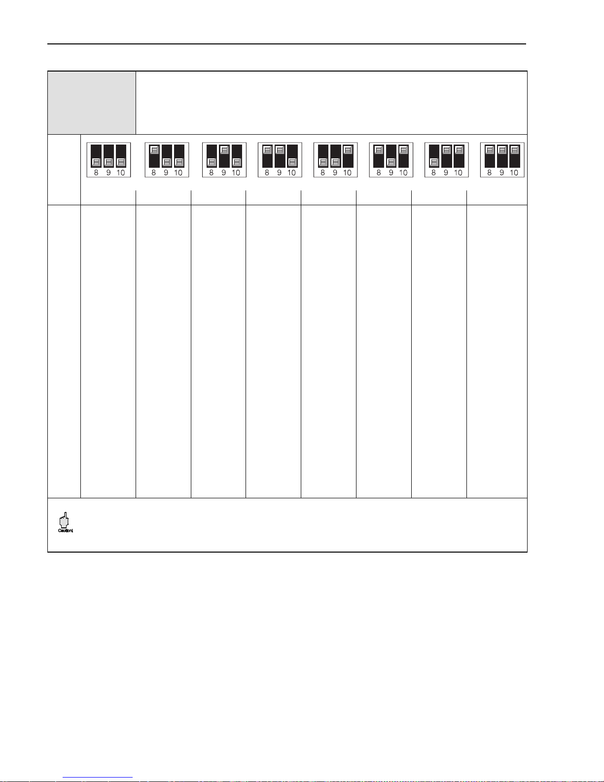
For each nominal diameter, at a current of 20 mA, eight flow values (full-scale values)
can be selected from the above table.
Table
C
Full-scale value setting ⇒ SI units [m3/h]
Switch No. 8, 9 and 10
DN
[mm]
0.5 m/s 1 m/s 1.5 m/s 2 m/s 2.5 m/s 5 m/s 8 m/s 10 m/s
2
4
8
15
25
32
40
50
65
80
100
125
150
200
250
300
350
400
450
500
600
700
800
900
1000
1200
1400
1600
1800
2000
0.005m3/h
0.02 m
3
/h
0.1 m
3
/h
0.3 m
3
/h
1m
3
/h
1.5 m
3
/h
2m
3
/h
4m
3
/h
6m
3
/h
10 m
3
/h
15 m
3
/h
20 m
3
/h
30 m
3
/h
50 m
3
/h
100 m
3
/h
150 m
3
/h
200 m
3
/h
200 m
3
/h
300 m
3
/h
400 m
3
/h
600 m
3
/h
800 m
3
/h
1000 m
3
/h
1000 m
3
/h
1500 m
3
/h
2000 m
3
/h
3000 m
3
/h
4000 m
3
/h
5000 m
3
/h
5000 m
3
/h
0.01 m
3
/h
0.04 m
3
/h
0.2 m
3
/h
0.6 m
3
/h
2m
3
/h
3m
3
/h
4m
3
/h
8m
3
/h
12 m
3
/h
20 m
3
/h
30 m
3
/h
40 m
3
/h
60 m
3
/h
100 m
3
/h
200 m
3
/h
300 m
3
/h
400 m
3
/h
400 m
3
/h
600 m
3
/h
800 m
3
/h
1200 m
3
/h
1600 m
3
/h
2000 m
3
/h
2000 m
3
/h
3000 m
3
/h
4000 m
3
/h
6000 m
3
/h
8000 m
3
/h
10000 m
3
/h
10000 m
3
/h
0.015m
3
/h
0.06 m
3
/h
0.3 m
3
/h
0.9 m
3
/h
3m
3
/h
4.5 m
3
/h
6m
3
/h
12 m
3
/h
18 m
3
/h
30 m
3
/h
45 m
3
/h
60 m
3
/h
90 m
3
/h
150 m
3
/h
300 m
3
/h
450 m
3
/h
600 m
3
/h
600 m
3
/h
900 m
3
/h
1200 m
3
/h
1800 m
3
/h
2400 m
3
/h
3000 m
3
/h
3000 m
3
/h
4500 m
3
/h
6000 m
3
/h
9000 m
3
/h
12000 m
3
/h
15000 m
3
/h
15000 m
3
/h
0.02 m
3
/h
0.08 m
3
/h
0.4 m
3
/h
1.2 m
3
/h
4m
3
/h
6m
3
/h
8m
3
/h
16 m
3
/h
24 m
3
/h
40 m
3
/h
60 m
3
/h
80 m
3
/h
120 m
3
/h
200 m
3
/h
400 m
3
/h
600 m
3
/h
800 m
3
/h
800 m
3
/h
1200 m
3
/h
1600 m
3
/h
2400 m
3
/h
3200 m
3
/h
4000 m
3
/h
4000 m
3
/h
6000 m
3
/h
8000 m
3
/h
12000 m
3
/h
16000 m
3
/h
20000 m
3
/h
20000 m
3
/h
0.025m
3
/h
0.1 m
3
/h
0.5 m
3
/h
1.5 m
3
/h
5m
3
/h
7.5 m
3
/h
10 m
3
/h
20 m
3
/h
30 m
3
/h
50 m
3
/h
75 m
3
/h
100 m
3
/h
150 m
3
/h
250 m
3
/h
500 m
3
/h
750 m
3
/h
1000 m
3
/h
1000 m
3
/h
1500 m
3
/h
2000 m
3
/h
3000 m
3
/h
4000 m
3
/h
5000 m
3
/h
5000 m
3
/h
7500 m
3
/h
10000 m
3
/h
15000 m
3
/h
20000 m
3
/h
25000 m
3
/h
25000 m
3
/h
0.05 m
3
/h
0.2 m
3
/h
1m
3
/h
3m
3
/h
10 m
3
/h
15 m
3
/h
20 m
3
/h
40 m
3
/h
60 m
3
/h
100 m
3
/h
150 m
3
/h
200 m
3
/h
300 m
3
/h
500 m
3
/h
1000 m
3
/h
1500 m
3
/h
2000 m
3
/h
2000 m
3
/h
3000 m
3
/h
4000 m
3
/h
6000 m
3
/h
8000 m
3
/h
10000 m
3
/h
10000 m
3
/h
15000 m
3
/h
20000 m
3
/h
30000 m
3
/h
40000 m
3
/h
50000 m
3
/h
50000 m
3
/h
0.08 m
3
/h
0.32 m
3
/h
1.6 m
3
/h
4.8 m
3
/h
16 m
3
/h
24 m
3
/h
32 m
3
/h
64 m
3
/h
96 m
3
/h
160 m
3
/h
240 m
3
/h
320 m
3
/h
480 m
3
/h
800 m
3
/h
1600 m
3
/h
2400 m
3
/h
3200 m
3
/h
3200 m
3
/h
4800 m
3
/h
6400 m
3
/h
9600 m
3
/h
12800 m
3
/h
16000 m
3
/h
16000 m
3
/h
24000 m
3
/h
32000 m
3
/h
48000 m
3
/h
64000 m
3
/h
80000 m
3
/h
80000 m
3
/h
0.1 m
3
/h
0.4 m
3
/h
2m
3
/h
6m
3
/h
20 m
3
/h
30 m
3
/h
40 m
3
/h
80 m
3
/h
120 m
3
/h
200 m
3
/h
300 m
3
/h
400 m
3
/h
600 m
3
/h
1000 m
3
/h
2000 m
3
/h
3000 m
3
/h
4000 m
3
/h
4000 m
3
/h
6000 m
3
/h
8000 m
3
/h
12000 m
3
/h
16000 m
3
/h
20000 m
3
/h
20000 m
3
/h
30000 m
3
/h
40000 m
3
/h
60000 m
3
/h
80000 m
3
/h
100000 m
3
/h
100000 m
3
/h
Caution!
Work with this table only when you have turned switch No. 3 to “OFF” (SI units).
For switching position "ON-ON-ON", set values may differ from those shown in the table. In such cases, the valid value may be read
from the service plate in the electronics compartment cover.
5. Operation and Commissioning Promag 30
40 Endress+Hauser
Page 41
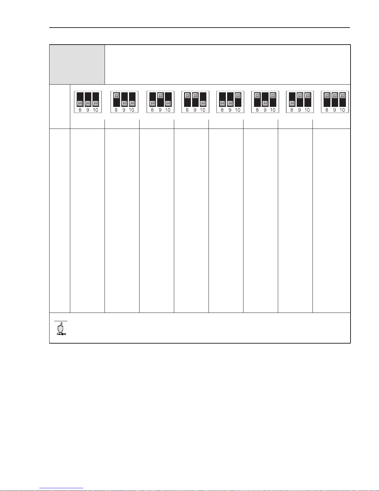
For each nominal diameter, at a current of 20 mA, eight flow values (full-scale values)
can be selected from the above table.
(v = 33 ft/sec)
Table
D
Full-scale value setting ⇒ US units [gal/min]
Switch No. 8, 9 and 10
DN
[mm]
0.5 m/s1 m/s1.5 m/s2 m/s2.5 m/s5 m/s 8 m/s 10 m/s
2
4
8
15
25
32
40
50
65
80
100
125
150
200
250
300
350
400
450
500
600
700
800
900
1000
1200
1400
1600
1800
2000
0.02 gal/min
0.1 gal/min
0.5 gal/min
1.5 gal/min
5gal/ min
7.5 gal/min
10 gal/min
20 gal/min
30 gal/min
50 gal/min
75 gal/min
100 gal/min
150 gal/min
250 gal/min
500 gal/min
750 gal/min
1000 gal/min
1000 gal/min
1500 gal/min
2000 gal/min
3000 gal/min
4000 gal/min
5000 gal/min
5000 gal/min
7500 gal/min
10000 gal/min
15000 gal/min
20000 gal/min
25000 gal/min
25000 gal/min
0.05 gal/min
0.2 gal/min
1gal/ min
3gal/ min
10 gal/min
15 gal/min
20 gal/min
40 gal/min
60 gal/min
100 gal/min
150 gal/min
200 gal/min
300 gal/min
500 gal/min
1000 gal/min
1500 gal/min
2000 gal/min
2000 gal/min
3000 gal/min
4000 gal/min
6000 gal/min
8000 gal/min
10000 gal/min
10000 gal/min
15000 gal/min
20000 gal/min
30000 gal/min
40000 gal/min
50000 gal/min
50000 gal/min
0.075gal/min
0.3 gal/min
1.5 gal/min
4.5 gal/min
15 gal/min
22.5 gal/min
30 gal/min
60 gal/min
90 gal/min
150 gal/min
225 gal/min
300 gal/min
450 gal/min
750 gal/min
1500 gal/min
2250 gal/min
3000 gal/min
3000 gal/min
4500 gal/min
6000 gal/min
9000 gal/min
12000 gal/min
15000 gal/min
15000 gal/min
22500 gal/min
30000 gal/min
45000 gal/min
60000 gal/min
75000 gal/min
75000 gal/min
0.1 gal/min
0.4 gal/min
2gal/ min
6gal/ min
20 gal/min
30 gal/min
40 gal/min
80 gal/min
120 gal/min
200 gal/min
300 gal/min
400 gal/min
600 gal/min
1000 gal/min
2000 gal/min
3000 gal/min
4000 gal/min
4000 gal/min
6000 gal/min
8000 gal/min
12000 gal/min
16000 gal/min
20000 gal/min
20000 gal/min
30000 gal/min
40000 gal/min
60000 gal/min
80000 gal/min
100000 gal/min
100000 gal/min
0.125gal/min
0.5 gal/min
2.5 gal/min
7.5 gal/min
25 gal/min
37.5 gal/min
50 gal/min
100 gal/min
150 gal/min
250 gal/min
375 gal/min
500 gal/min
750 gal/min
1250 gal/min
2500 gal/min
3750 gal/min
5000 gal/min
5000 gal/min
7500 gal/min
10000 gal/min
15000 gal/min
20000 gal/min
25000 gal/min
25000 gal/min
37500 gal/min
50000 gal/min
75000 gal/min
100000 gal/min
125000 gal/min
125000 gal/min
0.25 gal/min
1gal/ min
5gal/ min
15 gal/min
50 gal/min
75 gal/min
100 gal/min
200 gal/min
300 gal/min
500 gal/min
750 gal/min
1000 gal/min
1500 gal/min
2500 gal/min
5000 gal/min
7500 gal/min
10000 gal/min
10000 gal/min
15000 gal/min
20000 gal/min
30000 gal/min
40000 gal/min
50000 gal/min
50000 gal/min
75000 gal/min
100000 gal/min
150000 gal/min
200000 gal/min
250000 gal/min
250000 gal/min
0.4 gal/min
1.6 gal/min
8gal/ min
24 gal/min
80 gal/min
120 gal/min
160 gal/min
320 gal/min
480 gal/min
800 gal/min
1200 gal/min
1600 gal/min
2400 gal/min
4000 gal/min
8000 gal/min
12000 gal/min
16000 gal/min
16000 gal/min
24000 gal/min
32000 gal/min
48000 gal/min
64000 gal/min
80000 gal/min
80000 gal/min
120000 gal/min
160000 gal/min
240000 gal/min
320000 gal/min
400000 gal/min
400000 gal/min
0.5 gal/min
2gal/ min
10 gal/min
30 gal/min
100 gal/min
150 gal/min
200 gal/min
400 gal/min
600 gal/min
1000 gal/min
1500 gal/min
2000 gal/min
3000 gal/min
5000 gal/min
10000 gal/min
15000 gal/min
20000 gal/min
20000 gal/min
30000 gal/min
40000 gal/min
60000 gal/min
80000 gal/min
100000 gal/min
100000 gal/min
150000 gal/min
200000 gal/min
300000 gal/min
400000 gal/min
500000 gal/min
500000 gal/min
Caution!
Work with this table only when you have turned switch No. 3 to “ON” (US units).
For switching position "ON-ON-ON", set values may differ from those shown in the table. In such cases, the valid value may be read
from the service plate in the electronics compartment cover.
Promag 30 5. Operation and Commissioning
Endress+Hauser 41
Page 42
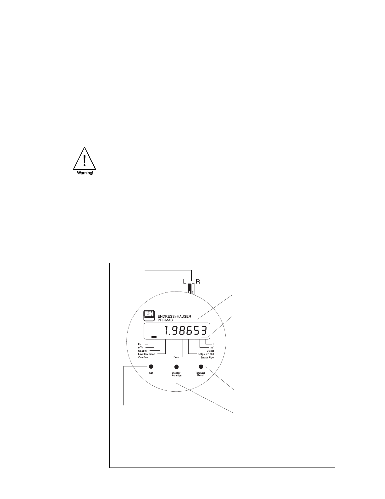
5.3 Local display
With the Promag 30 local display important variables can be read off and controlled
directly at the measuring point:
• Flow rate and/or totaliser value.
• Technical units (SI or US).
• Process conditions (creep. partially empty pipe).
• Error messages.
It is possible to access, activate, and set various functions in sequence with the help
of the three operating keys on the local display.
1. Loosen Allen screw (3 mm) of the safety grip. Unscrew the cover of the
electronics compartment.
2. The keys may now be operated by pressing with a thin (non-conductive) pin.
A switching cycle takes about 0.5...0.8 seconds.
3. Firmly screw back the cover of the electronics compartment to the transmitter
housing once the settings have been entered. Firmly tighten the Allen screw of the
safety grip.
Jumper
Description ⇒ see next page:
“Additional Information”
Set
This key is used for carrying out the following
operations within the appropriate function:
•
Selecting the technical units
•
Switching on/off the EPD (Empty Pipe Detection)
•
Starting the empty/full pipe adjustment
(for Empty Pipe Detection)
ba008y37
LCD, 8-character
All measured values, operating and status
indications are shown here.
11 Display segments
The appropriate segments serve to provide
clear information on technical units and
current instrument function:
•
Current technical unit
•
Creep too low (Low flow cut-off)
•
Velocity of fluid > 12.5 m/s
•
System fault (error)
•
Partially filled pipe (Empty Pipe Detection)
Totalizer reset
This key is used for resetting totalizer to “0”
(in the “
tot
” function only).
Display function
This key is used for selecting the function
required (= display mode). By continuously
pressing the key, the individual functions are
called up automatically on at a time.
Fig. 40
Danger of electrical shock!
With the housing cover removed, protection against accidental contact
is no longer present. Components with high voltages are exposed below the local
display. When programming according to section 5.3, avoid any contact with the
electronic components which lie below the local display, and do not use any
electrically conductive object to depress the programming keys.
5. Operation and Commissioning Promag 30
42 Endress+Hauser
Page 43
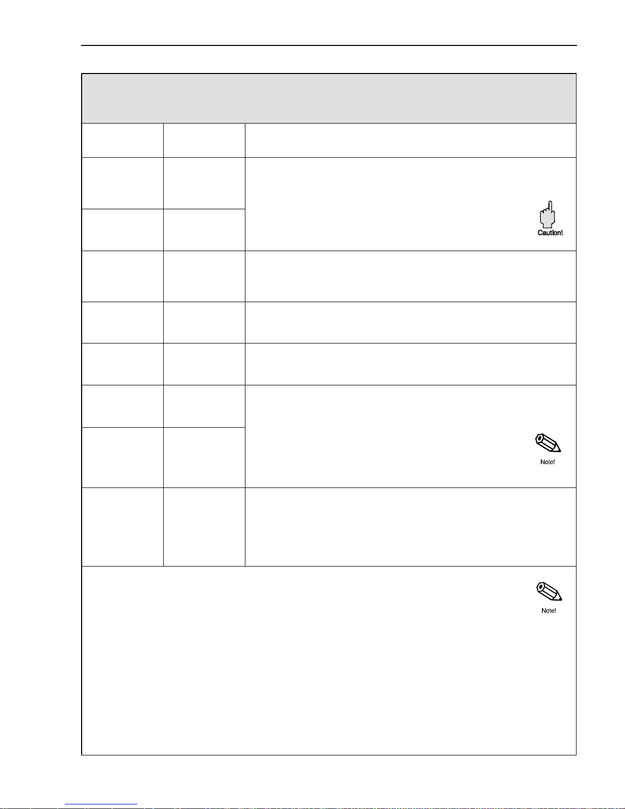
Display functions
Display Function Description
rAtE
Display flow rate Display of the current flow rate or totaliser volume. A negative flow direction is indicated
by a negative digit.
To select the measuring unit ⇒ press “Set” key
tot
Display totaliser Caution!
Setting of SI/US units is done by miniature switches on the measuring
amplifier board (see page 37)
.
dISP-OF
Display
overflow totaliser
Display of the number of overflows at numerical values >
99 999 999
.
A maximum of 21 overflows is displayed. Starting with the 22nd overflow,
the totaliser begins to sum up from “0” upwards.
rAtE-tot
Display
Flow rate/totaliser
Alternating display (about every 10 seconds) of the current flow rate and totaliser value.
EPd-oFF
Empty Pipe
Detection (EPD)
The EPD function detects whether a measuring pipe is only partially filled with liquid
For ON/OFF switching ⇒ press “Set” key
EPd-Ad_E
Empty pipe
adjustment
Empty/full pipe adjustment for EPD
To start adjustment ⇒ press “Set” key
EPd-Ad_F
Full pipe adjustment Note!
• Any adjustment has to be done before switching on EPD
(otherwise the
ADJ_ERROR
message is displayed).
• During adjustment the message
ADJ_BUSY
is displayed
for about 0.5 s. After any adjustment
ADJ_DONE
is displayed
tESt
Test function Accessing this function activates an automatic test sequence of all display elements;
the following displays are shown:
1.
+ 88 888 888
(incl. display segments)
2.
- 00 000 000
(without display segments)
3. All display elements are blank
4. Flow indication
Additional Information!
• Jumper:
Left position ⇒ auxiliary input configured for “measured value suppression”.
If the measuring value suppression is activated an eight-bar symbol is displayed.
Right position ⇒ auxiliary input configured for “totaliser reset” to allow resetting the totaliser
to “0” independently of the current display mode. The function of the “totaliser Reset” key is maintained.
• In case of system or process errors (incl. EPD) outputs react as described in section 6.1 of the Operating
Manual.
• In case of a supply breakdown, all measuring data (e.g. totaliser value) and configurations are saved and
again available once the device is restarted.
• If a sensor equipped with an EPD electrode has to be exchanged during servicing, then the EPD calibration
must always be carried out again.
Promag 30 5. Operation and Commissioning
Endress+Hauser 43
Page 44

5.4 Commissioning
Before switching the measuring equipment on for the first time repeat the following
checks:
• Check the electrical connections and the allocation of the terminals.
• Compare the data on the nameplate with the local mains voltage and frequency.
• Does the direction of the arrow on the nameplate (sensor) agree with the actual
direction of flow in the piping?
If the results of these checks are satisfactory, switch on the supply voltage.
The unit is ready for operation.
5. Operation and Commissioning Promag 30
44 Endress+Hauser
Page 45
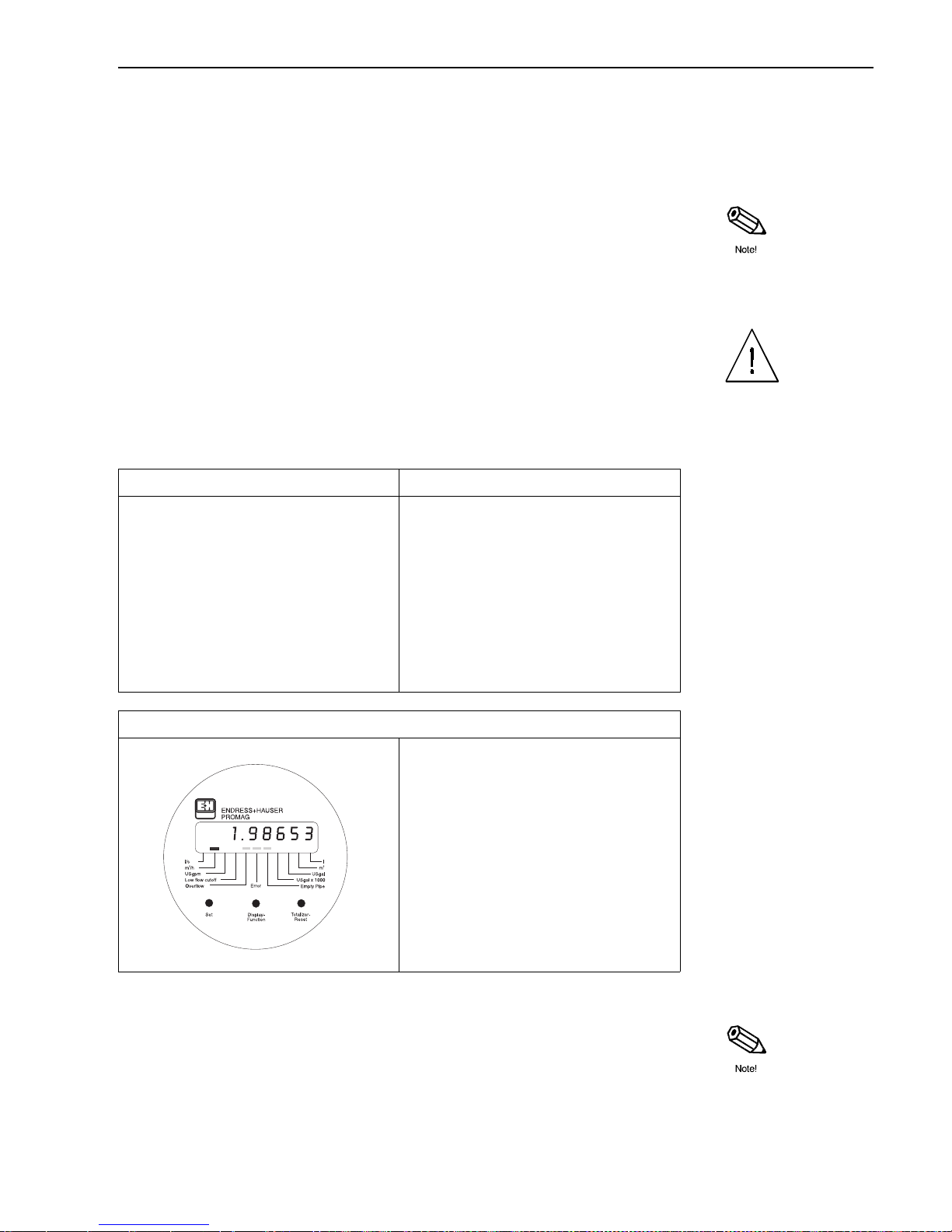
6. Fault Location and Remedies
6.1 Behaviour of the measuring equipment in the event
of a fault or alarm
Notes!
• Errors which occur while operation is in progress are emitted at the status output,
provided its configuration is appropriate (see page 37).
• An LED is also situated on the amplifier board of the Promag 30 (see Fig. 44). This
LED is always lit as long as the measuring system is operating correctly. In case of
error the LED is flushing, thus indicating an error. If the LED ist neither lit nor
flashing there is a power supply breakdown.
Warning!
Error diagnosis for Ex-instruments cannot be done using an LED, as the ignition
protection type is then no longer valid.
The Promag 30 measuring system reacts to faults or an alarm in the following manner:
Type of fault Behaviour of the outputs
➤
Status output open, i.e. open collector not
conducting (see page 34).
System error (fault, failure)
Process error (alarm)
Supply failure
➤
Pulse output: No output of pulses until the
fault has been cleared.
➤
Current output: The current is set to a definite
value until the fault has been cleared.
0...20 mA ⇒ 0 mA
4...20 mA ⇒ 2 mA
Note!
With measured value suppression the following points are important:
• System errors are given as usual over the status output.
• Process errors have a lower priority and are not given at the status output with
active measured value suppression.
Warning!
Error messages on the display
➤
System error ⇒ ERROR segment visible
➤
Process error ⇒ EDP segment visible
(Empty Pipe)
➤
Overflow ⇒ Overflow segment visible
ba008y38
Fig. 41
Promag 30 6. Fault Location and Remedies
Endress+Hauser 45
Page 46
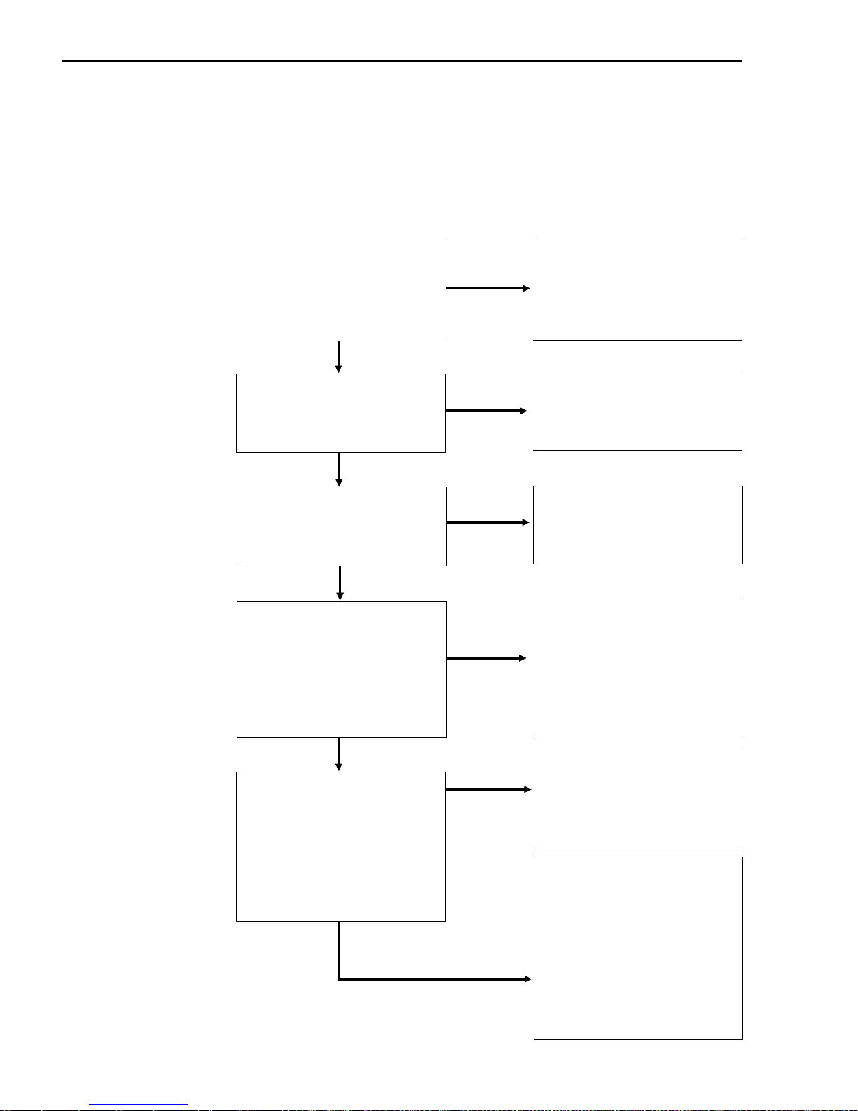
6.2 Instructions for fault location and remedies
During manufacture all units pass through various stages of quality control.
The last inspection is wet calibration, which is carried out on a calibration rig
designed according to the latest state of the art.
As an initial help in the location of faults, here is an overview of possible causes of
faults:
• Is the supply voltage present
at terminals 1, 2?
• Is the LED in the electronics
compartment lit up
(see page 48)
Check that connections
conform to wiring diagrams.
Is the fuse in the terminal
compartment in order?
Replace fuse.
Is the status output set to
"Signalling system and
process errors" ?
Turn switch No. 2 “OFF”
(see page 37).
• Does the status output have
a high impedance? (Open
collector → not conducting)
• ERROR segment = visible?
• Is the LED in the electronics
compartment flashing
(see page 48)?
No system or process error is
present:
• Check the connections to
the outputs.
• Check the parameter
settings, i.e. switch
positions (see page 37).
There is a system error:
Please contact
Endress+Hauser Service
Organisation!
There is a process error:
• “Overflow” segment visible:
Measuring range exceeded
>12,5 m/s. Reduce the flow.
• “ERROR” segment visible:
Measuring pipe not
completely filled. Check the
process conditions of the
installation.
Does the status output have a
low impedance when a
voltage of 3...30 V DC is
applied to the auxiliary input ?
Auxiliary input has previously
been set for measured
value suppression
(see page 42, 43).
No
No
No
No
No
Ye s
Yes
Ye s
Ye s
Yes
6. Fault Location and Remedies Promag 30
46 Endress+Hauser
Page 47
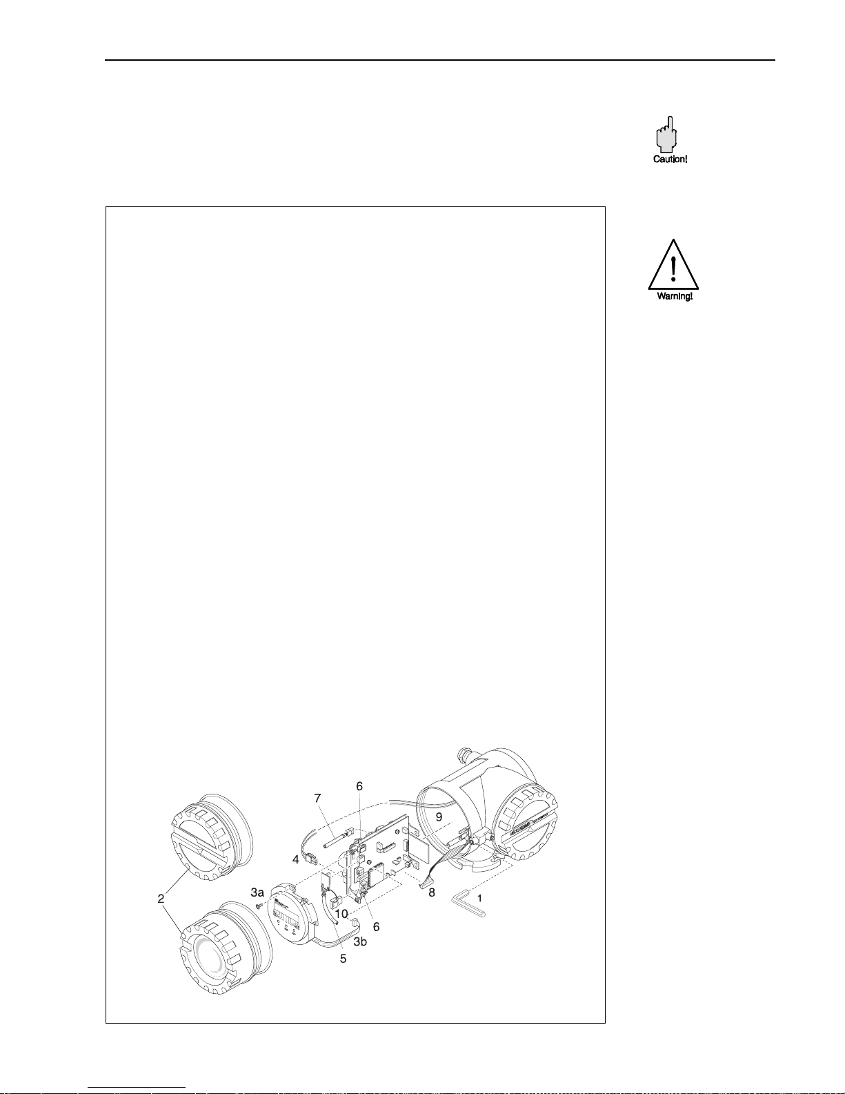
6.3 Replacing the transmitter electronics
Caution!
• When replacing the electronic boards, ensure that their markings are identical.
• The local power supply voltage and frequency must be the same as the technical
specifications of the power supply boards.
ba008y36
Procedure:
Warning!
Danger from electric shock! Switch off the power supply before removing
the cover to the electronics area of the transmitter housing. Switch off the power supply
(isolating the measuring system)
1. Loosen the Allen screws of the safety grip (3-mm Allen key).
2. Unscrew the cover of the electronics area of the transmitter housing.
3. Remove the local display (if present):
a) Loosen the mounting screws of the display module.
b) Unplug the ribbon cable of the display module form the amplifier board.
4. Remove the 2-pole plug of the power supply cable by pressing the catch of the power supply
board at the same time (Fig. 43: V4).
5. Remove the cable board of the screened signal cable from the amplifier board (Fig. 44: V5).
6. Loosen the two Phillips screws of the board support plate. Carefully remove the support plate
approx. 4–5 cm out of the transmitter housing.
7. Remove the coil current cable plug from the power supply board (Fig. 43: V1).
8. Remove the ribbon cable plug (connection cable to the connection terminal area) from the amplifier board (Fig. 44: V8, V9).
9. The entire transmitter electronics, together with the board support plate can now be completely
removed from the housing.
10. If necessary, remove the DAT module from the pin strip (Fig. 44: V 10) on the amplifier board:
– Required when replacing the transmitter electronics → plug the old DAT in the
new amplifier board.
– Required when replacing a defective DAT → plug the new DAT on the old amplifier board.
11. Replace the old transmitter electronics with new transmitter electronics.
12. Reassemble in reverse sequence.
Fig. 42
Promag 30 6. Fault Location and Remedies
Endress+Hauser 47
Page 48
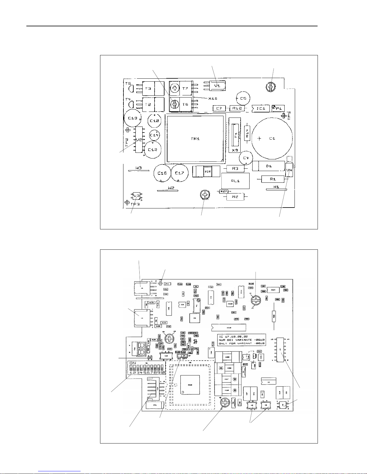
Power supply board (Promag 30)
Measuring amplifier board (Promag 30)
Pin base for coil current cable
Plug for supply cable
Socket
base
Fixing screw
Fixing screw
Fixing screw
Socket
base
ba008y45
Fig. 43
Pin base for connecting the flow simulator “Flowjack”
Pin base for
DAT module
Miniature
switches
(1 - 10)
Socket
base
Sockets for flat ribbon plugs
(connecting with terminal compartment)
fixing screw
Pin base for
electrode
signal cable
Fixing screw
Test point 2
ba008y46
Switch for ECC
Fig. 44
LED for
system
status
6. Fault Location and Remedies Promag 30
48 Endress+Hauser
Page 49

6.4 Replacing the fuse
Warning!
• Danger from electric shock! Switch off the power supply before unscrewing the
cover of the terminal compartment from the transmitter housing (see also page 27f.).
• For flowmeters with Ex approvals the guidelines in the separate Ex documentation
must be strictly followed.
6.5 Repairs
If you return a Promag 30 measuring unit to Endress+Hauser for repair, please
enclose a note giving the following information:
• Description of the application
• Description of the fault
• Chemical and physical properties of the medium measured.
Caution!
Please carry out the following before you return the Promag 30 unit for repair:
• Remove all traces of the medium still adhering.
• This is particularly important if the medium is harmful for health, i.e. caustic,
poisonous, cancerogenous, radioactive, etc. Please ensure that full handling details
i.e. “Fluid Data Sheets” are enclosed.
• We must request you not to return a unit if it is not completely certain that harmful
substances can be removed (e.g. cracks have been penetrated or substances
have diffused through plastics).
Incomplete cleaning of the instrument may result in waste disposal or cause harm to
personnel (burns, etc). Any costs arising from this will be charged to the owner of the
instrument.
Promag 30 6. Fault Location and Remedies
Endress+Hauser 49
Page 50

Promag 30
50 Endress+Hauser
Page 51
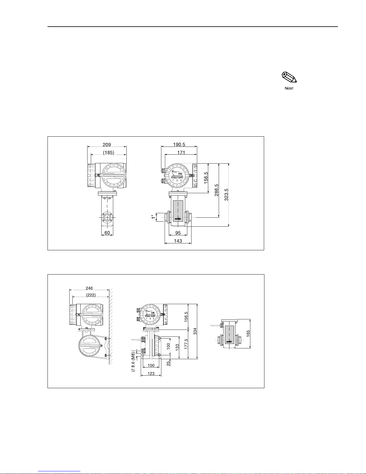
7. Technical Data
7.1 Dimensions and weights
Note!
The dimensions and weights of explosion protected versions may differ from the
specifications given here. These are given in the Ex supplement to this manual.
Promag 30 A
Compact version
Remote-mounted version (FS/FL)
Weights
Compact version: 5 kg (without insert parts)
Promag 30 transmitter: 3 kg (5 kg when wall-mounted)
Promag A sensor: 2 kg
Electrode
axis
Mounting available as
accessory
ba008y41
Fig. 45
ba008y42
Fig. 46
Promag 30 7. Technical Data
Endress+Hauser 51
Page 52
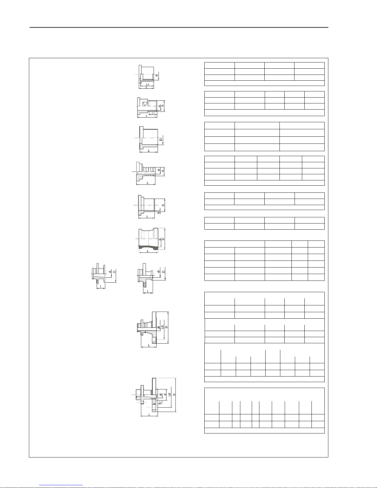
Dimensions of the inserted parts for sensor Promag A
Internal thread
External thread
PVC adhesive coupling
Hose connection
Welded nipple
DN 2...15
Welded nipple
DN 25
Tri-Clamp
Stainless steel
1.4404/316L
Flange
Stainless steel 1.4404/316L
with joint dimensions
to DIN 2501/ANSI B 16.5/JIS B 2210
DN 2...15:
with DN 15 or
1
/2" flanges
DN 25:
with DN 25 or 1" flanges
Flange
PVDF with joint dimensions
to DIN 2501/ANSI B 16.5/JIS B 2210
DN 2...15:
with DN 15 or 1/2" flanges
DN 25:
with DN 25 or 1" flanges
Length:
2 x L + 143 mm;
2 x L + 95 mm (for flanged
or Tri-Clamp versions)
DN L L1 R
2...15 20 18
1
/2"
25 45 22 1"
Standard thread ISO 228/DIN 2999
DN L L1 di R
2...15 35 13.2 16.1
1
/2"
25 50 16.8 22.0 1"
Standard thread ISO 228/DIN 2999
DN L D
2...15 19 20
25 66 25
25 69 32
DN L D di LW
2...15 30 14.5 8.9 13
2...15 30 17.5 12.6 16
2...15 30 21.0 16.1 19
LW = hose inner diameter
DN L D s
2...15 20 21.3 2.6
Dimensions for aseptic version are identical
DN L D di
25 30 33.7 26
DN L D di
2...8
1
/2"24259.5
15
3
/4"242516
2...8 1" 24 50.4 22.1
15 1" 24 50.4 22.1
25 1" 24 50.4 22.1
Flange as per DIN 2501, PN 40
DN L D di LK
2...15 52.5 95 17.3 65
25 52.5 1 15 28.5 85
Flange as per JIS B 2210
DN L D di LK
2...15 62.5 95 16 70
25 62.5 115 25 90
Flange as per ANSI B 16.5
DN Class 150 Class 300
L D LK di L D LK
2...15 62.5 88.9 60.5 15.7 67.0 95.2 66.5
25 68.3 108.0 79.2 26.7 74.7 123.9 88.9
Face-to-Face length (DIN) as per DVGW (200 mm)
Flange as per DIN 2501/ANSI B 16.5/JIS B 2210
PN 16/Class 150/10K
LK LK LK LK
DN L L1 D d di DIN ANSI JIS D
2...15 52.5 6 95 34 16.2 65 60 70 95
25 52.5 7 115 50 27.2 85 79 90 125
Face-to-Face length (DIN) as per DVGW (200 mm)
(all Dimensions in mm)
7. Technical Data Promag 30
52 Endress+Hauser
Page 53
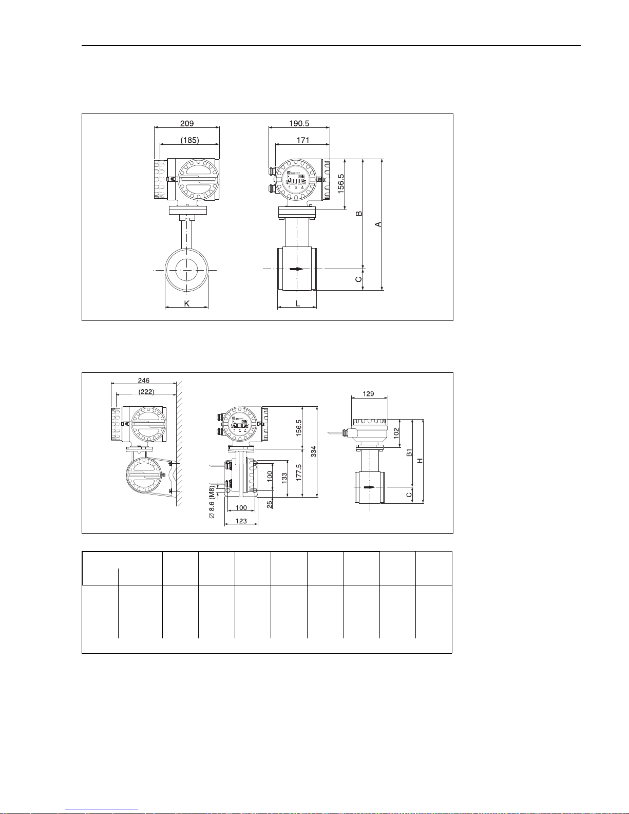
Promag 30 D
Compact version
Remote-mounted version (FS/FL)
Weights
Compact version: see table above
Promag 30 transmitter: 3 kg (5 kg when wall-mounted)
Sensor connection housing: appr. 1 kg
ba008y44
Fig. 47
ba008y45
Fig. 48
DN L K A B B1 C H Weight*
[mm] [inch] [mm] [mm] [mm] [mm] [mm] [mm]
[mm]
[kg]
25
32/40
50
65/80
100
1"
1
1
/4", 11/2"
2"
2
1
/2", 3"
4"
100
100
100
150
150
70
85
100
130
160
345.5
360.5
375.5
405.5
435.5
310.5
318.0
325.5
340.5
355.5
256.0
263.5
271.0
286.0
301.0
35.0
42.5
50.0
65.0
80.0
291.0
306.0
321.0
351.0
381.0
4.0
5.0
5.0
7.5
10.0
* Weight of compact version
Promag 30 7. Technical Data
Endress+Hauser 53
Page 54
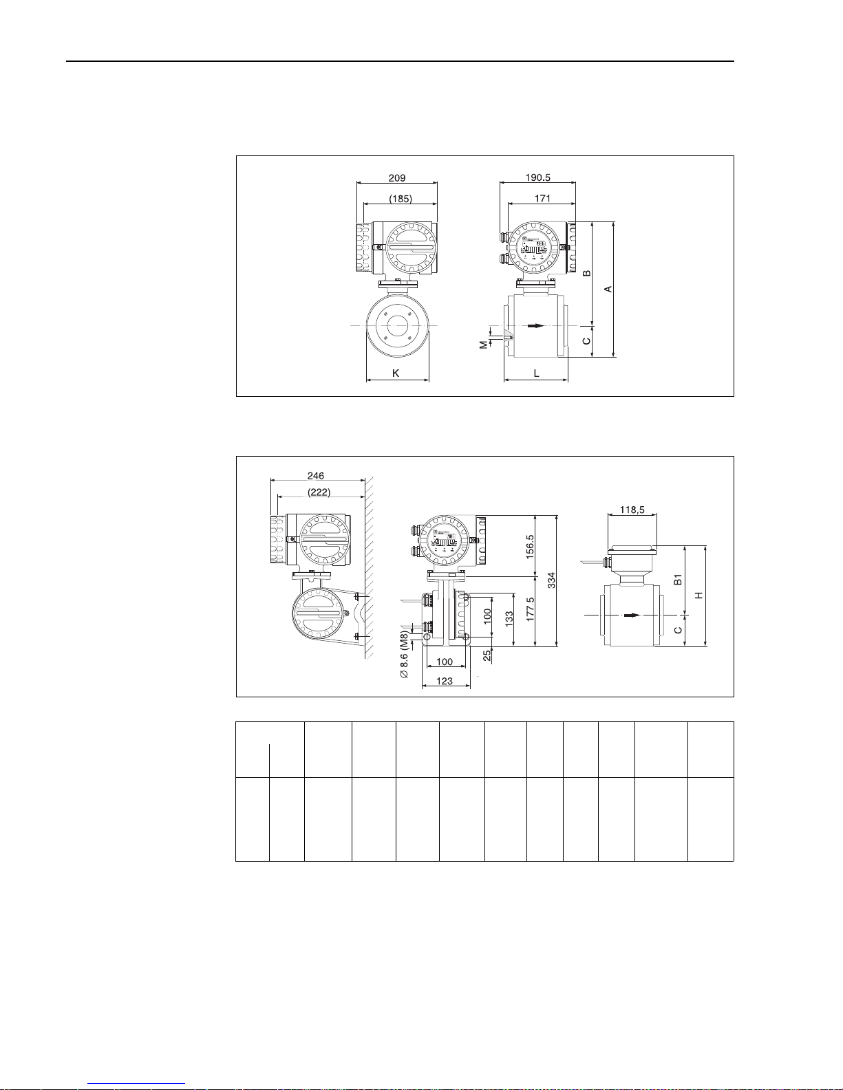
Promag 30 H
Compact version
Remote-mounted version (FS, FL)
Weights
Compact version: see table above
Promag 30 transmitter: 3 kg (5 kg when wall-mounted)
Sensor connection housing: appr. 1 kg
ba008y90
Fig. 49
ba008y91
Fig. 50
DN PN L A B B1 C K H M x X Weight
[mm] [inch] DIN
[bar]
[mm] [mm] [mm] [mm] [mm] [mm] [mm] [mm] [kg]
25
40
50
65
80
100
1"
1
1
/2"
2"
3"
4"
16
16
16
16
16
16
140
140
140
140
200
200
318
318
343
343
393
393
254.0
254.0
266.5
266.5
291.5
291.5
158.5
158.5
171.0
171.0
196.0
196.0
64.0
64.0
76.5
76.5
101.5
101.5
128
128
153
153
203
203
222.5
222.5
247.5
247.5
297.5
297.5
M 6 x 4
M 6 x 4
M 8 x 4
M 8 x 4
M 12 x 4
M 12 x 4
6.0
6.5
9.0
9.0
19.0
18.5
7. Technical Data Promag 30
54 Endress+Hauser
Page 55
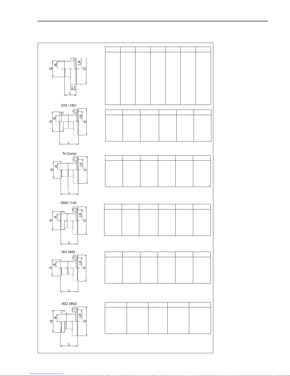
Process connection Promag H
DN D G di L L1 LK
25
25 DIN
40
40 DIN
50
50 DIN
65
65 DIN
80
80 DIN
100
100 DIN
75
79
92
92
105
105
121
121
147
147
168
168
27
31
40
43
55
55
66
72
79
87
104
106
22.6
26
35.3
38
48.1
50
59.9
66
72.6
81
97.5
100
42
42
42
42
42
42
42
42
42
42
42
42
19
19
19
19
19
19
21
21
24
24
24
24
56
60
71
71
83.5
83.5
100
100
121
121
141.5
141.5
DN di G D L LK
25
40
50
65
80
100
26.0
38.0
50.0
66.0
81.0
100.0
52 x
1
/6"
65 x
1
/6"
78 x
1
/6"
95 x
1
/6"
110 x
1
/4"
130 x
1
/4"
79.0
92.0
105.0
121.0
147.0
168.0
68
72
74
78
83
92
56
71
83.5
100
121
141.5
DN di G D L LK
25
40
50
65
80
100
22.1
34.8
47.5
60.2
72.9
97.4
50.4
50.4
63.9
77.4
90.9
118.9
75.0
92.0
105.0
121.0
147.0
168.0
68.6
68.6
68.6
68.6
68.6
68.6
56
71
83.5
100
121
141.5
DN di G D L LK
25
40
50
65
80
100
22.5
35.5
48.5
60.5
72.0
97.6
40 x
1
/6"
60 x
1
/6"
70 x
1
/6"
85 x
1
/6"
98 x
1
/6"
132 x
1
/6"
75.0
92.0
105.0
121.0
147.0
168.0
60
63
65
70
75
70
56
71
83.5
100
121
141.5
DN di G D L LK
25
40
50
65
80
100
22.6
35.6
48.6
60.3
72.9
97.6
50.5
50.5
64.0
77.5
91.0
119.0
75.0
92.0
105.0
121.0
147.0
168.0
68.50
68.50
68.50
68.50
68.50
68.50
56
71
83.5
100
122
141.5
DN di G D L
25
40
50
65
80
100
22.6
35.6
48.6
60.3
72.9
97.6
52 x
1
/6"
65 x
1
/6"
78 x
1
/6"
95 x
1
/6"
110 x
1
/4"
130 x
1
/4"
75.0
92.0
105.0
121.0
147.0
168.0
61.50
61.50
61.50
61.50
61.50
61.50
Length: DN 25... 65 → 2 x L + 136 mm
DN 80... 100 → 2 x L + 196 mm
y45-01
Weld nipples
y45-02
y45-03
y45-04
y45-05
y45-06
Promag 30 7. Technical Data
Endress+Hauser 55
Page 56
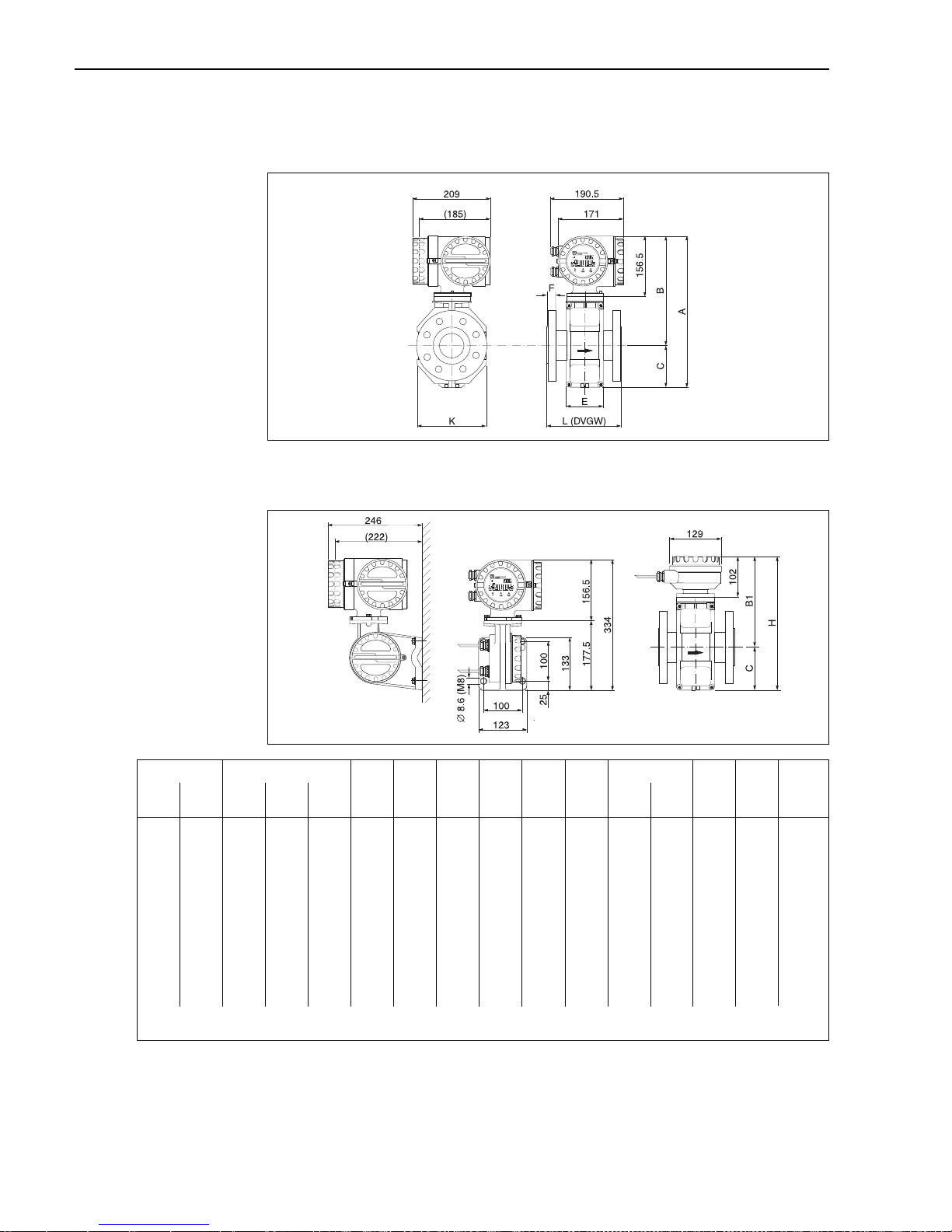
Promag 30 F (DN 15...300)
Compact version
Remote-mounted version (FS/FL)
Weights
Compact version: see table above
Promag 30 transmitter: 3 kg (5 kg when wall-mounted)
Sensor connection housing: appr. 1 kg
ba008y46
Fig. 51
ba008y47
Fig. 52
DN PN L
1
ABCKE F HB1Weight
2
[mm] [inch]
DIN
[bar]
ANSI
[Ibs]
JIS
[mm] [mm] [mm] [mm] [mm] [mm]
DIN
[mm]
ANSI
[mm] [mm] [mm] [kg]
15
25
32
40
50
65
80
100
125
150
200
250
300
1
/2"
1"
-
1
1
/2"
2"
3"
4"
6"
8"
10"
12"
40
40
40
40
40
16
16
16
16
16
10
10
10
150
150
150
150
150
150
150
150
150
150
20K
20K
20K
20K
10K
10K
10K
10K
10K
10K
10K
10K
10K
200
200
200
200
200
200
200
250
250
300
350
450
500
340.5
340.5
340.5
340.5
340.5
390.5
390.5
390.5
471.5
471.5
526.5
576.5
626.5
256.5
256.5
256.5
256.5
256.5
281.5
281.5
281.5
321.5
321.5
346.5
371.5
396.5
84
84
84
84
84
109
109
109
150
150
180
205
230
120
120
120
120
120
180
180
180
260
260
324
400
460
94
94
94
94
94
94
94
94
140
140
156
166
166
14
16
18
18
20
18
20
22
24
24
26
28
28
11.2
14.2
-
17.5
19.1
-
23.9
23.9
-
25.4
28.4
30.2
31.8
286
286
286
286
286
336
336
336
417
417
472
522
572
202
202
202
202
202
227
227
227
267
267
292
317
342
6.5
7.3
8.0
9.4
10.6
12.0
14.0
16.0
21.5
25.5
35.3
48.5
57.5
1
The face-to-face length is identical with the selected nominal diameter and independent of pressure rating.
2
Weight of compact version
7. Technical Data Promag 30
56 Endress+Hauser
Page 57
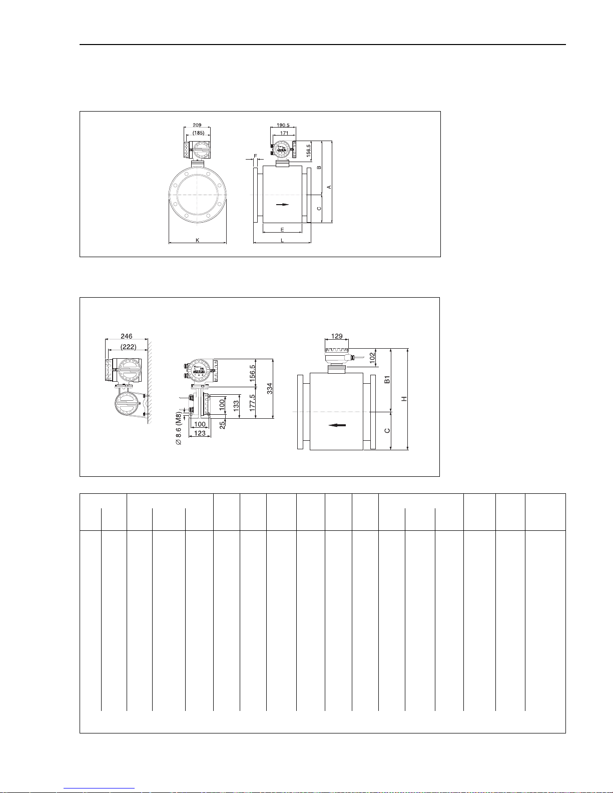
Promag 30 F (DN 350...2000)
Compact version
Remote-mounted version (FS/FL)
ba008y48
Fig. 53
Sensor DN 350...2000
ba008y49
Fig. 54
DN PN L
1
A B C K E F H B1 Weight
2
[mm] [inch]
DIN
[bar]
ANSI
[Class]
AWWA
[Class]
[mm] [mm] [mm] [mm] [mm] [mm] DIN
[mm]
ANSI
[mm]
AWWA
[mm]
[mm] [mm] PN10/ANSI
[kg]
350
400
450
500
600
700
750
800
900
1000
1050
1200
1350
1400
1500
1600
1650
1800
2000
14"
16"
18"
20"
24"
28"
30"
32"
36"
40"
42"
48"
54"
-
60"
66"
72"
78"
10
10
10
10
10
10
10
10
-
6
-
6
-
6
-
6
6
150
150
150
150
150
-
-
-
-
-
-
-
-
-
-
-
-
-
-
-
-
-
-
D
D
D
D
D
D
D
D
D
D
D
D
550
600
650
650
780
910
975
1040
1170
1300
1365
1560
1755
1820
1950
2080
2145
2340
2600
738
790
840
891
995
1198
1198
1241
1394
1546
1598
1796
1998
2148
2196
2286
2360
2550
2650
456
482
507
532.5
584.5
686
686
707.5
784
860
886
985
1086
1161
1185
1230
1267
1362
1412
282
308
333
358.5
410.5
512
512
533.5
610
686
712
811
912
987
1011
1056
1093
1188
1238
564
616
666
717
821
1024
1024
1067
1220
1372
1424
1622
1824
1974
2022
2112
2186
2376
2476
276
276
292
292
402
589
626
647
785
862
912
992
1252
1252
1392
1482
1482
1632
1732
26
26
28
28
30
32
34
34
28
32
34
36
38
34.9
36.5
39.7
42.9
47.6
-
-
-
-
-
-
-
-
-
-
-
-
-
-
-
-
-
-
-
33.3
34.9
38.1
41.3
41.3
44.5
44.5
54.0
-
57,2
-
63.5
66.7
69.9
683.5
735.5
785.5
836.5
940.5
1143.5
1143.5
1186.5
1339.5
1491.5
1543.5
1741.5
1943.5
2093.5
2141.5
2231.5
2305.5
2495.5
2595.5
401.5
427.5
452.5
478
530
631.5
631.5
653
729.5
805.5
831.5
930.5
1031.5
1106.5
1130.5
1175.5
1212.5
1307.5
1357.5
110
130
240
170
230
350
450
450
600
720
1050
1200
2150
1800
2600
2500
3700
3300
4100
1
The face-to-face length is identical with the selected nominal diameter and independent of pressure rating.
2
Weight of compact version
Promag 30 7. Technical Data
Endress+Hauser 57
Page 58
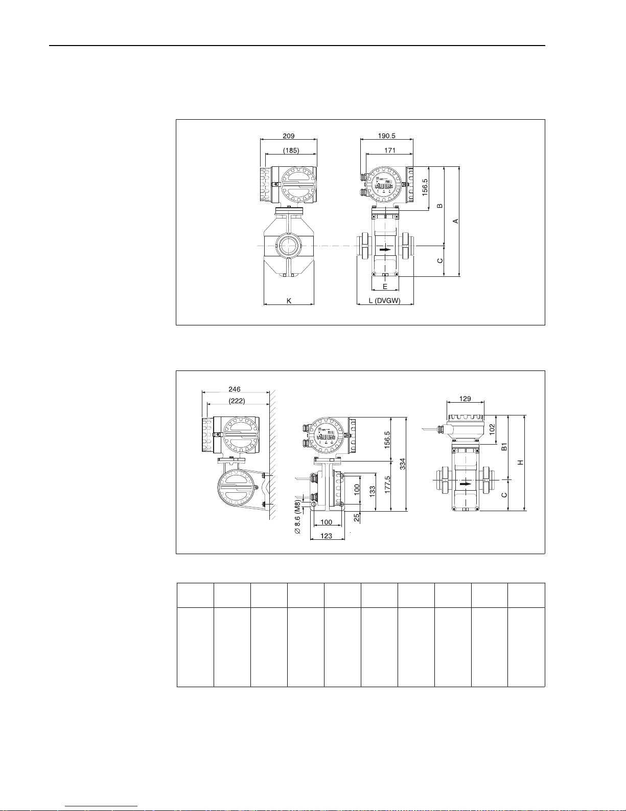
Promag 30 F with DIN 11851 couplings
Compact version
Remote-mounted version (FS/FL)
ba008y92
Fig. 55
ba008y93
Fig. 56
DN
[mm]L[mm]A[mm]B[mm]B1[mm]C[mm]K[mm]E[mm]H[mm]
Weight
15
25
32
40
50
65
80
100
200
200
200
200
200
200
200
250
340.5
340.5
340.5
340.5
340.5
390.5
390.5
390.5
256.5
256.5
256.5
256.5
256.5
281.5
281.5
281.5
202
202
202
202
202
227
227
227
84
84
84
84
84
109
109
109
120
120
120
120
120
180
180
180
94
94
94
94
94
94
94
94
286
286
286
286
286
336
336
336
6.5
7.3
8.0
9.4
10.6
12.0
14.0
16.0
7. Technical Data Promag 30
58 Endress+Hauser
Page 59

7.2 Technical data: Sensor
Promag A Promag D
Nominal diameter
DN 2, 4, 8, 15, 25 DN 25...100
Nominal pressure
PN 40 PN 40
Process connection
Internal and external thread, PVC
adhesive coupling, hose connection,
welded nipple, aseptic welded nipple
according to DIN 11850, Tri-Clamp,
Flange connection (DIN, ANSI, JIS)
Wafer
Tri-Clamp (optional)
Hygienic couplings
acc. to DIN 11851 (optional)
Flange material
DIN: stainless steel 1.4404;
PVDF
ANSI: 316L; PVDF
JIS: 316L; PVDF
Threaded stub: 1.4435; PVC
—
Fluid temperature range
and liner material
–20...+130 °C PFA –40...+150 °C PTFE
–20...+120 °C soft rubber
0...+ 80 °C hard rubber
Ambient temperature
range
–20...+60 °C –20...+ 60 °C
Electrode material
1.4435, Platinum/Rhodium 80/20,
Titanium, Hastelloy C-22, Tantalum
1.4435, Platinum/Rhodium 80/20,
Titanium, Hastelloy C-22, Tantalum
Electrodes fitted
Measuring and reference electrodes
Option: Measuring, reference and empty
pipe detection electrodes
Measuring and reference electrodes
Option: Measuring, reference and empty
pipe detection electrodes
Min. conductivity
5 µS/cm 5 µS/cm
Gasket material
Viton, Kalrez (optional)
Silicon (aseptic version)
—
Housing material
1.4435 incl. threaded stub
(see also dimensions on page 52)
Varnished steel
(Option: stainless steel)
Type of protection
IP 67 (IP 68 option)
NEMA 4X (NEMA 6P as option)
IP 67 (IP 68 option)
NEMA 4X (NEMA 6P as option)
Suitable for cleaning
with CIP
Yes (note max. temperature) Yes (note max. temperature)
Suitable for cleaning
with SIP
——
Power Supply
The sensor is supplied by the measuring transmitter
Explosion protected
version
CENELEC: EEx d/de;
Ex Zone 2 VDE 0165
FM/CSA: Class I, Div. 1
FM/CSA: Class I, Div. 2
SEV: EEx d/de
SEV: Ex n
others in preparation
Ex Zone 2 VDE 0165
FM/CSA: Class I, Div. 2
Approvals
——
Cable entries
(Remote-mounted
version)
PG 11 cable glands (5...12 mm) or
NPT
1
/2", M20 x 1.5 (8…15 mm),
G
1
/2" threads for cable glands
PG 13.5 cable glands (5…15 mm) or
NPT
1
/2", M20 x 1.5 (8…15 mm),
G
1
/2" threads for cable glands
Promag 30 7. Technical Data
Endress+Hauser 59
Page 60

Promag H Promag F
Nominal diameter DN 25...100 DN 25...2000
Nominal pressure
PN 16 DIN: PN 6 (DN 1200…2000)
PN 10 (DN 200...1000)
PN 16 (DN 65...150)
PN 40 (DN 25...50)
PN 16 /25 (DN 200...300),
Option
PN 40 (DN 65...100), Opt.
ANSI: Class 150 (1...24")
Class 300 (1...6"), Opt.
AWWA: Class D (28...48")
JIS: 10K (DN 50...300)
20K (DN 25...40)
20K (DN 50...300), Opt.
Process connection
Weld nipples for OD tube,
SMS, JIS, ISO and DIN 11850 tubes.
DIN 11851 thread. SMS thread.
ISO 2853 thread. Tri-Clamp.
ISO 2852.
Flange connection (DIN, ANSI, JIS)
Hygienic couplings acc. to DIN 11851
(DN 15...100)
Flange material 1.4435/316L DIN: St. 37.2,
stainless steel1.4571
ANSI: A105, 316L
AWWA: A105, A36
JIS: S20C, SUS 316L
Fluid temperature range,
liner material
–20 °C...+150 °C (PFA)
–20...+130 °C (with EPDM gaskets)
DN 15...600:
–40...+130 °C (PTFE)
DN 25...2000:
–20...+120 °C (Soft rubber)
DN 65...2000:
0...+80 °C (Hard rubber)
Ambient temperature
range
–20...+60 °C –20...+60 °C
Electrode material
1.4435 1.4435, Platinum/Rhodium 80/20,
Hastelloy C-22, Tantalum
Electrodes fitted Measuring and empty pipe
detection electrodes
DN 15...2000: Measuring, reference and
EPD electrodes (standard for 1.4435 and
Hastelloy C-22)
Min. conductivity
5 µS/cm 5 µS/cm
Gasket material
EPDM, Silicone —
Housing material 1.4301 DN 25...300: powder-coated die-cast
aluminium
DN 350...2000: varnished steel
Type of protection
IP 67
NEMA 4X
IP 67 (IP 68 option)
NEMA 4X (NEMA 6P as option)
CIP cleanable Yes (note max. temperature) Yes (note max. temperature)
SIP cleanable
Yes (note max. temperature) —
Power Supply The sensor is supplied by the measuring transmitter
Explosion protected
version
Ex Zone 2 VDE 0165
FM/CSA: Class I, Div. 2
CENELEC: EEx d/de;
Ex Zone 2 VDE 0165
FM/CSA: Class I, Div. 2
FM/CSA: Class I, Div. 1
SEV: EEx d/de
SEV: Ex n
others in preparation
Approvals EHEDG tested
3A approval
—
Cable entries
(Remote-mounted
version)
PG 13.5 cable glands (5...15 mm) or
NPT
1
/2", M20 x 1.5 (8...15 mm),
G
1
/2" threads for cable glands
PG 13.5 cable glands (5...15 mm) or
NPT
1
/2", M20 x 1.5 (8...15 mm),
G
1
/2" threads for cable glands
7. Technical Data Promag 30
60 Endress+Hauser
Page 61

Inside diameter of measuring pipe [mm]
Sensor DN PN Inside diameter of measuring pipe
in mm, lining
[mm] [inch] DIN [bar] ANSI [lbs] JIS AWWA PFA PTFE
(Teflon)
Hard rubber,
Soft rubber
(EPDM)
Promag A
2
4
8
15
25
1
/12"
5
/32"
5
/16"
1
/2"
1"
40/16 Class
150/300
10K/20K
–
–
–
–
–
2.2
4.6
8.6
16.1
22.0
–
–
–
–
–
–
–
–
–
–
Promag D
25
32
40
50
65
80
100
1"
–
1
1
/2"
2"
–
3"
4"
40
–
–
–
–
–
–
–
–
–
–
–
–
–
–
–
–
–
–
–
–
–
–
–
–
–
–
–
–
26
35
41
51
67
79
103
24
32
37
48
64
77
98
Promag H
25 DIN
25
40
50
65
80
100
-
1"
1
1
/2"
2"
2
1
/2"
3"
4"
16
–
–
–
–
–
–
–
–
–
–
–
–
–
–
–
–
–
–
–
–
–
26.0
22.6
35.3
48.1
59.9
72.6
97.5
–
–
–
–
–
–
–
–
–
–
–
–
–
–
Promag F
15
25
32
40
50
65
80
100
125
150
200
250
300
–
400
–
500
600
700
–
800
900
1000
–
1200
–
1400
–
1600
–
1800
–
2000
1
/2"
1"
–
1
1
/2"
2"
–
3"
4"
–
6"
8"
10"
12"
14"
16"
18"
20"
24"
28"
30"
32"
36"
40"
42"
48"
54"
–
60"
–
66"
72"
78"
–
40
40
40
40
40
16
16
16
16
16
10
10
10
10
10
–
10
10
10
–
10
10
10
–
6
–
6
–
6
–
6
–
6
Class 150
Class 150
–
Class 150
Class 150
–
Class 150
Class 150
–
Class 150
Class 150
Class 150
Class 150
Class 150
Class 150
Class 150
Class 150
Class 150
–
–
–
–
–
–
–
–
–
–
–
–
–
–
–
20K
20K
20K
20K
10K
10K
10K
10K
10K
10K
10K
10K
10K
–
–
–
–
–
–
–
–
–
–
–
–
–
–
–
–
–
–
–
–
–
–
–
–
–
–
–
–
–
–
–
–
–
–
–
–
–
–
Class D
Class D
Class D
Class D
Class D
Class D
Class D
Class D
–
Class D
–
Class D
Class D
Class D
–
–
–
–
–
–
–
–
–
–
–
–
–
–
–
–
–
–
–
–
–
–
–
–
–
–
–
–
–
–
–
–
–
–
15
26
35
41
52
68
80
105
130
156
207
259
309
337
387
–
487
593
–
–
–
–
–
–
–
–
–
–
–
–
–
–
–
–
–
–
–
–
65
78
100
126
154
205
259
310
341
391
436
491
593
692
741
794
893
995
1042
1195
1338
1401
1491
1599
1637
1799
1981
1995
Promag 30 7. Technical Data
Endress+Hauser 61
Page 62
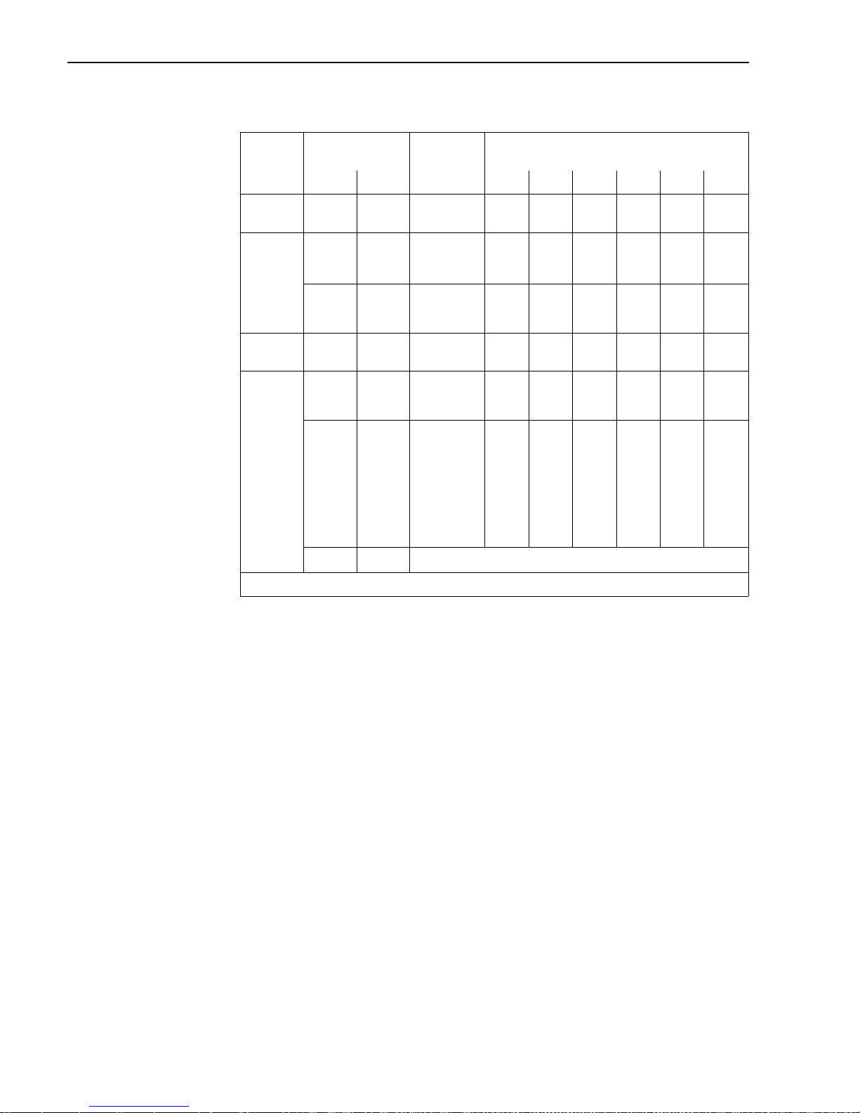
Resistance of the lining to vacuum (Standard version)
Sensor DN Lining Limits for vacuum [mbar abs]
at different medium temperatures
[mm] [inch] 25 °C 80 °C 100 °C 120 °C 130 °C 150 °C
Promag A
2...25
1
/12...1" PFA 0 0000
Promag D
25...100
25...100
1...4"
1...4"
Hard rubber,
Soft rubber
(EPDM)
0
0
0
000
25... 50
65... 80
100
1...2"
3"
4"
PTFE
(Teflon)
0
0
0
0
✶
✶
0
40
130
✶
✶
✶
✶
✶
✶
110
130
170
Promag H
25...100 1...4" PFA 0 00000
Promag F
65...1200
25...1200
3...78"
1...78"
Hard rubber,
Soft rubber
(EPDM)
0
0
0
000
15... 50
65... 80
100
125...150
200
250
300
350
400
1
/2...2"
3"
4"
6"
8"
10"
12"
14"
16"
PTFE
(Teflon)
0
0
0
135
200
330
400
470
540
0
✶
✶
✶
✶
✶
✶
✶
✶
0
40
135
240
290
400
500
600
670
✶
✶
✶
✶
✶
✶
✶
✶
✶
100
130
170
385
410
530
630
730
800
450...600 18...24" Vacuum not permitted!
✶
Values not available
7. Technical Data Promag 30
62 Endress+Hauser
Page 63
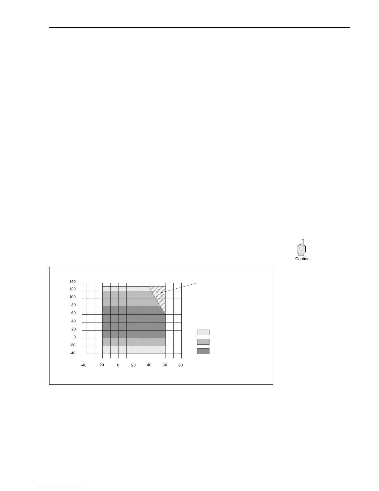
Temperature ranges of sensors
The maximum permissible ambient and medium temperatures must be adhered to at
all times. When installed outdoors, specially in countries with high ambient
temperatures please provide a weatherproof hood as protection against direct solar
radiation.
• Promag A
Ambient temperature: –20...+ 60 °C
Medium temperature: –20...+130 °C PFA
• Promag D
Ambient temperature: –20...+ 60 °C
Medium temperature: –40...+150 °C PTFE (Teflon)
–20...+120 °C soft rubber (EPDM)
0...+ 80 °C hard rubber
• Promag H
Ambient temperature: –20... + 60 °C
Medium temperature: –20... +150 °C PFA
–20... +130 °C with EPDM gaskets
• Promag F
Ambient temperature: –20... + 60 °C
Medium temperature: –40... +130 °C PTFE (Teflon)
–20... +120 °C soft rubber (EPDM)
0... + 80 °C hard rubber
Caution!
At high medium and ambient temperatures it is necessary to mount the Promag F, H
sensor and Promag 30 transmitter separately. Risk of the electronics becoming
over-heated (Fig. 57)!
Ambient temperature [°C]
Medium temperature [°C]
Temperature range available
only for remote-mounted
version
ba008y50
PTFE (Teflon)
soft rubber
(EPDM)
hard rubber
Fig. 57:
Limits of application in terms
of temperature for compact
version and lining
Promag 30 7. Technical Data
Endress+Hauser 63
Page 64
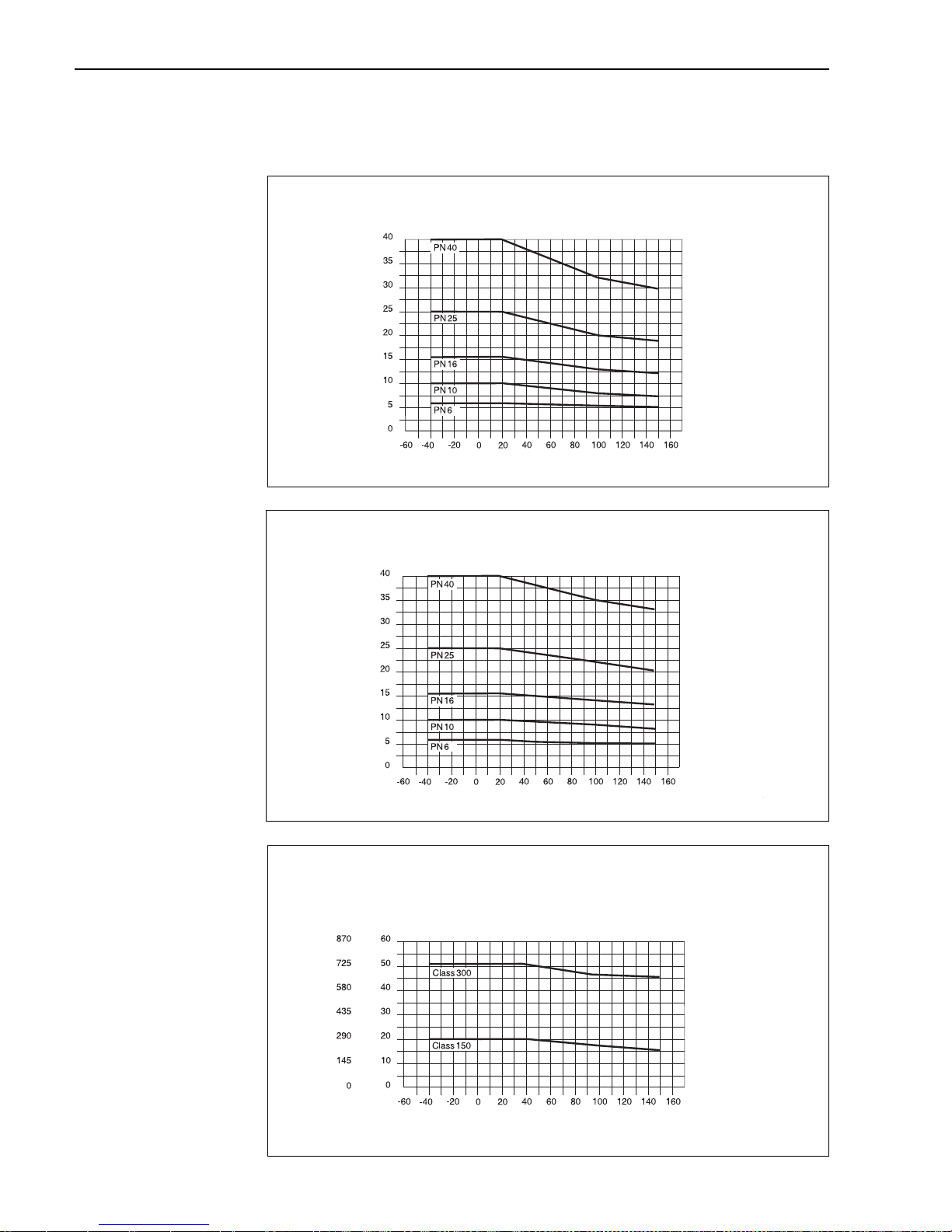
Pressure limitations
Promag F sensor (flange-mounted)
Temperature [°C]
Pressure [bar]
ba008y51
Pressure limitations due to fluid temperature (DIN 2413 and 2505)
Flange material: steel 37.2
Fig. 58
Temperature [°C]
Pressure [bar]
ba008y52
Pressure limitations due to fluid temperature (DIN 2413 and 2505)
Flange material: stainless steel 1.4571
Fig. 59
Temperature [°C]
Pressure [psi]
ba008y53
Pressure [bar]
Pressure limitations due to fluid temperature (ANSI B16.5)
Flange material: steel A 105
Fig. 60
7. Technical Data Promag 30
64 Endress+Hauser
Page 65
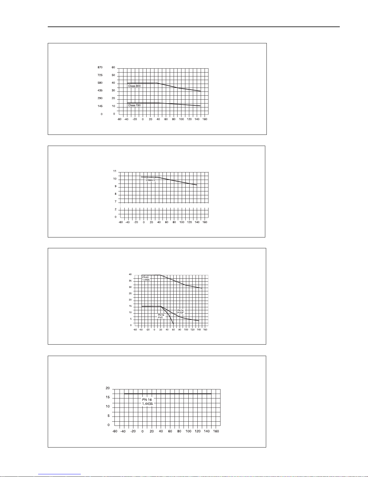
Temperature [°C]
Pressure [psi]
ba008y54
Pressure [bar]
Pressure limitations due to fluid temperature (ANSI B 16.5)
Flange material: steel 316L
Fig. 61
Temperature [°C]
Pressure [bar]
ba008y55
Pressure limitations due to fluid temperature (AWWA C207, Class D)
Flange material: steel A105
Fig. 62
Temperature [°C]
Pressure [bar]
ba008y56
Promag A sensor
Pressure limitations due to fluid temperature
Flange material: steel 1.4404/1.4435, PVDF, PVC
Fig. 63
Temperature [°C]
Pressure [bar]
ba008y56
Promag H sensor
Pressure limitations due to fluid temperature
Flange material: steel 1.4435
Fig. 64
Promag 30 7. Technical Data
Endress+Hauser 65
Page 66

7.3 Technical data: Transmitter and measuring system
Promag 30 transmitter/measuring system
Housing material Powder-coated die-cast aluminium
Protection IP 67 (EN 60529); NEMA 4X
Ambient temperature -20...+60 °C
Resistance to shock
and vibration
Acceleration up to 2 g/2 h per day; 10...100 Hz
(complete measuring system)
Cable entries Power supply cable and signal cable (inputs/outputs)
PG 13.5 cable glands (5...15 mm) or NPT
1
/
2",
M20 x 1.5
(8...15 mm), G1/2" threads for cable glands
Coil cable and signal cable (remote-mounted version):
PG 13.5 cable glands (5...15 mm) or NPT
1
/
2",
M20 x 1.5
(8...15 mm), G
1
/2" threads for cable glands
Power supply 85...260 V AC, 45...65 Hz
20... 55 V AC, 16...62 V DC
Supply failure: Bridging over min. 1 mains cycle (22 ms)
Power consumption AC: <15 VA (incl. sensor)
DC: <15 W (incl. sensor)
Galvanic separation Input and output galvanically separated from supply, from sensor
and from one another
Full-scale value scaling 0.4...10 m/s
Current output 0/4...20 mA adjustable, galvanically separated, R
L
<700 Ω,
Time constant: automatically assigned full-scale value can be set,
Temperature coefficient: 0.01 % o.r./°C, additional error: 0.3 % o.r.
Pulse output
(open collector)
f
max
= 400 Hz, U
max
30 V, I
max
250 mA, galvanically separated,
pulse value adjustable, pulse/pause ratio appr. 1:1, pulse width max. 2 s,
Status output
(open collector)
U
max
30 V, I
max
250 mA; Adjustable for: System and process error
messages, Flow direction recognition
Auxiliary input
(Measured value
suppression)
U = 3...30 V DC, R
i
= 1.8 kΩ, galvanically separated
Adjustable for measured value suppression or external totaliser reset
(if instrument fitted with display).
Compatibility with
interference (EMC)
As per EN 50081 Part 1 and 2 / EN 50082 Part 1 and 2, and NAMUR
recommendations (complete measuring system)
Explosion protected
version
Compact and remote versions for:
CENELEC: EEx d/de;
Ex-Zone 2 VDE 0165
FM/CSA: Class I, Div. 1
FM/CSA: Class I, Div. 2
SEV: EEx d/de
SEV: Ex n
others in preparation
7. Technical Data Promag 30
66 Endress+Hauser
Page 67

7.4 Nominal diameter and flow rate
As a rule the pipe diameter governs the nominal diameter of the sensor. When the
volume flow is known, it is possible to estimate from the table below whether the
optimal velocity range of 2...3 m/s can be adhered to.
The flow velocity (v) also has to matched to the physical properties of the medium:
• v < 2 m/s: with abrasive media (potter’s clay, lime milk, or slurry)
• v > 2 m/s: with media forming a coating (waste-water sludge, etc.)
If it is necessary to increase the flow velocity, this can be done by reducing the
nominal diameter of the sensor (see chapter 3.3 “Adaptors”).
The table below summarizes the minimum and maximum full-scale values (incl. works
setting) which can be set by miniature switches in Promag 30.
DN Minimum
full-scale value
Full-scale values
works settings
Maximum
full-scale value
[mm] [inch] (Scaling at
v ~ 0.5 m/s)
(Scaling at
v ~ 2.5 m/s)
(Scaling at
v ~10 m/s)
2
4
8
15
25
32
40
50
65
80
100
125
150
200
250
300
350
400
450
500
600
700
800
900
1000
1200
1400
1600
1800
2000
1
/12"
5
/32"
5
/16"
1
/2"
1"
1
1
/4"
1
1
/2"
2"
2
1
/2"
3"
4"
5"
6"
8"
10"
12"
14"
16"
18"
20"
24"
28"
32"
36"
40"
48"
56"
64"
72"
78"
0.005 m
3
/h
0.02 m
3
/h
0.1 m
3
/h
0.3 m
3
/h
1 m
3
/h
1.5 m
3
/h
2 m
3
/h
4 m
3
/h
6 m
3
/h
10 m
3
/h
15 m
3
/h
20 m
3
/h
30 m
3
/h
50 m
3
/h
100 m
3
/h
150 m
3
/h
200 m
3
/h
200 m
3
/h
300 m
3
/h
400 m
3
/h
600 m
3
/h
800 m
3
/h
1000 m
3
/h
1000 m
3
/h
1500 m
3
/h
2000 m
3
/h
3000 m
3
/h
4000 m
3
/h
5000 m
3
/h
5000 m
3
/h
0.025m
3
/h
0.1 m
3
/h
0.5 m
3
/h
1.5 m
3
/h
5 m
3
/h
7.5 m
3
/h
10 m
3
/h
20 m
3
/h
30 m
3
/h
50 m
3
/h
75 m
3
/h
100 m
3
/h
150 m
3
/h
250 m
3
/h
500 m
3
/h
750 m
3
/h
1000 m
3
/h
1000 m
3
/h
1500 m
3
/h
2000 m
3
/h
3000 m
3
/h
4000 m
3
/h
5000 m
3
/h
5000 m
3
/h
7500 m
3
/h
10000 m
3
/h
15000 m
3
/h
20000 m
3
/h
25000 m
3
/h
25000 m
3
/h
0.1 m
3
/h
0.4 m
3
/h
2m
3
/h
6m
3
/h
20 m
3
/h
30 m
3
/h
40 m
3
/h
80 m
3
/h
120 m
3
/h
200 m
3
/h
300 m
3
/h
400 m
3
/h
600 m
3
/h
1000 m
3
/h
2000 m
3
/h
3000 m
3
/h
4000 m
3
/h
4000 m
3
/h
6000 m
3
/h
8000 m
3
/h
12000 m
3
/h
16000 m
3
/h
20000 m
3
/h
20000 m
3
/h
30000 m
3
/h
40000 m
3
/h
60000 m
3
/h
80000 m
3
/h
100000 m
3
/h
100000 m
3
/h
Promag 30 7. Technical Data
Endress+Hauser 67
Page 68
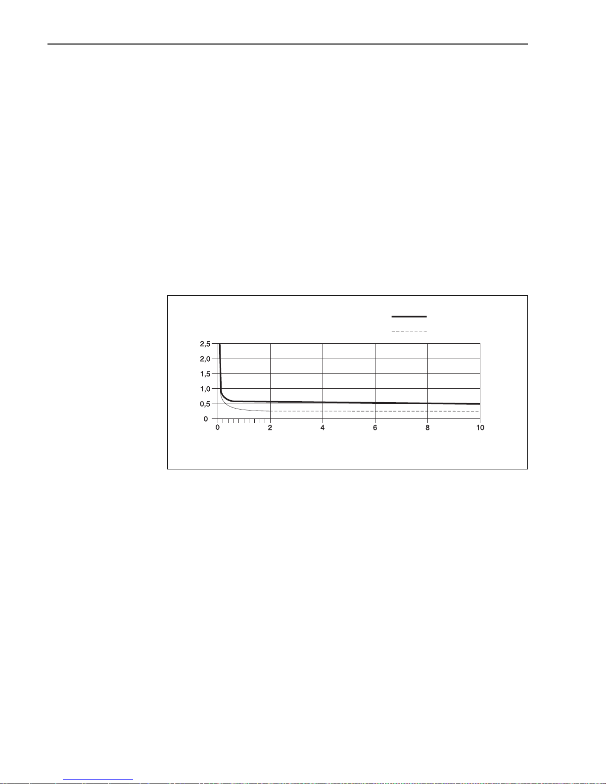
7.5 Error limits
Measuring uncertainty under reference conditions
Pulse output ± 0.5% o .r. ± 0.01% o.f.s. (full-scale value = 10 m/s)
(Promag 30 D: plus ± 0.2% o.r.)
Current output plus typ. ±10 µA
Repeatability ± 0.1% o.r. ± 0.005% o.f.s.
Options Promag 30 A and F: ± 0.2% o.r. ± 0.05% of Q
k
Promag 30 D: ± 0.45% o.r. ± 0.05% of Q
k
Qk = desired reference flow rate for
calibration (v = 2...10 m/s).
Please quote Q
k
when ordering
Power supply voltage Within the specified range, fluctuation of
the supply voltage has no effect.
Reference conditions (DIN 19200 and VDI/VDE 2641)
Medium temperature +28 °C ± 2 K
Ambient temperature +22 °C ± 2 K
Heating-up time 30 minutes
Installation at inlet length >10 x DN
reference conditions outlet length >5 x DN
Sensor and transmitter are earthed.
The sensor is mounted centrally in the pipe.
Medium velocity
[m/s]
Error [% o.r.]
ba008y59
0.5%
0.2% (option)
Fig. 65
7. Technical Data Promag 30
68 Endress+Hauser
Page 69

Index
A
Adaptor pieces . . . . . . . . . . . . . . 17
Auxiliary input (configuration) . . . . . . . 36, 43
B
Bidirectional measurement . . . . . . . . . . 35
Boards (power supply, amplifier) . . . . . . . 48
C
Cable length (remote version) . . . . . . . . 24
Cable specifications . . . . . . . . . . . . 31
Cathodic protection . . . . . . . . . . . . 25
Commissioning . . . . . . . . . . . . . . 44
Conductivity of the medium . . . . . . . . . 24
Correct usage . . . . . . . . . . . . . . . 5
Creep suppression . . . . . . . . . . . . . 33
Current range . . . . . . . . . . . . . . . 35
D
Data storage (DAT) . . . . . . . . . . . . . 11
Diagnosis and troubleshooting . . . . . . . . 45
Dimensions . . . . . . . . . . . . . . . . 51
Display (configuration) . . . . . . . . . . . 42
Display (turning) . . . . . . . . . . . . . . 23
Display functions . . . . . . . . . . . . . 43
Display segments . . . . . . . . . . . . . 42
Dynamic response . . . . . . . . . . . . . 11
E
Earthing discs . . . . . . . . . . . . . . . 25
ECC (Electrode cleaning circuit) . . . . . . . 36
Electrical connection . . . . . . . . . . . . 27
Electrical connection (remote version) . . . 28, 30
Electrode axis . . . . . . . . . . . . . . . 15
Electrode cleaning (ECC) . . . . . . . . . . 36
Electromagnetic compatibility (EMC) . . . . 26, 31
Empty pipe detection (EPD) . . . . . . . . . 16
Error limits (measuring uncertainty) . . . . . . 68
Error messages (display segements) . . . . . . 45
Error messages (status output) . . . . . . . . 34
Ex versions (documentation) . . . . . . . . . 2
F
Farady’s law of induction . . . . . . . . . . 7
Fault location and remedies . . . . . . . 45, 46
Fields of application . . . . . . . . . . . . 7
Flow direction (status output) . . . . . . . . . 34
Flow direction (uni/bidirectional) . . . . . . . . 35
Flow rate/Nominal diameter . . . . . . . . . 67
Flow velocity . . . . . . . . . . . . . . . 67
Full-scale value . . . . . . . . . . . . . . 36
Full-scale values (settings) . . . . . . . . . . 40
G
Gaskets . . . . . . . . . . . . . 13, 18, 19, 21
Grounding (potential equalisation) . . . . . . 25
Grounding discs . . . . . . . . . . . . . 25
Grounding with severe electrical interference . . 26
I
Instrument functions (description) . . . . . . 33
Instrument functions (setting with switches) . . . 37
L
Lining (vacuum resistance) . . . . . . . . . 62
Load diagrams (pressure, temperature) . . . . 64
M
Measured value suppression . . . . . . . . 36
Measuring electrodes (replacing) . . . . . . . 22
Measuring pipe (inside diameter) . . . . . . . 61
Measuring principle . . . . . . . . . . . . . 7
Measuring system (design) . . . . . . . . . 10
Memory (DAT) . . . . . . . . . . . . . . 11
Minimum conductivity . . . . . . . . . . . . 7
Mounting and Installation . . . . . . . . . . 13
Mounting location . . . . . . . . . . . . . 16
Mounting position . . . . . . . . . . . . . 15
Mounting set (Promag D sensor) . . . . . . . 19
Mounting the sensor . . . . . . . . . . . . 18
Mounting the transmitter (remote version) . . . 24
N
Nominal diameter and flow rate . . . . . . . 67
O
Operating keys (display) . . . . . . . . . . 42
Operation . . . . . . . . . . . . . . . . 10
Operation (display) . . . . . . . . . . . . 42
Operation (instrument functions) . . . . . . . 37
P
Potential equalisation . . . . . . . . . . . 25
Pressure limitations due to fluid temperature . . 64
Pressure loss (adapter pieces) . . . . . . . . 17
Process connections (DIN 11851 couplings) . . 58
Process connections (Promag A sensor) . . . 18, 52
Process connections (Promag H sensor) . . . 20, 55
Promag measuring system . . . . . . . . . . 8
Protection IP 67 . . . . . . . . . . . . . . 13
Pulse value . . . . . . . . . . . . . . . 35
Pulse value (settings) . . . . . . . . . . . 38
Pulse width . . . . . . . . . . . . . . . 35
Pumps (mounting location) . . . . . . . . . 17
Promag 30 Index
Endress+Hauser 69
Page 70

R
Reference electrode . . . . . . . . . . . . 25
Remote version (electrical connection) . . . 28, 30
Remote version (mounting) . . . . . . . . . . 24
Repairs . . . . . . . . . . . . . . . . 6, 49
Replacing measuring electrodes . . . . . . . 22
Replacing the transmitter electronics . . . . . . 47
S
Safety . . . . . . . . . . . . . . . . . . 11
Safety instructions . . . . . . . . . . . . 5, 6
Screw tightening torques (Promag D sensor) . . . 19
Screw tightening torques (Promag F sensor) . . . 21
Screw tightening torques (Promag H sensor) . . . 20
SI units . . . . . . . . . . . . . . . . . 37
Status output (configuration, behaviour) . . . . . 34
System error (status output) . . . . . . . . . 34
System units (SI/US) . . . . . . . . . . . . 37
T
Technical data . . . . . . . . . . . . . . . 51
Technical data (sensor) . . . . . . . . . . . 59
Technical data (transmitter) . . . . . . . . . 66
Temperature ranges (sensor) . . . . . . . . . 63
Temperature ranges (transmitter) . . . . . . . 66
Totaliser display . . . . . . . . . . . . . . 43
Totaliser overrun . . . . . . . . . . . . . . 43
Totaliser reset (via auxiliary input) . . . . . . . 43
Transmitter housing (turning) . . . . . . . . . 23
Transport instructions for sensor DN 350/14" . . . 14
Troubleshooting . . . . . . . . . . . . 45, 46
Type of fault . . . . . . . . . . . . . . . . 45
U
Unidirectional measurement . . . . . . . . . 35
Units (SI/US) . . . . . . . . . . . . . . . 37
US units . . . . . . . . . . . . . . . . . 37
V
Vibration . . . . . . . . . . . . . . . . . 15
W
Weights . . . . . . . . . . . . . . . . . 51
Wiring diagrams . . . . . . . . . . . . 29, 30
Works settings (instrument functions) . . . . . . 37
Index Promag 30
70 Endress+Hauser
Page 71

Page 72

Europe
Aust ria
❑ Endress+Hauser Ges.m.b.H.
Wien
Tel. (01) 88056-0, Fax (01) 88056-35
Belarus
❑ Belorgsintez
Minsk
Tel. (0172) 508473, Fax (0172) 508583
Belgium / Luxembourg
❑ Endress+Hauser N.V.
Brussels
Tel. (02) 2480600, Fax (02) 2480553
Bulgaria
INTERTECH-AUTOMATION
Sofia
Tel. (02) 664869, Fax (02) 9631389
Croatia
❑ Endress+Hauser GmbH+Co.
Zagreb
Tel. (01) 6637785, Fax (01) 6637823
Cyprus
I+G Electrical Services Co. Ltd.
Nicosia
Tel. (02) 484788, Fax (02) 484690
Czech Republic
❑ Endress+Hauser GmbH+Co.
Praha
Tel. (026) 6784200, Fax (026) 6784179
Denmark
❑ Endress+Hauser A/S
Søborg
Tel. (70) 131132, Fax (70) 132133
Estonia
ELVI-Aqua
Tartu
Tel. (7) 441638, Fax (7) 441582
Finland
❑ Endress+Hauser Oy
Helsinki
Tel. (0204) 83160, Fax (0204) 83161
France
❑ Endress+Hauser S.A.
Huningue
Tel. (389) 696768, Fax (389) 694802
Germany
❑ Endress+Hauser Messtechnik GmbH+Co.
Weil am Rhein
Tel. (07621) 975-01, Fax (07621) 975-555
Great Britain
❑ Endress+Hauser Ltd.
Manchester
Tel. (0161) 2865000, Fax (0161) 9981841
Greece
I & G Building Services Automation S.A.
Athens
Tel. (01) 9241500, Fax (01) 9221714
Hungary
Mile Ipari-Elektro
Budapest
Tel. (01) 4319800, Fax (01) 4319817
Iceland
BIL ehf
Reykjavik
Tel. (05) 619616, Fax (05) 619617
Ireland
Flomeaco Company Ltd.
Kildare
Tel. (045) 868615, Fax (045) 868182
Italy
❑ Endress+Hauser S.p.A.
Cernusco s/N Milano
Tel. (02) 921921, Fax (02) 92107153
Latvia
Rino TK
Riga
Tel. (07) 315087, Fax (07) 315084
Lithuania
UAB "Agava"
Kaunas
Tel. (07) 202410, Fax (07) 207414
Netherland
❑ Endress+Hauser B.V.
Naarden
Tel. (035) 6958611, Fax (035) 6958825
Norway
❑ Endress+Hauser A/S
Tranby
Tel. (032) 859850, Fax (032) 859851
Poland
❑ Endress+Hauser Polska Sp. z o.o.
Warszawy
Tel. (022) 7201090, Fax (022) 7201085
Portugal
Tecnisis, Lda
Cacém
Tel. (21) 4267290, Fax (21) 4267299
Romania
Romconseng S.R.L.
Bucharest
Tel. (01) 4101634, Fax (01) 4112501
Russia
❑ Endress+Hauser Moscow Office
Moscow
Tel. (095) 1587564, Fax (095) 1589871
Slovakia
Transcom Technik s.r.o.
Bratislava
Tel. (7) 44888684, Fax (7) 44887112
Slovenia
❑ Endress+Hauser D.O.O.
Ljubljana
Tel. (061) 5192217, Fax (061) 5192298
Spain
❑ Endress+Hauser S.A.
Sant Just Desvern
Tel. (93) 4803366, Fax (93) 4733839
Sweden
❑ Endress+Hauser AB
Sollentuna
Tel. (08) 55511600, Fax (08) 55511655
Switzerland
❑ Endress+Hauser AG
Reinach/BL 1
Tel. (061) 7157575, Fax (061) 7111650
Tur ke y
Intek Endüstriyel Ölcü ve Kontrol SistemleriIstanbul
Tel. (0212) 2751355, Fax (0212) 2662775
Ukraine
Photonika GmbH
Kiev
Tel. (44) 26881, Fax (44) 26908
Yugoslavia Rep.
Meris d.o.o.
Beograd
Tel. (11) 4441966, Fax (11) 4441966
Africa
Egypt
Anasia
Heliopolis/Cairo
Tel. (02) 4179007, Fax (02) 4179008
Morocco
Oussama S.A.
Casablanca
Tel. (02) 241338, Fax (02) 402657
South Africa
❑ Endress+Hauser Pty. Ltd.
Sandton
Tel. (011) 4441386, Fax (011) 4441977
Tun is ia
Controle, Maintenance et Regulation
Tunis
Tel. (01) 793077, Fax (01) 788595
America
Argentina
❑ Endress+Hauser Argentina S.A.
Buenos Aires
Tel. (01) 145227970, Fax (01) 145227909
Bolivia
Tritec S.R.L.
Cochabamba
Tel. (042) 56993, Fax (042) 50981
Brazil
❑ Samson Endress+Hauser Ltda.
Sao Paulo
Tel. (011) 50313455, Fax (011) 50313067
Canada
❑ Endress+Hauser Ltd.
Burlington, Ontario
Tel. (905) 6819292, Fax (905) 6819444
Chile
❑ Endress+Hauser Chile Ltd.
Santiago
Tel. (02) 3213009, Fax (02) 3213025
Colombia
Colsein Ltda.
Bogota D.C.
Tel. (01) 2367659, Fax (01) 6104186
Costa Rica
EURO-TEC S.A.
San Jose
Tel. (02) 961542, Fax (02) 961542
Ecuador
Insetec Cia. Ltda.
Quito
Tel. (02) 269148, Fax (02) 461833
Guatemala
ACISA Automatizacion Y Control
Industrial S.A.
Ciudad de Guatemala, C.A.
Tel. (03) 345985, Fax (03) 327431
Mexico
❑ Endress+Hauser S.A. de C.V.
Mexico City
Tel. (5) 5682405, Fax (5) 5687459
Paraguay
Incoel S.R.L.
Asuncion
Tel. (021) 213989, Fax (021) 226583
Uruguay
Circular S.A.
Montevideo
Tel. (02) 925785, Fax (02) 929151
USA
❑ Endress+Hauser Inc.
Greenwood, Indiana
Tel. (317) 535-7138, Fax (317) 535-8498
Venezuela
Controval C.A.
Caracas
Tel. (02) 9440966, Fax (02) 9444554
Asia
China
❑ Endress+Hauser Shanghai
Instrumentation Co. Ltd.
Shanghai
Tel. (021) 54902300, Fax (021) 54902303
❑ Endress+Hauser Beijing Office
Beijing
Tel. (010) 68344058, Fax (010) 68344068
Hong Kong
❑ Endress+Hauser HK Ltd.
Hong Kong
Tel. 25283120, Fax 28654171
India
❑ Endress+Hauser (India) Pvt Ltd.
Mumbai
Tel. (022) 8521458, Fax (022) 8521927
Indonesia
PT Grama Bazita
Jakarta
Tel. (21) 7975083, Fax (21) 7975089
Japan
❑ Sakura Endress Co. Ltd.
Tokyo
Tel. (0422) 540613, Fax (0422) 550275
Malaysia
❑ Endress+Hauser (M) Sdn. Bhd.
Petaling Jaya, Selangor Darul Ehsan
Tel. (03) 7334848, Fax (03) 7338800
Pakistan
Speedy Automation
Karachi
Tel. (021) 7722953, Fax (021) 7736884
Papua-Neuguinea
SBS Electrical Pty Limited
Port Moresby
Tel. 3251188, Fax 3259556
Philippines
❑ Endress+Hauser Philippines Inc.
Metro Manila
Tel. (2) 3723601-05, Fax (2) 4121944
Singapore
❑ Endress+Hauser (S.E.A.) Pte., Ltd.
Singapore
Tel. 5668222, Fax 5666848
South Korea
❑ Endress+Hauser (Korea) Co., Ltd.
Seoul
Tel. (02) 6587200, Fax (02) 6592838
Taiwan
Kingjarl Corporation
Taipei R.O.C.
Tel. (02) 27183938, Fax (02) 27134190
Thailand
❑ Endress+Hauser Ltd.
Bangkok
Tel. (2) 9967811-20, Fax (2) 9967810
Vietnam
Tan Viet Bao Co. Ltd.
Ho Chi Minh City
Tel. (08) 8335225, Fax (08) 8335227
Iran
PATSA Co.
Tehran
Tel. (021) 8754748, Fax (021) 8747761
Israel
Instrumetrics Industrial Control Ltd.
Netanya
Tel. (09) 8357090, Fax (09) 8350619
Jordan
A.P. Parpas Engineering S.A.
Amman
Tel. (06) 4643246, Fax (06) 4645707
Kingdom of Saudi Arabia
Anasia Ind. Agencies
Jeddah
Tel. (02) 6710014, Fax (02) 6725929
Lebanon
Network Engineering
Jbeil
Tel. (3) 944080, Fax (9) 548038
Sultanate of Oman
Mustafa Sultan Science & Industry Co. LLC.
Ruwi
Tel. 602009, Fax 607066
United Arab Emirates
Descon Trading EST.
Dubai
Tel. (04) 2653651, Fax (04) 2653264
Yem en
Yemen Company for Ghee and Soap Industry
Taiz
Tel. (04) 230664, Fax (04) 212338
Australia + New Zealand
Australia
ALSTOM Australia Limited
Milperra
Tel. (02) 97747444, Fax (02) 97744667
New Zealand
EMC Industrial Group Limited
Auckland
Tel. (09) 4155110, Fax (09) 4155115
All other countries
❑ Endress+Hauser GmbH+Co.
Instruments International
D-Weil am Rhein
Germany
Tel. (07621) 975-02, Fax (07621) 975345
❑ Members of the Endress+Hauser group
http://www.endress.com
01.01
 Loading...