

Page 1
Products Solutions Services
Brief Operating Instructions
Proline Promass
Part 1 of 2
Coriolis sensor
These Instructions are Brief Operating Instructions; they are
not a substitute for the Operating Instructions pertaining to
the device.
These Brief Operating Instructions contain all of the
information on the sensor. Please also follow the Brief
Operating Instructions for the transmitter during
commissioning → 3.
KA01212D/06/EN/03.17
71360078
Page 2
Proline Promass
2 Endress+Hauser
1.
Order code:
Ext. ord. cd.:
Ser. no.:
www.endress.com/deviceviewer Endress+Hauser Operations App
XXXXXXXXXXXX
XXXXX-XXXXXX
XXX.XXXX.XX
Serial number
2.
3.
A0023555
Page 3

Proline Promass Brief Operating Instructions for the device
Endress+Hauser 3
Brief Operating Instructions for the device
The device consists of a transmitter and a sensor.
The process of commissioning these two components is described in two separate manuals:
• Sensor Brief Operating Instructions
• Transmitter Brief Operating Instructions
Please refer to both Brief Operating Instructions when commissioning the device as the
contents of the manuals complement one another:
Sensor Brief Operating Instructions
The Sensor Brief Operating Instructions are aimed at specialists with responsibility for
installing the measuring device.
• Incoming acceptance and product identification
• Storage and transport
• Installation
Transmitter Brief Operating Instructions
The Transmitter Brief Operating Instructions are aimed at specialists with responsibility for
commissioning, configuring and parameterizing the measuring device (until the first
measured value).
• Product description
• Installation
• Electrical connection
• Operation options
• System integration
• Commissioning
• Diagnostic information
Additional device documentation
These Brief Operating Instructions are the Sensor Brief Operating Instructions.
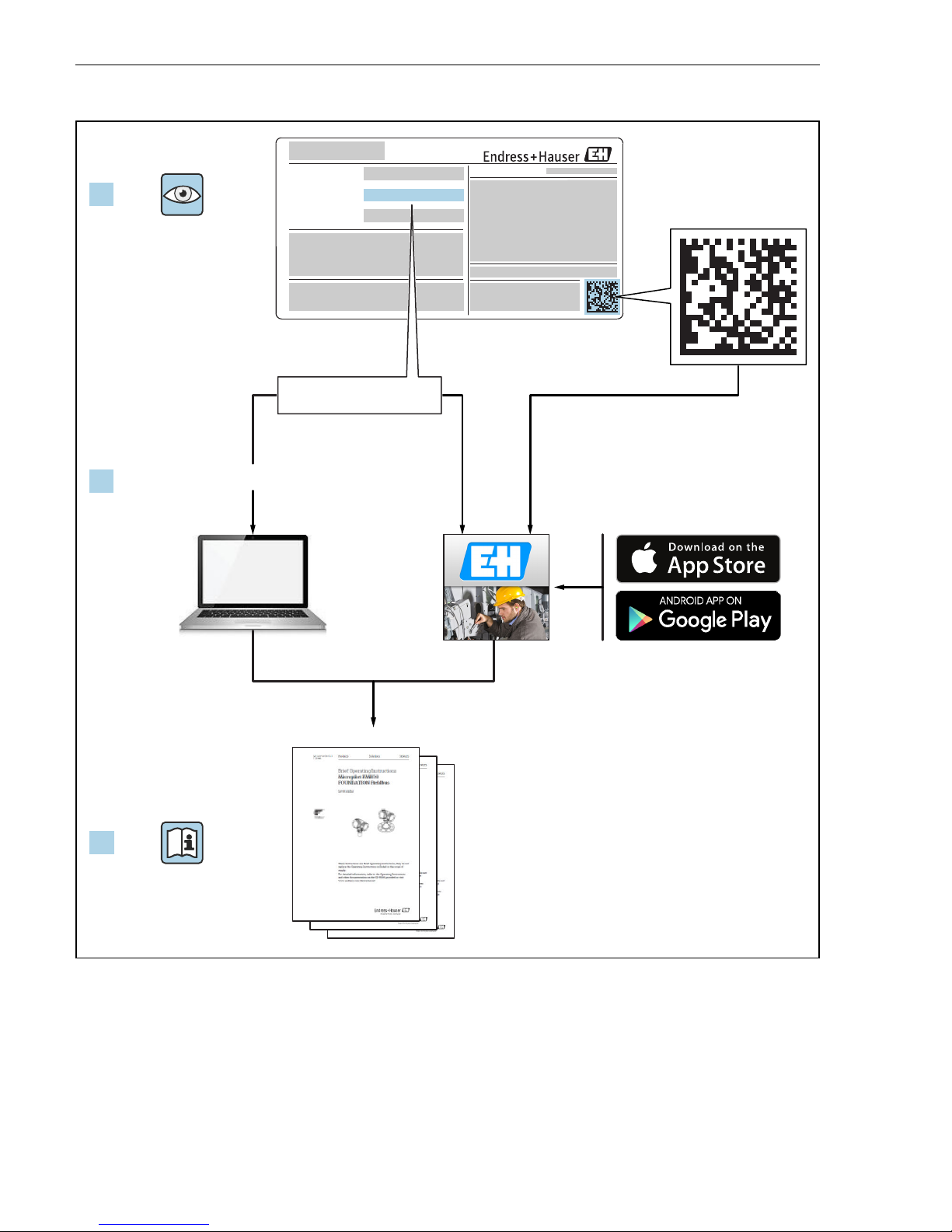
The "Transmitter Brief Operating Instructions" are available via:
• Internet: www.endress.com/deviceviewer
• Smart phone/tablet: Endress+Hauser Operations App
Detailed information about the device can be found in the Operating Instructions and the
other documentation:
• Internet: www.endress.com/deviceviewer
• Smart phone/tablet: Endress+Hauser Operations App
Page 4

Table of contents Proline Promass
4 Endress+Hauser
Table of contents
1 Document information ............................................................ 5
1.1 Symbols used ......................................................................... 5
2 Basic safety instructions .......................................................... 7
2.1 Requirements for the personnel ............................................................7
2.2 Designated use ........................................................................ 7
2.3 Workplace safety ...................................................................... 8
2.4 Operational safety ......................................................................8
2.5 Product safety .........................................................................8
2.6 IT security ............................................................................9
3 Incoming acceptance and product identification ...................................9
3.1 Incoming acceptance .................................................................... 9
3.2 Product identification .................................................................. 10
4 Storage and transport ........................................................... 11
4.1 Storage conditions .................................................................... 11
4.2 Transporting the product ................................................................11
5 Installation ...................................................................... 13
5.1 Installation conditions ..................................................................13
5.2 Mounting the measuring device ...........................................................29
5.3 Post-installation check ................................................................. 31
6 Disposal ......................................................................... 31
6.1 Removing the measuring device .......................................................... 31
6.2 Disposing of the measuring device ......................................................... 31
Page 5
Proline Promass Document information
Endress+Hauser 5
1 Document information
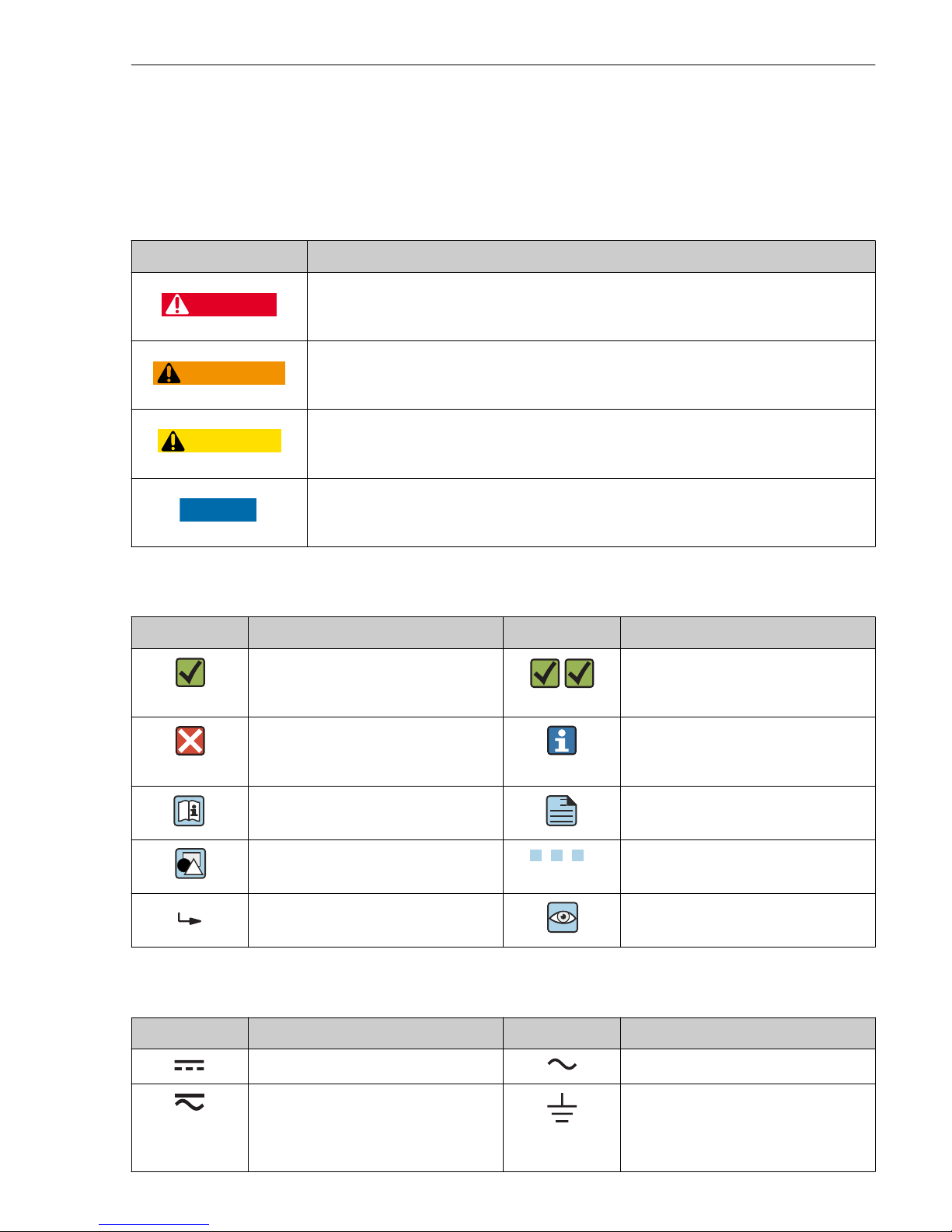
1.1 Symbols used
1.1.1 Safety symbols
Symbol Meaning
DANGER
DANGER!
This symbol alerts you to a dangerous situation. Failure to avoid this situation will result in
serious or fatal injury.
WARNING
WARNING!
This symbol alerts you to a dangerous situation. Failure to avoid this situation can result in
serious or fatal injury.
CAUTION
CAUTION!
This symbol alerts you to a dangerous situation. Failure to avoid this situation can result in
minor or medium injury.
NOTICE
NOTE!
This symbol contains information on procedures and other facts which do not result in
personal injury.
1.1.2 Symbols for certain types of information
Symbol Meaning Symbol Meaning
Permitted
Procedures, processes or actions that
are permitted.
Preferred
Procedures, processes or actions that
are preferred.
Forbidden
Procedures, processes or actions that
are forbidden.
Tip
Indicates additional information.
Reference to documentation
A
Reference to page
Reference to graphic
1.
, 2., 3.… Series of steps
Result of a step Visual inspection
1.1.3 Electrical symbols
Symbol Meaning Symbol Meaning
Direct current Alternating current
Direct current and alternating current Ground connection
A grounded terminal which, as far as
the operator is concerned, is grounded
via a grounding system.
Page 6
Document information Proline Promass
6 Endress+Hauser
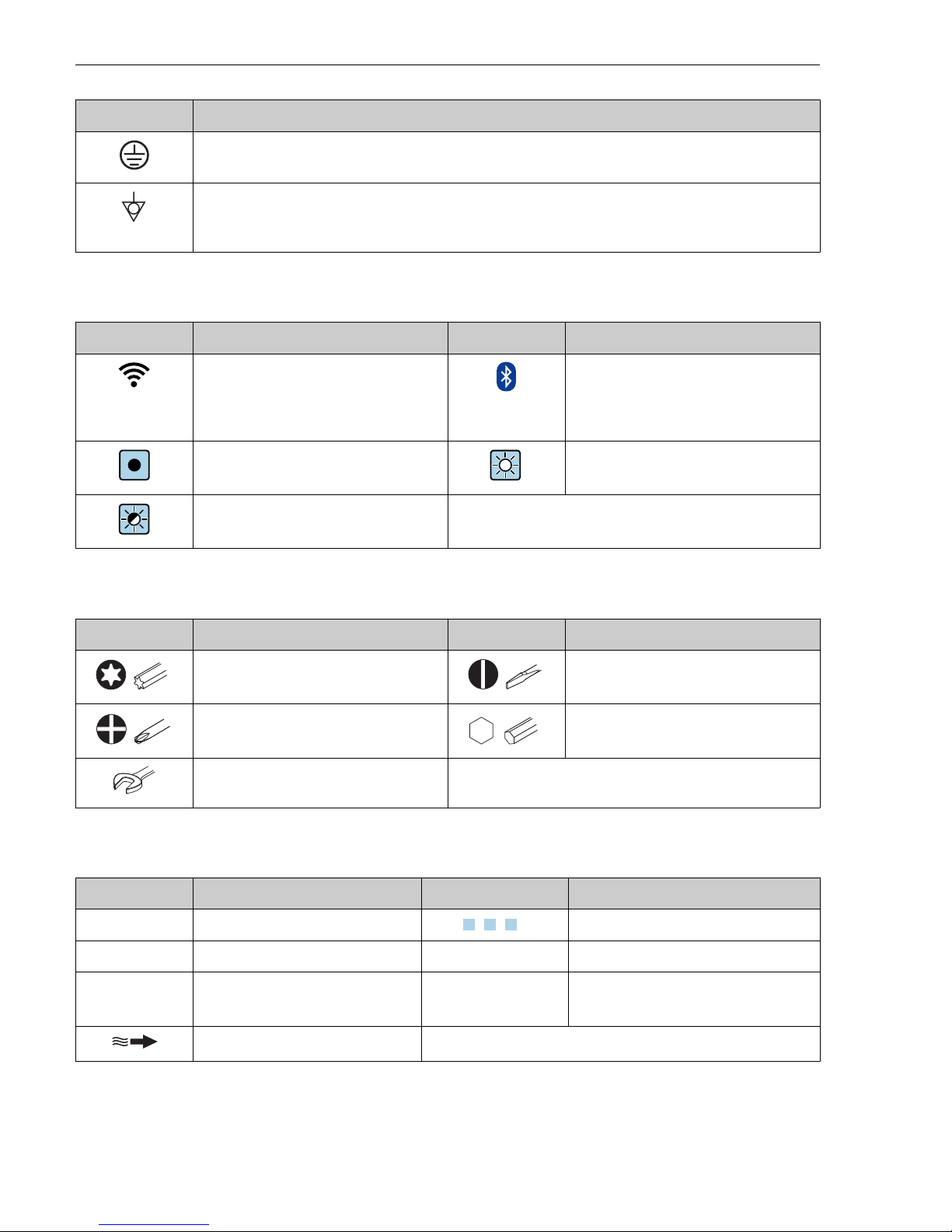
Symbol Meaning
Protective ground connection
A terminal which must be connected to ground prior to establishing any other connections.
Equipotential connection
A connection that has to be connected to the plant grounding system: This may be a potential
equalization line or a star grounding system depending on national or company codes of practice.
1.1.4 Communication symbols
Symbol Meaning Symbol Meaning
Wireless Local Area Network
(WLAN)
Communication via a wireless, local
network.
Bluetooth
Wireless data transmission between
devices over a short distance.
LED
Light emitting diode is off.
LED
Light emitting diode is on.
LED
Light emitting diode is flashing.
1.1.5 Tool symbols
Symbol Meaning Symbol Meaning
Torx screwdriver Flat blade screwdriver
Cross-head screwdriver Allen key
Open-ended wrench
1.1.6 Symbols in graphics
Symbol Meaning Symbol Meaning
1, 2, 3,... Item numbers
1.
, 2., 3.… Series of steps
A, B, C, ... Views A-A, B-B, C-C, ... Sections
-
Hazardous area
.
Safe area (non-hazardous area)
Flow direction
Page 7

Proline Promass Basic safety instructions
Endress+Hauser 7
2 Basic safety instructions
2.1 Requirements for the personnel
The personnel must fulfill the following requirements for its tasks:
‣
Trained, qualified specialists must have a relevant qualification for this specific function
and task.
‣
Are authorized by the plant owner/operator.
‣
Are familiar with federal/national regulations.
‣
Before starting work, read and understand the instructions in the manual and
supplementary documentation as well as the certificates (depending on the application).
‣
Follow instructions and comply with basic conditions.
2.2 Designated use
Application and media
The measuring device described in these Instructions is intended only for flow measurement
of liquids and gases.
Depending on the version ordered, the measuring device can also measure potentially
explosive, flammable, poisonous and oxidizing media.
Measuring devices for use in hazardous areas, in hygienic applications or where there is an
increased risk due to process pressure, are labeled accordingly on the nameplate.
To ensure that the measuring device remains in proper condition for the operation time:
‣
Only use the measuring device in full compliance with the data on the nameplate and the
general conditions listed in the Operating Instructions and supplementary documentation.
‣
Based on the nameplate, check whether the ordered device is permitted for the intended
use in the hazardous area (e.g. explosion protection, pressure vessel safety).
‣
Use the measuring device only for media to which the process-wetted materials are
sufficiently resistant.
‣
If the measuring device is not operated at atmospheric temperature, compliance with the
relevant basic conditions specified in the associated device documentation is absolutely
essential: "Documentation" section..
‣
Protect the measuring device permanently against corrosion from environmental
influences.
Incorrect use
Non-designated use can compromise safety. The manufacturer is not liable for damage caused
by improper or non-designated use.
L
WARNING
Danger of breakage due to corrosive or abrasive fluids!
‣
Verify the compatibility of the process fluid with the sensor material.
‣
Ensure the resistance of all fluid-wetted materials in the process.
‣
Keep within the specified pressure and temperature range.
Page 8

Basic safety instructions Proline Promass
8 Endress+Hauser
NOTICE
Verification for borderline cases:
‣
For special fluids and fluids for cleaning, Endress+Hauser is glad to provide assistance in
verifying the corrosion resistance of fluid-wetted materials, but does not accept any
warranty or liability as minute changes in the temperature, concentration or level of
contamination in the process can alter the corrosion resistance properties.
Residual risks
L
WARNING
The electronics and the medium may cause the surfaces to heat up. This presents a burn
hazard!
‣
For elevated fluid temperatures, ensure protection against contact to prevent burns.
L
WARNING
Danger of housing breaking due to measuring tube breakage!
‣
In the event of a measuring tube breakage for a device version without rupture disk it is
possible for the pressure loading capacity of the sensor housing to be exceeded. This can
lead to rupture or failure of the sensor housing.
2.3 Workplace safety
For work on and with the device:
‣
Wear the required personal protective equipment according to federal/national
regulations.
For welding work on the piping:
‣
Do not ground the welding unit via the measuring device.
If working on and with the device with wet hands:
‣
Due to the increased risk of electric shock, gloves must be worn.
2.4 Operational safety
Risk of injury!
‣
Operate the device in proper technical condition and fail-safe condition only.
‣
The operator is responsible for interference-free operation of the device.
2.5 Product safety
This measuring device is designed in accordance with good engineering practice to meet stateof-the-art safety requirements, has been tested, and left the factory in a condition in which it
is safe to operate.
It meets general safety standards and legal requirements. It also complies with the EU
directives listed in the device-specific EU Declaration of Conformity. Endress+Hauser confirms
this by affixing the CE mark to the device.
Page 9
Proline Promass Incoming acceptance and product identification
Endress+Hauser 9
2.6 IT security
We only provide a warranty if the device is installed and used as described in the Operating
Instructions. The device is equipped with security mechanisms to protect it against any
inadvertent changes to the device settings.
IT security measures in line with operators' security standards and designed to provide
additional protection for the device and device data transfer must be implemented by the
operators themselves.
3 Incoming acceptance and product identification
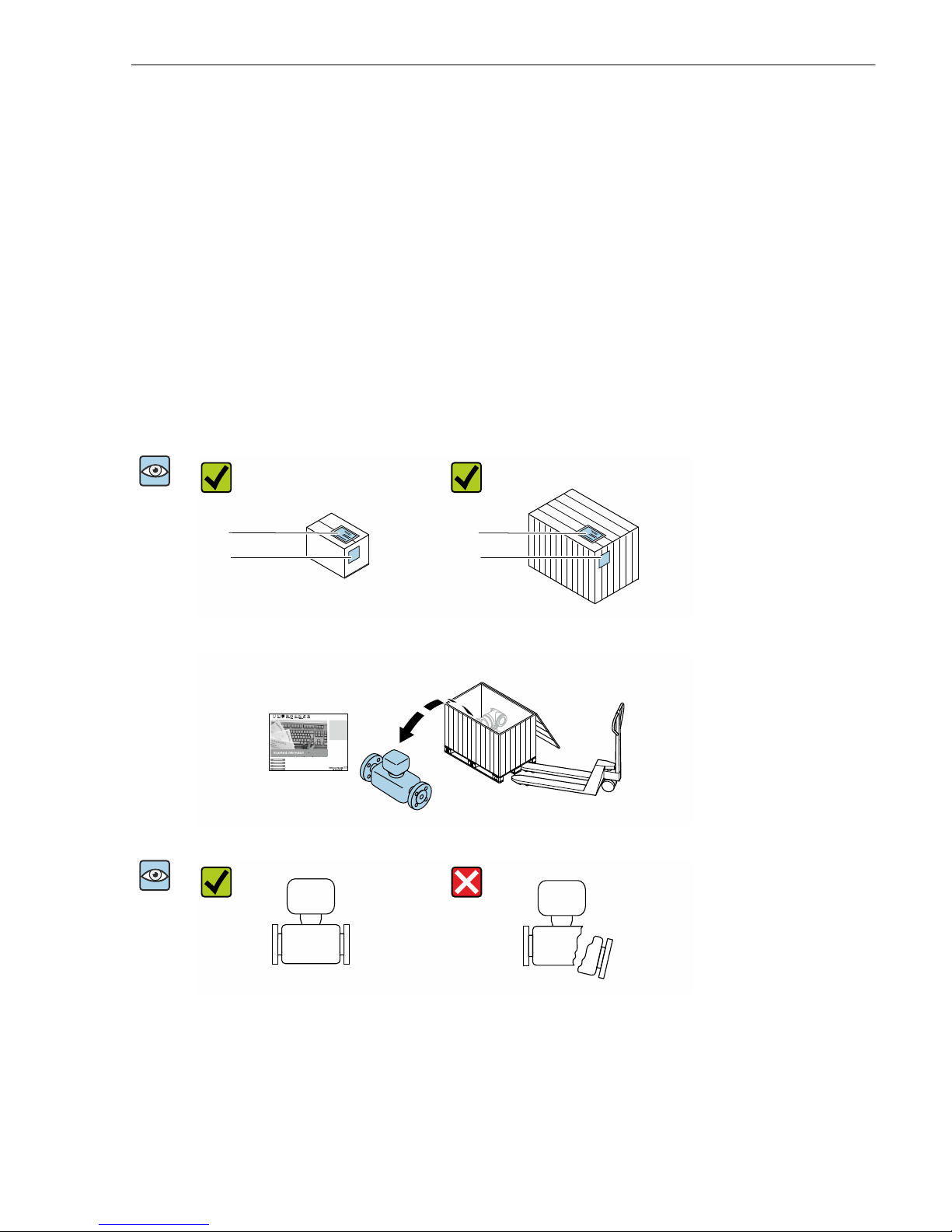
3.1 Incoming acceptance
A0028673
1
2
1
2
A0029314
Are the order codes on
the delivery note (1)
and the product sticker
(2) identical?
A0029315
A0028673
A0029316
Are the goods
undamaged?
Page 10
Incoming acceptance and product identification Proline Promass
10 Endress+Hauser
A0028673
Order code:
Ser. no.:
Ext. ord. cd.:
i
i
Date:
A0029317
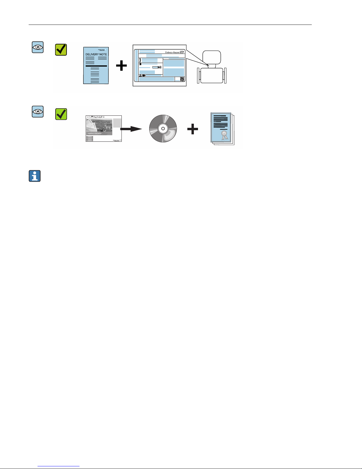
Do the nameplate data
match the ordering
information on the
delivery note?
A0028673
A0029318
Is the CD-ROM with the
Technical
Documentation
(depends on device
version) and documents
present?
• If one of the conditions is not satisfied, contact your Endress+Hauser Sales Center.
• Depending on the device version, the CD-ROM might not be part of the delivery! The
Technical Documentation is available via the Internet or via the Endress+Hauser
Operations App.
3.2 Product identification
The following options are available for identification of the measuring device:
• Nameplate specifications
• Order code with breakdown of the device features on the delivery note
• Enter serial numbers from nameplates in W@M Device Viewer
(www.endress.com/deviceviewer): All information about the measuring device is displayed.
• Enter the serial number from the nameplates into the Endress+Hauser Operations App or
scan the 2-D matrix code (QR code) on the nameplate with the Endress+Hauser Operations
App: all the information for the measuring device is displayed.
Page 11
Proline Promass Storage and transport
Endress+Hauser 11
Order code:
Ext. ord. cd.:
Ser. no.:
Order code:
Ext. ord. cd.:
Ser. no.:
1
2
3
4
A0030196
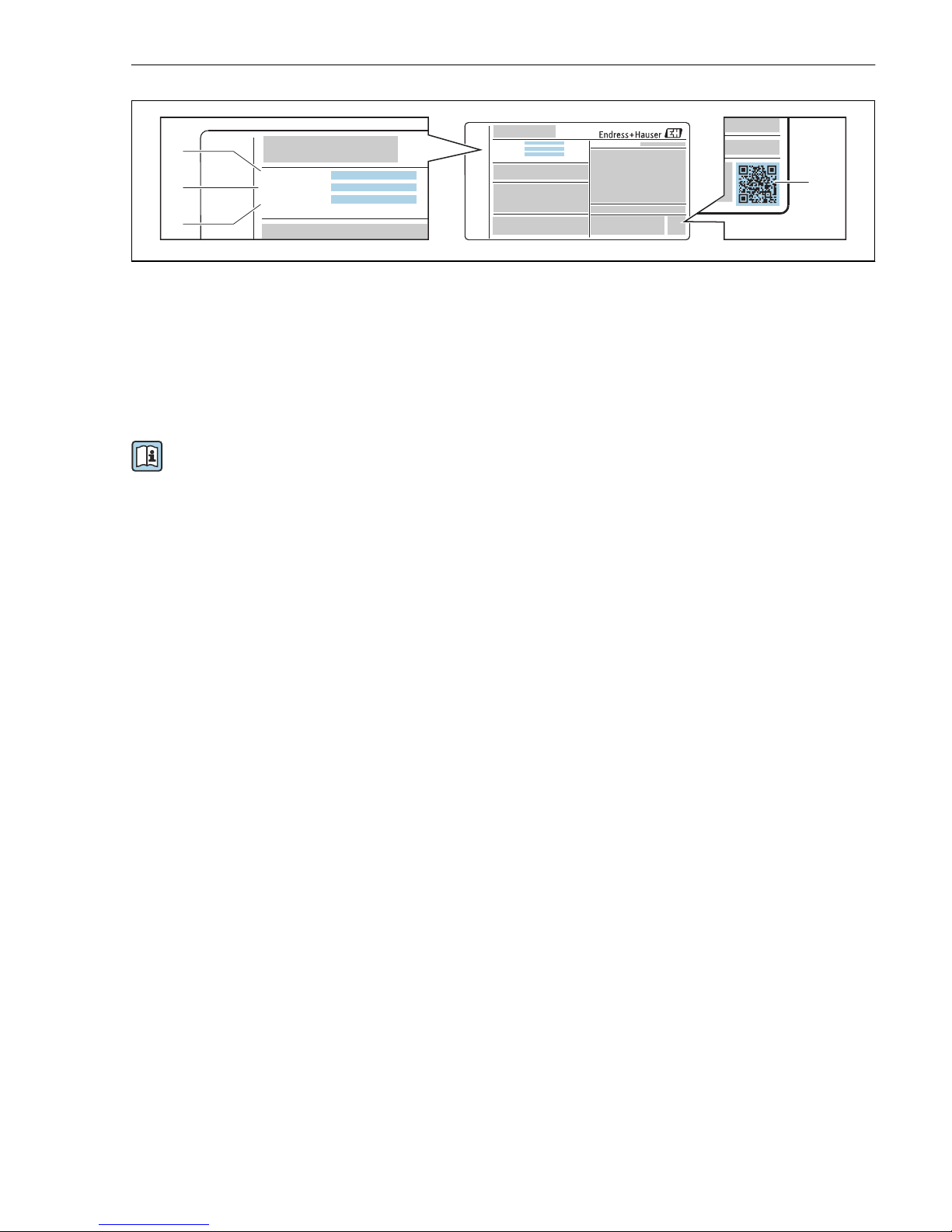
1 Example of a nameplate
1 Order code
2 Serial number (Ser. no.)
3 Extended order code (Ext. ord. cd.)
4 2-D matrix code (QR code)
For detailed information on the breakdown of the specifications on the nameplate, see
the Operating Instructions for the device .
4 Storage and transport
4.1 Storage conditions
Observe the following notes for storage:
‣
Store in the original packaging to ensure protection from shock.
‣
Do not remove protective covers or protective caps installed on process connections. They
prevent mechanical damage to the sealing surfaces and contamination in the measuring
tube.
‣
Protect from direct sunlight to avoid unacceptably high surface temperatures.
‣
Store in a dry and dust-free place.
‣
Do not store outdoors.
4.2 Transporting the product
Transport the measuring device to the measuring point in the original packaging.
Page 12
Storage and transport Proline Promass
12 Endress+Hauser
A0029252
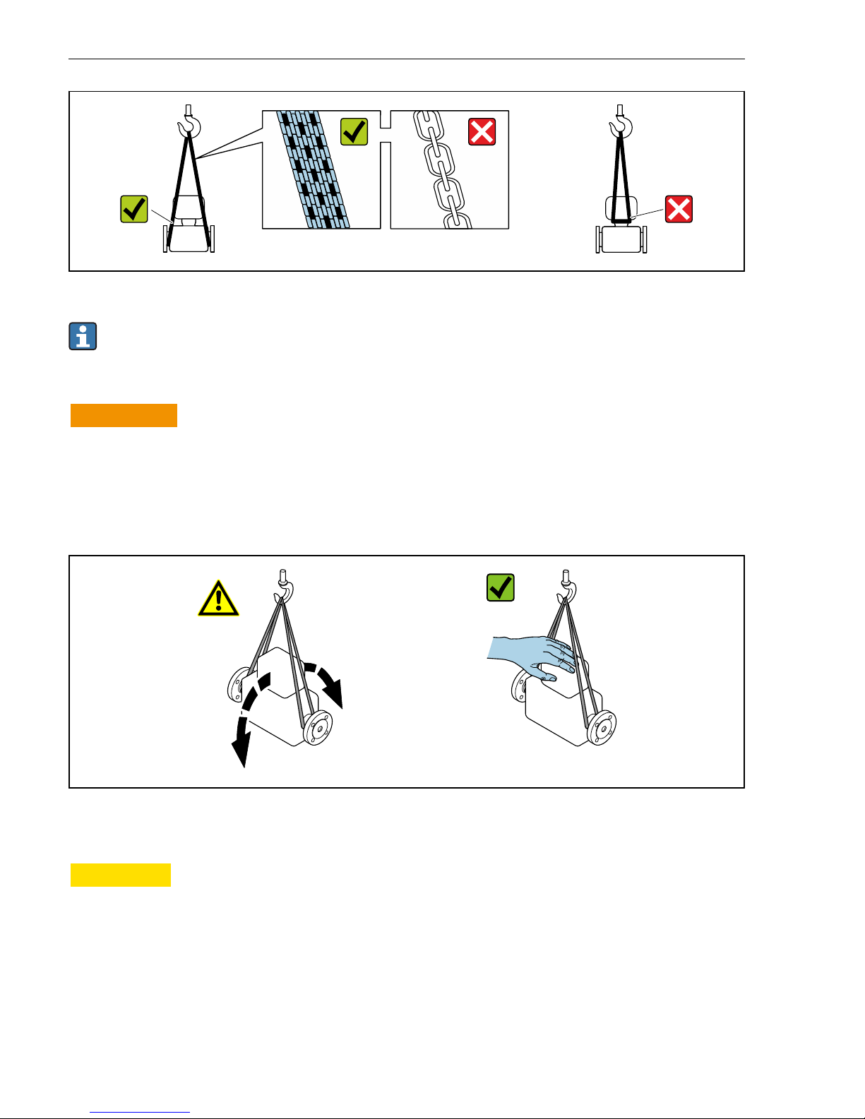
Do not remove protective covers or caps installed on process connections. They prevent
mechanical damage to the sealing surfaces and contamination in the measuring tube.
4.2.1 Measuring devices without lifting lugs
L
WARNING
Center of gravity of the measuring device is higher than the suspension points of the
webbing slings.
Risk of injury if the measuring device slips.
‣
Secure the measuring device against slipping or turning.
‣
Observe the weight specified on the packaging (stick-on label).
A0029214
4.2.2 Measuring devices with lifting lugs
L
CAUTION
Special transportation instructions for devices with lifting lugs
‣
Only use the lifting lugs fitted on the device or flanges to transport the device.
‣
The device must always be secured at two lifting lugs at least.
4.2.3 Transporting with a fork lift
If transporting in wood crates, the floor structure enables the crates to be lifted lengthwise or
at both sides using a forklift.
Page 13
Proline Promass Installation
Endress+Hauser 13
5 Installation
5.1 Installation conditions
No special measures such as supports are necessary. External forces are absorbed by the
construction of the device.
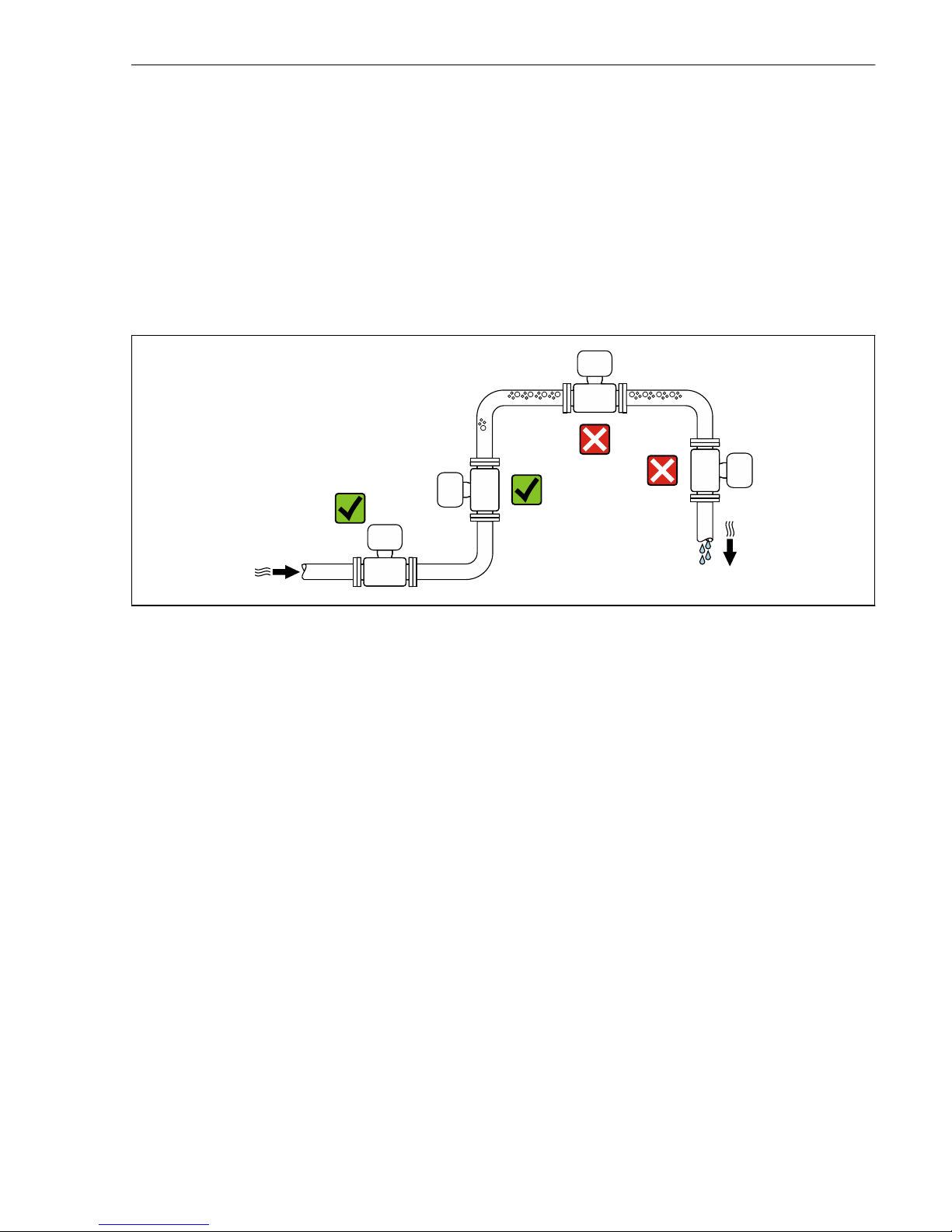
5.1.1 Mounting position
Mounting location
A0028772
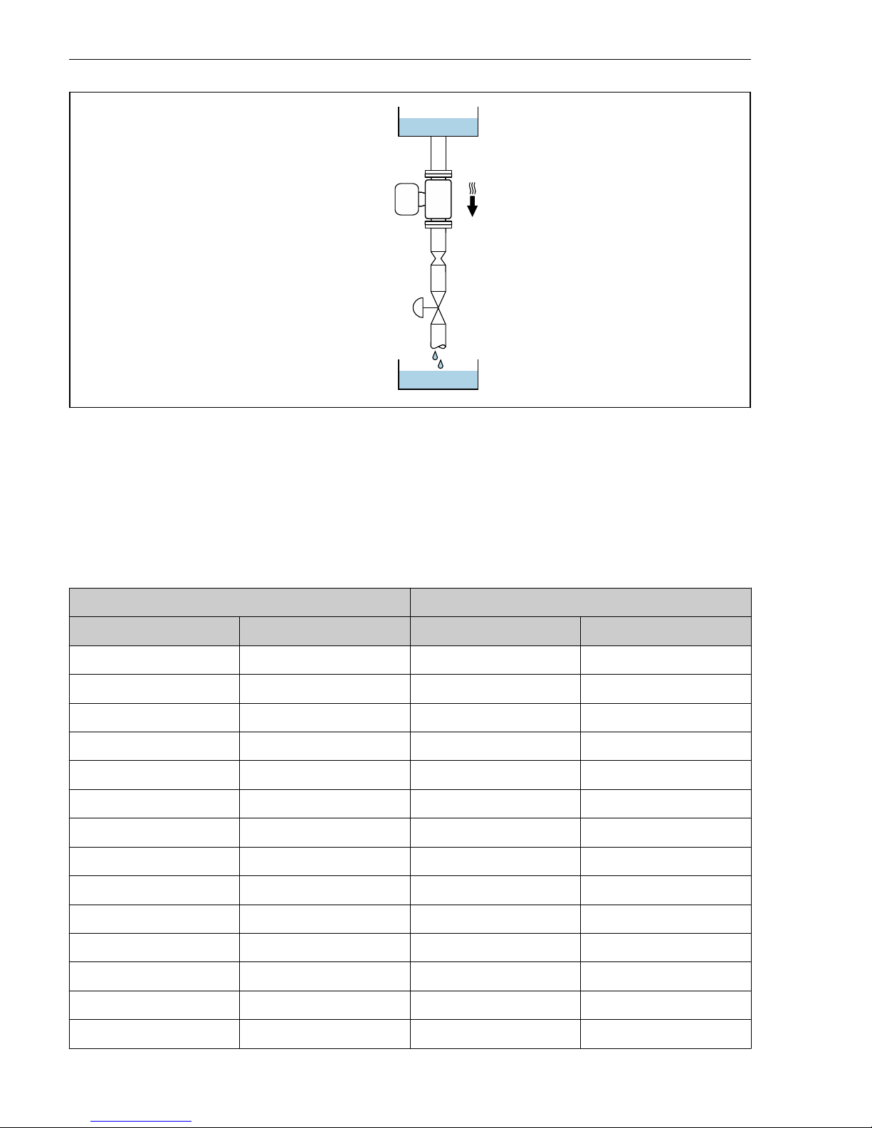
Installation in down pipes
However, the following installation suggestion allows for installation in an open vertical
pipeline. Pipe restrictions or the use of an orifice with a smaller cross-section than the
nominal diameter prevent the sensor running empty while measurement is in progress.
Page 14
Installation Proline Promass
14 Endress+Hauser
1
2
3
4
5
A0028773
2 Installation in a down pipe (e.g. for batching applications)
1 Supply tank
2 Sensor
3 Orifice plate, pipe restriction
4 Valve
5 Batching tank
DN Ø orifice plate, pipe restriction
[mm] [in] [mm] [in]
1 ¹⁄₂₄ 0,8 0,03
2 ¹⁄₁₂ 1,5 0,06
4 ¹⁄₈ 3,0 0,12
8 ³⁄₈ 6 0,24
15 ½ 10 0,40
15 FB ½ FB 15 0,60
25 1 14 0,55
25 FB 1 FB 24 0,95
40 1½ 22 0,87
40 FB 1½ FB 35 1,38
50 2 28 1,10
50 FB 2 FB 54 2,13
80 3 50 1,97
100 4 65 2,60
Page 15
Proline Promass Installation
Endress+Hauser 15
DN Ø orifice plate, pipe restriction
[mm] [in] [mm] [in]
150 6 90 3,54
250 10 150 5,91
300 12 210 8,27
350 14 210 8,27
400 16 210 8,27
FB = Full bore
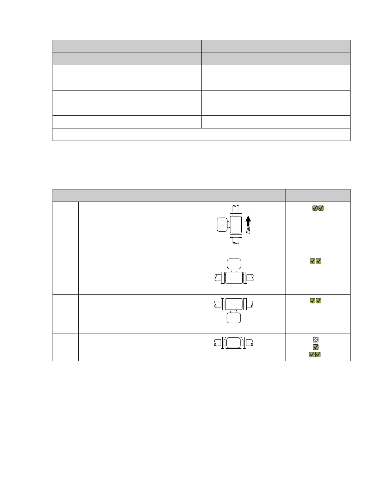
Orientation
The direction of the arrow on the sensor nameplate helps you to install the sensor according
to the flow direction.
Orientation Recommendation
A Vertical orientation
A0015591
B Horizontal orientation, transmitter at
top
A0015589
1)
Exceptions:
→ 3, 16
C Horizontal orientation, transmitter at
bottom
A0015590
2)
Exceptions:
→ 3, 16
D Horizontal orientation, transmitter at
side
A0015592
3)
4)
5)
1) Applications with low process temperatures may decrease the ambient temperature. To maintain the minimum
ambient temperature for the transmitter, this orientation is recommended.
2) Applications with high process temperatures may increase the ambient temperature. To maintain the maximum
ambient temperature for the transmitter, this orientation is recommended.
3) Promass A, E, F, G, O
4) Promass X
5) Promass H, I, P, Q, S
Page 16
Installation Proline Promass
16 Endress+Hauser
1 2
A0028774
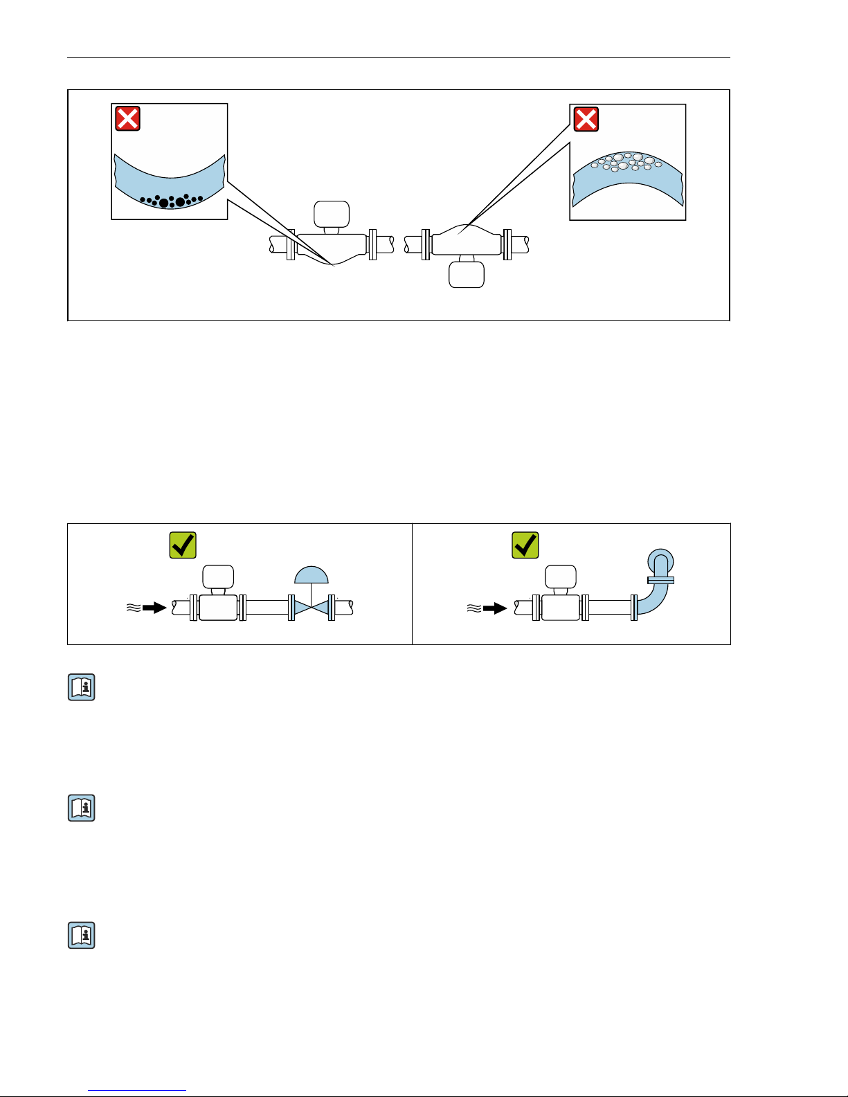
3 Orientation of sensor with curved measuring tube
1 Avoid this orientation for fluids with entrained solids: Risk of solids accumulating.
2 Avoid this orientation for outgassing fluids: Risk of gas accumulating.
Inlet and outlet runs
No special precautions need to be taken for fittings which create turbulence, such as valves,
elbows or T-pieces, as long as no cavitation occurs → 17.
A0029322 A0029323
For the dimensions and installation lengths of the device, see the "Technical Information"
document, "Mechanical construction" section
5.1.2 Requirements from environment and process
Ambient temperature range
For detailed information on the ambient temperature range, see the Operating
Instructions for the device.
If operating outdoors:
Avoid direct sunlight, particularly in warm climatic regions.
Temperature tables
For detailed information on the temperature tables, see the separate document entitled
"Safety Instructions" (XA) for the device.
Page 17
Proline Promass Installation
Endress+Hauser 17
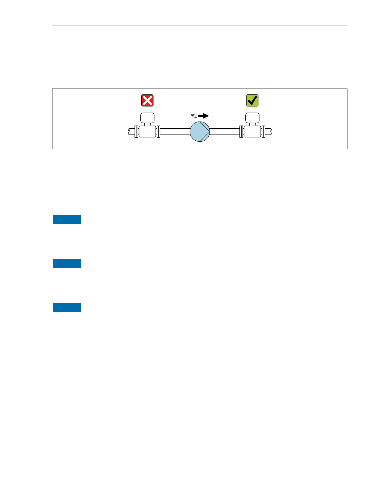
System pressure
For this reason, the following mounting locations are recommended:
• At the lowest point in a vertical pipe
• Downstream from pumps (no danger of vacuum)
A0028777
Thermal insulation
In the case of some fluids, it is important that the heat radiated from the sensor to the
transmitter is kept to a minimum. A wide range of materials can be used for the required
insulation.
NOTICE
Electronics overheating on account of thermal insulation!
‣
Observe maximum permitted insulation height of the transmitter neck so that the
transmitter head is completely free.
NOTICE
Danger of overheating with insulation
‣
Ensure that the temperature at the lower end of the transmitter housing sensor housing
does not exceed 80 °C (176 °F)
NOTICE
The insulation can also be thicker than the maximum recommended insulation
thickness.
Prerequisite:
‣
Ensure that convection takes place on a sufficiently large scale at the transmitter neck.
‣
Ensure that a sufficiently large area of the housing support remains exposed. The
uncovered part serves as a radiator and protects the electronics from overheating and
excessive cooling.
Page 18
Installation Proline Promass
18 Endress+Hauser
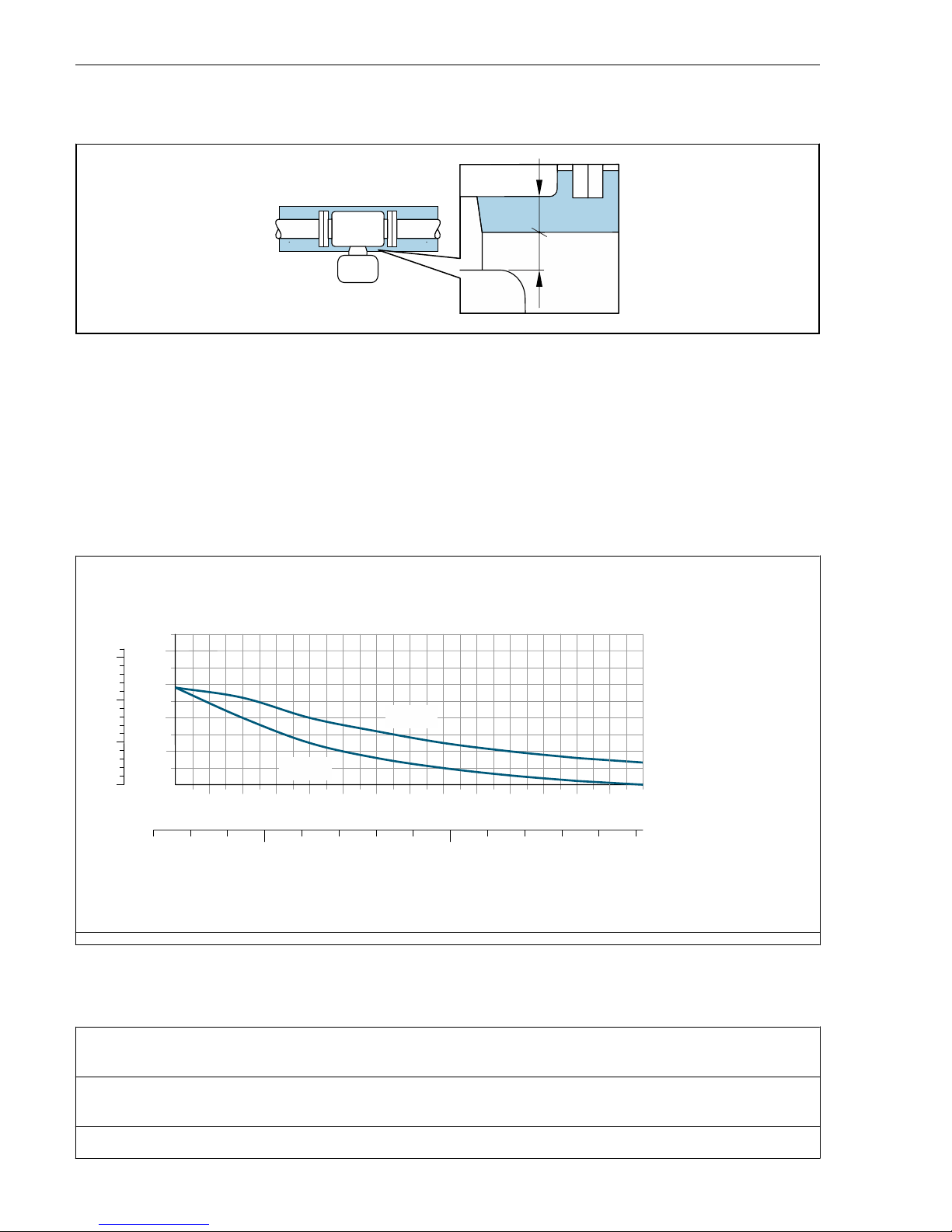
Promass 100, 300, 500
t
a
A0028853
a Minimum distance to insulation
t maximum Insulation thickness
The minimum distance a between the transmitter sensor connection housing and the
insulation is 10 mm (0,39 in) 20 mm (0,79 in). This is to ensure that the transmitter sensor
connection housing remains completely exposed.
Maximum recommended insulation thickness
Valid for Promass E, F, I, P, S
0
10
30
20
40
[ ]mm[ ]in
80 90 100 110
[°C]
[°F]
200 250 290
0.5
1.0
1.5
0
t
40(104)
t
60(140)
t
120 130 140
T
m
150
A0028904
4 Maximum recommended insulation thickness depending on the temperature of the medium and
the ambient temperature
Maximum recommended insulation thickness depending on the medium temperature and
ambient temperature for the extended temperature range or insulation
Promass F: For the extended temperature range, version with long extension neck, order code for "Measuring tube
material", option SD, SE, SF, TH or extension neck for insulation, order code for "Sensor option", option CG
Promass P: For the extended temperature range, version with long extension neck, order code for "Measuring tube
material", option TD, TG or extension neck for insulation, order code for "Sensor option", option CG
Promass I and S: For the version extension neck for insulation order code for "Sensor option", option CG
Page 19
Proline Promass Installation
Endress+Hauser 19
0
20
60
40
80
1
2
3
0
t
100
4
[ ]mm
t
40(104)
t
60(140)
80 100 120 140
200 300
160
[°F]
T
m
[°C]
A0029981
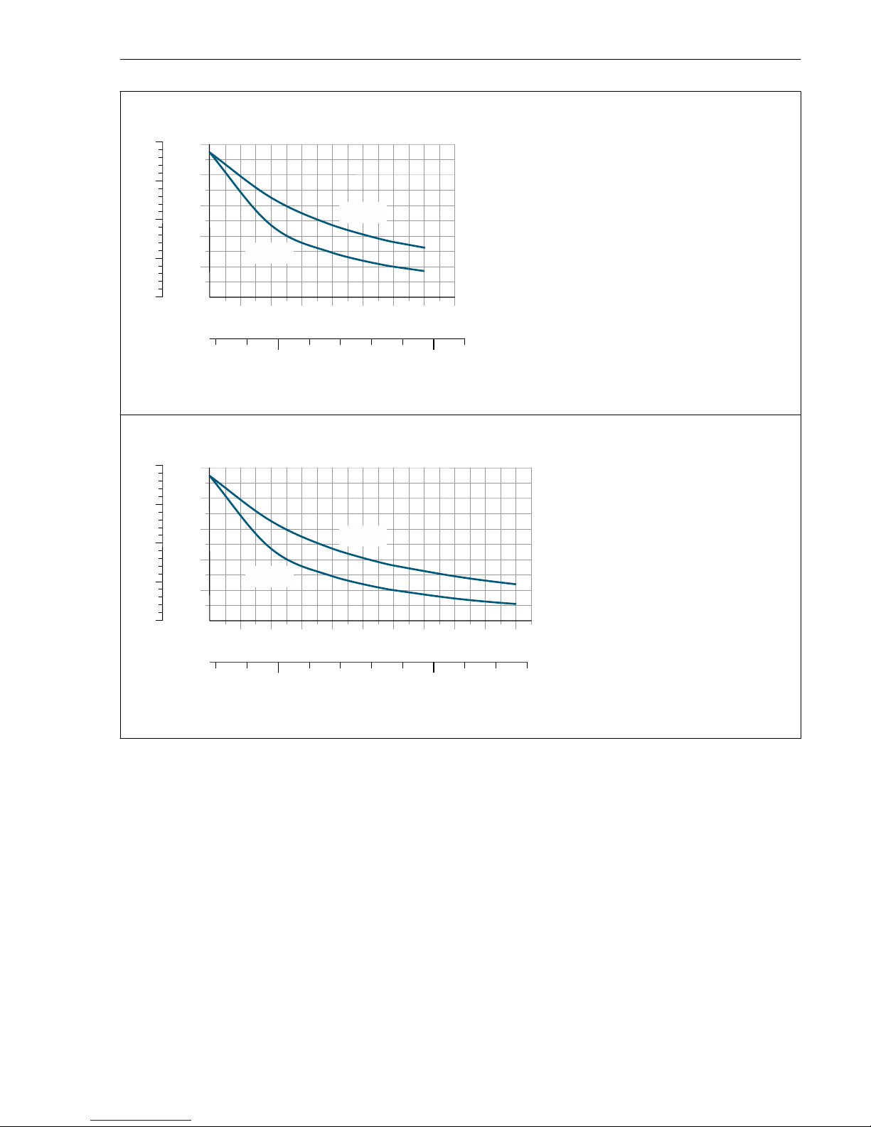
5 Valid for Promass I, S
0
20
60
40
80
1
2
3
0
t
100
4
[ ]mm
t
40(104)
t
60(140)
80 100 120 140
200 300
160 180
[°F]
T
m
[°C]
A0029990
6 Valid for Promass X
Page 20
Installation Proline Promass
20 Endress+Hauser
0
20
60
40
80
1
2
3
0
t
100
4
[ ]mm
t
40(104)
t
60(140)
80 100 120 140
200 300 400
160 180 200
[°F]
T
m
[°C]
A0029921
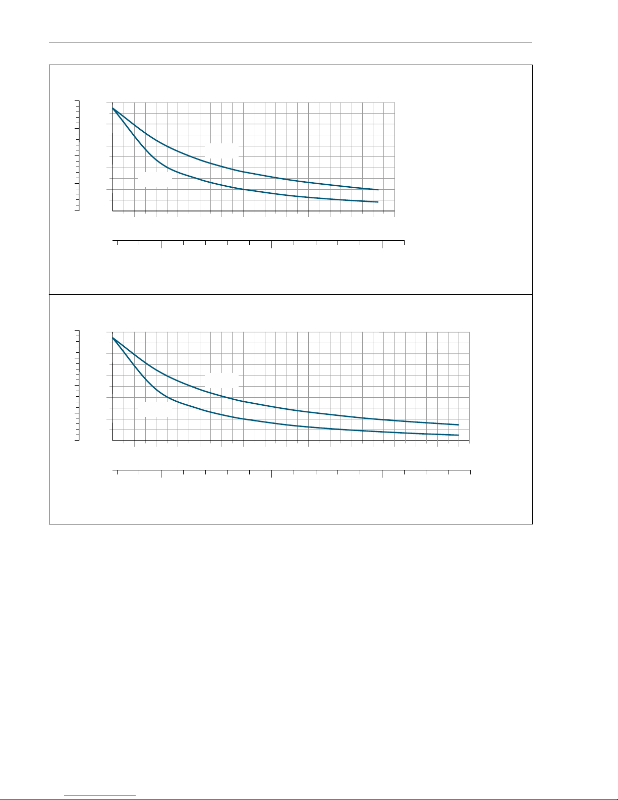
7 Valid for Promass A, H, O, P, Q
0
20
60
40
80
1
2
3
0
t
100
4
[ ]mm
t
40(104)
t
60(140)
80 100 120 140
200 300 400
160 180 200
[°F]
T
m
[°C]
220
240
A0028906
8 Valid for Promass F
t Insulation thickness
T
m
Medium temperature
T
40(104)
Maximum recommended insulation thickness at an ambient temperature of Ta = 40 °C (104 °F)
T
60(140)
Maximum recommended insulation thickness at an ambient temperature of Ta = 60 °C (140 °F)
Page 21
Proline Promass Installation
Endress+Hauser 21
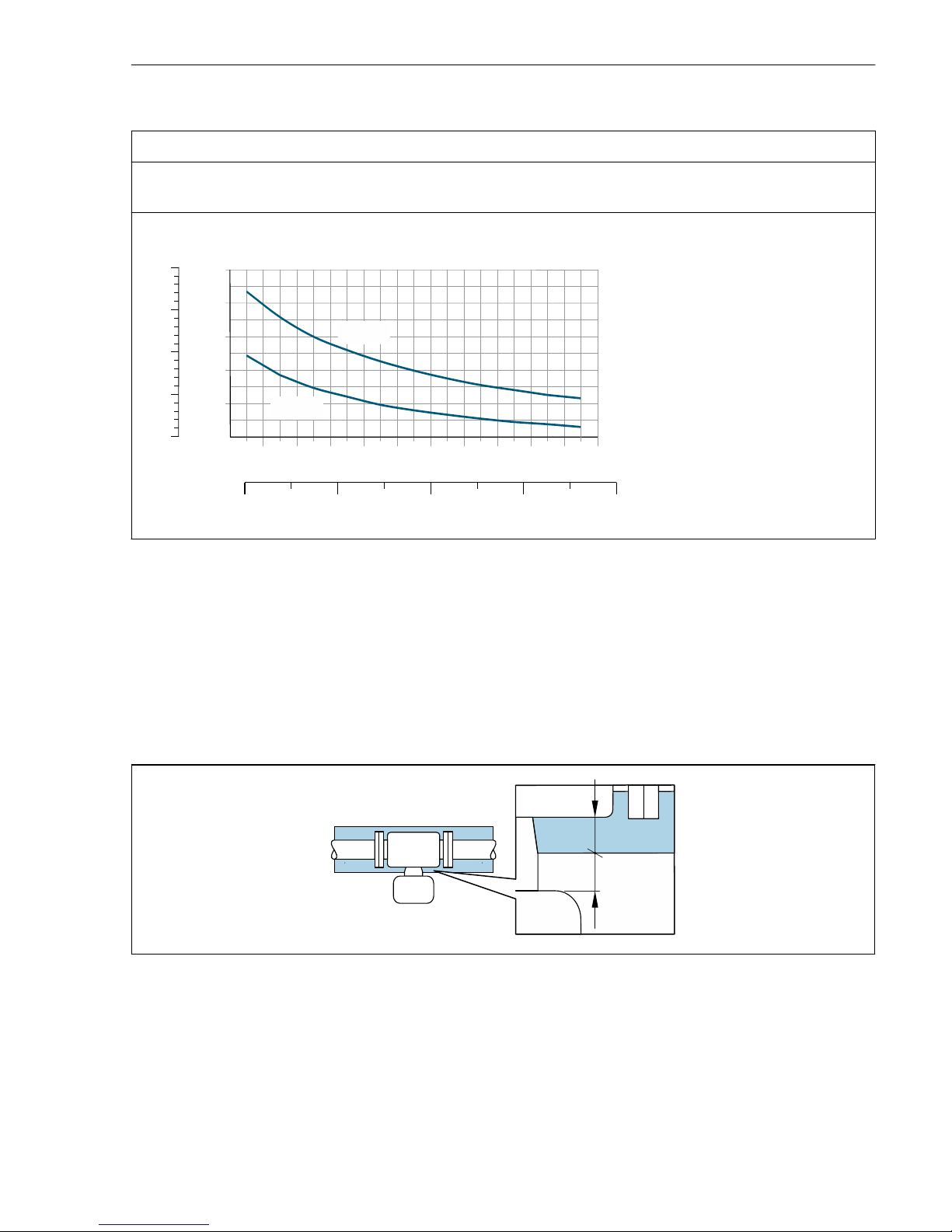
Maximum recommended insulation thickness for the high-temperature range
Only Promass F
For the extended temperature range, version with long extension neck, order code for "Measuring tube material",
option TT, TU:
0
10
30
20
40
0.5
1.0
1.5
0
t
50
2.0
[mm]
t
40(104)
t
60(140)
200
240
300
500 700
280
[°F]
T
m
[°C]
320
160
360
600400
A0029903
t Insulation thickness
T
m
Medium temperature
t40
(104)
Maximum recommended insulation thickness at an ambient temperature of Ta = 40 °C (104 °F)
t60
(140)
Maximum recommended insulation thickness at an ambient temperature of Ta = 60 °C (140 °F)
Promass 200
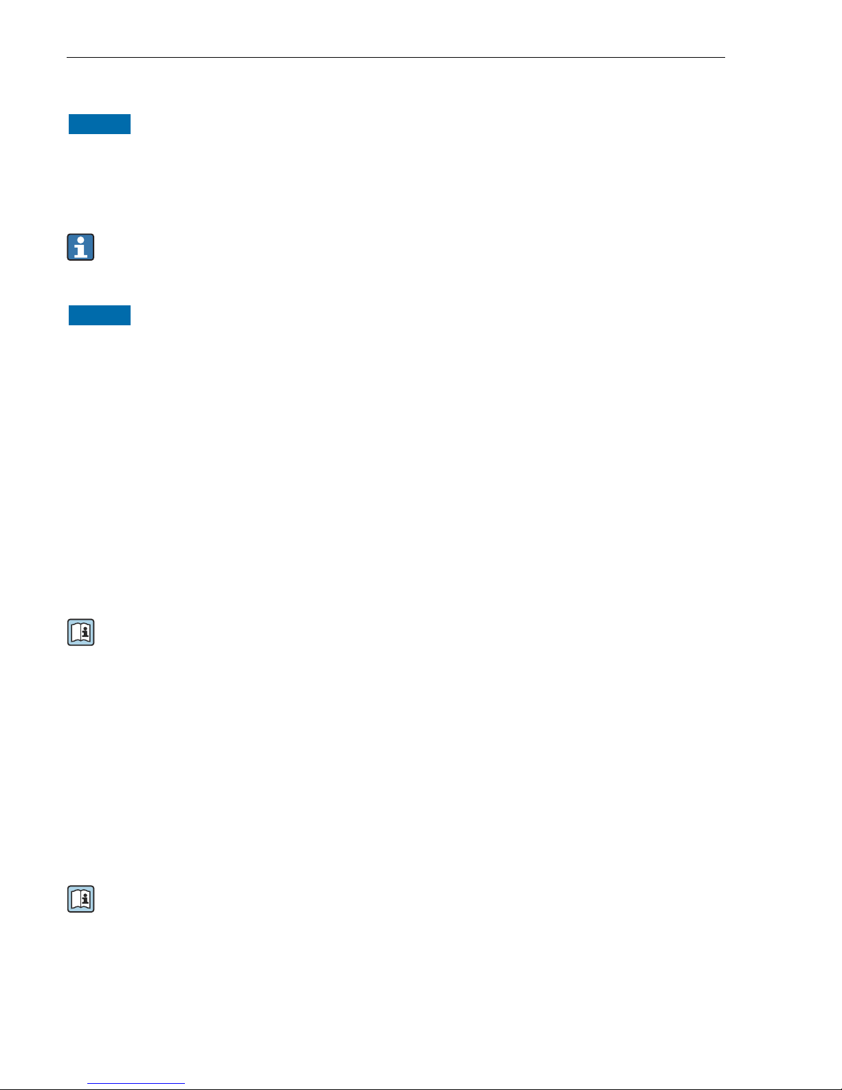
t
a
A0028853
a Minimum distance to insulation
t maximum Insulation thickness
The minimum distance a between the transmitter sensor connection housing and the
insulation is 10 mm (0,39 in) 20 mm (0,79 in). This is to ensure that the transmitter sensor
connection housing remains completely exposed.
Page 22
Installation Proline Promass
22 Endress+Hauser
Heating
NOTICE
Electronics can overheat due to elevated ambient temperature!
‣
Observe maximum permitted ambient temperature for the transmitter .
‣
Depending on the fluid temperature, take the device orientation requirements into
account .
Under critical climatic conditions, in particular, it is important to ensure that the
temperature difference between the ambient temperature and the fluid temperature is
not >100 K. Suitable measures must be taken, such as heating or insulation.
NOTICE
Danger of overheating when heating
‣
Ensure that the temperature at the lower end of the transmitter housing does not exceed
80 °C (176 °F).
‣
Ensure that convection takes place on a sufficiently large scale at the transmitter neck.
‣
Ensure that a sufficiently large area of the housing support remains exposed. The
uncovered part serves as a radiator and protects the electronics from overheating and
excessive cooling.
Heating options
If a fluid requires that no heat loss should occur at the sensor, users can avail of the following
heating options:
• Electrical heating, e.g. with electric band heaters
• Via pipes carrying hot water or steam
• Via heating jackets
For detailed information about heating with electrical band heaters, refer to the
Operating Instructions for the device on the CD-ROM provided
Vibrations
The high oscillation frequency of the measuring tubes ensures that the correct operation of
the measuring system is not influenced by plant vibrations.
The operational reliability of the measuring system is not affected by plant vibrations.
5.1.3 Special mounting instructions
Rupture disk
‣
After the rupture disk is actuated, do not operate the measuring device any more.
For detailed information about using a rupture disk, refer to the Operating Instructions
for the device on the CD-ROM provided
Promass A, F, O, Q
Make sure that the function and operation of the rupture disk is not impeded through the
installation of the device. The position of the rupture disk is indicated on a sticker beside it.
The transportation guard must be removed.
Page 23
Proline Promass Installation
Endress+Hauser 23
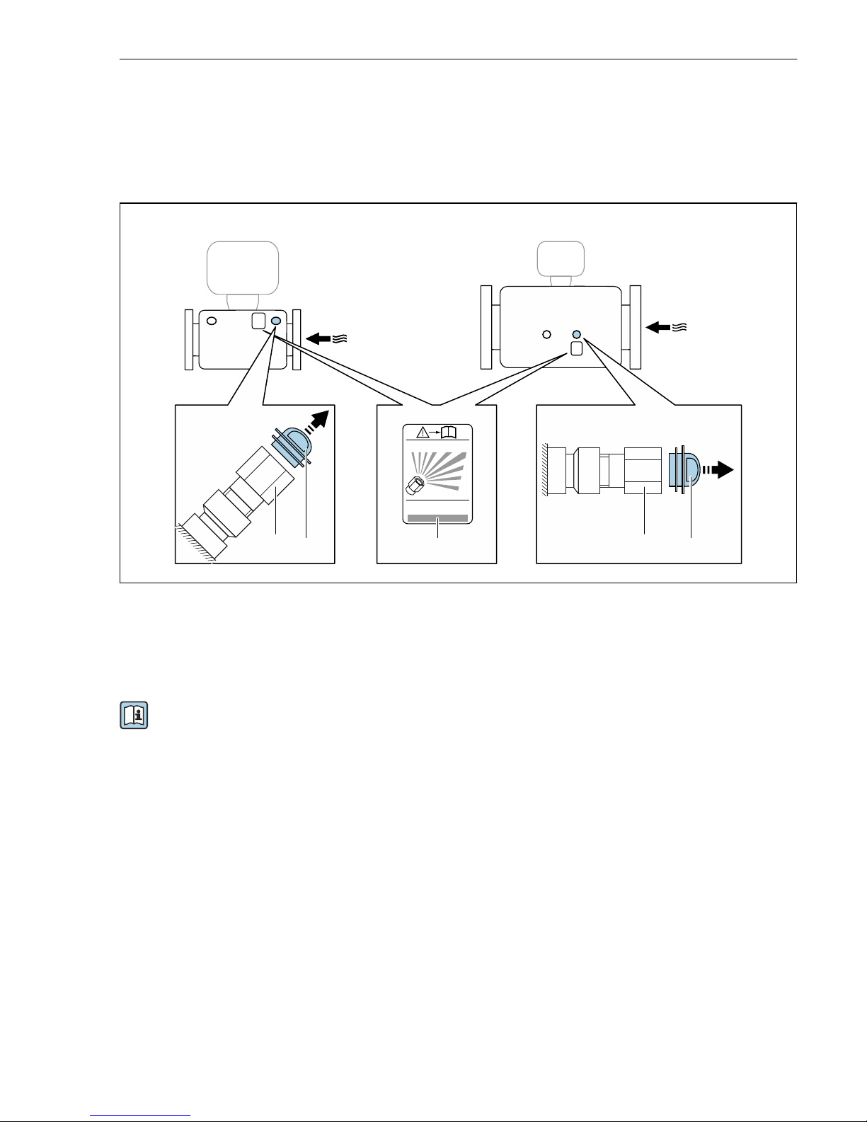
The existing connecting nozzles are not intended for the purpose of rinsing or pressure
monitoring, but instead serve as the mounting location for the rupture disk.
In the event of a failure of the rupture disk, a discharge device can be screwed onto the
internal thread of the rupture disk in order to drain off any escaping medium.
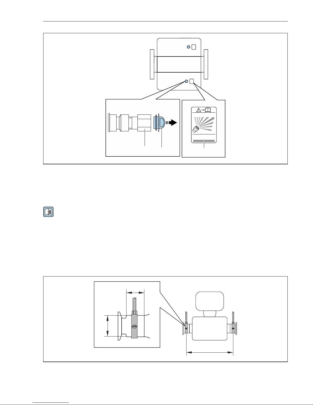
RUPTURE DISK
i
2
3
1
DN 8 ( ")...150 (6")!⁄# DN 250 (10")
2
3
A0028903
1 Rupture disk label
2 Rupture disk with 1/2" NPT internal thread with 1" width across flat
3 Transport protection
For information on the dimensions: see the "Mechanical construction" section of the
"Technical Information" document
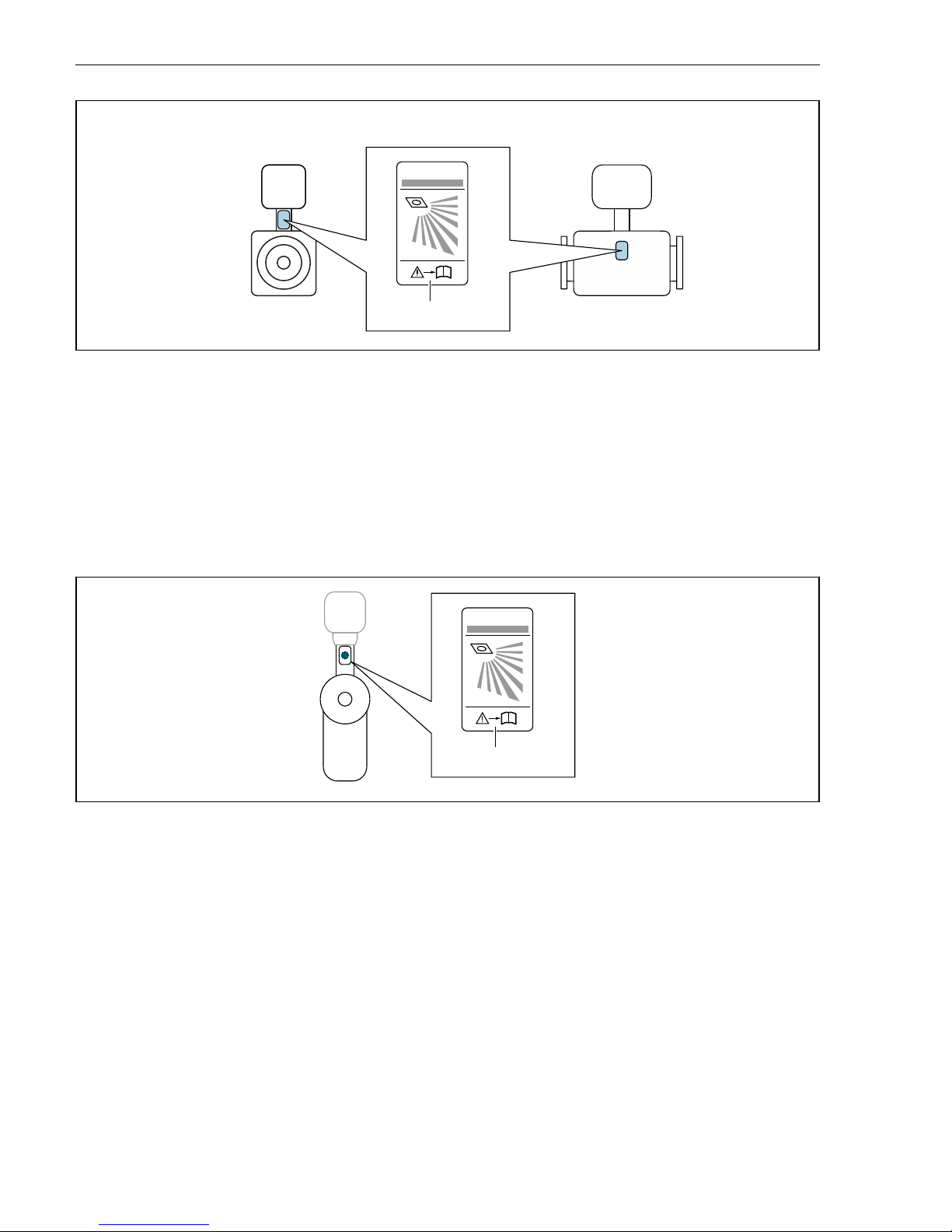
Promass E
Make sure that the function and operation of the rupture disk is not impeded through the
installation of the device. The position of the rupture disk is indicated on a sticker applied over
it. If the rupture disk is triggered, the sticker is destroyed. The disk can therefore be visually
monitored.
Page 24
Installation Proline Promass
24 Endress+Hauser
RUPTURE DISK
i
1
DN 8 ( ")... ( ")!⁄# 50 2 DN ( ")80 3
A0029956
9 Rupture disk label
PromassG
Make sure that the function and operation of the rupture disk is not impeded through the
installation of the device. The position of the rupture disk is indicated on a sticker applied over
it. If the rupture disk is triggered, the sticker is destroyed. The disk can therefore be visually
monitored.
RUPTURE DISK
i
1
A0030005
Promass X
Make sure that the function and operation of the rupture disk is not impeded through the
installation of the device. The position of the rupture disk is indicated on a sticker beside it.
The transportation guard must be removed.
The existing connecting nozzles are not intended for the purpose of rinsing or pressure
monitoring, but instead serve as the mounting location for the rupture disk.
In the event of a failure of the rupture disk, a discharge device can be screwed onto the
internal thread of the rupture disk in order to drain off any escaping medium.
Page 25
Proline Promass Installation
Endress+Hauser 25
RUPTURE DISK
i
2
3
1
A0029944
1 Rupture disk label
2 Rupture disk with 1/2" NPT internal thread with 1" width across flat
3 Transport protection
For information on the dimensions: see the "Mechanical construction" section of the
"Technical Information" document
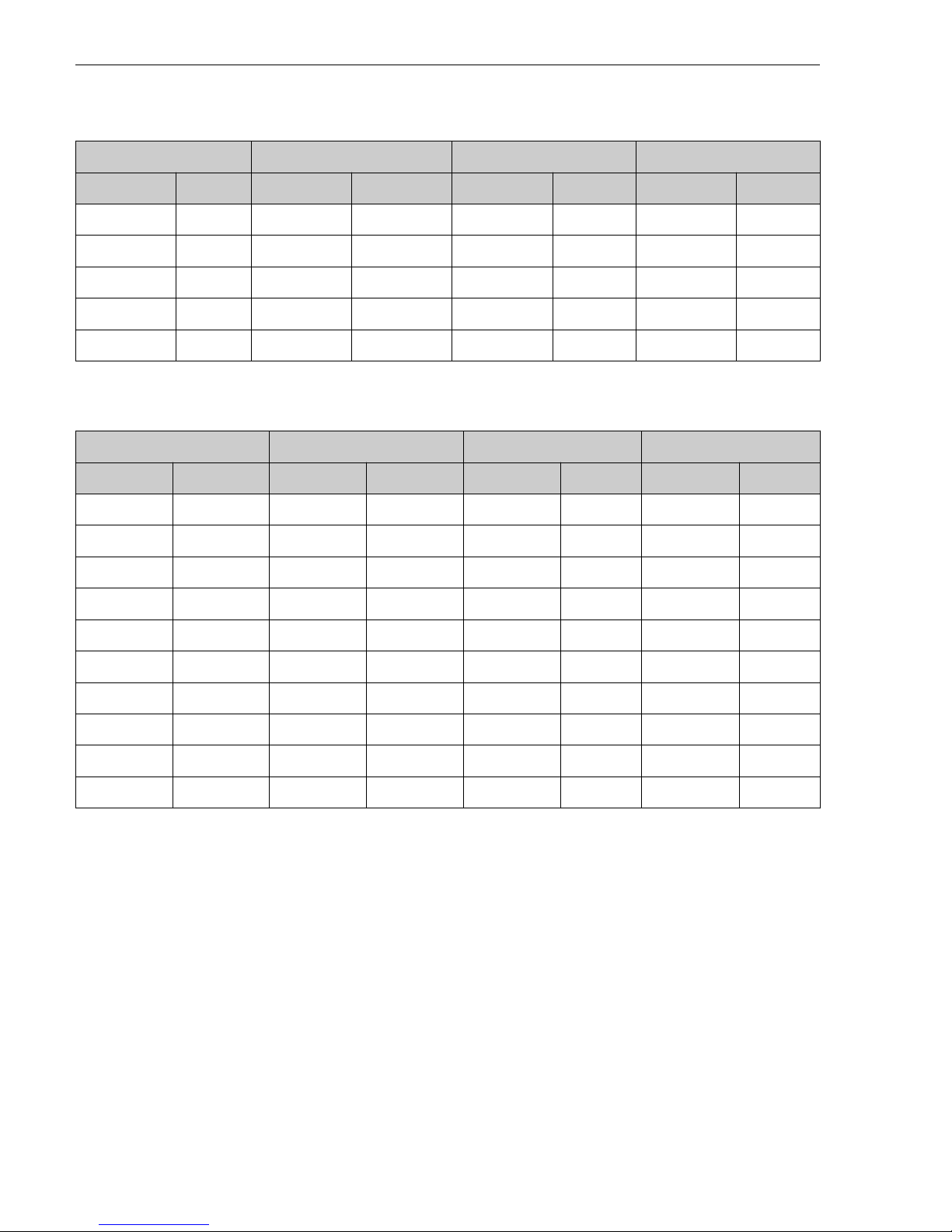
Securing with mounting clamps for hygiene connections(Promass I, P, S)
It is not necessary to provide additional support for the sensor for operational performance
purposes. If, however, additional support is required for installation purposes, the following
dimensions must be observed.
Use mounting clamp with lining between clamp and measuring instrument.
A
B
C
A0016588
Page 26
Installation Proline Promass
26 Endress+Hauser
Promass P, S
DN A B C
[mm] [in] [mm] [in] [mm] [in] [mm] [in]
8 ³⁄₈ 298 11,73 33 1,3 28 1,1
15 ½ 402 15,83 33 1,3 28 1,1
25 1 542 21,34 33 1,3 38 1,5
40 1 ½ 658 25,91 36,5 1,44 56 2,2
50 2 772 30,39 44,1 1,74 75 2,95
Promass I
DN A B C
[mm] [in] [mm] [in] [mm] [in] [mm] [in]
8 8 373 14,69 20 0,79 40 1,57
15 15 409 16,1 20 0,79 40 1,57
15 FB 15 FB 539 21,22 30 1,18 44,5 1,75
25 25 539 21,22 30 1,18 44,5 1,75
25 FB 25 FB 668 26,3 28 1,1 60 2,36
40 40 668 26,3 28 1,1 60 2,36
40 FB 40 FB 780 30,71 35 1,38 80 3,15
50 50 780 30,71 35 1,38 80 3,15
50 FB 50 FB 1 152 45,35 57 2,24 90 3,54
80 80 1 152 45,35 57 2,24 90 3,54
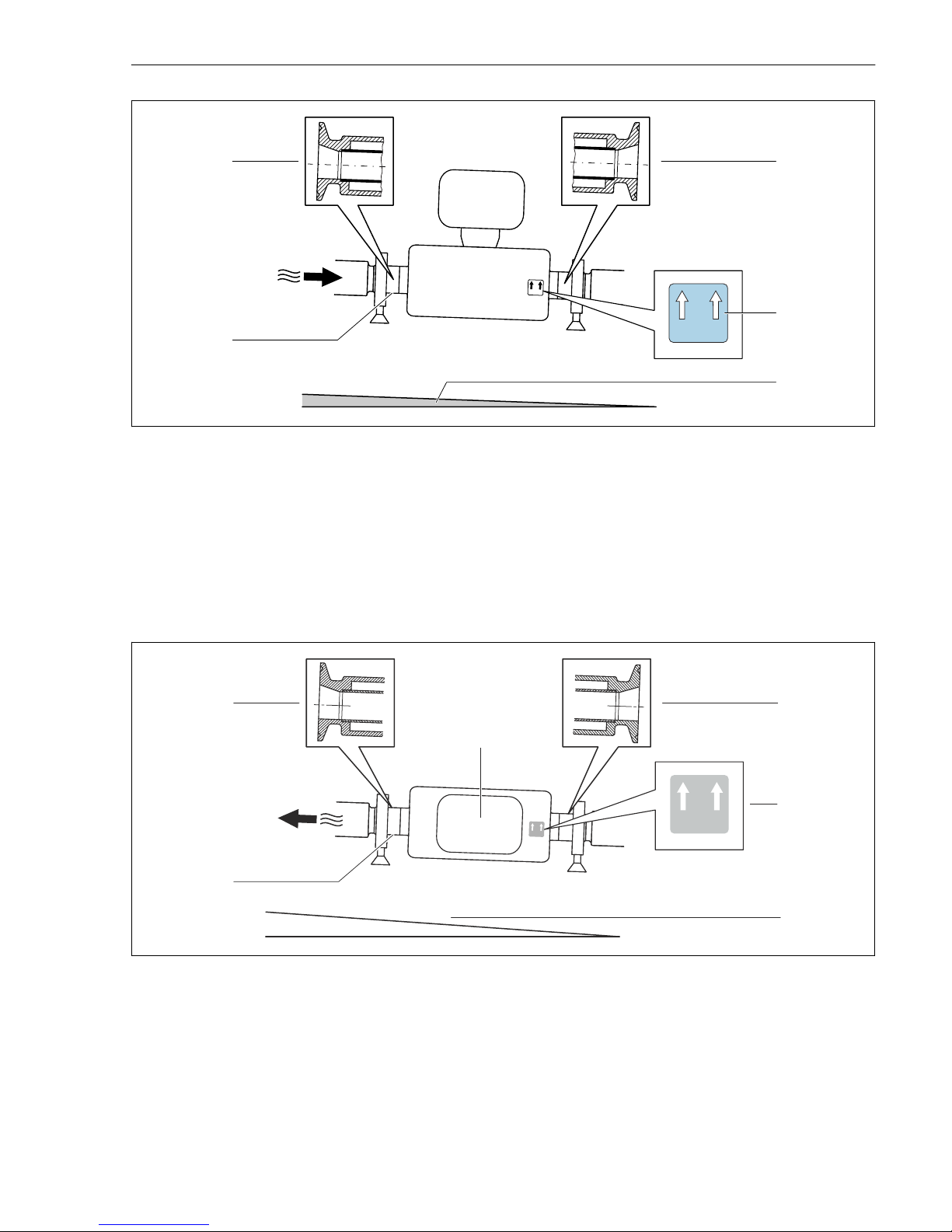
Complete drainability guaranteed (Promass I, P)
When the sensor is installed in a horizontal line, eccentric clamps can be used to ensure
complete drainability. When the system is pitched in a specific direction and at a specific
slope, gravity can be used to achieve complete drainability. The sensor must be mounted in
the correct position to ensure full drainability in the horizontal position. Markings on the
sensor show the correct mounting position to optimize drainability.
Promass I
Page 27
Proline Promass Installation
Endress+Hauser 27
2
3
1
A0030297
1 Eccentric clamp connection
2 "This side up" label indicates which side is up
3 Slope the device in accordance with the hygiene guidelines. Slope: approx. 2 % or 21 mm/m (0.24 in/
feet)
4 Line on the underside indicates the lowest point of the eccentric process connection.
Promass P
1
4
3
1
2
5
A0016583
1 Eccentric clamp connection
2 "This side up" label indicates which side is up
3 Slope the device in accordance with the hygiene guidelines. Slope: approx. 2 ° or 35 mm/m (0.42 in/
feet)
4 Line on the underside indicates the lowest point of the eccentric process connection.
5 Transmitter
Page 28
Installation Proline Promass
28 Endress+Hauser
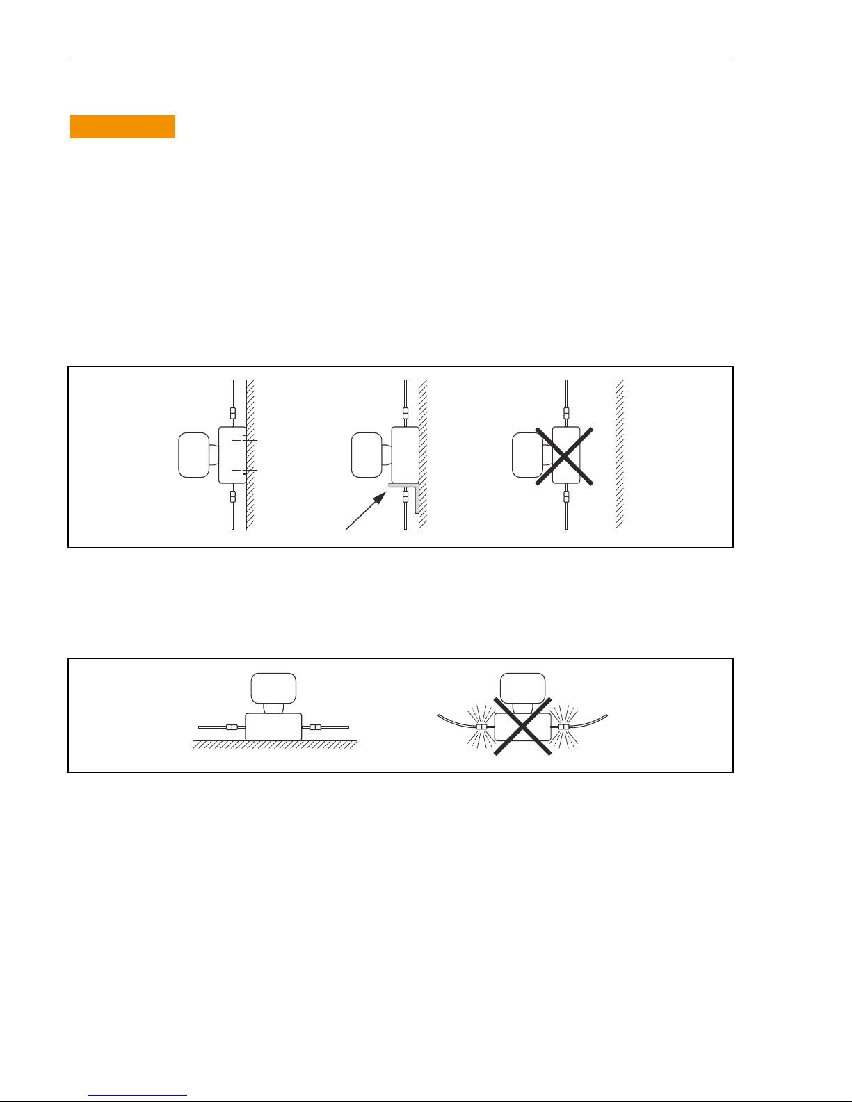
Wall and floor mounting (Promass A)
L
WARNING
Incorrect sensor mounting
Risk of injury if measuring tube breaks
‣
The sensor should never be installed in a pipe in a way that it is freely suspended
‣
Using the base plate, mount the sensor directly on the floor, wall or ceiling.
‣
Support the sensor on a securely mounted support base (e.g. angle bracket).
The following mounting versions are recommended for the installation.
Vertical
• Mounted directly on a wall using the base plate, or
• Device supported on an angle bracket mounted on the wall
A0019631
Horizontal
Device standing on a solid support base
A0019632
Post retainer (Promass A)
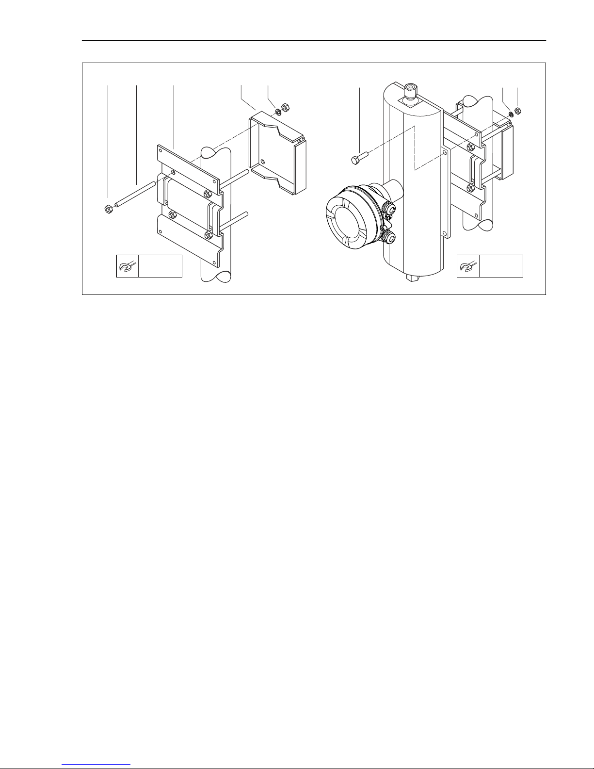
The post retainer mounting kit is used to secure the device to a pipe or post (order code for
"Accessories", option PR).
Page 29
Proline Promass Installation
Endress+Hauser 29
10 mm13 mm
1
2
3
4
5
6
7 8
A0019746
10 Post retainer mounting kit
1 8 x hexagonal nut M8 × 0.8
2 4 x threaded bolt M8 × 150
3 1 x post retaining plate
4 1 x post securing plate
5 4 x spring washer M8
6 4 x hexagon bolt M6 × 20
7 4 x spring washer M6
8 4 x hexagonal nut M6 × 0.8
Zero point adjustment
All measuring devices are calibrated in accordance with state-of-the-art technology.
Calibration takes place under reference conditions . Therefore, a zero point adjustment in the
field is generally not required.
Experience shows that zero point adjustment is advisable only in special cases:
• To achieve maximum measuring accuracy even with low flow rates
• Under extreme process or operating conditions (e.g. very high process temperatures or very
high-viscosity fluids).
5.2 Mounting the measuring device
5.2.1 Required tools
For transmitter
• For turning the transmitter housing: Open-ended wrench8 mm
• For opening the securing clamps: Allen key3 mm
• For turning the transmitter housing: Open-ended wrench8 mm
• For opening the securing clamps: Allen key3 mm
Page 30
Installation Proline Promass
30 Endress+Hauser
For mounting on a post:
• Proline 500 – digital transmitter
– Open-ended wrench AF 10
– Torx screwdriver TX 25
• Proline 500 transmitter
Open-ended wrench AF 13
For wall mounting:
Drill with drill bit ⌀ 6.0 mm
For sensor
For flanges and other process connections: Corresponding mounting tools
5.2.2 Preparing the measuring device
1. Remove all remaining transport packaging.
2. Remove any protective covers or protective caps present from the sensor.
3. If present, remove transport protection of the rupture disk.
4. Remove stick-on label on the electronics compartment cover.
5.2.3 Mounting the measuring device
L
WARNING
Danger due to improper process sealing!
‣
Ensure that the inside diameters of the gaskets are greater than or equal to that of the
process connections and piping.
‣
Ensure that the gaskets are clean and undamaged.
‣
Install the gaskets correctly.
1. Ensure that the direction of the arrow on the nameplate of the sensor matches the flow
direction of the fluid.
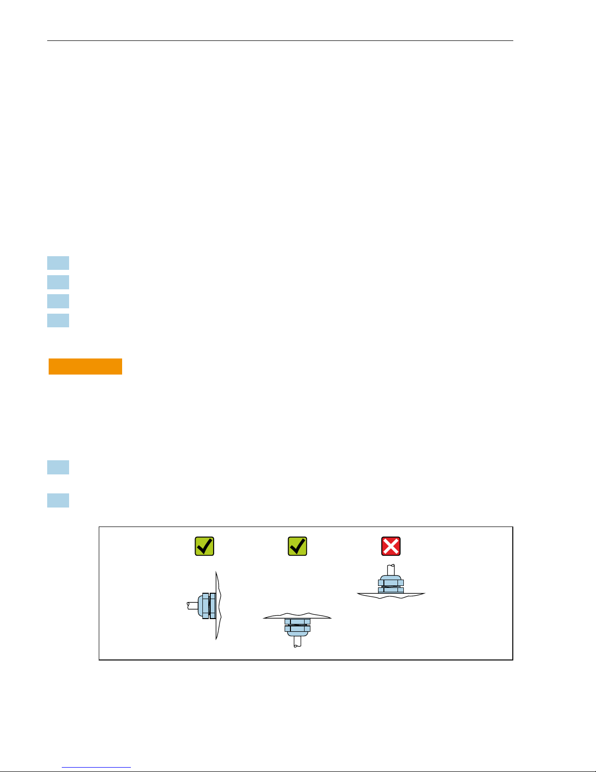
2. Install the measuring device or turn the transmitter housing so that the cable entries do
not point upwards.
A0029263
Page 31
Proline Promass Disposal
Endress+Hauser 31
5.3 Post-installation check
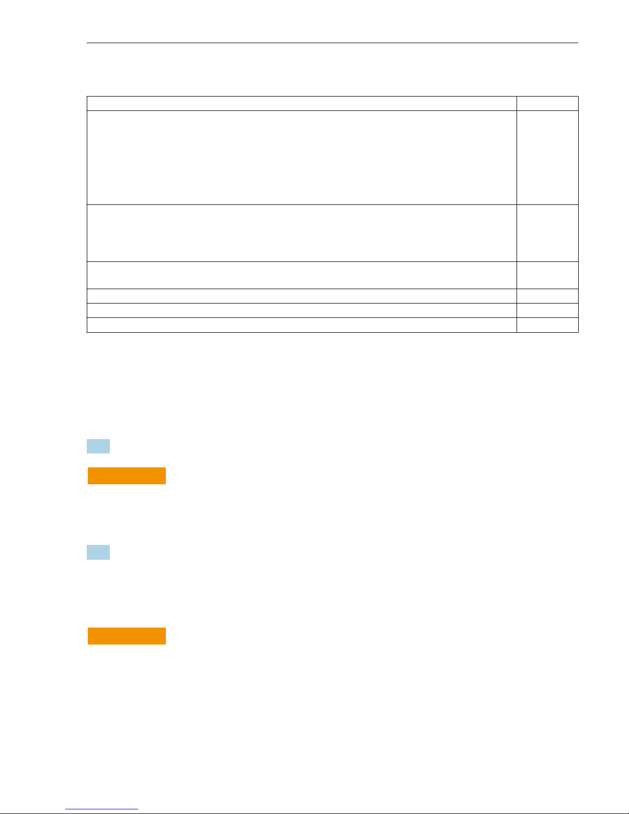
Is the device undamaged (visual inspection)?
Does the measuring device conform to the measuring point specifications?
For example:
• Process temperature
• Process pressure (refer to the chapter on "Pressure-temperature ratings" of the "Technical Information"
document on the CD-ROM provided)
• Ambient temperature
• Measuring range
Has the correct orientation for the sensor been selected ?
• According to sensor type
• According to medium temperature
• According to medium properties (outgassing, with entrained solids)
Does the arrow on the sensor nameplate match the direction of flow of the fluid through the piping
→ 15?
Are the measuring point identification and labeling correct (visual inspection)?
Is the device adequately protected from precipitation and direct sunlight?
Are the securing screw and securing clamp tightened securely?
6 Disposal
6.1 Removing the measuring device
1. Switch off the device.
L
WARNING
Danger to persons from process conditions.
‣
Beware of hazardous process conditions such as pressure in the measuring device, high
temperatures or aggressive fluids.
2. Carry out the mounting and connection steps from the "Mounting the measuring device"
and "Connecting the measuring device" sections in reverse order. Observe the safety
instructions.
6.2 Disposing of the measuring device
L
WARNING
Danger to personnel and environment from fluids that are hazardous to health.
‣
Ensure that the measuring device and all cavities are free of fluid residues that are
hazardous to health or the environment, e.g. substances that have permeated into crevices
or diffused through plastic.
Observe the following notes during disposal:
‣
Observe valid federal/national regulations.
‣
Ensure proper separation and reuse of the device components.
Page 32

www.addresses.endress.com
 Loading...