

Page 1
TI00264T/02/EN/15.19
71443142
Products Solutions Services
Technical Information
Thermowell
Omnigrad M TW13
Pipe thermowell
Flanged process connection
Application
TW13 is designed for use in the fine chemical s industry but can also be used for generic
applications.
Modular configuration according to DIN 43772 (form 2F/3F) enable a use in all
industrial processes with severe thermal and mechanical stresses.
Your benefits
• TW13 is a pipe thermowell.
• The process connection is flanged.
• Extension, immersion length and total length can be chosen according to process
requirements.
• A wide choice of dimensions, materials and process connections is available.
•Special versions can be manufactured according to customer requirements.
Page 2
Equipment architecture
TW13
Function and system design
1
4
5
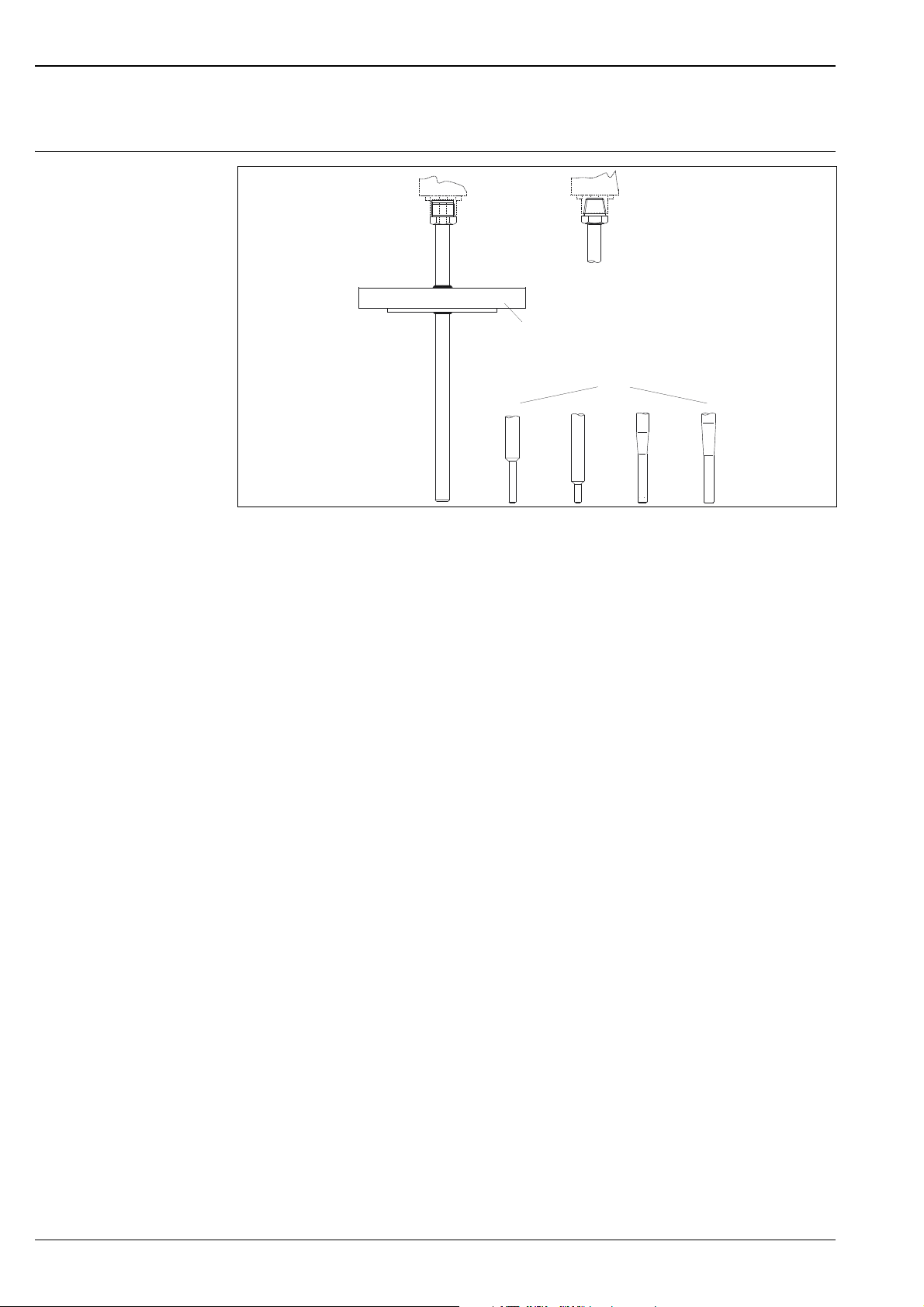
Equipment architecture of the Omnigrad M TW13
1 Thread M24x1.5
2 Thread 1/2" NPT
3 Various tip shapes - detailed information see chapter "Tip shape"
4 Process connection: flange
5 Jacket (protective sheath)
2
3
A0020843
The Omnigrad M TW13 thermowells are designed according to DIN 43772 and can therefore
guarantee a good level of resistance to the most typical and common industrial processes. The
thermowell is made from a pipe with a diameter of 9, 11, 12, 14 or 15 mm (0.35, 0.43, 0.47, 0.55 or
0.59 in). The end of the thermowell can be straight, tapered or reduced (stepped). An oversheath in
plastic can be supplied for thermowells with straight tip. The Omnigrad M TW13 thermowells can be
fitted on the plant (pipe or vessel) using a flanged process connection, which can be chosen from the
most common models.
2 Endress+Hauser
Page 3
TW13
Performance characteristics
Operating conditions Process pressure
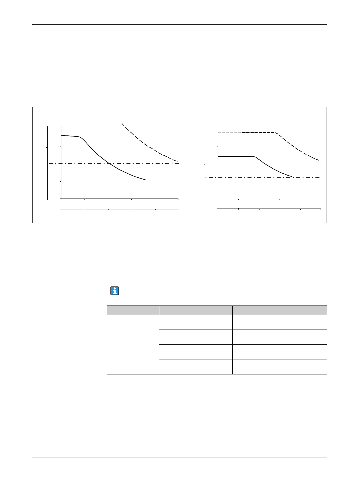
The pressure values to which the thermowell can be subjected at the various temperatures and
maximum permitted flow velocity are illustrated by the figure below. Occasionally, the pressure
loading capacity of the process connection can be considerably lower. The maximum allowable process
pressure for a specific thermometer is derived from the lower pressure value of the thermowell and
process connection.
P (PSI)
2900
2100
1400
700
P (bar)
200
150
P ~ PN100
max.
100
50
0
0
150 200 250 300 350 400
L (mm)
L (in)
8
10 12 14 16
Maximum permitted process pressure for tube diameter
A Medium water at T = 50 °C (122 °F)
B Medium superheated steam at T = 400 °C (752 °F)
LImmersion length
P Process pressure
___ Thermowell diameter 9 x 1 mm (0.35 in)
- - - Thermowell diameter 12 x 12.5 mm (0.47 in)
P (PSI)
2900
2100
1400
700
P (bar)
200
150
100
P ~ PN60
max.
50
0
0
150 200 250 300 350 400
L (mm)
L (in)
6
8
10 12
BA
14 166
A0013494
Note the limitation of the maximum process pressure to the flange pressure ratings indicated
in the following table.
Process connection Standard Max. process pressure
Flange EN1092-1 or ISO 7005-1 Depending on the flange pressure rating PNxx:
ANSI B16.5 Depending on the flange pressure rating 150
JIS B 2220 Depending on the flange pressure rating
DIN2526/7 Depending on the flange pressure rating
20, 40, 50 or 100 bar at 20 °C (68 °F)
or 300 psi at 20 °C (68 °F)
20K, 25K or 40K
PN40 at 20 °C (68 °F)
Endress+Hauser 3
Page 4

TW13
100 200 300 400 500
v (m/s)
A
100 200 300 400 500
v (m/s)
B
4
8
12 16 20
4
8
12 16
v (ft/s)
v (ft/s)
L (mm)
0
10
20
30
40
50
60
70
80
90
L (in)
20
0
30
65
100
130
165
200
230
260
295
0
5
10
15
20
25
30
35
40
45
0
15
30
50
65
80
100
115
130
145
L (mm)
L (in)
50
2
50
2
Maximum flow velocity
The highest flow velocity tolerated by the thermowell diminishes with increasing immersion length
exposed to the stream of the fluid. Detailed information may be taken from the figure below.
Flow velocity depending on the immersion length
A Medium water at T = 50 °C (122 °F)
B Medium superheated steam at T = 400 °C (752 °F)
LImmersion length
v Flow velocity
___ Thermowell diameter 9 x 1 mm (0.35 in)
- - - Thermowell diameter 12 x 12.5 mm (0.47 in)
A0008605
4 Endress+Hauser
Page 5

TW13
Material Thermowell and process connections.
The temperatures for continuous operation specified in the following table are only intended as
reference values for use of the various materials in air and without any significant compressive load.
The maximum operation temperatures are reduced considerably in some cases where abnormal
conditions such as high mechanical load occur or in aggressive media.
Material name Short form Recommended
max. temperature
for continuous use
in air
AISI 316L/1.4404
1.4435
AISI 316Ti/1.4571 X6CrNiMoTi17-12-2 700 °C (1292 °F)
Hastelloy
2.4819
Inconel600/2.4816 NiCr15Fe 1100 °C (2012 °F) • A nickel/chromium alloy with very good resistance to aggressive, oxidizing and
PTFE (Teflon) Polytetrafluorethylen 100 °C (212 °F) • Resistant to almost all chemicals
PVDF Polyvinylidene fluoride 80 °C (176 °F) • High stability
Tantalum - 250 °C (482 °F) • With the exception of hydrofluoric acid, fluorine and fluorides, tantalum
®
C276/
X2CrNiMo17-12-2
X2CrNiMo18-14-3
NiMo16Cr15 W 1100 °C (2012 °F) • A nickel-based alloy with good resistance to oxidizing and reducing
650 °C (1202 °F)
Properties
1)
• Austenitic, stainless steel
• High corrosion resistance in general
• Particularly high corrosion resistance in chlorine-based and acidic, nonoxidizing atmospheres through the addition of molybdenum (e.g. phosphoric
and sulfuric acids, acetic and tartaric acids with a low concentration)
• Increased resistance to intergranular corrosion and pitting
• Compared to 1.4404, 1.4435 has even higher corrosion resistance and a lower
delta ferrite content
1)
• Properties comparable to AISI316L
• Addition of titanium means increased resistance to intergranular corrosion
even after welding
• Broad range of uses in the chemical, petrochemical and oil industries as well as
in coal chemistry
• Can only be polished to a limited extent, titanium streaks can form
atmospheres, even at high temperatures
• Particularly resistant to chlorine gas and chloride as well as to many oxidizing
mineral and organic acids
reducing atmospheres, even at high temperatures
• Resistant to corrosion caused by chlorine gas and chlorinated media as well as
many oxidizing mineral and organic acids, sea water etc.
• Corrosion from ultrapure water
• Not to be used in a sulfur-containing atmosphere
• High temperature stability
• Max. operating pressure: <2 bar (29 psi)
• A high creepage stability under continuous demand
• Good cold properties
exhibits excellent resistance to most mineral acids and saline solutions
• Prone to oxidation and embrittlement at higher temperatures in air
1) Can be used to a limited extent up to 800 °C (1472 °F) for low compressive loads and in non-corrosive media.
Please contact your Endress+Hauser sales team for further information.
Endress+Hauser 5
Page 6

Components
M24x1.5
½“ NPT
L
E
1 2
Design, dimensions All dimensions in mm (in).
TW13
A0020855
Dimensions of the Omnigrad M TW13
1 M24x1.5 connection; sliding on the neck L Immersion length
2 ½" NPT connection; welded, not sliding on the neck ⌀D Diameter
ENeck tube length
The standard lengths of the neck are 80 or 145 mm (3.15 or 5.71 in). In accordance with standard DIN 43772, in the case of a thermowell with a diameter of ⌀12 mm (0.47 in) and a tapered tip (form 3F), the extension neck will respectively be 82 or 147 mm (3.23 or 5.79 in).
6 Endress+Hauser
Page 7

TW13
40 (1.6)
35 (1.34)
50 (1.97)
20 (0.8)
40 (1.6)
20
(0.8)
4
3
2
5
5 (0.2)
3.2
(0.13)
3 (0.12)
~3.5
(0.14)
6.1 (0.24)
3
(0.12)
3.2 (0.13)
3
(0.12)
7 (0.28)
1-2.5 (0.04-0.1)
9 (0.35)
(0.35)
(0.35)
2
(0.47)
6.5 (0.26)
1-2.5 (0.04-0.1)
7 (0.28)
1-2.5 (0.04-0.1)
11 (0.43)
1-2.5 (0.04-0.1)
10 (0.39)
1-2.5 (0.04-0.1)
6
1
L
D
K
d
b
f
Tip shape
Available thermowell tips (reduced, straight or tapered). Maximum surface roughness Ra ≤ 1.6 μm (62.9 μin)
Pos. No. Tip shape Insert diameter
1 Straight 6 mm (0.24 in)
2 Reduced, L ≥ 50 mm (1,97 in) 3 mm (0.12 in)
3 Reduced, L ≥ 30 mm (1,18 in)
4Tapered, L ≥ 70 mm (2.76 in)
5 Tapered DIN 43772-3F, L ≥ 90 m (3.54 in)
1)
1)
1)
3 mm (0.12 in)
3 mm (0.12 in)
6 mm (0.24 in)
6 Welded tip, weld quality according to EN ISO 5817 - quality class B
1) not with material Hastelloy® C276/2.4819 and Inconel600
Weight From 1.5 to 4.0 kg (3.3 to 8.8 lbs) for standard options.
Process connection Standard connections are available as weld-in connection (without flange) or with flange.
The following figure shows the basic dimensions of the available flanges.
A0019347
Endress+Hauser 7
Basic dimensions of the flange process connections
For detailed information on the flange dimensions refer to the following flange standards:
•ANSI/ASME B16.5
• ISO 7005-1
A0010471
Page 8

• EN 1092-1
L
1
L
2
3
4
h
• JIS B 2220 : 2004
• DIN 2526/7
The flange material should be the same as of the stem of the thermowell. For this reason, connections
are available both in SS 316L/1.4404 and in SS 316Ti/1.4571. Models in Hastelloy® C have flanges in
basic material SS 316L and a disc in Hastelloy® C on the surface in contact with the process media.
Installation conditions
Orientation No restrictions.
Installation instructions
TW13
A0020859
Installation examples
1 - 2: In pipes with a small cross section the sensor tip should reach or extend slightly past the center line of the pipe (= L)
3 - 4: Tilted installation
The immersion length of the thermometer influences the accuracy. If the immersion length is too small
then errors in the measurement are caused by heat conduction via the process connection and the
container wall. If installing into a pipe then the immersion length should be half of the pipe diameter,
if possible (see 1 and 2). A further solution could be an angled (tilted) installation (see 3 and 4). When
determining the immersion length all thermometer parameters and the process to be measured must
be taken into account (e.g. flow velocity, process pressure).
• Installation possibilities: Pipes, tanks or other plant components
• Recommended minimum immersion length = 80 to 100 mm (3.15 to 3.94 in)
The immersion length should correspond to at least 8 times of the thermowell diameter.
Example: Thermowell diameter 12 mm (0.47 in) x 8 = 96 mm (3.8 in). A standard immersion length
of 120 mm (4.72 in) is recommended.
• ATEX certification: Always take note of the installation regulations!
8 Endress+Hauser
Page 9

TW13
Certificates and approvals
CE mark The device meets the legal requirements of the EC directives if applicable. Endress+Hauser confirms
that the device has been successfully tested by applying the CE mark.
PED approval The thermowell complies with paragraph 3.3 of the Pressure Equipment Directive (97/23/CE) and is
not marked separately.
Material certification The material certificate 3.1 (according to standard EN 10204) can be directly selected from the sales
structure of the product and refers to the parts of the sensor in contact with the process fluid. Other
types of certificates related to materials can be requested separately. The "short form" certificate
includes a simplified declaration with no enclosures of documents related to the materials used in the
construction of the single sensor and guarantees the traceability of the materials through the
identification number of the thermometer. The data related to the origin of the materials can
subsequently be requested by the client if necessary.
Test on thermowell Thermowell pressure tests are carried out in accordance with the specifications in the DIN 43772
standard. With regards to thermowells with tapered or reduced tips that do not comply with this
standard these are tested using the pressure of corresponding straight thermowells. Sensors certified
for use in Ex Zones, are always tested to pressures according to the same criteria. Tests according to
other specifications can be carried out on request. Dye penetration tests verify the absence of cracks on
the thermowell welding.
Ordering information
Detailed ordering information is available from the following sources:
• In the Product Configurator on the Endress+Hauser website:
www.endress.com → Select country → Instruments → Select device → Product page function:
Configure this product
• From your Endress+Hauser Sales Center:
www.endress.com/worldwide
Product Configurator - the tool for individual product configuration:
• Up-to-the-minute configuration data
• Depending on the device: Direct input of measuring point-specific information such as
measuring range or operating language
• Automatic verification of exclusion criteria
• Automatic creation of the order code and its breakdown in PDF or Excel output format
• Ability to order directly in the Endress+Hauser Online Shop
Endress+Hauser 9
Page 10

www.addresses.endress.com
 Loading...