

Page 1
TI 00263T/02/EN/13.19
71443140
Products Solutions Services
Technical Information
Thermowell
omnigrad M TW12
Pipe thermowell
Sliding process connection
Application
Omnigrad M TW 12 thermowells are designed for the use in the
fine chemicals industry but can also be used for generic
tions.
Thanks to its modular configuration, defined in standard DIN
43772 (form 2/3), the TW 12 thermowell for temperature sensors is suitable for almost all industrial processes.
applica-
Features and benefits
• SS 316L/1.4404 e SS 316Ti/1.4571 for "wetted" parts
• The most common compression fittings are supplied as standard; others are available on request.
• Customized immersion length
• Surface finishing Ra < 0.8 μm
• Tip of the thermowell with a reduced diameter or tapered for
a faster response time
• Material certification (3.1.B)
• Pressure test
Page 2
Areas of application
NPT
M
TW12_g_gd_13_xx_01
• Fine chemicals industry
• Light energy industry
• Food industry
• General industrial services
Function and system design
Equipment architecture The design of the thermowell is based on standard DIN 43772 and can therefore guarantee a good
level of resistance to the most typical and common industrial processes.
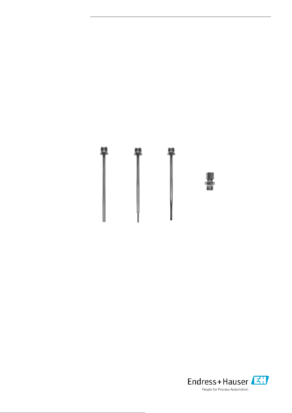
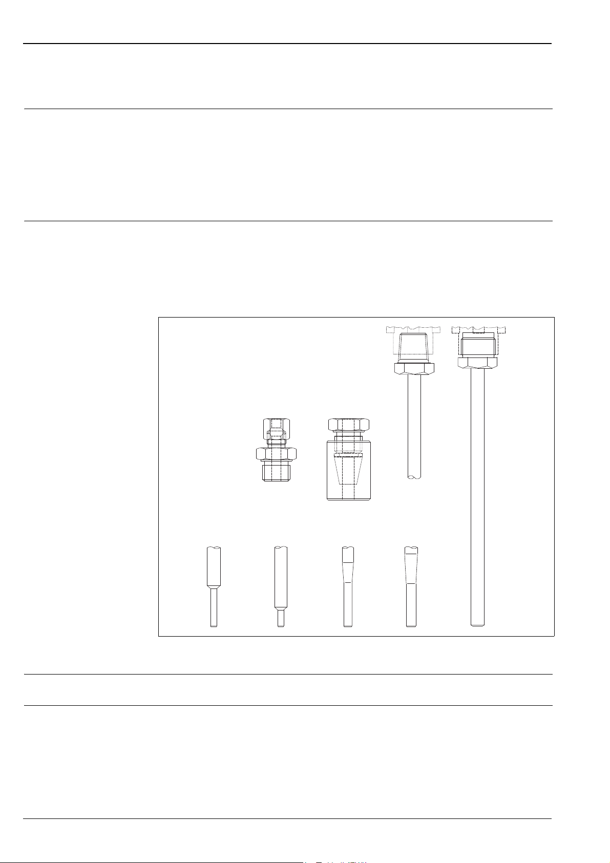
The thermowell is made from a pipe with a diameter of 9, 11 or 12 mm. The final part can be straight,
tapered (i.e. with a gradual reduction of the stem achieved thanks to a swaging procedure), or reduced
(stepped).
The TW 12 can be fitted onto the plant (tube or tank) through the use of a compression fitting, which
can be chosen from the most common models (see section "Structure of the components").
Fig. 1: TW 12 with several types of process connections and end parts of the thermowell.
Material Wetted parts in SS 316L/1.4404 or SS 316Ti/1.4571.
Weight From 0.5 to 1.5 Kg for standard options.
2
Page 3
Performance
Grafic_g_gd_05_en_06
Grafic_g_gd_05_en_16
Operating conditions Process temperature
• Sleeve in SS (TA 50 compression fitting) max 500°C
• Sleeve in PTFE (TA 50 compression fitting) max 200°C
• Sleeve in Viton® (TA70 compression fitting) max 180°C
If the thermowell is welded to the plant, the acceptable temperature for the process is:
• 316L/1.4404 -200 ÷ 600°C
• 316Ti/1.4571 -200 ÷ 800°C.
Maximum process pressure
• Sleeve in SS (TA 50 compression fitting ) 4 MPa (40 bar) at 20°C
• Sleeve in PTFE (TA 50 compression fitting) 1 MPa (10 bar) at 20°C
• Sleeve in Viton® (TA 70 compression fitting) 2 MPa (20 bar) at 20°C
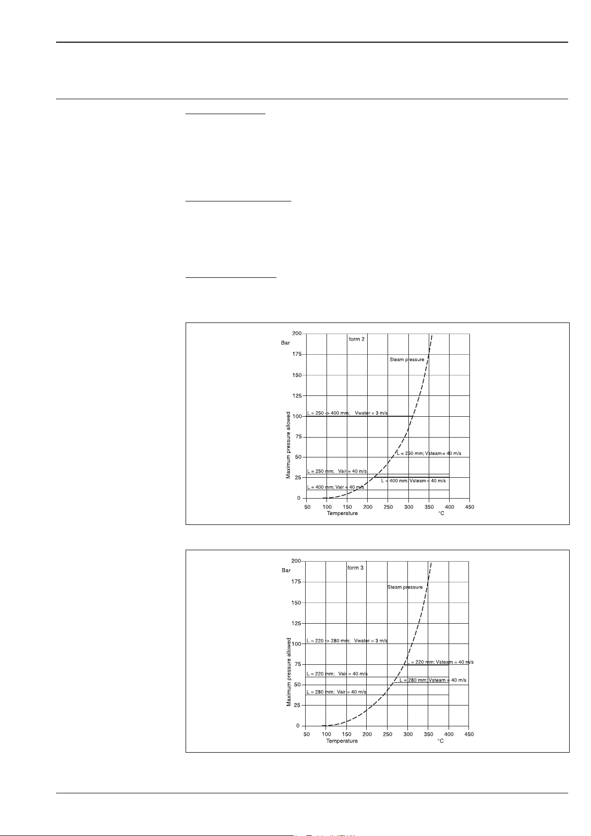
If the thermowell is welded to the plant, the pressure values to which the
various temperatures are illustrated by the drawings in figures 2 and 3.
Maximum flow velocity
The highest flow velocity tolerated by the thermowell decreases as the length of the well/probe, exposed to the stream of the fluid, increases. Some information may be taken from the drawing in figures
2 and 3.
thermowell can be subjected
at
Fig. 2: Pressure/temperature drawing for thermowell with a straight pipe Ø11 in SS 316Ti/1.4571
Fig. 3: Pressure/temperature drawing for thermowell with stepped pipe Ø12 mm in SS 316Ti/1.4571
3
Page 4

Installation
h
L
d
TW12xx_g_id_07_it_01
Measurement range The Omnigrad M TW 12 thermowells can be mounted on pipes or vessels or other plant parts that may
require them.
The interface components for the connection to the process and the related gaskets are not normally
provided with the sensors and must be purchased by the customer.
Immersion length may influence the accuracy of the measurement. If the immersion length is too low,
an error may be generated in the temperature recorded due to the lower temperature of the process
fluid near to the walls and heat transfer, which takes place through the sensor stem. The incidence of
such an error can be relevant if there is a large difference between the process temperature and ambient temperature. In order to avoid this source of inaccuracy, the thermowell should have a small diameter and the immersion length (L) should be, if possible, at least 80÷100 mm.
For pipes with a small section, it is necessary to make sure that the tip of the probe reaches or slightly
exceeds, if possible, the axis line of the duct (see fig. 4A-4B). Insulation of the outer part of the sensor
reduces the effect produced by a low immersion length. Another solution may be a tilted installation
(see fig. 4C-4D). For use in the food industry, it is best to follow the rule h <= d/2.
Fig. 4: Installation examples
As far as corrosion is concerned, the base materials for "wetted" parts (SS 316L/1.4404, SS 316Ti/
1.4571 for the pipe, SS 316/1.4401 for the compression fittings and for several types of sleeves) are
able to tolerate the most common corrosive agents up to the highest temperatures. For further information on specific applications, please contact the E+H Customer Service.
4
Page 5

System components
Straight
1
TW12_g_gd_13_en_01
Process connection Standard compression fittings (in SS 316/1.4401) are available with the following connections:
• threaded, G 1/2” and G 1”, with stainless steel or PTFE sleeve (TA 50)
• welded, with sleeve in Viton® (TA 70)
Other versions may be supplied on request.
Figure 5 shows the base dimensions.
Model F L (mm) C (mm) B (mm)
TA50
TA70 Weld-in 76 34 -
Fig. 5: Base dimensions of process connections
G1” 70 - 25
G1/2” 47 - 15
TA5070_G_gd_15_xx_01
The immersion length of the part of pipe in contact with the process fluid is available in the standard
dimensions indicated in standard DIN 43772 and in the most commonly used ones. Immersion length
can also be customised within a range of values (see "Sales structure" at the end of this document).
The surface finishing (Ra) is 0.8 μm. The different types of tips (reduced or tapered) are described in
figure 6.
The M24x1.5 connection, situated in the upper part of the neck, enables to orient the head of the sensor. This option is not available with 1/2” NPT fittings.
Fig. 6: Functional components
1 Welded tip, weld quality according to EN ISO 5817 - quality class B
5
Page 6

Certificates & approvals
PED approval The Pressure Equipment Directive (97/23/CE) is respected. As paragraph 2.1 of article 1 is not appli-
cable to this kind of instruments, the marking 4 is not mandatory for TW 12 models used for generic
applications.
Material certification The material certificate 3.1.B (compliant standard EN 10204) can be directly selected from the sale
structure of the product and refers to the parts of the thermowell in contact with the process fluid.
Other types of certificates related to materials can be required separately.
The "short form" certificate includes a simplified declaration, with no enclosures of documents, related
to the materials used in the construction of the thermowell and guarantees the traceability of the
materials through the identification number of the product. The data related to the origin of the materials can subsequently be requested by the customer if necessary.
Test on the thermowell The pressure tests are carried out at ambient temperature in order to verify the resistance of the ther-
mowell to the specifications indicated by standard DIN 43772. For thermowells that do not
this standard (with a reduced tip, a tapered tip on a 9 mm pipe, special dimensions, ….)
corresponding straight pipe with similar dimensions is verified. Tests at different pressures can be carried out on request.
, the pressure of the
Ordering information
comply with
Detailed ordering information is available from the following sources:
• In the Product Configurator on the Endress+Hauser website:
www.endress.com → Select country → Instruments → Select device → Product page function:
Configure this product
• From your Endress+Hauser Sales Center:
www.endress.com/worldwide
Product Configurator - the tool for individual product configuration:
• Up-to-the-minute configuration data
• Depending on the device: Direct input of measuring point-specific information such as
measuring range or operating language
• Automatic verification of exclusion criteria
• Automatic creation of the order code and its breakdown in PDF or Excel output format
• Ability to order directly in the Endress+Hauser Online Shop
6
Page 7

Page 8

www.addresses.endress.com
 Loading...