

Page 1
TI00070R/09/EN/02.18
71409786
Products Solutions Services
Technical Information
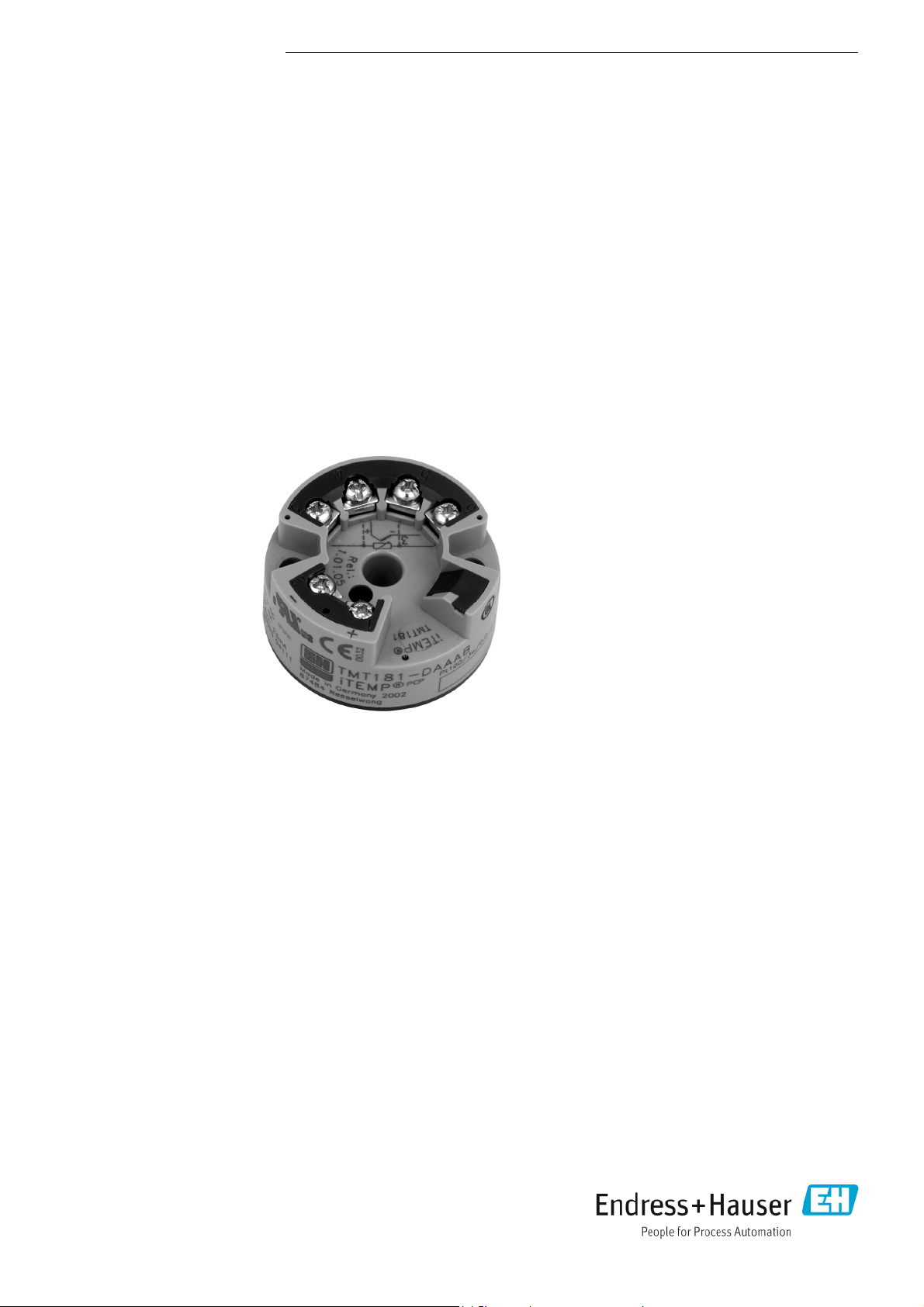
iTEMP TMT181
Universal head transmitter for resistance thermometers
(RTD), thermocouples, resistance and voltage transmitters,
PC programmable, for installation in a terminal head form B
Application
• PC programmable (PCP) temperature head transmitter for
converting various input signals into an scalable 4 to 20 mA
analog output signal
• Input:
Resistance thermometer (RTD)
Thermocouple (TC)
Resistance transmitter ()
Voltage transmitter (mV)
• Online configuration using PC with TXU10-AA configuration
kit (accessory)
Your benefits
• Universally PC programmable for various signals
• 2 wire technology, 4 to 20 mA analog output
• High accuracy in total ambient temperature range
• Fault signal on sensor break or short circuit, presettable to
NAMUR NE 43
• EMC to NAMUR NE 21, CE
• UL recognized component to UL 3111-1
• Marine approval
– Ex certification
– ATEX Ex ia and dust ex zone 22 in compliance with
EN 50281-1
–FM IS
–CSA IS
• Galvanic isolation
• Online configuration during measurement using SETUP
connector
• Customer-specific linearization
• Adjustment of characteristic curve
•Output simulation
Page 2
iTEMP TMT181
Function and system design
Measuring principle Electronic measurement and conversion of input signals in industrial temperature measurement.
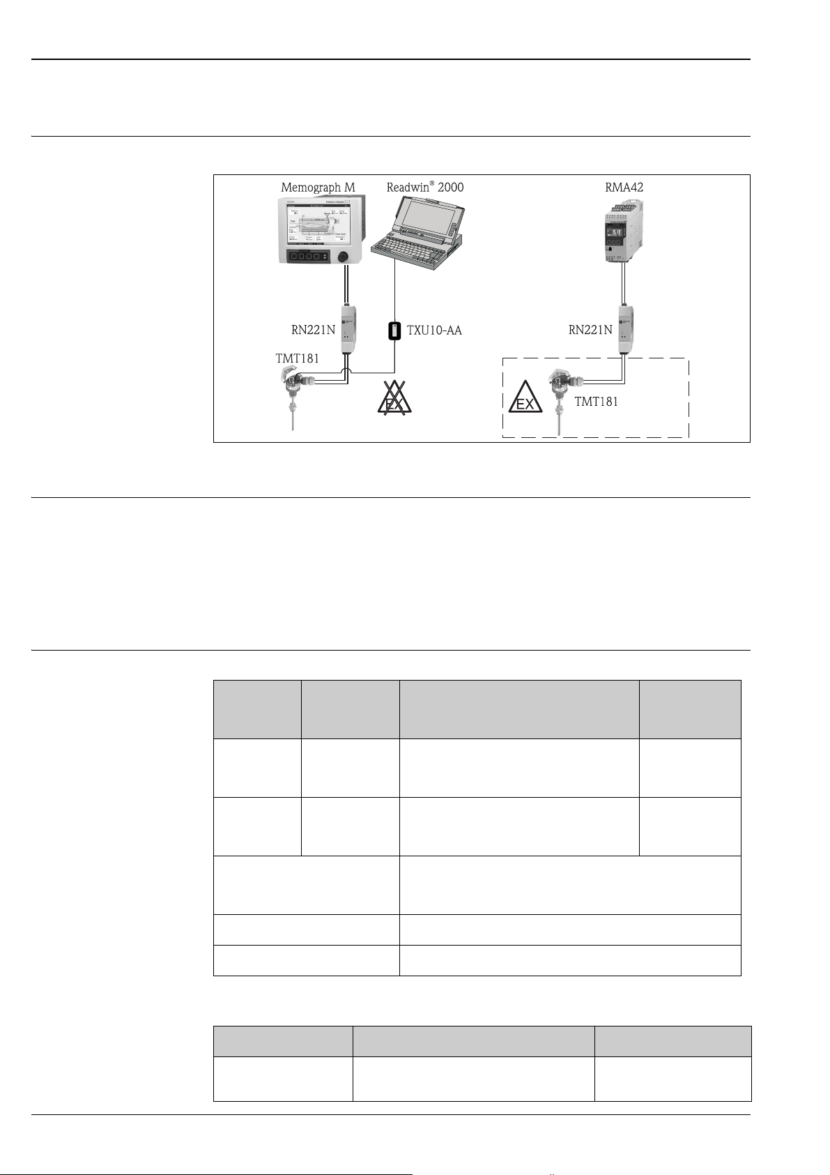
Application example TMT181
a0016026
Measuring system The iTEMP PCP TMT181 temperature head transmitter is a two wire transmitter with an analog
output. It has measurement input for resistance thermometers (RTD) in 2-, 3- or 4-wire connection,
thermocouples and voltage transmitters. Setting up of the TMT181 is done using the TXU10-AA
configuration kit.
Input
Input signal Resistance thermometer (RTD)
Type Measurement ranges min.
measurement
range
as per IEC 751
(a = 0.00385)
as per
DIN 43760
(a = 0.00618)
Connection type 2-, 3- or 4-wire connection
Pt100
Pt500
Pt1000
Ni100
Ni500
Ni1000
-200 up to 850 °C
-200 up to 250 °C
-200 up to 250 °C)
-60 up to 180 °C
-60 up to 150 °C
-60 up to 150 °C
cable resistance compensation possible in the 2 wire system
(0 up to 20 ).
(-328 up to +1562 °F)
(-328 up to +482 °F)
(-328 up to +482 °F
(-76 up to +356 °F)
(-76 up to +302 °F)
(-76 up to +302 °F)
10 K (18 °F)
10 K (18 °F)
10 K (18 °F)
10 K (18 °F)
10 K (18 °F)
10 K (18 °F)
Sensor cable resistance max. 11 per wire
Sensor current ≤ 0.6 mA
Resistance transmitter ()
Type Measurement ranges min. measurement range
Resistance () 10 up to 400
10 up to 2000
10
100
2 Endress+Hauser
Page 3

iTEMP TMT181
Thermocouple (TC)
Type Measurement ranges min.
1)
as per NIST
Monograph
175, IEC 584
as per ASTME
E988
as per
DIN 43710
w/o MoRe5-MoRe41 0 up to 2000 °C (32 up to 3632 °F) 500 °C (900 °F)
Cold junction internal (Pt100) or external (0 up to 80 °C (32 up to 176 °F))
Accuracy of cold junction ± 1 K (± 1.8 °F)
Sensor current 30 nA
1) Higher measurement error for temperatures below 300 °C (572 °F).
B (PtRh30-PtRh6)
E (NiCr-CuNi)
J (Fe-CuNi)
K (NiCr-Ni)
N (NiCrSi-NiSi)
R (PtRh13-Pt)
S (PtRh10-Pt)
T (Cu-CuNi)
C (W5Re-W26Re)
D (W3Re-W25Re)
L (Fe-CuNi)
U (Cu-CuNi)
0 up to +1820 °C
-200 up to +915 °C
-200 up to +1200 °C
-200 up to +1372 °C
-270 up to +1300 °C
0 up to +1768 °C
0 up to +1768 °C
-200 up to +400 °C
0 up to 2320 °C
0 up to 2495 °C
-200 up to +900 °C
-200 up to +600 °C
(32 up to 3308 °F)
(-328 up to 1679 °F)
(-328 up to 2192 °F)
(-328 up to 2501 °F
(-454 up to 2372 °F)
(32 up to 3214 °F)
(32 up to 3214 °F)
(-328 up to 752 °F)
(32 up to 4208 °F)
(32 up to 4523 °F)
(-328 up to 1652 °F)
(-328 up to 1112 °F)
measurement
range
500 °C (900 °F)
50 °C (90 °F)
50 °C (90 °F)
50 °C (90 °F)
50 °C (90 °F)
500 °C (900 °F)
500 °C (900 °F)
50 °C (90 °F)
50 °C (90 °F)
50 °C (90 °F)
50 °C (90 °F)
50 °C (90 °F)
Voltage transmitter (mV)
Designation Measurement ranges min. measurement
Millivolt transmitter
(mV)
Output
Output signal Current output
4 up to 20 mA, 20 to 4 mA
Signal on alarm
Measurement range undercut linear drop to 3.8 mA
Exceeding measurement range linear rise to 20.5 mA
Sensor breakage, sensor short circuit
1) Not for thermocouple
range
-10 up to 100 mV 5 mV
1)
3.6 mA or 21.0 mA
Load Max. load: (V
- 8 V) / 0.025 A
supply
Transmission behavior Temperature linear, resistance linear, voltage linear
Galvanic isolation I/O: U = 2 kV AC
Endress+Hauser 3
Page 4
Filter 1st degree digital filter: 0 up to 8 s
Current limit ≤ 25 mA
iTEMP TMT181
Switch-on delay 4 s (I
Power supply
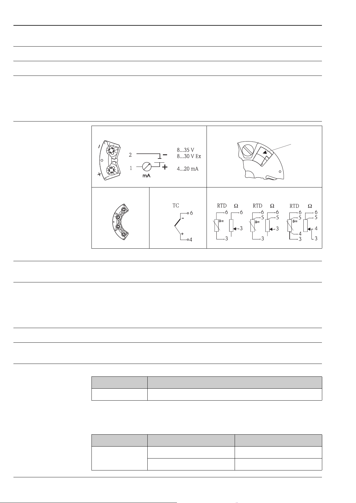
Terminal assignment
Voltage supply and current output SETUP connector
Sensor connection 2-wire 3-wire 4-wire
= 3.8 mA during swich-on)
a
a0016012 a0016011 a0 016010
a0016013 a0016014
Supply voltage 8 up to 35 V DC, polarity protected
Ex version: 8 up to 30 V DC
Residual ripple Permissible residual ripple USS ≤ 5V at Ub 13 V, f
Performance characteristics
Response time 1 s
Reference operating conditions
Maximum measured error Resistance thermometer (RTD)
Calibration temperature 23 °C ± 5 K (73.4 °F ± 9 °F)
Type Measurement accuracy
Pt100, Ni100 0.2 K (0.36 °F) or 0.08 %
1) % is related to the adjusted measurement range (the value to be applied is the greater).
1)
Resistance transmitter ()
Type Measurement accuracy
1)
= 1 kHz
max
Measurement range
Resistance ± 0.1 or 0.08 % 10 up to 400
± 1.5 or 0.12 % 10 up to 2000
4 Endress+Hauser
Page 5

iTEMP TMT181
1) % is related to the adjusted measurement range (the value to be applied is the greater).
Thermocouple (TC)
Type Measurement accuracy
K, J, T, E, L, U
N, C, D
S, B, R, MoRe5MoRe41
Influence of the
internal reference
junction
1) % is related to the adjusted measurement range (the value to be applied is the greater).
typ. 0.5 K (0.8 °F) or 0.08 %
typ. 1.0 K (1.8 °F) or 0.08 %
typ. 2.0 K (3.6 °F) or 0.08 %
Pt100 DIN IEC 751 Kl. B
1)
Voltage transmitter (mV)
Type Measurement accuracy
Millivolt transmitter ± 20 μV or 0.08 % -10 up to 100 mV
Influence of the supply
voltage
Influence of the load ≤ ± 0.02 %/100
1) % is related to the adjusted measurement range (the value to be applied is the greater).
2) All data is related to a measurement end value (FSD) of 20 mA.
≤ ± 0.01 %/V deviation from 24 V
1)
2)
Measurement range
2)
Long-term drift 0.1 K/year (0.18 °F/year)
Influence of ambient temperature
Td = temperature drift
T = deviation of ambient temperature from reference condition
1)
or 0.05 %/year
1)2)
For temperatures in °F, divide the result by 1.8.
Resistance thermometer (RTD):
= ± (15 ppm/K * max. measurement range + 50 ppm/K * preset measurement range) * T
T
d
Resistance thermometer Pt100:
= ± (15 ppm/K * (range end value+200) + 50 ppm/K * preset measuring range) * T
T
d
Thermocouple (TC):
T
= ± (50 ppm/K * max. measurement range + 50 ppm/K * preset measurement range) * T
d
Installation
Mounting location Terminal head as per DIN EN 50446 Form B; field housing TAF10
Orientation No restrictions
1) under reference conditions
2) % is related to the adjusted measurement range (the value to be applied is the greater).
Endress+Hauser 5
Page 6
iTEMP TMT181
Environment
Ambient temperature range -40 up to +85 °C (-40 up to +185 °F) (for Ex-areas, see Ex-certification or control drawings)
Storage temperature -40 up to +100 °C (-40 up to +212 °F)
Electromagnetic compatibility (EMC)
CE conformity
EMC to all relevant requirements of the IEC/EN 61326-series and NAMUR Recommendation EMC
(NE21). For details, refer to the Declaration of Conformity.
Maximum fluctuations during EMC-tests: <1% of measuring span.
Interference immunity to IEC/EN 61326-series, requirements for industrial areas
Interference emission to IEC/EN 61326-series, electrical equipment Class B
Mechanical construction
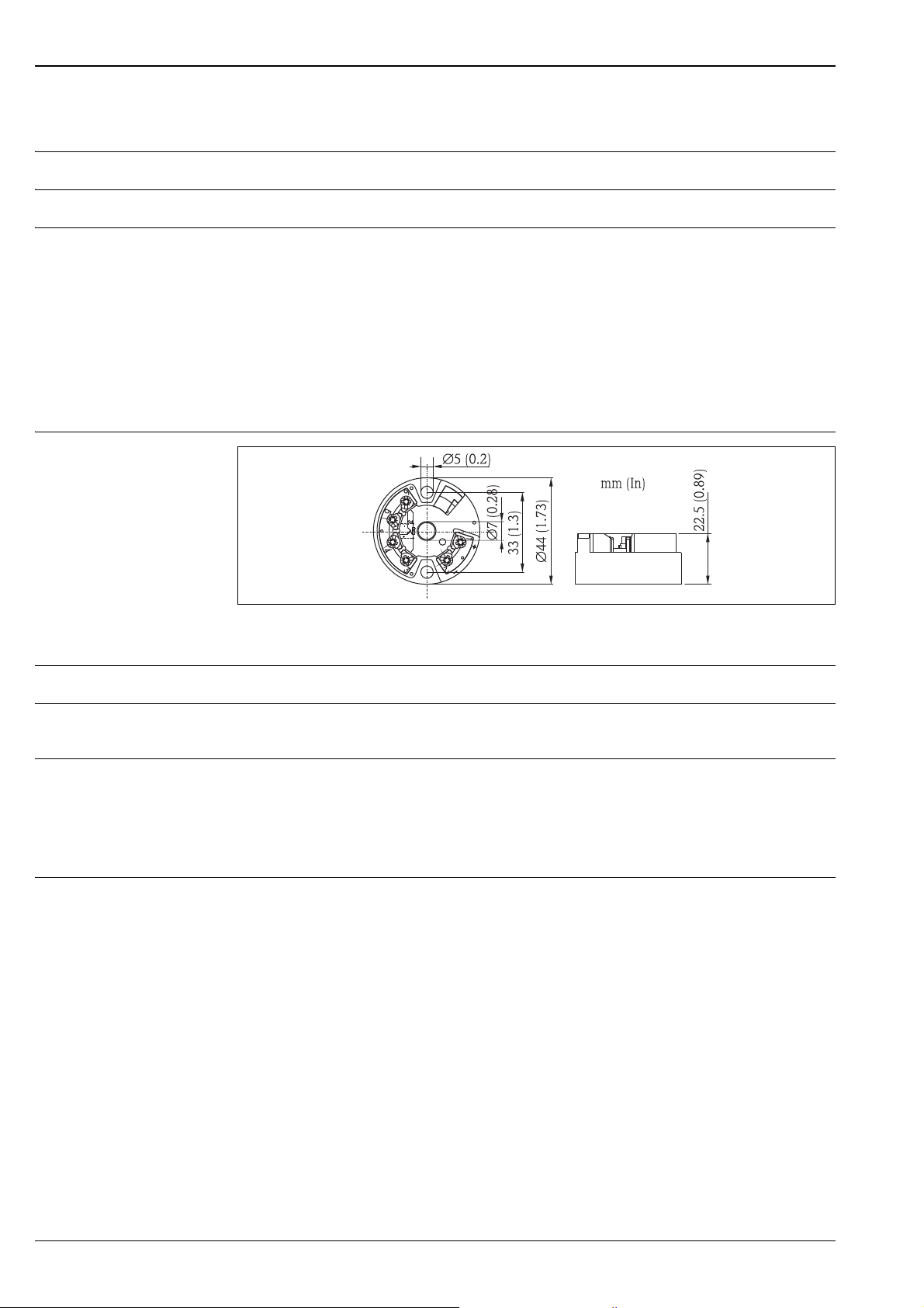
Design, dimensions
Dimensions of the head transmitter
Weight 40 g (1.41 oz.)
a0003233
Materials Housing: PC
Potting: PUR
Terminals Cable up to max. 1.75 mm² (16 AWG)
Operability
Operating concept Remote operation
Configuration kit TXU10-AA (accessory)
Interface cable plus PC software Readwin
Interface: PC interface connection cable TTL -/- RS232 with plug
Configurable parameters: sensor type and connection type, measurement dimension (°C/°F),
measurement ranges, internal/external cold junction, compensation of cable resistance for 2-wire
connection, signal on alarm, output signal (4 up to 20 mA/20 to 4 mA), digital filter (damping), offset,
measurement point identification (8 characters), output simulation.
®
2000
6 Endress+Hauser
Page 7

iTEMP TMT181
Certificates and approvals
CE mark This unit complies with the legal requirements laid out within the EU regulations.
Ex approval For further details on the available Ex versions (ATEX, CSA, FM, etc.), please contact your nearest E+H
sales organization. All relevant data for hazardous areas can be found in separate Ex documentation.
If required, please request copies from us or your Endress+Hauser sales organisztion.
Marine approval For further details on the available "Type Approval Certificiates" (DNVGL, BV, etc.), please contact your
nearest Endress+Hauser sales organisation. All relevant data for marine approval can be found in
separate "Type Approval Certificiates". If required, please request copies from us or your
Endress+Hauser sales organisation.
UL approval UL recognized component (see www.ul.com/database, search for Keyword "E225237")
Ordering information
Product structure Detailed ordering information is available from the following sources:
• In the Product Configurator on the Endress+Hauser website: www.endress.com -> Click "Corporate"
-> Select your country -> Click "Products" -> Select the product using the filters and search field ->
Open product page -> The "Configure" button to the right of the product image opens the Product
Configurator.
• From your Endress+Hauser Sales Center: www.addresses.endress.com
Product Configurator - the tool for individual product configuration
• Up-to-the configuration
• Depending on the device: Direct input of measuring point-specific information such as
measuring range or operating language
• Automatic verification of exclusion criteria
• Automatic creation of the order code and its breakdown in PDF or Excel output format
• Ability to order directly in the Endress-Hauser Online Shop
Accessories
Device-specific accessories Configuration kit TXU10-AA
Interface cable plus PC software Readwin
Documentation
Standard documentation • Operating instructions KA141R/09
• ATEX Safety instructions:
– ATEX II1G: XA004R/09
– ATEX II3G: XA010R/09
– ATEX II3D: XA026R/09
®
2000
Endress+Hauser 7
Page 8

iTEMP TMT181
www.addresses.endress.com
 Loading...