

Page 1
TI00090R/09/en/14.19
71427748
Products Solutions Services
Technical Information
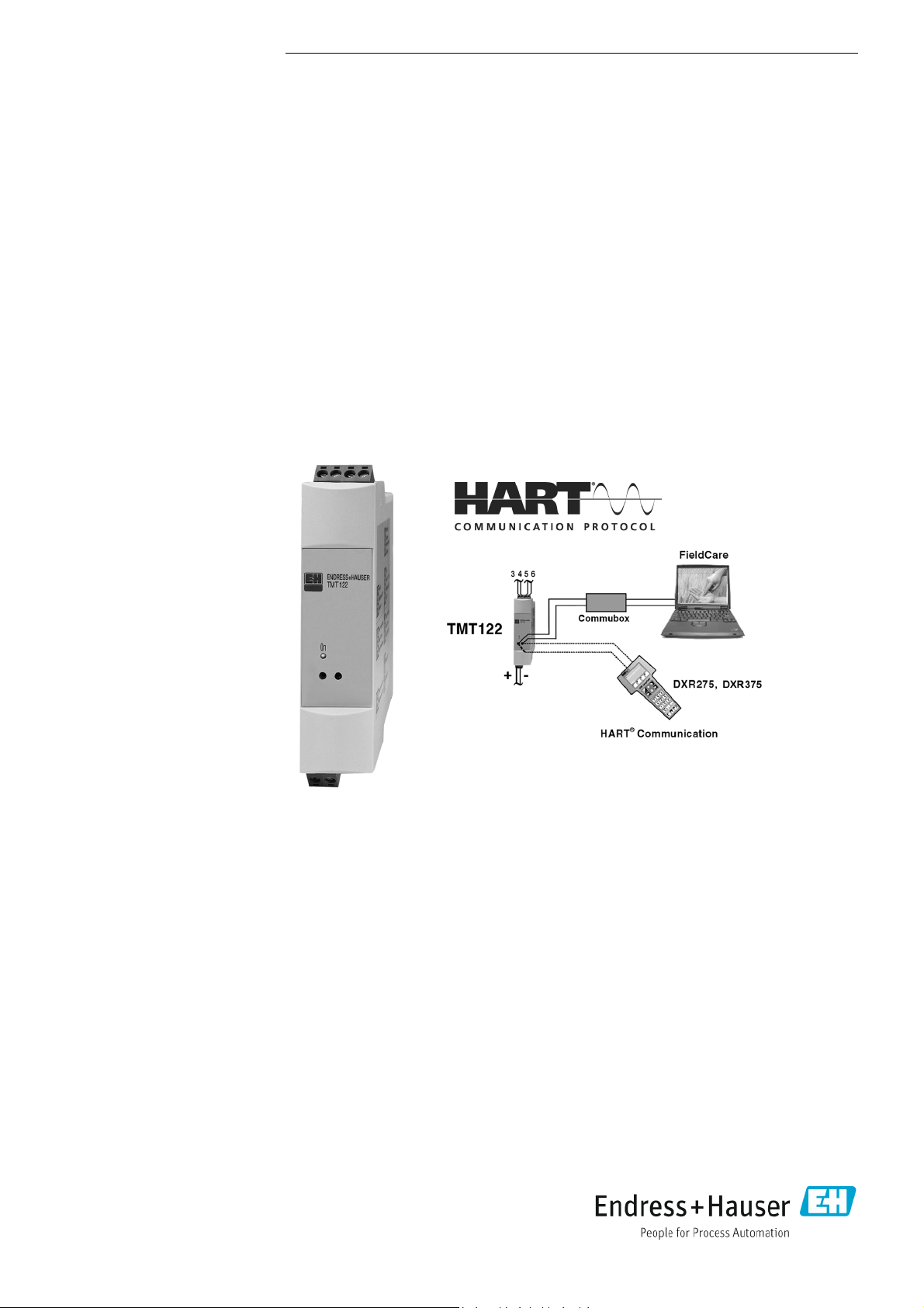
iTEMP HART® TMT122 DIN rail
Universal temperature transmitter for resistance thermometers (RTD), thermocouples, resistance and voltage
transmitters, incorporating HART® protocol
Application
• Temperature transmitter with HART® protocol for converting
various input signals into a scalable
4 to 20 mA analog output signal
• Input:
Resistance thermometer (RTD)
Thermocouple (TC)
Resistance transmitter ()
Voltage transmitter (mV)
®
•HART
• Installation on DIN rail according to IEC 60715
protocol for front end unit or panel unit
operation using the hand operating module (DXR375) or PC
(e.g. ReadWin® 2000 or FieldCare)
Your benefits
• Universal settings with HART
signals
• 2-wire technology, 4 to 20 mA analog output
• High accuracy in total ambient temperature range
• Fault signal on sensor break or short circuit,
presettable to NAMUR NE 43
• EMC to NAMUR NE 21, CE
• UL recognized component
• Ex-Certification:
- ATEX Ex ia
- CSA IS
- FM IS
• Marine approval
• Galvanic isolation
•Output simulation
• Min./max. process value indicator function
• Customer-specific linearization
• Linearization curve match
®
protocol for various input
Page 2

TMT122
Function and system design
Measurement principle Electronic measurement and conversion of input signals in industrial temperature measurement.
®
Measurement system The iTEMP HART
TMT122 DIN rail temperature transmitter is a 2-wire transmitter with an analog
output. It has measurement input for resistance thermometers (RTD) in 2-, 3- or 4-wire connection,
thermocouples (TC) and voltage transmitters. Setup of the device is done using the HART® protocol
with hand operating module (DXR375) or PC (configuration software ReadWin
®
2000 or FieldCare).
Input
Measured variable Temperature (temperature linear), resistance and voltage.
Measuring range Depending upon the sensor connection and input signal. The transmitter evaluates a number of diffe-
rent measurement ranges.
Type of input
Resistance
thermometer (RTD)
acc. to IEC 751 ( = 0.00835)
acc. to JIS C 1604-81 ( = 0.003916)
acc. to DIN 43760 ( = 0.006180)
Resistance transmitter Resistance 10 to 400
Thermocouples (TC) B (PtRh30-PtRh6)
Type Measurement ranges Min. measurement
Pt100
Pt500
Pt1000
Pt100
Ni100
Ni500
Ni1000
Connection type: 2-, 3- or 4-wire connection
Software compensation of cable resistance possible in the 2-wire system (0 to 30 )
Sensor cable resistance max. 40
C (W5Re-W26Re)
D (W3Re-W25Re)
E (NiCr-CuNi)
J (Fe-CuNi)
K (NiCr-Ni)
L (Fe-CuNi)
N (NiCrSi-NiSi)
R (PtRh13-Pt)
S (PtRh10-Pt)
T (Cu-CuNi)
U (Cu-CuNi)
acc. to IEC 584 Part 1
1
1
2
2
-200 to 850 °C (-328 to 1562 °F)
-200 to 250 °C (-328 to 482 °F)
-200 to 250 °C (-238 to 482 °F)
-200 to 649 °C (-328 to1200 °F)
-60 to 250 °C (-76 to 482 °F)
-60 to 150 °C (-76 to 302 °F)
-60 to 150 °C (-76 to 302 °F)
per cable
Sensor current:
+40 to +1820 °C (104 to 3308 °F)
0 to +2320 °C (32 to 4208 °F)
0 to +2495 °C (32 to 4523 °F)
-270 to +1000 °C (-454 to 1832 °F)
-210 to +1200 °C (-346 to 2192 °F)
-270 to +1372 °C (-454 to 2501 °F)
-200 to +900 °C (-328 to 1652 °F)
-270 to +1300 °C (-454 to 2372 °F)
-50 to +1768 °C (-58 to 3214 °F)
-50 to +1768 °C (-58 to 3214 °F)
-270 to +400 °C (-454 to 752 °F)
-200 to +600 °C (-328 to 1112 °F)
0.2 mA
10 to 2000
range
10 K (18 °F)
10 K (18 °F)
10 K (18 °F)
10 K (18 °F)
10 K (18 °F)
10 K (18 °F)
10 K (18 °F)
10
100
500 K (900 °F)
500 K (900 °F)
500 K (900 °F)
50 K (90 °F)
50 K (90 °F)
50 K (90 °F)
50 K (90 °F)
50 K (90 °F)
500 K (900 °F)
500 K (900 °F)
50 K (90 °F)
50 K (90 °F)
Cold junction internal (Pt100), cold junction accuracy: ± 1 K
Voltage transmitters Millivolt transmitter -10 to 75 mV 5 mV
1. According to ASTM E988
2. According to DIN 43710
2 Endress+Hauser
Page 3
TMT122
Output
Output signal Analog 4 to 20 mA, 20 to 4 mA
Signal on alarm • Measurement range undercut:
Linear drop to 3.8 mA
• Exceeding measurement range:
Linear rise to 20.5 mA
• Sensor break; Sensor short circuit (not for thermocouples TC):
3.6 mA or 21.0 mA (if setting 21.0 mA the output is > 21.5 mA)
Load Max. (V
Linearization / transmission behaviour
Filter Digital filter 1. degree: 0 to 100 s
Galvanic isolation U = 2 kV AC (Input/output)
min. current consumption 3.5 mA
Current limit 23 mA
Switch on delay 4 s (during power up I
Temperature linear, resistance linear, voltage linear
Power supply
- 12 V) / 0.022 A (current output)
3.8 mA)
a
Power supply
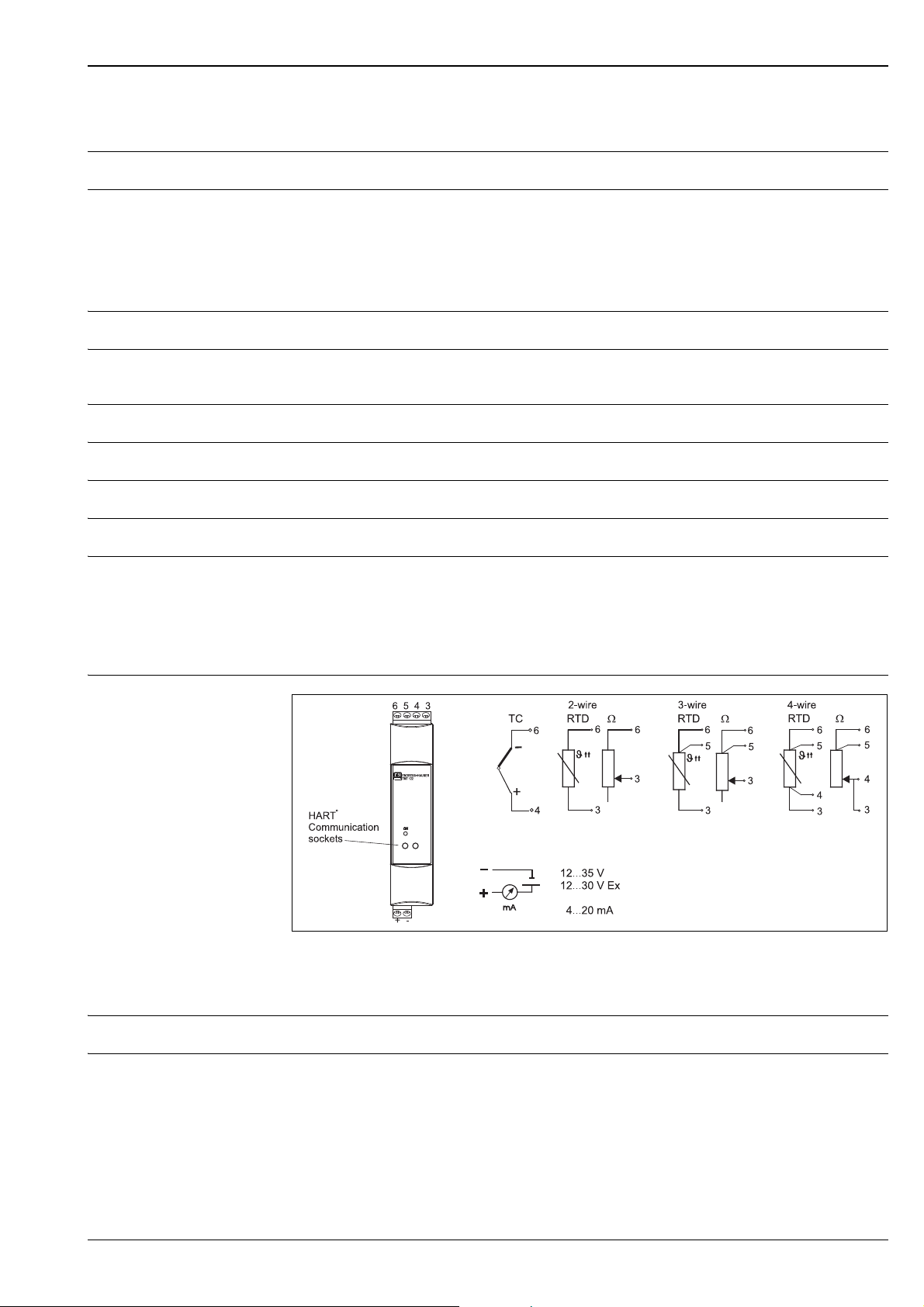
Electrical connection
T09-TMT122-04-10-XX-en-001
Temperature transmitter terminal connections
For the unit operation via HART® communication sockets a minimum load resistance of 250 is
necessary in the signal circuit!
Supply voltage Ub = 12 to 35 V, polarity protected
dual ripple Allowable ripple Uss 3 V at Ub 15 V, f
Resi
max.
= 1 kHz
Endress+Hauser 3
Page 4
Performance characteristics
Response time 1 s
TMT122
Reference operating conditions
Maximum measured error
Calibration temperature: +25 °C ± 5 K (77 °F ± 9 °F)
The accuracy data are typical values and correspond to a standard deviation of ± 3 (normal
distribution), i.e. 99.8% of all the measured values achieve the given values or better values.
Type Measurement accuracy
Resistance thermometer RTD Pt100, Ni100
Pt500, Ni500
Pt1000, Ni1000
Thermocouple TC K, J, T, E, L, U
N, C, D
R, S
B
Measurement range Measurement accuracy
Resistance transmitter (
Voltage transmitter (mV) -10 to 75 mV ± 20 V or 0.08%
1. % is related to the adjusted measurement range. The value to be applied is the greater.
) 10 to 400
10 to 2000
0.2 K or 0.08%
0.5 K or 0.20%
0.3 K or 0.12%
typ. 0.5 K or 0.08%
typ. 1.0 K or 0.08%
typ. 1.4 K or 0.08%
typ. 2.0 K or 0.08%
± 0.1 or 0.08%
± 1.5 or 0.12%
1
1
Physical input range of the sensors
10 to 400 Polynom RTD, Pt100, Ni100
10 to 2000 Pt500, Pt1000, Ni1000
-10 to 75 mV Thermocouple type: C, D, E, J, K, L, N, U
-10 to 35 mV Thermocouple type: B, R, S, T
Influence of power supply ± 0.01%/V deviation from 24 V
Percentages refer to the full scale value.
Influence of ambient tempe-
Total temperature drift = input temperature drift + output temperature drift
rature (temperature drift)
Effect on the accuracy when ambient temperature changes by 1 K (1.8 °F):
Input 10 to 400 typ. 0.0015% of measured value, min. 4 m
Input 10 to 2000 typ. 0.0015% of measured value, min. 20 m
Input -10 to 75 mV typ. 0.005% of measured value, min. 1.2 μV
Input -10 to 35 mV typ. 0.005% of measured value, min. 0.6 μV
Output 4 to 20 mA typ. 0.005% of span
Typical sensitivity of resistance thermometers:
Pt: 0.00385 * R
Example Pt100: 0.00385 x 100 /K = 0.385 /K
/K Ni: 0.00617 * R
nominal
nominal
/K
4 Endress+Hauser
Page 5

TMT122
Typical sensitivity of thermocouples:
B: 10 μV/K C: 20 μV/K D: 20 μV/K E: 75 μV/K J: 55 μV/K K: 40 μV/K
L: 55 μV/K N: 35 μV/K R: 12 μV/K S: 12 μV/K T: 50 μV/K U: 60 μV/K
Example for calculating measured error for ambient temperature drift:
Input temperature drift = 10 K (18 °F), Pt100, measuring range 0 to 100 °C (32 to 212 °F)
Maximum process temperature: 100 °C (212 °F)
Measured resistance value: 138.5 (IEC 60751) at maximum process temperature
Typical temperature drift in : (0.0015% of 138.5 ) * 10 = 0.02078
Conversion to Kelvin: 0.02078 / 0.385 /K = 0.05 K (0.09 °F)
Influence of load ±0.02%/100
Values refer to the full scale value
Long term stability 0.1K/year or 0.05%/year
Values under reference operating conditions. % refer to the set span. The highest value is valid.
Influence of cold junction Pt100 DIN IEC 60751 Cl. B (internal reference junction for thermocouples TC)
Installation conditions
Installation instructions Orientation
No limit
Environment conditions
Ambient temperature limits 40 to +85 °C (-40 to +185 °F) for Ex-area, see Ex-certificate
Storage temperature -40 to +100 °C (-40 to +212 °F)
Climate class According to IEC 60654-1, Class C
Condensation Permitted
Degree of protection IP 20 (NEMA 1)
Shock and vibration resistance
Electromagnetic compatibility (EMC)
4g / 2 to 150 Hz as per IEC 60 068-2-6
CE conformity
EMC to all relevant requirements of the IEC/EN 61326 - series and NAMUR Recommendation EMC
(NE21). For details, refer to the Declaration of Conformity.
Maximum fluctuations during EMC- tests: < 1% of measuring span.
Interference immunity to IEC/EN 61326 - series, requirements for industrial areas
Interference emission to IEC/EN 61326 - series, electrical equipment Class B
Endress+Hauser 5
Page 6
Mechanical construction
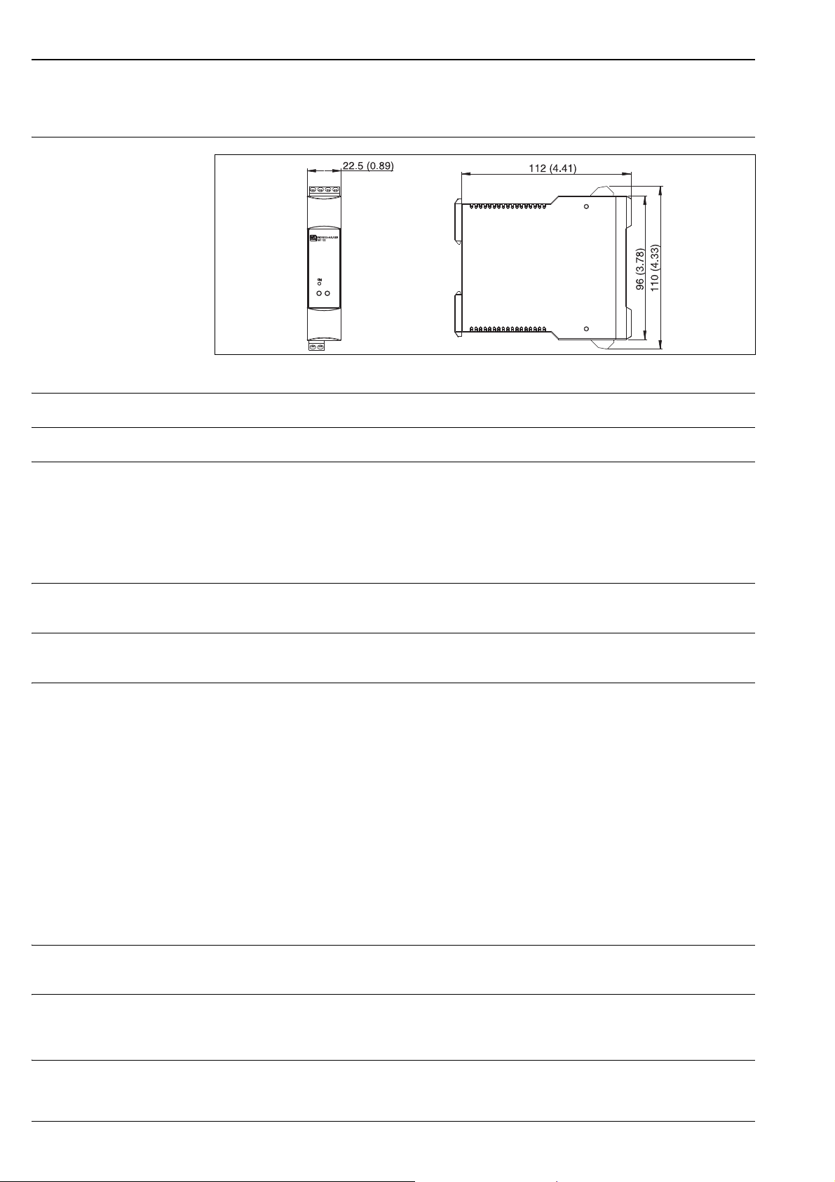
Design, dimensions
Housing for DIN rail mounting according to IEC 60715; Dimensions in mm (in)
Weight Approx. 90 g (3.2 oz)
Material Housing: Plastic PC/ABS, UL 94V0
TMT122
T09-TMT122-06-10-XX-en-002
Terminals • Keyed plug-in screw terminals, core size max. 2.5 mm² (16 AWG) solid, or strands with ferrules
• Front mounted HART
®
communication socket for 2 mm jack plugs
Human interface
Display elements A yellow illuminated LED signalizes: Device is operational.
With the PC software ReadWin® 2000 or FieldCare the current measured value can be displayed.
Operating elements At the temperature transmitter no operating elements are available directly. The temperature trans-
mitter will be configured by remote operation with the PC software ReadWin
Remote operation Configuration
Hand operating module DXR375 or PC with Commubox FXA191/FXA195 and operating software
(ReadWin
Interface
PC interface Commubox FXA191 (RS232) or FXA195 (USB).
Configurable parameters
Sensor type and connection type, engineering units (°C/°F), measurement range, internal/external cold
junction compensation, cable resistance compensation on 2-wire connection, fault conditioning, output signal (4 to 20/20 to 4 mA), digital filter (damping), offset, measurement point identification +
descriptor (8 + 16 characters), output simulation, customer specific linearisation, min./max. process
value indicator function.
®
2000 or FieldCare).
®
2000 or FieldCare.
Certificates and approvals
CE-Mark The device meets the legal requirements of the EC directives. Endress+Hauser confirms that the device
has been successfully tested by applying the CE mark.
Hazardous area approvals For further details on the available Ex versions (ATEX, CSA, FM, etc.), please contact your nearest End-
ress+Hauser sales organisation. All relevant data for hazardous areas can be found in separate Ex
documentation. If required, please request copies from us or your Endress+Hauser sales organisation.
Marine approval For further details on the available "Type Approval Certificiates" (DNVGL, BV, etc.), please contact your
nearest Endress+Hauser sales organisation. All relevant data for marine approval can be found in
6 Endress+Hauser
Page 7

TMT122
separate "Type Approval Certificiates". If required, please request copies from us or your
Endress+Hauser sales organisation.
UL approval UL recognized component (see www.ul.com/database, search for Keyword "E225237")
Other standards and guidelines
CSA GP CSA General Purpose
IEC 60529:
Degree of protection provided by housing (IP-Code)
IEC 61010:
Safety requirements for electrical measurement, control and laboratory use.
IEC 61326:
Electromagnetic compatibility (EMC requirements)
NAMUR
Standards working group for measurement and control technology in the chemical industry.
(www.namur.de)
Ordering information
Detailed ordering information is available from the following sources:
• In the Product Configurator on the Endress+Hauser website: www.endress.com -> Click "Corporate"
-> Select your country -> Click "Products" -> Select the product using the filters and search field ->
Open product page -> The "Configure" button to the right of the product image opens the Product
Configurator.
• From your Endress+Hauser Sales Center: www.addresses.endress.com
•
Product Configurator - the tool for individual product configuration
• Up-to-the configuration
• Depending on the device: Direct input of measuring point-specific information such as
measuring range or operating language
• Automatic verification of exclusion criteria
• Automatic creation of the order code and its breakdown in PDF or Excel output format
• Ability to order directly in the Endress+Hauser Online Shop
Accessories
• Commubox FXA191 (RS232) or FXA195 (USB)
Order code: FXA191-... or FXA195-...
• PC-operating software: ReadWin
ReadWin® 2000 can be downloaded free of charge from the internet from the following address:
www.endress.com/readwin
• Hand operating module ’HART® Communicator DXR375’, Order code: DXR375-...
®
2000 or FieldCare
Documentation
• Compact instructions ’iTEMP HART® DIN rail TMT122’ (KA128R/09/a3)
• Additional documentation for use in explosion-hazardous areas:
ATEX II2(1)G (XA016R/09/a3)
ATEX II3G (XA019R/09/a3)
Endress+Hauser 7
Page 8

TMT112
www.addresses.endress.com
 Loading...