

Endress+Hauser Micropilot M FMR231, Micropilot M FMR244, Micropilot M FMR240, Micropilot M FMR230 Operating Instructions Manual
BA226F/00/en/08.06
5200
9947
Valid as of software version:
01.04.00
Operating Instructions
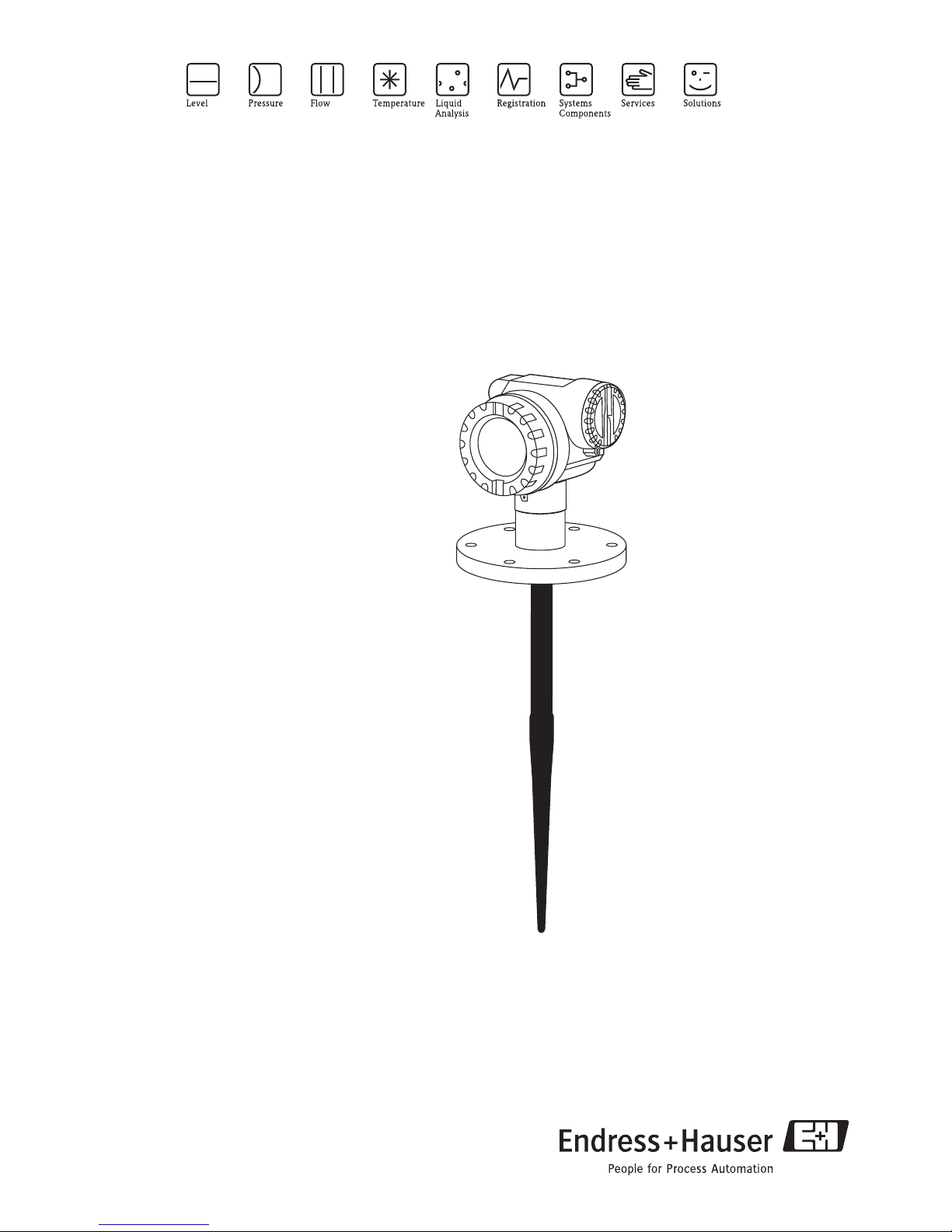
Micropilot M FMR231
Level-Radar
8
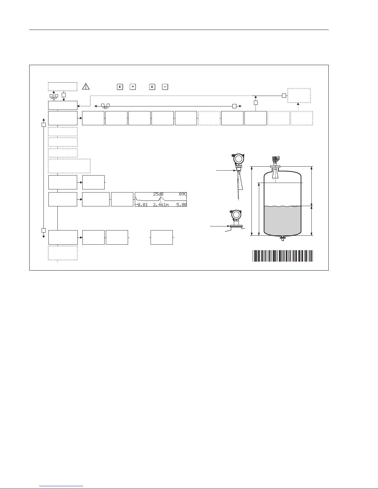
Brief operating instructions Micropilot M FMR231 with PROFIBUS PA
2 Endress+Hauser
Brief operating instructions
L00-FMR2xxxx-19-00-00-en-039
!
Note!
This operating manual explains the installation and initial start-up for the level transmitter. All
functions that are required for a typical measuring task are taken into account here. In addition, the
Micropilot M provides many other functions that are not included in this operating manual, such as
optimising the measuring point and converting the measured values.
An overview of all device functions can be found on Page 98.
The operating manual BA 221F/00/en "Description of the instrument functions for Micropilot M"
provides an extensive description of all device functions, which can be found on the enclosed
CD-ROM.
E
+
-
+
E
+
-
F
L
D
E
E
E
-
… …
… …
KA159F/00/a2/08.06
52006292
52006292
… …
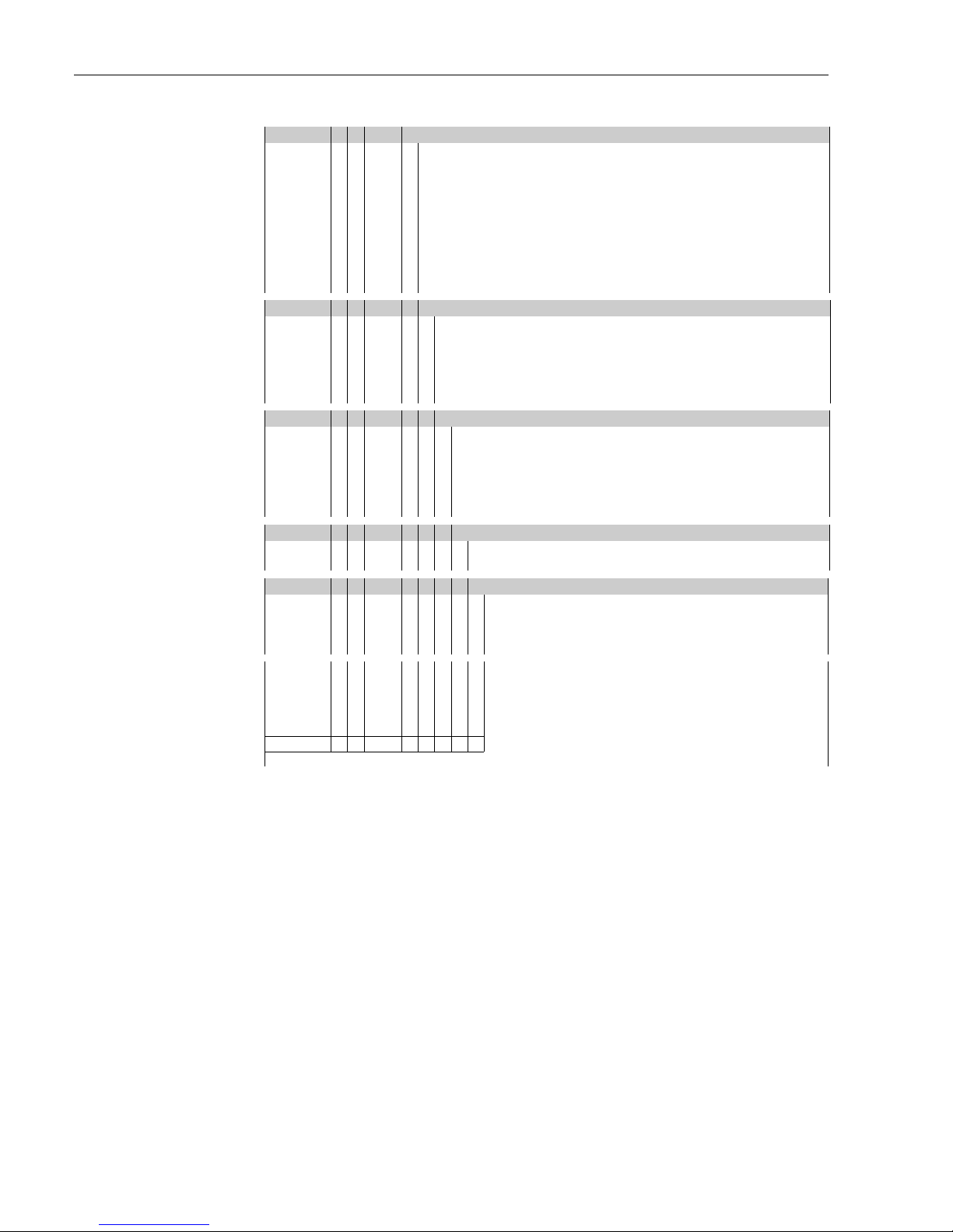
Micropilot M FMR230, FMR231 - Brief operating instructions
- dome
ceiling
- horizontal
cyl.
- bypass
…
- unknown
- DC: <1.9
- DC: 1.9 … 4
-DC:4…10
- DC: >10
- standard
- calm
surface
- add. agitator
…
input E
(see sketch)
input F
(see sketch)
only for
bypass +
stilling well
-ok
- too small
- too big
- unknown
- manual
displayed
(see sketch)
D and L are
confirm
or specify
range
suggestion
000
measured value
Group
selection
00
basic setup
01
safety settings
0C
system
parameter
09
display
0E
envelope curve
04
linearisation
05
extended calibr.
06
output (HART, FF)
profibus param.(PA)
092
language
0A
diagnostics
0A0
present
error
002
tank shape
004
process
cond.
005
empty
calibr.
006
full
calibr.
007
pipe
diameter
008
dist./
meas value
051
check
distance
003
medium
cond.
052
range of
mapping
053
start
mapping
008
dist./
meas value
flange:
reference point
of measurement
- envel. curve
- incl. FAC
- incl. cust. map
- single curve
- cyclic
= 100: unlocked
100: locked
= 2457: unlocked
2457: locked
0E1
plot settings
0E2
recording
curve
0A1
previous
error
0A4
unlock
parameter
threaded connection:
reference point of
measurement
HART
PA, FF
}
}
Contrast: + or +

Micropilot M FMR231 with PROFIBUS PA Table of contents
Endress+Hauser 3
Table of contents
1 Safety instructions . . . . . . . . . . . . . . . . 4
1.1 Designated use . . . . . . . . . . . . . . . . . . . . . . . . . . . . 4
1.2 Installation, commissioning and operation . . . . . . . . 4
1.3 Operational safety . . . . . . . . . . . . . . . . . . . . . . . . . . 4
1.4 Notes on safety conventions and symbols . . . . . . . . . 5
2 Identification . . . . . . . . . . . . . . . . . . . . 6
2.1 Device designation . . . . . . . . . . . . . . . . . . . . . . . . . 6
2.2 Scope of delivery . . . . . . . . . . . . . . . . . . . . . . . . . . . 9
2.3 Certificates and approvals . . . . . . . . . . . . . . . . . . . . 9
2.4 Registered trademarks . . . . . . . . . . . . . . . . . . . . . . . 9
3 Mounting . . . . . . . . . . . . . . . . . . . . . . 10
3.1 Quick installation guide . . . . . . . . . . . . . . . . . . . . . 10
3.2 Incoming acceptance, transport, storage . . . . . . . . . 11
3.3 Installation conditions . . . . . . . . . . . . . . . . . . . . . . 12
3.4 Installation instructions . . . . . . . . . . . . . . . . . . . . . 20
3.5 Post-installation check . . . . . . . . . . . . . . . . . . . . . . 22
4 Wiring . . . . . . . . . . . . . . . . . . . . . . . . 23
4.1 Quick wiring guide . . . . . . . . . . . . . . . . . . . . . . . . 23
4.2 Connecting the measuring unit . . . . . . . . . . . . . . . 26
4.3 Recommended connection . . . . . . . . . . . . . . . . . . 27
4.4 Degree of protection . . . . . . . . . . . . . . . . . . . . . . . 27
4.5 Post-connection check . . . . . . . . . . . . . . . . . . . . . . 27
5 Operation . . . . . . . . . . . . . . . . . . . . . . 28
5.1 Quick operation guide . . . . . . . . . . . . . . . . . . . . . . 28
5.2 Display and operating elements . . . . . . . . . . . . . . . 30
5.3 Local operation . . . . . . . . . . . . . . . . . . . . . . . . . . . 33
5.4 Display and acknowledging error messages . . . . . . 36
5.5 PROFIBUS PA communication . . . . . . . . . . . . . . . . 37
6 Commissioning. . . . . . . . . . . . . . . . . . 53
6.1 Function check . . . . . . . . . . . . . . . . . . . . . . . . . . . 53
6.2 Switching on the measuring device . . . . . . . . . . . . 53
6.3 Basic Setup . . . . . . . . . . . . . . . . . . . . . . . . . . . . . . 54
6.4 Basic Setup with the VU 331 . . . . . . . . . . . . . . . . . 56
6.5 Basic Setup with the Endress+Hauser oprating
program . . . . . . . . . . . . . . . . . . . . . . . . . . . . . . . . 68
7 Maintenance. . . . . . . . . . . . . . . . . . . . 72
8 Accessories. . . . . . . . . . . . . . . . . . . . . 73
9 Trouble-shooting . . . . . . . . . . . . . . . . 76
9.1 Trouble-shooting instructions . . . . . . . . . . . . . . . . 76
9.2 System error messages . . . . . . . . . . . . . . . . . . . . . . 77
9.3 Application errors . . . . . . . . . . . . . . . . . . . . . . . . . 79
9.4 Orientation of the Micropilot . . . . . . . . . . . . . . . . . 81
9.5 Spare parts . . . . . . . . . . . . . . . . . . . . . . . . . . . . . . 83
9.6 Return . . . . . . . . . . . . . . . . . . . . . . . . . . . . . . . . . . 90
9.7 Disposal . . . . . . . . . . . . . . . . . . . . . . . . . . . . . . . . . 90
9.8 Software history . . . . . . . . . . . . . . . . . . . . . . . . . . . 90
9.9 Contact addresses of Endress+Hauser . . . . . . . . . . . 90
10 Technical data . . . . . . . . . . . . . . . . . . . 91
10.1 Additional technical data . . . . . . . . . . . . . . . . . . . . 91
11 Appendix. . . . . . . . . . . . . . . . . . . . . . . 98
11.1 Operating menu PA (display modul), ToF Tool . . . . 98
11.2 Description of functions . . . . . . . . . . . . . . . . . . . . 100
11.3 Function and system design . . . . . . . . . . . . . . . . . 101
Index . . . . . . . . . . . . . . . . . . . . . . . . . . . . . 104

Safety instructions Micropilot M FMR231 with PROFIBUS PA
4 Endress+Hauser
1 Safety instructions
1.1 Designated use
The Micropilot M FMR 231 is a compact radar level transmitter for the continuous, contactless
measurement of liquids, pastes and sludge. The device can also be freely mounted outside closed
metal vessels because of its operating frequency of about 6 GHz and a maximum radiated pulsed
energy of 1mW (average power output 1 µW). Operation is completely harmless to humans and
animals.
1.2 Installation, commissioning and operation
The Micropilot M has been designed to operate safely in accordance with current technical, safety
and EU standards. If installed incorrectly or used for applications for which it is not intended,
however, it is possible that application-related dangers may arise, e.g. product overflow due to
incorrect installation or calibration. For this reason, the instrument must be installed, connected,
operated and maintained according to the instructions in this manual: personnel must be authorised
and suitably qualified. The manual must have been read and understood, and the instructions
followed. Modifications and repairs to the device are permissible only when they are expressly
approved in the manual.
1.3 Operational safety
1.3.1 Hazardous areas
Measuring systems for use in hazardous environments are accompanied by separate "Ex
documentation", which is an integral part of this Operating Manual. Strict compliance with the
installation instructions and ratings as stated in this supplementary documentation is mandatory.
• Ensure that all personnel are suitably qualified.
• Observe the specifications in the certificate as well as national and local standards and regulations.
1.3.2 FCC approval
This device complies with part 15 of the FCC Rules. Operation is subject to the following two
conditions: (1) This device may not cause harmful interference, and (2) this device must accept any
interference received, including interference that may cause
undesired operation.
"
Caution!
Changes or modifications not expressly approved by the part responsible for
compliance could void the user’s authority to operate the equipment.

Micropilot M FMR231 with PROFIBUS PA Safety instructions
Endress+Hauser 5
1.4 Notes on safety conventions and symbols
In order to highlight safety-relevant or alternative operating procedures in the manual, the following
conventions have been used, each indicated by a corresponding symbol in the margin.
Safety conventions
#
Warning!
A warning highlights actions or procedures which, if not performed correctly, will lead to personal
injury, a safety hazard or destruction of the instrument
"
Caution!
Caution highlights actions or procedures which, if not performed correctly, may lead to personal
injury or incorrect functioning of the instrument
!
Note!
A note highlights actions or procedures which, if not performed correctly, may indirectly affect
operation or may lead to an instrument response which is not planned
Explosion protection
0
Device certified for use in explosion hazardous area
If the device has this symbol embossed on its name plate it can be installed in an explosion hazardous
area
-
Explosion hazardous area
Symbol used in drawings to indicate explosion hazardous areas. Devices located in and wiring
entering areas with the designation “explosion hazardous areas” must conform with the stated type
of protection.
.
Safe area (non-explosion hazardous area)
Symbol used in drawings to indicate, if necessary, non-explosion hazardous areas. Devices located in
safe areas still require a certificate if their outputs run into explosion hazardous areas
Electrical symbols
%
Direct voltage
A terminal to which or from which a direct current or voltage may be applied or supplied
&
Alternating voltage
A terminal to which or from which an alternating (sine-wave) current or voltage may be applied or
supplied
)
Grounded terminal
A grounded terminal, which as far as the operator is concerned, is already grounded by means of an
earth grounding system
*
Protective grounding (earth) terminal
A terminal which must be connected to earth ground prior to making any other connection to the
equipment
+
Equipotential connection (earth bonding)
A connection made to the plant grounding system which may be of type e.g. neutral star or
equipotential line according to national or company practice
Temperature resistance of the connection cables
States, that the connection cables must be resistant to a temperature of at least 85 °C.
t >85°C
Identification Micropilot M FMR231 with PROFIBUS PA
6 Endress+Hauser
2 Identification
2.1 Device designation
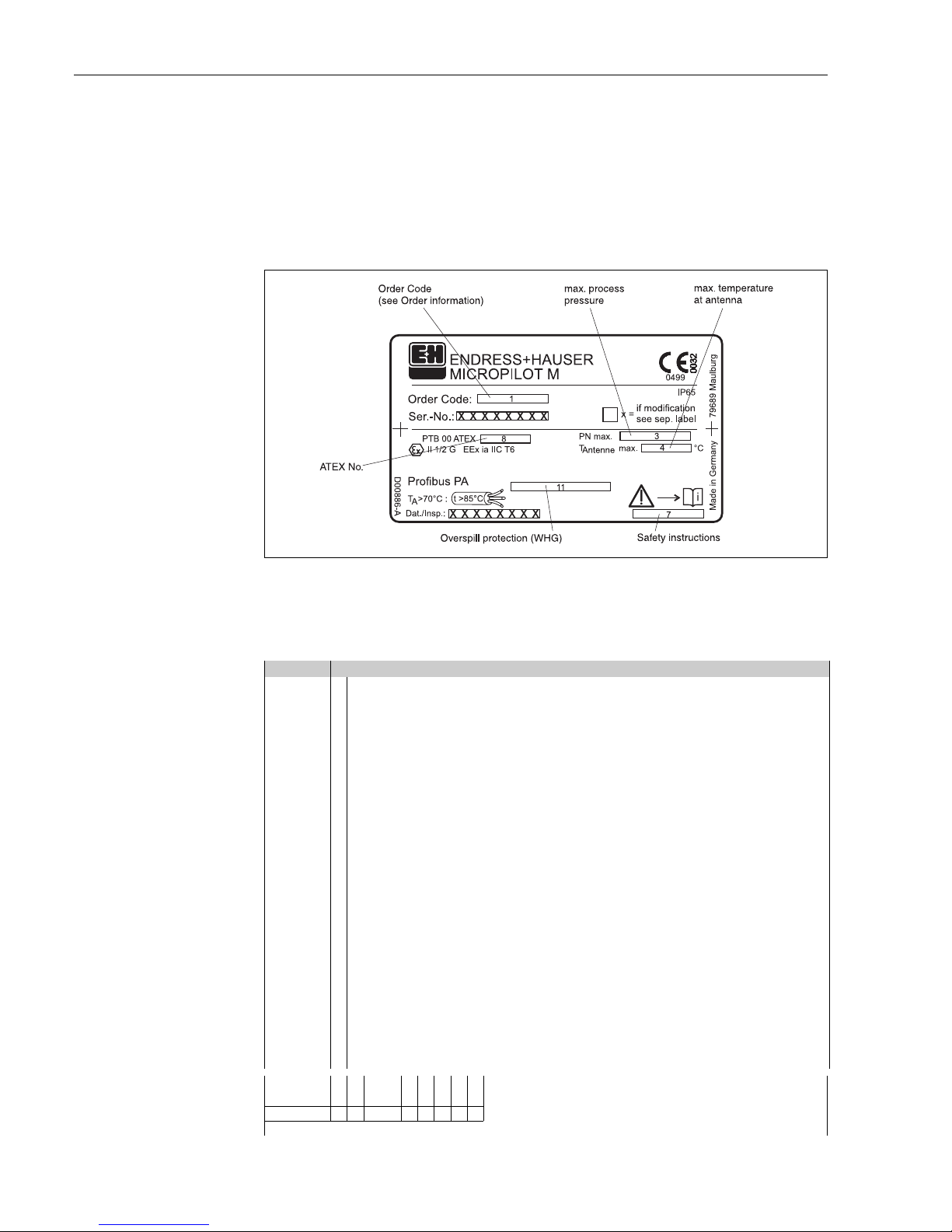
2.1.1 Nameplate
The following technical data are given on the instrument nameplate:
L00-FMR2xxxx-18-00-00-en-002
Fig. 1: Information on the nameplate of the Micropilot M with PROFIBUS PA (example)
2.1.2 Ordering structure
Ordering structure Micropilot M FMR 231
10 Approval:
A Non-hazardous area
F Non-hazardous area, WHG
1 ATEX II 1/2 G EEx ia IIC T6, IECEx Zone 0/1
2 ATEX II 1/2 G EEx ia IIC T6, XA, IECEx Zone 0/1
Note safety instruction (XA) (electrostatic charging)!
6 ATEX II 1/2 G EEx ia IIC T6, WHG, IECEx Zone 0/1
7 ATEX II 1/2 G EEx ia IIC T6, WHG, XA, IECEx Zone 0/1
Note safety instruction (XA) (electrostatic charging)!
3 ATEX II 1/2 G EEx em [ia] IIC T6, IECEx Zone 0/1
8 ATEX II 1/2 G EEx em [ia] IIC T6, WHG, IECEx Zone 0/1
4 ATEX II 1/2 G EEx d [ia] IIC T, IECEx Zone 0/16
G ATEX II 3 G EEx nA II T6, XA,
fully insutalted antenna: Note safety instruction (XA) (electrostatic charging)!
H ATEX II 1/2G EEx ia IIC T6, ATEX II 3D, XA,
fully insutalted antenna: Note safety instruction (XA) (electrostatic charging)!
S FM IS - Cl.I Div.1 Gr. A-D
T FM XP - Cl.I Div.1 Group A-D
N CSA General Purpose
U CSA IS - Cl.I Div.1 Group A-D
V CSA XP - Cl.I Div.1 Group A-D
K TIIS EEx ia IIC T4
L TIIS EEx d [ia] IIC T4
M TIIS EEx d [ia] IIC T1
I NEPSI Ex ia IIC T6
J NEPSI Ex d [ia] IIC T6
R NEPSI Ex nAL IIC T6
Y Special version
FMR 231- Product designation (part 2)
Micropilot M FMR231 with PROFIBUS PA Identification
Endress+Hauser 7
Ordering structure Micropilot M FMR 231 (continued)
20 Antenna; Inactive length:
A PPS antistatic 360mm/14", Viton, 316L; nozzle height max 100mm/4"
B PPS antistatic 510mm/20", Viton, 316L; nozzle height max 250mm/10"
E PTFE 390mm/15", fully insulated; nozzle height max 100mm/4"
F PTFE 540mm/21", fully insulated; nozzle height max 250mm/10"
H PTFE antistatic 390mm/15", fully insul.; nozzle height max 100mm/4"
J PTFE antistatic 540mm/21", fully insul.; nozzle height max 250mm/10"
Y Special version
30 Process connection:
GGJ 1½" BSPT (R 1½")
GGS 1½" BSPT (R 1½")
GNJ NPT 1½"
GNS NPT 1½"
TEJ Tri-Clamp ISO2852 DN40-51 (2"), 316L
TLJ Tri-Clamp ISO2852 DN70-76.1 (3"), 316L
MFJ DIN11851 DN50 PN40, 316L
HFJ DIN11864-1 A DN50 Tube DIN11850, 316L
BFJ DN50 PN10/16 A, 316L flange EN1092-1 (DIN2527 B)
CFJ DN50 PN10/16 B1, 316L flange EN1092-1 (DIN2527 C)
CFK DN50 PN10/16, PTFE>316L flange EN1092-1 (DIN2527)
BMJ DN80 PN10/16 A, 316L flange EN1092-1 (DIN2527 B)
CMJ DN80 PN10/16 B1, 316L flange EN1092-1 (DIN2527 C)
BNJ DN80 PN25/40 A, 316L flange EN1092-1 (DIN2527 B)
CNJ DN80 PN25/40 B1, 316L flange EN1092-1 (DIN2527 C)
CMK DN80 PN10/16, PTFE>316L flange EN1092-1 (DIN2527)
BQJ DN100 PN10/16 A, 316L flange EN1092-1 (DIN2527 B)
CQJ DN100 PN10/16 B1, 316L flange EN1092-1 (DIN2527 C)
CQK DN100 PN10/16, PTFE>316L flange EN1092-1 (DIN2527)
BWJ DN150 PN10/16 A, 316L flange EN1092-1 (DIN2527 B)
CWJ DN150 PN10/16 B1, 316L flange EN1092-1 (DIN2527 C)
CWK DN150 PN10/16, PTFE(black)>316L flange EN1092-1 (DIN2527)
PTFE(black) = conductive cladding
AEJ 2" 150lbs RF, 316/316L flange ANSI B16.5
AEK 2" 150lbs, PTFE>316/316L flange ANSI B16.5
ALJ 3" 150lbs RF, 316/316L flange ANSI B16.5
AMJ 3" 300lbs RF, 316/316L flange ANSI B16.5
ALK 3" 150lbs, PTFE>316/316L flange ANSI B16.5
APJ 4" 150lbs RF, 316/316L flange ANSI B16.5
AQJ 4" 300lbs RF, 316/316L flange ANSI B16.5
APK 4" 150lbs, PTFE>316/316L flange ANSI B16.5
AVJ 6" 150lbs RF, 316/316L flange ANSI B16.5
AVK 6" 150lbs, PTFE(black)>316/316L flange ANSI B16.5
PTFE(black) = conductive cladding
KEJ 10K 50A RF, 316L flange JIS B2220
KEK 10K 50A, PTFE>316L flange JIS B2220
KLJ 10K 80A RF, 316L flange JIS B2220
KLK 10K 80A, PTFE>316L flange JIS B2220
KPJ 10K 100A RF, 316L flange JIS B2220
KPK 10K 100A, PTFE>316L flange JIS B2220
KVJ 10K 150A RF, 316L flange JIS B2220
KVK 10K 150A, PTFE(black)>316L flange JIS B2220
PTFE(black) = conductive cladding
YY9 Special version
FMR 231- Product designation (part 1)
Identification Micropilot M FMR231 with PROFIBUS PA
8 Endress+Hauser
Ordering structure Micropilot M FMR 231 (continued)
40 Output; Operation:
A 4-20mA SIL HART; 4-line display VU331, envelope curve display on site
B 4-20mA SIL HART; w/o display, via communication
K 4-20mA SIL HART; Prepared for FHX40, remote display (Accessory)
C PROFIBUS PA; 4-line display VU331, envelope curve display on site
D PROFIBUS PA; w/o display, via communication
L PROFIBUS PA; Prepared for FHX40, remote display (Accessory)
E FOUNDATION Fieldbus; 4-line display VU331, envelope curve display on site
F FOUNDATION Fieldbus; w/o display, via communication
M FOUNDATION Fieldbus; Prepared for FHX40, remote display (Accessory)
Y Special version
50 Housing:
A F12 Alu, coated IP65 NEMA4X
B F23 316L IP65 NEMA4X
C T12 Alu, coated IP65 NEMA4X, separate conn. compartment
D T12 Alu, coated IP65 NEMA4X+OVP, separate conn. compartment,
OVP=overvoltage protection
Y Special version
60 Cable entry:
2 Gland M20 (EEx d > thread M20)
3Thread G1/2
4 Thread NPT1/2
5Plug M12
6 Plug 7/8"
9Special version
70 Gas-tight feed through:
ANot selected
C Selected
80 Additional option:
A Basic version
B EN10204-3.1B (316L wetted parts) Inspection certificate
S GL/ABS/NK marine certificate
Y Special version
FMR 231- Complete product designation

Micropilot M FMR231 with PROFIBUS PA Identification
Endress+Hauser 9
2.2 Scope of delivery
"
Caution!
It is essential to follow the instructions concerning the unpacking, transport and storage of
measuring instruments given in the chapter "Incoming acceptance, transport, storage" on Page 11!
The scope of delivery consists of:
• Assembled instrument
• Endress+Hauser oprating program (on the enclosed CD-ROM
• Accessories (→ Chap. 8)
Accompanying documentation:
• Short manual (basic setup/troubleshooting): housed in the instrument
• Operating manual (this manual)
• Approval documentation: if this is not included in the operating manual.
!
Note!
The operating manual "Description of Instrument Functions" you can be found on the enclosed CDROM.
2.3 Certificates and approvals
CE mark, declaration of conformity
The device is designed to meet state-of-the-art safety requirements, has been tested and left the
factory in a condition in which it is safe to operate. The device complies with the applicable
standards and regulations as listed in the EC declaration of conformity and thus complies with the
statutory requirements of the EG directives. Endress+Hauser confirms the successful testing of the
device by affixing to it the CE mark.
2.4 Registered trademarks
KALREZ®, VITON®, TEFLON
®
Registered trademark of the company, E.I. Du Pont de Nemours & Co., Wilmington, USA
TRI-CLAMP
®
Registered trademark of the company, Ladish & Co., Inc., Kenosha, USA
ToF
®
Registered trademark of the company Endress+Hauser GmbH+Co. KG, Maulburg, Germany
PulseMaster
®
Registered trademark of the company Endress+Hauser GmbH+Co. KG, Maulburg, Germany
PhaseMaster
®
Registered trademark of the company Endress+Hauser GmbH+Co. KG, Maulburg, Germany
PROFIBUS
®
Registered trademark of the PROFIBUS Trade Organisation, Karlsruhe, Germany
Mounting Micropilot M FMR231 with PROFIBUS PA
10 Endress+Hauser
3Mounting
3.1 Quick installation guide
L00-FMR231xx-17-00-00-en-003
1
1
2
2
#
90°
90°
90°
90°
90°
90°
90°
90°
90°
90°
9
DN50
ANSI 2”
DN80…150
ANSI 3…6”
F12/F23 housing
T12 housing
Turn housing
Observe orientation when installing!
Installation in tank (free space):
Mark on process connector facing the nearest tank wall!
The housing can be turned 350°
in order to simplify access to the
display and the terminal compartment
Allen key
4 mm
1½” BSPT (R 1½”)
or
1½ NPT
mark at instrument flange
or threaded boss

Micropilot M FMR231 with PROFIBUS PA Mounting
Endress+Hauser 11
3.2 Incoming acceptance, transport, storage
3.2.1 Incoming acceptance
Check the packing and contents for any signs of damage.
Check the shipment, make sure nothing is missing and that the scope of supply matches your order.
3.2.2 Transport
"
Caution!
Follow the safety instructions and transport conditions for instruments of more than
18 kg.
Do not lift the measuring instrument by its housing in order to transport it.
3.2.3 Storage
Pack the measuring instrument so that is protected against impacts for storage and transport. The
original packing material provides the optimum protection for this.
The permissible storage temperature is -40 °C…+80 °C.
Mounting Micropilot M FMR231 with PROFIBUS PA
12 Endress+Hauser
3.3 Installation conditions
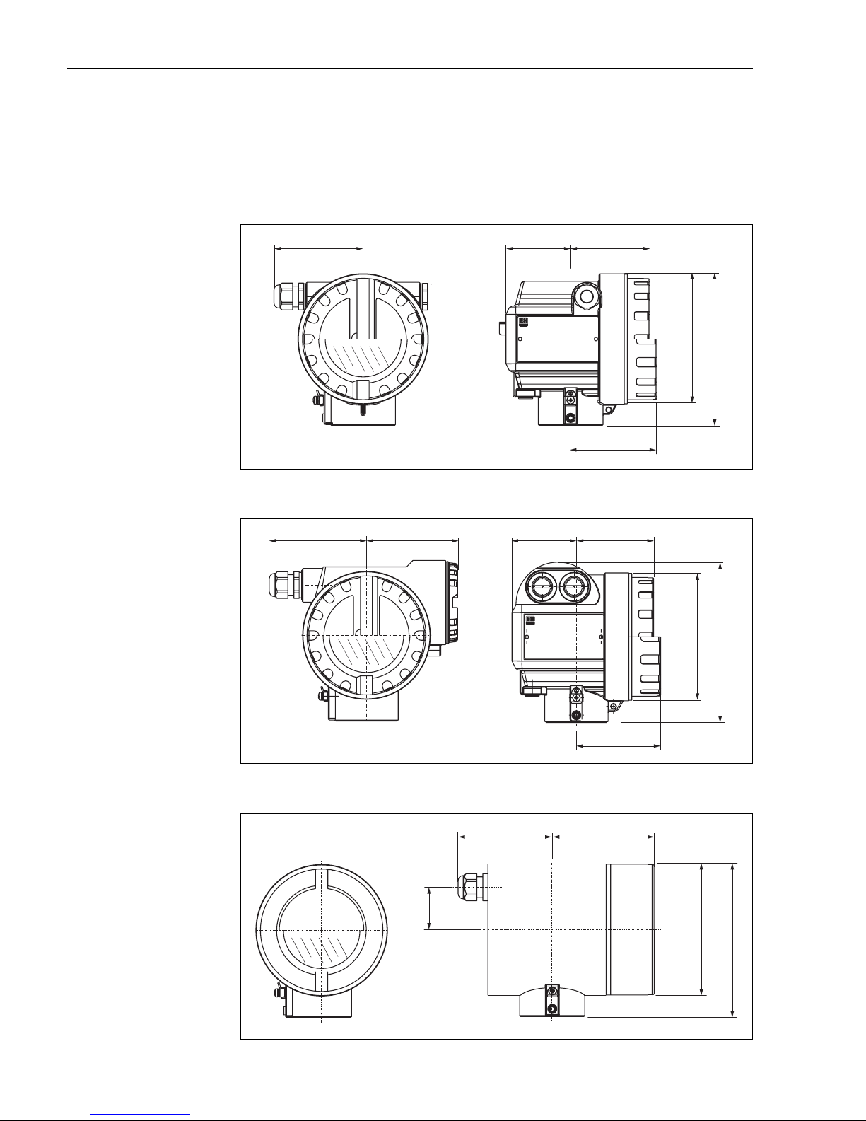
3.3.1 Dimensions
Housing dimensions
L00-F12xxxx-06-00-00-en-001
L00-T12xxxx-06-00-00-en-001
L00-F23xxxx-06-00-00-en-001
ENDRESS+HAUSER
65
78
max. 110
85
150
Ø 129
(Aluminium)
F12 housing
ENDRESS+HAUSER
78
85
65
162
max. 100 94
Ø 129
(Aluminium)
T12 housing
max. 94
104
Ø 129
150
40
(316L)
F23 housing
Micropilot M FMR231 with PROFIBUS PA Mounting
Endress+Hauser 13
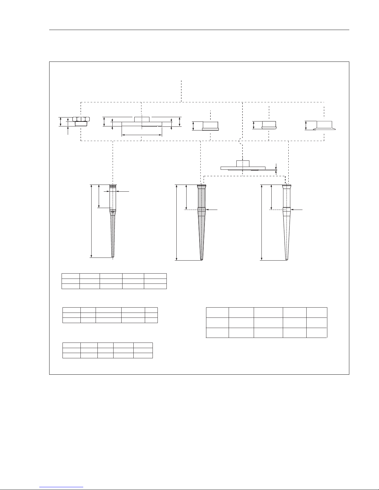
Micropilot M FMR 231 - process connection, type of antenna
L00-FMR231xx-06-00-00-en-005
a
a
L2
390 / 540
Ø 33
a
Ø 25
Ø D
L2
360 / 510
L2
390 / 540
Ø 33
43
b
b
23
a
a
41
77
44.5
80.5
41
77
41
77
b [mm]
DN 80DN 50
20 (24)20
200 (200)165
D [mm]
220
20
DN 100
285
22
DN 150
b [mm]
b [mm]
DN 80
3”
DN 50
2”
18
23.9 (28.4)
16
19.1
185
190.5 (209.5)
155
152.4
D [mm]
D [mm]
210
228.6 (254)
18
23.9 (31.8)
DN 100
4”
280
279.4
22
25.4
DN 150
6”
4
Threaded connection
1½” (R
or 1 ½ NPT
BSPT 1 ½”)
Flange DN 50…150
or equivalent
PPS, antistatic
PTFE, antistatic
Flange
cladded version
DN 50 dairy coupling
DIN 11851
2”/3” Tri-Clamp
ISO 2852
a [mm]
without gastight
feedthrough
a [mm]
with gastight
feedthrough
Flange
DN 50…150
DN 50 aseptic
coupling
DN 50 diary
coupling
2”/3”
Tri-Clamp
Process
connection
Inactive length, equivalent
to max. nozzle height
L2 = 100 mm / 250 mm
for PN 16 (for PN 40)
Flange
Flange to EN 1092-1 (agreeable to DIN 2527)
PTFE
(in conjunction with
)
DN50 aseptic/dairy coupling
respectively Tri-clamp
FDA-listed TFM 1600
for 10K
Flange
Flange to JIS B2220
for 150 lbs (for 300 lbs)
Flange
Flange to ANSI B16.5
DN 50 aseptic
DIN 11864-1 form A
with O-ring for tubes
according to DIN 11850
F12 / T12 / F23 housing
Mounting Micropilot M FMR231 with PROFIBUS PA
14 Endress+Hauser
3.3.2 Engineering hints
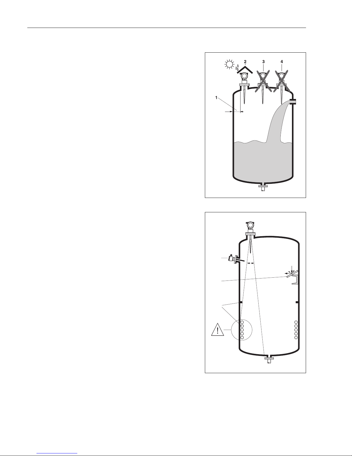
Orientation
• Recommended distance (1) wall – outer
edge of nozzle: ~1/6 of tank diameter.
Nevertheless the device should not be
installed closer than 30 cm (12“) to the
tankwall.
• Not in the centre (3), interference can cause
signal loss.
• Not above the fill stream (4).
• It is recommended to use a weather
protection cover (2) in order to protect the
transmitter from direct sun or rain. Assembly
and disassembly is simply done by means of a
tension clamp (→ Chap. 8 on Page 73).
L00-FMR2xxxx-17-00-00-xx-006
Tank installations
• Avoid any installations (1), like limit switches,
temperature sensors, etc., inside the signal
beam (refer to beam angle see "Beam angle"
on Page 16).
• Symmetrical installations (2), i.e. vacuum
rings, heating coils, baffles, etc., can also
interfere with the measurement.
Optimization options
• Antenna size: the bigger the antenna, the
smaller the beam angle, the less interference
echoes.
• Mapping: the measurement can be optimized
by means of electronic suppression of
interference echoes.
• Antenna alignment: refer to "optimum
mounting position"
• Stilling well: a stilling well can always be used
to avoid interference.
• Metallic screens (3) mounted at a slope spread
the radar signals and can, therefore, reduce
interference echoes.
Please contact Endress+Hauser for further information.
L00-FMR2xxxx-17-00-00-xx-007
1
3
2
a
Micropilot M FMR231 with PROFIBUS PA Mounting
Endress+Hauser 15
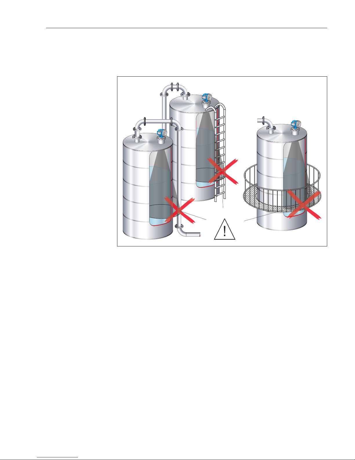
Measurement in a plastic tank
If the outer wall of the tank is made of a non-conductive material (e.g. GRP), microwaves can also
be reflected off interfering installations outside the signal beam (e.g. metallic pipes (1), ladders (2),
grates (3), …). Therefore, there should be no such interfering installations in the signal beam.
L00-FMR2xxxx-17-00-00-xx-013
Please contact Endress+Hauser for further information.
VH
00
VH
00
Endress+Hauser
Endress+Hauser
-
+
V
H
ENDRESS+HA
USER
MICROPILOT II
IP 65
O
rd
e
r
C
o
d
e
:
Se
r
.-N
o
.:
M
e
ssbereich
M
e
a
sur
in
g r
a
nge
U
16...3
6
V D
C
4
...
20
m
A
m
ax
.
2
0 m
Made in Germany Maulburg
Made in Germany Maulburg
T>
7
0
°C
:
A
t
>
8
5
°
C
VH
00
VH
00
Endress+Hauser
Endress+Hauser
-
+
V
H
ENDRESS+HA
USER
MICROPILOT II
IP 65
O
rd
er
C
od
e
:
S
e
r
.-N
o
.:
M
e
ssbereich
M
ea
sur
in
g r
ange
U
16...3
6
V D
C
4
...
2
0
m
A
m
ax.
2
0 m
Made in Germany Maulburg
Made in Germany Maulburg
T>
7
0
°
C
:
A
t
>
8
5
°
C
VH
00
VH
00
Endress+Hauser
Endress+Hauser
-
+
V
H
ENDRESS+HA
USER
MICROPILOT II
IP 65
O
rd
e
r
C
o
d
e
:
Se
r
.-N
o
.:
M
essb
e
re
ich
M
easu
r
in
g r
an
ge
U
1
6
...36
V
D
C
4
...2
0
m
A
m
ax.
20
m
Made in Germany Maulburg
Made in Germany Maulburg
T>
7
0
°
C
:
A
t
>
8
5
°
C
1
2
3
Mounting Micropilot M FMR231 with PROFIBUS PA
16 Endress+Hauser
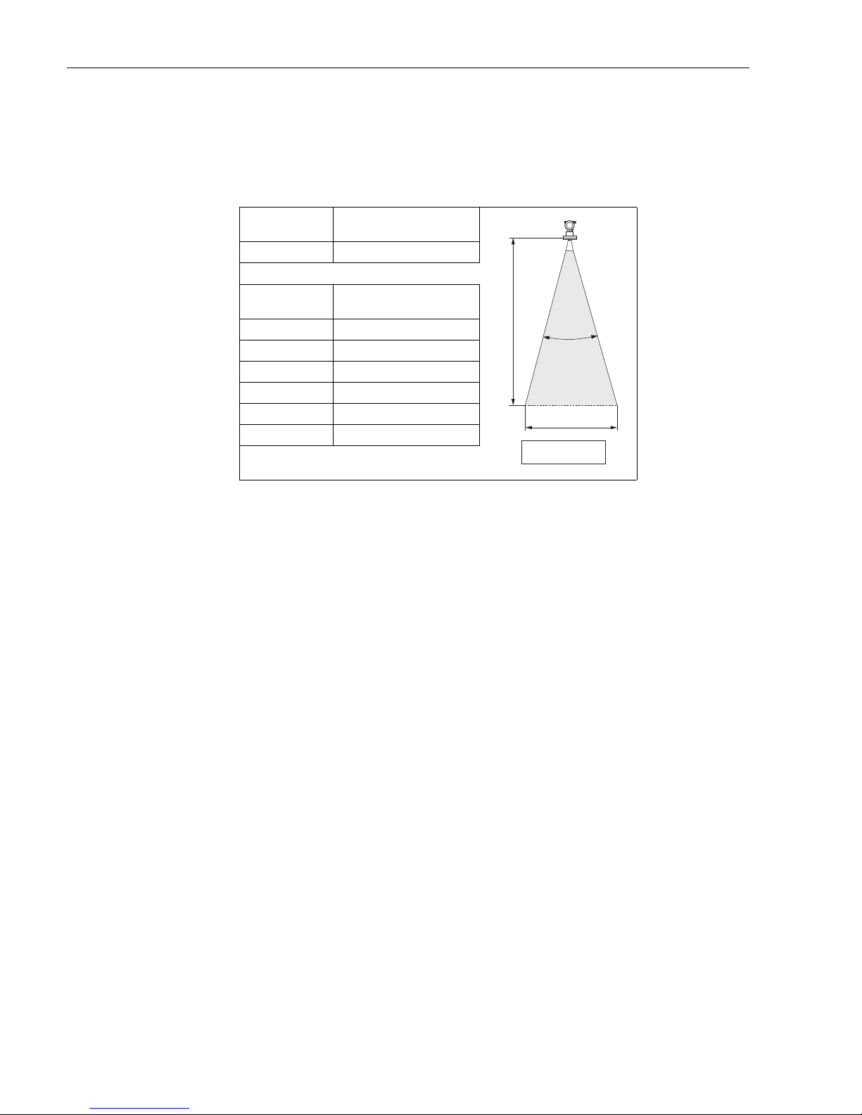
Beam angle
The beam angle is defined as the angle a where the energy density of the radar waves reaches half
the value of the maximum energy density (3dB-width). Microwaves are also emitted outside the
signal beam and can be reflected off interfering installations. Beam diameter W as function of
antenna type (beam angle α) and measuring distance D:
Antenna
FMR 231
Rod
L00-FMR2xxxx-14-00-06-de-027
Beam angle α 30°
Measuring dis-
tance (D)
Beam diameter (W)
Rod
3 m (10 ft) 1.61 m (5.36 ft)
6 m (20 ft) 3.22 m (10.72 ft)
9 m (30 ft) 4.82 m (16.08 ft)
12 m (40 ft) 6.43 m (21.44 ft)
15 m (49 ft) 8.04 m (26.26 ft)
20 m (65 ft) 10.72 m (34.83 ft)
a
D
W
a
D
_
=
2
2
..
tan
W
Micropilot M FMR231 with PROFIBUS PA Mounting
Endress+Hauser 17
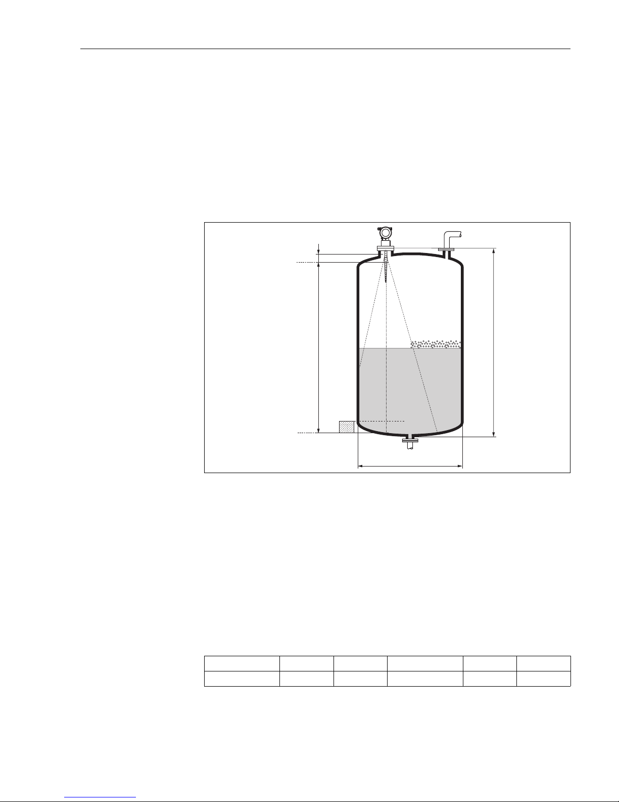
Measuring conditions
L00-FMR2xxxx-17-00-00-de-017
• The measuring range begins, where the beam hits the tank bottom. Particularly with dish bottoms
or conical outlets the level cannot be detected below this point.
• In case of media with a low dielectric constant (groups A and B), the tank bottom can be visible
through the medium at low levels (low height C). Reduced accuracy has to be expected in this
range. If this is not acceptable, we recommend positioning the zero point at a distance C (see Fig.)
above the tank bottom in these applications.
• In principle it is possible to measure up to the tip of the antenna with FMR230/231/240.
However, due to considerations regarding corrosion and build-up, the end of the measuring range
should not be chosen any closer than A (see Fig.) to the tip of the antenna.
For FMR244/245, the end of measuring range should not be chosen closer than A (see Fig.) to
the tip of the antenna, especially if there is development of condensate.
• The smallest possible measuring range B depends on the antenna version (see Fig.).
• The tank diameter should be greater than D (see Fig.), the tank height at least H (see Fig.).
Note!
• In case of boiling surfaces, bubbling or tendency for foaming, use FMR230 or FMR231.
Depending on its consistence, foam can either absorb microwaves or reflect them off the foam
surface. Measurement is possible under certain conditions.
• In case of heavy steam development or condensate the max. measuring range of FMR240 may
decrease depending on density, temperature and composition of the steam → use FMR230 or
FMR231.
• For the measurement of absorbing gases such as ammonia NH
3
or some fluorocarbons
1))
,
please use FMR230 in a stilling well.
1) Affected compounds are e.g. R134a, R227, Dymel 152a.
100%
0%
B
A
C
H
ØD
A [mm/inch] B [m/inch] C [mm/inch] D [m/inch] H [m/inch]
FMR231 50 / 2 > 0,5 / > 20 150...300 / 6...12 > 1 / > 40 > 1,5 / > 60

Mounting Micropilot M FMR231 with PROFIBUS PA
18 Endress+Hauser
Measuring range
The usable measuring range depends on the size of the antenna, the reflectivity of the medium, the
mounting location and eventual interference reflections.
The maximum configurable range is:
• 20 m (65 ft) for Micropilot M FMR23x,
• 20 m (65 ft) for Micropilot M FMR24x,
– 40 m (131 ft) for Micropilot M FMR24x with additional option D (E), see "ordering
information",
– 70 M (229 ft) for Micropilot M FMR24x with additional option F (G), see "ordering
information",
• 70 m (229 ft) for Micropilot M FMR250 (further informations see TI390F/00/en).
The following tables describe the groups of media as well as the achievable measuring range as a
function of application and media group. If the dielectric constant of a medium is unknown, it is
recommended to assume media group B to ensure a reliable measurement.
Media group DC (εr) Examples
A 1,4...1,9 non-conducting liquids, e.g. liquefied gas
1))
1) Treat Ammonia NH3 as a medium of group A, i.e. use FMR230 in a stilling well.
B 1,9...4 non-conducting liquids, e.g. benzene, oil, toluene, …
C 4...10 e.g. concentrated acids, organic solvents, esters, aniline, alcohol, acetone, …
D > 10 conducting liquids, e.g. aqueous solutions, dilute acids and alkalis
Micropilot M FMR231 with PROFIBUS PA Mounting
Endress+Hauser 19
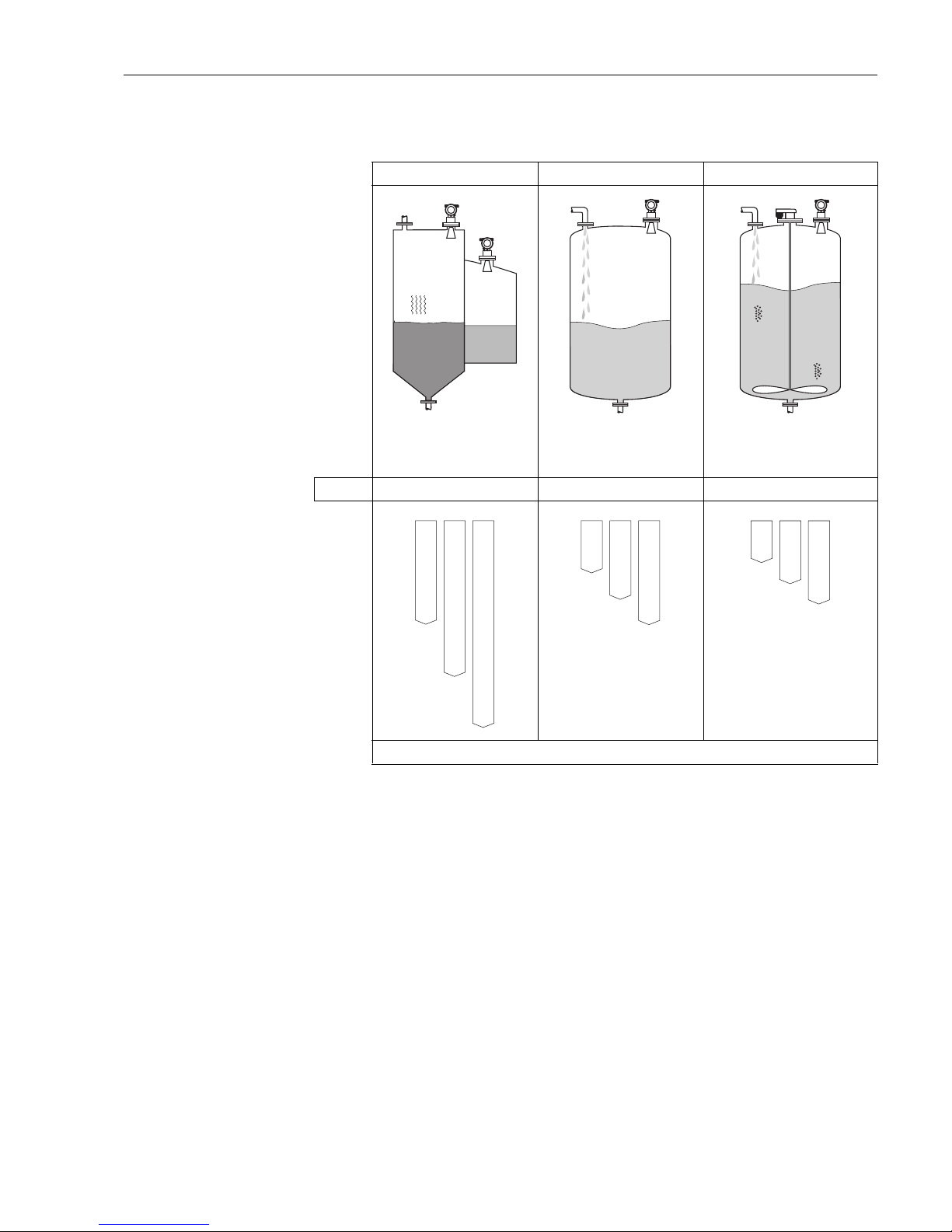
Measuring range depending on vessel type, conditions and product for
Micropilot M FMR231
Storage tank
1)
Buffer tank
1)
Process tank with agitator
1)
Calm product surface
(e.g. intermittent filling, filling
from bottom, immersion tubes).
Moving surfaces (e.g. continuous
filling, from above, mixing jets).
Turbulent surface.
Single stage agitator < 60 U/min.
FMR231: Rod antenna Rod antenna Rod antenna
Measuring range [m (ft)]
1) For media group A to use a stilling well (20 m / 65 ft).
BB
10
(33)
20
(65)
15
(49)
CCDD
BB
10
(33)
7.5
(24)
5
(16)
CCDD
BB
8
(27)
4
(13)
6
(20)
CCDD
Mounting Micropilot M FMR231 with PROFIBUS PA
20 Endress+Hauser
3.4 Installation instructions
3.4.1 Mounting kit
In addition to the tool needed for flange mounting, you will require the following tool:
• 4 mm/0.1" Allen wrench for turning the housing.
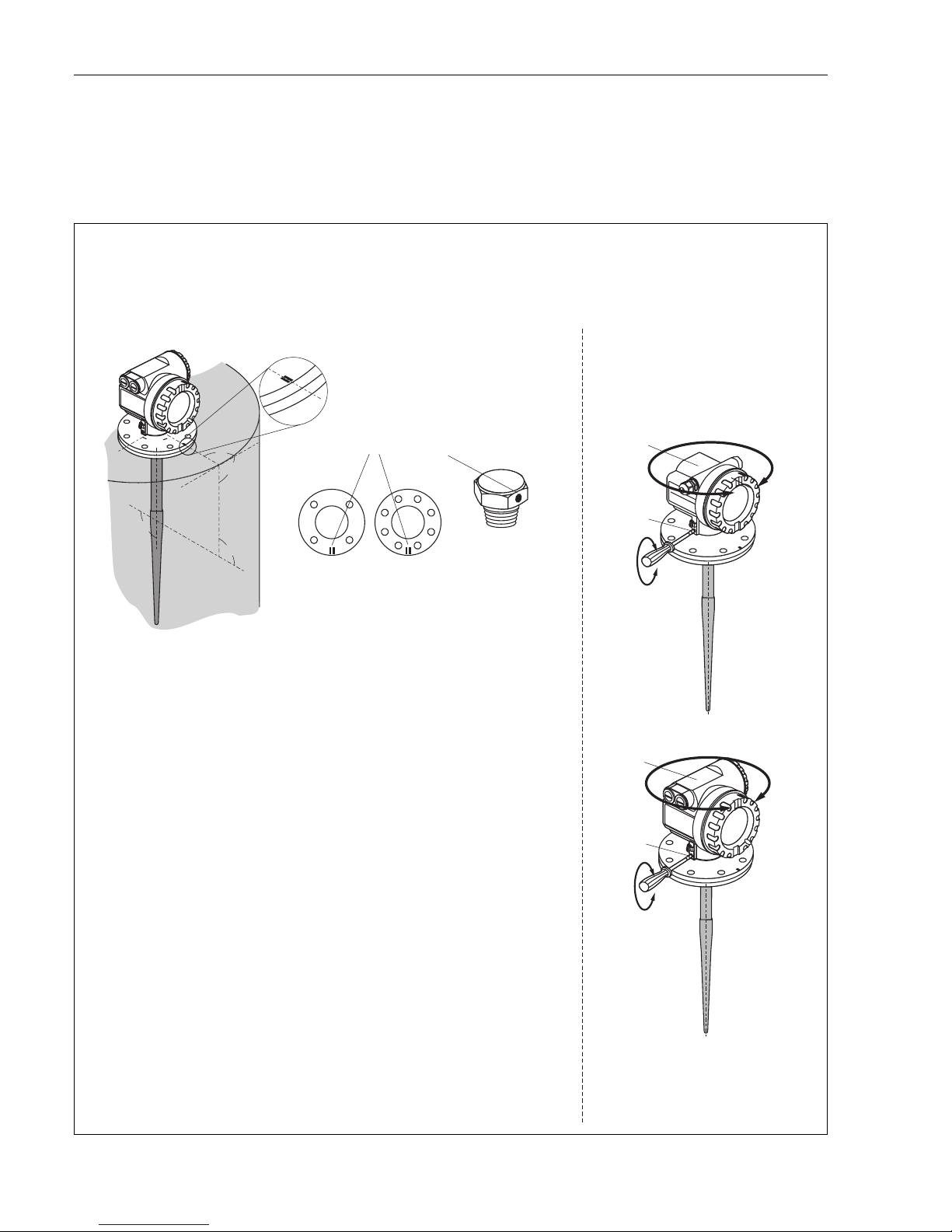
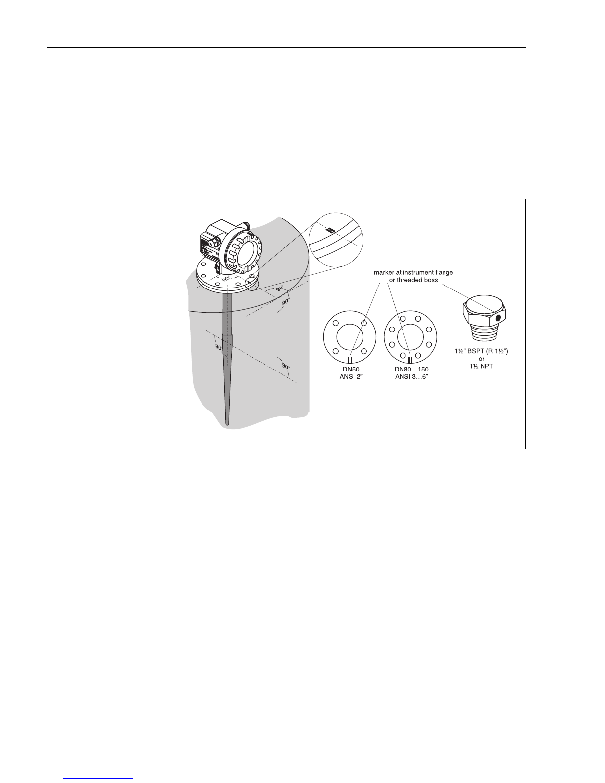
3.4.2 Installation in tank (free space)
Optimum mounting position
L00-FMR231xx-17-00-00-en-001
Standard installation
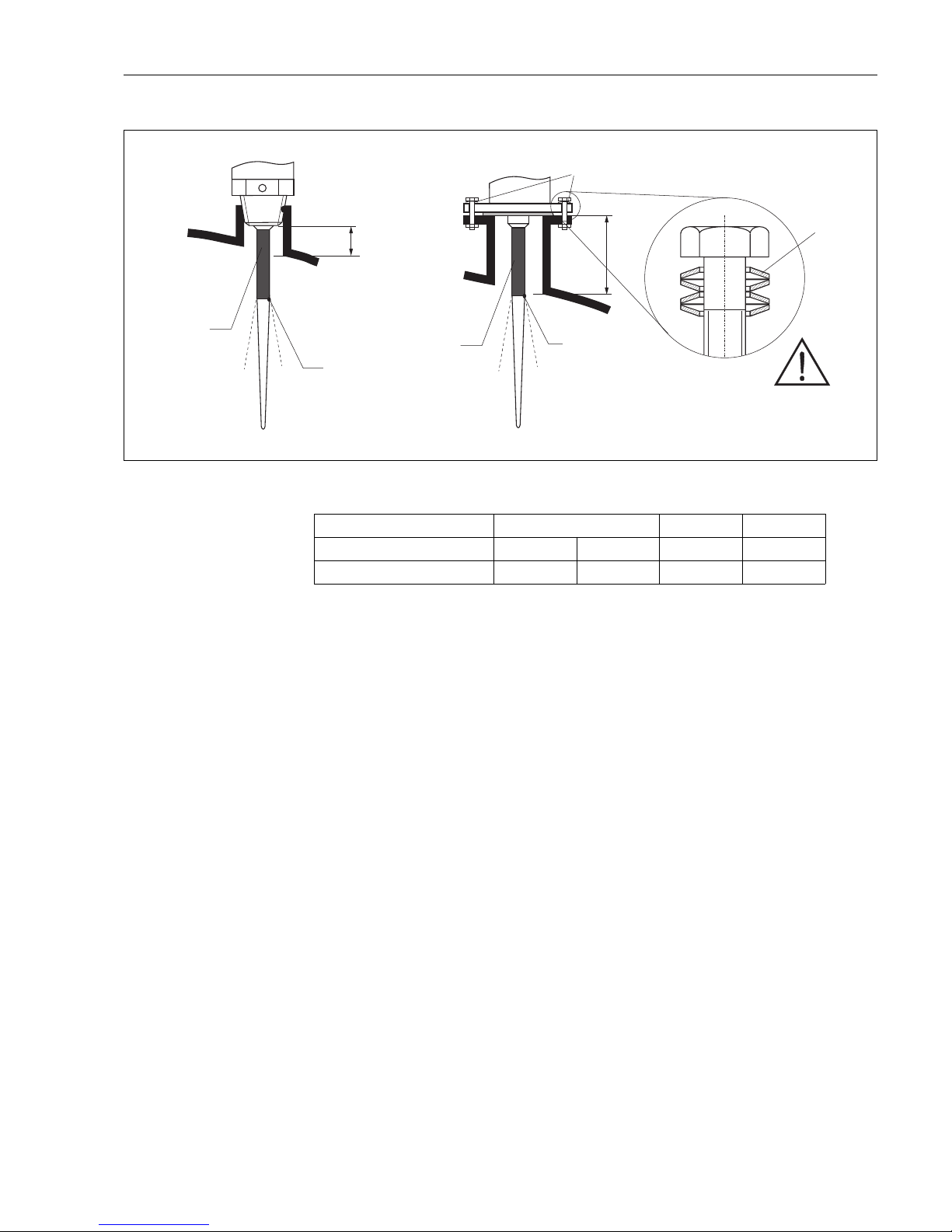
For installations in a stilling well, follow the engineering hints on Page 14 and note the following
points:
• Marker is aligned towards tank wall.
• The marker is always exactly in the middle between two bolt-holes in the flange.
• Use spring washers (1) (see Fig.).
Note!
It is recommended to retighten the flange bolts periodically, depending on process temperature
and pressure. Recommended torque: 60...100 Nm.
• After mounting, the housing can be turned 350° in order to simplify access to the display and the
terminal compartment.
• The inactive part of the rod antenna must extend below the nozzle.
• The rod antenna must be aligned vertically.
Micropilot M FMR231 with PROFIBUS PA Mounting
Endress+Hauser 21
L00-FMR231xx-17-00-00-en-002
H
H
1
beam launched
here
beam launched
here
inactive length
inactive length
spring washers
Material PPS PTFE
Antenna length [mm / inch] 360 / 14 510 / 20 390 / 15 540 / 21
H [mm/inch] < 100 / < 4 < 250 / < 10 < 100 / < 4 < 250 / < 10
Mounting Micropilot M FMR231 with PROFIBUS PA
22 Endress+Hauser
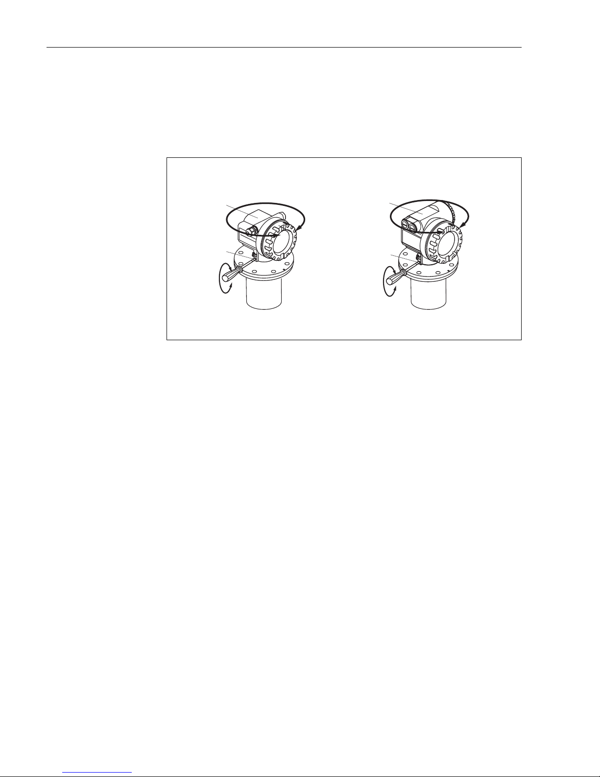
3.4.3 Turn housing
After mounting, the housing can be turned 350° in order to simplify access to the display and the
terminal compartment. Proceed as follows to turn the housing to the required position:
• Undo the fixing screws (1)
• Turn the housing (2) in the required direction
• Tighten up the fixing screws (1)
L00-FMR2xxxx-17-00-00-en-010
3.5 Post-installation check
After the measuring instrument has been installed, perform the following checks:
• Is the measuring instrument damaged (visual check)?
• Does the measuring instrument correspond to the measuring point specifications such as process
temperature/pressure, ambient temperature, measuring range, etc.?
• Is the flange marking correctly aligned? (→ Page 10)
• Have the flange screws been tightened up with the respective tightening torque?
• Are the measuring point number and labeling correct (visual check)?
• Is the measuring instrument adequately protected against rain and direct sunlight (→ Page 73)?
1
1
2
2
F12 / F23 housing T12 housing
allen key
4 mm/0.1”
Micropilot M FMR231 with PROFIBUS PA Wiring
Endress+Hauser 23
4 Wiring
4.1 Quick wiring guide
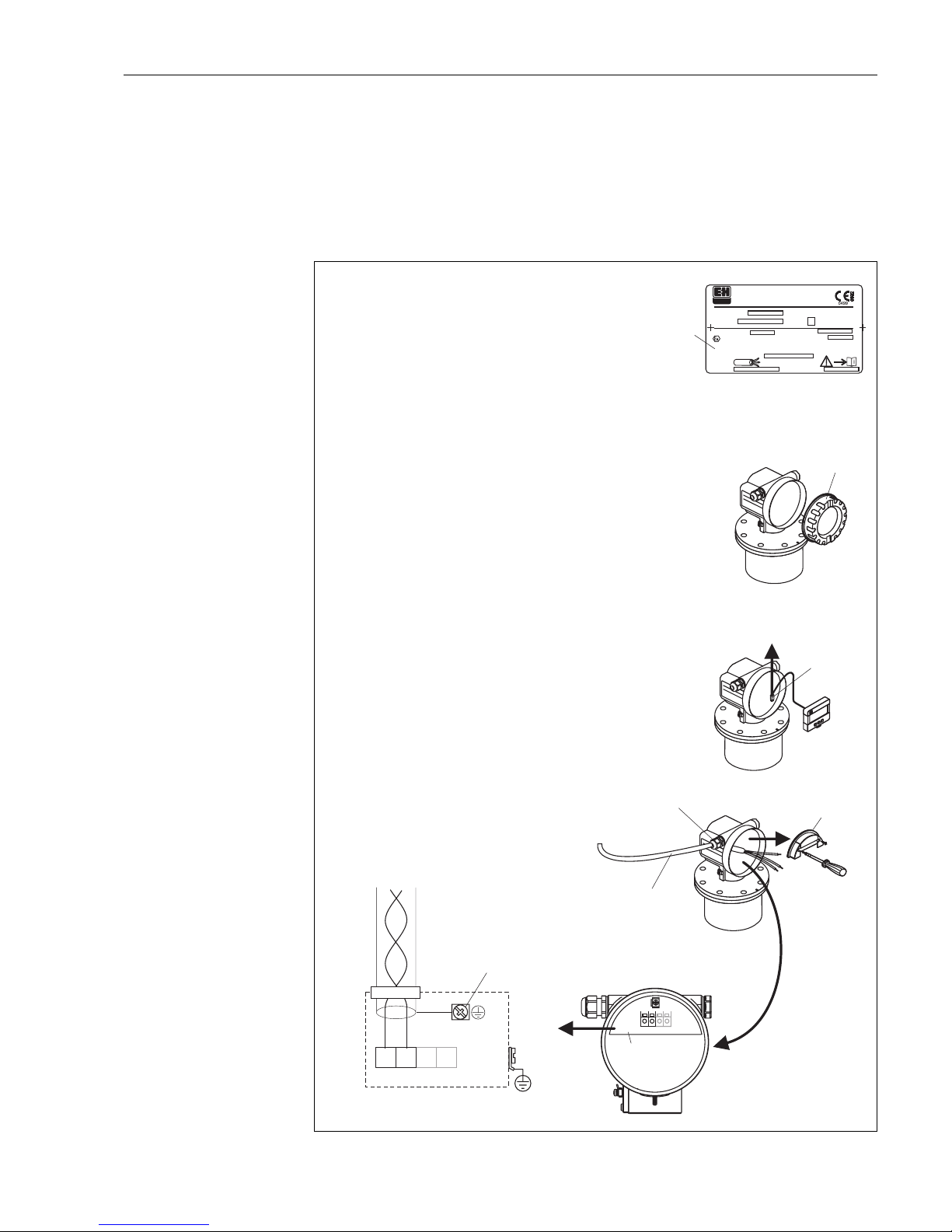
Wiring in F12/F23 housing
L00-FMR2xxxx-04-00-00-en-016
1
-
-
"
Ser.-No.:
Order Code:
D00886-A
t >85°C
x=
if modification
see sep. label
Dat./Insp.:
PN max.
T
Antenne
max. °C
79689 Maulburg
Made in Germany
T >70°C :
A
MICROPILOT M
ENDRESS+HAUSER
Profibus PA
PTB 00ATEX
II 1/2 G EEx ia IIC T6
IP65
xxxxxxxx
xxxxxxxx
1
3
4
11
8
7
7
EN
D
RESS+H
A
USER
ENDRESS+HAUSER
#
4
5
6
2
3
1234
3
4
1
2
+–
Sealed terminal
compartment
Before connection please note the following:
PROFIBUS devices are marked on the nameplate (1).The
voltage is determined by the PROFIBUS standard and the
desired safety concept. (see chapter 4.3).
Connect potential matching line to transmitter earth terminal
before connecting up the device.
Tighten the locking screw:
It forms the connection between the antenna and the housing
earth potential.
l
l
l
When you use the measuring system in hazardous areas, make sure you comply with
national standards and the specifications in the safety instructions (XA’s).
Make sure you use the specific cable gland.
On devices supplied with a certificate, the explosion protection
is designed as follows:
Housing F12/F23 - EEx ia:
Power supply must be intrinsically safe.
The electronics and the current output are galvanically
separated from the antenna circuit.
l
l
Connect up the Micropilot M as follows:
Unscrew housing cover (2).
Remove any display (3) if fitted.
Remove cover plate from terminal compartment (4).
Pull out terminal module slightly using pulling loop.
Insert cable (5) through gland (6).
Use screened, twisted wire pair.
Only earth screen conductor (7) on sensor side.
Make connection (see pin assignment).
Re-insert terminal module.
Tighten cable gland (6).
Tighten screws on cover plate (4).
Insert display if fitted.
Screw on housing cover (2).
l
l
l
l
l
l
l
l
l
l
l
Unplug display connector!
Caution!
plant
ground
Wiring Micropilot M FMR231 with PROFIBUS PA
24 Endress+Hauser
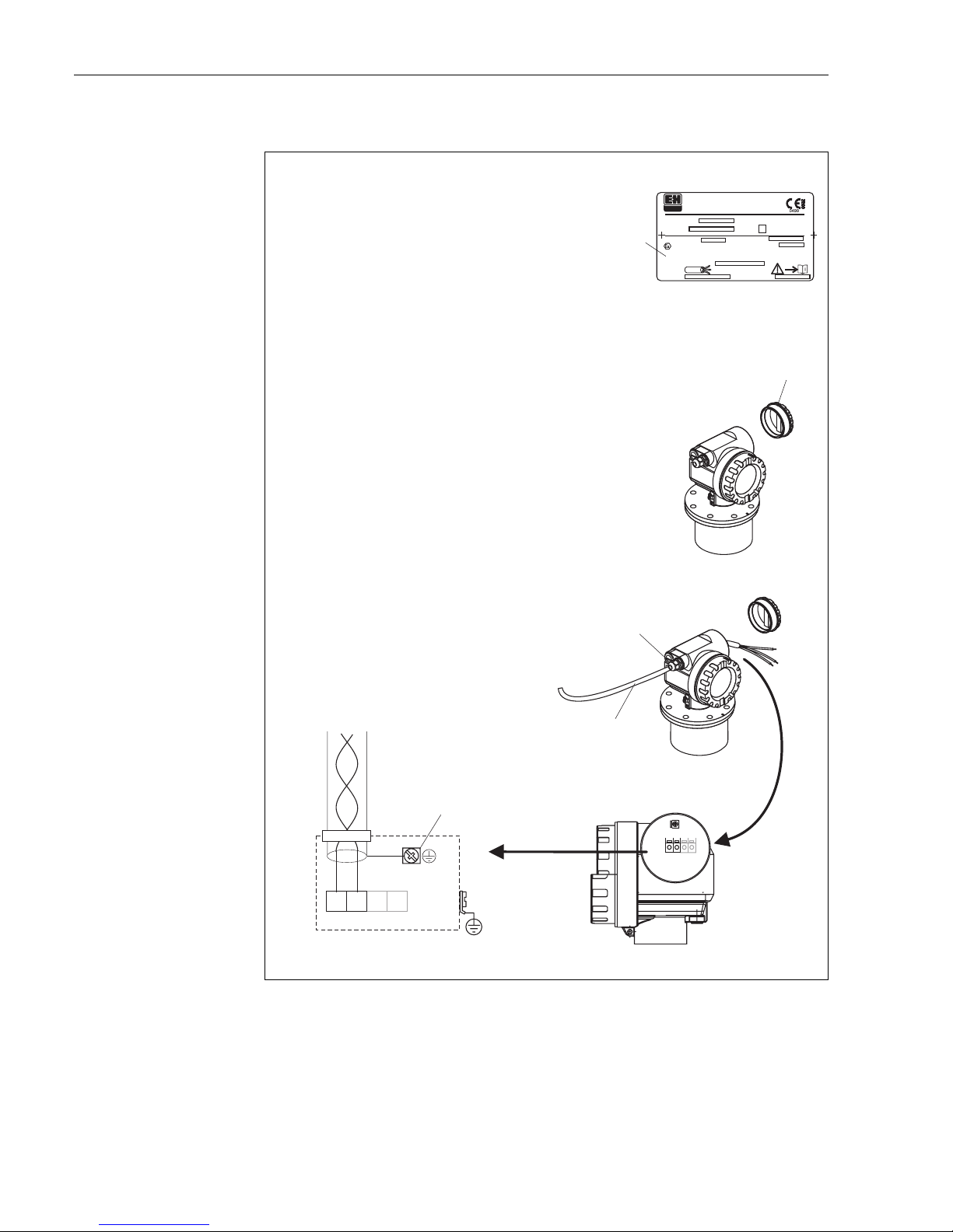
Wiring in T12 housing
L00-FMR2xxxx-04-00-00-en-022
2
-
-
4
3
1234
5
1
"
Ser.-No.:
Order Code:
D00886-A
t >85°C
x=
if modification
see sep. label
Dat./Insp.:
PN max.
T
Antenne
max. °C
79689 Maulburg
Made in Germany
T >70°C :
A
MICROPILOT M
ENDRESS+HAUSER
Profibus PA
PTB 00ATEX
II 1/2 G EEx ia IIC T6
IP65
xxxxxxxx
xxxxxxxx
1
3
4
11
8
7
3
4
1
2
+–
When you use the measuring system in hazardous areas, make sure you comply with
national standards and the specifications in the safety instructions (XA’s).
Make sure you use the specific cable gland.
Connect up the Micropilot M as follows:
Before unscrew housing cover (2) at seperate connection room
turn off the power supply!
Insert cable (3) through gland (5).
Use screened, twisted wire pair.
Only ground screening of the line (5) on sensor side.
Make connection (see pin assignment).
Tighten cable gland (4).
Screw on housing cover (2).
Switch on power supply.
l
l
l
l
l
plant
ground
Before connection please note the following:
PROFIBUS devices are marked on the nameplate (1).The
voltage is determined by the PROFIBUS standard and the
desired safety concept. (see chapter 4.3).
Connect potential matching line to transmitter earth terminal
before connecting up the device.
Tighten the locking screw:
It forms the connection between the antenna and the housing
earth potential.
l
l
l
Caution!
Micropilot M FMR231 with PROFIBUS PA Wiring
Endress+Hauser 25
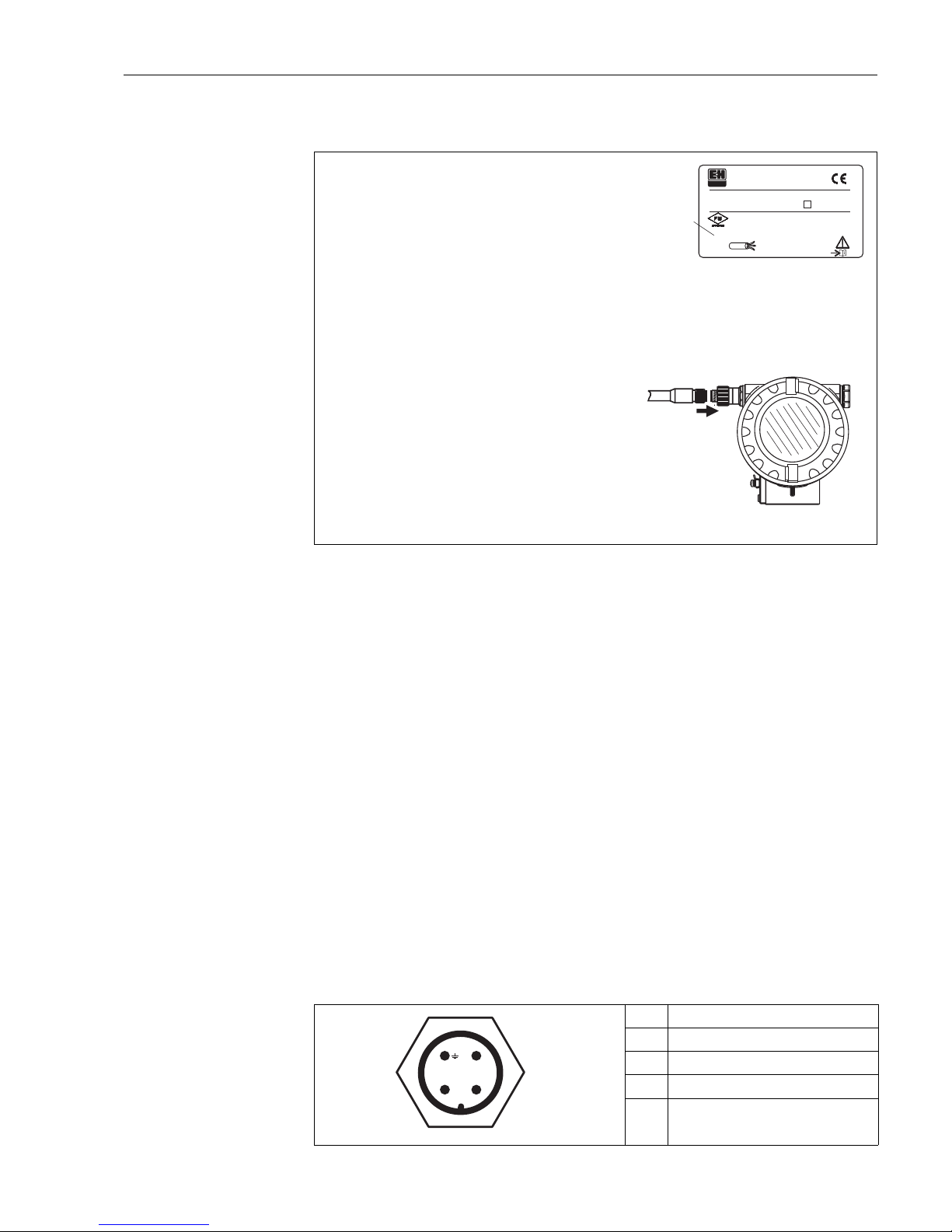
Wiring with M12 connector
L00-FMR230xx-04-00-00-en-004
Cable specification PROFIBUS
Twisted, screened pairs must be used. The following specification must be met for explosion
hazardous application (EN 50 020, FISCO model):
• Loop-resistance (DC): 15…150 Ω/km,
• Specific inductance: 0.4…1 mH/km,
• Specific capacitance: 80…200 nF/km
The following cable types can be used, for example
Non-Ex-area:
• Siemens 6XV1 830-5BH10 (black),
• Kerpen CEL-PE/OSCR/PVC/FRLA FB-02YS(ST)YFL (grey)
• Belden 3076F (orange)
Ex-area:
• Siemens 6XV1 830-5AH10 (blue),
• Belden 3076F, Kerpen CEL-PE/OSCR/PVC/FRLA FB-02YS(ST)YFL (blue)
Fieldbus plug connectors
For the versions with fieldbus plug connector (M12 or 7/8"), the signal line can be connected
without opening the housing.
Pin assignment of the M12 plug connector (PROFIBUS PA plug)
L00-FMxxxxxx-04-00-00-yy-016
Pin Meaning
1 Ground
2 Signal +
3 Signal -
4not connected
1
-
"
Ser.-No.:
Order Code:
D00899-A
t >85°C
x=
if modification
see sep. label
Dat./Insp.:
PN max.
T
Antenne
max. °C
T >70°C :
A
MICROPILOT M
ENDRESS+HAUSER
FCC ID LCG FMR2
INT.SAFE (entity) and
T-Codeper control drawing
Profibus PA
NEMA 4X
Assembled in USA
Patents
2
3
Before connection please note the following:
PROFIBUS devices are marked on the nameplate (1).The
voltage is determined by the PROFIBUS PA standard and the
desired safety concept. (see chapter 4.3).
Connect potential matching line to transmitter earth terminal
before connecting up the device.
Tighten the locking screw:
It forms the connection between the antenna and the housing
earth potential.
●
●
●
When you use the measuring system in hazardous areas, make sure you comply with
national standards and the specifications in the safety instructions (XA’s).
Make sure you use the specific cable gland.
On devices supplied with a certificate, the explosion protection
is designed as follows:
Housing F12/F23 - EEx ia:
Power supply must be intrinsically safe.
The electronics and the current output are galvanically
separated from the antenna circuit.
●
●
Caution!
The Micropilot M is connected as follows:
Insert plug (2) into bushing (3).
Screw firmly
Ground the device according to the desired safety concept.
●
●
●
2
1
3
4
+
–
nc

Wiring Micropilot M FMR231 with PROFIBUS PA
26 Endress+Hauser
4.2 Connecting the measuring unit
Cable entry
• Cable gland: M20x1.5
• Cable entry: G ½ or ½ NPT
• PROFIBUS-PA M12 plug
Supply voltage
The following values are the voltages across the terminals directly at the instrument:
Current consumption
approx 13 mA for the range of voltages given above
Overvoltage protector
The level transmitter Micropilot M with T12-housing (housing version "D", see ordering
information) is equipped with an internal overvoltage protector (600 V surge arrester) according to
DIN EN 60079-14 or IEC 60060-1 (impulse current test 8/20 µs, Î = 10 kA, 10 pulses). Connect
the metallic housing of the Micropilot M to the tank wall or screen directly with an electrically
conductive lead to ensure reliable potential matching.
Connection with M12 plug
The Micropilot M PROFIBUS-PA sensor version with M12 plug is supplied ready wired and need
only be connected to the bus by means of a suitable cord set.
Type Terminal voltage
minimum maximum
standard 9 V 32 V
EEx ia (FISCO model) 9 V 17, 5 V
EEx ia (Entity concept) 9 V 24 V

Micropilot M FMR231 with PROFIBUS PA Wiring
Endress+Hauser 27
4.3 Recommended connection
For maximum EMC protection please observe the following points:
• The external ground terminal on the transmitter must be connected to ground.
• The continuity of the cable screening between tapping points must be ensured.
• If potential equalisation is present between the individual grounding points, ground the screening
at each cable end or connect it to the device housing (as short as possible).
• If there are large differences in potential between grounding points, the grounding should run via
a capacitor that is suitable for high frequency use (e.g. ceramic 10 nF/250 V&).
"
Caution!
Applications, which are subject to the explosion prevention, permit only under special conditions
the repeated grounding of the protective screen , see to EN 60 079-14..
4.4 Degree of protection
• with closed housing: IP65, NEMA4X
• with open housing: IP20, NEMA1 (also ingress protection of the display)
• antenna: IP68 (NEMA6P)
4.5 Post-connection check
After wiring the measuring instrument, perform the following checks:
• Is the terminal allocation correct (→ Page 23 and Page 25)?
• Is the cable gland tight?
• Is the M12 connector screwed tight?
• Is the housing cover screwed tight?
• If auxiliary power is available:
Is the instrument ready for operation and does the liquid crystal display show any value?
Operation Micropilot M FMR231 with PROFIBUS PA
28 Endress+Hauser
5Operation
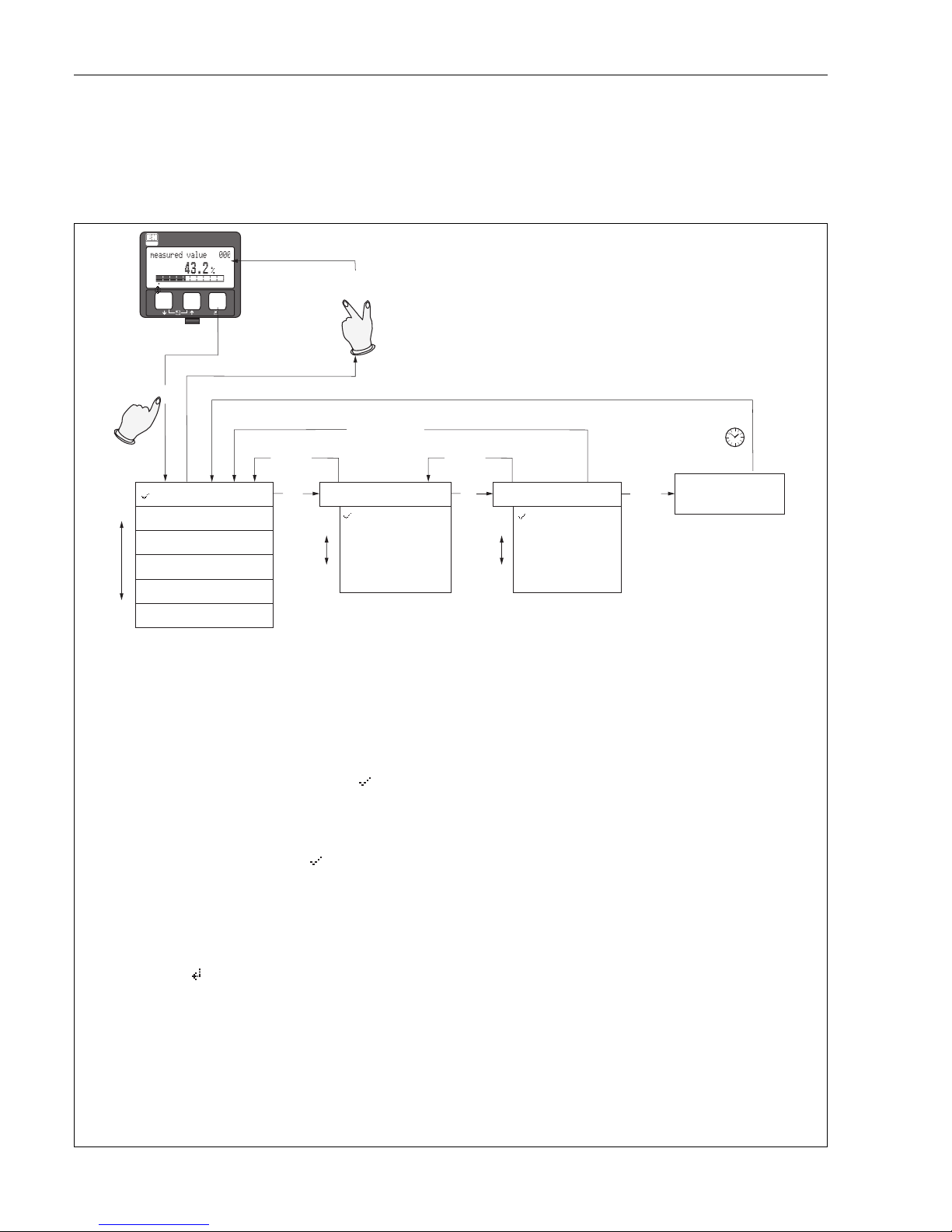
5.1 Quick operation guide
L00-FMR2xxxx-19-00-00-en-001
ENDRESS + HAUSER
E
+
–
X
X
X
X
S
SS
O
OO
FF
>3 s
F
...
2x
...
...
unknown
DC: < 1.9
DC: 1.9 ... 4
DC: 4 ... 10
DC: > 10
Selection and configuration in Operation menu:
Group Selection
Function Group
unction
Note!
Selection menus:
function
Typing in numerals and text:
numeral / text
function
function
Group selection
Measured value display
1.) Change from Measured Value Display to by pressing
2.) Press or to select the required (e.g.. "basic setup (00)") and confirm by pressing
(e.g. "tank shape (002)") is selected.
The active selection is marked by a in front of the menu text.
3.) Activate Edit mode with or .
a) Select the required in selected (e.g. "tank shape (002)") with or .
b) confirms selection appears in front of the selected parameter
c) confirms the edited value system quits Edit mode
d) + (= ) interrupts selection system quits Edit mode
a) Press or to edit the first character of the (e.g. "empty calibr. (005)")
b) positions the cursor at the next character (a) until you have completed your input
c) if a symbol appears at the cursor, press to accept the value entered
system quits Edit mode
d) + (= ) interrupts the input,
4) Press to select the next (e.g. "medium property (003)")
5) Press + (= ) once return to previous (e.g. "tank shape (002)")
Press + (= ) twice return to
6) Press + (= ) to return to
F
SO
O
SO
F
S
X
S
F
S
F
F
OS X
OS
F
OX
F
OS X
OS
OX
Ü
Ü
Ü
Ü
Ü
Ü
Ü
First f
continue with
system quits Edit mode
Ü
Parameter
Return to
Group Selection
basic setup
safety settings
linearisation
tank shape
dome ceiling
horizontal cyl
bypass
stilling well
flat ceiling
sphere
medium property
extended calibr.
Micropilot M FMR231 with PROFIBUS PA Operation
Endress+Hauser 29
5.1.1 General structure of the operating menu
The operating menu is made up of two levels:
• Function groups (00, 01, 03, …, 0C, 0D): The individual operating options of the instrument
are split up roughly into different function groups. The function groups that are available include,
e.g.: "basic setup", "safety settings", "output", "display", etc.
• Functions (001, 002, 003, …, 0D8, 0D9): Each function group consists of one or more
functions. The functions perform the actual operation or parameterisation of the instrument.
Numerical values can be entered here and parameters can be selected and saved. The available
functions of the “basic setup” (00) function group include, e.g.: "tank shape" (002),
"medium property" (003), "process cond." (004), "empty calibr." (005), etc.
If, for example, the application of the instrument is to be changed, carry out the following
procedure:
1. Select the “basic setup” (00) function group.
2. Select the "tank shape" (002) function (where the existing tank shape is selected).
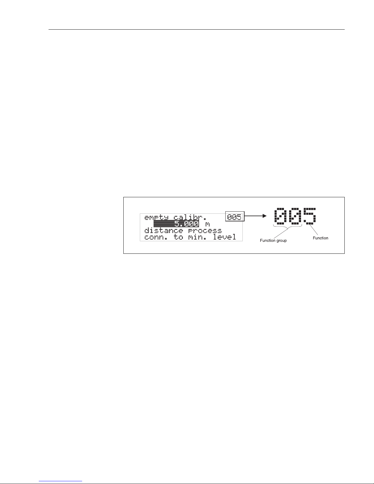
5.1.2 Identifying the functions
For simple orientation within the function menus (see Page 98 ff.), for each function a position is
shown on the display.
L00-FMRxxxxx-07-00-00-en-005
The first two digits identify the function group:
The third digit numbers the individual functions within the function group:
Hereafter the position is always given in brackets (e.g. "tank shape" (002)) after the described
function.
• basic setup 00
• safety settings 01
• linearisation 04
. . .
• basic setup 00 → • tank shape 002
• medium property 003
• process cond. 004
. . .
Operation Micropilot M FMR231 with PROFIBUS PA
30 Endress+Hauser
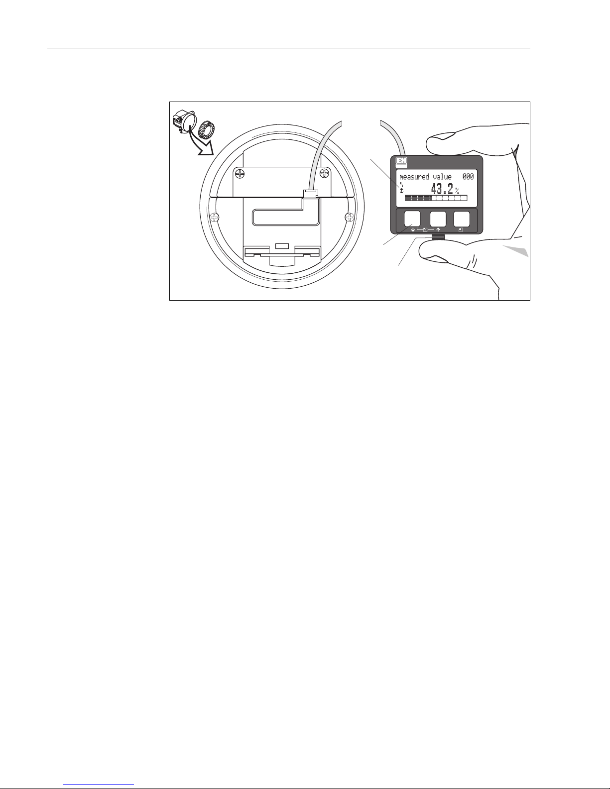
5.2 Display and operating elements
L00-FMxxxxxx-07-00-00-en-001
Fig. 2: Layout of the display and operating elements
The VU331 LCD display can be removed to ease operation by simply pressing the snap-fit (see
graphic above). It is connected to the device by means of a 500 mm cable.
!
Note!
To access the display the cover of the electronic compartment may be removed even in hazardous
area (IS and XP).
ENDRESS + HAUSER
E
+
–
EN
DRESS+HA
USER
M
ICROPILOT
II
ENDRESS+HAUSER
MICROPILOTII
IP65
IP65
O
rd
e
r
C
o
d
e
:
Ser
.-No
.:
Order
Code:
Ser.-No.:
M
e
ss
b
e
r
eic
h
M
ea
su
ring
rang
e
Messbereich
Measuring
range
U
1
6
...3
6
V
D
C
4
...20
m
A
U
16...36
V
DC
4...20
mA
m
a
x.
2
0
m
max.
20
m
MadeinGermany Maulburg
MadeinGermany Maulburg
T>7
0
°C
:
A
t>
8
5°
C
T>70°C
:
A
t
>85°C
LCD
(liquid crystal display)
Symbols
3 keys
snap-fit
 Loading...