

Endress+Hauser micropilot M FMR 230, micropilot M FMR 240, micropilot M FMR 231 Technical Information
Technical Information
TI 345F/00/en
Level-Radar
micropilot M
FMR 230/231/240
Smart Transmitter for continuous and
non-contact level measurement
Cost-effective 4…20 mA 2-wire technology
Suitable for hazardous locations
Features and benefits
• 2-wire technology, low price:
A real alternative to differential
pressure, floats and displacers.
2-wire technology reduces wiring costs
and allows easy implementation into
existing systems.
• Non-contact measurement:
Measurement is almost independent
from product properties.
• Easy on-site operation via menu-driven
alphanumeric display.
• Easy commissioning, documentation
and diagnostics via operating software
(ToF Tool).
• 2 frequency ranges – approx. 6 and
26 GHz:
No compromises, the right frequency
for every application.
• HART or PROFIBUS-PA respectively
Foundation Fieldbus protocol.
• High temperatures:
Suitable for process temperatures up to
+200 °C (392 °F), up to 400 °C (752 °F)
with high-temperature antenna.
• Rod antenna with inactive length:
Reliable measurement in narrow
nozzles, with condensation and
build-up in the nozzle.
Application
The Micropilot M is used for continuous,
non-contact level measurement of
liquids, pastes, and slurries.
The measurement is not affected by
changing media, temperature changes,
gas blankets or vapours.
• The FMR 230 is especially suited for
measurement in buffer and process
tanks.
• The FMR 231 has its strengths
wherever high chemical compatibility is
required.
• The FMR 240 with the small (1½") horn
antenna is ideally suited for small
vessels. Additionally, it provides an
accuracy of ±3 mm.
FMR 231
FMR 230
FMR 240
www.aotewell.com
www.fa-market.com
info@aotewell.com
AoteWell International.inc
sales@aotewell.com
Tel: +852-6563-2160
Micropilot M
2 Endress+Hauser
Function and system design
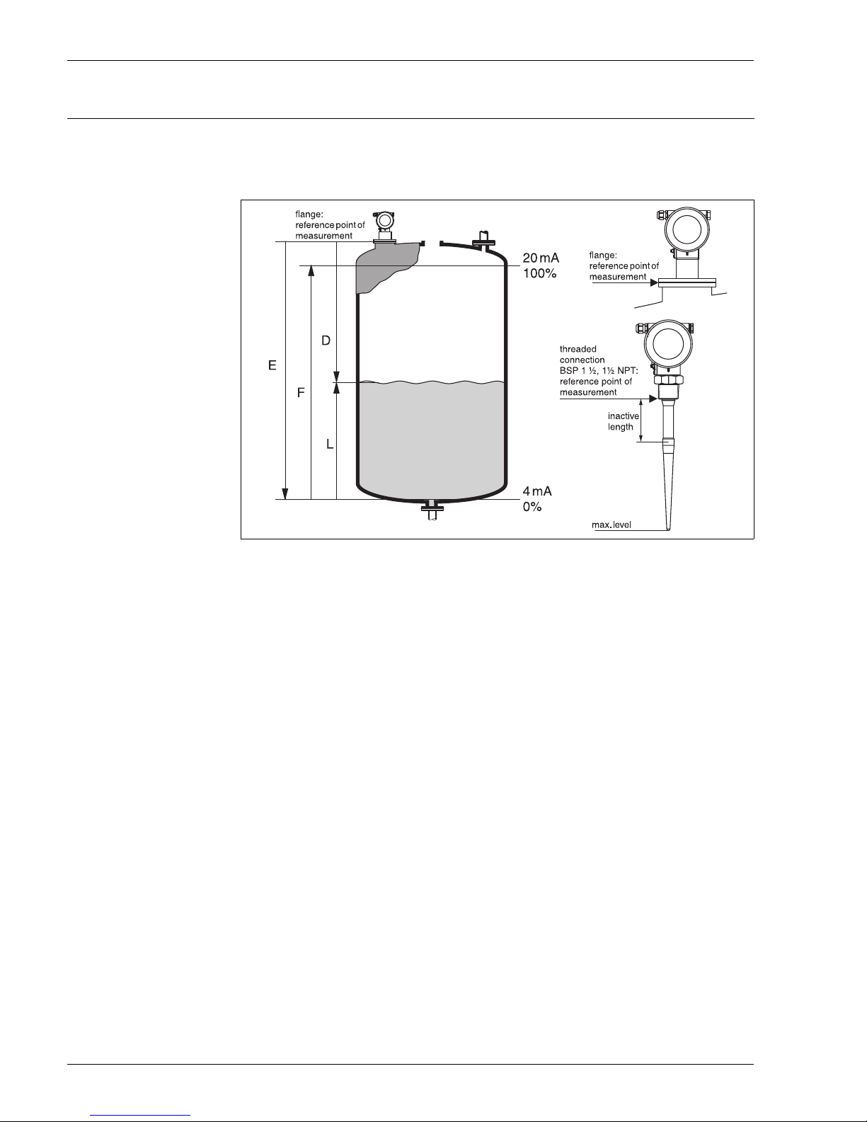
Measuring principle The Micropilot is a "downward-looking" measuring system, operating based on the time-of-flight
method. It measures the distance from the reference point (process connection) to the product
surface. Radar impulses are emitted by an antenna, reflected off the product surface and
received again by the radar system.
Input
The reflected radar impulses are received by the antenna and transmitted into the electronics.
A microprocessor evaluates the signal and identifies the level echo caused by the reflection of the
radar impulse at the product surface. The unambiguous signal identification is accomplished by
the PulseMaster software, based on many years of experience with time-of-flight technology.
The mm-accuracy of the Micropilot S could be achieved with the patented algorithms of the
PhaseMaster software.
The distance D to the product surface is proportional to the time of flight t of the impulse:
D = c · t/2,
with c being the speed of light.
Based on the known empty distance E, the level L is calculated:
L = E – D
Refer to the above figure for the reference point for "E".
The Micropilot is equipped with functions to suppress interference echoes. The user can activate
these functions. They ensure that interference echoes (i.e. from edges and weld seams) are not
interpreted as level echo.
Output
The Micropilot is commissioned by entering an empty distance E (=zero), a full distance F (=span)
and an application parameter. The application parameter automatically adapts the instrument to
the measuring conditions. The data points “E” and “F” correspond with 4mA and 20mA for
instruments with current output. They correspond with 0 % and 100 % for digital outputs and the
display module.
A linearization, based on a table entered either manually or semi-automatically, can be activated
locally or remotely. This function provides a measurement in engineering units and a linear output
signal for spheres, horizontal cylindrical tanks and vessels with conical outlet.
L00-FMR2xxxx-15-00-00-en-001
www.aotewell.com
www.fa-market.com
info@aotewell.com
AoteWell International.inc
sales@aotewell.com
Tel: +852-6563-2160
Micropilot M
Endress+Hauser 3
Equipment architecture Stand-alone
The Micropilot M can be used for measurement in a stilling well / bypass as well as in free space.
The instrument provides a 4…20 mA output with HART protocol, or PROFIBUS-PA respectively
Foundation Fieldbus communication.
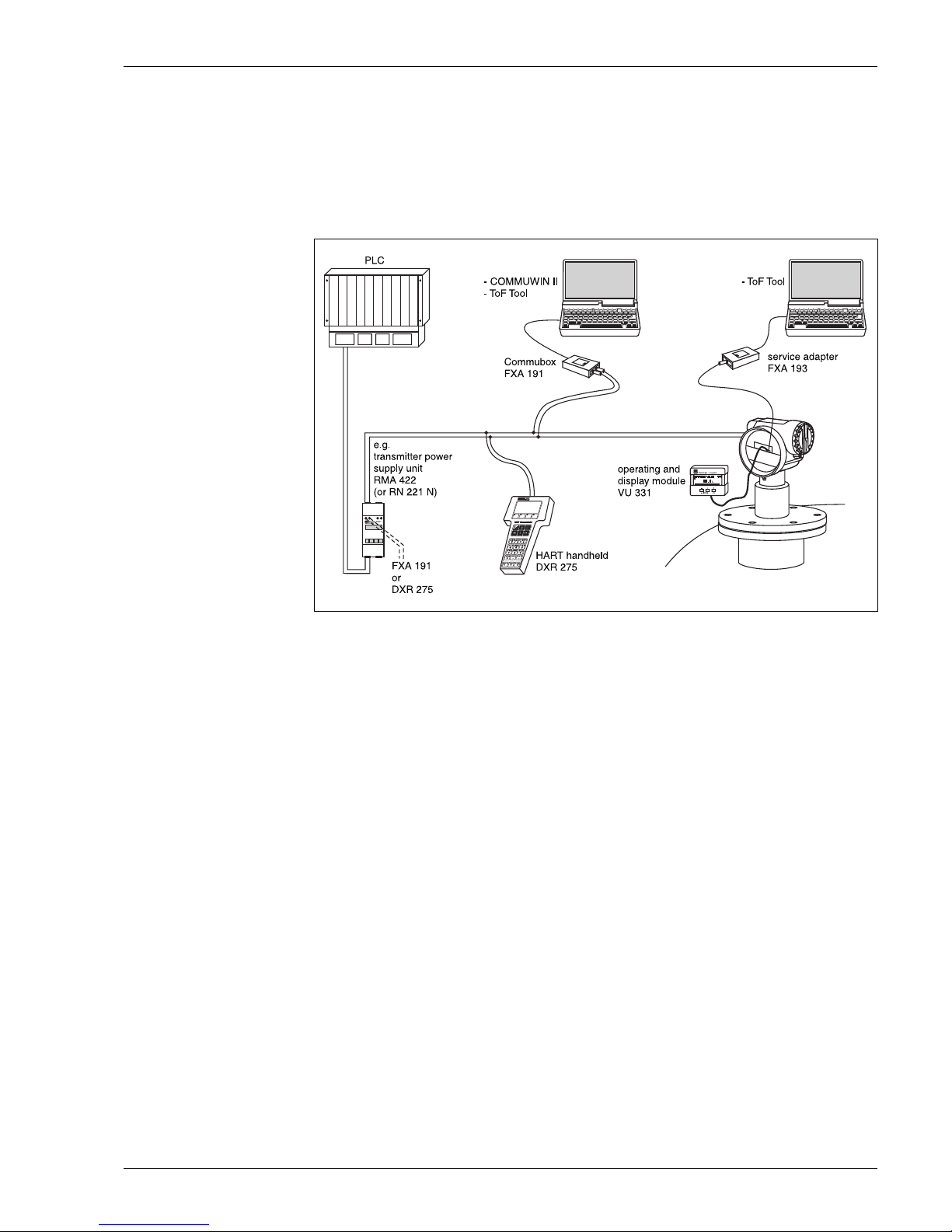
4…20 mA output with HART protocol.
The complete measuring system consists of:
On-site operation:
• with display and operating module VU 331,
• with a Personal Computer, FXA 193 and the operating software ToF Tool.
The ToF Tool is a graphical operating software for instruments from Endress+Hauser that
operate based on the time-of-flight principle (radar, ultrasonic, guided micro-impulse). It assists
with commissioning, securing data, signal analysis and documentation of the measuring point.
Remote operation:
• with HART handheld DXR 275,
• with a Personal Computer, Commubox FXA 191 and the operating software COMMUWIN II
respectively ToF Tool.
L00-FMR2xxxx-14-00-06-en-001
www.aotewell.com
www.fa-market.com
info@aotewell.com
AoteWell International.inc
sales@aotewell.com
Tel: +852-6563-2160
Micropilot M
4 Endress+Hauser
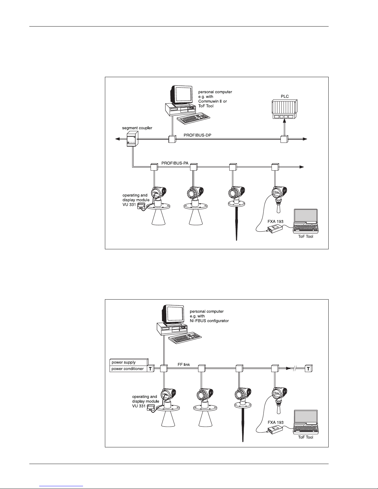
System integration via PROFIBUS-PA
A maximum of 32 transmitters (8 if mounted in an explosion hazardous location EEx ia IIC
according to FISCO-model) can be connected to the bus. The segment coupler provides the
operating voltage to the bus. Both on-site as well as remote operation are possible.
The complete measuring system consists of:
System integration via Foundation Fieldbus
A maximum of 32 transmitters (standard, EEx em or EEx d) can be connected to the bus. For
protection class EEx ia IIC: the max. number of transmitters depends on the established rules and
standards for intrinsically safe circuits (EN 60070-14), proof of intrinsically safety. Both on-site as
well as remote operation are possible. The complete measuring system consists of:
L00-FMR2xxxx-14-00-06-en-002
L00-FMR2xxxx-14-00-06-en-003
www.aotewell.com
www.fa-market.com
info@aotewell.com
AoteWell International.inc
sales@aotewell.com
Tel: +852-6563-2160
Micropilot M
Endress+Hauser 5
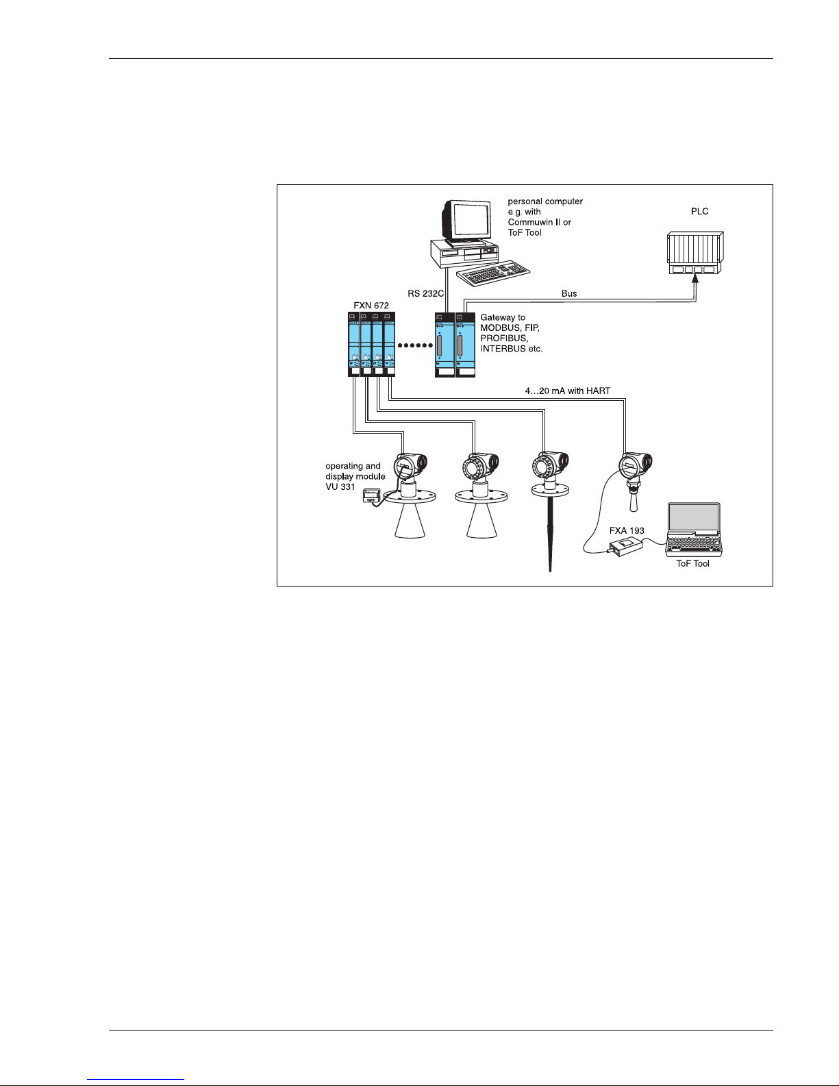
System integration via Rackbus
Multiple transmitters Micropilot M (or other instruments) can be connected to a higher-level bus
system via a Gateway ZA:
• Every HART transmitter via one interface module FXN 672 each.
• Gateways are available for MODBUS, FIP, PROFIBUS, INTERBUS etc.
• Both on-site as well as remote operation are possible.
L00-FMR2xxxx-14-00-06-en-006
www.aotewell.com
www.fa-market.com
info@aotewell.com
AoteWell International.inc
sales@aotewell.com
Tel: +852-6563-2160
Micropilot M
6 Endress+Hauser
Input
Measured variable The measured variable is the distance between a reference point (refer to fig. on page 2) and a
reflective surface (i.e. medium surface).
The level is calculated based on the tank height entered.
The level can be converted into other units (volume, mass) by means of a linearization.
Measuring range The usable measuring range depends on the size of the antenna, the reflectivity of the medium,
the mounting location and eventual interference reflections.
The following tables describe the groups of media as well as the achievable measuring range as
a function of application and media group. If the dielectric constant of a medium is unknown, it is
recommended to assume media group B to ensure a reliable measurement.
1) Treat Ammonia NH3 as a medium of group A, i.e. always use a stilling well.
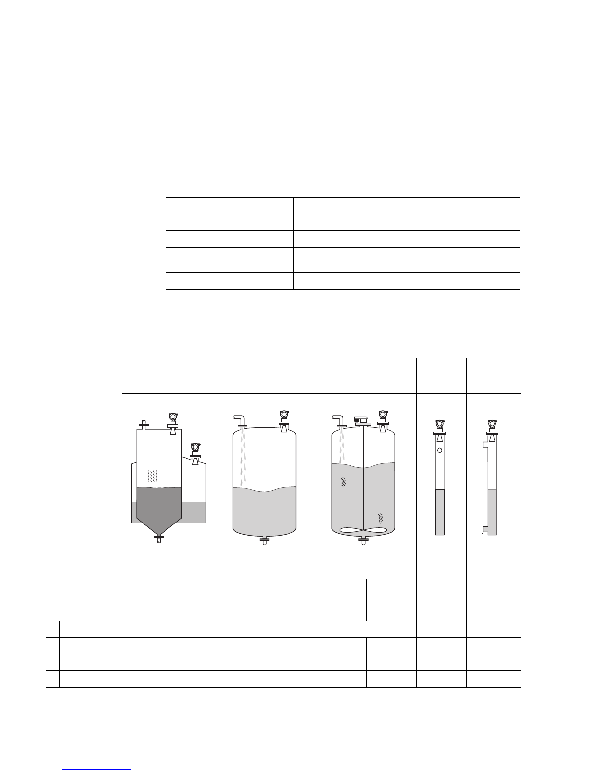
Measuring range depending on vessel type, conditions and product for Micropilot M
FMR 230 and FMR 231:
2) possible, i.e. with stilling well in bypass.
Product class DK (
εr) Examples
A 1.4 … 1.9 non-conducting liquids, e.g. liquefied gas
1)
B 1.9 … 4 non-conducting liquids, e.g. benzene, oil, toluene, …
C 4 … 10 e.g. concentrated acids, organic solvents, esters, aniline, alcohol,
acetone, …
D > 10 conducting liquids, e.g. aqueous solutions, dilute acids and alkalis
Product class Storage tank
(scarce
draining/filling)
Buffer tank
(continuous
draining / filling)
Tank with single stage
propeller agitator
Stilling well Bypass
Measuring range Measuring range Measuring range
Measuring
range
Measuring
range
FMR 230:
DN1506"DN200/250
8" / 10"
DN1506"DN200/250
8" / 10"
DN150
6"
DN200/250
8" / 10"
DN80…250
3"…10"
DN80…150
3"…6"
FMR 231: Rod antenna — Rod antenna — Rod antenna — — —
A DK(
εr)=1.4…1.9 to use the stilling well (20 m / 67 ft) 20 m/67 ft
2)
B DK(εr)=1.9…4 10 m/33 ft 15 m/50 ft 5 m/16 ft 7.5 m/24 ft 4 m/13 ft 6 m/20 ft 20 m/67 ft
2)
C DK(εr)=4…10 15 m/50 ft 20 m/67 ft 7.5 m/24 ft 10 m/33 ft 6 m/20 ft 8 m/27 ft 20 m/67 ft 20 m/67 ft
D DK(
εr)>10 20 m/67 ft 20 m/67 ft 10 m/33 ft 12.5 m/42 ft 8 m/27 ft 10 m/33 ft 20 m/67 ft 20 m/67 ft
www.aotewell.com
www.fa-market.com
info@aotewell.com
AoteWell International.inc
sales@aotewell.com
Tel: +852-6563-2160
Micropilot M
Endress+Hauser 7
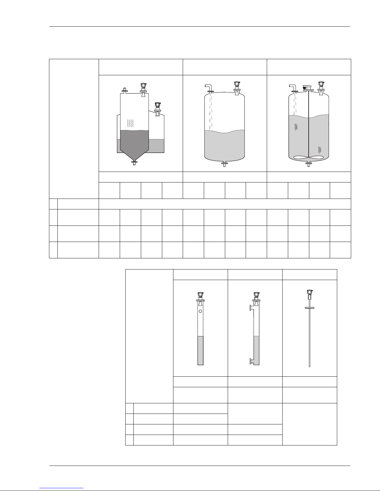
Measuring range depending on vessel type, conditions, and product for Micropilot M
FMR 240:
Product class Storage tank
(scarce draining/filling)
Buffer tank
(continuous draining / filling)
Tank with single stage propeller
agitator
Measuring range Measuring range Measuring range
FMR 240:
1½"
40mm
DN502"DN803"DN1004"1½"
40mm
DN502"DN803"DN1004"1½"
40mm
DN502"DN803"DN100
4"
A DK(
εr)=1.4…1.9 to use the stilling well (20 m / 67 ft)
B DK(
εr)=1.9…4
3 m /
10 ft
5 m /
16 ft
10 m /
33 ft
15 m /
50 ft
2 m /
7ft
2.5 m /
8ft
5 m /
16 ft
7.5 m /
25 ft
1 m /
3ft
1 m /
3ft
2 m /
7ft
3 m /
10 ft
C DK(
εr)=4…10
6 m /
20 ft
10 m /
33 ft
15 m /
50 ft
20 m /
67 ft
3 m /
10 ft
5 m /
16 ft
7.5 m /
25 ft
10 m /
33 ft
1.5 m /
5ft
2 m /
7ft
3 m /
10 ft
5 m /
16 ft
D DK(
εr)>10
9 m /
30 ft
15 m /
50 ft
20 m /
67 ft
20 m /
67 ft
5 m /
16 ft
7.5 m /
25 ft
10 m /
33 ft
12.5 m
/ 42 ft
2 m /
7ft
3 m /
10 ft
5 m /
16 ft
7 m /
23 ft
Product class Stilling well Bypass Wave Guide antenna
Measuring range Measuring range Measuring range
FMR 240:
1½" / 40mm … DN100
1½"…4"
DN50…100
2"…4"
Wave Guide antenna
A DK(
εr)=1.4…1.9 20 m/ 67 ft
see pipe antenna
depending
on pipe length,
max. 2.8 m (9.2 ft)
B DK(
εr)=1.9…4 20 m/ 67 ft
C DK(
εr)=4…10 20 m/ 67 ft 20 m/ 67 ft
D DK(
εr)>10 20 m/ 67 ft 20 m/ 67 ft
www.aotewell.com
www.fa-market.com
info@aotewell.com
AoteWell International.inc
sales@aotewell.com
Tel: +852-6563-2160

Micropilot M
8 Endress+Hauser
Measuring conditions Note!
Please use FMR 230 respectively FMR 231 for boiling surfaces or in case of a tendency for
foaming.
The maximum measuring range of the FMR240 may decrease in case of heavy steam
development, depending on density, temperature and composition of the steam (-> please
use FMR 230 respectively FMR 231). Please use FMR 230 in stilling well for the
measurement of ammonia NH
3
.
• The measuring range begins, where the beam hits the tank bottom. Particularly with dish
bottoms or conical outlets the level cannot be detected below this point.
• In case of media with a low dielectric constant (groups A and B), the tank bottom can be visible
through the medium at low levels. In order to guarantee the required accuracy in these cases,
it is recommended to position the zero-point at a distance (C) above the tank bottom
• In principle it is possible to measure up to the tip of the antenna. However, due to considerations
regarding corrosion and build-up, the end of the measuring range should not be chosen any
closer than 50 mm (2”) to the tip of the antenna.
• The smallest possible measuring range (B) depends on the antenna version.
• The tank diameter should be greater than (D), the tank height at least (H).
• Depending on its consistence, foam can either absorb microwaves or reflect them off the foam
surface. Measurement is possible under certain conditions.
B [m / inch] C [mm / inch] D [m / inch] H [m / ft]
FMR 230 / 231 > 0.5 / > 20 150…300 / 6…12 > 1 / > 40 > 1.5 / > 5
FMR 240 > 0.2 / > 8 50…150 / 2…6 > 0.2 / > 8 > 0.3 / > 1
L00-FMR2xxxx-17-00-00-en-005
www.aotewell.com
www.fa-market.com
info@aotewell.com
AoteWell International.inc
sales@aotewell.com
Tel: +852-6563-2160

Micropilot M
Endress+Hauser 9
Output
Output signal • 4…20 mA with HART protocol
• PROFIBUS-PA
• Foundation Fieldbus (FF)
Signal on alarm Error information can be accessed via the following interfaces:
• Local display:
– Error symbol (see page 27)
– Plain text display
• Current output
• Digital interface
Auxiliary energy
Electrical connection Terminal compartment
Two housings are available:
• Housing F 12 with additionally sealed terminal compartment for standard or EEx ia
• Housing T 12 with separate terminal compartment for standard, EEx e or EEx d.
L00-FMR2xxxx-04-00-00-en-001
www.aotewell.com
www.fa-market.com
info@aotewell.com
AoteWell International.inc
sales@aotewell.com
Tel: +852-6563-2160
Micropilot M
10 Endress+Hauser
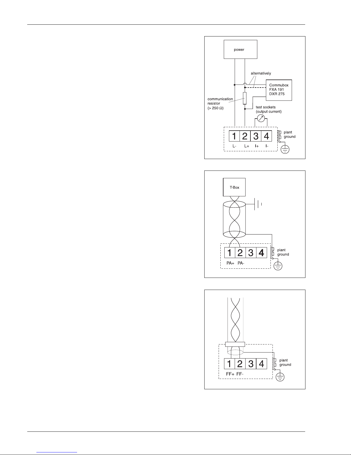
Terminal assignment 4…20 mA with HART
The 2-wire cable is connected to the screw
terminals (wire diameter 0.5…2.5mm) in the
terminal compartment.
Use 2-wire twisted pair cable with screen for
the connection.
Protective circuitry against reverse polarity,
RFI, and over-voltage peaks is built into the
device (refer to TI 241F »basics for EMCtests«).
Terminal assignment PROFIBUS-PA
The digital communication signal is transmitted
to the bus via a 2-wire connection. The bus also
provides the auxiliary energy.
Please use 2-wire twisted pair cable with
screen.
Hints regarding architecture and grounding of
the network can be found in BA 198F
»projecting hints PROFIBUS-PA« and the
specification for PROFIBUS-PA.
Terminal assignment Foundation Fieldbus
The digital communication signal is transmitted
to the bus via a 2-wire connection. The bus
also provides the auxiliary energy.
Please use 2-wire twisted pair cable with
screen. Further cable specifications can be
found in the FF specification or the
IEC 61158-2.
Further hints regarding architecture and
grounding of the network can be found at the
Internet address »http://www.fieldbus.org«.
L00-FMR2xxxx-04-00-00-en-002L00-FMR2xxxx-04-00-00-en-003L00-FMR2xxxx-04-00-00-en-007
www.aotewell.com
www.fa-market.com
info@aotewell.com
AoteWell International.inc
sales@aotewell.com
Tel: +852-6563-2160
Micropilot M
Endress+Hauser 11
Load HART Minimum load for HART communication: 250 Ω
Cable entry Cable gland: M20x1.5 or Pg13.5
Cable entry: G ½ or ½ NPT
PROFIBUS-PA M12 plug
Fieldbus Foundation 7/8" plug
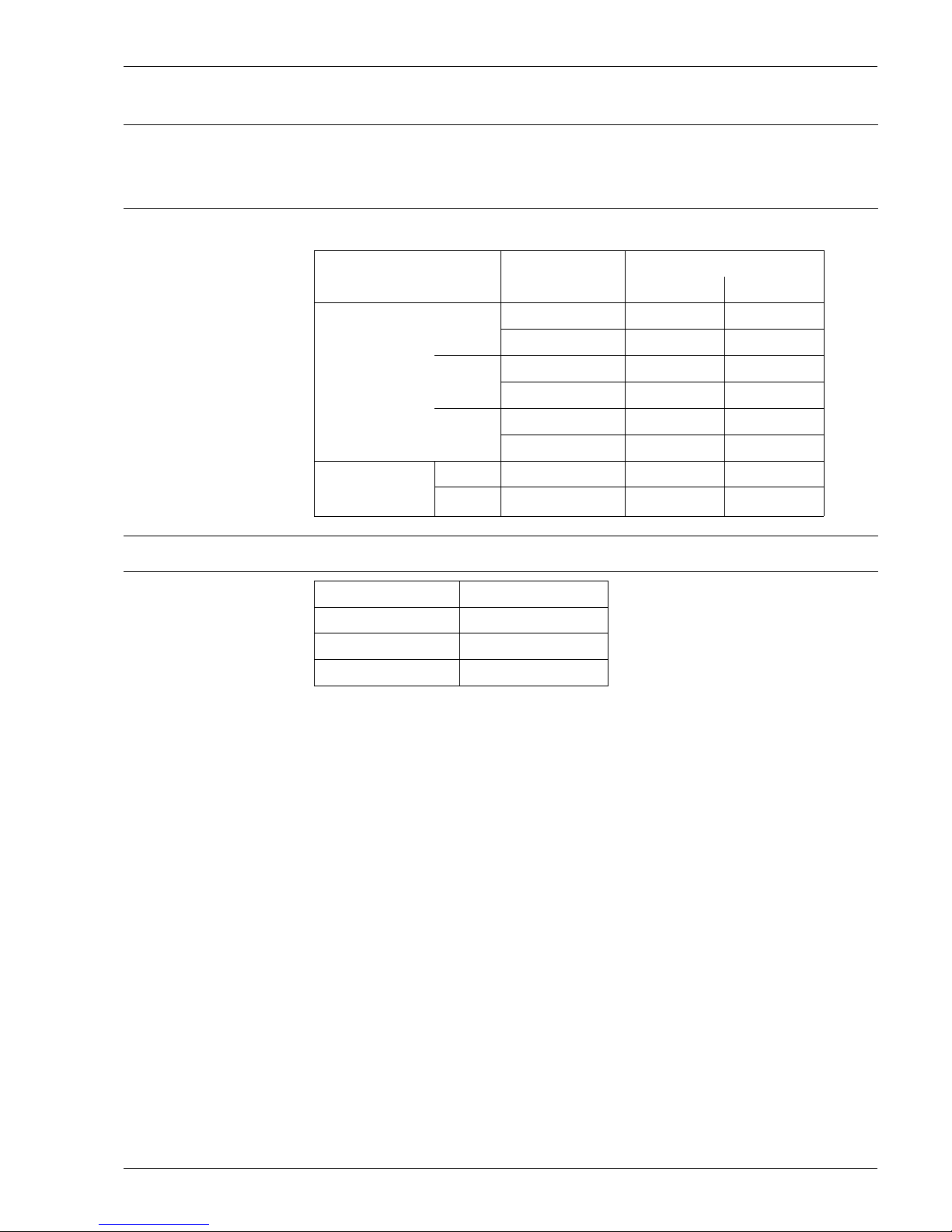
Supply voltage The following values are the voltages across the terminals directly at the instrument:
.
Power consumption Normal operation: min. 60 mW, max. 900 mW
Current consumption .
Communication
Current
consumption
Terminal voltage
minimal maximal
HART
standard
4 mA 16 V 36 V
20 mA 7.5 V 36 V
EEx ia
4 mA 16 V 30 V
20 mA 7.5 V 30 V
EEx em
EEx d
4 mA 16 V 30 V
20 mA 11 V 30 V
Fixed current
(measured value
transferred at HART)
standard 11 mA 10 V 36 V
EEx ia 11 mA 10 V 30 V
Communication Current consumption
HART 3.6…22 mA
PROFIBUS-PA ca. 13 mA
Foundation Fieldbus (FF) ca. 15 mA
www.aotewell.com
www.fa-market.com
info@aotewell.com
AoteWell International.inc
sales@aotewell.com
Tel: +852-6563-2160

Micropilot M
12 Endress+Hauser
Performance characteristics
Reference operating
conditions
• temperature = +20 °C (68 °F) ±5 °C (9 °F)
• pressure = 1013 mbar abs. (14.7 psia) ±20 mbar (0.3 psi)
• relative humidity (air) = 65 % ±20%
• ideal reflector
• no major interference reflections inside the signal beam
Maximum measured error Typical statements for reference conditions, include linearity, repeatability, and hysteresis:
.
Resolution Digital / analog in % 4…20 mA
• FMR 230: 1mm / 0.1 % of measuring range
• FMR 231: 1mm / 0.1 % of measuring range
• FMR 240: 1mm / 0.1 % of measuring range
Reaction time The reaction time depends on the parameter settings (min. 1 s). In case of fast level changes, the
instrument needs the reaction time to indicate the new value.
Influence of ambiente
temperature
0.006% / 10 K referring to max. measuring range
Type of device to 10 m ex 10 m
FMR 230
±10 mm ±0.1% of measuring range
FMR 231
±10 mm ±0.1% of measuring range
FMR 240
±3 mm ±0.03% of measuring range
www.aotewell.com
www.fa-market.com
info@aotewell.com
AoteWell International.inc
sales@aotewell.com
Tel: +852-6563-2160
Micropilot M
Endress+Hauser 13
Operating conditions / Installation
Installation instructions
Beam angle The beam angle is defined as the angle α where the energy density of the radar waves reaches
half the value of the maximum energy density (3dB-width). Microwaves are also emitted outside
the signal beam and can be reflected off interfering installations.
Beam angle in dependence of antenna type (diameter).
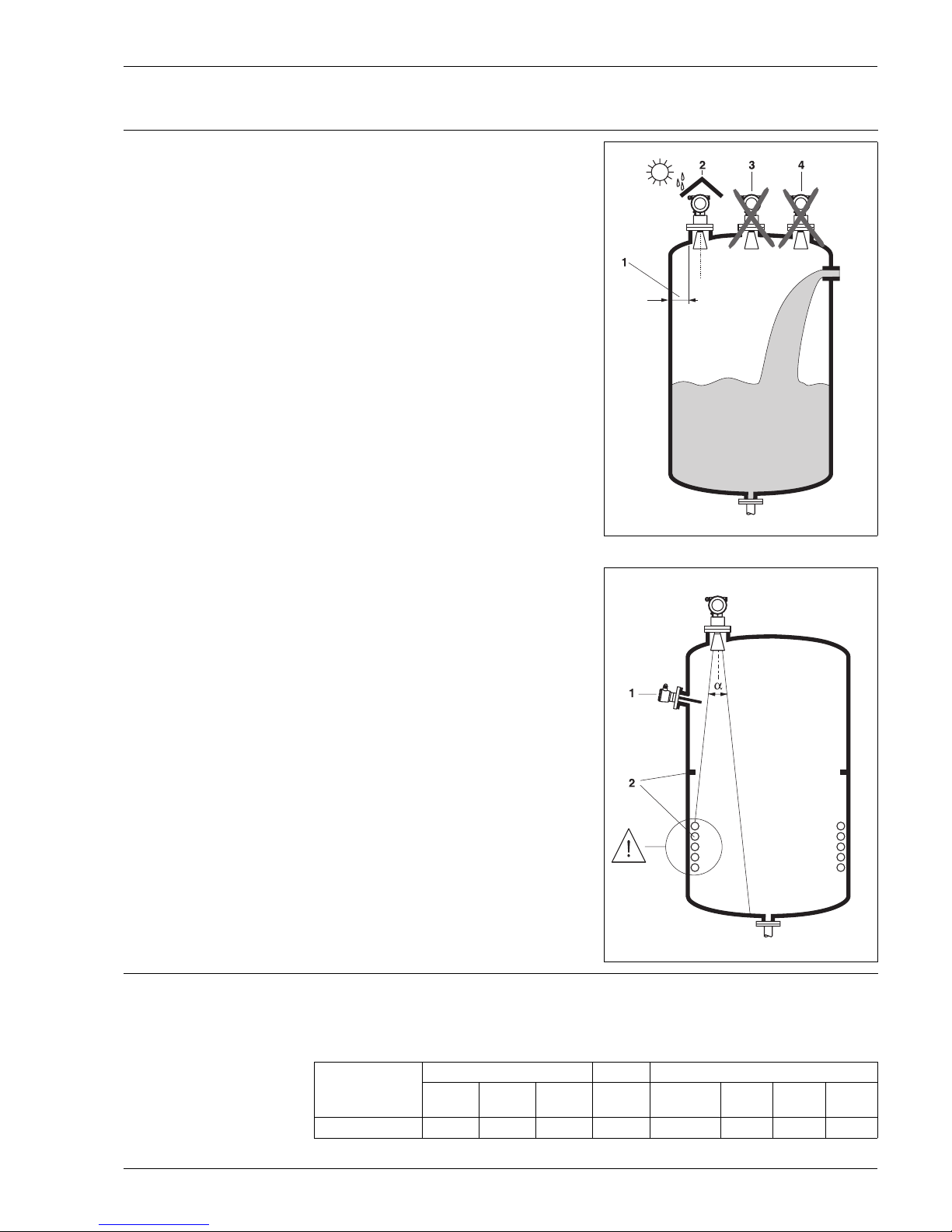
Orientation
• Recommended distance (1) wall – outer
edge of nozzle: ~1/6 of tank diameter
(FMR 230/231: min. 30 cm (12“),
FMR 240: min. 15 cm (6“)).
• Not in the centre (3), interference can cause
signal loss.
• Not above the fill stream (4).
• It is recommended to use a weather
protection cover (2) in order to protect the
transmitter from direct sun or rain. Assembly
and disassembly is simply done by means of
a tension clamp (see »Accessories« on
page 39).
Tank installations
• Avoid any installations (1), like limit switches,
temperature sensors, etc., inside the signal
beam (refer to beam angle).
• Symmetrical installations (2), i.e. vacuum
rings, heating coils, baffles, etc., can also
interfere with the measurement.
Optimization options
• Antenna size: the bigger the antenna, the
smaller the beam angle, the less interference
echoes.
• Mapping: the measurement can be
optimized by means of electronic
suppression of interference echoes.
• Antenna alignment: refer to "optimum
mounting position"
• Stilling well: a stilling well respectively a
Wave Guide antenna can always be used to
avoid interference.
Please contact Endress+Hauser for further
information.
L00-FMR2xxxx-17-00-00-xx-001
L00-FMR2xxxx-17-00-00-xx-002
Antenna size FMR 230 FMR 231 FMR 240
DN1506"DN2008"DN250
10"
Rod 1½" / 40 mm DN502"DN803"DN100
4"
Beam angle
α 23° 19° 15° 30° 23° 18° 10° 8°
www.aotewell.com
www.fa-market.com
info@aotewell.com
AoteWell International.inc
sales@aotewell.com
Tel: +852-6563-2160
Micropilot M
14 Endress+Hauser
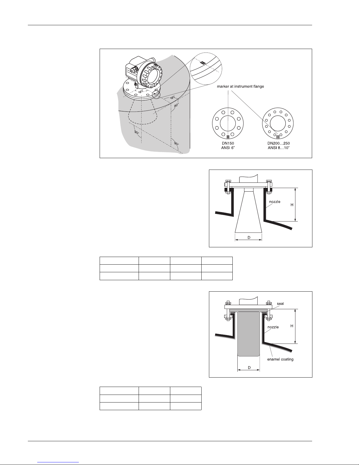
Installation in tank
(free space) FMR 230
Optimum mounting position
Standard installation
• Observe installation instructions on page 13.
• Marker is aligned towards tank wall.
• The marker is always exactly in the middle
between two bolt-holes in the flange.
• After mounting, the housing can be turned
350° in order to simplify access to the display
and the terminal compartment.
• The horn antenna must extend below the
nozzle, otherwise use antenna extension
FAR10.
• Align horn antenna vertically.
Antenna size 150 mm / 6" 200 mm / 8" 250 mm / 10"
D [mm / inch] 146 / 5.8 191 / 7.5 241 / 9.5
H [mm / inch] < 205 / < 8.1 < 290 / < 11.5 < 380 / <15
Installation instructions for enamelled
antenna
• Refer to standard installation.
• Attention!
Do not hit or chip the enamelled antenna,
the coating can be damaged.
Antenna size 150 mm / 6" 200 mm / 8"
D [mm / inch] 140 / 5.5 158 / 6.2
H [mm / inch] < 219 / 8.6 < 269 / 10.6
L00-FMR230xx-17-00-00-en-001
L00-FMR230xx-17-00-00-en-002L00-FMR230xx-17-00-00-en-008
www.aotewell.com
www.fa-market.com
info@aotewell.com
AoteWell International.inc
sales@aotewell.com
Tel: +852-6563-2160
 Loading...