

Endress+Hauser Micropilot FMR51, Micropilot FMR52, Micropilot FMR56, Micropilot FMR57 Operating Instructions Manual
Page 1
BA01121F/00/EN/03.16
71344019
01.01.zz (Device firmware)
Products Solutions Services
Operating Instructions
Micropilot FMR51, FMR52
FOUNDATION Fieldbus
Free space radar
Page 2
Order code:
Ext. ord. cd.:
Ser. no.:
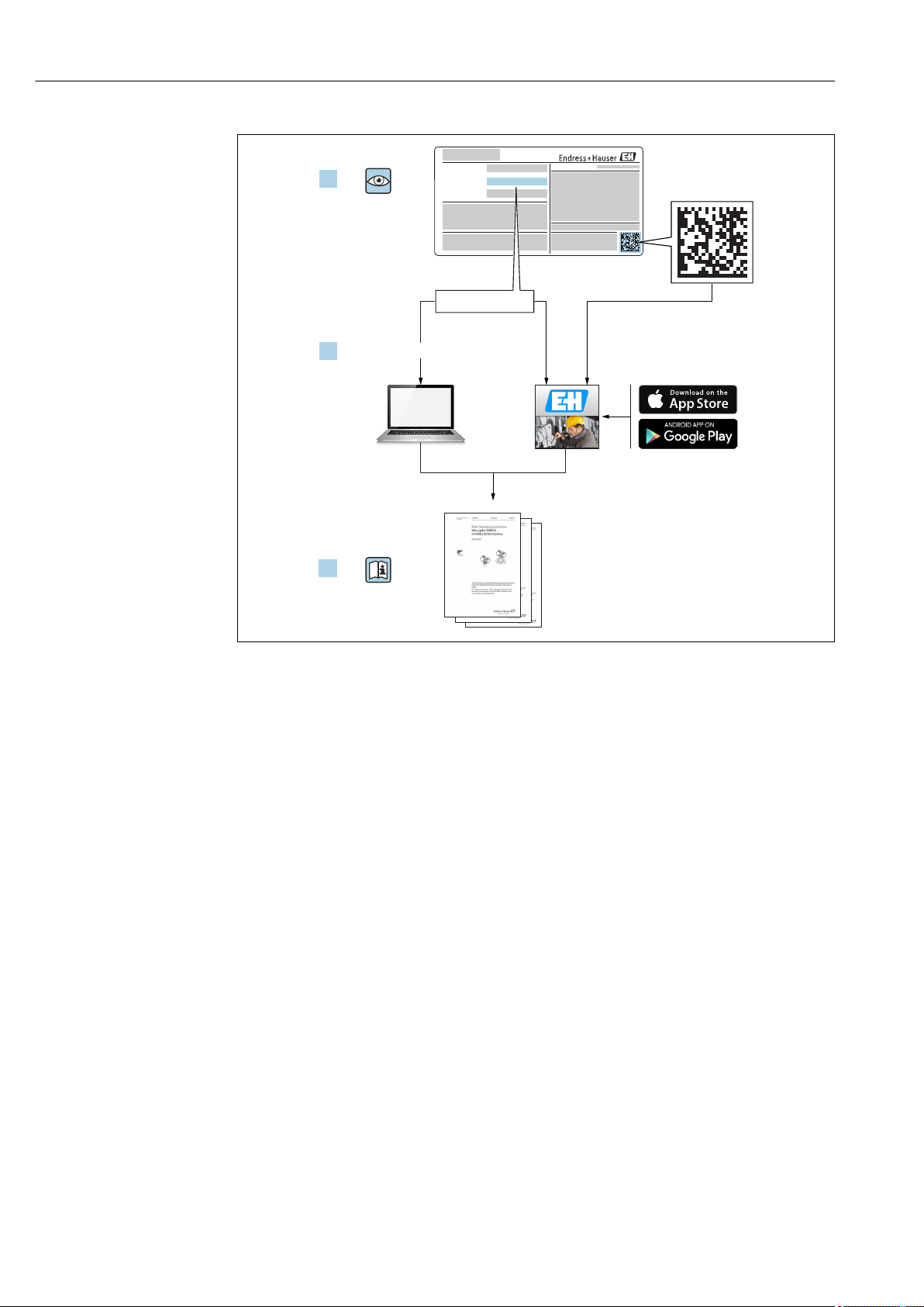
www.endress.com/deviceviewer
Endress+Hauser
Operations App
XXXXXXXXXXXX
XXXXX-XXXXXX
XXX.XXXX.XX
Serial number
1.
3.
2.
A0023555
2 Endress+Hauser
Page 3

Table of contents
Table of contents
1 Important document information .... 6
1.1 Document function ..................... 6
1.2 Symbols .............................. 6
1.2.1 Safety symbols .................. 6
1.2.2 Electrical symbols ................ 6
1.2.3 Tool symbols .................... 7
1.2.4 Symbols for certain types of
information .................... 7
1.2.5 Symbols in graphics ............... 7
1.2.6 Symbols at the device ............. 8
1.3 Additional documentation ................ 8
1.3.1 Safety Instructions (XA) ............ 9
2 Basic safety instructions ........... 12
2.1 Requirements for the personnel ........... 12
2.2 Designated use ....................... 12
2.3 Workplace safety ...................... 13
2.4 Operational safety ..................... 13
2.5 Product safety ........................ 13
2.5.1 CE mark ...................... 13
2.5.2 EAC conformity ................. 13
3 Product description ................ 14
3.1 Product design ........................ 14
3.1.1 Micropilot FMR51 ............... 14
3.1.2 Micropilot FMR52 ............... 14
3.1.3 Electronics housing .............. 15
3.2 Registered trademarks .................. 16
6.4.2 Mesurement from the outside
through plastic walls (FMR50/
FMR51) ...................... 28
6.4.3 Horn antenna, flush mount
(FMR52) ...................... 29
6.5 Installation in stilling well ............... 30
6.5.1 Recommendations for the stilling
well ......................... 30
6.5.2 Examples for the construction of
stilling wells ................... 31
6.6 Installation in bypass ................... 32
6.6.1 Recommendations for the bypass
pipe ......................... 32
6.6.2 Example for the construction of a
bypass ....................... 33
6.7 Vessels with heat insulation .............. 34
6.8 Turning the transmitter housing .......... 34
6.9 Turning the display module .............. 35
6.10 Post-installation check .................. 35
7 Electrical connection .............. 36
7.1 Connection conditions .................. 36
7.1.1 Terminal assignment ............. 36
7.1.2 Cable specification ............... 37
7.1.3 Device plug connectors ........... 38
7.1.4 Supply voltage .................. 39
7.1.5 Overvoltage protection ........... 39
7.2 Connecting the device .................. 40
7.2.1 Pluggable spring-force terminals .... 41
7.3 Post-connection check .................. 41
4 Incoming acceptance and product
identification ..................... 17
4.1 Incoming acceptance ................... 17
4.2 Product identification .................. 17
4.2.1 Nameplate .................... 18
5 Storage, Transport ................ 19
5.1 Storage conditions ..................... 19
5.2 Transport product to the measuring point .... 19
6 Installation ....................... 20
6.1 Installation conditions .................. 20
6.1.1 Mounting position ............... 20
6.1.2 Vessel installations .............. 21
6.1.3 Reduction of interference echoes .... 21
6.1.4 Measurement in a plastic vessel ..... 22
6.1.5 Optimization options ............. 22
6.1.6 Beam angle .................... 23
6.2 Measuring conditions .................. 24
6.3 Mounting cladded flanges ............... 25
6.4 Installation in vessel (free space) .......... 26
6.4.1 Horn antenna (FMR51) ........... 26
8 Operation options ................. 43
8.1 Overview ............................ 43
8.1.1 Local operation ................. 43
8.1.2 Operation with remote display and
operating module FHX50 .......... 44
8.1.3 Remote operation ............... 44
8.2 Structure and function of the operating
menu .............................. 46
8.2.1 Structure of the operating menu .... 46
8.2.2 User roles and related access
authorization .................. 47
8.2.3 Write protection via access code ..... 48
8.2.4 Disabling write protection via access
code ......................... 49
8.2.5 Deactivation of the write protection
via access code ................. 49
8.2.6 Write protection via write protection
switch ........................ 50
8.2.7 Enabling and disabling the keypad
lock ......................... 52
8.3 Display and operating module ............ 53
8.3.1 Display appearance .............. 53
8.3.2 Operating elements .............. 56
Endress+Hauser 3
Page 4

Table of contents
8.3.3 Entering numbers and text ........ 57
8.3.4 Opening the context menu ......... 59
8.3.5 Envelope curve on the display and
operating module ............... 60
9 Integration into a FOUNDATION
Fieldbus network .................. 61
9.1 Device Description (DD) ................. 61
9.2 Integration into the FOUNDATION Fieldbus
network ............................ 61
9.3 Device identification and addressing ........ 61
9.4 Block model .......................... 63
9.4.1 Blocks of the device software ....... 63
9.4.2 Block configuration when device is
delivered ...................... 64
9.5 Assignment of the measured values
(CHANNEL) in an AI Block ............... 64
9.6 Index tables of Endress+Hauser parameters .. 64
9.6.1 Setup Transducer Block ........... 65
9.6.2 Advanced Setup Transducer Block ... 65
9.6.3 Display Transducer Block .......... 66
9.6.4 Diagnostic Transducer Block ....... 67
9.6.5 Expert Configuration Transducer
Block ........................ 68
9.6.6 Expert Information Transducer
Block ........................ 70
9.6.7 Service Sensor Transducer Block .... 70
9.6.8 Service Information Transducer
Block ........................ 71
9.6.9 Advanced Diagnostics Transducer
Block ........................ 71
9.7 Methods ............................ 72
10 Commissioning via wizard ......... 73
11 Commissioning via operating
menu ............................. 74
11.1 Installation and function check ............ 74
11.2 Setting the operating language ............ 74
11.3 Configuration of a level measurement ...... 75
11.4 Recording the reference curve ............ 77
11.5 Configuration of the on-site display ........ 78
11.5.1 Factory settings of the on-site
display ....................... 78
11.5.2 Adjustment of the on-site display ... 78
11.6 Configuration management .............. 79
11.7 Protection of the settings against
unauthorized changes .................. 80
12 Commissioning (block-based
operation) ........................ 81
12.1 Function check ....................... 81
12.2 Block configuration .................... 81
12.2.1 Preparatory steps ............... 81
12.2.2 Configuring the Resource Block ..... 81
12.2.3 Configuring the Transducer Blocks ... 81
12.2.4 Configuring the Analog Input
Blocks ........................ 82
12.2.5 Additional configuration .......... 82
12.3 Scaling of the measured value in an AI Block .. 82
12.4 Language selection .................... 83
12.5 Configuration of a level measurement ...... 84
12.6 Configuration of the on-site display ........ 85
12.6.1 Factory settings of the on-site
display for level measurements ..... 85
12.7 Configuration management .............. 85
12.8 Configuration of the event behavior
according to the FOUNDATION Fieldbus
specification FF912 .................... 87
12.8.1 Groups of events ................ 88
12.8.2 Allocation parameters ............ 90
12.8.3 Configurable area ............... 93
12.8.4 Transmission of the event meassages
to the bus ..................... 94
12.9 Protection of the settings against
unauthorized changes .................. 94
13 Diagnostics and troubleshooting ... 95
13.1 General trouble shooting ................ 95
13.1.1 General errors .................. 95
13.1.2 Parametrization errors ........... 95
13.2 Diagnostic information on local display ...... 97
13.2.1 Diagnostic message .............. 97
13.2.2 Calling up remedial measures ...... 99
13.3 Diagnostic event in the operating tool ...... 100
13.4 Diagnostic messages in the DIAGNOSTIC
Transducer Block (TRDDIAG) ............ 100
13.5 Diagnostic list ....................... 100
13.6 Overview of diagnostic events ........... 101
13.7 Event logbook ....................... 102
13.7.1 Event history .................. 102
13.7.2 Filtering the event logbook ....... 103
13.7.3 Overview of information events .... 103
13.8 Firmware history ..................... 104
14 Maintenance .................... 105
14.1 Exterior cleaning ..................... 105
14.2 Replacing seals ...................... 105
15 Repairs .......................... 106
15.1 General information on repairs ........... 106
15.1.1 Repair concept ................ 106
15.1.2 Repairs to Ex-approved devices .... 106
15.1.3 Replacement of an electronics
module ...................... 106
15.1.4 Replacement of a device ......... 106
15.2 Spare parts ......................... 107
15.3 Return ............................. 107
15.4 Disposal ........................... 107
4 Endress+Hauser
Page 5

16 Accessories ...................... 108
16.1 Device-specific accessories .............. 108
16.1.1 Weather protection cover ........ 108
16.1.2 Remote display FHX50 .......... 109
16.1.3 Horn protection for horn antenna .. 110
16.1.4 Horn protection for horn antenna
with variable antenna extension ... 111
16.1.5 Overvoltage protection .......... 112
16.1.6 Gas-tight feedthrough ........... 112
16.2 Communication-specific accessories ....... 113
16.3 Service-specific accessories .............. 113
16.4 System components ................... 113
17 Operating menu .................. 114
17.1 Overview of the operating menu (display
module) ........................... 114
17.2 Overview of the operating menu (operating
tool) .............................. 120
17.3 "Setup" menu ........................ 126
17.3.1 "Mapping" wizard ............... 133
17.3.2 "Analog input 1 to 5" submenu ..... 134
17.3.3 "Advanced setup" submenu ........ 136
17.4 "Diagnostics" menu .................... 174
17.4.1 "Diagnostic list" submenu ......... 176
17.4.2 "Event logbook" submenu ......... 177
17.4.3 "Device information" submenu ..... 178
17.4.4 "Measured values" submenu ....... 180
17.4.5 "Analog input 1 to 5" submenu ..... 181
17.4.6 "Data logging" submenu .......... 183
17.4.7 "Simulation" submenu ........... 186
17.4.8 "Device check" submenu .......... 191
17.4.9 "Heartbeat" submenu ............ 193
Table of contents
Index ................................. 194
Endress+Hauser 5
Page 6
Important document information Micropilot FMR51, FMR52 FOUNDATION Fieldbus
DANGER
WARNING
CAUTION
NOTICE
1 Important document information
1.1 Document function
These Operating Instructions contain all the information that is required in various phases
of the life cycle of the device: from product identification, incoming acceptance and
storage, to mounting, connection, operation and commissioning through to
troubleshooting, maintenance and disposal.
1.2 Symbols
1.2.1 Safety symbols
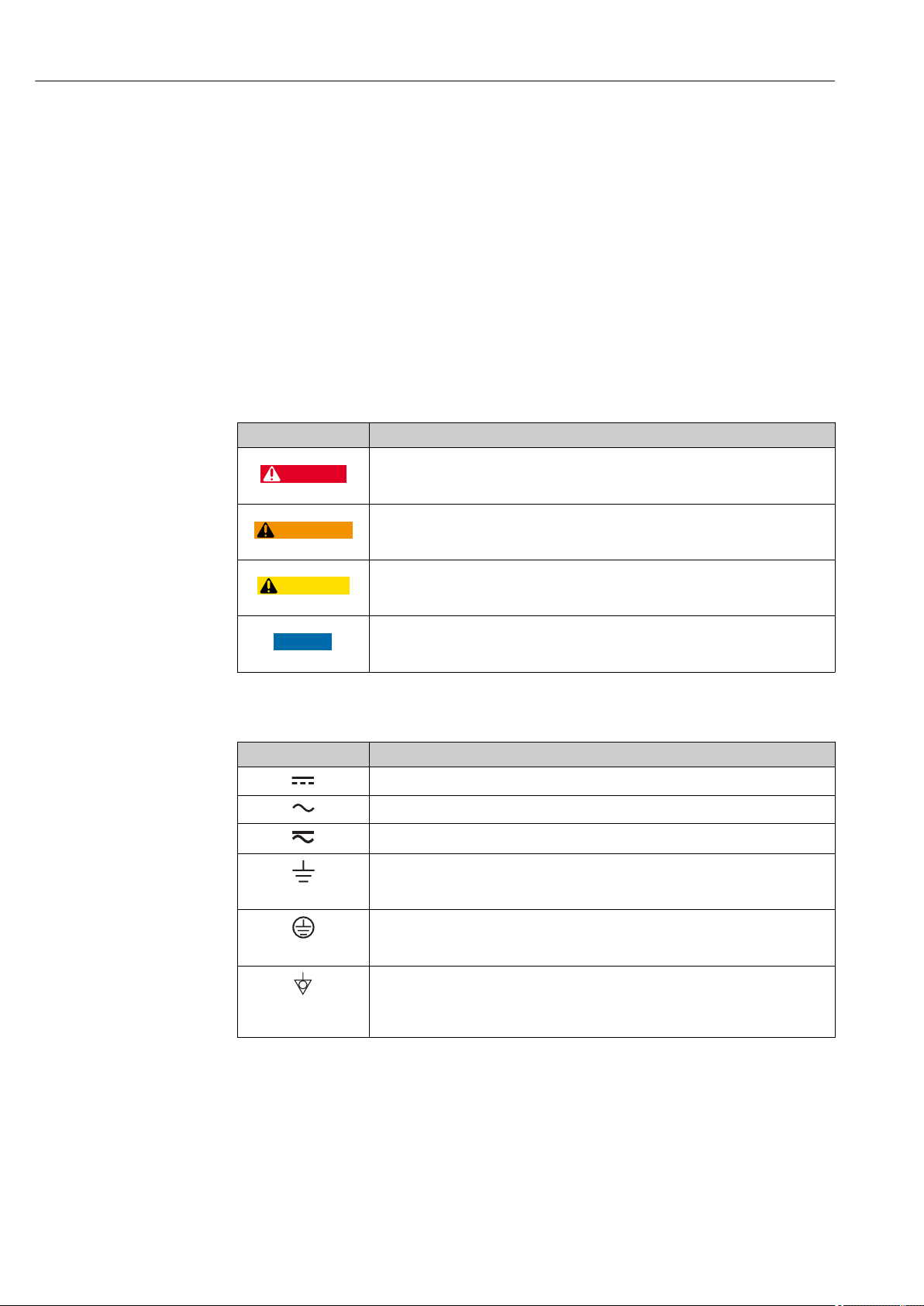
Symbol Meaning
DANGER!
This symbol alerts you to a dangerous situation. Failure to avoid this situation will
result in serious or fatal injury.
WARNING!
This symbol alerts you to a dangerous situation. Failure to avoid this situation can
result in serious or fatal injury.
CAUTION!
This symbol alerts you to a dangerous situation. Failure to avoid this situation can
result in minor or medium injury.
NOTE!
This symbol contains information on procedures and other facts which do not result in
personal injury.
1.2.2 Electrical symbols
Symbol Meaning
Direct current
Alternating current
Direct current and alternating current
Ground connection
A grounded terminal which, as far as the operator is concerned, is grounded via a
grounding system.
Protective ground connection
A terminal which must be connected to ground prior to establishing any other
connections.
Equipotential connection
A connection that has to be connected to the plant grounding system: This may be a
potential equalization line or a star grounding system depending on national or
company codes of practice.
6 Endress+Hauser
Page 7
Micropilot FMR51, FMR52 FOUNDATION Fieldbus Important document information
A
1.
1.
1.2.3 Tool symbols
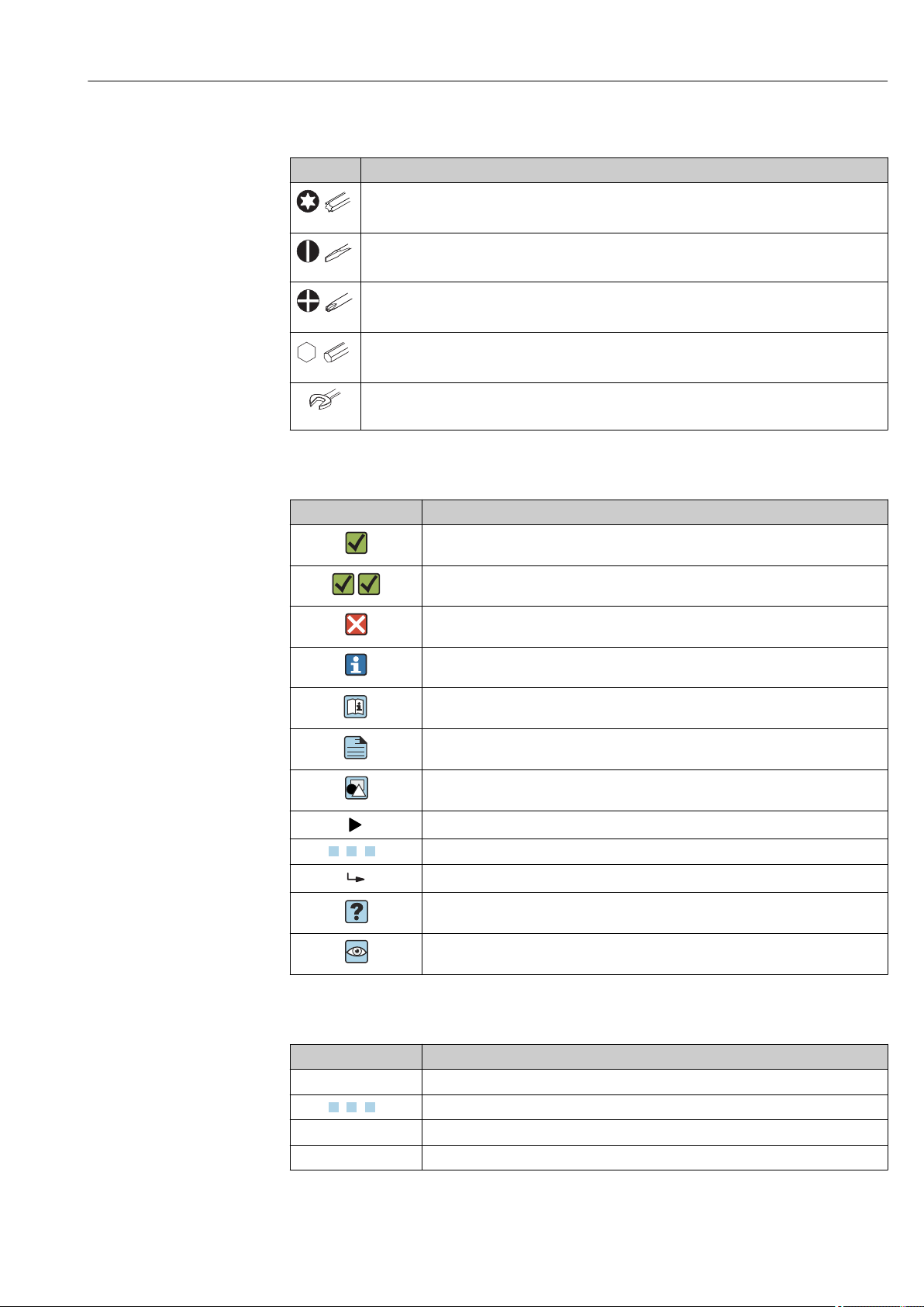
Symbol Meaning
Torx screwdriver
A0013442
Flat blade screwdriver
A0011220
Cross-head screwdriver
A0011219
Allen key
A0011221
Hexagon wrench
A0011222
1.2.4 Symbols for certain types of information
Symbol Meaning
Permitted
Procedures, processes or actions that are permitted.
Preferred
Procedures, processes or actions that are preferred.
Forbidden
Procedures, processes or actions that are forbidden.
Tip
Indicates additional information.
Reference to documentation
Reference to page
Reference to graphic
Notice or individual step to be observed
, 2., 3.… Series of steps
Result of a step
Help in the event of a problem
Visual inspection
1.2.5 Symbols in graphics
Symbol Meaning
1, 2, 3 ... Item numbers
, 2., 3.… Series of steps
A, B, C, ... Views
A-A, B-B, C-C, ... Sections
Endress+Hauser 7
Page 8
Important document information Micropilot FMR51, FMR52 FOUNDATION Fieldbus
-
.
Symbol Meaning
Hazardous area
Indicates a hazardous area.
Safe area (non-hazardous area)
Indicates the non-hazardous area.
1.2.6 Symbols at the device
Symbol Meaning
Safety instructions
Observe the safety instructions contained in the associated Operating Instructions.
Temperature resistance of the connection cables
Specifies the minimum value of the temperature resistance of the connection cables.
1.3 Additional documentation
Document Purpose and content of the document
Technical Information
TI01040F (FMR51, FMR52)
Brief Operating Instructions
KA01125F (FMR51/FMR52,
FOUNDATION Fieldbus)
Description of Device Parameters
GP01017F (FMR5x, FOUNDATION
Fieldbus)
Special documentation
SD01087F
Special documentation
SD01870F
Planning aid for your device
The document contains all the technical data on the device and provides
an overview of the accessories and other products that can be ordered for
the device.
Guide that takes you quickly to the 1st measured value
The Brief Operating Instructions contain all the essential information
from incoming acceptance to initial commissioning.
Reference for your parameters
The document provides a detailed explanation of each individual
parameter in the operating menu. The description is aimed at those who
work with the device over the entire life cycle and perform specific
configurations.
Functional Safety Manual
The document is part of the Operating Instructions and serves as a
reference for application-specific parameters and notes.
Manual for Heartbeat Verification and Heartbeat Monitoring
The document contains descriptions of the additonal parameters and
technical data which are available with the Heartbeat Verification and
Heartbeat Monitoring application packages.
For an overview of the scope of the associated Technical Documentation, refer to the
following:
• The W@M Device Viewer : Enter the serial number from the nameplate
(www.endress.com/deviceviewer)
• The Endress+Hauser Operations App: Enter the serial number from the nameplate
or scan the 2-D matrix code (QR code) on the nameplate.
8 Endress+Hauser
Page 9

Micropilot FMR51, FMR52 FOUNDATION Fieldbus Important document information
1.3.1 Safety Instructions (XA)
Depending on the approval, the following Safety Instructions (XA) are supplied with the
device. They are an integral part of the Operating Instructions.
Feature
010
BA ATEX: II 1 G Ex ia IIC T6-T1 Ga • FMR51
BB ATEX: II 1/2 G Ex ia IIC T6-T1 Ga/Gb • FMR51
BC ATEX: II 1/2 G Ex d [ia] IIC T6-T1 Ga/Gb • FMR51
BD ATEX: II 1/2/3 G Ex ic [ia Ga] IIC T6-T1
BG ATEX: II 3 G Ex nA IIC T6-T1 Gc • FMR51
BH ATEX: II 3 G Ex ic IIC T6-T1 Gc • FMR51
BL ATEX: II 1/2/3 G Ex nA [ia Ga] IIC T6-T1
B2 ATEX: II 1/2 G Ex ia IIC T6-T1 Ga/Gb
B3 ATEX: II 1/2 G Ex d [ia] IIC T6-T1 Ga/Gb
B4 ATEX:II 1/2 G Ex ia IIC T6-T1 Ga/Gb
CD CSA C/US DIP Cl.II,III Div.1 Gr.E-G FMR51 XA01113F XA01113F XA01113F XA01115F XA01113F
C2 CSA C/US IS Cl.I,II,III Div.1 Gr.A-G, NI Cl.1 Div.
C3 CSA C/US XP Cl.I,II,III Div.1 Gr.A-G, NI Cl.1
FB FM IS Cl.I,II,III Div.1 Gr.A-G, AEx ia, NI Cl.1
FD FM XP Cl.I,II,III Div.1 Gr.A-G, AEx d, NI Cl.1
FE FM DIP Cl.II,III Div.1 Gr.E-G FMR51 XA01117F XA01117F XA01117F XA01119F XA01117F
IA IECEx: Ex ia IIC T6-T1 Ga • FMR51
IH IECEx: Ex ic IIC T6-T1 Gc • FMR51
Approval Available for Feature 020 "Power Supply; Output"
• FMR52
• FMR52
• FMR52
• FMR51
Ga/Gb/Gc
Ga/Gb/Gc
ATEX: II 1/2 D Ex ia IIIC Txx°C Da/Db
ATEX: II 1/2 D Ex ta IIIC Txx°C Da/Db
ATEX: II 1/2 G Ex d [ia] IIC T6-T1 Ga/Gb
2, Ex ia
Div.2, Ex d
Div.2
Div.2
IB IECEx: Ex ia IIC T6-T1 Ga/Gb • FMR51
IC IECEx: Ex d [ia] IIC T6-T1 Ga/Gb • FMR51
ID IECEx: Ex ic [ia Ga] IIC T6-T1 Ga/Gb/Gc • FMR51
IG IECEx: Ex nA IIC T6-T1 Gc • FMR51
IL IECEx: Ex nA [ia Ga] IIC T6-T1 Ga/Gb/Gc • FMR51
I2 IECEx: Ex ia IIC T6-T1 Ga/Gb
IECEx: Ex ia IIIC Txx°C Da/Db
• FMR52
• FMR52
• FMR52
• FMR51
• FMR52
• FMR51
• FMR52
• FMR51
• FMR52
• FMR51
• FMR52
• FMR51
• FMR52
• FMR51
• FMR52
• FMR51
• FMR52
• FMR51
• FMR52
• FMR52
• FMR52
• FMR52
• FMR52
• FMR52
• FMR52
• FMR52
• FMR51
• FMR52
1)
A
XA00677F XA00677F XA00677F XA00685F -
XA00677F XA00677F XA00677F XA00685F -
XA00680F XA00680F XA00680F XA00688F XA00680F
XA00678F XA00678F XA00678F XA00686F XA00678F
XA00679F XA00679F XA00679F XA00687F XA00679F
XA00679F XA00679F XA00679F XA00687F XA00679F
XA00678F XA00678F XA00678F XA00686F XA00678F
XA00683F XA00683F XA00683F XA00691F -
XA00684F XA00684F XA00684F XA00692F XA00684F
XA00681F XA00681F XA00681F XA00689F -
XA01112F XA01112F XA01112F XA01114F -
XA01113F XA01113F XA01113F XA01115F XA01113F
XA01116F XA01116F XA01116F XA01118F -
XA01117F XA01117F XA01117F XA01119F XA01117F
XA00677F XA00677F XA00677F XA00685F -
XA00677F XA00677F XA00677F XA00685F -
XA00680F XA00680F XA00680F XA00688F XA00680F
XA00678F XA00678F XA00678F XA00686F XA00678F
XA00679F XA00679F XA00679F XA00687F XA00679F
XA00679F XA00679F XA00679F XA00687F XA00679F
XA00678F XA00678F XA00678F XA00686F XA00678F
XA00683F XA00683F XA00683F XA00691F -
2)
B
3)
C
4)/G 5)
E
6)/L 7)
K
Endress+Hauser 9
Page 10

Important document information Micropilot FMR51, FMR52 FOUNDATION Fieldbus
Feature
Approval Available for Feature 020 "Power Supply; Output"
010
I3 IECEx: Ex d [ia] IIC T6-T1 Ga/Gb
IEXEx: Ex ta IIIC Txx°C Da/Db
I4 IECEx: Ex ia IIC T6-T1 Ga/Gb
IECEx: Ex d [ia] IIC T6-T1 Ga/Gb
• FMR51
• FMR52
• FMR51
• FMR52
KA KC Ex ia IIC T6 Ga • FMR51
• FMR52
KB KC Ex ia IIC T6 Ga/Gb • FMR51
• FMR52
KC KC Ex d[ia] IIC T6 • FMR51
• FMR52
MA INMETRO: Ex ia IIC T6 Ga • FMR51
• FMR52
MC INMETRO: Ex d[ia] IIC T6 Ga/Gb • FMR51
• FMR52
MH INMETRO: Ex ic IIC T6 Gc • FMR51
• FMR52
NA NEPSI Ex ia IIC T6 Ga • FMR51
• FMR52
NB NEPSI Ex ia IIC T6 Ga/Gb • FMR51
• FMR52
NC NEPSI Ex d[ia] IIC T6 Ga/Gb • FMR51
• FMR52
NG NEPSI Ex nA II T6 Gc • FMR51
• FMR52
NH NEPSI Ex ic IIC T6 Gc • FMR51
• FMR52
N2 NEPSI Ex ia IIC T6 Ga/Gb, Ex iaD 20/21 T85…
90oC
N3 NEPSI Ex d[ia] IIC T6 Ga/Gb, DIP A20/21
T85…90oC IP66
• FMR51
• FMR52
• FMR51
• FMR52
8A FM/CSA IS+XP Cl.I,II,III Div.1 Gr.A-G • FMR51
• FMR52
1)
A
2)
B
3)
C
4)/G 5)
E
6)/L 7)
K
XA00684F XA00684F XA00684F XA00692F XA00684F
XA00681F XA00681F XA00681F XA00689F -
XA01045F XA01045F XA01045F XA01047F -
XA01045F XA01045F XA01045F XA01047F -
XA01046F XA01046F XA01046F XA01048F XA01046F
XA01286F XA01287F XA01288F XA01296F -
XA01292F XA01292F XA01293F XA01298F XA01294F
XA01289F XA01290F XA01291F XA01297F -
XA01199F XA01199F XA01199F XA01208F -
XA01199F XA01199F XA01199F XA01208F -
XA01202F XA01202F XA01202F XA01211F XA01202F
XA01201F XA01201F XA01201F XA01210F XA01201F
XA01201F XA01201F XA01201F XA01210F XA01201F
XA01205F XA01205F XA01205F XA01214F -
XA01206F XA01206F XA01206F XA01215F XA01206F
• XA01112F
• XA01113F
• XA01116F
• XA01117F
• XA01112F
• XA01113F
• XA01116F
• XA01117F
• XA01112F
• XA01113F
• XA01116F
• XA01117F
• XA01114F
• XA01115F
• XA01118F
• XA01119F
-
1) 2-wire; 4-20mA HART
2) 2-wire; 4-20mA HART, switch output
3) 2-wire; 4-20mA HART, 4-20mA
4) 2-wire; FOUNDATION Fieldbus, switch output
5) 2-wire; PROFIBUS PA, switch output
6) 4-wire 90-253VAC; 4-20mA HART
7) 4-wire 10.4-48VDC; 4-20mA HART
For certified devices the relevant Safety Instructions (XA) are indicated on the
nameplate.
10 Endress+Hauser
Page 11

Micropilot FMR51, FMR52 FOUNDATION Fieldbus Important document information
If the device is prepared for the remote display FHX50 (product structure: feature 030:
Display, Operation", option L or M), the Ex marking of some certificates changes according
to the following table
1)
:
Feature 010
("Approval")
BG L or M ATEX II 3G Ex nA [ia Ga] IIC T6-T1 Gc
BH L or M ATEX II 3G Ex ic [ia Ga] IIC T6-T1 Gc
B3 L or M ATEX II 1/2G Ex d [ia] IIC T6-T1 Ga/Gb,
IG L or M IECEx Ex nA [ia Ga] IIC T6-T1 Gc
IH L or M IECEx Ex ic [ia Ga] IIC T6-T1 Gc
I3 L or M IECEx Ex d [ia] IIC T6-T1 Ga/Gb,
MH L or M Ex ic [ia Ga] IIC T6 Gc
NG L or M NEPSI Ex nA [ia Ga] IIC T6-T1 Gc
NH L or M NEPSI Ex ic [ia Ga] IIC T6-T1 Gc
N3 L or M NEPSI Ex d [ia] IIC T6-T1 Ga/Gb, DIP A20/21 [ia D] TA, Txx°C
Feature 030 ("Display,
Operation")
Ex marking
ATEX II 1/2D Ex ta [ia Db] IIIC Txx°C Da/Db
IECEx Ex ta [ia Db] IIIC Txx°C Da/Db
IP6X
1) The marking of certificates not mentioned in this table are not affected by the FHX50.
Endress+Hauser 11
Page 12

Basic safety instructions Micropilot FMR51, FMR52 FOUNDATION Fieldbus
2 Basic safety instructions
2.1 Requirements for the personnel
The personnel for installation, commissioning, diagnostics and maintenance must fulfill
the following requirements:
Trained, qualified specialists must have a relevant qualification for this specific function
‣
and task.
Are authorized by the plant owner/operator.
‣
Are familiar with federal/national regulations.
‣
Before starting work, read and understand the instructions in the manual and
‣
supplementary documentation as well as the certificates (depending on the
application).
Follow instructions and comply with basic conditions.
‣
The operating personnel must fulfill the following requirements:
Are instructed and authorized according to the requirements of the task by the facility's
‣
owner-operator.
Follow the instructions in this manual.
‣
2.2 Designated use
Application and measured materials
The measuring device described in these Operating Instructions is intended for the
continuous, contactless level measurement of liquids, pastes and sludge. The device can
also be freely mounted outside closed metal vessels (e.g. above basins, open channels or
open piles) because of its operating frequency of about 26 GHz, a maximum radiated
pulsed power of 5.7 mW and an average power output of 0.015 mW (for the version with
advanced dynamics: maximum pulse power: 23.3 mW; average power: 0.076 mW).
Operation is completely harmless to humans and animals.
Observing the limit values specified in the "Technical data" and listed in the Operating
Instructions and supplementary documentation, the measuring device may be used for the
following measurements only:
Measured process variables: level, distance, signal strength
‣
Calculated process variables: Volume or mass in arbitrarily shaped vessels; flow
‣
through measuring weirs or flumes (calculated from the level by the linearization
functionality)
To ensure that the measuring device remains in proper condition for the operation time:
Use the measuring device only for measured materials against which the process-
‣
wetted materials are adequately resistant.
Observe the limit values in "Technical data".
‣
Incorrect use
The manufacturer is not liable for damage caused by improper or non-designated use.
Verification for borderline cases:
For special measured materials and cleaning agents, Endress+Hauser is glad to provide
‣
assistance in verifying the corrosion resistance of wetted materials, but does not accept
any warranty or liability.
Residual risk
The electronics housing and its built-in components such as display module, main
electronics module and I/O electronics module may heat to 80 °C (176 °F) during operation
through heat transfer from the process as well as power dissipation within the electronics.
During operation the sensor may assume a temperature near the temperature of the
measured material.
12 Endress+Hauser
Page 13

Micropilot FMR51, FMR52 FOUNDATION Fieldbus Basic safety instructions
Danger of burns due to heated surfaces!
For high process temperatures: Install protection against contact in order to prevent
‣
burns.
2.3 Workplace safety
For work on and with the device:
Wear the required personal protective equipment according to federal/national
‣
regulations.
2.4 Operational safety
Risk of injury.
Operate the device in proper technical condition and fail-safe condition only.
‣
The operator is responsible for interference-free operation of the device.
‣
Conversions to the device
Unauthorized modifications to the device are not permitted and can lead to unforeseeable
dangers.
If, despite this, modifications are required, consult with the manufacturer.
‣
Repair
To ensure continued operational safety and reliability,
Carry out repairs on the device only if they are expressly permitted.
‣
Observe federal/national regulations pertaining to repair of an electrical device.
‣
Use original spare parts and accessories from the manufacturer only.
‣
Hazardous area
To eliminate a danger for persons or for the facility when the device is used in the
hazardous area (e.g. explosion protection, pressure vessel safety):
Based on the nameplate, check whether the ordered device is permitted for the
‣
intended use in the hazardous area.
Observe the specifications in the separate supplementary documentation that is an
‣
integral part of these Instructions.
2.5 Product safety
This measuring device is designed in accordance with good engineering practice to meet
state-of-the-art safety requirements, has been tested, and left the factory in a condition in
which it is safe to operate. It meets general safety standards and legal requirements.
2.5.1 CE mark
The measuring system meets the legal requirements of the applicable EC guidelines. These
are listed in the corresponding EC Declaration of Conformity together with the standards
applied.
Endress+Hauser confirms successful testing of the device by affixing to it the CE mark.
2.5.2 EAC conformity
The measuring system meets the legal requirements of the applicable EAC guidelines.
These are listed in the corresponding EAC Declaration of Conformity together with the
standards applied.
Endress+Hauser confirms successful testing of the device by affixing to it the EAC mark.
Endress+Hauser 13
Page 14
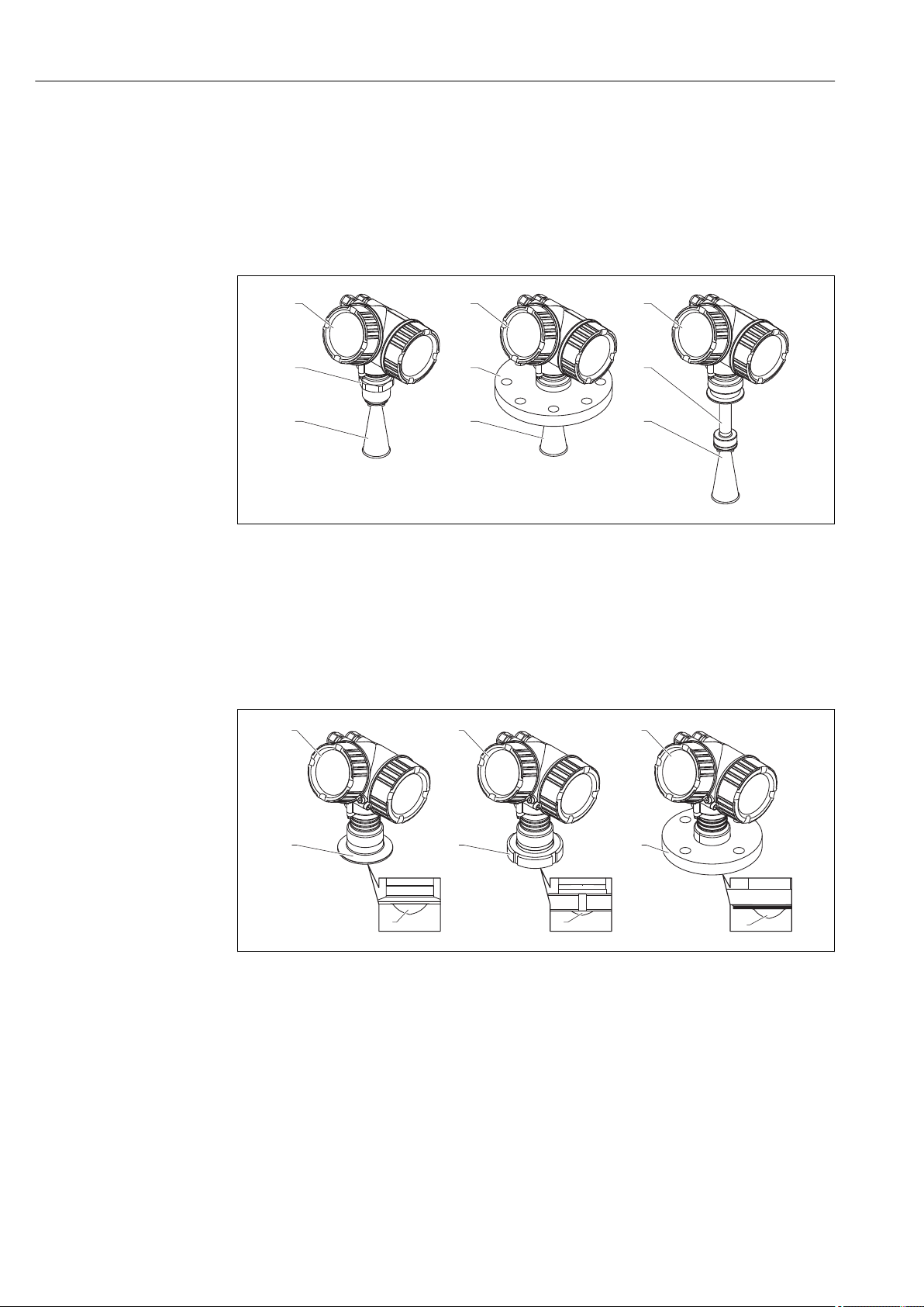
Product description Micropilot FMR51, FMR52 FOUNDATION Fieldbus
11
2
3 3 3
54
1
1 1 1
2 3 5
4
4
4
3 Product description
3.1 Product design
3.1.1 Micropilot FMR51
1 Design of the Micropilot FMR51 (26 GHz)
1 Electronics housing
2 Process connection (Thread)
3 Horn antenna
4 Flange
5 Antenna extension
3.1.2 Micropilot FMR52
2 Design of the Micropilot FMR52 (26 GHz)
1 Electronics housing
2 Tri-Clamp process connection
3 Dairy coupling
4 PTFE cladding
5 Flange
A0016818
A0016788
14 Endress+Hauser
Page 15
Micropilot FMR51, FMR52 FOUNDATION Fieldbus Product description
Esc
–
+
E
1
2
3
4
5
6
9
7
8
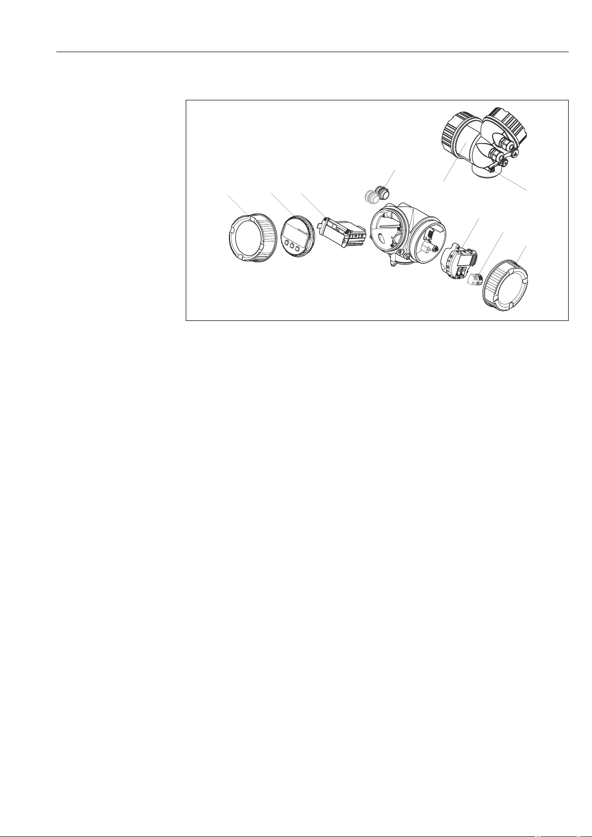
3.1.3 Electronics housing
A0012422
3 Design of the electronics housing
1 Electronics compartment cover
2 Display module
3 Main electronics module
4 Cable glands (1 or 2, depending on instrument version)
5 Nameplate
6 I/O electronics module
7 Terminals (pluggable spring terminals)
8 Connection compartment cover
9 Grounding terminal
Endress+Hauser 15
Page 16

Product description Micropilot FMR51, FMR52 FOUNDATION Fieldbus
3.2 Registered trademarks
FOUNDATIONTM Fieldbus
Registered trademark of the FieldComm Group, Austin, Texas, USA
KALREZ®, VITON
Registered trademark of DuPont Performance Elastomers L.L.C., Wilmington, USA
TEFLON
®
Registered trademark of E.I. DuPont de Nemours & Co., Wilmington, USA
TRI CLAMP
Registered trademark of Alfa Laval Inc., Kenosha, USA
®
®
16 Endress+Hauser
Page 17
Micropilot FMR51, FMR52 FOUNDATION Fieldbus Incoming acceptance and product identification
DELIVERYNOTE
1 = 2
DELIVERYNOTE
Madein Germany, 79689 Maulburg
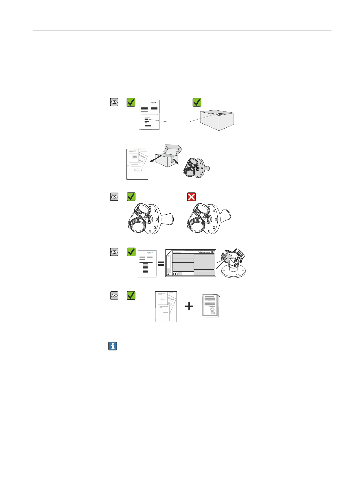
4 Incoming acceptance and product
identification
4.1 Incoming acceptance
Are the order codes on the delivery
A0015502
A0022480
A0016871
note (1) and the product sticker (2)
identical?
Are the goods undamaged?
A0015502
A0016872
Do the nameplate data match the
A0015502
A0022491
ordering information on the delivery
note?
Is the DVD with the operating tool
A0015502
present?
If required (see nameplate): Are the
Safety Instructions (XA) present?
A0022494
If one of these conditions is not satisfied, contact your Endress+Hauser Sales Center.
4.2 Product identification
The following options are available for identification of the measuring device:
• Nameplate specifications
• Extended order code with breakdown of the device features on the delivery note
• Enter serial numbers from nameplates in W@M Device Viewer
( www.endress.com/deviceviewer ): All information about the measuring device is
displayed.
• Enter the serial number from the nameplates into the Endress+Hauser Operations App
or scan the 2-D matrix code (QR code) on the nameplate with the Endress+Hauser
Operations App: all the information for the measuring device is displayed.
Endress+Hauser 17
Page 18
Incoming acceptance and product identification Micropilot FMR51, FMR52 FOUNDATION Fieldbus
20
21
22
24
25
23
26
1
2
3
4
5
6
7
8
9
10
19
18
17
16
15
14
Ext. ord. cd.:
Order code:
Ser. no.:
T max =
p
LN =
Mat.:
Date:
FW:
Dev.Rev.:
Ta:
if modification
see sep. label
X =
MWP:
12
11
47 (1.85)
92 (3.62)
mm (in)
13
For an overview of the scope of the associated Technical Documentation, refer to the
following:
• The W@M Device Viewer: Enter the serial number from the nameplate
(www.endress.com/deviceviewer)
• The Endress+Hauser Operations App: Enter the serial number from the nameplate or
scan the 2-D matrix code (QR code) on the nameplate.
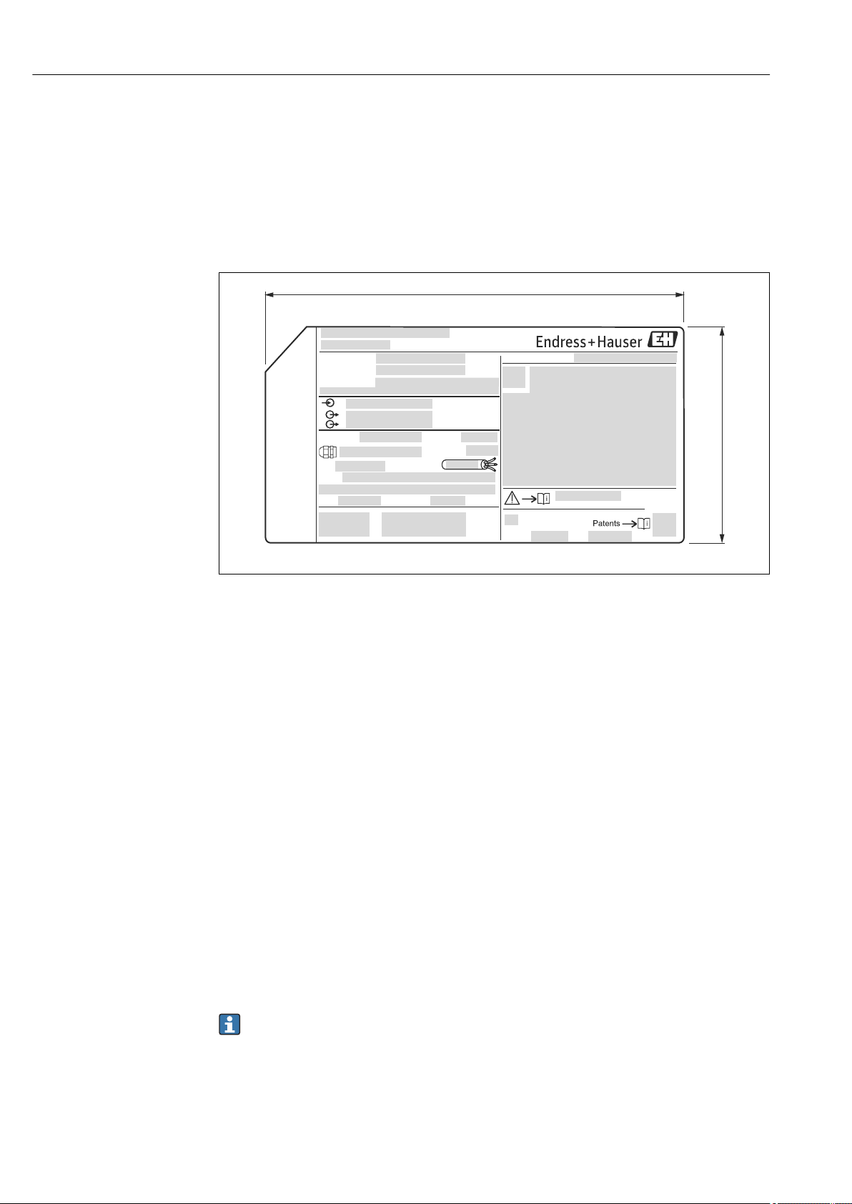
4.2.1 Nameplate
A0019444
4 Nameplate of the Micropilot
1 Device name
2 Address of manufacturer
3 Order code
4 Serial number (Ser. no.)
5 Extended order code (Ext. ord. cd.)
6 Process pressure
7 Antenna length (only for FMR51 with antenna extension)
8 Certificate symbol
9 Certificate and approval relevant data
10 Degree of protection: e.g. IP, NEMA
11 Document number of the Safety Instructions: e.g. XA, ZD, ZE
12 Data Matrix Code
13 Modification mark
14 Manufacturing date: year-month
15 Temperature resistance of the cable
16 Geräterevision (Dev.Rev.)
17 Additional information about the device version (certificates, approvals, communication): e.g. SIL, PROFIBUS
18 Firmware version (FW)
19 CE mark, C-Tick
20 Profibus PA: Profil-Version; FOUNDATION Fieldbus: Device ID
21 Material in contact with process
22 Permitted ambient temperature (Ta)
23 Size of the thread of the cable glands
24 Maximum process temperature
25 Signal outputs
26 Operating voltage
18 Endress+Hauser
Only 33 digits of the extended order code can be indicated on the nameplate. If the
extended order code exceeds 33 digits, the rest will not be shown. However, the
complete extended order code can be viewed in the operating menu of the device:
Extended order code 1 to 3 parameter
Page 19
Micropilot FMR51, FMR52 FOUNDATION Fieldbus Storage, Transport
5 Storage, Transport
5.1 Storage conditions
• Permitted storage temperature: –40 to +80 °C (–40 to +176 °F)
• Use the original packaging.
5.2 Transport product to the measuring point
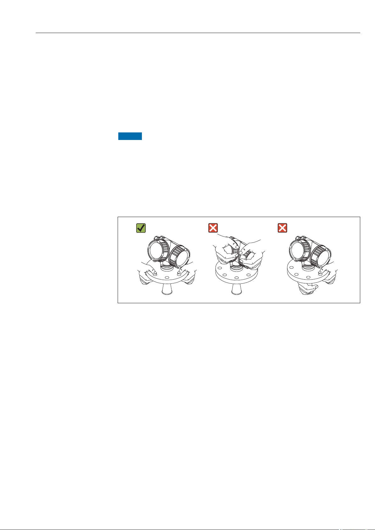
NOTICE
Housing or antenna horn may be damaged or break away.
Risk of injury!
Transport the measuring device to the measuring point in its original packaging or at
‣
the process connection.
Do not fasten lifting devices (hoisting slings, lifting eyes etc.) at the housing or the
‣
antenna horn but at the process connection. Take into account the mass center of the
device in order to avoid unintended tilting.
Comply with the safety instructions, transport conditions for devices over 18kg
‣
(39.6lbs) (IEC61010).
A0016875
Endress+Hauser 19
Page 20
Installation Micropilot FMR51, FMR52 FOUNDATION Fieldbus
A
1 2
3
6 Installation
6.1 Installation conditions
6.1.1 Mounting position
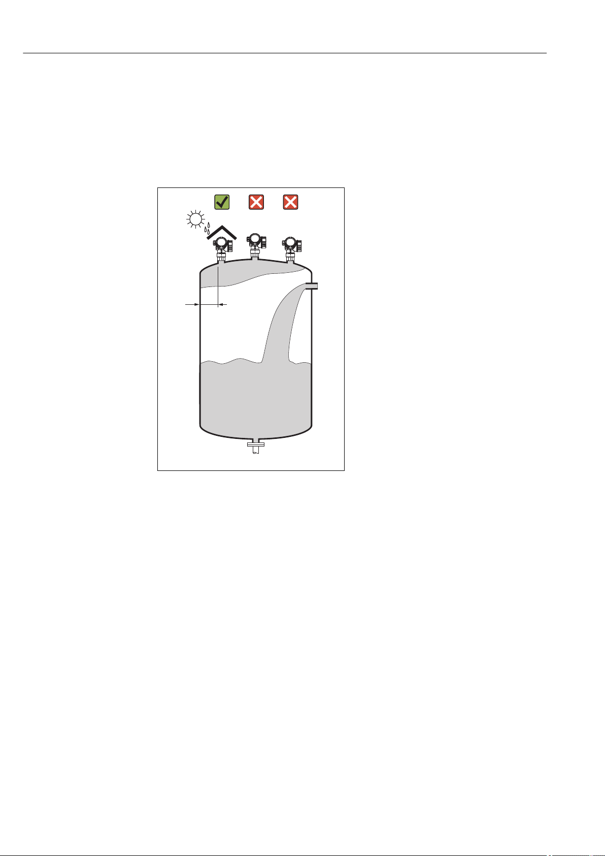
• Recommended distance A from wall to
outer edge of nozzle: ~ 1/6 of tank
diameter.
Nevertheless the device should not be
installed closer than 15 cm (5.91 in) to
the tank wall.
• Not in the center (2), as interference can
cause signal loss.
• Not above the fill stream (3).
• It is recommended to us a weather
protection cover (1) in order to protect
the device from direct sun or rain.
A0016882
20 Endress+Hauser
Page 21
Micropilot FMR51, FMR52 FOUNDATION Fieldbus Installation
6.1.2 Vessel installations
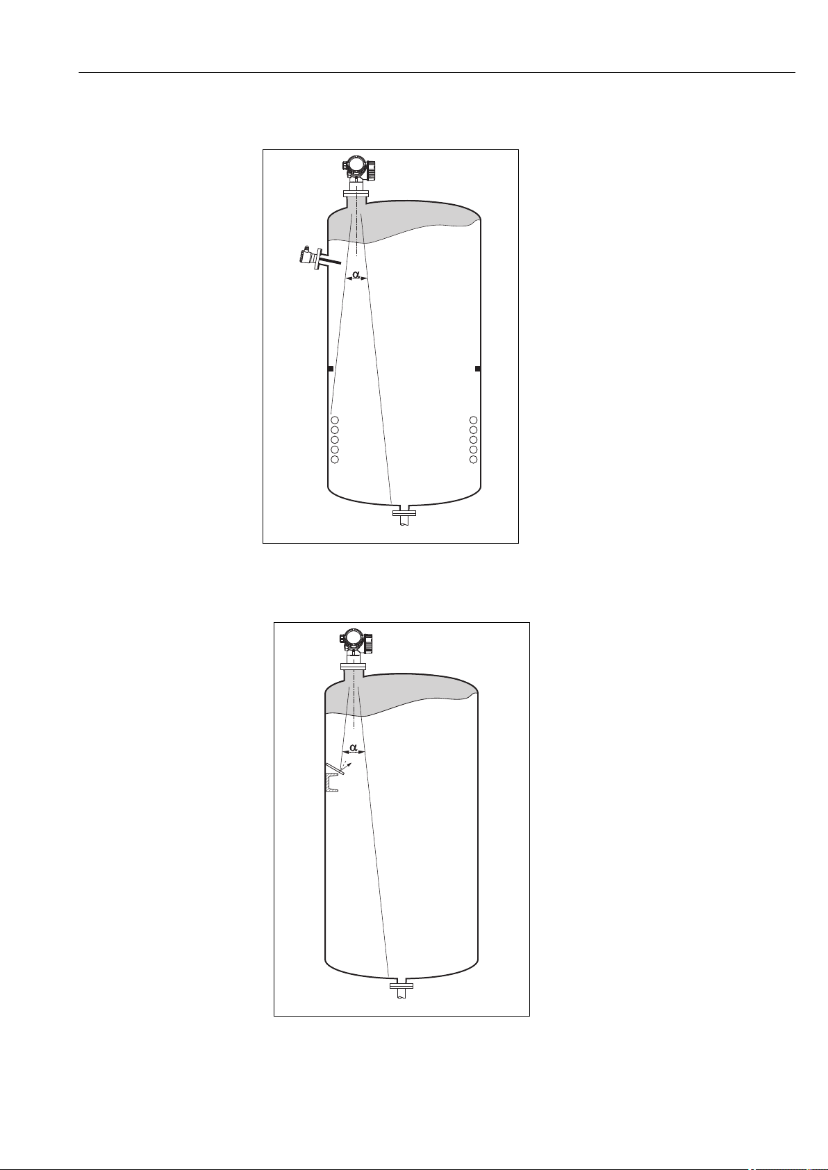
Avoid any installations (point level
switches, temperature sensors, braces,
vacuum rings, heating coils, baffles etc.)
inside the signal beam. Take into account
the beam angle → 23.
A0018944
6.1.3 Reduction of interference echoes
Metallic screens mounted at a slope
spread the radar signal and can,
therefore, reduce interference echoes.
A0016890
Endress+Hauser 21
Page 22
Installation Micropilot FMR51, FMR52 FOUNDATION Fieldbus
2
3
1
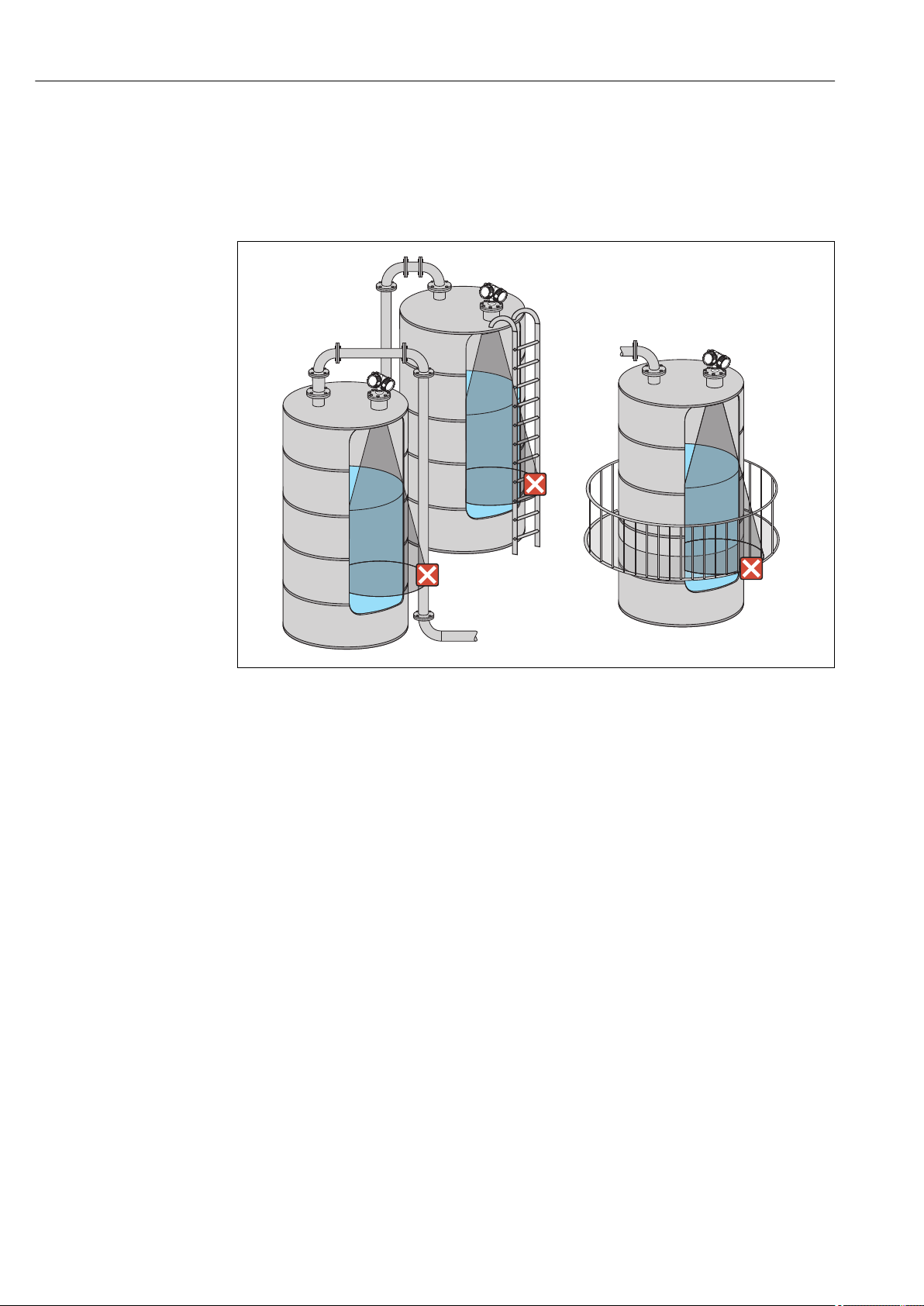
6.1.4 Measurement in a plastic vessel
If the outer wall of the vessel is made of a non-conductive material (e.g. GRP), microwaves
can also be reflected off interfering installations outside the vessel (e.g. metallic pipes (1),
ladders (2), grates (3), ...). Therefore, there should be no such interfering installations in
the signal beam. Please contact Endress+Hauser for further information.
6.1.5 Optimization options
• Antenna size
The bigger the antenna, the smaller the beam angle α and the fewer interference echoes
→ 23.
• Mapping
The measurement can be optimized by means of electronic suppression of interference
echoes.
See the Confirm distance parameter (→ 130) for details.
• Antenna alignment
Take into account the marker on the flange or threaded connection → 26
→ 29 .
• Stilling well
A stilling well can be applied to avoid interferences → 30.
• Metallic screens mounted at a slope
They spread the radar signals and can, therefore, reduce interference echoes.
A0017123
22 Endress+Hauser
Page 23
Micropilot FMR51, FMR52 FOUNDATION Fieldbus Installation
a
D
W
a
D
_
=
2
2
. .
tan
W
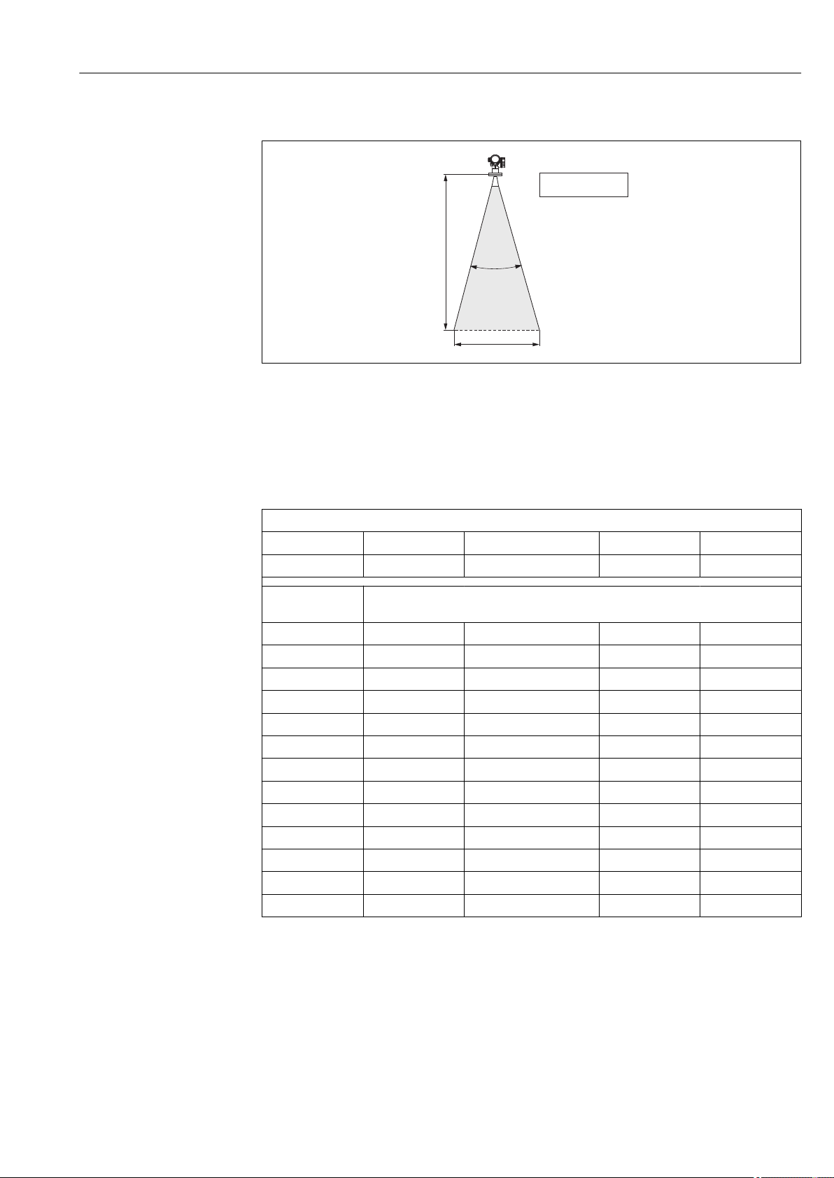
6.1.6 Beam angle
A0016891
5 Relationship between beam angle α, distance D and beamwidth diameter W
The beam angle is defined as the angle α where the energy density of the radar waves
reaches half the value of the maximum energy density (3-dB-width). Microwaves are also
emitted outside the signal beam and can be reflected off interfering installations.
Beam diameter W as a function of beam angle α and measuring distance D:
FMR51
Antenna size 40 mm (1½ in) 50 mm (2 in) 80 mm (3 in) 100 mm (4 in)
Beam angle α 23° 18° 10° 8°
Measuring
distance (D)
3 m (9.8 ft) 1.22 m (4 ft) 0.95 m (3.1 ft) 0.53 m (1.7 ft) 0.42 m (1.4 ft)
6 m (20 ft) 2.44 m (8 ft) 1.9 m (6.2 ft) 1.05 m (3.4 ft) 0.84 m (2.8 ft)
9 m (30 ft) 3.66 m (12 ft) 2.85 m (9.4 ft) 1.58 m (5.2 ft) 1.26 m (4.1 ft)
12 m (39 ft) 4.88 m (16 ft) 3.80 m (12 ft) 2.1 m (6.9 ft) 1.68 m (5.5 ft)
15 m (49 ft) 6.1 m (20 ft) 4.75 m (16 ft) 2.63 m (8.6 ft) 2.10 m (6.9 ft)
20 m (66 ft) 8.14 m (27 ft) 6.34 m (21 ft) 3.50 m (11 ft) 2.80 m (9.2 ft)
25 m (82 ft) 10.17 m (33 ft) 7.92 m (26 ft) 4.37 m (14 ft) 3.50 m (11 ft)
30 m (98 ft) - 9.50 m (31 ft) 5.25 m (17 ft) 4.20 m (14 ft)
35 m (115 ft) - 11.09 m (36 ft) 6.12 m (20 ft) 4.89 m (16 ft)
40 m (131 ft) - 12.67 m (42 ft) 7.00 m (23 ft) 5.59 m (18 ft)
45 m (148 ft) - - 7.87 m (26 ft) 6.29 m (21 ft)
60 m (197 ft) - - 10.50 m (34 ft) 8.39 m (28 ft)
70 m (230 ft) - - - 9.79 m (32 ft)
Beamwidth diameter W
Endress+Hauser 23
Page 24

Installation Micropilot FMR51, FMR52 FOUNDATION Fieldbus
FMR52
Antenna size 50 mm (2 in) 80 mm (3 in)
Beam angle α 18° 10°
Measuring distance (D) Beamwidth diameter W
3 m (9.8 ft) 0.95 m (3.1 ft) 0.53 m (1.7 ft)
6 m (20 ft) 1.9 m (6.2 ft) 1.05 m (3.4 ft)
9 m (30 ft) 2.85 m (9.4 ft) 1.58 m (5.2 ft)
12 m (39 ft) 3.80 m (12 ft) 2.1 m (6.9 ft)
15 m (49 ft) 4.75 m (16 ft) 2.63 m (8.6 ft)
20 m (66 ft) 6.34 m (21 ft) 3.50 m (11 ft)
25 m (82 ft) 7.92 m (26 ft) 4.37 m (14 ft)
30 m (98 ft) 9.50 m (31 ft) 5.25 m (17 ft)
35 m (115 ft) 11.09 m (36 ft) 6.12 m (20 ft)
40 m (131 ft) 12.67 m (42 ft) 7.00 m (23 ft)
45 m (148 ft) - 7.87 m (26 ft)
60 m (197 ft) - 10.50 m (34 ft)
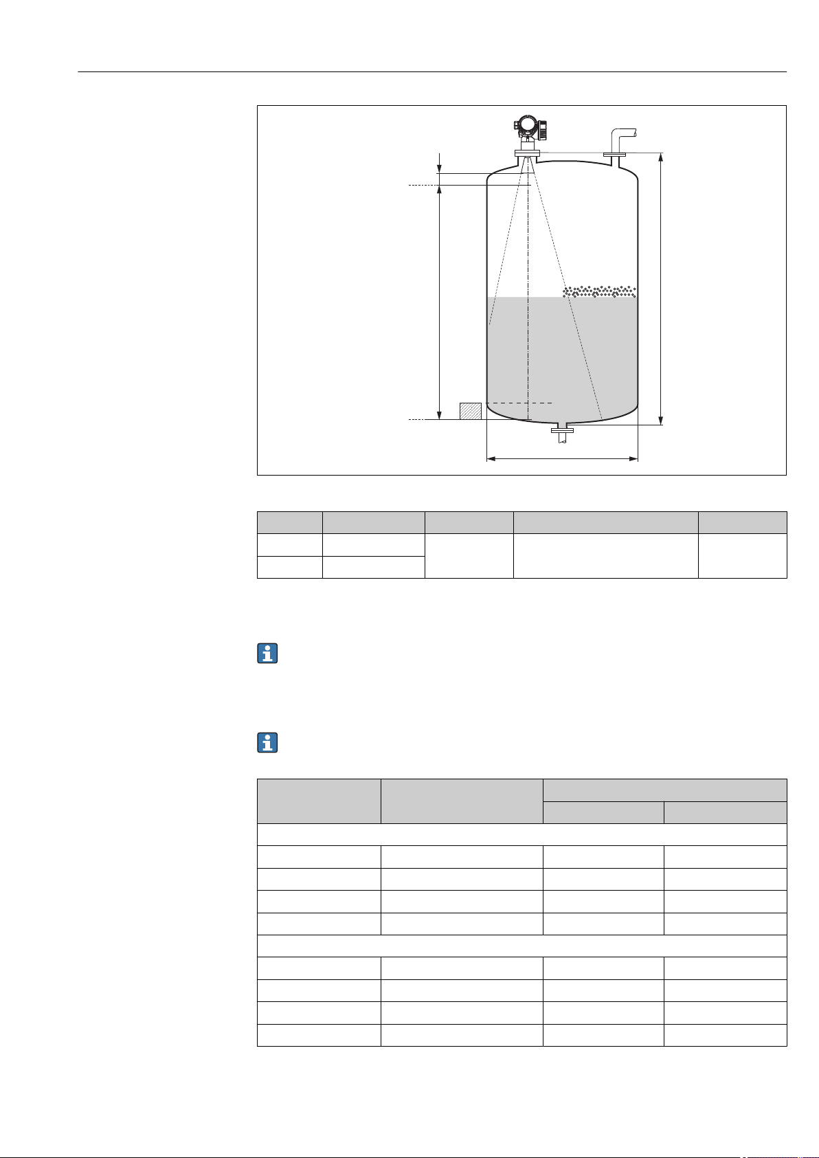
6.2 Measuring conditions
• In case of boiling surfaces, bubbling or tendency for foaming use FMR53 or FMR54.
Depending on its consistence, foam can either absorb microwaves or reflect them off the
foam surface. Measurement is possible under certain conditions. For FMR50, FMR51
and FMR52, the additional option "Advanced dynamics" is recommended in these cases
(feature 540: "Application Package", option EM).
• In case of heavy steam development or condensate, the maximum measuring range of
FMR50, FMR51 and FMR52 may decrease depending on density, temperature and
composition of the steam → use FMR53 or FMR54.
• For the measurement of absorbing gases such as ammonia NH3 or some
fluorocarbons
• The measuring range begins, where the beam hits the tank bottom. Particularly with
dish bottoms or conical outlets the level cannot be detected below this point.
• In stilling well applications, the electromagnetic waves do not propagate completely
outside the tube. It must be taken into account that the accuracy may be reduced in the
area C. In order to guarantee the required accuracy in these cases, it is recommended to
position the zero-point at a distance C above the end of the tube (see figure).
• In case of media with a low dielectric constant (εr = 1.5 to 4)
visible through the medium at low levels (low height C). Reduced accuracy has to be
expected in this range. If this is not acceptable, we recommend positioning the zero
point at a distance C (see figure) above the tank bottom in these applications.
• In principle it is possible to measure up to the tip of the antenna with FMR51, FMR53
and FMR54. However, due to considerations regarding corrosion and build-up, the end
of the measuring range should not be chosen any closer than A (see figure) to the tip of
the antenna.
• When using FMR54 with planar antenna, especially for media with low dielectric
constants, the end of the measuring range should not be closer than A: 1 m (3.28 ft) to
the flange.
• The smallest possible measuring range B depends on the antenna version (see figure).
• The tank height should be at least H (see table).
2)
, please use Levelflex or Micropilot FMR54 in a stilling well.
3)
the tank bottom can be
2) Affected compounds are e.g. R134a, R227, Dymel 152a.
3) Dielectric constants of important media commonly used in various industries are summarized in the DC manual (CP01076F) and in the Endress
+Hauser "DC Values App" (available for Android and iOS).
24 Endress+Hauser
Page 25
Micropilot FMR51, FMR52 FOUNDATION Fieldbus Installation
100%
0%
B
A
C
H
øD
A0018872
Device A [mm (in)] B [m (ft)] C [mm (in)] H [m (ft)]
FMR51 50(1.97)
FMR52 200(7.87)
> 0.2 (0.7) 50 to 250 (1.97 to 9.84) > 0.3 (1.0)
6.3 Mounting cladded flanges
• Use flange screws according to the number of flange holes.
• Tighten the screws with the required torque (see table).
• Retighten the screws after 24 hours or after the first temperature cycle.
• Depending on process pressure and process temperature check and retighten the
screws at regular intervals.
Usually, the PTFE flange cladding also serves as a seal between the nozzle and the
device flange.
Flange size Number of screws Recommended torque [Nm]
minimum maximum
EN
DN50/PN16 4 45 65
DN80/PN16 8 40 55
DN100/PN16 8 40 60
DN150/PN16 8 75 115
ASME
2"/150lbs 4 40 55
3"/150lbs 4 65 95
4"/150lbs 8 45 70
6"/150lbs 8 85 125
Endress+Hauser 25
Page 26
Installation Micropilot FMR51, FMR52 FOUNDATION Fieldbus
90°
90°
90°
90°
90°
90°
90°
90°
90°
90°
A
B
Flange size Number of screws Recommended torque [Nm]
minimum maximum
JIS
10K 50A 4 40 60
10K 80A 8 25 35
10K 100A 8 35 55
10K 100A 8 75 115
6.4 Installation in vessel (free space)
6.4.1 Horn antenna (FMR51)
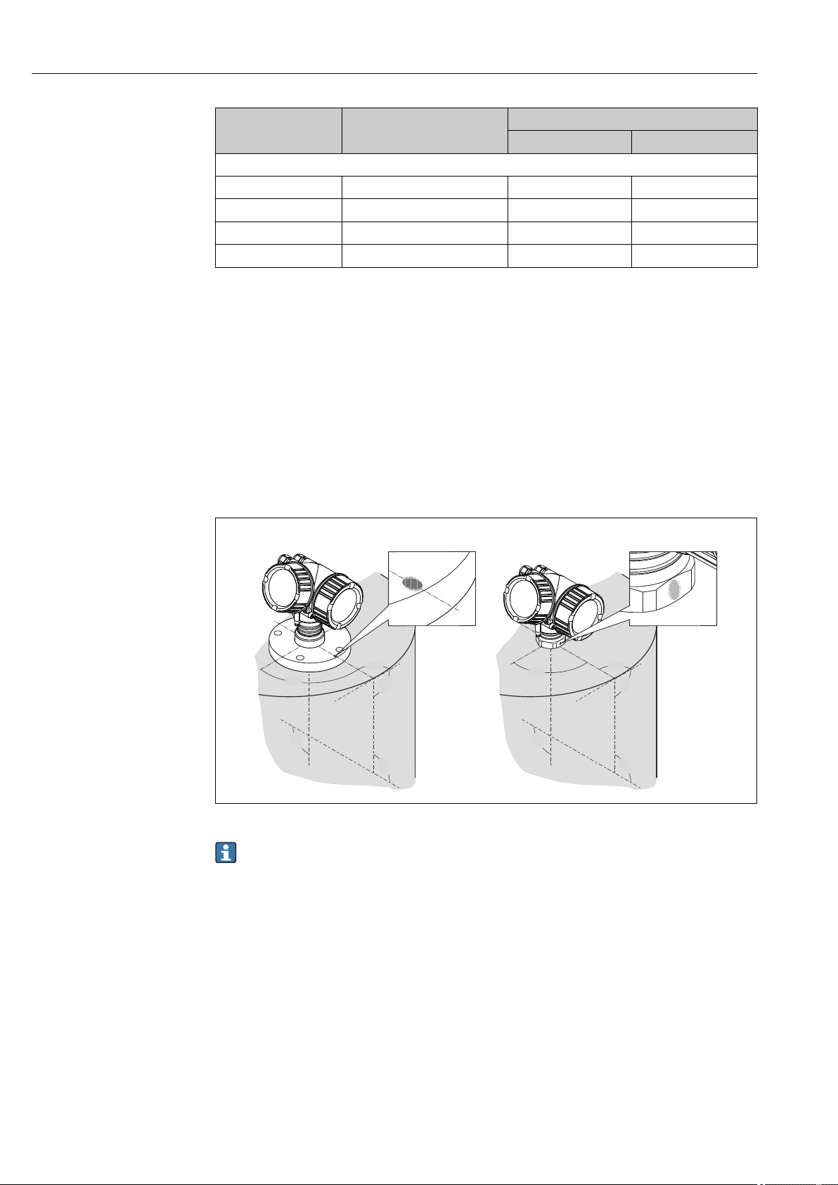
Alignment
• Align the antenna vertically to the product surface.
The maximum range may be reduced if the horn antenna is not vertically aligned.
• A marking at the flange (somewhere between the flange holes) or the boss enables
alignment of the antenna. This marking must be aligned towards the tank wall as well
as possible.
Depending on the device version the marking may be a circle or two short parallel
lines.
Nozzle mounting
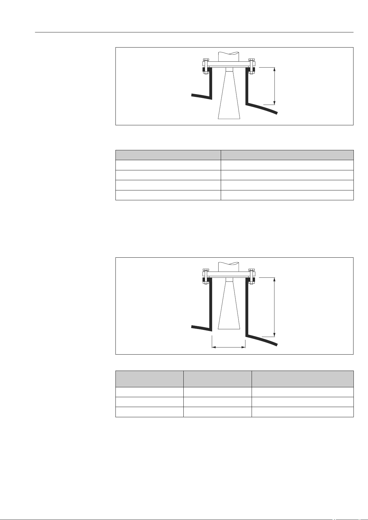
For optimum measurement, the tip of the antenna should extend below the nozzle.
Depending on the antenna size this is achieved by the following maximum nozzle heights:
26 Endress+Hauser
A0018974
Page 27
Micropilot FMR51, FMR52 FOUNDATION Fieldbus Installation
H
max
H
max
øD
A0016820
6 Nozzle height for horn antenna (FMR51)
Antenna
1)
Maximum nozzle height H
max
BA: Horn 40mm/1-1/2" 86 mm (3.39 in)
BB: Horn 50mm/2" 115 mm (4.53 in)
BC: Horn 80mm/3" 211 mm (8.31 in)
BD Horn 100mm/4" 282 mm (11.1 in)
1) Feature 070 of the product structure
Conditions for longer nozzles
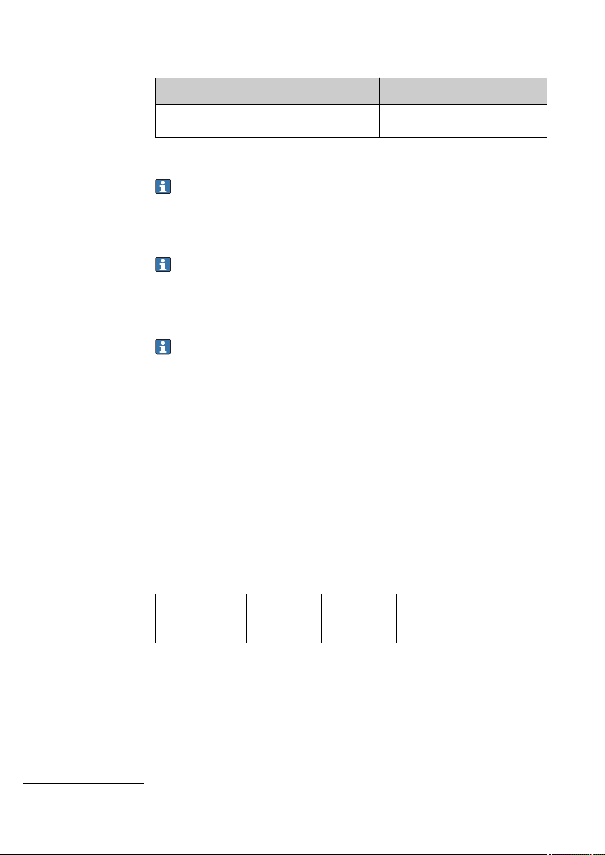
If the medium has good reflective properties, higher nozzles can be accepted. In this case
the maximum nozzle height, H
, is dependent on the nozzle diameter, D:
max
A0023611
Nozzle diameter D Maximum nozzle height
H
max
Recommended antenna
1)
40 mm (1.5 in) 100 mm (3.9 in) BA: Horn 40mm/1-1/2"
50 mm (2 in) 150 mm (5.9 in) BB: Horn 50mm/2"
80 mm (3 in) 250 mm (9.8 in) BC: Horn 80mm/3"
Endress+Hauser 27
Page 28
Installation Micropilot FMR51, FMR52 FOUNDATION Fieldbus
Nozzle diameter D Maximum nozzle height
H
max
100 mm (4 in) 500 mm (19.7 in) BD: Horn 100mm/4"
150 mm (6 in) 800 mm (31.5 in) BD: Horn 100mm/4"
1) Feature 070 of the product structure
Recommended antenna
1)
If the antenna doesn't extend below the nozzle, observe the following:
• The nozzle end must be smooth and free of burrs. If possible its edge should be
rounded.
• An interference echo suppression must be performed.
• Please contact Endress+Hauser for applications with higher nozzles than those
indicated in the table.
• For mounting in heigh nozzles the device is available in a version with an antenna
extension of up to 1 000 mm (39.4 in)
4)
• The antenna extension may cause interference echoes in the near range. In this
case it may occur that the maximum measurable level is reduced.
Threaded connection
For devices with a threaded connection it may be necessary - depending on the
antenna size - to unmount the horn before fastening the device and to mount it again
afterwards.
• Tighten with the hexagonal nut only.
• Tool : 55 mm hexagonal wrench
• Maximum permissible torque: 60 Nm (44 lbf ft)
6.4.2 Mesurement from the outside through plastic walls (FMR50/ FMR51)
• Dielectric constant of the medium: εr > 10
• If possible, use an antenna 100 mm (4 in).
• The distance from the lower edge of the antenna to the tank ceiling should be about
100 mm (4 in).
• If possible, avoid mounting locations where condensation or build-up might occur.
• In case of outdoor mounting, the space between antenna and vessel has to be protected
from the elements.
• Do not mount any potential reflectors (e.g. pipes) outside the tank in the signal beam.
Suitable thickness of the tank ceiling:
Penetrated material PE PTFE PP Perspex
DK / ε
r
Optimum thickness
1) Other possible values for the thickness are multiples of the values listed (e.g. for PE: 7,6 mm (0.3 in), 11,4
mm (0.45 in)
1)
2.3 2.1 2.3 3.1
3.8 mm (0.15 in) 4.0 mm (0.16 in) 3.8 mm (0.15 in) 3.3 mm (0.13 in)
4) Feature 610 "Accessory mounted" of the product structure.
28 Endress+Hauser
Page 29
Micropilot FMR51, FMR52 FOUNDATION Fieldbus Installation
90°
90°
90°
90°
90°
90°
90°
90°
90°
90°
A
B
H
max
6.4.3 Horn antenna, flush mount (FMR52)
Alignment
• Align the antenna vertically to the product surface.
The maximum range may be reduced if the horn antenna is not vertically aligned.
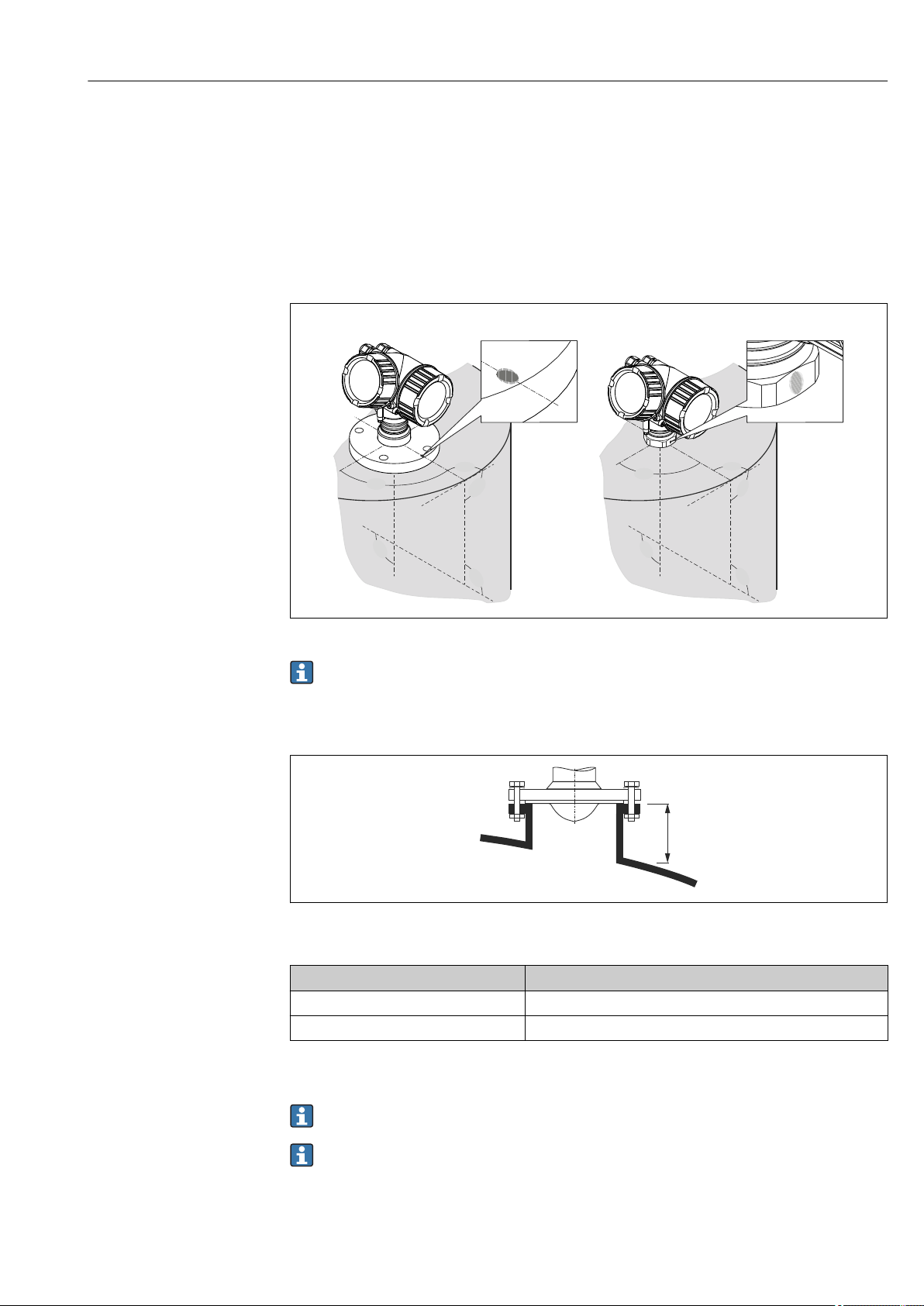
• A marking at the flange (somwhere between the flange holes) or the boss enables
alignment of the antenna. This marking must be aligned towards the tank wall as well
as possible.
A0018974
Depending on the device version the marking may be a circle or two short parallel
lines.
Nozzle mounting
A0016819
7 Nozzle height for horn antenna, flush mount (FMR52)
Antenna
BO: Horn 50mm/2" 500 mm (19.7 in)
BP: Horn 80mm/3" 500 mm (19.7 in)
1) Feature 070 of the product structure
1)
Maximum nozzle height H
max
Please contact Endress+Hauser for applications with higher nozzle.
• For flanges with PTFE cladding: Observe the notes on the mounting of cladded
flanges → 25.
• Usually, the PTFE flange cladding also serves as a seal between the nozzle and the
device flange.
Endress+Hauser 29
Page 30
Installation Micropilot FMR51, FMR52 FOUNDATION Fieldbus
1
90°
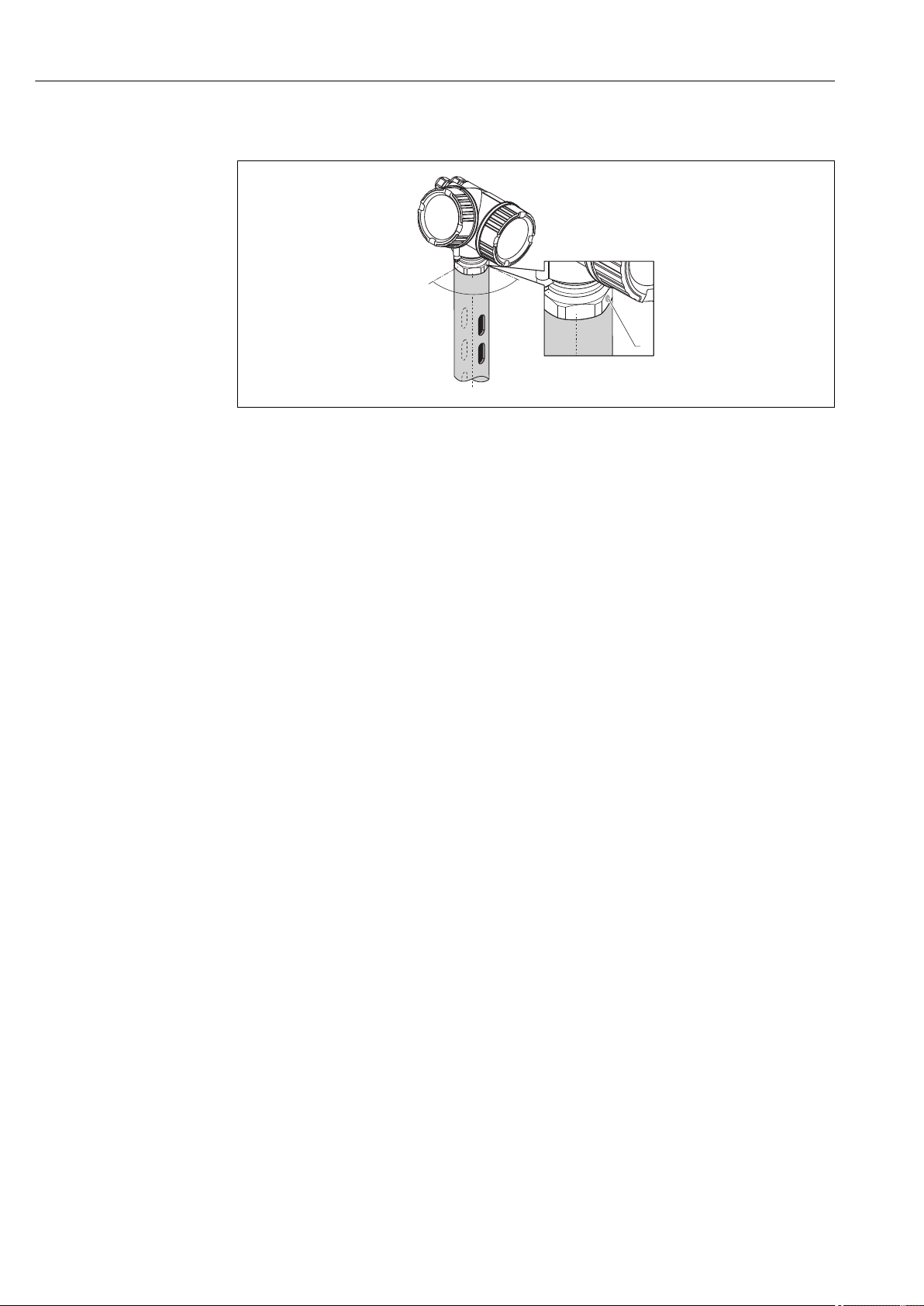
6.5 Installation in stilling well
A0016841
8 Installation in stilling well
1 Marking for antenna alignment
• For horn antenna: Align the marking towards the slots of the stilling well.
• Measurements can be performed through an open full bore ball valve without any
problems.
• After mounting, the housing can be turned 350° in order to facilitate access to the
display and the terminal compartment → 34.
6.5.1 Recommendations for the stilling well
• Metal (no enamel coating; plastic on request).
• Constant diameter.
• Diameter of stilling well not larger than antenna diameter.
• Diameter difference between horn antenna and inner diameter of the stilling well as
small as possible.
• Weld seam as smooth as possible and on the same axis as the slots.
• Slots offset 180° (not 90°).
• Slot width or diameter of holes max. 1/10 of pipe diameter, de-burred. Length and
number do not have any influence on the measurement.
• Select horn antenna as big as possible. For intermedaite sizes (e.g. 180 mm (7 in)) select
next larger antenna and adapt it mechanically (for horn antennas)
• At any transition (i.e. when using a ball valve or mending pipe segments), no gap may be
left exceeding 1 mm (0.04 in).
• The stilling well must be smooth on the inside (average roughness Rz ≤
6.3 μm (248 μin)). Use extruded or parallel welded metal pipe. An extension of the pipe
is possible with welded flanges or pipe sleeves. Flange and pipe have to be properly
aligned at the inside.
• Do not weld through the pipe wall. The inside of the stilling well must remain smooth. In
case of unintentional welding through the pipe, the weld seam and any unevenness on
the inside need to be carefully removed and smoothened. Otherwise, strong interference
echoes will be generated and material build-up will be promoted.
• In the case of smaller nominal widths flanges must be welded to the pipe such that they
allow for a correct orientation (marker aligned toward slots).
30 Endress+Hauser
Page 31
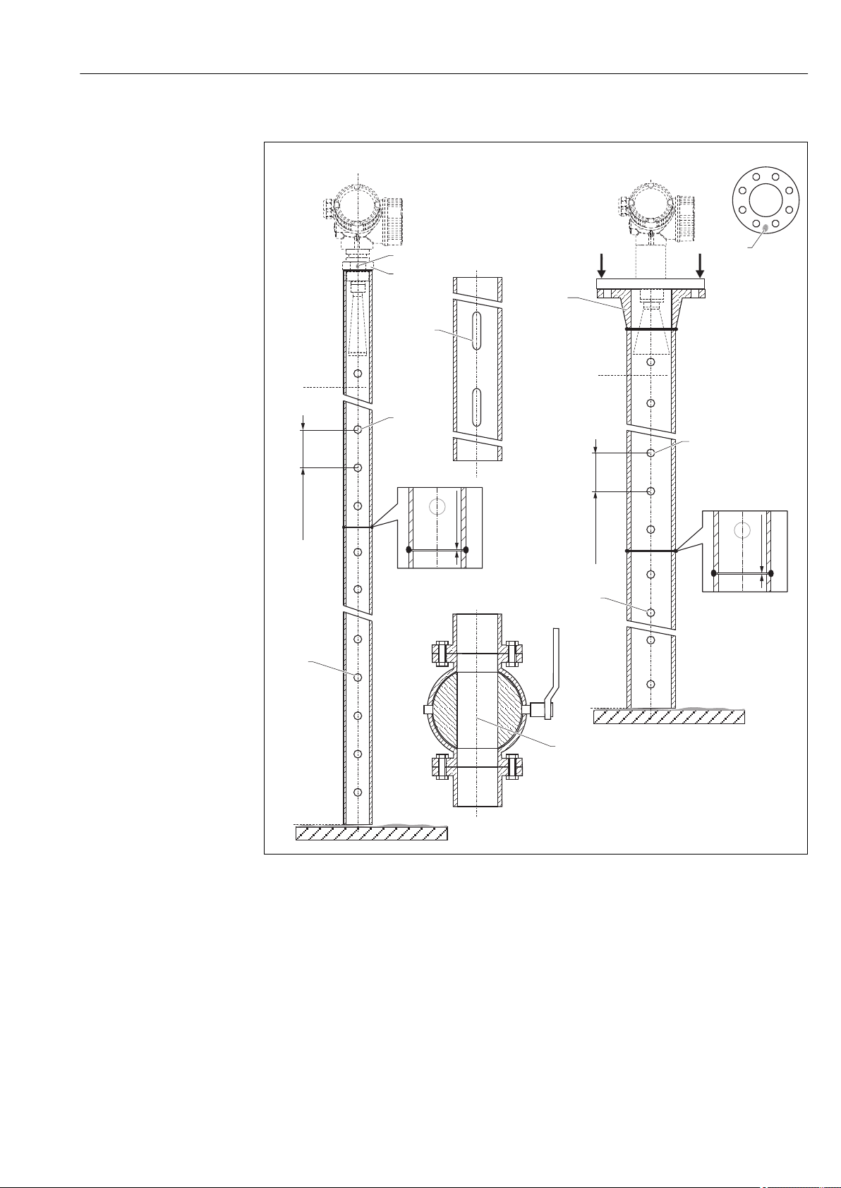
Micropilot FMR51, FMR52 FOUNDATION Fieldbus Installation
100%
0%
100%
0%
A
B
A A
A-A
150…500
(5.91...19.7)
150…500
(5.91...19.7)
mm (in)
2
1
4
4
C
D
5
6
6
7
1
3
1 (0.04)≤
1 (0.04)≤
6.5.2 Examples for the construction of stilling wells
A0019009
A Micropilot FMR50/FMR51: Horn 40mm(1½")
B Micropilot FMR50/FMR51/FMR52/FMR54: Horn 80mm(3")
C Stilling well with slots
D Full bore ball valve
1 Marking for axial alignment
2 Threaded connection
3 e.g. welding neck flange DIN2633
4 hole max. 1/10 stilling well
5 hole max. 1/10 stilling well; single sided or drilled through
6 Inside of holes deburred
7 Diameter of opening of ball valve must always be equivalent to pipe diameter; avoid edges and constrictions.
Endress+Hauser 31
Page 32
Installation Micropilot FMR51, FMR52 FOUNDATION Fieldbus
1
2
2
90°
90°
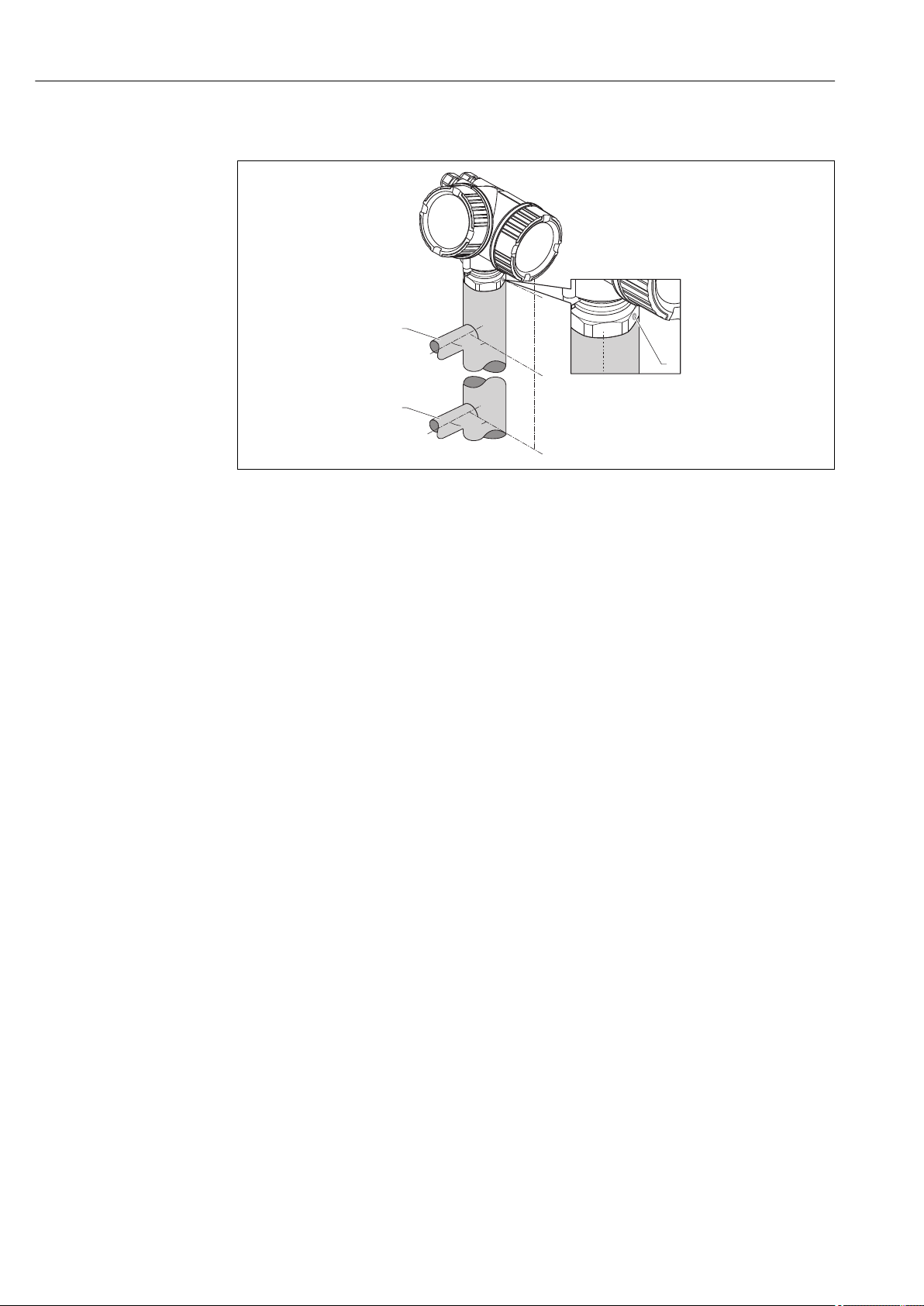
6.6 Installation in bypass
A0019446
9 Installation in bypass
1 Marking for antenna alignment
2 Tank connectors
• Alighn the marker perpendicular (90°) to the tank connectors.
• Measurements can be performed through an open full bore ball valve without any
problems.
• After mounting, the housing can be turned 350° in order to facilitate access to the
display and the terminal compartment → 34.
6.6.1 Recommendations for the bypass pipe
• Metal (no plastic or enamel coating).
• Constant diameter.
• Select horn antenna as big as possible. For intermediate sizes (e.g. 95 mm (3.5 in))
select next larger antenna and adapt it mechanically (for horn antennas).
• Diameter difference between horn antenna and inner diameter of the bypass as small as
possible.
• At any transition (i.e. when using a ball valve or mending pipe segments), no gap may be
created exceeding 1 mm (0.04 in).
•
In the area of the tank connections (~ ±20 cm (7.87 in)) a reduced accuracy of the
measurement has to be expected.
32 Endress+Hauser
Page 33
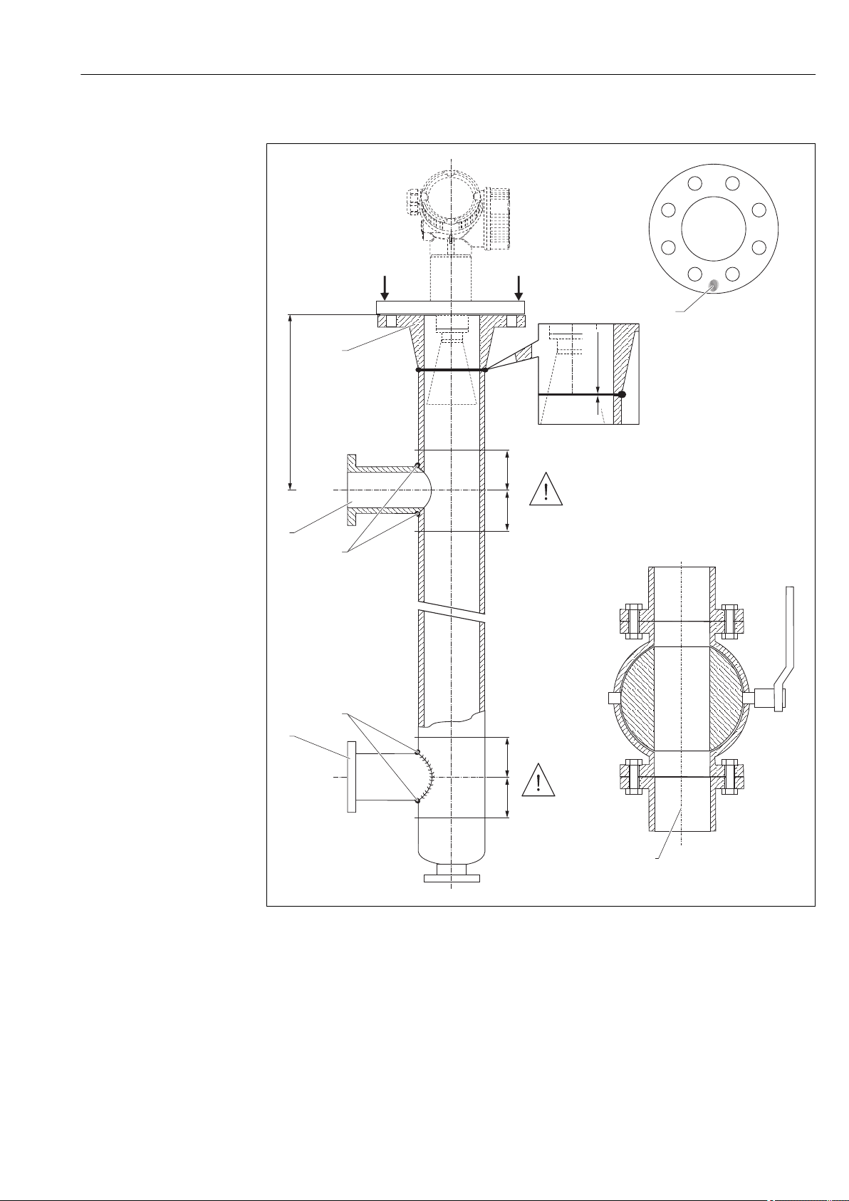
Micropilot FMR51, FMR52 FOUNDATION Fieldbus Installation
100%
0%
A
A A
A-A
mm (in)
200
(7.87)
200
(7.87)
200
(7.87)
200
(7.87)
B
5
4
4
1
2
C
3
3
≤ 1 (0.04)
6.6.2 Example for the construction of a bypass
A Micropilot FMR50/FMR51/FMR52/FMR54: Horn 80mm(3")
B Full bore ball valve
C Minimum distance to upper connection pipe: 400 mm (15,7 in)
1 Marking for axial alignment
2 e.g. welding neck flange DIN2633
3 Diameter of the connection pipes as small as possible
4 Do not weld through the pipe wall; the inside of the bypass must remain smooth.
5 Diameter of opening of ball valve must always be equivalent to pipe diameter. Avoid edges and constrictions.
A0019010
Endress+Hauser 33
Page 34
Installation Micropilot FMR51, FMR52 FOUNDATION Fieldbus
1
2
max.350°
8mm
8mm
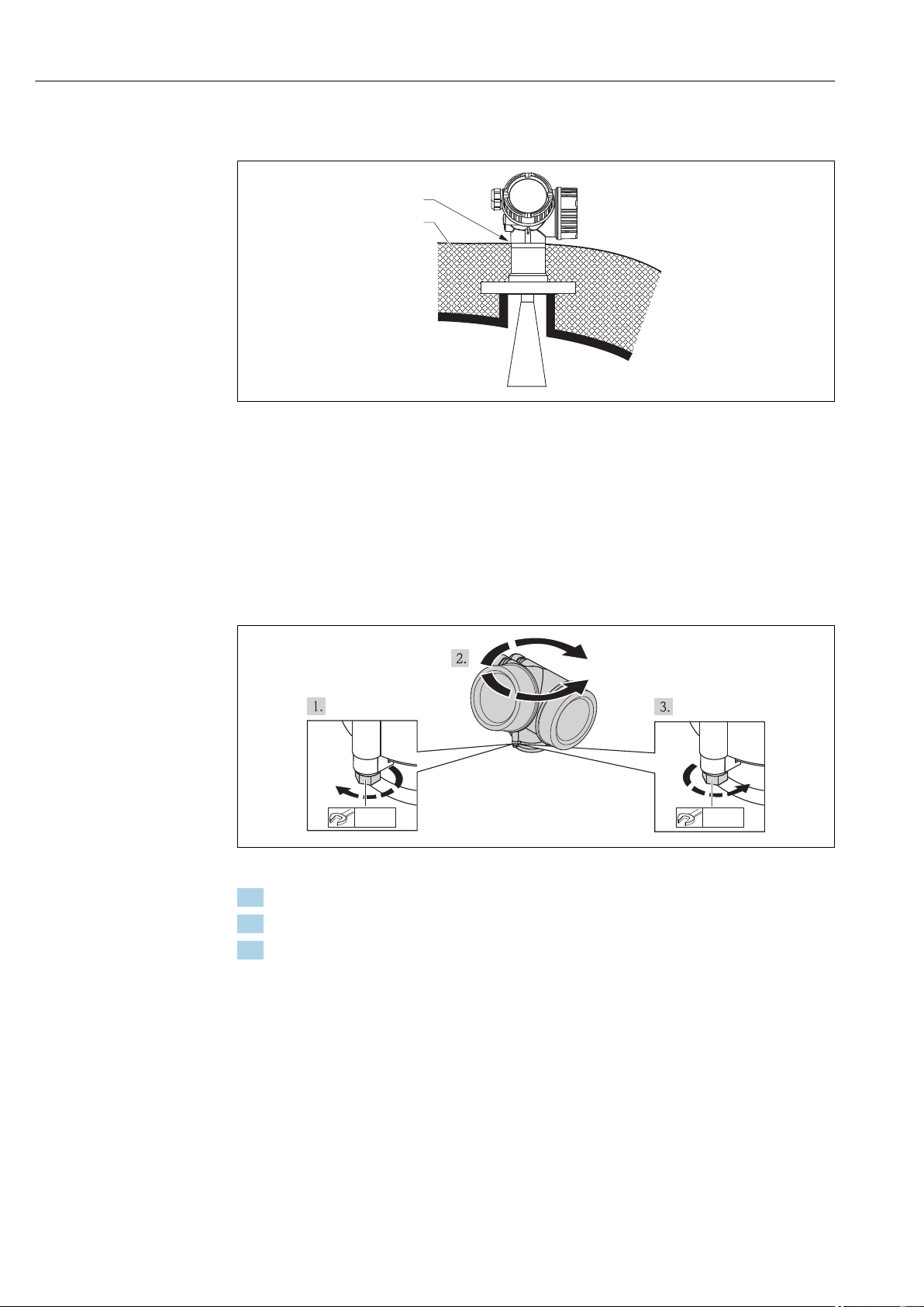
6.7 Vessels with heat insulation
A0019142
If process temperatures are high, the device must be included in normal tank insulation to
prevent the electronics heating up as a result of heat radiation or convection. The
insulation may not exceed beyond the neck of the housing.
6.8 Turning the transmitter housing
To provide easier access to the connection compartment or display module, the transmitter
housing can be turned:
A0013713
1. Unscrew the securing screw using an open-ended wrench.
2. Rotate the housing in the desired direction.
3. Tighten the securing screw (1,5 Nm for plastics housing; 2,5 Nm for aluminium or
stainless steel housing).
34 Endress+Hauser
Page 35
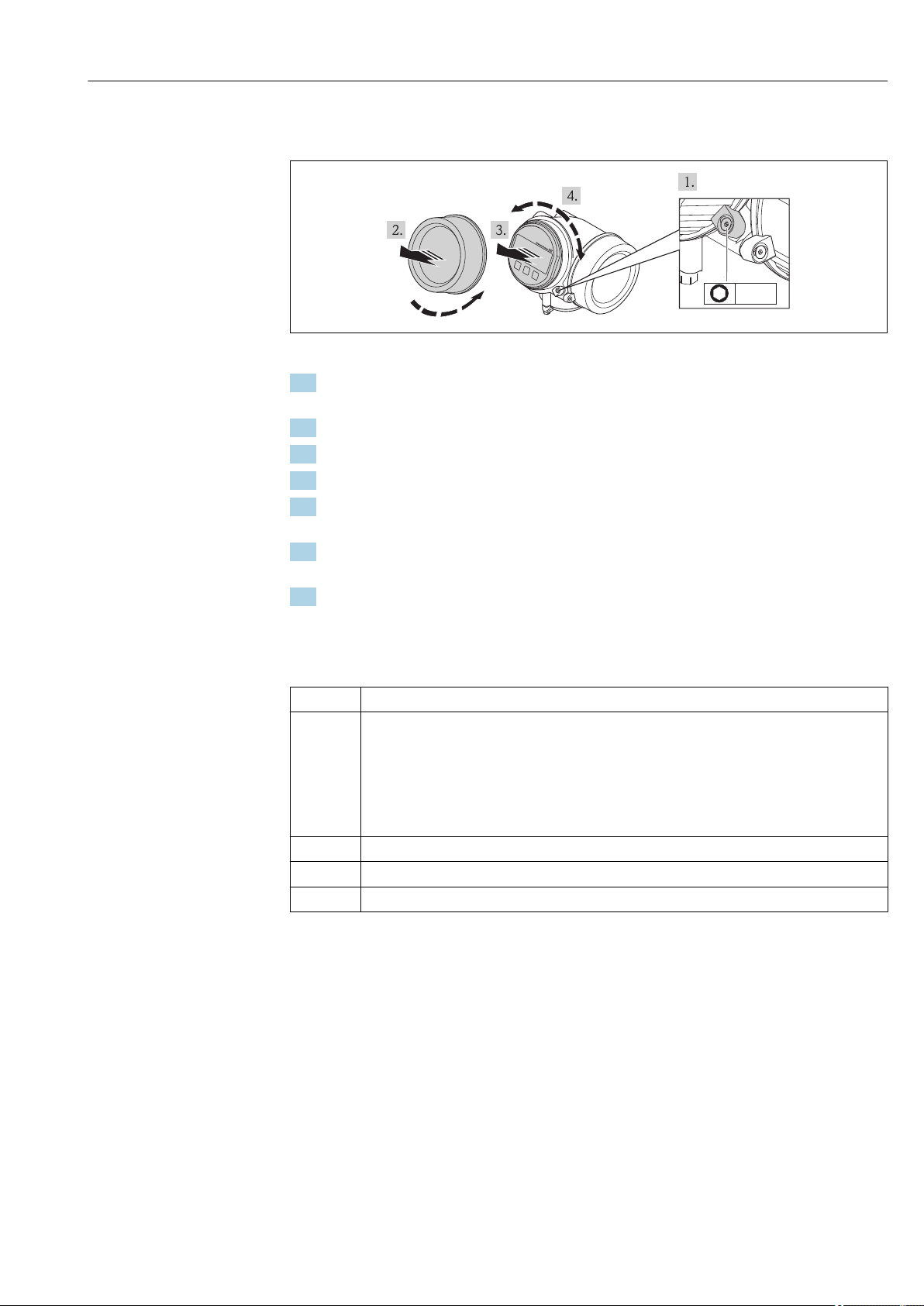
Micropilot FMR51, FMR52 FOUNDATION Fieldbus Installation
+
E
–
1
3mm
6.9 Turning the display module
A0013905
1. If present: Loosen the screw of the securing clamp of the electronics compartment
cover using an Allen key and turn the clamp 90° conterclockwise.
2. Unscrew cover of the electronics compartment from the transmitter housing.
3. Pull out the display module with a gentle rotation movement.
4. Rotate the display module into the desired position: Max. 8 × 45 ° in each direction.
5. Feed the spiral cable into the gap between the housing and main electronics module
and plug the display module into the electronics compartment until it engages.
6. Screw the cover of the electronics compartment firmly back onto the transmitter
housing.
7. Tighten the securing clamp again using the Allen key (Torque: 2.5 Nm).
6.10 Post-installation check
Is the device undamaged (visual inspection)?
Does the device conform to the measuring point specifications?
For example:
• Process temperature
• Process pressure (refer to the chapter on "Material load curves" of the "Technical Information"
document)
• Ambient temperature range
• Measuring range
Are the measuring point identification and labeling correct (visual inspection)?
Is the device adequately protected from precipitation and direct sunlight?
Are the securing screw and securing clamp tightened securely?
Endress+Hauser 35
Page 36
Electrical connection Micropilot FMR51, FMR52 FOUNDATION Fieldbus
1
3
+
+
2
4
FIELDBUS
2-channel overvoltage protection
-
-
[17]
4-20mA/
4-20mA/
B
1
1
+
+
2
2
FIELDBUS
Spare part
71023457
PA/FF
[06/07]
FIELDBUS
-
-
1
3
+
+
2
4
PA/FF
10 mm
Spare part
71108xxx
2- wire level
4-20 mA PFS
FIELDBUS
[26/27]
open
-
-
A
4
1
1
2
3
6
5
3+
3+
4-
4-
!
7 Electrical connection
7.1 Connection conditions
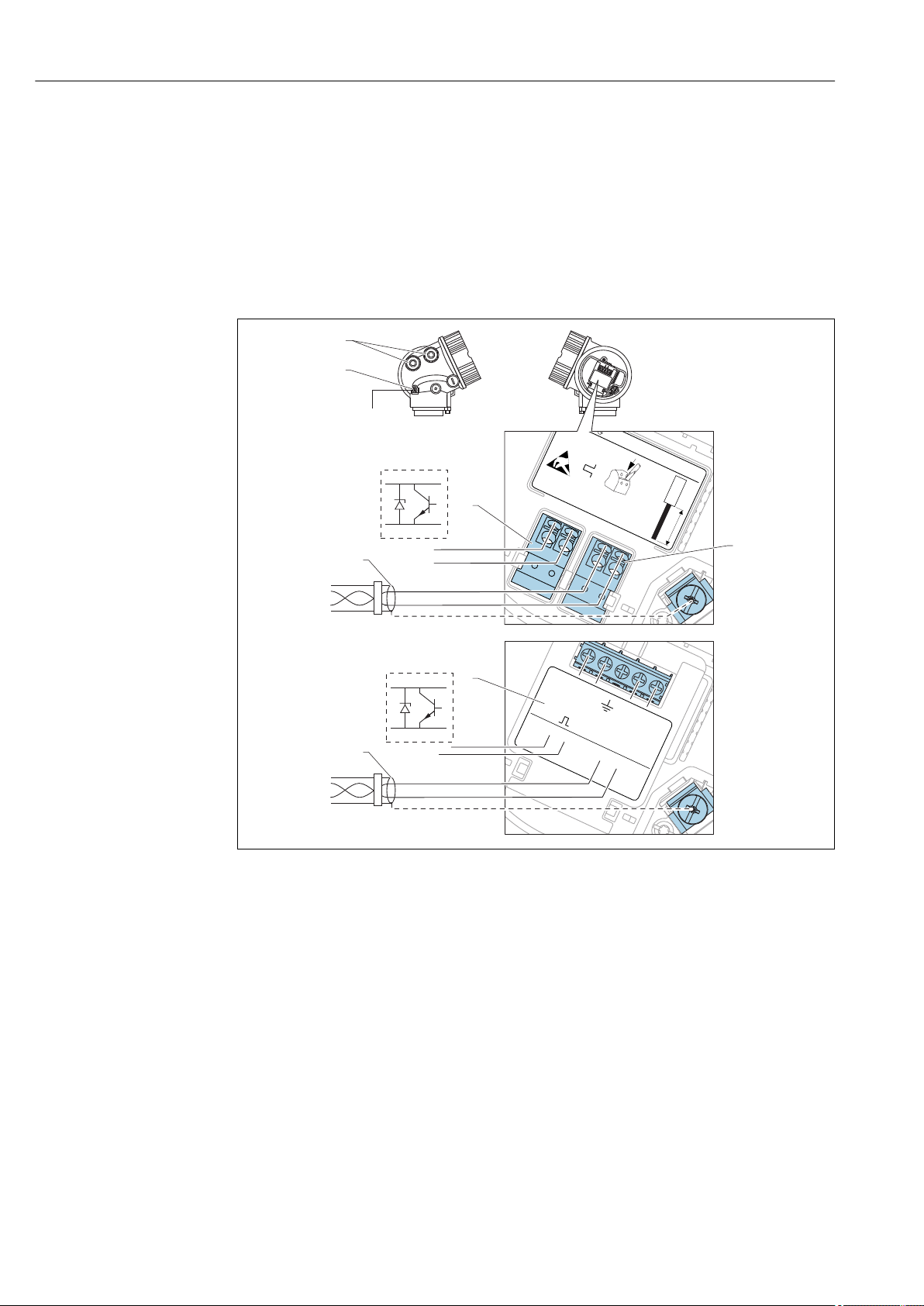
7.1.1 Terminal assignment
PROFIBUS PA / FOUNDATION Fieldbus
10 Terminal assignment PROFIBUS PA / FOUNDATION Fieldbus
A Without integrated overvoltage protection
B With integrated overvoltage protection
1 Cable screen: Observe cable specifications
2 Switch output (open collector): Terminals 3 and 4
3 PROFIBUS PA / FOUNDATION Fieldbus: Terminals 1 and 2
4 Terminal for potential equalization line
5 Cable entries
6 Overvoltage protection module
36 Endress+Hauser
A0011341
Page 37
Micropilot FMR51, FMR52 FOUNDATION Fieldbus Electrical connection
3+
+
-
4-
3+
2
1
+
4-
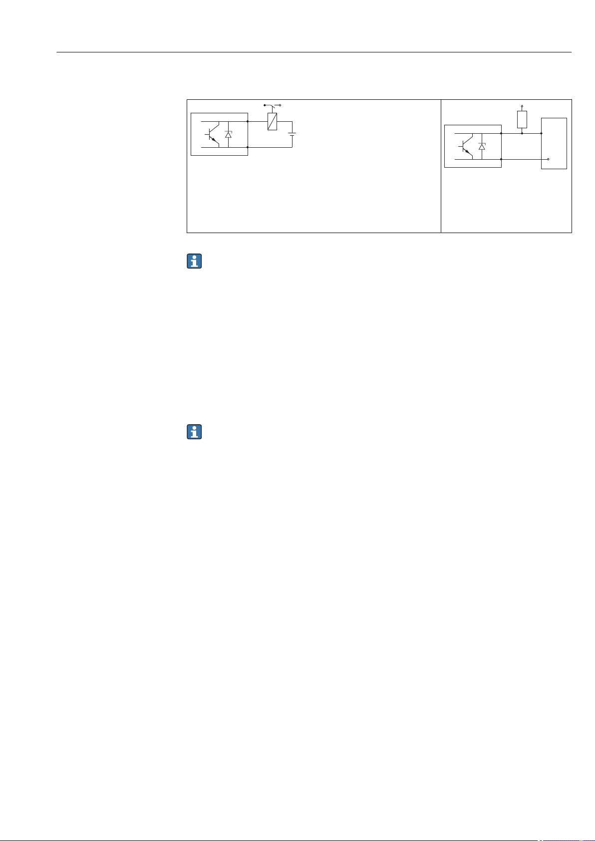
Connection examples for the switch output
A0015909
11 Connection of a relay
Suitable relays (examples):
• Solid-state relay: Phoenix Contact OV-24DC/480AC/5 with mounting
rail connector UMK-1 OM-R/AMS
• Electromechanical relay: Phoenix Contact PLC-RSC-12DC/21
12 Connection of a digital input
1 Pull-up resistor
2 Digital input
A0015910
For optimum interference immunity we recommend to connect an external resistor
(internal resistance of the relay or Pull-up resistor) of < 1 000 Ω.
7.1.2 Cable specification
• Devices without integrated overvoltage protection
Pluggable spring-force terminals for wire cross-sections 0.5 to 2.5 mm2 (20 to 14 AWG)
• Devices with integrated overvoltage protection
Screw terminals for wire cross-sections 0.2 to 2.5 mm2 (24 to 14 AWG)
• For ambient temperature TU≥60 °C (140 °F): use cable for temperature TU +20 K.
FOUNDATION Fieldbus
Endress+Hauser recommends using twisted, shielded two-wire cables.
For further information on the cable specifications, see Operating Instructions
BA00013S "FOUNDATION Fieldbus Overview", FOUNDATION Fieldbus Guideline and
IEC 61158-2 (MBP).
Endress+Hauser 37
Page 38
Electrical connection Micropilot FMR51, FMR52 FOUNDATION Fieldbus
2
1
3
4
4
2
3
1
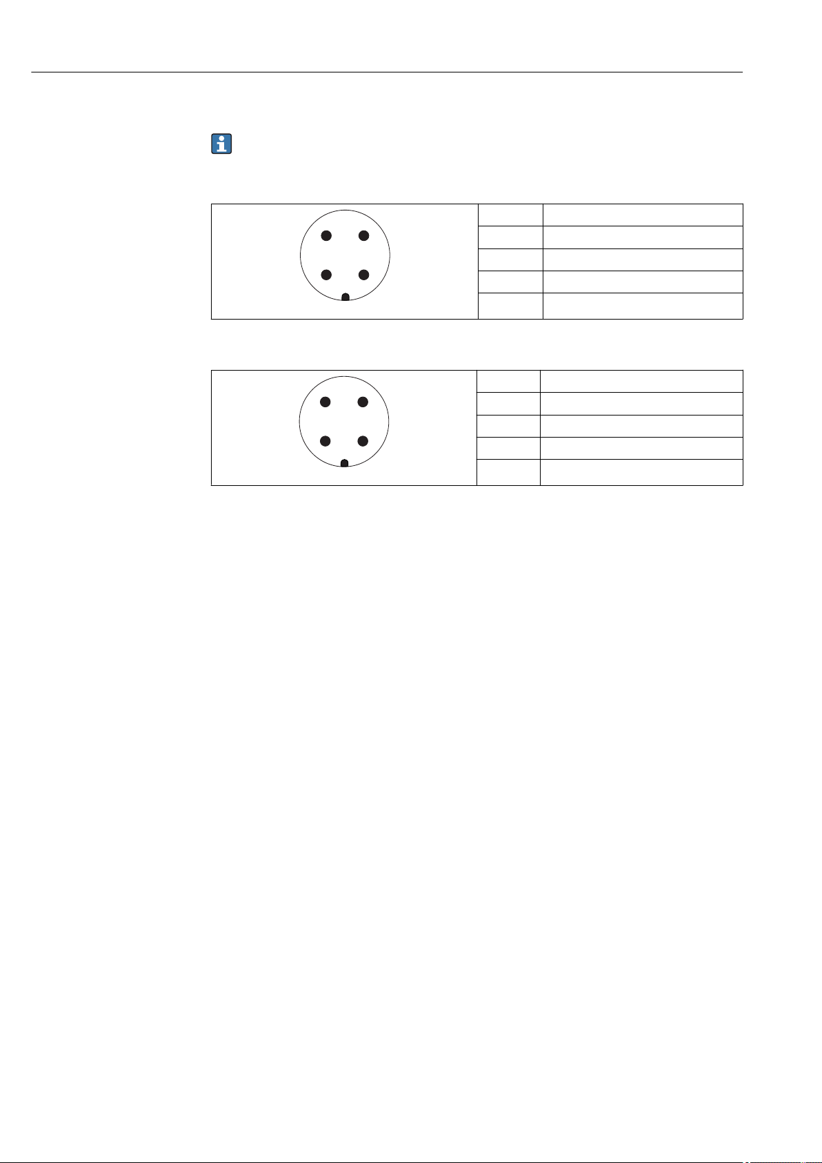
7.1.3 Device plug connectors
For the versions with fieldbus plug connector (M12 or 7/8"), the signal line can be
connected without opening the housing.
Pin assignment of the M12 plug connector
Pin Meaning
1 Signal +
2 not connected
3 Signal -
4 Ground
A0011175
Pin assignment of the 7/8" plug connector
Pin Meaning
1 Signal -
2 Signal +
3 Not connected
4 Screen
A0011176
38 Endress+Hauser
Page 39
Micropilot FMR51, FMR52 FOUNDATION Fieldbus Electrical connection
7.1.4 Supply voltage
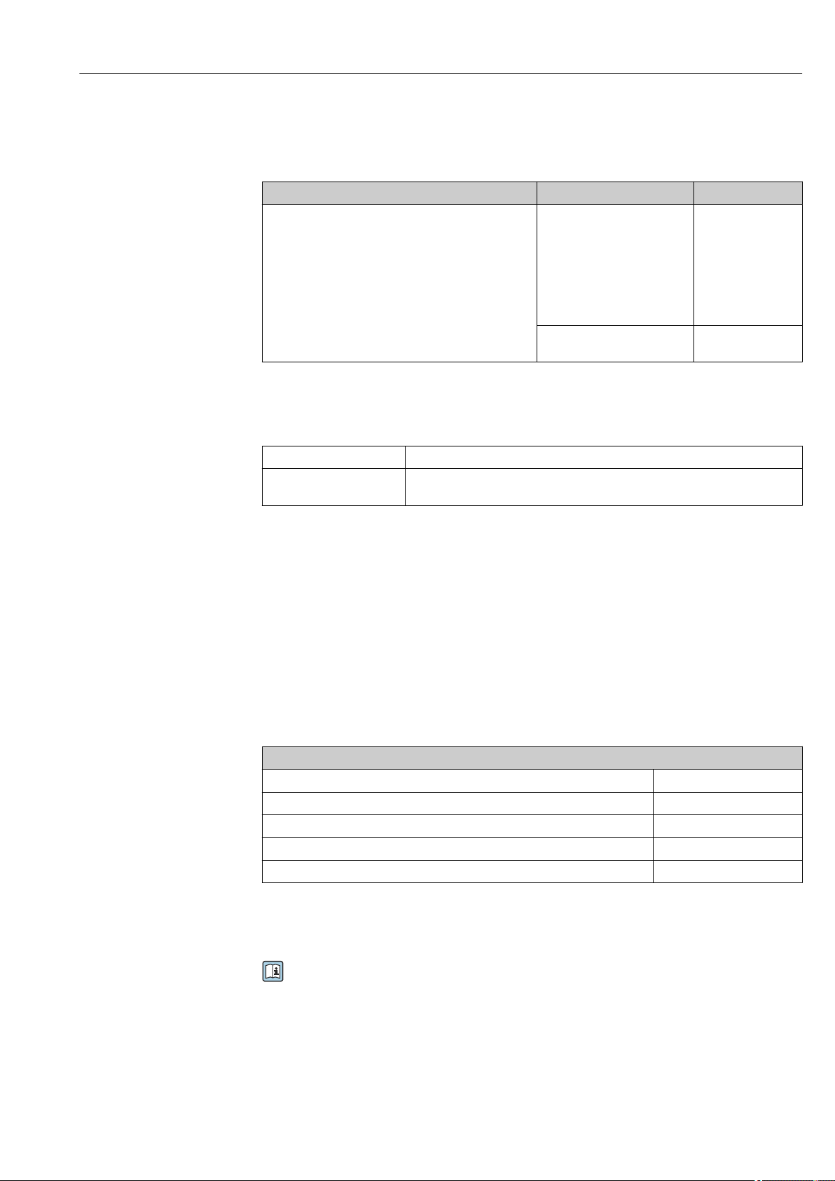
PROFIBUS PA, FOUNDATION Fieldbus
"Power supply; Output"
E: 2-wire; FOUNDATION Fieldbus, switch output
G: 2-wire; PROFIBUS PA, switch output
1) Feature 020 of the product structure
2) Feature 010 of the product structure
3) Input voltages up to 35 V will not spoil the device.
Polarity sensitive No
FISCO/FNICO compliant
according to IEC 60079-27
1)
Yes
"Approval"
• Non-Ex
• Ex nA
• Ex nA(ia)
• Ex ic
• Ex ic(ia)
• Ex d(ia) / XP
• Ex ta / DIP
• CSA GP
• Ex ia / IS
• Ex ia + Ex d(ia) / IS + XP
2)
Terminal voltage
9 to 32 V
9 to 30 V
3)
3)
7.1.5 Overvoltage protection
If the measuring device is used for level measurement in flammable liquids which requires
the use of overvoltage protection according to DIN EN 60079-14, standard for
test procedures 60060-1 (10 kA, pulse 8/20 μs), overvoltage protection has to be ensured
by an integrated or external overvoltage protection module.
Integrated overvoltage protection
An integrated overvoltage protection module is available for 2-wire HART as well as
PROFIBUS PA and FOUNDATION Fieldbus devices.
Product structure: Feature 610 "Accessory mounted", option NA "Overvoltage protection".
Technical data
Resistance per channel 2 × 0.5 Ω max.
Threshold DC voltage 400 to 700 V
Threshold impulse voltage < 800 V
Capacitance at 1 MHz < 1.5 pF
Nominal arrest impulse voltage (8/20 μs) 10 kA
External overvoltage protection
HAW562 or HAW569 from Endress+Hauser are suited as external overvoltage protection.
For detailed information please refer to the following documents:
• HAW562: TI01012K
• HAW569: TI01013K
Endress+Hauser 39
Page 40
Electrical connection Micropilot FMR51, FMR52 FOUNDATION Fieldbus
1.
2.
3.
10 (0.4)
10 (0.4)
mm (in)
4.
5.
5.
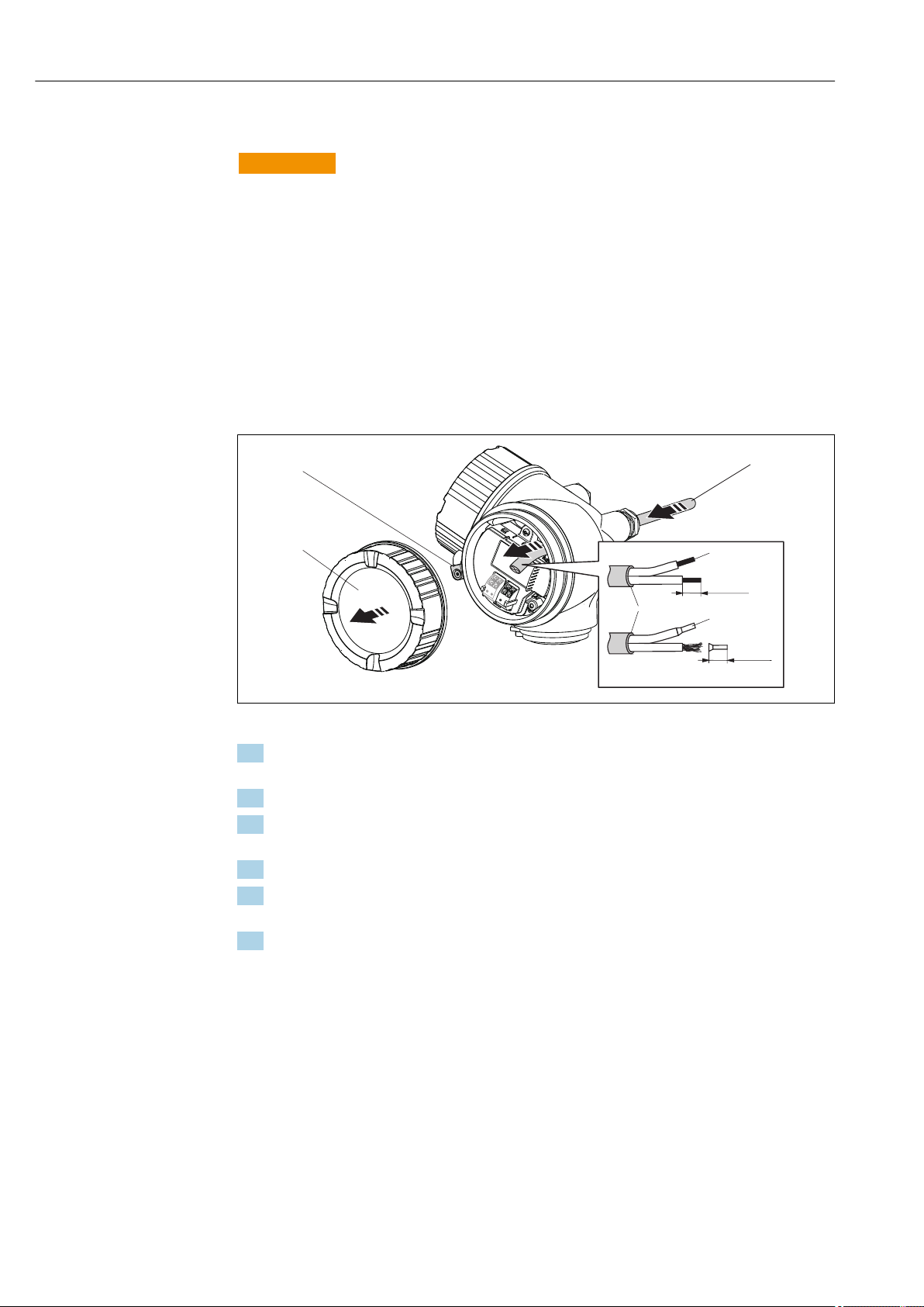
7.2 Connecting the device
WARNING
L
Explosion hazard!
Comply with the relevant national standards.
‣
Observe the specifications in the Safety Instructions (XA).
‣
Only use the specified cable glands.
‣
Check whether the supply voltage matches the specifications on the nameplate.
‣
Before connecting the device: Switch the supply voltage off.
‣
Before switching on the supply voltage: Connect the potential bonding line to the
‣
exterior ground terminal.
Required tools and accessories:
• For instruments with safety pin for the lid: AF 3 Allen key
• Wire stripping pliers
• When using stranded wires: Wire end sleeves.
A0012619
1. Loosen the screw of the securing clamp of the connection compartment cover and
turn the clamp 90° counterclockwise.
2. Unscrew the connection compartment cover.
3. Push the cable through the cable entry. To ensure tight sealing, do not remove the
sealing ring from the cable entry.
4. Strip the cable.
5. Strip the cable ends 10 mm (0.4 in). For stranded cables, also attach wire end
ferrules.
6. Firmly tighten the cable glands.
40 Endress+Hauser
Page 41
Micropilot FMR51, FMR52 FOUNDATION Fieldbus Electrical connection
2
1
4
3
mm(in)
≤ 3(0.12)
7.
A0013837
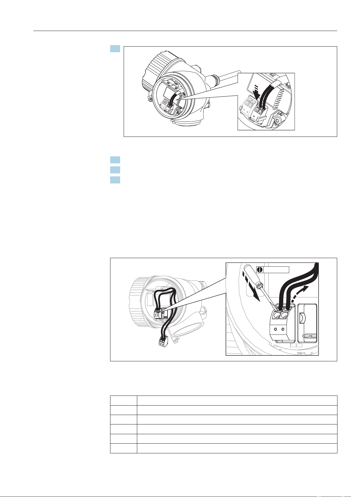
Connect the cable in accordance with the terminal assignment → 36.
8. When using screened cable: Connect the cable screen to the ground terminal.
9. Screw the cover onto the connection compartment.
10. For instruments with safety pin for the lid: Adjust the safety pin so that its edge is
over the edge of the display lid. Tighten the safety pin.
7.2.1 Pluggable spring-force terminals
Instruments without integrated overvoltage protection have pluggable spring-force
terminals. Rigid conductors or flexible conductors with cable sleeve can directly be inserted
and are contacted automatically.
To remove cables from the terminal: Press on the groove between the terminals using a
flat-tip screwdriver ≤ 3 mm (0.12 inch) while pulling the cables out of the terminals.
A0013661
7.3 Post-connection check
Are cables or the device undamaged (visual inspection)?
m
Do the cables comply with the requirements?
m
Do the cables have adequate strain relief?
m
Are all cable glands installed, firmly tightened and correctly sealed?
m
Does the supply voltage match the specifications on the transmitter nameplate?
m
Is the terminal assignment correct → 36?
m
Endress+Hauser 41
Page 42

Electrical connection Micropilot FMR51, FMR52 FOUNDATION Fieldbus
If required: Is the protective earth connected correctly ?
m
If supply voltage is present: Is the device ready for operation and do values appear on the display
m
module?
Are all housing covers installed and firmly tightened?
m
Is the securing clamp tightened correctly?
m
42 Endress+Hauser
Page 43
Micropilot FMR51, FMR52 FOUNDATION Fieldbus Operation options
8 Operation options
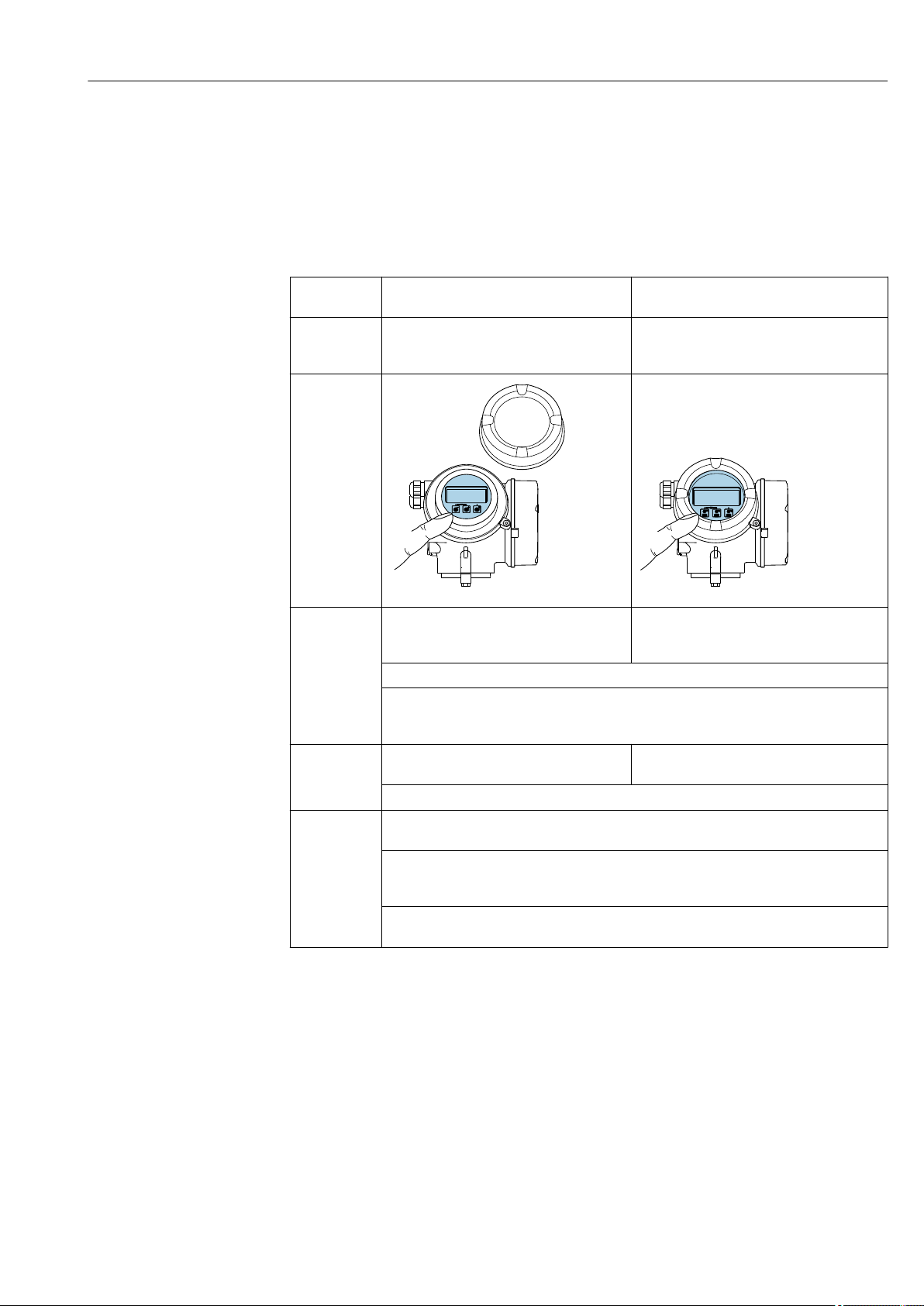
8.1 Overview
8.1.1 Local operation
Operation
with
Order code for
"Display;
Operation"
Display
elements
Operating
elements
Additional
functionality
Pushbuttons Touch Control
Option C "SD02" Option E "SD
A0032219 A0032221
4-line display 4-line display
white background lighting; switches to red in
event of device error
Format for displaying measured variables and status variables can be individually configured
Permitted ambient temperature for the display: –20 to +70 °C (–4 to +158 °F)
The readability of the display may be impaired at temperatures outside the temperature
range.
local operation with 3 push buttons (, ,)external operation via touch control; 3 optical
keys: , ,
Operating elements also accessible in various hazardous areas
Data backup function
The device configuration can be saved in the display module.
Data comparison function
The device configuration saved in the display module can be compared to the current device
configuration.
Data transfer function
The transmitter configuration can be transmitted to another device using the display module.
Endress+Hauser 43
Page 44
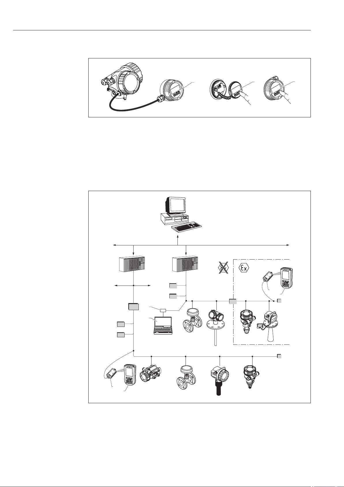
Operation options Micropilot FMR51, FMR52 FOUNDATION Fieldbus
3
2
1
FF-H1
FF-H1
BT
BT
PS
3
4
PS
BT
SB
BT
FF-HSE
IN
LD
ENDRESS + HAUSER
E
+–
%
1
1
2
2
8.1.2 Operation with remote display and operating module FHX50
A0013137
13 FHX50 operating options
1 Housing of the remote display and operating module FHX50
2 Display and operating module SD02, push buttons; cover must be removed
3 Display and operating module SD03, optical keys; can be operated through the glass of the cover
8.1.3 Remote operation
Via FOUNDATION Fieldbus
14 FOUNDATION Fieldbus system architecture with associated components
1 FFblue Bluetooth modem
2 Field Xpert SFX350/SFX370
3 FieldCare
4 NI-FF interface card
44 Endress+Hauser
A0017188
Page 45
Micropilot FMR51, FMR52 FOUNDATION Fieldbus Operation options
+
E
–
12
3
IN Industrial network
FF-HSE High Speed Ethernet
FF-H1 FOUNDATION Fieldbus-H1
LD Linking Device FF-HSE/FF-H1
PS Bus Power Supply
SB Safety Barrier
BT Bus Terminator
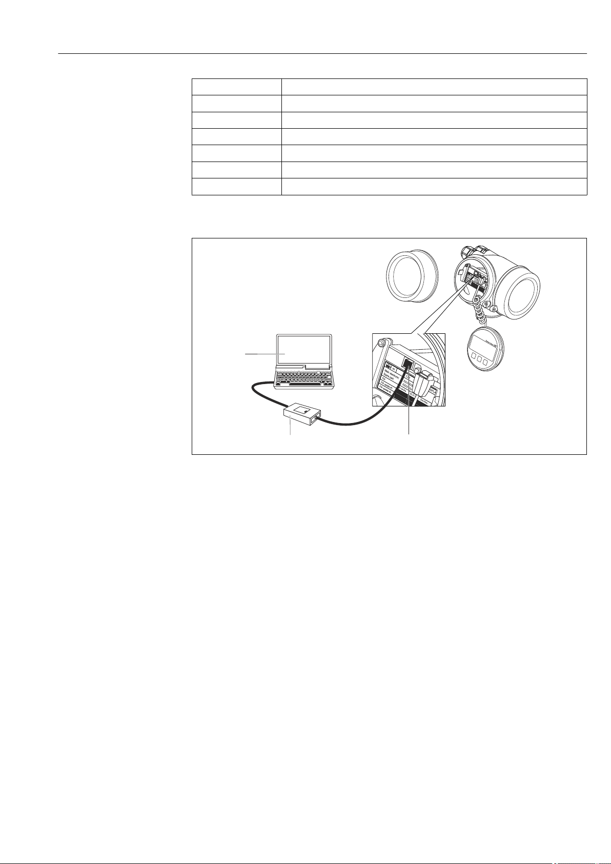
Via service interface (CDI)
1 Service interface (CDI) of the measuring device (= Endress+Hauser Common Data Interface)
2 Commubox FXA291
3 Computer with "FieldCare" operating tool
A0014019
Endress+Hauser 45
Page 46

Operation options Micropilot FMR51, FMR52 FOUNDATION Fieldbus
8.2 Structure and function of the operating menu
8.2.1 Structure of the operating menu
Menu Submenu /
parameter
Language
Setup Parameter 1
...
Parameter N
Advanced setup Contains further submenus and
Diagnostics Diagnostic list Contains up to 5 currently active error
Event logbook
Device information Contains information needed to identify
Measured values Contains all current measured values.
Data logging Contains the history of the individual
Simulation Used to simulate measured values or
Device check Contains all parameters needed to check
Heartbeat
4)
Expert
Contains all parameters of the device
(including those which are already contained
in one of the above submenus). This menu is
organized according to the function blocks of
the device.
The parameter of the Expert menu are
described in:
GP01017F (FOUNDATION Fieldbus)
System Contains all general device parameters
Sensor Contains all parameters needed to
Output Contains all parameters neeed to
Communication Contains all parameters needed to
Diagnostics Contains all parameters needed to
1)
3)
Meaning
Defines the operating language of the
on-site display.
When all these parameters have been
assigned appropriate values, the
measured should be completely
configured in a standard application.
parameters:
• to adapt the device to special
measuring conditions.
• to process the measured value
(scaling, linearization).
• to configure the signal output.
messages.
2)
Contains the last 20 messages (which
are no longer active).
the device.
measuring values.
output values.
the measurement capability of the
device.
Contains all wizards for the Heartbeat
Verification and Heartbeat Monitoring
application packages.
which do not affect the measurement or
the communication interface.
configure the measurement.
configure the switch output (PFS).
configure the digital communication
interface.
detect and analyze operational errors.
1) In case of operation via operating tools (e.g. FieldCare), the "Language" parameter is located at "Setup →
Advanced setup → Display"
2) only available with local operation
3) only available for operation via DeviceCare or FieldCare
4) On entering the "Expert" menu, an access code is always requested. If a customer specific access code has
not been defined, "0000" has to be entered.
46 Endress+Hauser
Page 47

Micropilot FMR51, FMR52 FOUNDATION Fieldbus Operation options
8.2.2 User roles and related access authorization
The two user roles Operator and Maintenance have different write access to the
parameters if a device-specific access code has been defined. This protects the device
configuration via the local display from unauthorized access → 48.
Access authorization to parameters
User role Read access Write access
Without access
code
(from the factory)
Operator --
Maintenance
If an incorrect access code is entered, the user obtains the access rights of the Operator
role.
The user role with which the user is currently logged on is indicated by the Access
status display parameter (for display operation) or Access status tooling parameter
(for tool operation).
With access code Without access
code
(from the factory)
With access code
Endress+Hauser 47
Page 48

Operation options Micropilot FMR51, FMR52 FOUNDATION Fieldbus
8.2.3 Write protection via access code
Using the device-specific access code, the parameters for the measuring device
configuration are write-protected and their values can no longer be changed via local
operation.
Define access code via local display
1. Navigate to: Setup → Advanced setup → Administration → Define access code
→ Define access code
2. Define a max. 4-digit numeric code as an access code.
3. Repeat the same code in Confirm access code parameter.
The -symbol appears in front of all write-protected parameters.
Define access code via operating tool (e.g. FieldCare)
1. Navigate to: Setup → Advanced setup → Administration → Define access code
2. Define a max. 4-digit numeric code as an access code.
Write protection is active.
Parameters that can always be changed
The write protection does not include certain parameters that do not affect the
measurement. Despite the defined access code, they can always be modified, even if the
other parameters are locked.
If no key is pressed for 10 minutes in the navigation and editing mode, the device
automatically locks the write-protected parameters. If the user goes from the navigation
and editing mode back to the measured value display mode, the device automatically locks
the write-protected parameters after 60 s.
• If write access is activated via access code, it can be also be deactivated only via the
access code → 49.
• In the "Description of Device Parameters" documents, each write-protected
parameter is identified with the -symbol.
48 Endress+Hauser
Page 49

Micropilot FMR51, FMR52 FOUNDATION Fieldbus Operation options
8.2.4 Disabling write protection via access code
If the
write-protected by a device-specific access code and its value cannot be changed at the
moment using the local display → 48.
The locking of the write access via local operation can be disabled by entering the devicespecific access code.
-symbol appears on the local display in front of a parameter, the parameter is
1. After you press , the input prompt for the access code appears.
2. Enter the access code.
The -symbol in front of the parameters disappears; all previously write-
protected parameters are now re-enabled.
8.2.5 Deactivation of the write protection via access code
Via local display
1. Navigate to Setup → Advanced setup → Administration → Define access code
→ Define access code
2. Enter 0000.
3. Repeat 0000 in Confirm access code parameter.
The write protection is deactivated. Parameters can be changed without entering
an access code.
Via operating tool (e.g. FieldCare)
1. Navigate to Setup → Advanced setup → Administration → Define access code
2. Enter 0000.
The write protection is deactivated. Parameters can be changed without entering
an access code.
Endress+Hauser 49
Page 50
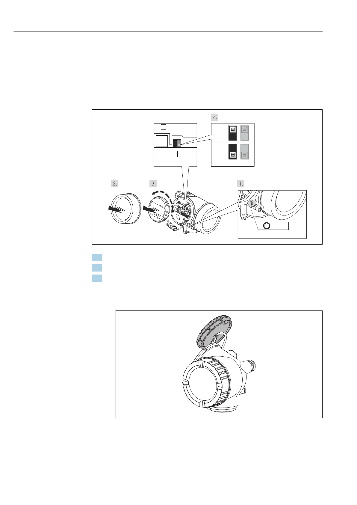
Operation options Micropilot FMR51, FMR52 FOUNDATION Fieldbus
+
E
–
2.5 Nm (1.84 lbf ft)
3 mm
XXXXXXXXXXXXX
WPCDI SIM
ON
WP SIM
OFF
8.2.6 Write protection via write protection switch
Unlike parameter write protection via a user-specific access code, this allows write access
to the entire operating menu - except for the "Contrast display" parameter - to be locked.
The parameter values are now read only and cannot be edited any more (exception
"Contrast display" parameter):
• Via local display
• Via FOUNDATION Fieldbus
1. Loosen the securing clamp.
2. Unscrew the housing cover.
3. Pull out the display module with a gentle rotation movement. To make it easier to
access the lock switch, attach the display module to the edge of the electronics
compartment.
Display module is attached to the edge of the electronics compartment.
A0021474
A0013909
50 Endress+Hauser
Page 51

Micropilot FMR51, FMR52 FOUNDATION Fieldbus Operation options
X X XX X X XX X
20.50
XX
XX
4. Installing the lock switch (WP) on the main electronics module in the ON position
enables the hardware write protection. Installing the lock switch (WP) on the main
electronics module in the OFF position (factory setting) disables the hardware write
protection.
If the hardware write protection is enabled: The Hardware locked option is
displayed in the Locking status parameter. In addition to this, the -symbol
appears in the header of the measured value display and in the navigation view
in front of the parameters.
A0015870
If the hardware write protection is disabled: No option is displayed in the Locking
status parameter. The -symbol disappears in the header of the measured value
display and in the navigation view in front of the parameters.
5. Feed the spiral cable into the gap between the housing and main electronics module
and plug the display module into the electronics compartment in the desired
direction until it engages.
6. Screw the electronics compartment cover closed and tighten the securing clamp.
Endress+Hauser 51
Page 52

Operation options Micropilot FMR51, FMR52 FOUNDATION Fieldbus
8.2.7 Enabling and disabling the keypad lock
The keypad lock allows to disable access to the entire operating menu via local operation.
Thus navigating through the operating menu or modifying the values of individual
parameters is no longer possible. Only the measured values on the measured value display
can be read off.
The keylock is enabled and disabled via a context menu.
Enabling the keylock
For the SD03 display:
The keylock is automatically activated:
• If the device has not been operated via the display for > 1 minute.
• After a restart of the device.
To activate the keylock manually:
1. The device is in the measured value display.
Press for at least 2 seconds.
A context menu appears.
2. Select Keylock on from the context menu.
The keylock is enabled.
When attempting to access the operating menu while the keylock is enabled, the
Keylock on message appears.
Disabling the keylock
1. The keylock is enabled.
Press for at least 2 seconds.
A context menu appears.
2. Select Keylock off from the context menu.
The keylock is disabled.
52 Endress+Hauser
Page 53
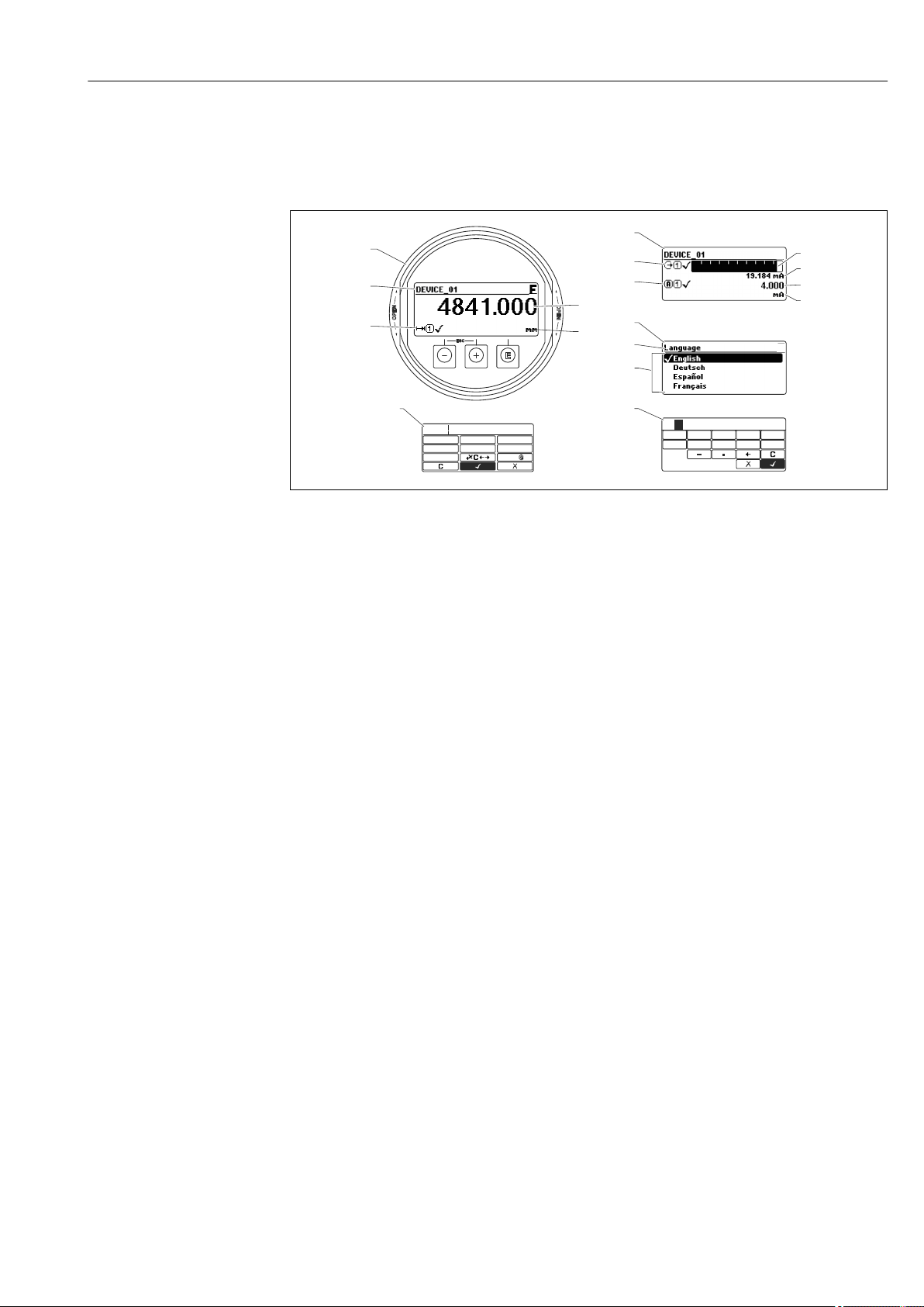
Micropilot FMR51, FMR52 FOUNDATION Fieldbus Operation options
3.1
3.2
2.1
2.2
2.4
2.5
1.1
1.2
1.3
1.4
2.3
2.6
1
2
3
45
ESC
OPEN
OPEN
E
ABC_
DEFG
User
HIJK
LMNO
PQRS
TUVW
XYZ
Aa1
3
4
0
1 2
9
5
6
8
7
20
8.3 Display and operating module
8.3.1 Display appearance
A0012635
15 Appearance of the display and operation module for on-site operation
1 Measured value display (1 value max. size)
1.1 Header containing tag and error symbol (if an error is active)
1.2 Measured value symbols
1.3 Measured value
1.4 Unit
2 Measured value display (1 bargraph + 1 value)
2.1 Bargraph for measured value 1
2.2 Measured value 1 (including unit)
2.3 Measured value symbols for measured value 1
2.4 Measured value 2
2.5 Unit for measured value 2
2.6 Measured value symbols for measured value 2
3 Representation of a parameter (here: a parameter with selection list)
3.1 Header containing parameter name and error symbol (if an error is active)
3.2 Selection list; marks the current parameter value.
4 Input matrix for numbers
5 Input matrix for alphanumeric and special characters
Endress+Hauser 53
Page 54
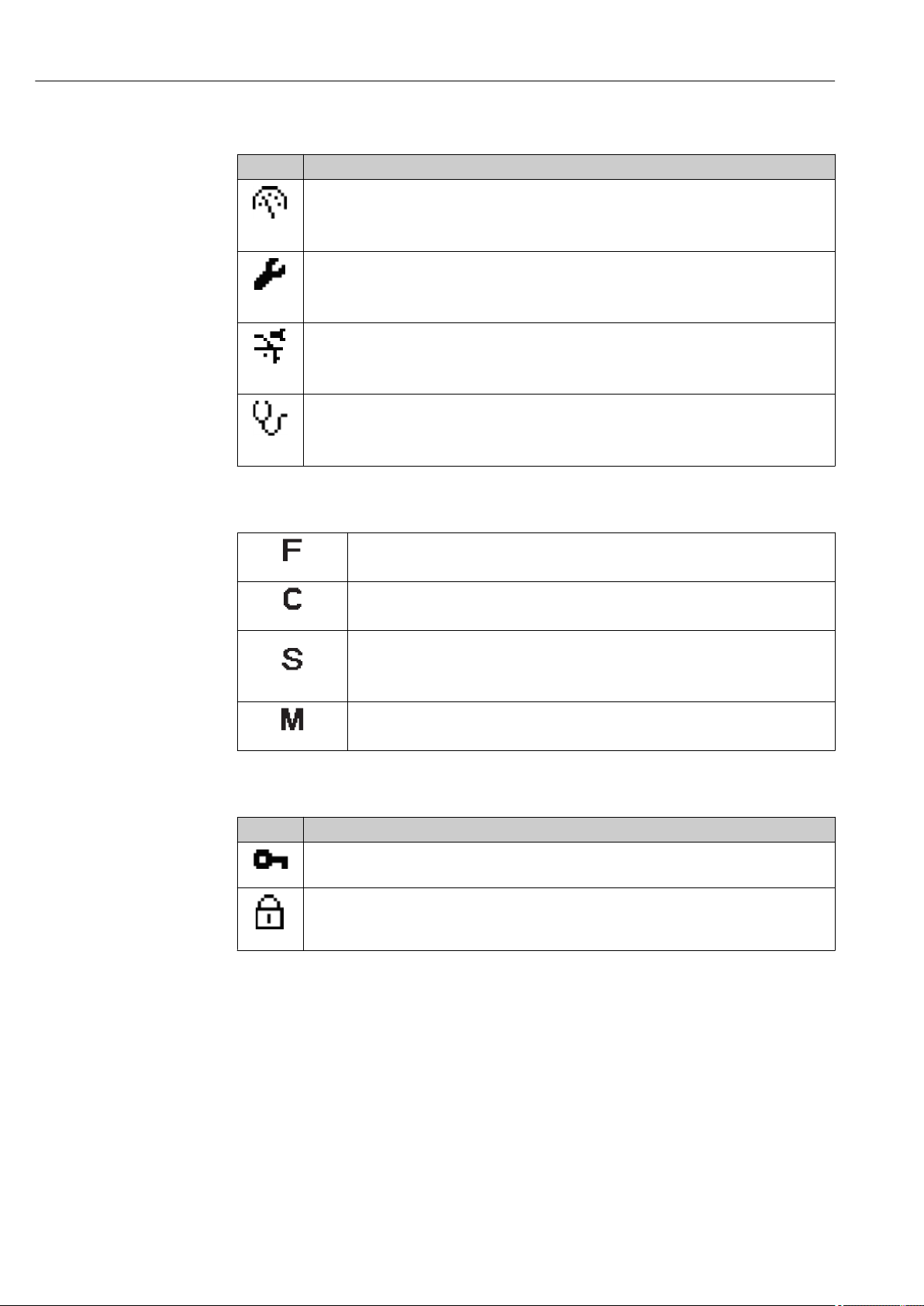
Operation options Micropilot FMR51, FMR52 FOUNDATION Fieldbus
Display symbols for the submenus
Symbol Meaning
Display/operation
Is displayed:
• in the main menu next to the selection "Display/operation"
A0011975
• in the header, if you are in the "Display/operation" menu
Setup
Is displayed:
• in the main menu next to the selection "Setup"
A0011974
• in the header, if you are in the "Setup" menu
Expert
Is displayed:
• in the main menu next to the selection "Expert"
A0011976
• in the header, if you are in the "Expert" menu
Diagnostics
Is displayed:
• in the main menu next to the selection "Diagnostics"
A0011977
• in the header, if you are in the "Diagnostics" menu
Status signals
"Failure"
A device error is present. The measured value is no longer valid.
A0013956
"Function check"
The device is in service mode (e.g. during a simulation).
A0013959
"Out of specification"
The device is operated:
• Outside of its technical specifications (e.g. during startup or a cleaning)
A0013958
• Outside of the configuration carried out by the user (e.g. level outside configured span)
"Maintenance required"
Maintenance is required. The measured value is still valid.
A0013957
Display symbols for the locking state
Symbol Meaning
Display parameter
Marks display-only parameters which can not be edited.
A0011978
Device locked
• In front of a parameter name: The device is locked via software and/or hardware.
• In the header of the measured value screen: The device is locked via hardware.
A0011979
54 Endress+Hauser
Page 55
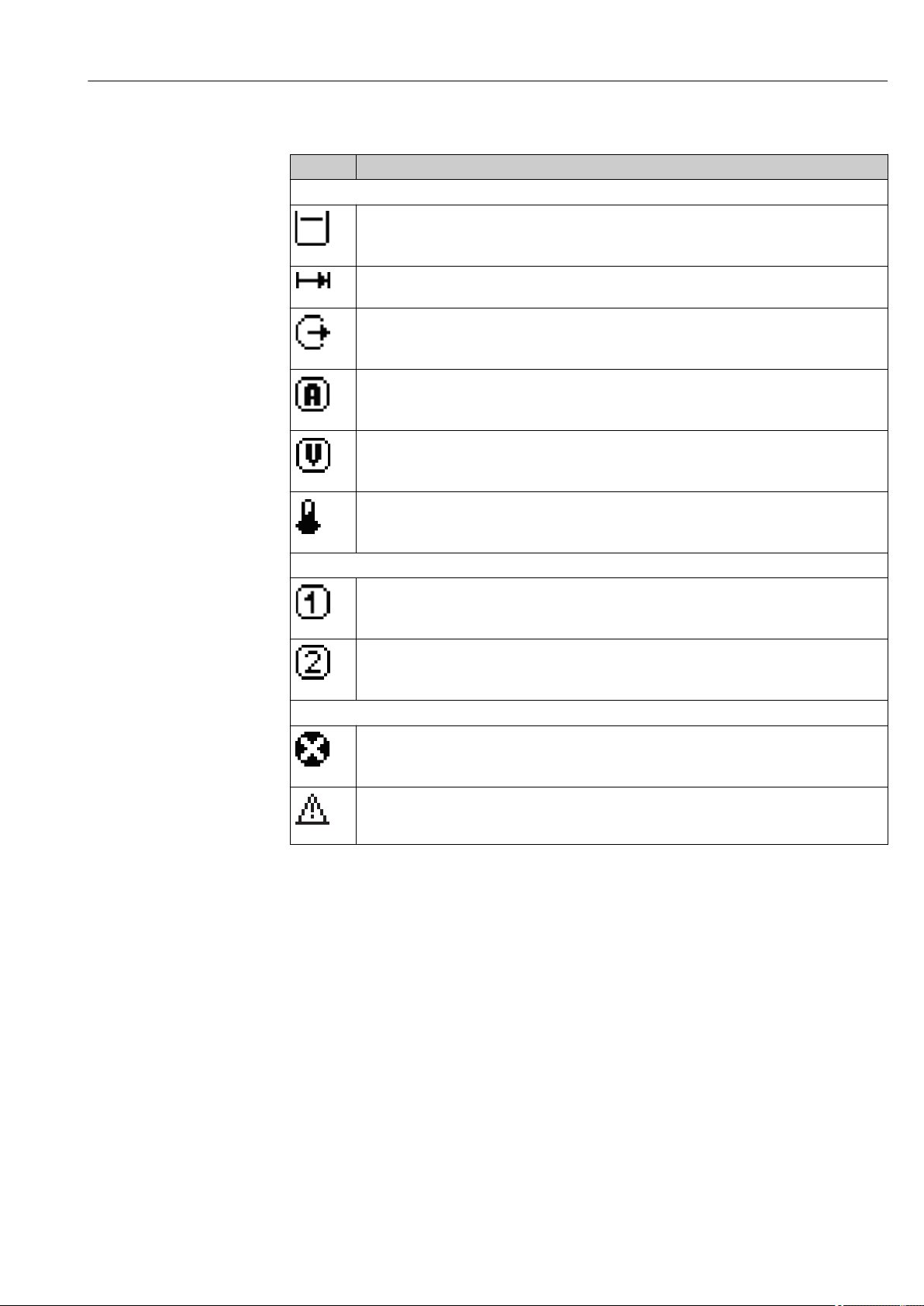
Micropilot FMR51, FMR52 FOUNDATION Fieldbus Operation options
Measured value symbols
Symbol Meaning
Measured values
Level
A0011995
Distance
A0011996
Current output
A0011998
Measured current
A0011999
Terminal voltage
A0012106
Temperature of the electronics or the sensor
A0012104
Measuring channels
Measuring channel 1
A0012000
Measuring channel 2
A0012107
Status of the measured value
Status "Alarm"
The measurment is interrupted. The output assumes the defined alarm value. A diagnostic
message is generated.
A0012102
Status "Warning"
The device continues measuring. A diagnostic message is generated.
A0012103
Endress+Hauser 55
Page 56
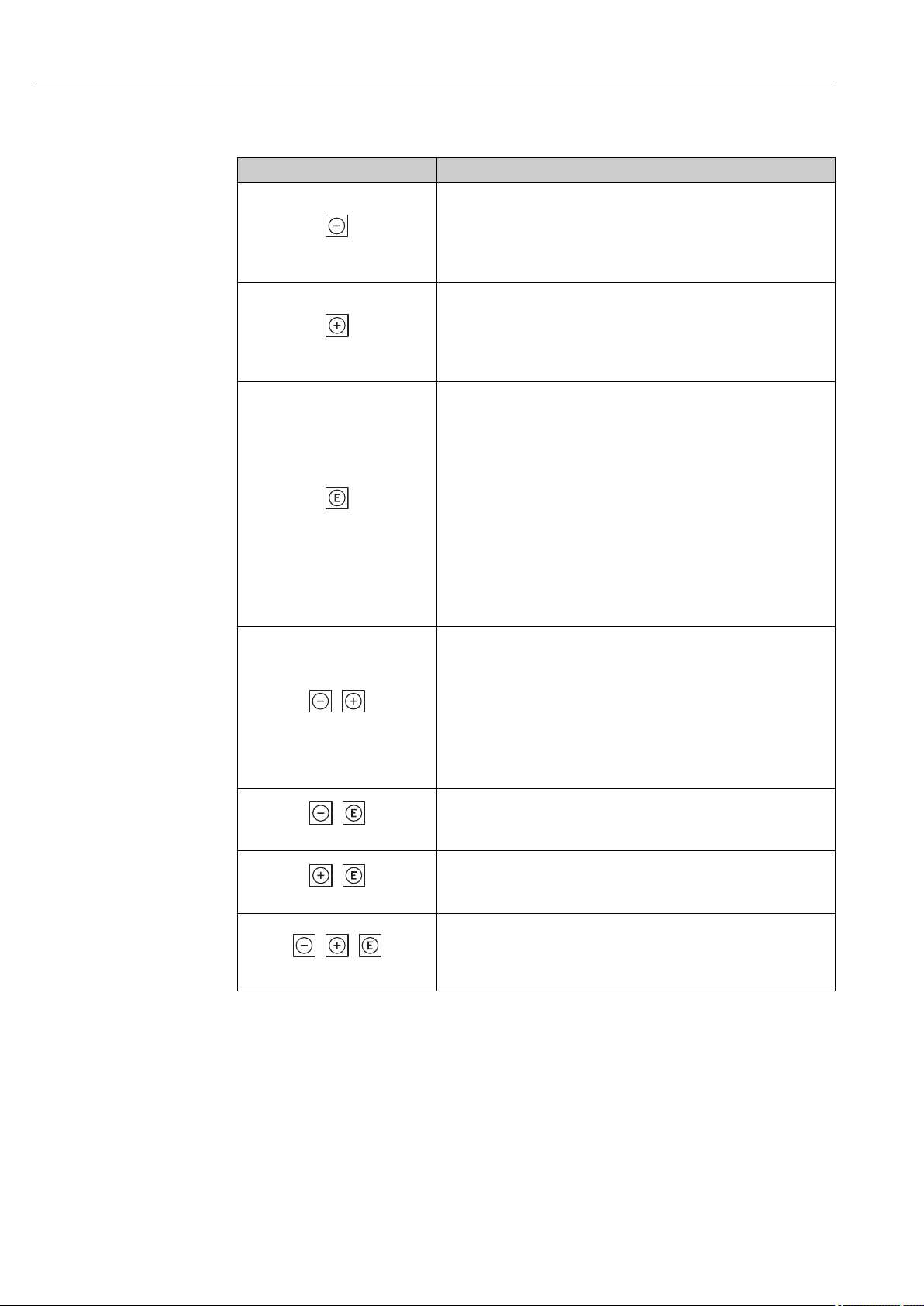
Operation options Micropilot FMR51, FMR52 FOUNDATION Fieldbus
+
+
+
++
8.3.2 Operating elements
Key Meaning
Minus key
For menu, submenu
Moves the selection bar upwards in a picklist.
A0013969
For text and numeric editor
In the input mask, moves the selection bar to the left (backwards).
Plus key
For menu, submenu
Moves the selection bar downwards in a picklist.
A0013970
For text and numeric editor
In the input mask, moves the selection bar to the right (forwards).
Enter key
For measured value display
• Pressing the key briefly opens the operating menu.
• Pressing the key for 2 s opens the context menu.
For menu, submenu
• Pressing the key briefly
Opens the selected menu, submenu or parameter.
• Pressing the key for 2 s for parameter:
A0013952
A0013971
A0013953
A0013954
A0013955
If present, opens the help text for the function of the parameter.
For text and numeric editor
• Pressing the key briefly
– Opens the selected group.
– Carries out the selected action.
• Pressing the key for 2 s confirms the edited parameter value.
Escape key combination (press keys simultaneously)
For menu, submenu
• Pressing the key briefly
– Exits the current menu level and takes you to the next higher level.
– If help text is open, closes the help text of the parameter.
• Pressing the key for 2 s returns you to the measured value display
("home position").
For text and numeric editor
Closes the text or numeric editor without applying changes.
Minus/Enter key combination (press and hold down the keys
simultaneously)
Reduces the contrast (brighter setting).
Plus/Enter key combination (press and hold down the keys
simultaneously)
Increases the contrast (darker setting).
Minus/Plus/Enter key combination (press and hold down the keys
simultaneously)
For measured value display
Enables or disables the keypad lock.
56 Endress+Hauser
Page 57
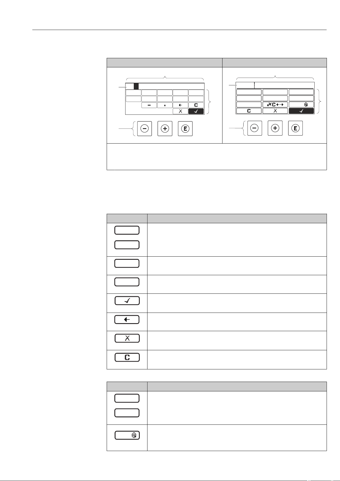
Micropilot FMR51, FMR52 FOUNDATION Fieldbus Operation options
3
2
1
4
3
4
0
1 2
9
5
6
8
7
20
ABC_
DEFG
User
HIJK
LMNO
PQRS
TUVW
XYZ
Aa1
3
2
1
4
…
0
9
.
–
XYZ
ABC
_
…
Aa1
8.3.3 Entering numbers and text
Numeric editor Text editor
A0013999
1
Editing view
2
Display area of the entered values
3
Input mask
4
Operating elements
A0013941
Input mask
The following input symbols are available in the input mask of the numeric and text editor:
Numeric editor symbols
Symbol Meaning
Selection of numbers from 0 to 9.
A0013998
Inserts decimal separator at the input position.
A0016619
Inserts minus sign at the input position.
A0016620
Confirms selection.
A0013985
Moves the input position one position to the left.
A0016621
Exits the input without applying the changes.
A0013986
Clears all entered characters.
A0014040
Text editor symbols
Symbol Meaning
Selection of letters from A to Z
Endress+Hauser 57
A0013997
Toggle
• Between upper-case and lower-case letters
• For entering numbers
A0013981
• For entering special characters
Page 58
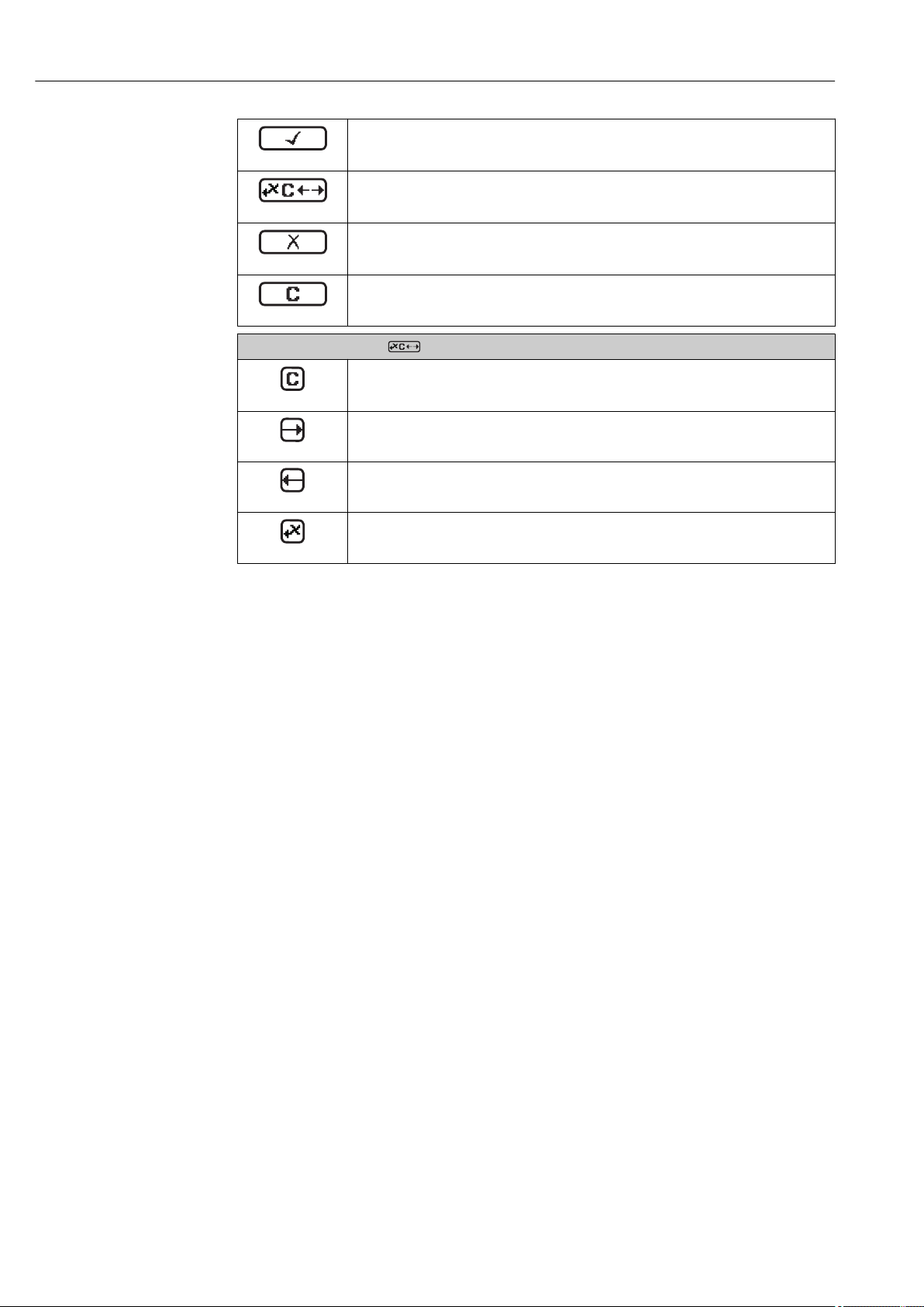
Operation options Micropilot FMR51, FMR52 FOUNDATION Fieldbus
Confirms selection.
A0013985
Switches to the selection of the correction tools.
A0013987
Exits the input without applying the changes.
A0013986
Clears all entered characters.
A0014040
Correction symbols under
Clears all entered characters.
A0013989
Moves the input position one position to the right.
A0013991
Moves the input position one position to the left.
A0013990
Deletes one character immediately to the left of the input position.
A0013988
58 Endress+Hauser
Page 59
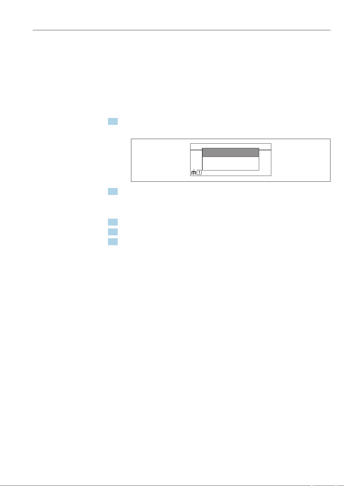
Micropilot FMR51, FMR52 FOUNDATION Fieldbus Operation options
XXXXXXXXXX
kg/h
20.50
Setup
Conf.backupdisp
Simulation
8.3.4 Opening the context menu
Using the context menu, the user can call up the following menus quickly and directly from
the operational display:
• Setup
• Conf. backup disp.
• Simulation
Calling up and closing the context menu
The user is in the operational display.
1. Press for 2 s.
The context menu opens.
A0014003-EN
2. Press + simultaneously.
The context menu is closed and the operational display appears.
Calling up the menu via the context menu
1. Open the context menu.
2. Press to navigate to the desired menu.
3. Press to confirm the selection.
The selected menu opens.
Endress+Hauser 59
Page 60
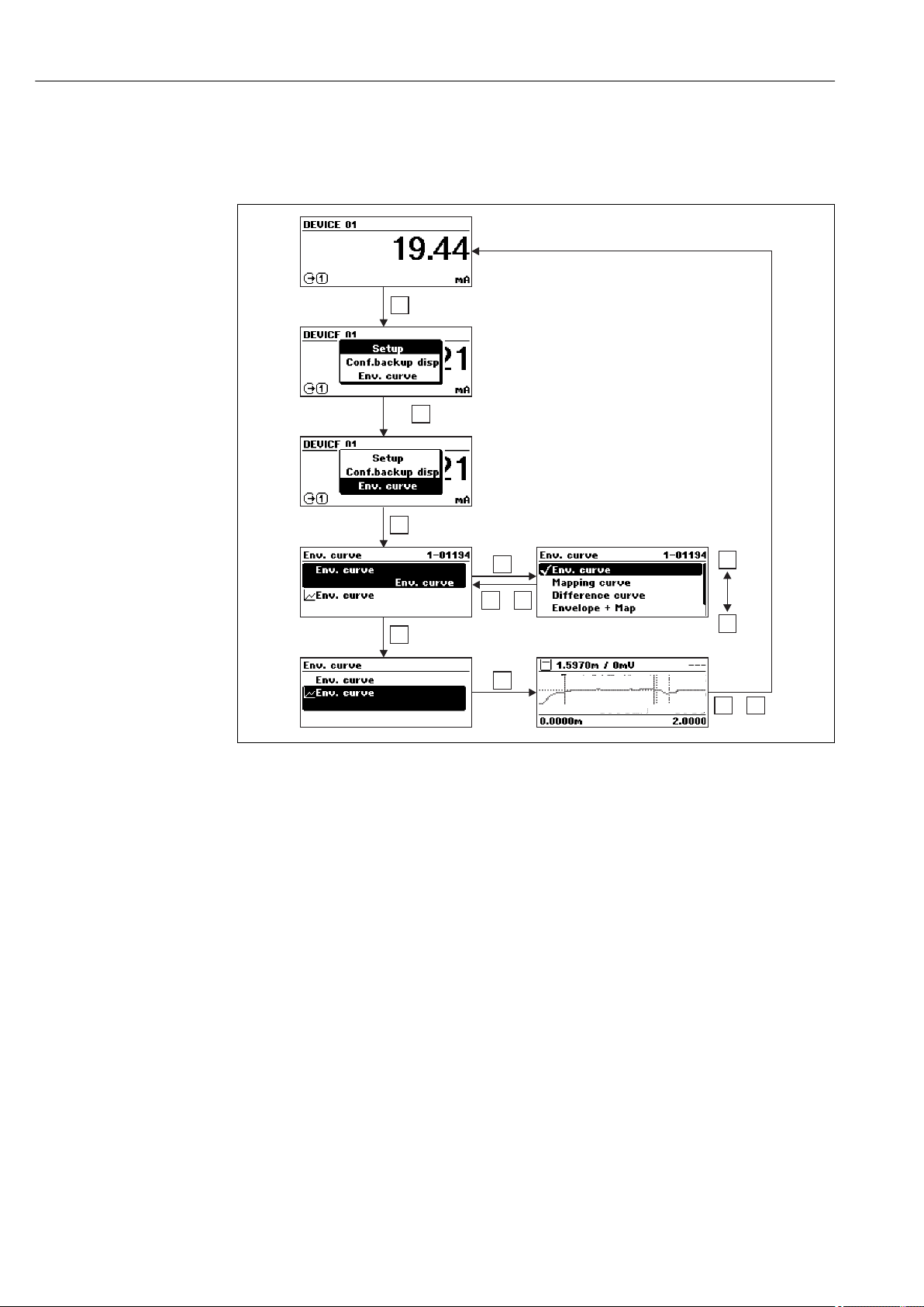
Operation options Micropilot FMR51, FMR52 FOUNDATION Fieldbus
E
+
(2s)
E
2x
E
+
-
+
+
-
+
E
+
-
+
8.3.5 Envelope curve on the display and operating module
In order to assess the measuring signal, the envelope curve and - if a mapping has been
recorded - the mapping curve can be displayed:
A0014277
60 Endress+Hauser
Page 61

Micropilot FMR51, FMR52 FOUNDATION Fieldbus Integration into a FOUNDATION Fieldbus network
9 Integration into a FOUNDATION Fieldbus
network
9.1 Device Description (DD)
You require the following to configure a device and integrate it into an FF network:
• An FF configuration program
• The Cff file (Common File Format: *.cff)
• The device description (DD) in one of the following formats
– Device Description format 4 : *sym, *ffo
– Device Description format 5 : *sy5, *ff5
Information on the device-specific DD
Manufacturer ID 0x452B48
Device Type 0x1028
Device Revision 0x01
DD Revision Information and files at:
CFF Revision
• www.endress.com
• www.fieldbus.org
9.2 Integration into the FOUNDATION Fieldbus network
• For more in-depth information on integrating the device into the FF system, see the
description for the configuration software used.
• When integrating the field devices into the FF system, make sure you are using the
right files. You can read out the required version by means of the Device Revision/
DEV_REV and DD Revision/ DD_REV parameters in the Resource Block.
The device is integrated into the FF network as follows:
1. Start the FF configuration program.
2. Download the Cff and device description files (*.ffo, *.sym (for format 4) *ff5, *sy5
(for format 5) to the system.
3. Configure the interface.
4. Configure the device for the measuring task and for the FF system.
9.3 Device identification and addressing
FOUNDATION Fieldbus identifies the device using its ID code (Device ID) and automatically
assigns it a suitable field address. The identity code cannot be changed. The device appears
in the network display once you have started the FF configuration program and integrated
the device into the network. The blocks available are displayed under the device name.
If the device description has not yet been loaded, the blocks report "Unknown" or "(UNK)".
Endress+Hauser 61
Page 62

Integration into a FOUNDATION Fieldbus network Micropilot FMR51, FMR52 FOUNDATION Fieldbus
–
–
RESOURCE_xxxxxxxxxxx (RB2)
EH_Micropilot_xxxxxxxxxx
SETUP_ (TRDSUP)xxxxxxxxxxx
DISPLAY_ (TRDDISP)xxxxxxxxxxx
DIAGNOSTIC_ (TRDDIAG)xxxxxxxxxxx
EXPERT_CONFIG_ (TRDEXP)xxxxxxxxxxx
EXPERT_INFO_ (TRDEXPIN)xxxxxxxxxxx
SERVICE_INFO_ (TRDSRVIF)xxxxxxxxxxx
DATA_TRANSFER_ (TRDHROM)xxxxxxxxxxx
ANALOG_INPUT_1_ (AI)xxxxxxxxxxx
ANALOG_INPUT_2_ (UNK)xxxxxxxxxxx
DISCRETE_INPUT_ (DI)xxxxxxxxxxx
MULTIPLE_AO_ (MAO)xxxxxxxxxxx
ARITHMETIC_ (AR)xxxxxxxxxxx
INPUT_SELECTOR_ (ISEL)xxxxxxxxxxx
ANALOG_ALARM_ (AAL)xxxxxxxxxxx
PID_ (PID)xxxxxxxxxxx
MULTIPLE_DO_ (MDO)xxxxxxxxxxx
SIGNAL_CHAR_ (SC)xxxxxxxxxxx
INTEGRATOR_ (IT)xxxxxxxxxxx
SERVICE_SENSOR_ (TRDSRVSB)xxxxxxxxxxx
ADV_SETUP_ (TRDASUP)xxxxxxxxxxx
1 2
16 Typical display in a configuration program after the connection has been established
1 Device name
2 Serial number
62 Endress+Hauser
A0020711
Page 63

Micropilot FMR51, FMR52 FOUNDATION Fieldbus Integration into a FOUNDATION Fieldbus network
9.4 Block model
9.4.1 Blocks of the device software
The device has the following blocks:
• Resource Block (device block)
• Transducer Blocks
– Setup Transducer Block (TRDSUP)
– Advanced Setup Transducer Block (TRDASUP)
– Display Transducer Block (TRDDISP)
– Diagnostic Transducer Block (TRDDIAG)
– Advanced Diagnostic Transducer Block (TRDADVDIAG)
– Expert Configuration Transducer Block (TRDEXP)
– Expert Information Transducer Block (TRDEXPIN)
– Service Sensor Transducer Block (TRDSRVSB)
– Service Information Transducer Block (TRDSRVIF)
– Data Transfer Transducer Block (TRDHROM)
• Function Blocks
– 2 AI Blocks (AI)
– 1 Discrete Input Block (DI)
– 1 Multiple Analog Output Block (MAO)
– 1 Mutliple Discrete Output Block (MDO)
– 1 PID Block (PID)
– 1 Arithmetic Block (AR)
– 1 Signal Characterizer Block (SC)
– 1 Input Selector Block (ISEL)
– 1 Integrator Block (IT)
– 1 Analog Alarm Block (AAL)
In addition to the pre-instantiated blocks already mentioned, the following blocks can also
be instantiated:
• 3 AI Blocks (AI)
• 2 Discrete Input Blocks (DI)
• 1 PID Block (PID)
• 1 Arithemetic Block (AR)
• 1 Signal Characterizer Block (SC)
• 1 Input Selector Block (ISEL)
• 1 Integrator Block (IT)
• 1 Analog Alarm Block (AAL)
Up to 20 blocks can be instantiated in the device altogether, including the blocks already
instantiated. For instantiating blocks, see the appropriate Operating Instructions of the
configuration program used.
Endress+Hauser Guideline BA00062S.
The guideline provides an overview of the standard function blocks that are described
in FOUNDATION Fieldbus Specifications FF 890 - 894. It is designed to help operators
use the blocks implemented in the Endress+Hauser field devices.
Endress+Hauser 63
Page 64
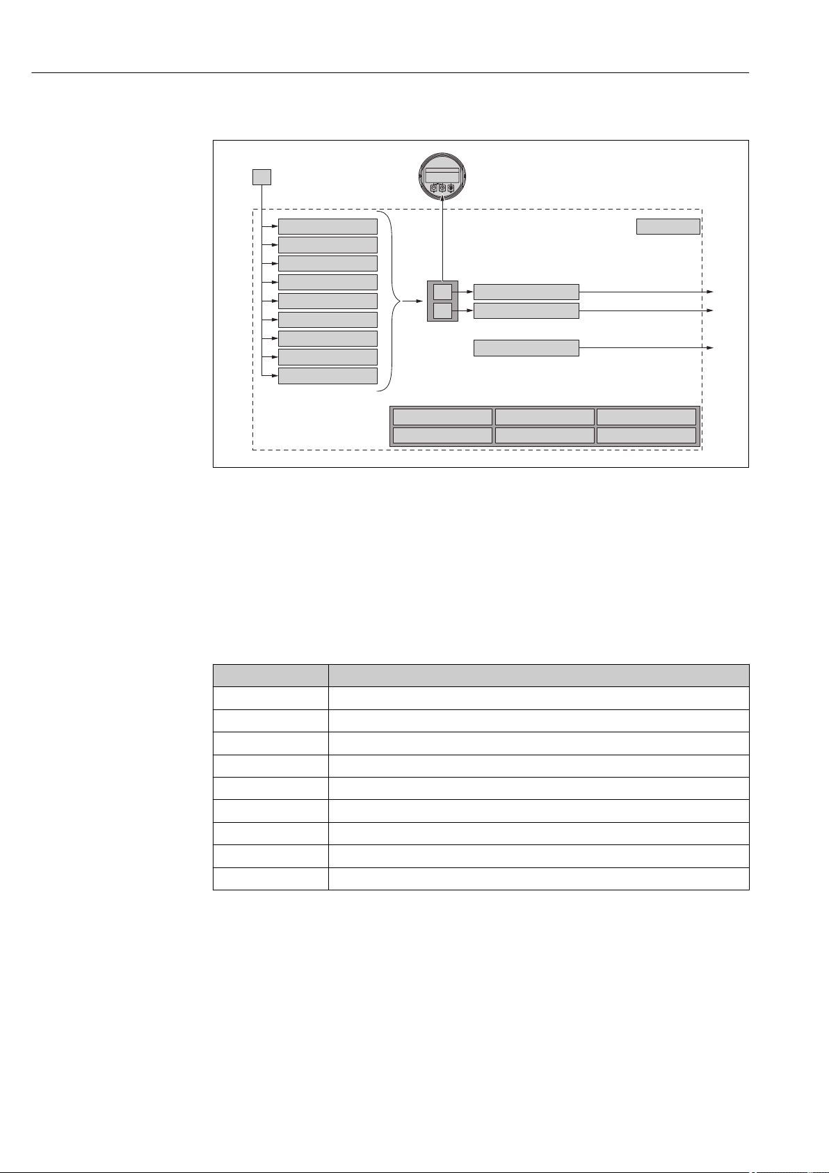
Integration into a FOUNDATION Fieldbus network Micropilot FMR51, FMR52 FOUNDATION Fieldbus
DIAGNOSTIC
PID ARITHMETIC SIGNAL_CHAR
S
RESOURCE
ANALOG_INPUT_1
ANALOG_INPUT_2
DI
ADV_SETUP
DATA_TRANSFER
EXPERT_INFO
SERVICE_INFO
DISPLAY
INPUT_SELECTOR
INTEGRATOR ANALOG_ALARM
EXPERT_CONFIG
SETUP
SERVICE_SENSOR
PV
SV
ESC
OPEN
OPEN
E
Device_01 F
mm
4841.000
9.4.2 Block configuration when device is delivered
A0017217
17 Block configuration when device is delivered
S Sensor
PV Primary value: Level linearized
SV Secondary value: Distance
9.5 Assignment of the measured values (CHANNEL) in an AI Block
The input value of an Analog Input Block is defined by the CHANNEL parameter.
Channel Measured value
0 Uninitialized
211 Terminal voltage
773 Analog output advance diagnostics 1
774 Analog output advance diagnostics 2
32786 Absolute echo amplitude
32856 Distance
32885 Elektronic temperature
32949 Level linearized
33044 Relative echo amplitude
9.6 Index tables of Endress+Hauser parameters
The following tables list the manufacturer-specific device parameters for the Resource
Blocks. For the FOUNDATION Fieldbus parameters, see the document BA062S "Guidline FOUNDATION Fieldbus Function Blocks", which can be downloaded from
www.endress.com.
64 Endress+Hauser
Page 65

Micropilot FMR51, FMR52 FOUNDATION Fieldbus Integration into a FOUNDATION Fieldbus network
9.6.1 Setup Transducer Block
Name Label Index Data type Size (Bytes) Storage Class Write access MODE_BLK
operating_mode Operating mode 15 ENUM16 2 Static Maintenance OOS
distance_unit Distance unit 16 ENUM16 2 Static Maintenance OOS
tank_type Tanktyp 17 ENUM16 2 Static Maintenance OOS
tube_diameter Tube diameter 18 FLOAT 4 Static Maintenance OOS
bin_type Bin type 19 ENUM16 2 Static Maintenance OOS
solid_filling_speed_range Max. filling speed solid 20 ENUM16 2 Static Maintenance OOS
solid_draining_speed_rangeMax. draining speed solid 21 ENUM16 2 Static Maintenance OOS
medium_group Medium group 22 ENUM16 2 Static Maintenance OOS
empty_calibration Empty calibration 23 FLOAT 4 Static Maintenance OOS
full_calibration Full calibration 24 FLOAT 4 Static Maintenance OOS
level_unit_ro Level unit 25 ENUM16 2 Static Maintenance OOS
PrimLevOut Primary Value 26 Standard 5 Dynamic
output_unit_after_lineariza
tion
filtered_distance Distance 28 Standard 5 Dynamic
signal_quality Signalqualität 29 ENUM16 2 Dynamic
confirm_distance Confirm distance 30 ENUM16 2 Static Maintenance OOS
mapping_start_point Mapping start point 31 FLOAT 4 Static Maintenance OOS
mapping_end_point Mapping end point 32 FLOAT 4 Static Maintenance OOS
end_map_ampl End map amplitude 33 FLOAT 4 Static Maintenance OOS
map_end_x Present mapping 34 FLOAT 4 Dynamic
map_end_y Map end Y 35 FLOAT 4 Dynamic
record_map Record map 36 ENUM16 2 Static Maintenance OOS
prepare_recording_map Prepare recording map 37 ENUM16 2 Static Development OOS
end_of_mapping End of mapping 38 ENUM16 2 Static Maintenance OOS
empty_scale 39 FLOAT 4 Static Maintenance OOS
full_scale 40 FLOAT 4 Static Maintenance OOS
empty_distance Tank/silo height 41 FLOAT 4 Static Maintenance OOS
sw_option_active_overview Software option overview 42 BIT_ENUM32 4
sensor_type_ro Sensor type 43 ENUM16 2 Static Service OOS
medium_type Medium type 44 ENUM16 2 Static Service OOS
decimal_places_menu Decimal places menu 45 ENUM16 2 Static Maintenance AUTO
evaluation_mode_ro Evaluation mode 46 ENUM16 2 Dynamic Maintenance OOS
access_status_tooling Access status tooling 47 ENUM16 2 Dynamic
locking_status Locking status 48 BIT_ENUM16 2 Dynamic
Unit after linearization 27 ENUM16 2 Static Maintenance
9.6.2 Advanced Setup Transducer Block
Name Label Index Data type Size (Bytes) Storage Class Write access MODE_BLK
medium_type Medium type 15 ENUM16 2 Static Service OOS
medium_property Medium property 16 ENUM16 2 Static Maintenance OOS
Endress+Hauser 65
Page 66

Integration into a FOUNDATION Fieldbus network Micropilot FMR51, FMR52 FOUNDATION Fieldbus
Name Label Index Data type Size (Bytes) Storage Class Write access MODE_BLK
calculated_dc_value_ee Calculated DC value 17 FLOAT 4 Dynamic Production AUTO
liquid_filling_speed_range Max. filling speed liquid 18 ENUM16 2 Static Maintenance OOS
liquid_draining_speed_rangeMax. draining speed liquid 19 ENUM16 2 Static Maintenance OOS
advanced_process_conditionsAdvanced process
conditions
level_unit Level unit 21 ENUM16 2 Static Maintenance OOS
blocking_distance Blocking distance 22 FLOAT 4 Static Maintenance OOS
level_correction Level correction 23 FLOAT 4 Static Maintenance OOS
empry_distance Tank/silo height 24 FLOAT 4 Static Maintenance OOS
linearization_type Linearization type 25 ENUM16 2 Static Maintenance OOS
unit_after_linearization Unit after linearization 26 ENUM16 2 Static Maintenance OOS
free_text Free text 27 STRING Static Maintenance AUTO
maximum_value Maximum value 28 FLOAT 4 Static Maintenance OOS
level_linearized_ds Level linearized 29 Standard 5 Dynamic
diameter Diameter 30 FLOAT 4 Static Maintenance OOS
intermediate_height Intermediate height 31 FLOAT 4 Static Maintenance OOS
table_number Table number 32 UINT8 1 Static Maintenance OOS
table_mode Table mode 33 ENUM16 2 Static Maintenance OOS
activate_table Tabelle aktivieren 34 ENUM16 2 Static Maintenance OOS
custom_table_sel_level Level 67 FLOAT 4 Static Maintenance OOS
custom_table_sel_value Customer value 68 FLOAT 4 Static Maintenance OOS
level_semiautomatic Level 69 FLOAT 4 Dynamic
output_echo_lost Output echo lost 70 ENUM16 2 Static Maintenance OOS
value_echo_lost Value echo lost 71 FLOAT 4 Static Maintenance OOS
ramp_at_echo_lost Ramp at echo lost 72 FLOAT 4 Static Maintenance OOS
switch_output_function Switch output function 73 ENUM16 2 Static Maintenance OOS
assign_status Assign status 74 ENUM16 2 Static Maintenance OOS
assign_limit Assign limit 75 ENUM16 2 Static Maintenance OOS
assign_diag_behavior Assign diagnostic behavior 76 ENUM16 2 Static Maintenance OOS
switch_on_value Switch-on value 77 FLOAT 4 Static Maintenance OOS
switch_on_delay Switch-on delay 78 FLOAT 4 Static Maintenance OOS
switch_off_value Switch-off value 79 FLOAT 4 Static Maintenance OOS
switch_off_delay Switch-off delay 80 FLOAT 4 Static Maintenance OOS
switch_output_failure_modeFailure mode 81 ENUM16 2 Static Maintenance OOS
20 ENUM16 2 Static Maintenance OOS
switch_status Switch status 82 ENUM16 2 Dynamic
invert_output_signal Invert output signal 83 ENUM16 2 Static Maintenance OOS
9.6.3 Display Transducer Block
Name Label Index Data type Size (Bytes) Storage Class Write access MODE_BLK
locking_status_display Locking status 15 ENUM16 2 Dynamic
access_status_display Access status display 16 ENUM16 2 Dynamic
66 Endress+Hauser
Page 67

Micropilot FMR51, FMR52 FOUNDATION Fieldbus Integration into a FOUNDATION Fieldbus network
Name Label Index Data type Size (Bytes) Storage Class Write access MODE_BLK
access_code_for_display Enter access code 17 UINT16 2 Static Operator AUTO
define_access_code Freigabecode definieren 18 UINT16 2 Static Maintenance AUTO
language Language 19 ENUM16 2 Static Operator AUTO
foramt_display Format display 20 ENUM16 2 Static Operator AUTO
value_1_display Value 1 display 21 ENUM16 2 Static Maintenance AUTO
decimal_places_1 Decimal places 1 22 ENUM16 2 Static Maintenance AUTO
value_2_display Value 2 display 23 ENUM16 2 Static Maintenance AUTO
decimal_places_2 Decimal places 2 24 ENUM16 2 Static Maintenance AUTO
value_3_display Value 3 display 25 ENUM16 2 Static Maintenance AUTO
decimal_places_3 Decimal places 3 26 ENUM16 2 Static Maintenance AUTO
value_4_display Value 4 display 27 ENUM16 2 Static Maintenance AUTO
decimal_places_4 Decimal places 4 28 ENUM16 2 Static Maintenance AUTO
display_interval Display interval 29 FLOAT 4 Static Operator AUTO
display_damping Display damping 30 FLOAT 4 Static Maintenance AUTO
header Header 31 ENUM16 2 Static Maintenance AUTO
header_text Header text 32 STRING 12 Static Maintenance AUTO
display_separator Separator 33 ENUM16 2 Static Maintenance AUTO
number_format Zahlenformat 34 ENUM16 2 Static Maintenance AUTO
decimal_places_menu Decimal places menu 35 ENUM16 2 Static Maintenance AUTO
contrast_display Contrast display 36 FLOAT 4 Static Operator AUTO
backlight Backlight 37 ENUM16 2 Static Operator AUTO
operating_time Operating time 38 STRING 14 Dynamic
last_backup Last backup 39 STRING 14 Static Production AUTO
configuration_management Configuration management 40 ENUM16 2 Static Maintenance AUTO
comparison_result Comparison result 41 ENUM16 2 Static Production AUTO
9.6.4 Diagnostic Transducer Block
Name Label Index Data type Size (Bytes) Storage Class Write access MODE_BLK
actual diagnostics Actual diagnostics 15 UINT32 4 Dynamic
present_timestamp Timestamp 16 STRING 14 Dynamic
previous diagnostics Letzte Diagnose 17 UINT32 4 Dynamic
previous_timestamp Timestamp 18 STRING 14 Dynamic
operating_time_from_restartOperating time from restart 19 STRING 14 Dynamic
operating_time Operating time 20 STRING 14 Dynamic
diagnostics_1 Diagnostics 1 21 UINT32 4 Dynamic
diag_1_timestamp Timestamp 22 STRING 14 Dynamic
diagnostics_2 Diagnostics 2 23 UINT32 4 Dynamic
diag_2_timestamp Timestamp 24 STRING 14 Dynamic
diagnostics_3 Diagnostics 3 25 UINT32 4 Dynamic
diag_3_timestamp Timestamp 26 STRING 14 Dynamic
diagnostics_4 Diagnostics 4 27 UINT32 4 Dynamic
Endress+Hauser 67
Page 68

Integration into a FOUNDATION Fieldbus network Micropilot FMR51, FMR52 FOUNDATION Fieldbus
Name Label Index Data type Size (Bytes) Storage Class Write access MODE_BLK
diag_4_timestamp Timestamp 28 STRING 14 Dynamic
diagnostics_5 Diagnostics 5 29 UINT32 4 Dynamic
diag_5_timestamp Timestamp 30 STRING 14 Dynamic
filter_options Filter options 31 ENUM8 1 Static Maintenance AUTO
clear_event_list Clear event list 32 ENUM16 2 Static Service AUTO
simulation_distance_ro Simulation distance 33 ENUM16 2 Static Development AUTO
value_of_simulated_distanceVaue of simulated distance 34 FLOAT 4 Static Maintenance AUTO
assign_sim_meas Assign measurement
variable
sim_value_process_variableValue process variable 36 FLOAT 4 Static Maintenance OOS
switch_output_simulation Switch output simulation 37 ENUM16 2 Static Maintenance OOS
sim_switch_status Switch status 38 ENUM16 2 Static Maintenance AUTO
simulation_device_alarm Simulation device alarm 39 ENUM16 2 Static Maintenance OOS
simulation_diagnostic_eventSimulation diagnostic event 40 UINT32 4 Static Service OOS
start_device_check Start device check 41 ENUM16 2 Static Maintenance AUTO
result_device_check Result device check 42 ENUM16 2 Static Development AUTO
last_check_time Last check time 43 STRING 14 Dynamic
level_signal Level signal 44 ENUM16 2 Static Development AUTO
device_check_timestamp Timestamp 45 UINT32 14 Static Development AUTO
assign_channel_1 Assign channel 1 54 ENUM16 2 Static Maintenance AUTO
assign_channel_2 Assign channel 2 55 ENUM16 2 Static Maintenance AUTO
assign_channel_3 Assign channel 3 56 ENUM16 2 Static Maintenance AUTO
assign_channel_4 Assign channel 4 57 ENUM16 2 Static Maintenance AUTO
logging_interval Logging interval 58 FLOAT 4 Static Maintenance AUTO
clear_logging_data Clear logging data 59 ENUM16 2 Static Maintenance AUTO
alarm_delay Alarm delay 60 FLOAT 4 Static Maintenance AUTO
35 ENUM16 4 Static Maintenance OOS
9.6.5 Expert Configuration Transducer Block
The parameters of the Expert Configuration Transducer Block are described in
GP01017F: "Micropilot FMR5x - Description of Device Parameters - FOUNDATION
Fieldbus"
Name Label Index Data type Size (Bytes) Storage Class Write access MODE_BLK
locking status Locking status 15 ENUM16 2
access_status_tooling Access status tooling 16 ENUM16 2
enter_access_code Enter access code 17 UINT16 2 Static Operator AUTO
distance_unit_ro Distance unit 18 ENUM16 2 Static Maintenance OOS
operating_mode_ro Operating mode 19 ENUM16 2 Static Maintenance OOS
free_field_special Free field special 20 ENUM16 2 Static Maintenance OOS
sensor_type Sensor type 21 ENUM16 2 Static Service OOS
distance_offset Distance offset 22 FLOAT 4 Static Maintenance OOS
level_unit_ro Level unit 23 ENUM16 2 Static Maintenance OOS
68 Endress+Hauser
Page 69

Micropilot FMR51, FMR52 FOUNDATION Fieldbus Integration into a FOUNDATION Fieldbus network
Name Label Index Data type Size (Bytes) Storage Class Write access MODE_BLK
level_limit_mode Level limit mode 24 ENUM16 2 Static Maintenance OOS
level_high_limit High limit 25 FLOAT 4 Static Maintenance OOS
level_low_limit Low limit 26 FLOAT 4 Static Maintenance OOS
output_mode Output mode 27 ENUM16 2 Static Maintenance OOS
filter_dead_time Dead time 28 FLOAT 4 Static Maintenance OOS
integration_time Integration time 29 FLOT 4 Static Maintenance OOS
velocity_filter Geschwindigkeitfilter 30 ENUM16 2 Static Service OOS
gpc_mode GPC mode 31 ENUM16 2 Static Maintenance OOS
external_pressure_selector External pressure selector 32 ENUM16 2 Static Maintenance OOS
gas_phase_compens_factor Gas phase compensation factor 33 FLOAT 4 Static Maintenance OOS
reference_distance Reference distance 34 FLOAT 4 Static Maintenance OOS
present_reference_distance Present reference distance 35 FLOAT 4 Dynamic
reference_echo_threshold Reference echo threshold 36 FLOAT 4 Static Maintenance OOS
const_gpc_factor Const. GPC factor 37 FLOAT 4 Static Maintenance OOS
external_pressure External pressure 38 FLOAT 4 Static Development AUTO
start_self_check Start self check 39 ENUM16 2 Static Maintenance AUTO
result_self_check Result self check 40 ENUM16 2 Static Development AUTO
delay_time_echo_lost Delay time echo lost 41 FLOAT 4 Static Maintenance OOS
safety_distance Sicherheitsdistanz 42 FLOAT 4 Static Maintenance OOS
in_safety_distance In safety distance 43 ENUM16 2 Static Maintenance OOS
acknowledge_alarm Acknowledge alarm 44 ENUM16 2 Static Maintenance AUTO
evaluation_mode Evaluation mode 45 ENUM16 2 Static Maintenance OOS
history_reset History reset 46 ENUM16 2 Static Maintenance OOS
history_learning_control History learning control 47 ENUM16 2 Static Maintenance OOS
history_learning History learning 48 ENUM16 2 Static Maintenance OOS
level_external_input_1 Level external input 1 49 ENUM16 2 Static Maintenance OOS
function_input_1_level Function input 1 level 50 ENUM16 2 Static Maintenance OOS
fixed_value_input_1 Fixed value input 1 51 FLOAT 4 Static Maintenance OOS
binary_input_1_level_control Binary input 1 level control 52 ENUM16 2 Static Maintenance OOS
level_external_input_2 Level external input 2 53 ENUM16 2 Static Maintenance OOS
function_input_2_level Function input 2 level 54 ENUM16 2 Static Maintenance OOS
fixed_value_input_2 Fixed value input 2 55 FLOAT 4 Static Maintenance OOS
binary_input_2_level_control Binary input 2 level control 56 ENUM16 2 Static Maintenance OOS
control_measurement Control measurement 57 ENUM16 2 Static Maintenance OOS
measurement_on Measurement 58 ENUM16 2 Static Maintenance OOS
sensor_module Sensor module 59 ENUM16 2 Static Development AUTO
sensor_module_ee Sensor module 60 ENUM16 2 Static Production OOS
decimal_places_menu_ro Decimal places menu 61 ENUM16 2 Static Maintenance AUTO
sw_option_active_overview Software option active overview 62 BIT_ENUM32 4
fieldbus_type Feldbustyp 63 ENUM8 1
medium_type_ro Medium type 64 ENUM16 2 Static Service OOS
Endress+Hauser 69
Page 70

Integration into a FOUNDATION Fieldbus network Micropilot FMR51, FMR52 FOUNDATION Fieldbus
9.6.6 Expert Information Transducer Block
The parameters of the Expert Information Transducer Block are described in
GP01017F: "Micropilot FMR5x - Description of Device Parameters - FOUNDATION
Fieldbus"
Name Label Index Data type Size (Bytes) Storage Class Write access MODE_BLK
abs_echo_ampl Absolute echo amplitude 15 Standard 5
rel_echo_ampl Relative echo amplitude 16 Standard 5 Dynamic
rel_eop_ampl Tank bottom echo amplitude 17 Standard 5 Dynamic
noise_signal_val Noise of signal 18 FLOAT 4 Dynamic
electronic_temperature Electronic temperature 19 Standard 5 Dynamic
found_echoes Found echoes 20 ENUM16 2 Dynamic
temperature_unit Temperature unit 21 ENUM16 2 Static Maintenance OOS
max_electr_temp Max. electronic temperature 22 FLOAT 4 Static Development AUTO
application_parameter Application parameter 23 ENUM16 2 Dynamic
time_max_electr_temp Time max. electronics temperature 24 STRING 14 Dynamic
measurement_frequency Measurement frequency 25 FLOAT 4 Dynamic
min_electr_temp Min. electronics temperature 26 FLOAT 4 Static Development AUTO
time_min_electr_temp Time min. electronics temperaturer 27 STRING 14 Dynamic
reset_min_max_temp Reset min/max. Temp. 28 ENUM16 2 Static Service AUTO
used_calculation Used calculation 29 ENUM16 2 Dynamic
tank_trace_state Status Tanktrace 30 ENUM16 2 Dynamic
max_draining_speed Max. draining speed 31 FLOAT 4 Static Development AUTO
max_filling_speed Max. filling speed 32 FLOAT 4 Static Entwicklung AUTO
time_max_level Time max. level 33 STRING 14 Dynamic
max_level_value Max. level value 34 FLOAT 4 Static Development AUTO
time_min_level Time min. level 35 STRING 14 Dynamic
min_level_value Min. level 36 FLOAT 4 Static Development AUTO
reset_min_max Reset min./max. 37 ENUM16 2 Static Service AUTO
appl_param_changed_flags Application parameter 38 UINT16 2 Static Production AUTO
terminal_voltage_ds Terminal voltage 39 Standard 5 Dynamic
area_of_incoupling Area of incoupling 40 Standard 5 Dynamic
linearization_type_ro Linearization type 41 ENUM16 2 Static Maintenance OOS
operating_mode Operating mode 42 ENUM16 2 Static Maintenance OOS
decimal_places_menu_ro Decimal places menu 43 ENUM16 2 Static Maintenance AUTO
activat_sw_option Activate SW option 44 UINT32 4 Static Maintenance AUTO
sw_option_active_overview Sw option active overview 45 BIT_ENUM32 4 Dynamic
debug_status 107 UINT8 1 Dynamic x AUTO
9.6.7 Service Sensor Transducer Block
The parameters of the Service Sensor Transducer Block can only be operated by
authorized Endress+Hauser service personnel.
70 Endress+Hauser
Page 71

Micropilot FMR51, FMR52 FOUNDATION Fieldbus Integration into a FOUNDATION Fieldbus network
9.6.8 Service Information Transducer Block
The parameters of the Service Information Transducer Block can only be operated by
authorized Endress+Hauser service personnel.
9.6.9 Advanced Diagnostics Transducer Block
The parameters of the Advanced Diagnostics Transducer Block are described in
GP01017F: "Micropilot FMR5x - Description of Device Parameters - FOUNDATION
Fieldbus"
Name Label Index Data type Size (Bytes) Storage Class Write access MODE_BLK
assign_diag_signal_ad1 Assign diagnostic signal 1 15 ENUM16 2 Static Maintenance OOS
link_ad1_to Link AD1 to 16 ENUM16 2 Static Maintenance OOS
linking_logic_ad1 Linking logic AD1 17 ENUM16 2 Static Maintenance OOS
sample_time_ad1 Sample time 1 18 UINT16 2 Static Maintenance OOS
calc_type_ad1 Calculation type 1 19 ENUM16 2 Static Maintenance OOS
check_mode_ad1 Check mode 1 20 ENUM16 2 Static Maintenance OOS
calculation_unit_ad1 Calculation unit 1 21 ENUM16 2 Static Operator OOS
upper_limit_ad1 Upper limit 1 22 FLOAT 4 Static Maintenance OOS
lower_limit_ad1 Lower limit 1 23 FLOAT 4 Static Maintenance OOS
hysteresis_ad1 Hysteresis 1 24 FLOAT 4 Static Maintenance OOS
max_value_ad1 Maximum value 1 25 FLOAT 4 Dynamic
min_value_ad1 Minimum value 1 26 FLOAT 4 Dynamic
reset_min_max_ad1 Reset min./max. 1 27 ENUM16 2 Static Maintenance AUTO
assign_status_sig_ad1 Assign status signal to AD event 1 28 ENUM16 2 Static Maintenance OOS
assign_event_behaviour_ad1 Assign event behaviourn 1 29 ENUM16 2 Static Maintenance OOS
alarm_delay_ad1 Alarm delay 30 FLOAT 4 Static Maintenance OOS
assign_diag_ signal_ad2 Assign diagnostic signal 2 31 ENUM16 2 Static Maintenance OOS
link_ad2_to Link AD2 to 32 ENUM16 2 Static Maintenance OOS
linking_logic_ad2 Linking logic AD2 33 ENUM16 2 Static Maintenance OOS
sample_time_ad2 Sample time 2 34 UINT16 2 Static Maintenance OOS
calc_type_ad2 Calculation type 2 35 ENUM16 2 Static Maintenance OOS
check_mode_ad2 Check mode 2 36 ENUM16 2 Static Maintenance OOS
calculation_unit_ad2 Calculation unit 2 37 ENUM16 2 Static Operator OOS
upper_limit_ad2 Upper limit 2 38 FLOAT 4 Static Maintenance OOS
lower_limit_ad2 Lower limit 2 39 FLOAT 4 Static Maintenance OOS
hysteresis_ad2 Hysteresis 2 40 FLOAT 4 Static Maintenance OOS
max_value_ad2 Maximum value 2 41 FLOAT 4 Dynamic
min_value_ad2 Minimum value 2 42 FLOAT 4 Dynamic
reset_min_max_ad2 Reset min./max. 2 43 ENUM16 2 Static Maintenance AUTO
assign_status_sig_ad2 Assign status signal to AD event 2 44 ENUM16 2 Static Maintenance OOS
assign_event_behaviour_ad2 Assign event behaviour 2 45 ENUM16 2 Static Maintenance OOS
alarm_delay_ad2 Alarm delay 2 46 FLOAT 4 Static Maintenance OOS
Endress+Hauser 71
Page 72

Integration into a FOUNDATION Fieldbus network Micropilot FMR51, FMR52 FOUNDATION Fieldbus
9.7 Methods
The FOUNDATION Fieldbus Specification includes the use of methods to make device
operation easier. A method is a sequence of interactive steps to be carried out in the
specified order so as to configure certain device functions.
The following methods are available for the device:
• Restart
This method is located in the Resource Block and directly prompts the setting of the
Device reset parameter. This resets the device configuration to a defined state.
• ENP Restart
This method is located in the Resource Block and directly prompts the setting of the
parameters of the Electronic Name Plate (ENP).
• Setup
This method is located in the SETUP Transducer Block and allows to set the most
important parameters in this block for device configuration (measuring units, type of
tank or vessel, type of medium, empty and full calibration).
• Linearization
This method is located in the ADV_SETUP Transducer Block and allows to manage the
linearization table by which the measured value is converted into volume, mass or flow.
• Self Check
This method is located in the EXPERT_CONFIG Transducer Block and prompts the device
self check parameters.
72 Endress+Hauser
Page 73
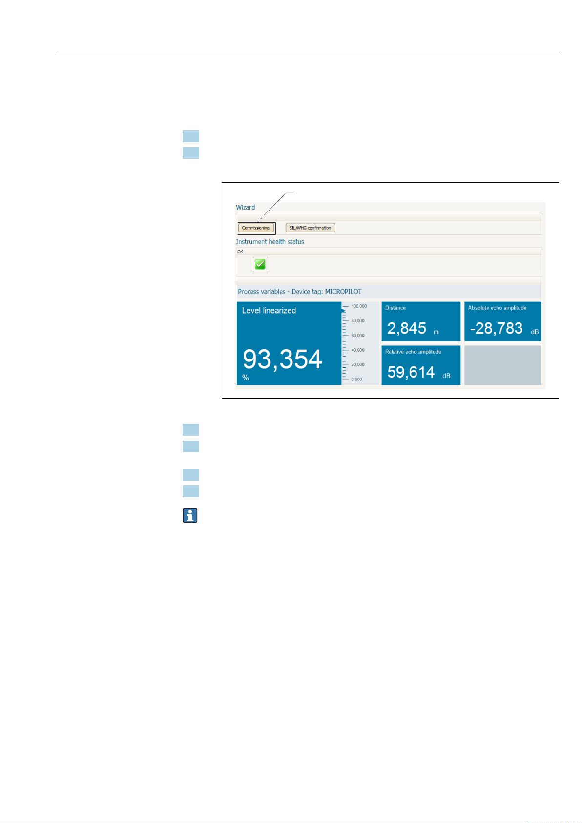
Micropilot FMR51, FMR52 FOUNDATION Fieldbus Commissioning via wizard
1
10 Commissioning via wizard
A wizard guiding the user through the initial setup is available in FieldCare and
DeviceCare.
1. Connect the device to FieldCare or DeviceCare → 44.
2. Open the device in FieldCare or DeviceCare.
The dashboard (home page) of the device appears:
A0027720
1 "Commissioning" button calls up the wizard.
3. Click on "Commissioning" to call up the wizard.
4. Enter or select the appropriate value for each parameter. These values are
immediately written to the device.
5. Click "Next" to switch to the next page.
6. After finishing the last page, click "End of sequence" to close the wizard.
If the wizard is cancelled before all necessary parameters have been set, the device
may be in an undefined state. A reset to the default settings is recommended in this
case.
Endress+Hauser 73
Page 74
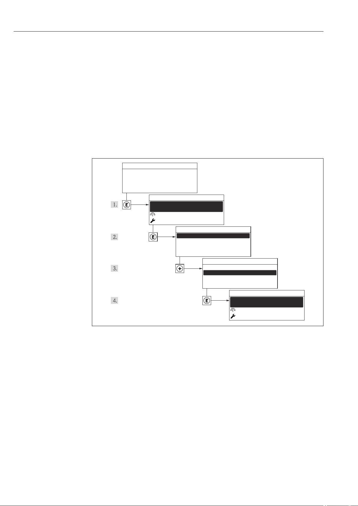
Commissioning via operating menu Micropilot FMR51, FMR52 FOUNDATION Fieldbus
X X XX X X XX X
20.50
Operation
Setup
Main menu
0104-1
Language
English
Español
Français
Language
English
Deutsch
Ã
0104-1
Ã
Español
Français
Language
English
Deutsch
0104-1
Betrieb
Setup
Hauptmenü
Sprache
Deutsch
0104-1
XXXX
11 Commissioning via operating menu
11.1 Installation and function check
Make sure that all final checks have been completed before you start up your measuring
point:
• Checklist "Post-installation check" → 35
• Checklist "Post-connection check" → 41
11.2 Setting the operating language
Factory setting: English or ordered local language
A0013996
18 Using the example of the local display
74 Endress+Hauser
Page 75
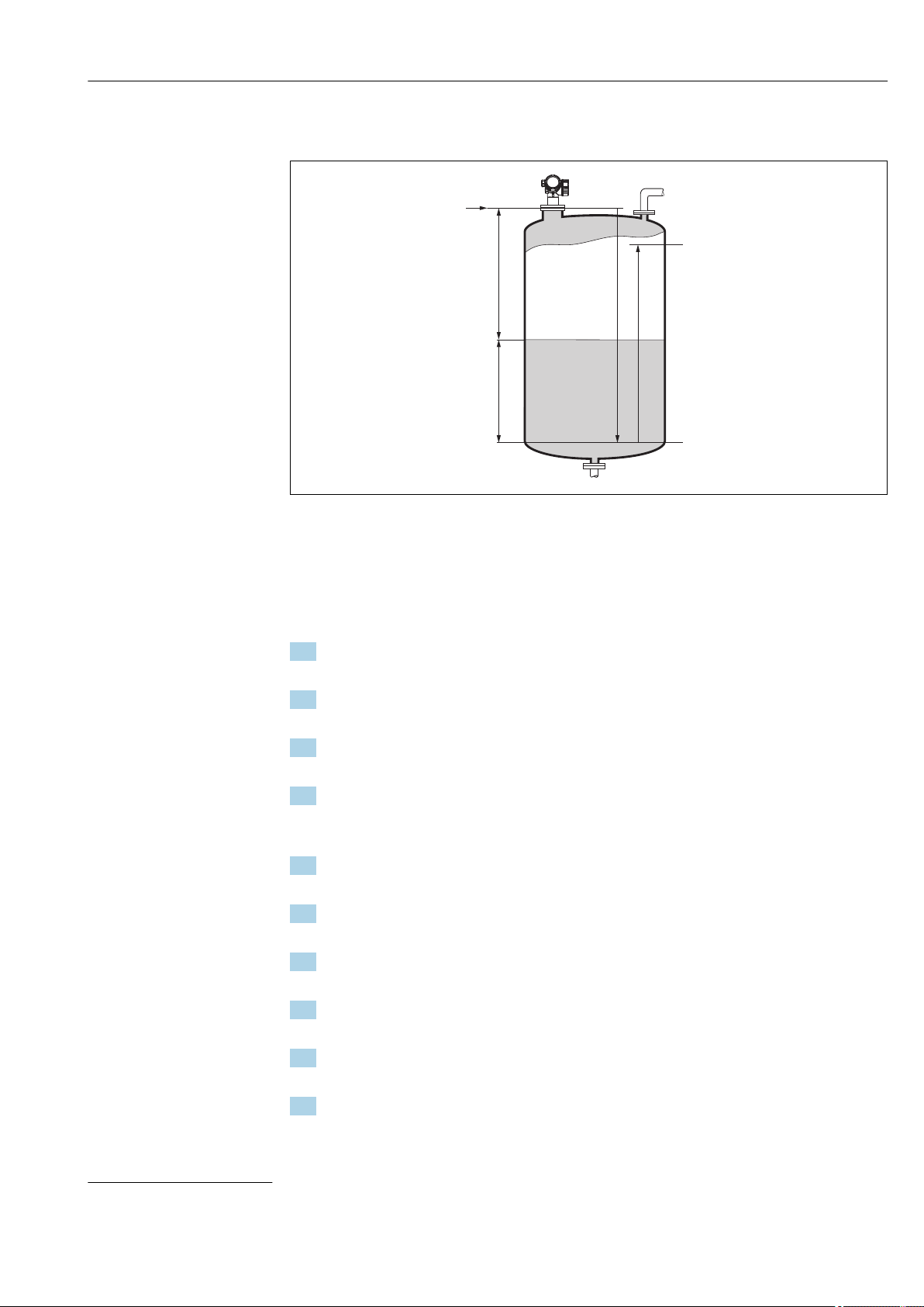
Micropilot FMR51, FMR52 FOUNDATION Fieldbus Commissioning via operating menu
F
L
D
E
100%
0%
R
11.3 Configuration of a level measurement
A0016933
19 Configuration parameters for level measurements in liquids
R Reference point of the measurement
D Distance
L Level
E Empty calibration (= zero)
F Full calibration (= span)
1. Navigate to: Setup → Device tag
Enter device tag.
2. Navigate to: Setup → Distance unit
Select distance unit.
3. Navigate to: Setup → Tank type
Select tank type.
4. For Tank type parameter = Bypass / pipe:
Navigate to: Setup → Tube diameter
Enter the diameter of the stilling well or bypass.
5. Navigate to: Setup → Medium group
Specify medium group: (Water based (DC >= 4) or Others)
6. Navigate to: Setup → Empty calibration
Enter empty distance E (Distance from reference point R to the 0% level)
5)
.
7. Navigate to: Setup → Full calibration
Enter full distance F (Distance from the 0% to the 100% level).
8. Navigate to: Setup → Level
Indicates the measrued level L.
9. Navigate to: Setup → Distance
Indicates the measured distance from the reference point R to the level L.
10. Navigate to: Setup → Signal quality
Indicates the quality of the evaluated level echo.
5) If, for example, the measuring range covers only an upper part of the tank (E << tank height), it is mandatory to enter the acutal tank height into
the "Setup → Advanced Setup → Level → Tank/silo height" parameter.
Endress+Hauser 75
Page 76

Commissioning via operating menu Micropilot FMR51, FMR52 FOUNDATION Fieldbus
11. When operating via local display:
Navigate to: Setup → Mapping → Confirm distance
Compare distance indicated on the display to real distance in order to start the
recording of an interference echo map.
12. When operating via operating tool:
Navigate to: Setup → Confirm distance
Compare distance indicated on the display to real distance in order to start the
recording of an interference echo map.
13. Navigate to: Setup → Advanced setup → Level → Level unit
Select level unit: %, m, mm, ft, in (Factory setting: %)
The response time of the device is preset by the Tank type parameter (→ 126).
More detailed settings are possible in the Advanced setup submenu.
76 Endress+Hauser
Page 77

Micropilot FMR51, FMR52 FOUNDATION Fieldbus Commissioning via operating menu
11.4 Recording the reference curve
After the configuration of the measurement it is recommended to record the current
envelope curve as a reference curve. The reference curve can be used later on in the
process for diagnostic purposes. To record the reference curve use the Save reference
curve parameter.
Navigation in the menu
Expert → Diagnostics → Envelope diagnostics → Save reference curve
Meaning of the options
• No
No action
• Yes
The current envelope curve is saved as reference curve.
In devices which have been delivered with software version 01.00.zz, this submenu is
only visible for the "Service" user role.
The reference curve can only be displayed in the envelope curve diagram of FieldCare
after it has been loaded from the device into FieldCare. This is performed by the "Load
Reference Curve" function in FieldCare.
20 The "Load Reference Curve" function
Endress+Hauser 77
Page 78

Commissioning via operating menu Micropilot FMR51, FMR52 FOUNDATION Fieldbus
11.5 Configuration of the on-site display
11.5.1 Factory settings of the on-site display
Parameter Factory setting
Format display 1 value, max. size
Value 1 display Level linearized
Value 2 display None
Value 3 display None
Value 4 display None
11.5.2 Adjustment of the on-site display
The on-site display can be adjusted in the following submenu:
Setup → Advanced setup → Display
78 Endress+Hauser
Page 79

Micropilot FMR51, FMR52 FOUNDATION Fieldbus Commissioning via operating menu
11.6 Configuration management
After commissioning, you can save the current device configuration, copy it to another
measuring point or restore the previous device configuration. You can do so using the
Configuration management parameter and its options.
Navigation path in the operating menu
Setup → Advanced setup → Configuration backup display → Configuration management
Meaning of the options
• Cancel
No action is executed and the user exits the parameter.
• Execute backup
A backup copy of the current device configuration in the HistoROM (built-in in the
device) is saved to the display module of the device. The backup copy comprises the
transmitter and sensor data of the device.
• Restore
The last backup copy of the device configuration is copied from the display module to the
HistoROM of the device. The backup copy comprises the transmitter and sensor data of
the device.
• Duplicate
The transmitter configuration is duplicated to another device using the transmitter
display module. The following parameters, which characterize the individual measuring
point are not included in the transmitted configuration:
Medium type
• Compare
The device configuration saved in the display module is compared to the current device
configuration of the HistoROM. The result of this comparison is displayed in the
Comparison result parameter.
• Clear backup data
The backup copy of the device configuration is deleted from the display module of the
device.
While this action is in progress, the configuration cannot be edited via the local
display and a message on the processing status appears on the display.
If an existing backup is restored to a different device using the Restore option, it may
occur that some device functionalities are no longer available. In some cases even a
device reset → 171 will not restore the original status.
In order to transmit a configuration to a different device, the Duplicate option should
always be used.
Endress+Hauser 79
Page 80

Commissioning via operating menu Micropilot FMR51, FMR52 FOUNDATION Fieldbus
11.7 Protection of the settings against unauthorized changes
There are two ways to protect the settings against unauthorized changes:
• Via parameter settings (software locking) → 48
• Via locking switch (hardware locking) → 50
80 Endress+Hauser
Page 81

Micropilot FMR51, FMR52 FOUNDATION Fieldbus Commissioning (block-based operation)
12 Commissioning (block-based operation)
12.1 Function check
Carry out a post-installation and a post-connection check as per the checklist before
commissioning the device:
• "Post-installation check" checklist → 35
• "Post-connection check" checklist → 41
12.2 Block configuration
12.2.1 Preparatory steps
1. Switch on the device.
2. Note the DEVICE_ID → 61.
3. Open the FOUNDATION Fieldbus configuration program.
4. Load Cff and device description files into the host system or the configuration
program. Make sure you are using the right system files.
5. Identify the device using the DEVICE_ID (see Point 2). Assign the desired tag name
to the device by means of the Pd-tag/FF_PD_TAG parameter.
12.2.2 Configuring the Resource Block
1. Open the Resource Block.
2. If necessary, disable the lock for device operation.
3. If necessary, change the block name. Factory setting: RS-xxxxxxxxxxx (RB2)
4. If necessary, assign a description to the block by means of the Tag Description/
TAG_DESC parameter.
5. If necessary, change other parameters as per the requirements.
12.2.3 Configuring the Transducer Blocks
The measurement and the display module are configured using the Transducer Blocks. The
general procedure is the same for all Transducer Blocks:
1. If necessary, change the block name.
2. Set the block mode to OOS by means of the Block Mode/MODE_BLK parameter,
TARGET element.
3. Configure the level measurement → 84.
4. Set the block mode to Auto by means of the Block Mode/MODE_BLK parameter,
TARGET element.
The block mode must be set to Auto for the measuring device to function correctly.
Endress+Hauser 81
Page 82
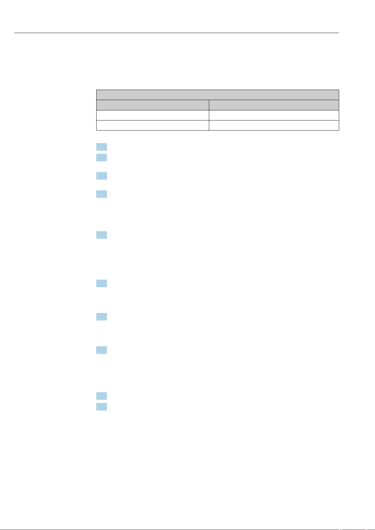
Commissioning (block-based operation) Micropilot FMR51, FMR52 FOUNDATION Fieldbus
12.2.4 Configuring the Analog Input Blocks
The device has 2 permanently instanced Analog Input Blocks that can be assigned as
required to the various process variables. If required, up to 5 Analog Input Blocks can be
instanced through the FOUNDATION Fieldbus configuration tool.
Default settings
Analog Input Block CHANNEL
AI 1 32949: Level linearized
AI 2 32856: Distance
1. If necessary, change the block name.
2. Set the block mode to OOS by means of the Block Mode/MODE_BLK parameter,
TARGET element.
3. Use the Channel/CHANNEL parameter to select the process variable which should
be used as the input value for the Analog Input Block.
4. Use the Transducer Scale/XD_SCALE parameter to select the desired unit and the
block input range for the process variable → 82. Make sure that the unit
selected suits the process variable selected. If the process variable does not suit the
unit, the Block Error/BLOCK_ERR parameter reports Block Configuration Error
and the block mode cannot be set to Auto.
5. Use the Linearization Type/L_TYPE parameter to select the type of linearization for
the input variable (factory setting: Direct). Make sure that the settings for the
Transducer Scale/XD_SCALE and Output Scale/ OUT_SCALE parameters are the
same for the Direct linearization type. If the values and units do not match, the Block
Error/BLOCK_ERR parameter reports Block Configuration Error and the block
mode cannot be set to Auto.
6. Enter the alarm and critical alarm messages by means of the High High Limit/
HI_HI_LIM, High Limit/HI_LIM, Low Low Limit/LO_LO_LIM and Low Limit/
LO_LIM parameters. The limit values entered must be within the value range
specified for the Output Scale/ OUT_SCALE parameter → 82.
7. Specify the alarm priorities by means of the High High Priority/HI_HI_PRI, High
Priority/ HI_PRI, Low Low Priority/LO_LO_PRI and Low Priority/LO_PRI
parameters. Reporting to the field host system only takes place with alarms with a
priority greater than 2.
8. Set the block mode to Auto using the Block Mode/MODE_BLK parameter, TARGET
element. For this purpose, the Resource Block and the Setup Transducer Block must
also be set to the Auto block mode.
12.2.5 Additional configuration
1. Link the function blocks and output blocks.
2. After specifying the active LAS, download all the data and parameters to the field
device.
12.3 Scaling of the measured value in an AI Block
If the type of linearisation L_TYPE = indirect has been selected in an AI block, the
measured value can be scaled within the block. The input range is defined by the
XD_SCALE parameter through its EU_0 and EU_100 elements. This range is mapped
linearly to the output ranged defined by the OUT_SCALE parameter through its EU_0 and
EU_100 elements.
82 Endress+Hauser
Page 83
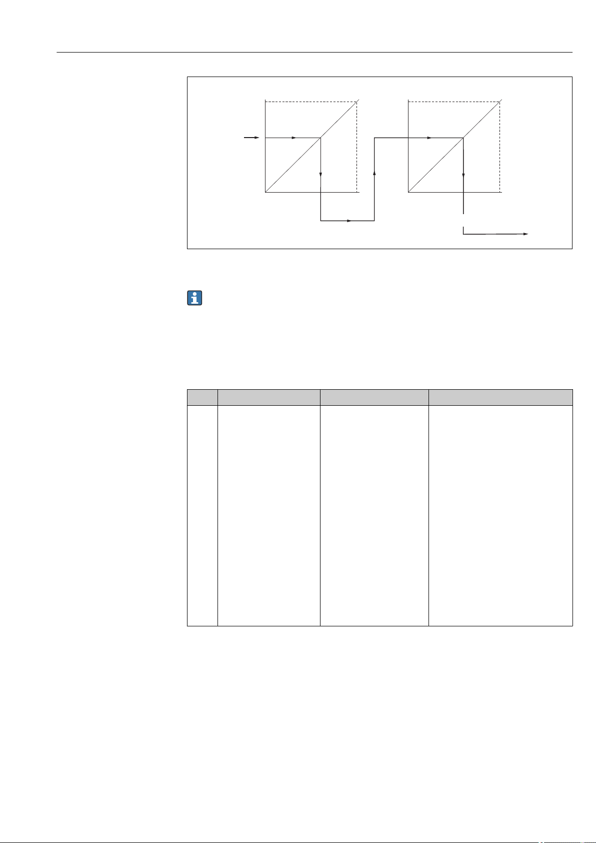
Micropilot FMR51, FMR52 FOUNDATION Fieldbus Commissioning (block-based operation)
0
1
0
1
EU_100
XD_SCALE OUT_SCALE
EU_0
EU_0
EU_100
OUT_VALUE
A0017338
21 Scaling of the measured value in an AI Block
• If you have selected the Direct mode for the L_TYPE parameter, you cannot change
the values and units for XD_SCALE and OUT_SCALE.
• The L_TYPE, XD_SCALE and OUT_SCALE parameters can only be changed in the
OOS block mode.
12.4 Language selection
Step Block Parameter Action
1 DISPLAY (TRDDISP) Language (language) Select language
Selection:
• 1268: Swedish
• 32805: Arabian
• 32824: Chinese simplified
• 32842: Czech
• 32881: Dutch
• 32888: English
• 32917: French
• 32920: German
• 32945: Italian
• 32946: Japanese
• 32948: Korean
• 33026: Polish
• 33027: Portuguese
• 33062: Russian
• 33083: Spanish
• 33103: Thai
• 33120: Vietnamese
• 33155: Bahasa
• 33166: Turkish
1) When ordering a device the set of available languages is defined. Refer to the product structure, feature
500 "Additional Operation Language".
1)
.
Endress+Hauser 83
Page 84
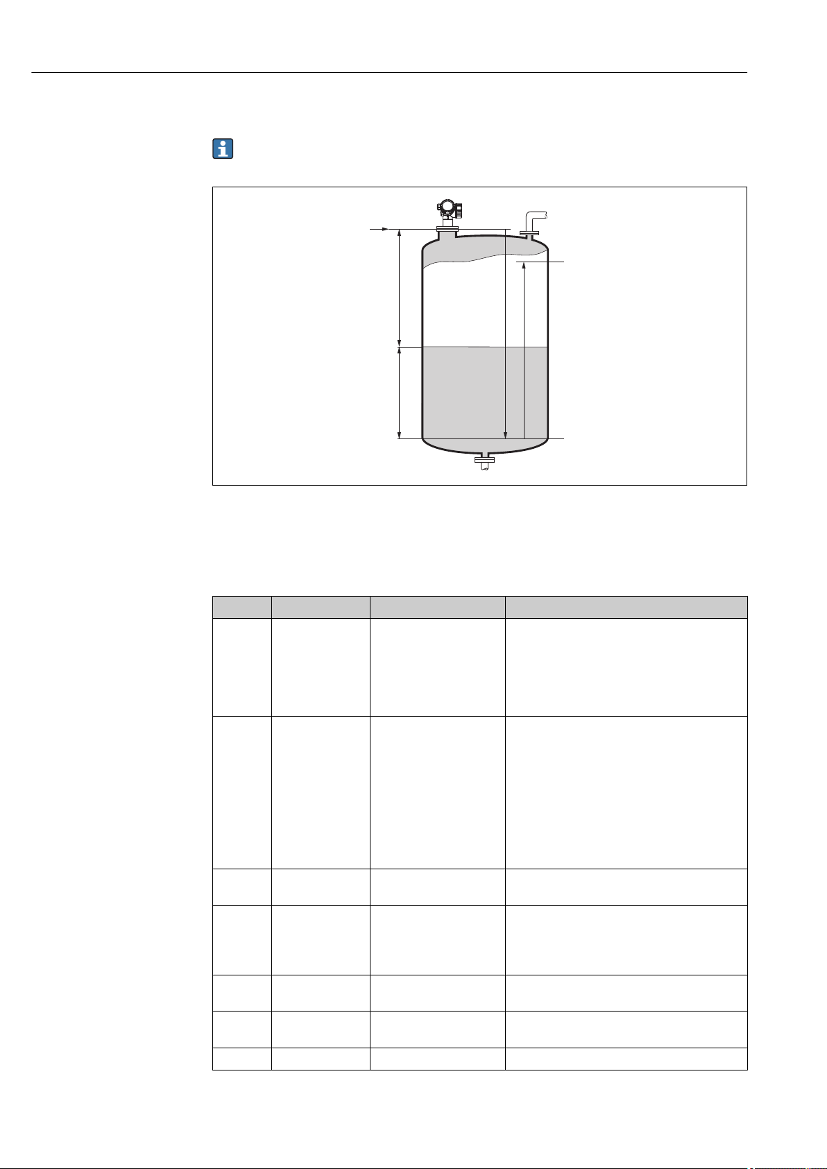
Commissioning (block-based operation) Micropilot FMR51, FMR52 FOUNDATION Fieldbus
F
L
D
E
100%
0%
R
12.5 Configuration of a level measurement
The Setup method can also be used to configure the measurement. It is called up via
the SETUP (TRDSUP) Transducer Block.
A0016933
R = Reference point of the measurement E = Empty calibration (= Zero point)
D = Distance F = Full calibration (= span)
L = Level
Step Block Parameter Action
1 SETUP (TRDSUP) Distance unit
(distance_unit)
2 SETUP (TRDSUP) Tank type (tank_type) Select tank type.
3 SETUP (TRDSUP) Tube diameter
(tube_diameter)
4 SETUP (TRDSUP) Medium group
(medium_group)
1)
5 SETUP (TRDSUP) Empty calibration
(empty_calibration)
6 SETUP (TRDSUP) Full calibration
(full_calibration)
7 SETUP (TRDSUP) Level (level) Displays the measured level L.
Select distance unit.
Selection:
• 1010: m
• 1013: mm
• 1018: ft
• 1019: in
Selection:
• 1271: Process vessel with agitator
• 1272: Process vessel standard
• 1273: Storage vessel
• 1274: Wave guide antenna
• 1279: Sphere
• 32816: Bypass / pipe
• 33013: Open channel
• 33094: Stilling well
Enter the diameter of the bypass or stilling well.
Select medium group.
Selection:
• 316: water based (DC>4)
• 256: other (DC≥ 1.9)
Enter the distance E between the reference point
R and the minimum level (0%).
Enter distance F between the minimum (0%) and
maximum (100%) level.
84 Endress+Hauser
Page 85
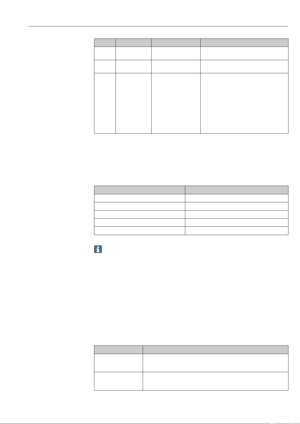
Micropilot FMR51, FMR52 FOUNDATION Fieldbus Commissioning (block-based operation)
Step Block Parameter Action
8 SETUP (TRDSUP) Distance
(filtered_dist_val)
9 SETUP (TRDSUP) Signal quality
(signal_quality)
10 SETUP (TRDSUP) Confirm distance
(confirm_distance)
1) only available for "Tank type" = "Bypass/pipe"
Displays the distance D between the reference
point R and the level L.
Displays the signal quality of the level echo.
Compare the displayed distance to the real
distance in order to start the recording of the
mapping curve.
Selection:
• 179: Manual map
• 32847: Factory map
• 32859: Distance ok
• 32860: Distance too big
• 32861: Distance too small
• 32862: Distance unknown
• 33100: Tank empty
12.6 Configuration of the on-site display
12.6.1 Factory settings of the on-site display for level measurements
Parameter Factory setting
Format display 1 value, max. size
Value 1 display Level linearized
Value 2 display None
Value 3 display None
Value 4 display None
The on-site display can be adjusted in the DISPLAY (TRDDISP) transducer block.
12.7 Configuration management
After commissioning, you can save the current device configuration, copy it to another
measuring point or restore the previous device configuration. You can do so using the
Configuration management parameter and its options.
Navigation path in the operating menu
Setup → Advanced setup → Conf.backup disp → Config. managem.
Block operation
Block: DISPLAY (TRDDISP)
Parameter: Configuration management (configuration_management)
Functions of the parameter options
Options Description
33097: Execute backup A backup copy of the current device configuration in the HistoROM is saved to the
display module of the device. The backup copy comprises the transmitter data of
the device.
33057: Restore The last backup copy of the device configuration is copied from the display module
to the HistoROM of the device. The backup copy comprises the transmitter data of
the device.
Endress+Hauser 85
Page 86

Commissioning (block-based operation) Micropilot FMR51, FMR52 FOUNDATION Fieldbus
Options Description
33838: Duplicate The transmitter configuration from another device is duplicated to the device using
the display module.
265: Compare The device configuration saved in the display module is compared to the current
device configuration of the HistoROM.
32848: Clear backup data The backup copy of the device configuration is deleted from the display module of
the device.
HistoROM
A HistoROM is a "non-volatile" device memory in the form of an EEPROM.
While this action is in progress, the configuration cannot be edited via the local
display and a message on the processing status appears on the display.
86 Endress+Hauser
Page 87
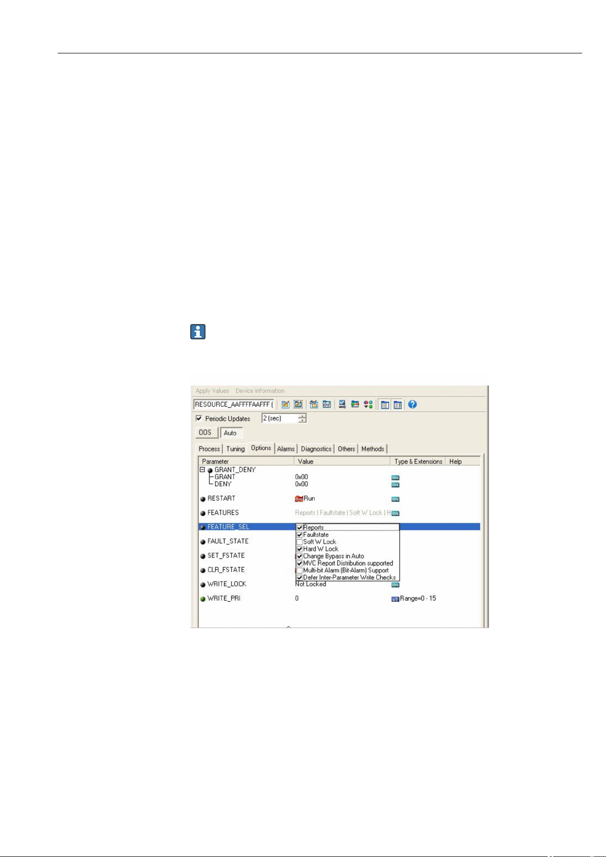
Micropilot FMR51, FMR52 FOUNDATION Fieldbus Commissioning (block-based operation)
12.8 Configuration of the event behavior according to the
FOUNDATION Fieldbus specification FF912
The device complies with the FOUNDATION Fieldbus specification FF912. This has among other things - the following consequences:
• The diagnsotic category according to NAMUR recommendation NE107 is transmitted via
the fieldbus in a manufacturer-independent form:
– F: Failure
– C: Function check
– S: Out of specification
– M: Maintenance required
• The diagnostic category of pre-defined groups of events can be adjusted by the user
according to the requirements of the specific application.
• Certain events can be separated from their group and can be handled individually:
– 941: Echo lost
– 942: In safety distance
– 950: Advanced Diagnostic occurred
• Additional information and remedial measures are transmitted together with the event
message via the fieldbus.
The diagnostic messages according to FF912 are available in the host only if the
Multi-bit support option has been activated in the FEATURE_SEL parameter of the
Resource block. For reasons of compatibility, this option is not activated on delivery:
Endress+Hauser 87
Page 88

Commissioning (block-based operation) Micropilot FMR51, FMR52 FOUNDATION Fieldbus
12.8.1 Groups of events
The diagnostic messages are classified into 16 groups according to the source and severity
of the respective event. A default diagnostic category is allocated to each group. Each
group is also represented by one bit of the allocation parameters.
Severity of the
event
Highest severity Failure (F) Sensor 31 • F003: Broken probe detected
Default diagnostic category Source of the
event
Electronics 30 • F242: Software incompatible
Configuration 29 • F410: Data transfer
Process 28 • F803: Current loop 1
Bit Events within the group
• F046: Build-up detected
• F083: Memory content
• F104: HF cable
• F105: HF cable
• F106: Sensor
• F252: Modules incompatible
• F261: Electronic modules
• F262: Module connecting
• F270: Main electronic failure
• F271: Main electronic failure
• F272: Main electronic failure
• F273: Main electronic failure
• F275: I/O-Modul failure
• F276: I/O module failure
• F282: Data storage
• F283: Memory content
• F311: Electronic Failure
• F435: Linearization
• F437: Configuration incompatible
• F482: Block in OOS
• F825: Current loop 1
• F936: EMC interference
• F941: Echo lost
• F970: Linearization
1)
1) This event can be removed from the group in order to define its behavior individually; see section
"Configurable area".
Severity of the
event
High severity Function check (C) Sensor 27 not used in Micropilot
Severity of the
event
Low severity Out of specification (S) Sensor 23 not used in Micropilot
Default diagnostic category Source of the
event
Electronics 26 not used in Micropilot
Configuration 25 • C411: Up-/download
Process 24 not used in Micropilot
Default diagnostic category Source of the
event
Electronics 22 not used in Micropilot
Bit Events within the group
• C484: Simulation failure mode
• C485: Simulation measured value
• C492: Simulation frequency
output
• C493: Simulation pulse output
• C494: Switch output simulation
• C495: Simulation block output
• C585: Simulation distance
• C586: Record map
Bit Events within the group
88 Endress+Hauser
Page 89

Micropilot FMR51, FMR52 FOUNDATION Fieldbus Commissioning (block-based operation)
Severity of the
event
1) This event can be removed from the group in order to define its behavior individually; see section
"Configurable area".
Severity of the
event
Lowest severity Maintenance required (M) Sensor 19 not used in Micropilot
Default diagnostic category Source of the
event
Configuration 21 • S442: Frequency output
Process 20 • S801: Energy too low
Default diagnostic category Source of the
event
Elektronics 18 • M272: Main electronics failure
Configuration 17 M438: Data set
Process 16 M950: Advanced diagnostic
Bit Events within the group
• S443: Pulse output
• S825: Operating temperature
• S921: Change of reference
• S942: In safety distance
• S943: In blocking distance
• S944: Level range
• S968: Level limited
Bit Events within the group
• M311: Electronics failure
occurred
1)
Endress+Hauser 89
Page 90

Commissioning (block-based operation) Micropilot FMR51, FMR52 FOUNDATION Fieldbus
12.8.2 Allocation parameters
The allocation of event categories to the event groups is controlled by the allocation
parameters. They reside in the RESOURCE (RB2) block:
• FD_FAIL_MAP: for the Failure (F) event category
• FD_CHECK_MAP: for the Function check (C) event category
• FD_OFFSPEC_MAP: for the Out of specification (S) event category
• FD_MAINT_MAP: for the Maintenance required (M) event category
Each allocation parameter consists of 32 bits with the following meaning:
• Bit 0: reserved by the Fieldbus Foundation
• Bits 1 to 15: Configurable area; here, a number of predefined diagnostic events can be
allocated irrespective of the group of events they belong to. In this case they are removed
from their group and their bahavior can be configured individually. With Micropilot, the
following parameters can be allocated to the configurable area:
– 941: Echo lost
– 942: In safety distance
– 950: Advanced Diagnostic occurred
• Bits 16 ... 31: Standard area; these bits are permanently allocated to a specific group of
events. If a bit is set to 1, the respective event category is assigned to the group.
The following table represents the default setting of the allocation parameters. In the
default setting there is a unique relationship between the severity of the event and its
category (i.e. its allocation parameter).
Default setting of the allocation parameters
Standard area Configurable area
Severity of the event Highest severity High severity Low severity Lowest severity
Source of the event
Bit 31 30 29 28 27 26 25 24 23 22 21 20 19 18 17 16 15 ... 1
FD_FAIL_MAP 1 1 1 1 0 0 0 0 0 0 0 0 0 0 0 0 0
FD_CHECK_MAP 0 0 0 0 1 1 1 1 0 0 0 0 0 0 0 0 0
FD_OFFSPEC_MAP 0 0 0 0 0 0 0 0 1 1 1 1 0 0 0 0 0
FD_MAINT_MAP 0 0 0 0 0 0 0 0 0 0 0 0 1 1 1 1 0
1) S: Sensor; E: Electronics; C: Configuration; P: Process
1)
S E C P S E C P S E C P S E C P
In order to change the diagnostic behavior of a group of events, proceed as follows:
1. Open the allocation parameter to which the group is currently allocated.
2. Switch the bit of the group from 1 to 0. In the case of operation via FieldCare this is
done by deactivating the respective checkbox (see the example below).
3. Open the allocation to which the group is to be allocated.
4. Switch the bit of the group from 0 to1. In the case of operation via FieldCare this is
done by activating the respective checkbox (see the example below).
90 Endress+Hauser
Page 91
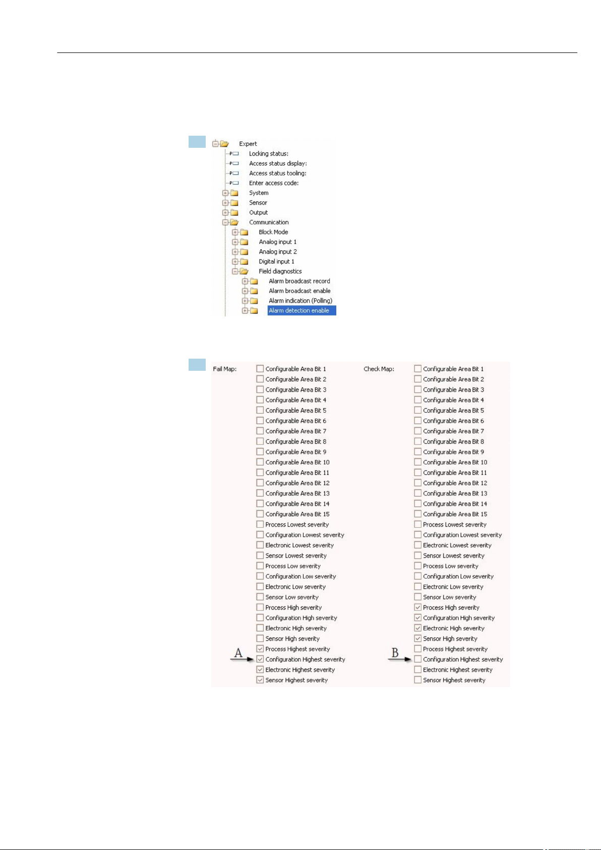
Micropilot FMR51, FMR52 FOUNDATION Fieldbus Commissioning (block-based operation)
Example
The Highest severity / Configuration group contains the messages 410: Data transfer,
411: Up-/Download, 435: Linearization and 437: Configuration incompatible. These
messages are no longer to be classified as Failure (F) but as Funcktion check (C).
1.
Use the FieldCare navigation window to navigate to the the following screen: Expert
→ Communication → Field diagnostics → Alarm detection enable.
2.
22 Default state of the "Fail Map" and "Check Map" columns
Look for the Configuration Highest Severity group in the Fail Map column and
deactivate the associated checkbox (A). Activate the respective checkbox in the
Check Map column (B). Remember to confirm each change by pressing the Enter
key.
Endress+Hauser 91
Page 92

Commissioning (block-based operation) Micropilot FMR51, FMR52 FOUNDATION Fieldbus
23 Changed state of the "Fail Map" and "Check Map" columns
Make sure that for each group the corresponding bit is set to 1 in at least one of the
allocation parameters. Otherwise no event category is transmitted with the event
message. As a consequence the message will not be recognized by the control system.
The Alarm detection enable screen is used to configure the detection of diagnostic
events but not the transmission of event messages to the bus. The latter is configured
on the Alarm broadcast enable screen, which is operated exactly in the same way as
the Alarm detection enable screen. Status information is only transmitted to the bus
if the Resource Block is in the Auto mode.
92 Endress+Hauser
Page 93
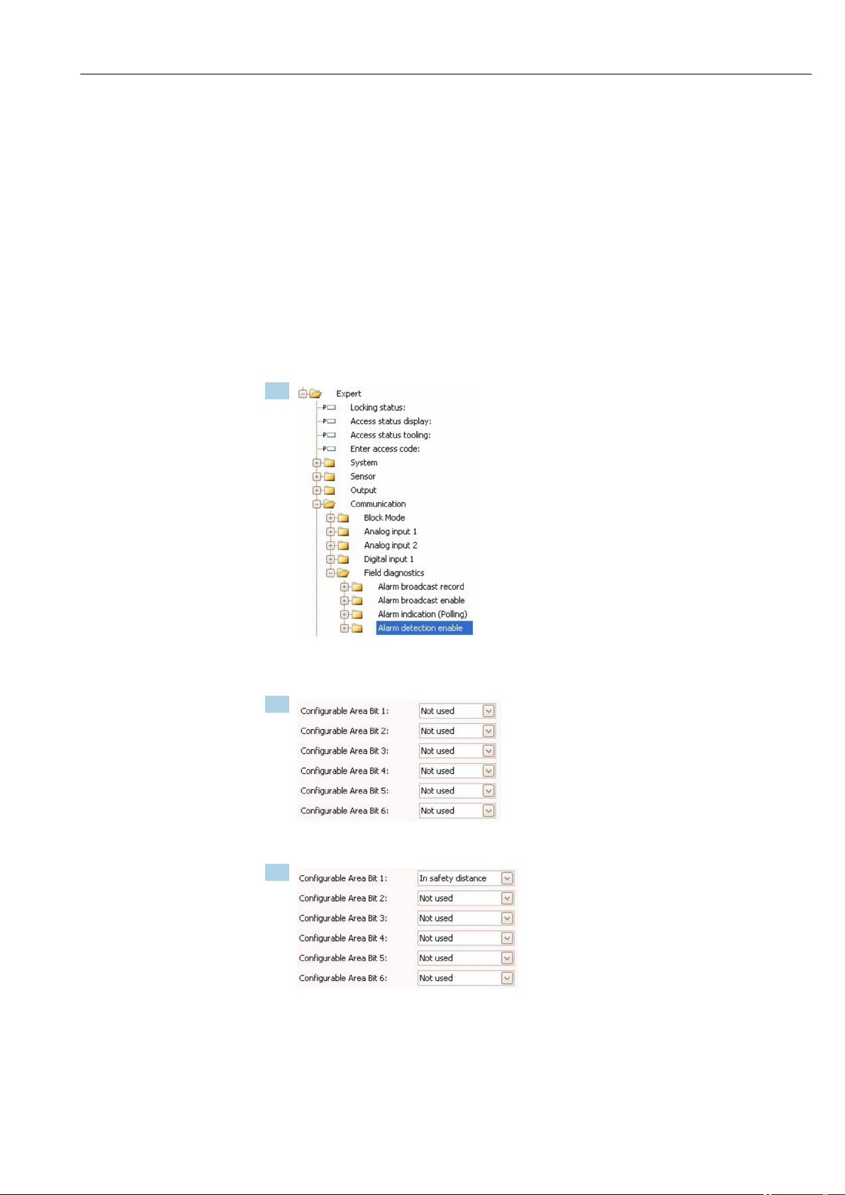
Micropilot FMR51, FMR52 FOUNDATION Fieldbus Commissioning (block-based operation)
12.8.3 Configurable area
An event category can be individually defined for the following parameters - irrespective of
the group of events they belong to by default.
• F941: Echo lost
• S942: In safety distance
• M950: Advanced Diagnostic occurred
Prior to changing the event category, the event must be allocated to one of the bits 1 to 15.
This is performed by the parameters FF912 ConfigArea_1 to FF912ConfigArea_15 in
the DIAGNOSTIC (TRDDIAG) block. Thereafter, the selected bit can be switched from 0 to
1 in the desired allocation parameter.
Example
To change the category of error 942 "In safety distance" from Out of specification (S)
(default), to Function check (C), proceed as follows.
1.
Use the FieldCare navigation window to navigate to the the following screen: Expert
→ Communication → Field diagnostics → Alarm detection enable.
2.
By default all Configurable Area Bits are set to not used.
3.
Select one of these bits (in the example: Configurable Area Bit 1) and select In safety
distance from the associated drop-down menu. Confirm the selection by pressing the
Enter key.
Endress+Hauser 93
Page 94
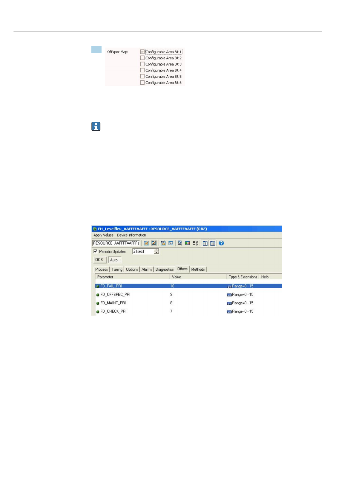
Commissioning (block-based operation) Micropilot FMR51, FMR52 FOUNDATION Fieldbus
4.
Got to the Offspec Map column and activate the checkbox of the respective bit (in
the example: Configurable Area Bit 1). Confirm the selection by pressing the Enter
key.
A change of the error category of In safety distance does not affect an error which is
already present. The new category is only assigned if a new error of this type occurs
after the change.
12.8.4 Transmission of the event meassages to the bus
Event priority
Event messages are only transmitted to the bus if their priority is between 2 and 15.
Events of priority 1 are indicated on the display but not transmitted to the bus. Events of
priority 0 are ignored. By default, the priority is 0 for all events. The priority can be
adjusted individually for each allocation parameter. This is done by the following four
priority parameters:
Suppression of individual events
For individual events, the transmission to the bus can suppressed by the use of a mask.
The corresponding events will be displayed but not transmitted to the bus. In FieldCare,
this mask can be found at Expert → Communication → Field diagnostics → Alarm
broadcast enable. This mask functions as a negative mask, which means that, if a field is
marked, the corresponding events will not be transmitted to the bus.
12.9 Protection of the settings against unauthorized changes
There are two ways to protect the settings against unauthorized changes:
• Via locking switch (hardware locking) → 50
• Via operating menu (software locking) → 48
• Via block operation:
– Block: DISPLAY (TRDDISP); parameter: Define access code (define_access_code)
– Block: EXPERT_CONFIG (TRDEXP); parameter: Enter access code
(enter_access_code)
94 Endress+Hauser
Page 95

Micropilot FMR51, FMR52 FOUNDATION Fieldbus Diagnostics and troubleshooting
13 Diagnostics and troubleshooting
13.1 General trouble shooting
13.1.1 General errors
Error Possible cause Remedial action
Device does not respond. Supply voltage not connected. Connect the correct voltage.
The cables do not contact the
terminals properly.
Values on the display
invisible
"Communication error" is
indicated on the display when
starting the device or
connecting the display
CDI communication does not
work.
Device measures incorrectly. Parametrization error Check and adjust parameterization.
Contrast setting is too weak or too
strong.
The plug of the display cable is not
connected correctly.
Display is defective. Replace display.
Electromagnetic interference Check grounding of the device.
Broken display cable or display plug. Exchange display.
Wrong setting of the COM port on
the computer.
Ensure electrical contact between the
cable and the terminal.
• Increase contrast by pressing and
simultaneously.
• Decrease contrast by pressing and
simultaneously.
Connect the plut correctly.
Check the setting of the COM port on
the computer and change it if necessary.
13.1.2 Parametrization errors
Error Possible cause Remdy
Measured value incorrect If measured distance (Setup
→ Distance) matches the real
distance:
Calibration error
For measurements in bypasses /
stilling well:
• Wrong tank type
• Wrong tube diameter
Enter correct diamter in Enter correct value in Level correction
If measured distance (Setup
→ Distance) does not match the real
distance:
Interference echo
No change of measured value
on filling / emptying
Interference echo from installations,
nozzle or build-up on the antenna.
• Check and adjust
Empty calibration parameter
(→ 127) if necessary.
• Check and adjust Full calibration
parameter (→ 128) if necessary.
• Check and adjust linearization if
necessary (Linearization submenu
(→ 144)).
• Select Tank type (→ 126) =
Bypass / pipe.
• Enter correct diamter in Tube
diameter parameter (→ 127).
parameter (→ 141).
Carry out tank mapping (Confirm
distance parameter (→ 130)).
• Carry out tank mapping (Confirm
distance parameter (→ 130)).
• If necessary, clean antenna
• If necessary, selet better mopunting
position
Endress+Hauser 95
Page 96

Diagnostics and troubleshooting Micropilot FMR51, FMR52 FOUNDATION Fieldbus
Error Possible cause Remdy
If the surface is not calm (e.g.
filling, emptying, agitator
running), the measured value
jumps sporadically to a
higher level
During filling/emptying the
measxured value jumps
downwards
Error message F941 or S941
"Echo lost"
Device displays a level when
the tank is empty.
Wrong slope of the level in
the entire measuring range
Signal is weakened by the rough
surface - the interference echoes are
sometimes stronger.
Multiple echoes • Check Tank type parameter
Level echo is too weak. • Check Medium group parameter
Level echo suppressed. Delete mapping and record it again.
Interference echo Carry out mapping over entire
Wrong tank type selected. Set Tank type parameter (→ 126)
• Carry out tank mapping (Confirm
distance parameter (→ 130)).
• Select Tank type (→ 126) =
Process vessel with agitator.
• Increase integration time (Expert
→ Sensor → Distance → Integration
time)
• Optimize orientation of the antenna
• If necessary, select a better mounting
position and/or larger antenna.
(→ 126).
• If possible, do not select central
installation position.
• If appropriate, use a stilling well.
(→ 127).
• If necessary, select a more detailed
setting in Medium property
parameter (→ 138).
• Optimize alignment of antenna
• If necessary, select a better
installation position and/or larger
antenna.
measuring range when the tank is
empty (Confirm distance parameter
(→ 130)).
correctly.
96 Endress+Hauser
Page 97
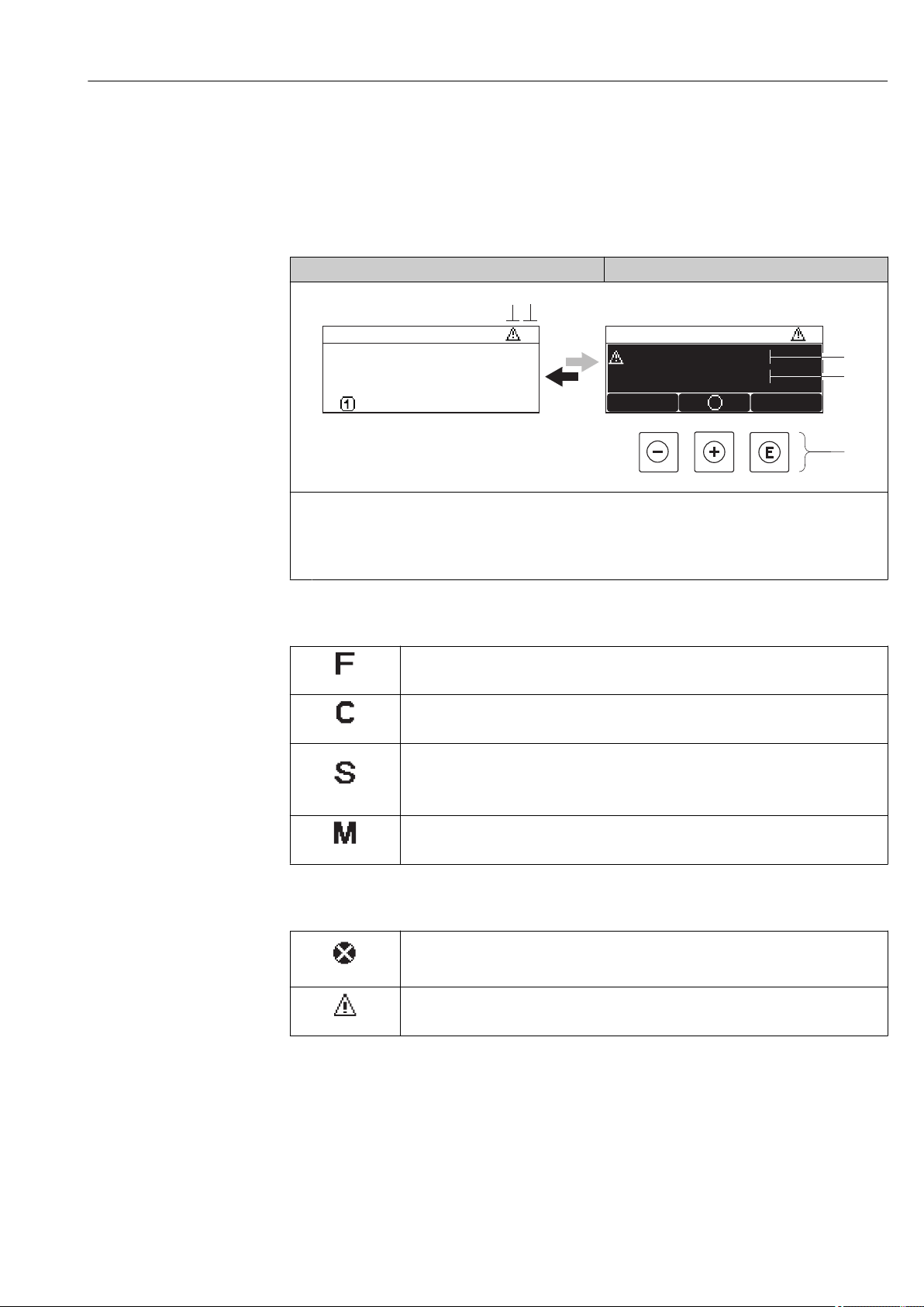
Micropilot FMR51, FMR52 FOUNDATION Fieldbus Diagnostics and troubleshooting
1
4
3
X X X X X X XX X X X X X XX XX X
2
S
S
XX
20.50
5
X
i
S801
Menu
Supply voltage
13.2 Diagnostic information on local display
13.2.1 Diagnostic message
Faults detected by the self-monitoring system of the measuring device are displayed as a
diagnostic message in alternation with the measured value display.
Measured value display in alarm condition Diagnostic message
A0013939-EN
1
Status signal
2
Status symbol (symbol for event level)
3
Status symbol with diagnostics event
4
Event text
5
Operating elements
Status signals
"Failure"
A device error is present. The measured value is no longer valid.
A0013956
"Function check"
The device is in service mode (e.g. during a simulation).
A0013959
"Out of specification"
The device is operated:
• Outside of its technical specifications (e.g. during startup or a cleaning)
A0013958
• Outside of the configuration carried out by the user (e.g. level outside configured span)
"Maintenance required"
Maintenance is required. The measured value is still valid.
A0013957
Status symbol (symbol for event level)
"Alarm" status
The measurement is interrupted. The signal outputs take on the defined alarm condition.
A0013961
A diagnostic message is generated.
"Warning" status
The device continues to measure. A diagnostic message is generated.
A0013962
Endress+Hauser 97
Page 98
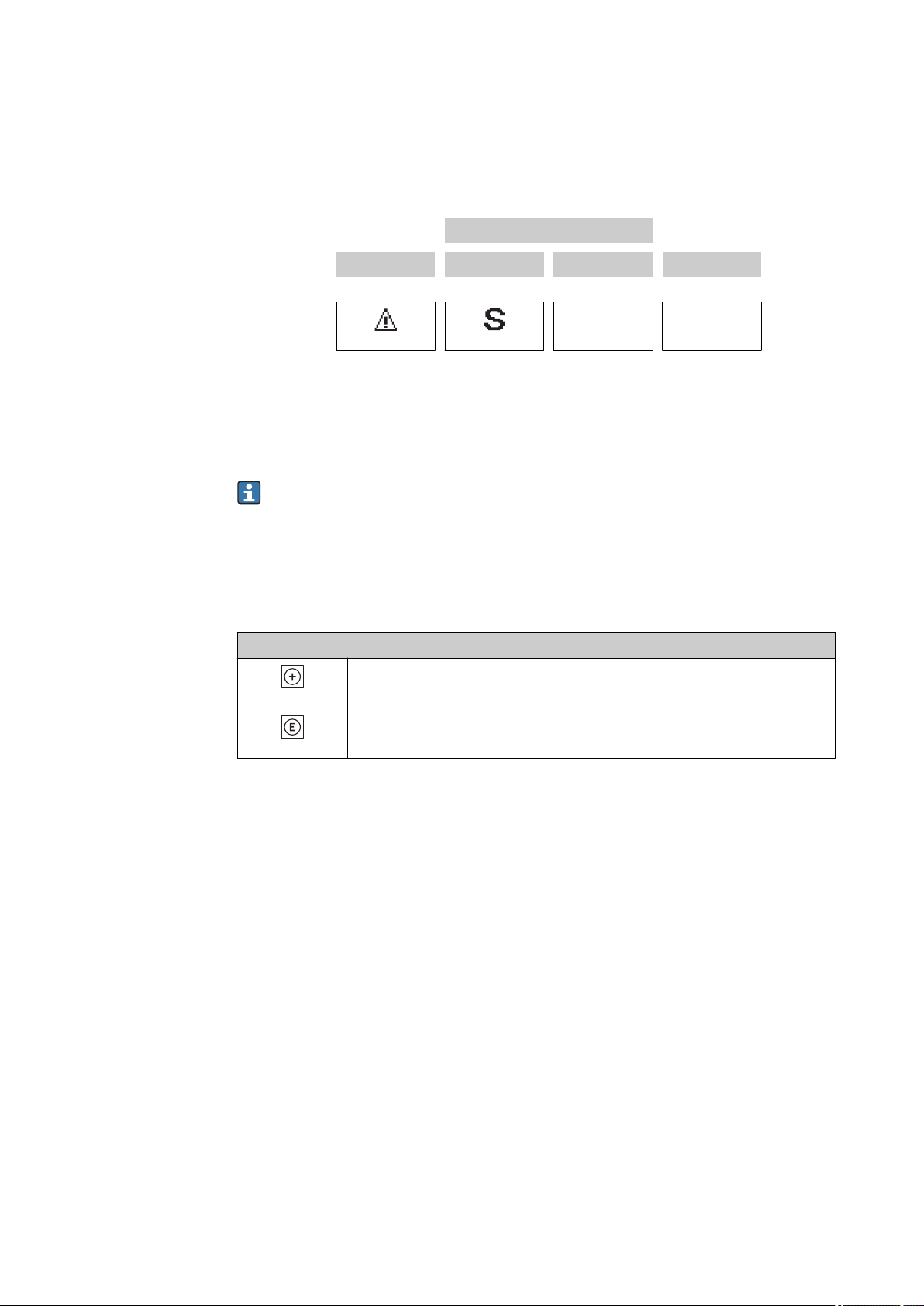
Diagnostics and troubleshooting Micropilot FMR51, FMR52 FOUNDATION Fieldbus
Diagnostics event and event text
The fault can be identified using the diagnostics event. The event text helps you by
providing information about the fault. In addition, the corresponding symbol is displayed
before the diagnostics event.
Diagnostics event
Status symbol Status signal Event number Event text
↓ ↓ ↓
Example
A0013962 A0013958
441 Curr.output 1
3-digit number
If two or more diagnostic messages are pending simultaneously, only the message with the
highest priority is shown. Additional pending diagnostic messages can be shown in
Diagnostic list submenu (→ 176).
Past diagnostic messages that are no longer pending are shown as follows:
• On the local display:
in Event logbook submenu (→ 177)
• In FieldCare:
via the "Event List /HistoROM" function.
Operating elements
Operating functions in menu, submenu
Plus key
Opens the message about the remedial measures.
A0013970
Enter key
Opens the operating menu.
A0013952
98 Endress+Hauser
Page 99
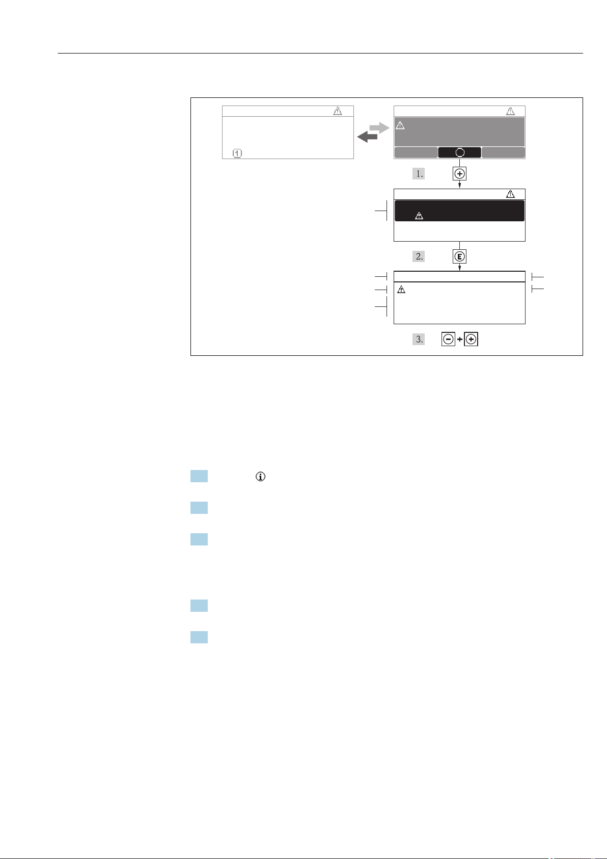
Micropilot FMR51, FMR52 FOUNDATION Fieldbus Diagnostics and troubleshooting
X X XX X X XX X XX X X X XXX X
S
S
XX
20.50
X
i
S801
Menu
S
(ID:203)
S801 0d00h02m25s
1
2
4
6
3
5
Increase supply voltage
S801 Supply voltage
Diagnostic list
Diagnostics 1
Diagnostics 2
Diagnostics 3
Supply voltage
Supply voltage
13.2.2 Calling up remedial measures
24 Message for remedial measures
1 Diagnostic information
2 Short text
3 Service ID
4 Diagnostic behavior with diagnostic code
5 Operation time of occurrence
6 Remedial measures
The user is in the diagnostic message.
1. Press ( symbol).
Diagnostic list submenu opens.
2. Select the desired diagnostic event with or and press .
The message for the remedial measures for the selected diagnostic event opens.
3. Press + simultaneously.
The message for the remedial measures closes.
The user is in the Diagnostics menu at an entry for a diagnostics event, e.g. in Diagnostic
list submenu or in Previous diagnostics.
1. Press .
The message for the remedial measures for the selected diagnostic event opens.
2. Press + simultaneously.
The message for the remedial measures closes.
A0013940-EN
Endress+Hauser 99
Page 100

Diagnostics and troubleshooting Micropilot FMR51, FMR52 FOUNDATION Fieldbus
13.3 Diagnostic event in the operating tool
If a diagnostic event is present in the device, the status signal appears in the top left status
in the operating tool along with the corresponding symbol for event level in accordance
with NAMUR NE 107:
• Failure (F)
• Function check (C)
• Out of specification (S)
• Maintenance required (M)
Calling up remedial measures
1. Navigate to the Diagnostics menu.
In the Actual diagnostics parameter, the diagnostic event is shown with event
text.
2. On the right in the display range, hover the cursor over the Actual diagnostics
parameter.
A tool tip with remedial measures for the diagnostic event appears.
13.4 Diagnostic messages in the DIAGNOSTIC Transducer Block (TRDDIAG)
• The Actual diagnostics parameter displays the message with the highest priority. Every
message is also output as per the FOUNDATION Fieldbus Specification by means of the
XD_ERROR and BLOCK_ERROR parameters.
• A list of diagnostic messages is displayed in the Diagnostics 1 to Diagnostics 5
parameters. If more than 5 messages are currently active, only those with the highest
priority are displayed.
• You can view a list of alarms which are no longer active (event log) via the Previous
diagnostics parameter.
13.5 Diagnostic list
In the Diagnostic list submenu, up to 5 currently pending diagnostic messages can be
displayed. If more than 5 messages are pending, the messages with the highest priority are
shown on the display.
Navigation path
Diagnostics → Diagnostic list
Calling up and closing the remedial measures
1. Press .
The message for the remedial measures for the selected diagnostic event opens.
2. Press + simultaneously.
The message about the remedial measures closes.
100 Endress+Hauser
 Loading...