

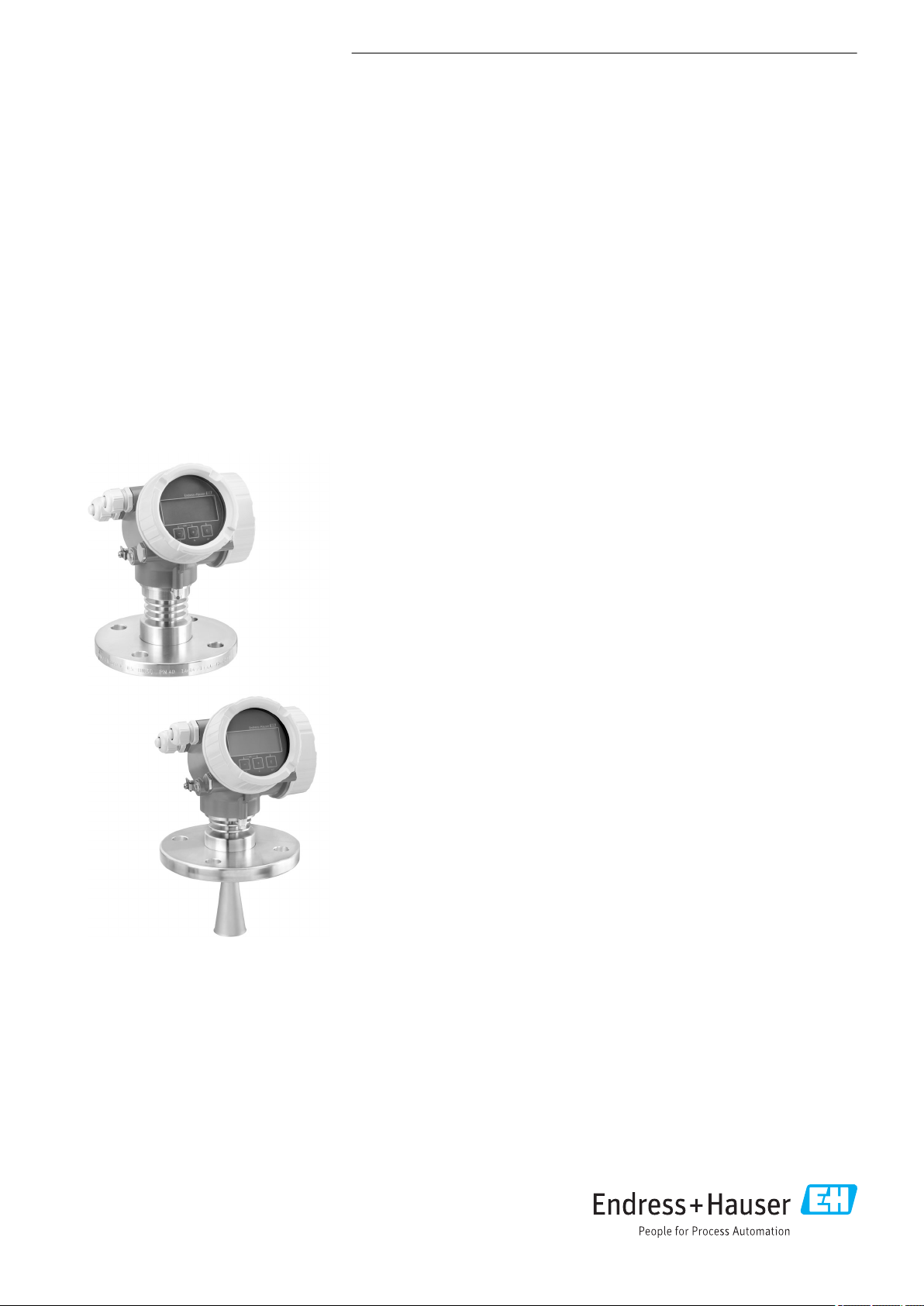
Endress+Hauser Micropilot FMR51, Micropilot FMR52, Micropilot FMR53, Micropilot FMR54 Technical Information
Page 1
TI01040F/00/EN/08.17
71375707
Products
Solutions Services
Technical Information
Micropilot FMR51, FMR52
Free space radar
Level measurement in liquids
Application
• Continuous, non-contact level measurement of liquids, pastes and slurries
• Horn antenna (FMR51); flush mounted, completely filled PTFE horn antenna
(FMR52)
• Maximum measuring range: 70 m (230 ft)
• Temperature: –196 to +450 °C (–321 to +842 °F)
• Pressure: –1 to +160 bar (–14.5 to +2 320 psi)
• Accuracy: ± 2 mm
• International explosion protection certificates; WHG; marine approvals
• Linearity protocol (3-point, 5-point)
Your benefits
• Reliable measurement even for changing product and process conditions
• HistoROM data management for easy commissioning, maintenance and
diagnostics
• Highest reliability due to Multi-Echo Tracking
• SIL2 according to IEC 61508, SIL3 in case of homogeneous or heterogeneous
redundancy
• Seamless integration into control or asset management systems
• Intuitive user interface in national languages
• Easy proof test for SIL and WHG
• Heartbeat Technology™
Page 2

Table of contents
Micropilot FMR51, FMR52
Important document information ............... 4
Symbols .................................... 4
Function and system design ................... 6
Measuring principle ............................ 6
Input ..................................... 8
Measured variable ............................. 8
Measuring range .............................. 8
Operating frequency .......................... 13
Transmitting power ........................... 13
Output .................................. 14
Output signal ............................... 14
Signal on alarm .............................. 15
Linearization ............................... 15
Galvanic isolation ............................ 15
Protocol-specific data .......................... 15
Power supply ............................. 20
Terminal assignment .......................... 20
Device plug connectors ......................... 27
Supply voltage .............................. 28
Power consumption ........................... 30
Current consumption .......................... 30
Power supply failure .......................... 31
Potential equalization ......................... 31
Terminals ................................. 31
Cable entries ............................... 31
Cable specification ............................ 31
Overvoltage protection ......................... 32
Performance characteristics .................. 33
Reference operating conditions ................... 33
Maximum measured error ....................... 33
Measured value resolution ...................... 34
Reaction time ............................... 34
Influence of ambient temperature ................. 34
Influence of gas layer .......................... 34
Gas phase compensation with external pressure sensor
(PROFIBUS PA, FOUNDATION Fieldbus) ............. 35
Installation ............................... 36
Installation conditions ......................... 36
Measuring conditions .......................... 40
Mounting cladded flanges ....................... 41
Installation in vessel (free space) .................. 41
Installation in stilling well ....................... 45
Installation in bypass .......................... 47
Vessels with heat insulation ..................... 49
Environment .............................. 50
Ambient temperature range ..................... 50
Ambient temperature limits ..................... 50
Storage temperature .......................... 58
Climate class ............................... 58
Altitude according to IEC61010-1 Ed.3 .............. 58
Degree of protection .......................... 58
Vibration resistance ........................... 58
Cleaning the antenna .......................... 58
Electromagnetic compatibility (EMC) ............... 59
Process .................................. 60
Process temperature, Process pressure .............. 60
Dielectric constant ............................ 62
Mechanical construction .................... 63
Dimensions ................................ 63
Weight ................................... 73
Materials: GT18 housing (stainless steel, corrosion-
resistant) .................................. 74
Materials: GT19 housing (plastic) .................. 75
Materials: GT20 housing (die-cast aluminum, powder-
coated) ................................... 76
Materials: Antenna and process connection ........... 77
Materials: Weather protection cover ................ 79
Operability ............................... 80
Operating concept ............................ 80
Local operation .............................. 81
Operation with remote display and operating module
FHX50 ................................... 81
Remote operation ............................ 82
Integration in tank gauging system ................. 85
SupplyCare inventory management software .......... 86
Certificates and approvals ................... 89
CE mark ................................... 89
RoHS ..................................... 89
RCM-Tick marking ............................ 89
Ex approval ................................ 89
Dual seal according to ANSI/ISA 12.27.01 ............ 89
Functional Safety ............................ 89
WHG ..................................... 89
Sanitary compatibility ......................... 89
NACE MR 0175 / ISO 15156 ..................... 90
NACE MR 0103 ............................. 90
Pressure equipment with allowable pressure
≤ 200 bar (2 900 psi) .......................... 90
Marine certificate ............................ 90
Radio standard EN302729-1/2 ................... 90
Radio standard EN302372-1/2 ................... 91
FCC / Industry Canada ......................... 91
Japanese radio approval ........................ 92
CRN approval ............................... 92
Track record ................................ 93
Test, Certificate .............................. 94
Product documentation on paper .................. 94
Other standards and guidelines ................... 95
Ordering information ....................... 96
Ordering information .......................... 96
3-point linearity protocol ....................... 97
5-point linearity protocol ....................... 98
Customized parametrization ..................... 99
2 Endress+Hauser
Page 3

Micropilot FMR51, FMR52
Tagging (TAG) .............................. 99
Services ................................... 99
Application Packages ...................... 100
Heartbeat Diagnostics ........................ 100
Heartbeat Verification ........................ 101
Heartbeat Monitoring ......................... 102
Accessories .............................. 103
Device-specific accessories ...................... 103
Communication-specific accessories ............... 108
Service-specific accessories ..................... 109
System components .......................... 109
Documentation ........................... 110
Standard documentation ....................... 110
Supplementary documentation ................... 110
Safety Instructions (XA) ....................... 110
Registered trademarks ..................... 113
Patents ................................. 113
Endress+Hauser 3
Page 4
Important document information
DANGER
WARNING
CAUTION
NOTICE
A
Symbols Safety symbols
Symbol Meaning
Electrical symbols
Micropilot FMR51, FMR52
DANGER!
This symbol alerts you to a dangerous situation. Failure to avoid this situation will
result in serious or fatal injury.
WARNING!
This symbol alerts you to a dangerous situation. Failure to avoid this situation can
result in serious or fatal injury.
CAUTION!
This symbol alerts you to a dangerous situation. Failure to avoid this situation can
result in minor or medium injury.
NOTE!
This symbol contains information on procedures and other facts which do not result in
personal injury.
Symbol Meaning
Direct current
Alternating current
Direct current and alternating current
Ground connection
A grounded terminal which, as far as the operator is concerned, is grounded via a
grounding system.
Protective Earth (PE)
A terminal which must be connected to ground prior to establishing any other
connections.
The ground terminals are situated inside and outside the device:
• Inner ground terminal: Connects the protectiv earth to the mains supply.
• Outer ground terminal: Connects the device to the plant grounding system.
Symbols for certain types of information
Symbol Meaning
Permitted
Procedures, processes or actions that are permitted.
Preferred
Procedures, processes or actions that are preferred.
Forbidden
Procedures, processes or actions that are forbidden.
Tip
Indicates additional information.
Reference to documentation.
Reference to page.
Reference to graphic.
Visual inspection.
4 Endress+Hauser
Page 5
Micropilot FMR51, FMR52
1.
-
.
Symbols in graphics
Symbol Meaning
1, 2, 3 ... Item numbers
, 2., 3.… Series of steps
A, B, C, ... Views
A-A, B-B, C-C, ... Sections
Hazardous area
Indicates a hazardous area.
Safe area (non-hazardous area)
Indicates the non-hazardous area.
Symbols at the device
Symbol Meaning
Safety instructions
Observe the safety instructions contained in the associated Operating Instructions.
Temperature resistance of the connection cables
Specifies the minimum value of the temperature resistance of the connection cables.
Endress+Hauser 5
Page 6

Function and system design
F
L
D
E
R
0%
100%
Micropilot FMR51, FMR52
Measuring principle
The Micropilot is a "downward-looking" measuring system, operating based on the time-of-flight
method (ToF). It measures the distance from the reference point (process connection) to the product
surface. Radar impulses are emitted by an antenna, reflected off the product surface and received
again by the radar system.
A0017871
1 Setup parameters of the Micropilot
R Reference point of the measurement (lower edge of the flange or threaded connection)
E Empty calibration ( = zero)
F Full calibration (= span)
D Measured distance
L Level (L = E - D)
Input
The reflected radar impulses are received by the antenna and transmitted into the electronics. A
microprocessor evaluates the signal and identifies the level echo caused by the reflection of the radar
impulse at the product surface. The unambiguous signal identification is accomplished by the
PulseMaster® eXact software together with the Multi-echo tracking algorithms, based on many
years of experience with time-of-flight technology.
The distance D to the product surface is proportional to the time of flight t of the impulse:
D = c · t/2,
with c being the speed of light.
Based on the known empty distance E, the level L is calculated:
L = E – D
The reference point R of the measurement is located at the process connection. For details see the
dimensional drawing:
• FMR51: → 64
• FMR52: → 70
The Micropilot is equipped with functions to suppress interference echoes. The user can activate
these functions. Together with the multi-echo tracking algorithms they ensure that interference
echoes (i.e. from edges and weld seams) are not interpreted as level echo.
6 Endress+Hauser
Page 7

Micropilot FMR51, FMR52
Output
The Micropilot is commissioned by entering an empty distance "E" (=zero), a full distance "F" (=span)
and application parameters which automatically adapt the instrument to the process conditions. For
models with a current output, the factory adjustment for zero point "E" and span "F" is 4 mA and 20
mA. For digital outputs and the display module, the factory adjustment for zero point "E" and span "F"
is 0 % and 100 %.
A linearization with max. 32 points, based on a table entered either manually or semi-automatically,
can be activated locally or remotely. This function provides a measurement in engineering units and
a linear output signal for spheres, horizontal cylindrical tanks and vessels with conical outlet.
Life cycle of the product
Engineering
• Universal measuring principle
• Measurement unaffected by medium properties
• Hardware and software developed according to SIL IEC 61508
Procurement
• Endress+Hauser being the world market leader in level measurement guarantees asset protection
• Worldwide support and service
Installation
• Special tools are not required
• Reverse polarity protection
• Modern, detachable terminals
• Main electronics protected by a separate connection compartment
Commissioning
• Fast, menu-guided commissioning in only a few steps on site or from the control room
• Plain text display in national languages reduces the risk of error or confusion
• Direct local access of all parameters
• Short instruction manual at the device
Operation
• Multi-echo tracking: Reliable measurement through self-learning echo-search algorithms taking
into account the short-term and long-term history in order to check the found echoes for
plausibility and to suppress interference echoes.
• Diagnostics in accordance with NAMUR NE107
Maintenance
• HistoROM: Data backup for instrument settings and measured values
• Exact instrument and process diagnosis to assist fast decisions with clear details concerning
remedies
• Intuitive, menu-guided operating concept in national languages saves costs for training,
maintenance and operation
• Cover of the electronics compartment can be opened in hazardous areas
Retirement
• Order code translation for subsequent models
• RoHS-conforming (Restriction of certain Hazardous Substances), unleaded soldering of electronic
components
• Environmentally sound recycling concept
Endress+Hauser 7
Page 8
Input
Micropilot FMR51, FMR52
Measured variable
The measured variable is the distance between the reference point and the product surface.
The level is calculated from this distance, taking into account the empty distance "E" entered by the
user.
If required, the level can be converted into other variables (volume, mass) by means of a linearization
(up to 32 points).
Measuring range Maximum measuring range
Device Maximum measuring range
FMR51 - standard version 40 m (131 ft)
FMR51 - with "Advanced dynamics" application package 70 m (230 ft)
FMR52 - standard version 40 m (131 ft)
FMR52 - with "Advanced dynamics" application package 60 m (197 ft)
Usable measuring range
The usable measuring range depends on the size of the antenna, the reflectivity of the medium, the
mounting location and eventual interference reflections.
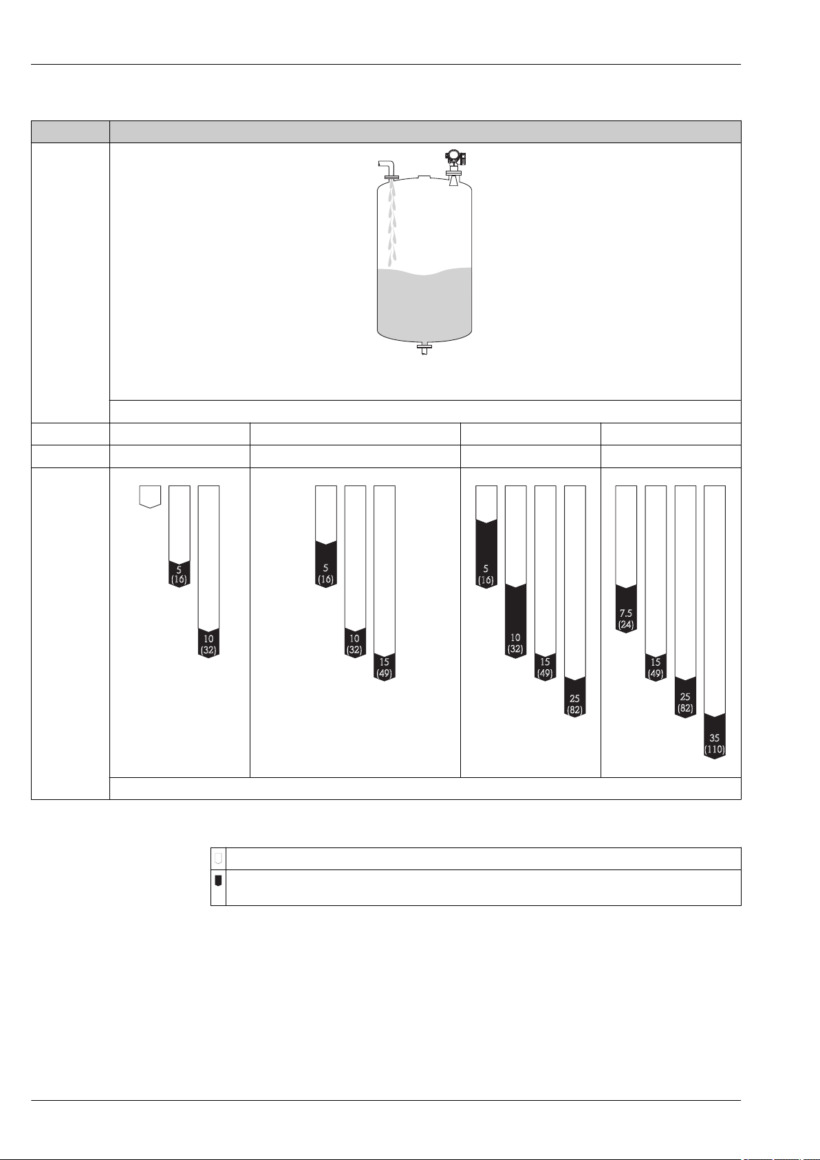
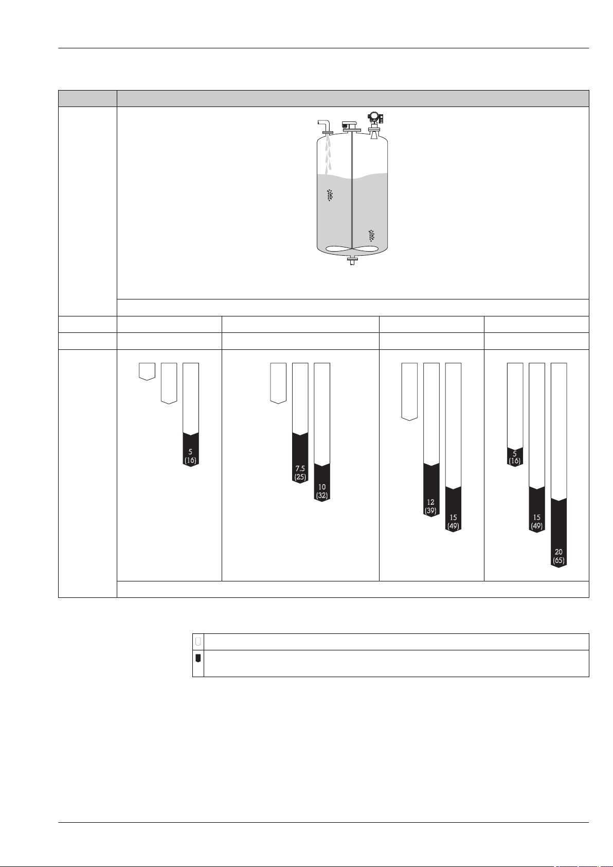
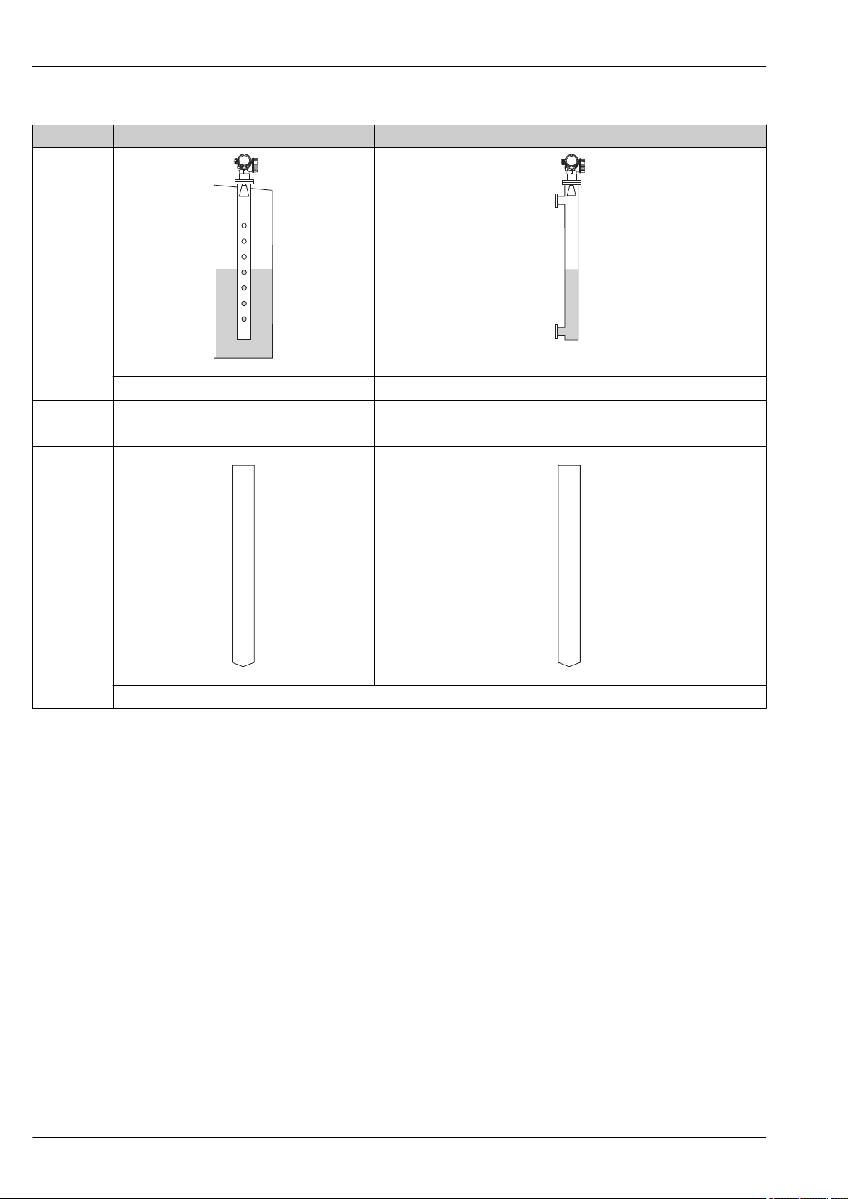
The following tables describe the groups of media as well as the achievable measuring range as a
function of application and media group. If the dielectric constant of a medium is unknown, it is
recommended to assume media group B to ensure a reliable measurement.
Media groups
Media groups DC (εr) Example
A 1.4 to 1.9 non-conducting liquids, e.g. liquefied gas
B 1.9 to 4 non-conducting liquids, e.g. benzene, oil, toluene, …
C 4 to 10 e.g. concentrated acids, organic solvents, esters, aniline, alcohol, acetone, …
D > 10 conducting liquids, e.g. aqueous solutions, dilute acids and alkalis
1) Treat Ammonia NH3 as a medium of group A.
1)
For dielectric constants (DC values) of many media commonly used in various industries refer
to:
• the Endress+Hauser DC manual (CP01076F)
• the Endress+Hauser "DC Values App" (available for Android and iOS)
8 Endress+Hauser
Page 9
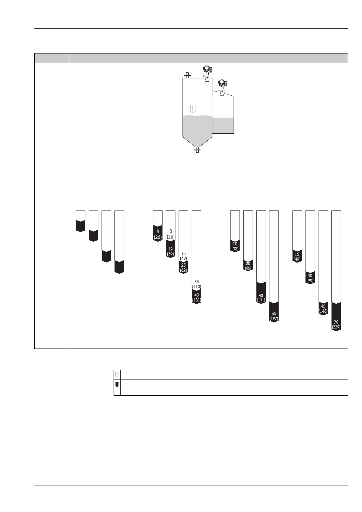
Micropilot FMR51, FMR52
A B
25
(82)
15
(49)
C D
3
(9.9)
10
(32)
15
(49)
5
(16)
8
(26)
5
(16)
A B C D
4
(13)
8
(26)
8
(26)
15
(49)
12
(39)
25
(82)
35
(110)
40
(131)
A B C D
8
(26)
15
(49)
30
(98)
40
(131)
10
(32)
20
(65)
40
(131)
60
(197)
A B C D
10
(32)
25
(82)
40
(131)
40
(131)
15
(49)
30
(99)
45
(148)
70
(229)
Device Storage tank
Calm product surface (e.g. intermittent filling, filling from bottom, immersion tubes)
Antenna size
FMR51 40 mm (1½ in) 50 mm (2 in) 80 mm (3 in) 100 mm (4 in)
FMR52 - 50 mm (2 in) 80 mm (3 in) -
A0018833
Endress+Hauser 9
A0018858
A0018859
A0018860
A0018862
Measuring range [m (ft)]
Legend
Measuring range of the standard version
Measuring range for the "Advanced dynamics" application package (product structure: feature 540:
"Application Package", Option EM: "Advanced dynamics")
Page 10
Micropilot FMR51, FMR52
B C D
(6.6)
4
(13)
7.5
(24)
10
(32)
(16)
5
2
BB CC DD
3
(9.9)
7.5
(24)
10
(32)
5
(16)
10
(32)
15
(49)
A B C D
2.5
(8)
5
(16)
10
(32)
15
(49)
5
(16)
10
(32)
15
(49)
25
(82)
A B C D
5
(16)
10
(32)
15
(49)
25
(82)
7.5
(24)
15
(49)
25
(82)
35
(110)
Device Buffer tank
Moving surfaces (e.g. continuous filling, from above, mixing jets)
Antenna size
FMR51 40 mm (1½ in) 50 mm (2 in) 80 mm (3 in) 100 mm (4 in)
FMR52 - 50 mm (2 in) 80 mm (3 in) -
A0018835
A0018863
A0018864
A0018865
Measuring range [m (ft)]
Legend
Measuring range of the standard version
Measuring range for the "Advanced dynamics" application package (product structure: feature 540:
"Application Package", Option EM: "Advanced dynamics")
10 Endress+Hauser
A0018866
Page 11
Micropilot FMR51, FMR52
B C D
1
(3.2)
2
(6.6)
3
(9.8)
5
(16)
B C D
2
(6.6)
3
(9.8)
5
(16)
7.5
(25)
10
(32)
B C D
2.5
(8.2)
5
(16)
12
(39)
15
(49)
8
(26)
B C D
4
(13)
(16)
5
8
(26)
15
(49)
20
(65)
10
(32)
Device Process tank with agitator
Turbulent surface (e.g. filling from above, agitators, baffles)
Antenna size
FMR51 40 mm (1½ in) 50 mm (2 in) 80 mm (3 in) 100 mm (4 in)
FMR52 - 50 mm (2 in) 80 mm (3 in) -
A0018837
A0018867
A0018868
A0018869
Measuring range [m (ft)]
Legend
Measuring range of the standard version
Measuring range for the "Advanced dynamics" application package (product structure: feature 540:
"Application Package", Option EM: "Advanced dynamics")
Endress+Hauser 11
A0018870
Page 12
Micropilot FMR51, FMR52
20
(66)
A, B, C, D
20
(66)
C, D
Device Stilling well Bypass
A0018842
Antenna size Antenna size
FMR51 40 ... 100 mm ( 1½ ... 4 in) 40 ... 100 mm ( 1½ ... 4 in)
FMR52 50 ... 80 mm ( 2 ... 3 in) 50 ... 80 mm ( 2 ... 3 in)
A0018840
A0018851
Measuring range [m (ft)]
A0018852
12 Endress+Hauser
Page 13

Micropilot FMR51, FMR52
Operating frequency
Transmitting power
K-band (~ 26 GHz)
Up to 8 Micropilot transmitters can be installed in the same tank because the transmitter pulses are
statistically coded.
Distance Average energy density in beam direction
Standard version With "Advanced dynamics" application
1 m (3.3 ft) < 12 nW/cm
5 m (16 ft) < 0.4 nW/cm
2
2
1) Product structure, feature 540: "Application package", option EM: "Advanced dynamics"
1)
package
< 64 nW/cm
< 2.5 nW/cm
2
2
Endress+Hauser 13
Page 14
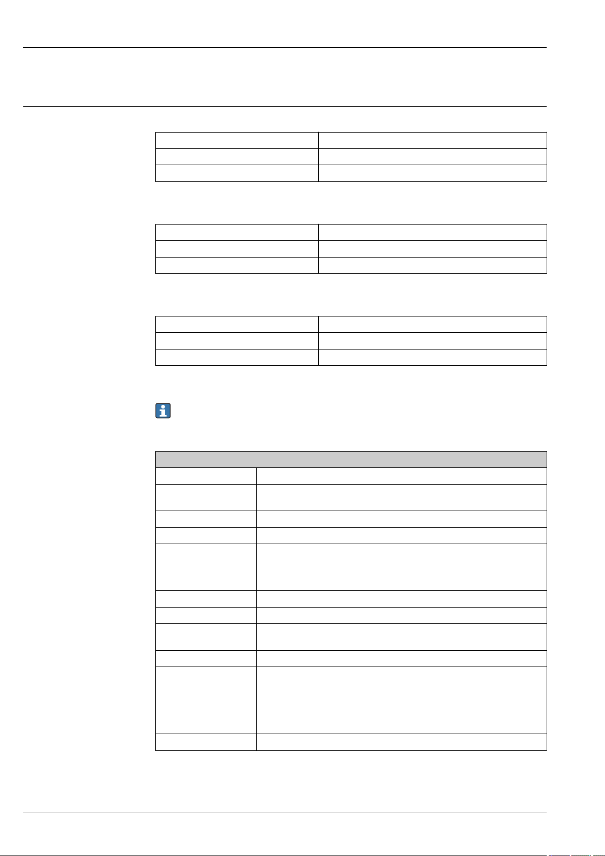
Output
Output signal HART
Signal coding FSK ±0.5 mA over current signal
Data transmission rate 1 200 Bit/s
Galvanic isolation Yes
PROFIBUS PA
Signal coding Manchester Bus Powered (MBP)
Data transmission rate 31.25 kBit/s, voltage mode
Galvanic isolation Yes
FOUNDATION Fieldbus
Signal coding Manchester Bus Powered (MBP)
Data transmission rate 31.25 kBit/s, voltage mode
Galvanic isolation Yes
Micropilot FMR51, FMR52
Switch output
For HART devices, the switch output is available as an option. See product structure, feature 20:
"Power Supply, Output", option B: "2-wire; 4-20mA HART, switch output"
Devices with PROFIBUS PA and FOUNDATION Fieldbus always have a switch output.
Switch output
Function Open collector switching output
Switching behavior Binary (conductive or non-conductive), switches when the programmable switch
point is reached
Failure mode non-conductive
Electrical connection values U = 16 to 35 VDC, I = 0 to 40 mA
Internal resistance RI < 880 Ω
The voltage drop at this internal resistance has to be taken into account on
planning the configuration. For example, the resulting voltage at a connected
relay must be sufficient to switch the relay.
Insulation voltage floating, Insulation voltage 1 350 VDC to power supply aund 500 VAC to ground
Switch point freely programmable, separately for switch-on and switch-off point
Switching delay freely programmable from 0 to 100 s, separately for switch-on and switch-off
point
Number of switching cycles corresponds to the measuring cycle
Signal source
device variables
Number of switching cycles unlimited
• Level linearized
• Distance
• Terminal voltage
• Electronic temperature
• Relative echo amplitude
• Diagnostic values, Advanced diagnostics
14 Endress+Hauser
Page 15

Micropilot FMR51, FMR52
Signal on alarm
Depending on the interface, failure information is displayed as follows:
• Current output (for HART devices)
– Failsafe mode selectable (in accordance with NAMUR Recommendation NE 43):
– Failsafe mode with user-selectable value: 3.59 to 22.5 mA
• Local display
– Status signal (in accordance with NAMUR Recommendation NE 107)
– Plain text display
• Operating tool via digital communication (HART, PROFIBUS PA, FOUNDATION Fieldbus) or
service interface (CDI)
– Status signal (in accordance with NAMUR Recommendation NE 107)
– Plain text display
Linearization
The linearization function of the device allows the conversion of the measured value into any unit of
length or volume. Linearization tables for calculating the volume in cylindrical tanks are preprogrammed. Other linearization tables of up to 32 value pairs can be entered manually or semiautomatically.
Galvanic isolation
All circuits for the outputs are galvanically isolated from each other.
Protocol-specific data HART
Manufacturer ID 17 (0x11)
Device type ID 0x1128
HART specification 7.0
Device description files (DTM, DD) Information and files under:
HART load min. 250 Ω
HART device variables The measured values can be freely assigned to the device variables.
Supported functions • Burst mode
Minimum alarm: 3.6 mA
Maximum alarm (= factory setting): 22 mA
• www.endress.com
• www.fieldcommgroup.org
Measured values for PV (primary variable)
• Level linearized
• Distance
• Electronic temperature
• Relative echo amplitude
• Area of incoupling
• Analog output adv. diagnostics 1
• Analog output adv. diagnostics 2
Measured values for SV, TV, FV (second, third and fourth variable)
• Level linearized
• Distance
• Electronic temperature
• Terminal voltage
• Relative echo amplitude
• Absolute echo amplitude
• Area of incoupling
• Analog output adv. diagnostics 1
• Analog output adv. diagnostics 2
• Additional transmitter status
Wireless HART data
Minimum start-up voltage 16 V
Start-up current 3.6 mA
Start-up time 65 s
Minimum operating voltage 14.0 V
Endress+Hauser 15
Page 16
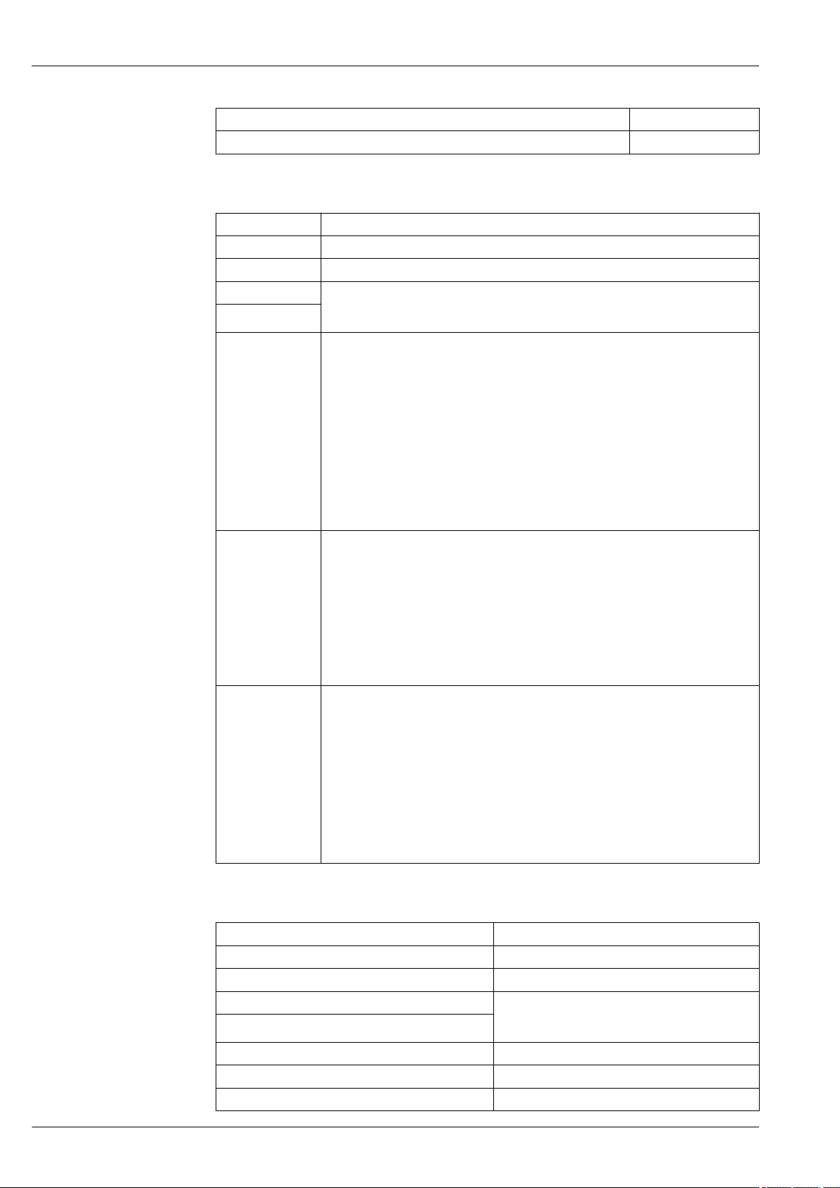
Micropilot FMR51, FMR52
Multidrop current 4.0 mA
Set-up time 15 s
PROFIBUS PA
Manufacturer ID 17 (0x11)
Ident number 0x1559
Profile version 3.02
GSD file Information and files under:
GSD file version
Output values Analog Input:
Input values Analog Output:
Supported functions • Identification & Maintenance
• www.endress.com
• www.profibus.org
• Level linearized
• Distance
• Terminal voltage
• Electronic temperature
• Absolute echo amplitude
• Relative echo amplitude
• Analog output adv. diagnostics 1
• Analog output adv. diagnostics 2
Digital Input:
• Digital output AD 1
• Digital output AD 2
• Switch output
• Analog value from PLC (for sensor block external pressure to compensate gas phase
effects)
• Analog value from PLC to be indicated on the display
Digital Output:
• Extended diagnostic block
• Level limiter
• Sensor block measurement on
• Sensor block save history on
• Status output
Einfachste Geräteidentifizierung seitens des Leitsystems und des Typenschildes
• Automatic Ident Number Adoption
GSD compatibility mode with respect to the preceding product Micropilot M FMR2xx
• Physical Layer Diagnostics
Installation check of the PRFIBUS segment and the Micropilot FMR5x via the terminal
voltage and telegram surveillance.
• PROFIBUS Up-/Download
Up to 10 times faster writing and reading of parameters via PROFIBUS up-/download
• Condensed Status
Simple and self-explanatory diagnostic information by categorization of occurring
diagnostic messages.
FOUNDATION Fieldbus
Manufacturer ID 0x452B48
Device type 0x1028
Device Revision 0x01
DD Revision Information and files can be found:
CFF Revision
Device Tester Version (ITK Version) 6.0.1
ITK Test Campaign Number IT085300
Link Master (LAS) capable yes
• www.endress.com
• www.fieldcommgroup.org
16 Endress+Hauser
Page 17
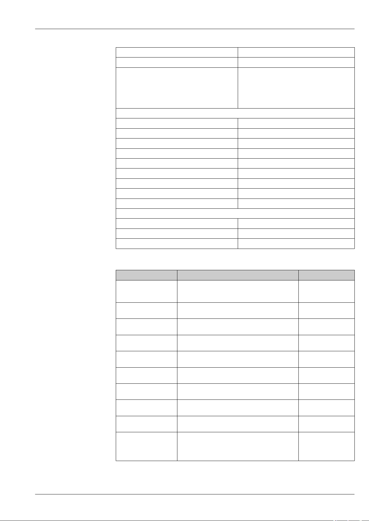
Micropilot FMR51, FMR52
Link Master / Basic Device selectable yes; default: Basic Device
Node address Default: 247 (0xF7)
Features supported Following methods are supported:
• Restart
• ENP Restart
• Setup
• Linearization
• Self Check
Virtual Communication Relationships (VCRs)
Number of VCRs 44
Number of Link Objects in VFD 50
Permanent entries 1
Client VCRs 0
Server VCRs 10
Source VCRs 43
Sink VCRs 0
Subscriber VCRs 43
Publisher VCRs 43
Device Link Capabilities
Slot time 4
Min. inter PDU delay 8
Max. response delay 20
Transducer Blocks
Block Content Output values
Setup Transducer Block Contains all parameters for a standard commissioning
procedure
Advanced Setup
Transducer Block
Display Transducer Block Contains all parameters for the configuration of the
Diagnostic Transducer
Block
Advanced Diagnostic
Transducer Block
Expert Configuration
Transducer Block
Expert Information
Transducer Block
Service Sensor Transducer
Block
Service Information
Transducer Block
Data Transfer Transducer
Block
Contains all parameters for a more detailed
configuration of the device
display module
Contains diagnostic information no output values
Contains parameters for the Advanced Diagnostic no output values
Contains parameters which require detailed knowledge
of the functionalities of the device
Contains information about the state of the device no output values
Contains parameters which can only be operated by
Endress+Hauser service personnel
Contains information on the state of device which is
relevant for service operations
Contains parameters which allow to backup the device
configuration in the display module and to restore it
into the device. Access to these parameters is restricted
to the Endress+Hauser service.
• Level or volume
(Channel 1)
• Distance (Channel 2)
no output values
no output values
no output values
no output values
no output values
no output values
1)
1) depending on the configuration of the block
Endress+Hauser 17
Page 18

Function Blocks
Micropilot FMR51, FMR52
Block Content Number of
permanent
blocks
Resource Block The Resource Block contains all the
data that uniquely identifies the
field device. It is an electronic
version of a nameplate of the
device.
Analog Input
Block
Discrete Input
Block
Mutiple
Analog Output
Block
Mutiple
Discrete
Output Block
PID Block The PID block serves as
Arithmetic
Block
Signal
Characterizer
Block
Input Selector
Block
The AI block takes the
manufacturer's input data, selected
by channel number, and makes it
available to other function blocks at
its output.
The DI block takes a discrete input
value (e.g. indication of an level
limit), and makes it available to
other function blocks at its output.
This block is used to transfer analog
data from the bus into the device
This block is used to transfer
discrete data from the bus to the
device.
proportional-integralderivative
controller and is used almost
universally to do closed-loopcontrol in the field including
cascade and feedforward.
This block is designed to permit
simple use of popular measurement
math functions. The user does not
have to know how to write
equations. The math algorithm is
selected by name, chosen by the
user for the function to be done.
The signal characterizer block has
two sections, each with an output
that is a non-linear function of the
respective input. The non-linear
function is determined by a single
look-up table with 21 arbitrary x-y
pairs.
The input selector block provides
selection of up to four inputs and
generates an output based on the
configured action. This block
normally receives its inputs from AI
blocks. The block performs
maximum, minimum, middle,
average and ‘first good’ signal
selection.
1 0 - enhanced
2 3 25 ms enhanced
1 2 20 ms standard
1 0 20 ms standard
1 0 20 ms standard
1 1 25 ms standard
1 1 25 ms standard
1 1 25 ms standard
1 1 25 ms standard
Number of
instantiable
blocks
Execution
time
Functionality
18 Endress+Hauser
Page 19
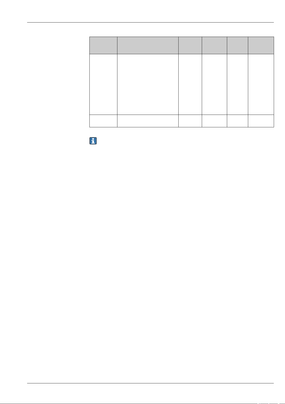
Micropilot FMR51, FMR52
Block Content Number of
permanent
blocks
Integrator
Block
Analog Alarm
Block
The Integrator Function Block
integrates a variable as a function
of the time or accumulates the
counts from a Pulse Input block.
The block may be used as a
totalizer that counts up until reset
or as a batch totalizer that has a
setpoint, where the integrated or
accumulated value is compared to
pre-trip and trip settings,
generating discrete signals when
these settings are reached.
1 1 25 ms standard
1 1 25 ms standard
Number of
instantiable
blocks
Execution
time
Up to 20 blocks can be instantiated in the device altogether, including the blocks already
instantiated on delivery.
Functionality
Endress+Hauser 19
Page 20
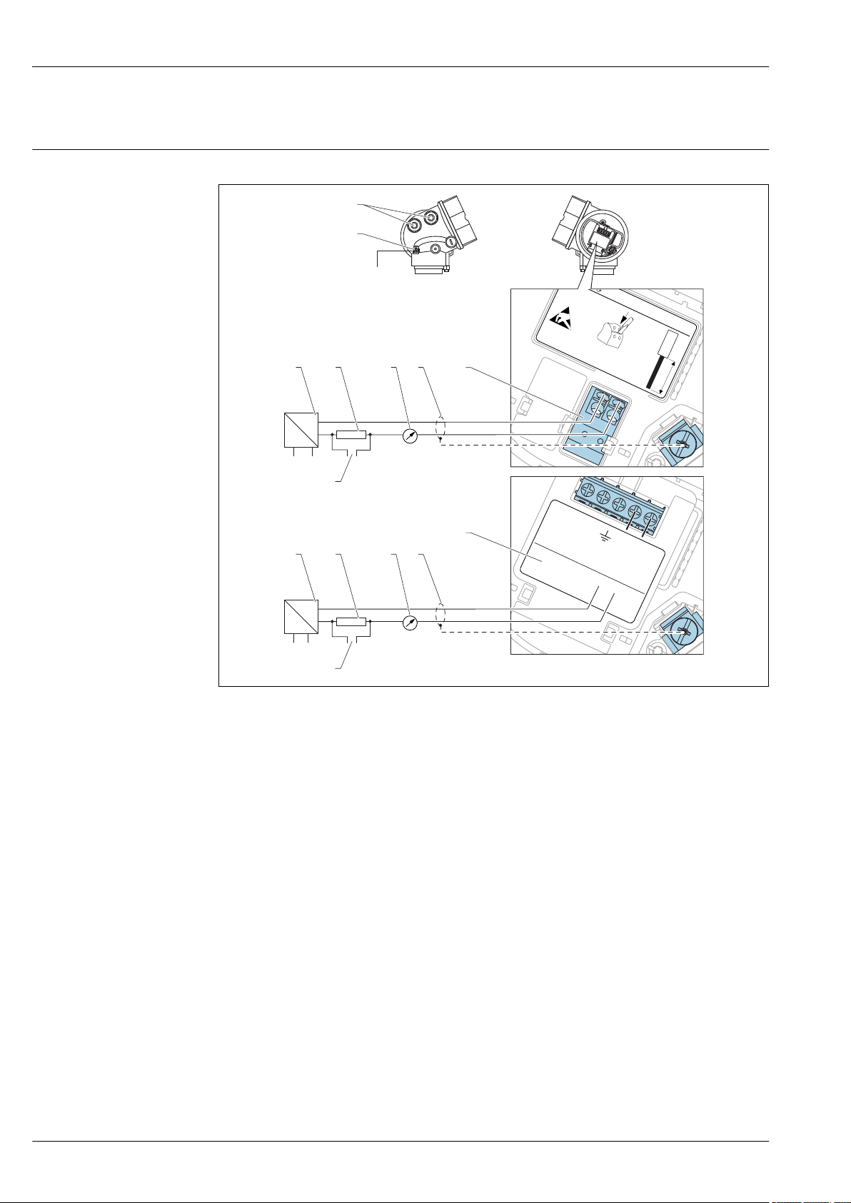
Power supply
8
9
1
+
2
4...20mA
HART
10 mm
Spare part
71108xxx
2- wire level
4-20 mA 4-20 mA
HART
[21]
open
-
1
+
2
4-20mA
1-channel overvoltage protection
-
[16]
A
7
B
!
4...20 mA
5
4
1
2
3
+
–
+
–
#
+
–
4...20 mA
5
4
1
2
3
+
–
6
#
Terminal assignment 2-wire: 4-20mA HART
Micropilot FMR51, FMR52
2 Terminal assignment 2-wire; 4-20mA HART
20 Endress+Hauser
A Without integrated overvoltage protection
B With integrated overvoltage protection
1 Active barrier with power supply (e.g. RN221N): Observe terminal voltage
2 HART communication resistor (≥ 250 Ω): Observe maximum load
3 Connection for Commubox FXA195 or FieldXpert SFX350/SFX370 (via VIATOR Bluetooth modem)
4 Analog display device: Observe maximum load
5 Cable screen; observe cable specification
6 4-20mA HART (passive): Terminals 1 and 2
7 Overvoltage protection module
8 Terminal for potential equalization line
9 Cable entry
A0011294
Page 21
Micropilot FMR51, FMR52
1
+
2
4...20 mA
HART
10 mm
Spare part
71108xxx
2- wire
4-20 mA PFS
HART
[02/03]
open
-
A
1
+
2
-
3
+
4
-
1
3
+
+
2
4
4-20mA/
FIELDBUS
4-20mA/
2-channel overvoltage protection
-
-
[17]
B
10
9
8
7
11
+
+
-
-
2
2
3
3
4
4
6
5
5
1
1
4...20 mA
≥250 Ω
3+
3+
4-
4-
+
+
–
–
$
$
%
4...20 mA
≥250 Ω
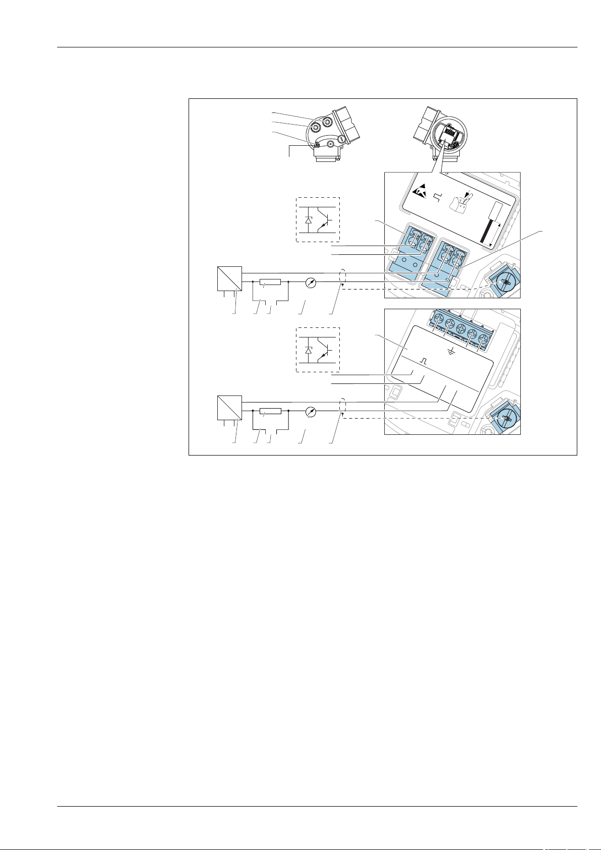
2-wire: 4-20mA HART, switch output
A0013759
3 Terminal assignment 2-wire; 4-20mA HART, switch output
A Without integrated overvoltage protection
B With integrated overvoltage protection
1 Active barrier with power supply (e.g. RN221N): Observe terminal voltage
2 HART communication resistor (≥ 250 Ω): Observe maximum load
3 Connection for Commubox FXA195 or FieldXpert SFX350/SFX370 (via VIATOR Bluetooth modem)
4 Analog display device: Observe maximum load
5 Cable screen; observe cable specification
6 4-20mA HART (passive): Terminals 1 and 2
7 Switch output (open collector): Terminals 3 and 4
8 Terminal for potential equalization line
9 Cable entry for 4-20mA HART line
10 Cable entry for switch output line
11 Overvoltage protection module
Endress+Hauser 21
Page 22
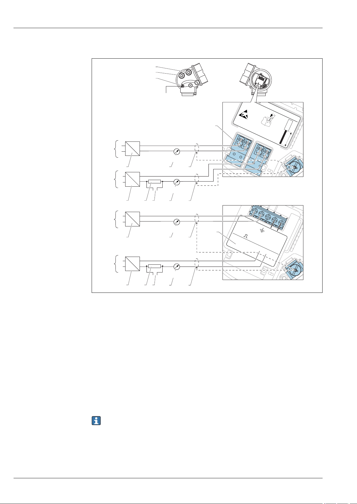
2-wire: 4-20mA HART, 4-20mA
1
3
+
+
2
4
4...20mA
HART
4...20mA
10 mm
Spare part
71108xxx
2- wire level
4-20 mA 4-20 mA
HART
[04/05]
open
-
-
11
A
1
3
+
+
2
4
4-20mA/
FIELDBUS
4-20mA/
2-channel overvoltage protection
-
-
[17]
14
13
12
+
+
+
+
-
-
-
-
1
1
2
2
3
3
9
9
5
5
8
8
6
6
7
7
4
4
4
4
+
+
–
–
+
+
–
–
4...20 mA
4...20 mA
10
B
4...20 mA
4...20 mA
"
"
"
"
#
Micropilot FMR51, FMR52
4 Terminal assignment 2-wire, 4-20 mA HART, 4...20mA
A Without integrated overvoltage protection
B With integrated overvoltage protection
1 Connection current output 2
2 Connection current output 1
3 Supply voltage for current output 1 (e.g. RN221N); Observe terminal voltage
4 Cable screen; observe cable specification
5 HART communication resistor (≥ 250 Ω): Observe maximum load
6 Connection for Commubox FXA195 or FieldXpert SFX350/SFX370 (via VIATOR Bluetooth modem)
7 Analog display device ; observe maximum load
8 Analog display device ; observe maximum load
9 Supply voltage for current output 2 (e.g. RN221N); Obeserve terminal voltage
10 Overvoltage protection module
11 Current output 2: Terminals 3 and 4
12 Terminal for the potential equalization line
13 Cable entry for current output 1
14 Cable entry for current output 2
This version is also suited for single-channel operation. In this case, current output 1 (terminals
1 and 2) must be used.
22 Endress+Hauser
A0013923
Page 23
Micropilot FMR51, FMR52
3
1
+
L+
4
2
4...20 mA
HART
10.4...48 V=
10 mm
Spare part
71108xxx
2- wire
4-20 mA
HART
[08]
open
-
L-
A
13
12
11
9
10
2
3
4
7
8
5
1
!
!
+
-
6
!
4...20 mA
≥250 Ω
4-wire: 4-20mA HART (10.4 to 48 VDC)
A0011340
5 Terminal assignment 4-wire; 4-20mA HART (10.4 to 48 VDC)
1 Evaluation unit, e.g. PLC
2 HART communication resistor (≥ 250 Ω): Observe maximum load
3 Connection for Commubox FXA195 or FieldXpert SFX350/SFX370 (via VIATOR Bluetooth modem)
4 Analog display device: Observe maximum load
5 Signal cable including screening (if required), observe cable specification
6 Protective connection; do not disconnect!
7 Protective earth, observe cable specification
8 4...20mA HART (active): Terminals 3 and 4
9 Supply voltage: Terminals 1 and 2
10 Supply voltage: Observe terminal voltage, observe cable specification
11 Terminal for potential equalization
12 Cable entry for signal line
13 Cable entry for power supply
Endress+Hauser 23
Page 24
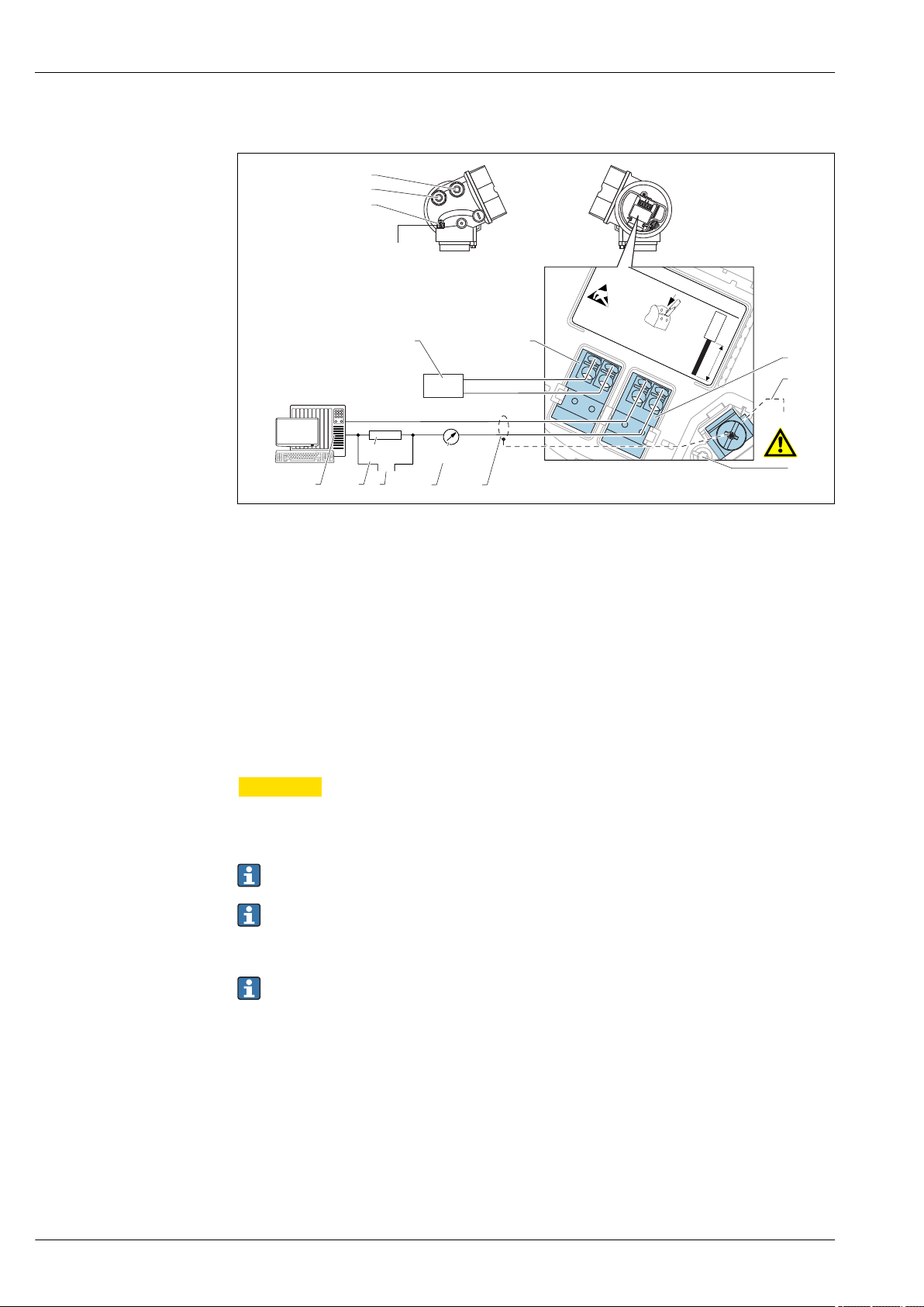
Micropilot FMR51, FMR52
3
1
+
L
4
2
4...20 mA
HART
90...253 V~
10 mm
Spare part
71108xxx
2- wire
4-20 mA
HART
[09]
open
-
N
A
13
12
11
910
6
7
8
!
!
2
3
4
5
1
+
-
4...20 mA
≥250 Ω
4-wire: 4-20mA HART (90 to 253 VAC)
6 Terminal assignment 4-wire; 4-20mA HART (90 to 253 VAC)
1 Evaluation unit, e.g. PLC
2 HART communication resistor (≥ 250 Ω): Observe maximum load
3 Connection for Commubox FXA195 or FieldXpert SFX350/SFX370 (via VIATOR Bluetooth modem)
4 Analog display device: Observe maximum load
5 Signal cable including screening (if required), observe cable specification
6 Protective connection; do not disconnect!
7 Protective earth, observe cable specification
8 4...20mA HART (active): Terminals 3 and 4
9 Supply voltage: Terminals 1 and 2
10 Supply voltage: Observe terminal voltage, observe cable specification
11 Terminal for potential equalization
12 Cable entry for signal line
13 Cable entry for power supply
A0018965
CAUTION
L
To ensure electrical safety:
Do not disconnect the protective connection (6).
‣
Disconnect the supply voltage before disconnecting the protective earth (7).
‣
Connect protective earth to the internal ground terminal (7) before connecting the supply
voltage. If necessary, connect the potential matching line to the external ground terminal (11).
In order to ensure electromagnetic compatibility (EMC): Do not only ground the device via the
protective earth conductor of the supply cable. Instead, the functional grounding must also be
connected to the process connection (flange or threaded connection) or to the external ground
terminal.
An easily accessible power switch must be installed in the proximity of the device. The power
switch must be marked as a disconnector for the device (IEC/EN61010).
24 Endress+Hauser
Page 25
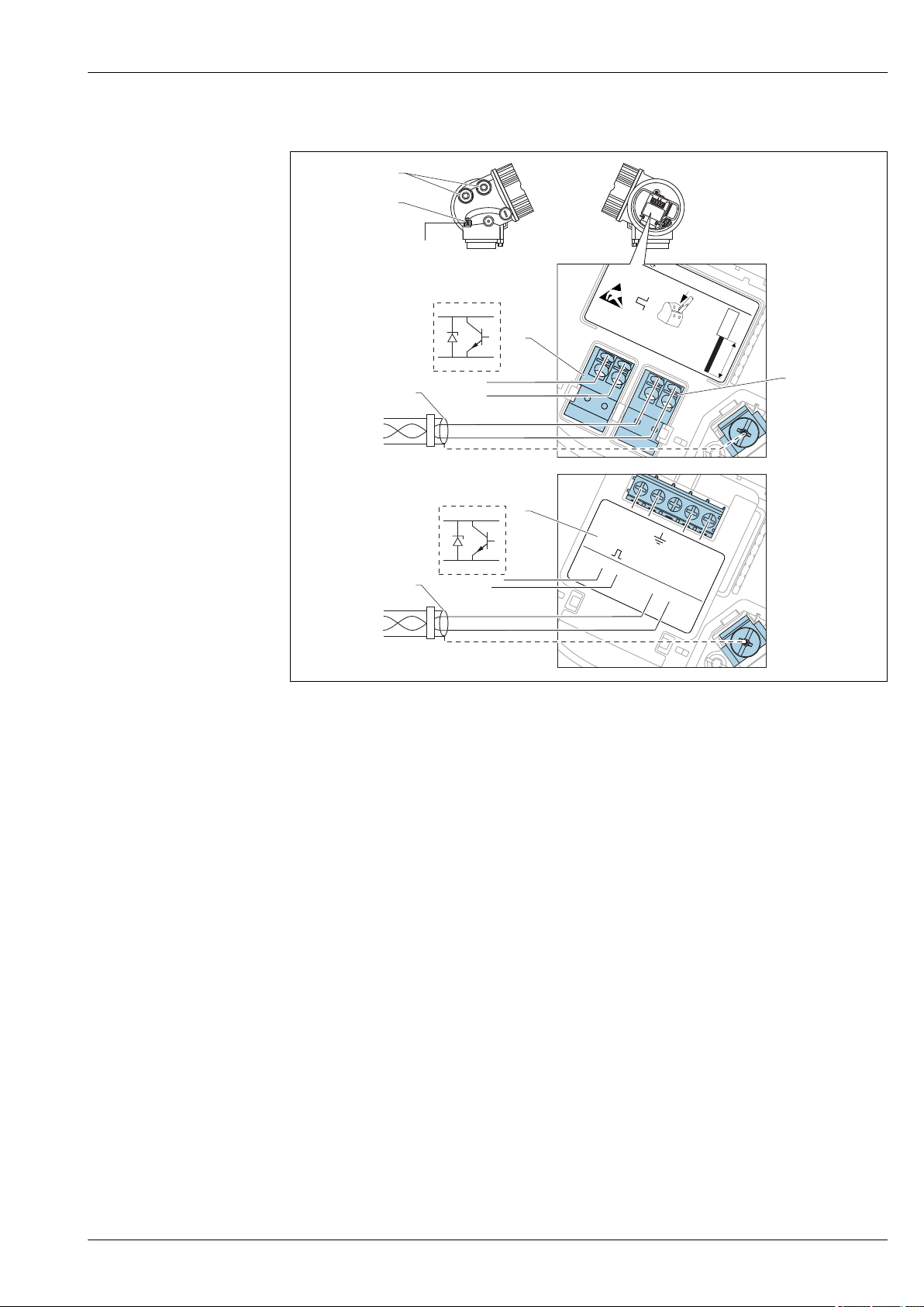
Micropilot FMR51, FMR52
1
3
+
+
2
4
FIELDBUS
2-channel overvoltage protection
-
-
[17]
4-20mA/
4-20mA/
B
1
1
+
+
2
2
FIELDBUS
Spare part
71023457
PA/FF
[06/07]
FIELDBUS
-
-
1
3
+
+
2
4
PA/FF
10 mm
Spare part
71108xxx
2- wire level
4-20 mA PFS
FIELDBUS
[26/27]
open
-
-
A
4
1
1
2
3
6
5
3+
3+
4-
4-
!
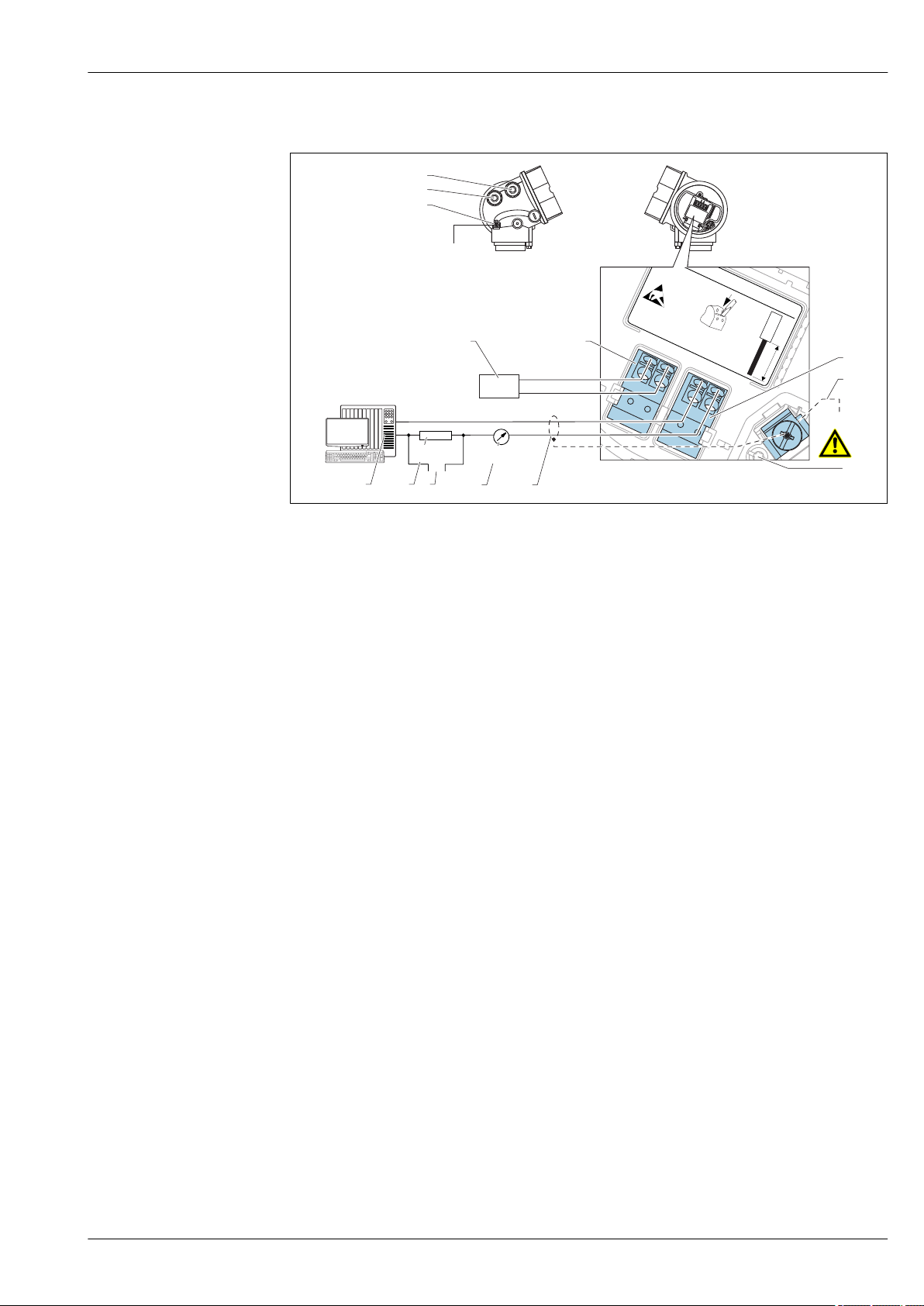
PROFIBUS PA / FOUNDATION Fieldbus
A0011341
7 Terminal assignment PROFIBUS PA / FOUNDATION Fieldbus
A Without integrated overvoltage protection
B With integrated overvoltage protection
1 Cable screen: Observe cable specifications
2 Switch output (open collector): Terminals 3 and 4
3 PROFIBUS PA / FOUNDATION Fieldbus: Terminals 1 and 2
4 Terminal for potential equalization line
5 Cable entries
6 Overvoltage protection module
Endress+Hauser 25
Page 26
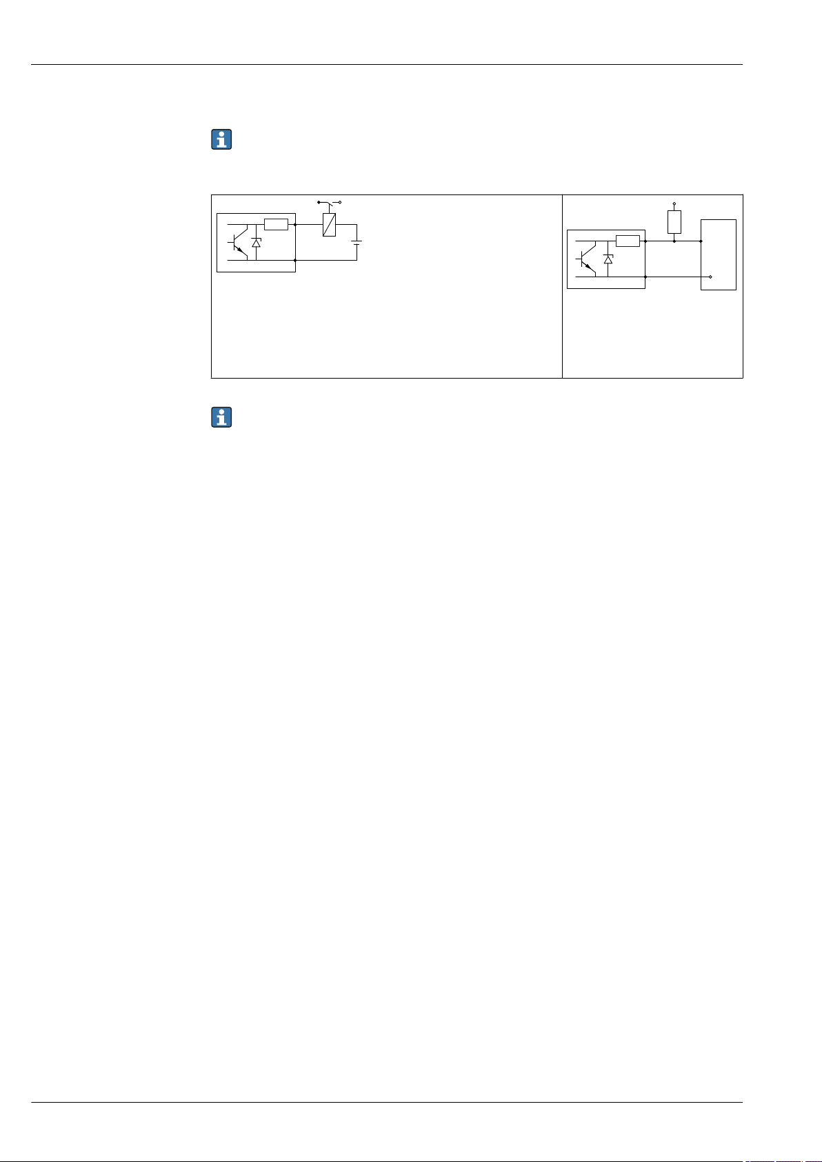
Micropilot FMR51, FMR52
3+
+
-
4-
R
i
3+
2
1
+
4-
R
i
Connection examples for the switch output
For HART devices, the switch output is available as an option. See product structure, feature 20:
"Power Supply, Output", option B: "2-wire; 4-20mA HART, switch output"
Devices with PROFIBUS PA and FOUNDATION Fieldbus always have a switch output.
A0015909
8 Connection of a relay
Suitable relays (examples):
• Solid-state relay: Phoenix Contact OV-24DC/480AC/5 with mounting
rail connector UMK-1 OM-R/AMS
• Electromechanical relay: Phoenix Contact PLC-RSC-12DC/21
For optimum interference immunity we recommend to connect an external resistor (internal
resistance of the relay or Pull-up resistor) of < 1 000 Ω.
9 Connection of a digital input
1 Pull-up resistor
2 Digital input
A0015910
26 Endress+Hauser
Page 27
Micropilot FMR51, FMR52
2
1
3
4
4
2
3
1
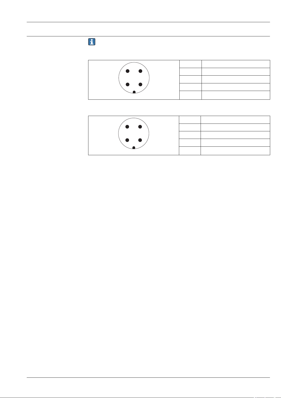
Device plug connectors
For the versions with fieldbus plug connector (M12 or 7/8"), the signal line can be connected
without opening the housing.
Pin assignment of the M12 plug connector
Pin Meaning
1 Signal +
2 not connected
3 Signal -
4 Ground
A0011175
Pin assignment of the 7/8" plug connector
Pin Meaning
1 Signal -
2 Signal +
3 Not connected
4 Screen
A0011176
Endress+Hauser 27
Page 28
Micropilot FMR51, FMR52
R [ ]?
U0[V]
10
10.4 21.4
20 30 35
0
500
U0[V]
10
13 24
20 30 35
0
500
R [ ]Ω
U0[V]
10
13 24
20 30 35
0
500
R [ ]Ω
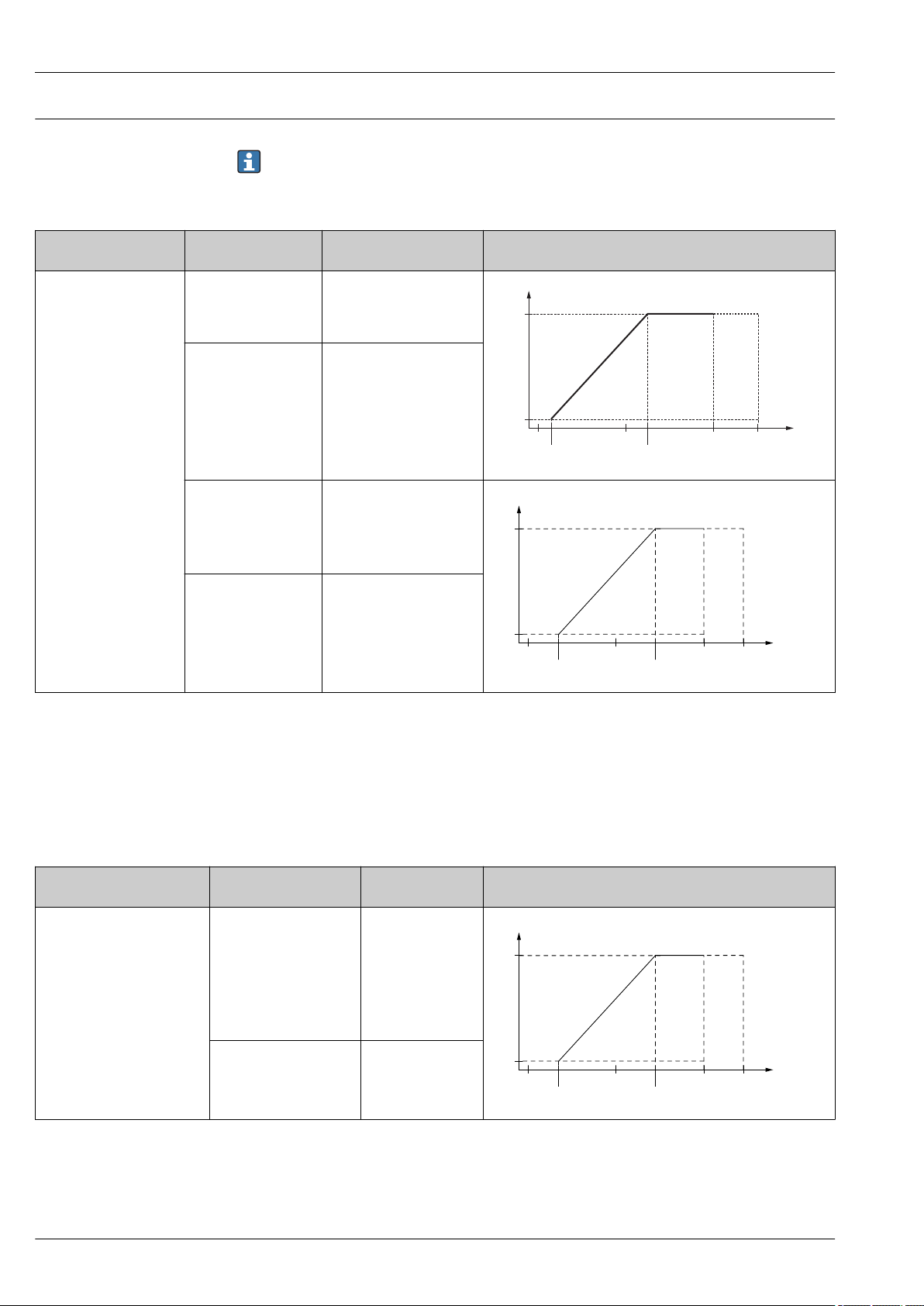
Supply voltage
"Power Supply, Output"
A: 2-wire; 4-20mA HART • Non-Ex
1)
"Approval"
• Ex nA
• Ex ic
• CSA GP
Ex ia / IS 10.4 to 30 V
• Ex d(ia) / XP
• Ex ic(ia)
• Ex nA(ia)
• Ex ta / DIP
Ex ia + Ex d(ia) / IS + XP 13 to 30 V
An external power supply is required.
Various supply units can be ordered from Endress+Hauser: see "Accessories" section→ 109
2-wire, 4-20mA HART, passive
2)
Terminal voltage U at the
device
10.4 to 35 V
13 to 35 V
3) 4)
3) 4)
5)
5)
Maximum load R, depending on the supply voltage U0 at the
supply unit
A0017140
1) Feature 020 of the product structure
2) Feature 010 of the product structure
3) For ambient temperatures Ta≤ -20 °C (-4 °F) a minimum voltage of 15 V is required for the sartup of the device at the MIN error current (3,6
mA). The startup current can be parametrized. If the device is operated with a fixed current I ≥ 5,5 mA (HART multidrop mode), a voltage of U ≥
10,4 V is sufficient throughout the entire range of ambient temperatures.
4) In the current simulation mode a voltage U ≥ 12.5 V is required.
5) For ambient temperatures Ta≤ -20 °C (-4 °F) a minimum voltage of 16 V is required for the startup of the device at the MIN error current (3.6
mA).
"Power Supply, Output"
B: 2-wire; 4-20 mA HART,
switch output
1)
"Approval"
• Non-Ex
• Ex nA
2)
Terminal voltage U
at the device
13 to 35 V
3)
Maximum load R, depending on the supply voltage U0 at the
supply unit
• Ex nA(ia)
• Ex ic
• Ex ic(ia)
• Ex d(ia) / XP
• Ex ta / DIP
• CSA GP
• Ex ia / IS
13 to 30 V
3)
• Ex ia + Ex d(ia) / IS + XP
1) Feature 020 of the product structure
2) Feature 010 of the product structure
3) For ambient temperatures Ta≤ -30 °C (-22 °F) a minimum voltage of 16 V is required for the startup of the device at the MIN error current (3.6
mA).
A0034771
A0034771
28 Endress+Hauser
Page 29
Micropilot FMR51, FMR52
R [ ]W
U0[V]
10
13 24
20 28
0
500
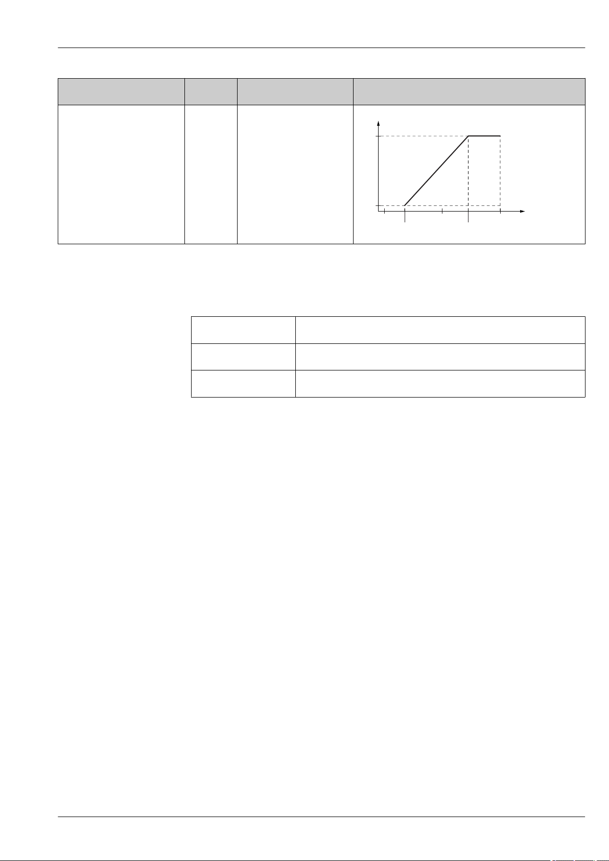
"Power Supply, Output"
C: 2-wire; 4-20mA HART,
1)
"Approval"
any 13 to 28 V
2)
Terminal voltage U at the
device
3)
Maximum load R, depending on the supply voltage U0 at the
supply unit
4-20mA
A0034841
1) Feature 020 of the product structure
2) Feature 010 of the product structure
3) For ambient temperatures Ta≤ -30 °C (-22 °F) a minimum voltage of 16 V is required for the startup of the device at the MIN error current (3.6
mA).
Polarity reversal
Yes
protection
Admissible residual ripple
USS < 1 V
at f = 0 to 100 Hz
Admissible residual ripple
USS < 10 mV
at f = 100 to 10000 Hz
Endress+Hauser 29
Page 30
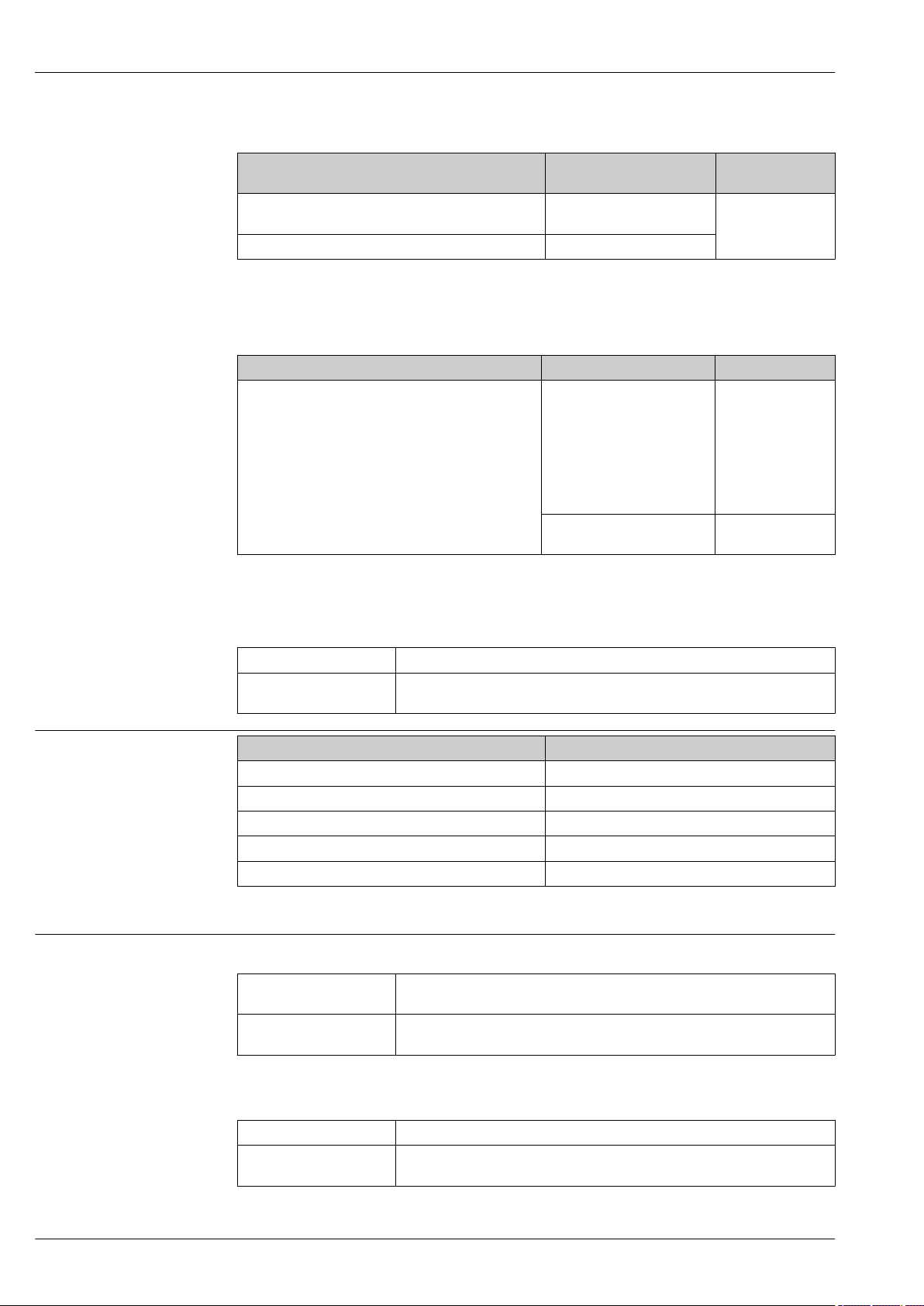
4-wire, 4-20mA HART, active
Micropilot FMR51, FMR52
"Power supply; Output"
1)
Terminal voltage Maximum load
K: 4-wire 90-253VAC; 4-20mA HART 90 to 253 VAC (50 to 60 Hz),
overvoltage category II
L: 4-wire 10,4-48VDC; 4-20mA HART 10.4 to 48 V
DC
1) Feature 020 of the product structure
PROFIBUS PA, FOUNDATION Fieldbus
"Power supply; Output"
1)
E: 2-wire; FOUNDATION Fieldbus, switch output
G: 2-wire; PROFIBUS PA, switch output
1) Feature 020 of the product structure
2) Feature 010 of the product structure
3) Input voltages up to 35 V will not spoil the device.
"Approval"
• Non-Ex
• Ex nA
• Ex nA(ia)
• Ex ic
• Ex ic(ia)
• Ex d(ia) / XP
• Ex ta / DIP
• CSA GP
• Ex ia / IS
• Ex ia + Ex d(ia) / IS + XP
2)
R
max
500 Ω
Terminal voltage
9 to 32 V
9 to 30 V
3)
3)
Polarity sensitive No
FISCO/FNICO compliant
according to IEC 60079-27
Power consumption
"Power supply; Output"
A: 2-wire; 4-20mA HART < 0.9 W
B: 2-wire; 4-20mA HART, switch output < 0.9 W
C: 2-wire; 4-20mA HART, 4-20mA < 2 x 0.7 W
K: 4-wire 90-253VAC; 4-20mA HART 6 VA
L: 4-wire 10,4-48VDC; 4-20mA HART 1.3 W
1) Feature 020 of the product structure
Current consumption HART
Nominal current 3.6 to 22 mA, the start-up current for multidrop mode can be parametrized (is
Breakdown signal
(NAMUR NE43)
PROFIBUS PA
Yes
1)
set to 3.6 mA on delivery)
adjustable: 3.59 to 22.5 mA
Power consumption
Nominal current 14 mA
Error current FDE (Fault
0 mA
Disconnection Electronic)
30 Endress+Hauser
Page 31
Micropilot FMR51, FMR52
FOUNDATION Fieldbus
Device basic current 15 mA
Error current FDE (Fault
Disconnection Electronic)
0 mA
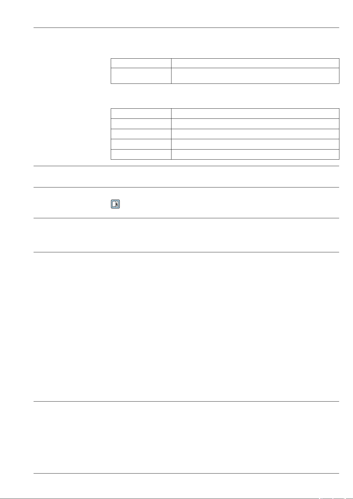
FISCO
Power supply failure
U
i
I
i
P
i
C
i
L
i
• Configuration is retained in the HistoROM (EEPROM).
17.5 V
550 mA
5.5 W
5 nF
10 μH
• Error messages (incl. value of operated hours counter) are stored.
Potential equalization
No special measures for potential equalization are required.
If the device is designed for hazardous areas, observe the information in the documentation
"Safety Instructions" (XA).
Terminals
• Without integrated overvoltage protection
Plug-in spring terminals for wire cross-sections 0.5 to 2.5 mm2 (20 to 14 AWG)
• With integrated overvoltage protection
Screw terminals for wire cross-sections 0.2 to 2.5 mm2 (24 to 14 AWG)
Cable entries Connection of power supply and signal line
To be selected in feature 050 "Electrical connection"
• Gland M20; Material dependent on the approval:
– For Non-Ex, ATEX, IECEx, NEPSI Ex ia/ic:
Plastics M20x1.5 for cable ⌀5 to 10 mm (0.2 to 0.39 in)
– For Dust-Ex, FM IS, CSA IS, CSA GP, Ex nA:
– For Ex d:
No gland available
• Thread
– ½" NPT
– G ½"
– M20 × 1.5
• Plug M12 / Plug 7/8"
Only available for Non-Ex, Ex ic, Ex ia
Connection of remote display FHX50
Dependent on feature 030: "Display, Operation":
• "Prepared for display FHX50 + M12 connection":
M12 socket
• "Prepared for display FHX50 + custom connection":
M16 cable gland
Cable specification
• Devices without integrated overvoltage protection
Pluggable spring-force terminals for wire cross-sections 0.5 to 2.5 mm2 (20 to 14 AWG)
• Devices with integrated overvoltage protection
Screw terminals for wire cross-sections 0.2 to 2.5 mm2 (24 to 14 AWG)
• For ambient temperature TU≥60 °C (140 °F): use cable for temperature TU +20 K.
Endress+Hauser 31
Page 32
Micropilot FMR51, FMR52
HART
• A normal device cable suffices if only the analog signal is used.
• A shielded cable is recommended if using the HART protocol. Observe grounding concept of the
plant.
• For 4-wire devices: Standard device cable is sufficient for the power line.
PROFIBUS
Use a twisted, screened two-wire cable, preferably cable type A.
For further information on the cable specifications, see Operating Instructions BA00034S
"PROFIBUS DP/PA: Guidelines for planning and commissioning", PNO Guideline 2.092
"PROFIBUS PA User and Installation Guideline" and IEC 61158-2 (MBP).
FOUNDATION Fieldbus
Endress+Hauser recommends using twisted, shielded two-wire cables.
For further information on the cable specifications, see Operating Instructions BA00013S
"FOUNDATION Fieldbus Overview", FOUNDATION Fieldbus Guideline and IEC 61158-2 (MBP).
Overvoltage protection
If the measuring device is used for level measurement in flammable liquids which requires the use of
overvoltage protection according to DIN EN 60079-14, standard for
test procedures 60060-1 (10 kA, pulse 8/20 μs), overvoltage protection has to be ensured by an
integrated or external overvoltage protection module.
Integrated overvoltage protection
An integrated overvoltage protection module is available for 2-wire HART as well as PROFIBUS PA
and FOUNDATION Fieldbus devices.
Product structure: Feature 610 "Accessory mounted", option NA "Overvoltage protection".
Technical data
Resistance per channel 2 × 0.5 Ω max.
Threshold DC voltage 400 to 700 V
Threshold impulse voltage < 800 V
Capacitance at 1 MHz < 1.5 pF
Nominal arrest impulse voltage (8/20 μs) 10 kA
External overvoltage protection
HAW562 or HAW569 from Endress+Hauser are suited as external overvoltage protection.
For detailed information please refer to the following documents:
• HAW562: TI01012K
• HAW569: TI01013K
32 Endress+Hauser
Page 33
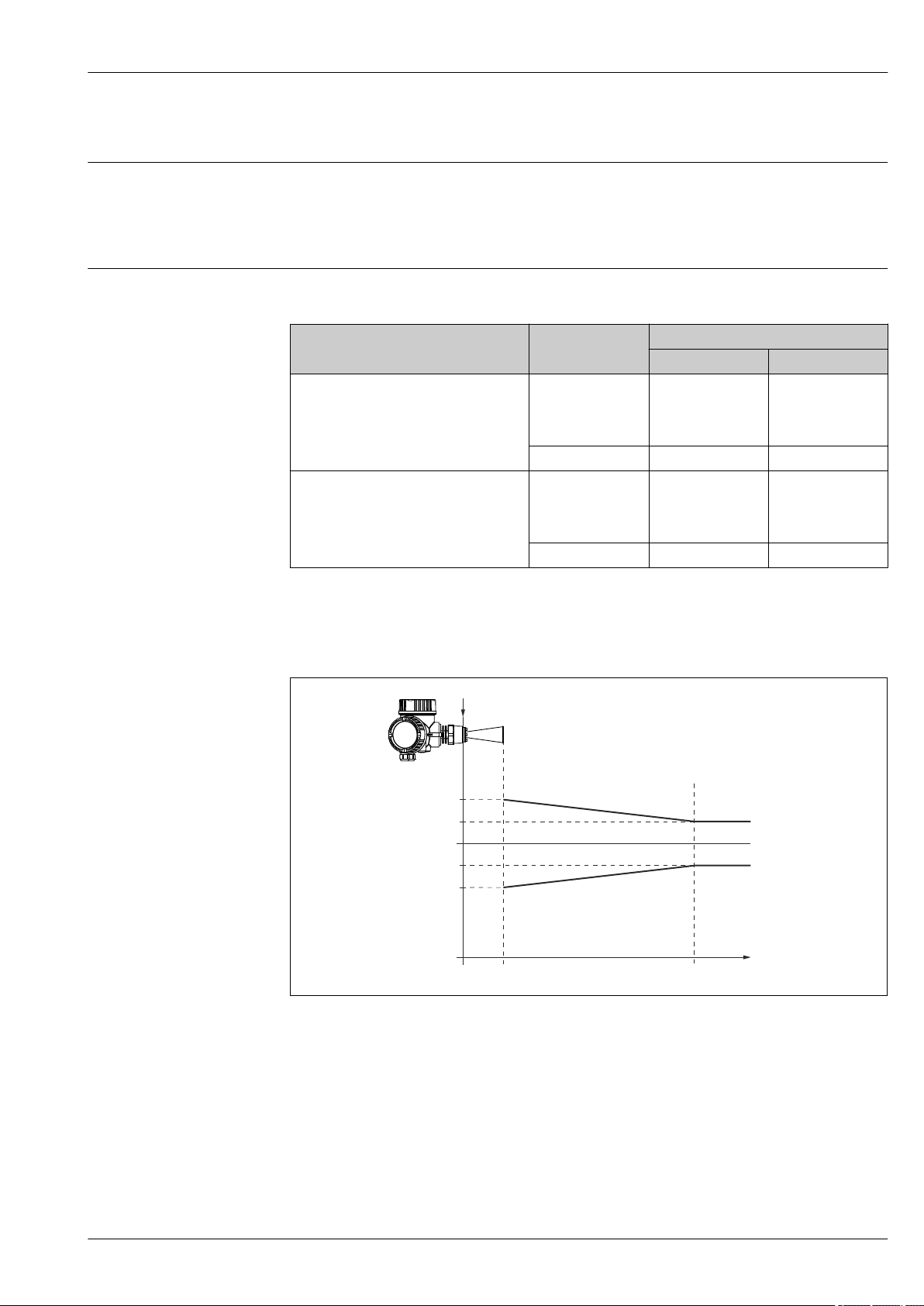
Micropilot FMR51, FMR52
2 (0.08)
0
-2 (-0.08)
A 1 (3.3)
4 (0.16)
-4 (-0.16)
R
D [mm] ([in])
D [m] ([ft])
Performance characteristics
Reference operating conditions
Maximum measured error
• Temperature = +24 °C (+75 °F) ±5 °C (±9 °F)
• Pressure = 960 mbar abs. (14 psia) ±100 mbar (±1.45 psi)
• Humidity = 60 % ±15 %
• Reflector: metal plate with a minimum diameter of 1 m (40 in)
• No major interference reflections inside the signal beam
Typical data under reference operating conditions: DIN EN IEC 61298-2 / DIN EN IEC 60770-1;
percentage values in relation to the span.
Device Value Output
digital analog
FMR51/FMR52
Standard version
FMR51/FMR52
Version with application package
"Advanced dynamics"
1) Only relevant for 4-20mA current output; add error of the analog value to the digital value.
2) Product structure: Feature 540 "Application Package", Option EM "Advanced dynamics"
2)
Sum of nonlinearity,
nonrepeatability and
hysteresis
Offset/Zero ± 4 mm (0.2 in) ± 0.03 %
Sum of nonlinearity,
nonrepeatability and
hysteresis
Offset/Zero ± 4 mm (0.2 in) ± 0.03 %
± 2 mm (0.08 in) ± 0.02 %
± 3 mm (0.12 in) ± 0.02 %
1)
Differing values in near-range applications
A0019035
10 Maximum measured error in near-range applications; values for standard version
Δ Maximum measured error
A Lower edge of the antenna
D Distance from the lower edge A of the antenna
R Reference point of the distance measurement
Endress+Hauser 33
Page 34
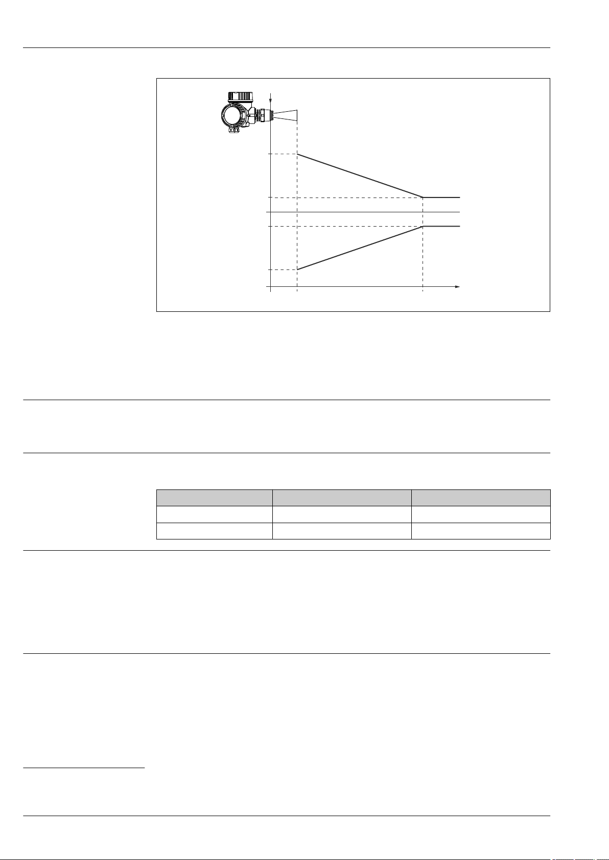
Micropilot FMR51, FMR52
3 (0.12)
0
-3 (-12)
A 2 (6.6) D [m] ([ft])
20 (0.79)
-20 (-0.79)
R
D [mm] ([in])
11 Maximum measured error in near-range applications; values for version with the "Advanced dynamics"
application package
Δ Maximum measured error
A Lower edge of the antenna
D Distance from the lower edge A of the antenna
R Reference point of the distance measurement
A0019034
Measured value resolution
Reaction time
Influence of ambient temperature
Influence of gas layer
Dead band according to DIN EN IEC 61298-2 / DIN EN IEC 60770-1:
• digital: 1 mm
• analog: 1 μA
The reaction time can be parametrized. The following step response times (as per DIN EN IEC
61298-2 / DIN EN IEC 60770-1)
Tank height Sampling rate Step response time
< 10 m (33 ft) ≥ 3.6 s
< 70 m (230 ft) ≥ 2.2 s
1)
are valid if the damping is switched off:
–1
–1
< 0.8 s
< 1 s
The measurements are carried out in accordance with DIN EN IEC 61298-3 / DIN EN IEC
60770-1
• Digital (HART, PROFIBUS PA, FOUNDATION Fieldbus):
– Standard version: average TK = 2 mm/10 K
– Version with advanced dynamics
2)
: average TK = 3 mm/10 K
• Analog (current output):
– zero point (4 mA): average TK = 0.02 %/10 K
– span (20 mA): average TK = 0.05 %/10 K
High pressures reduce the propagation velocity of the measuring signals in the gas/vapor above the
fluid. This effect depends on the kind of gas/vapor and of its temperature. This results in a
systematic measuring error that gets bigger as the distance increases between the reference point of
the measurement (flange) and the product surface. The following table illustrates this measured
1) According to DIN EN IEC 61298-2 / DIN EN IEC 60770-1 the response time is the time which passes after a sudden change of the input signal
until the output signal for the first time assumes 90% of the steady-state value.
2) Feature 540 "Application Package", option EM
34 Endress+Hauser
Page 35
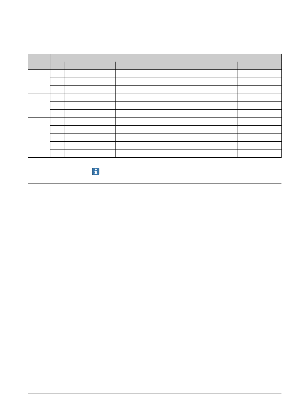
Micropilot FMR51, FMR52
error for a few typical gases/vapors (with regard to distance; a positive value means that too large a
distance is being measured):
Gas layer Temperature Pressure
°C °F 1 bar (14,5 psi) 10 bar (145 psi) 50 bar (725 psi) 100 bar (1450 psi) 160 bar (2320 psi)
Air/
Nitrogen
Hydrogen 20 68 –0.01 % 0.10 % 0.61 % 1.2 % 2.00 %
Water
(saturated
steam)
20 68 0.00 % 0.22 % 1.2 % 2.4 % 3.89 %
200 392 –0.01 % 0.13 % 0.74 % 1.5 % 2.42 %
400 752 –0.02 % 0.08 % 0.52 % 1.1 % 1.70 %
200 392 –0.02 % 0.05 % 0.37 % 0.76 % 1.23 %
400 752 –0.02 % 0.03 % 0.25 % 0.53 % 0.86 %
100 212 0.02 % - - - -
180 356 - 2.1 % - - -
263 505,4 - - 8.6 % - -
310 590 - - - 22 % -
364 687 - - - - 41.8 %
Gas phase compensation with external pressure sensor (PROFIBUS PA, FOUNDATION Fieldbus)
When the pressure is known and constant, this measured error can, for example, be
compensated by means of a linearization.
PROFIBUS devices can receive the signal of an external pressure sensor through the bus and use it to
perform a pressure dependent time-of-flight correction. In the case of saturated steam in the
temperature range from 100 to 350 °C (212 to 662 °f), for example, the measuring error of the
distance measurement can be reduced by this method from up to 29 % (without compensation) to
less than 3 % (with compensation).
Endress+Hauser 35
Page 36
Installation
A
1 2 3
Installation conditions Mounting position
Micropilot FMR51, FMR52
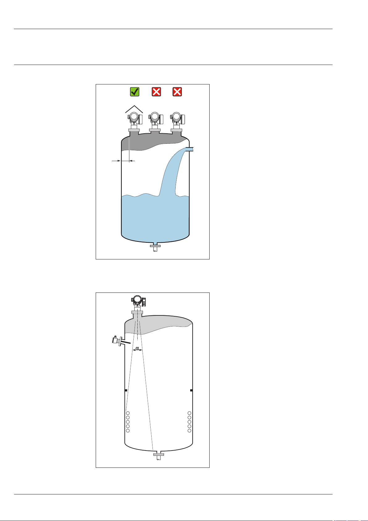
• Recommended distance A from wall to outer
edge of nozzle: ~ 1/6 of tank diameter.
Nevertheless the device should not be
installed closer than 15 cm (5.91 in) to the
tank wall.
• Not in the center (2), as interference can
cause signal loss.
• Not above the fill stream (3).
• It is recommended to us a weather protection
cover (1) in order to protect the device from
direct sun or rain.
A0016882
Vessel installations
Avoid any installations (point level switches,
temperature sensors, braces, vacuum rings,
heating coils, baffles etc.) inside the signal
beam. Take into account the beam angle
→ 38.
A0018944
36 Endress+Hauser
Page 37
Micropilot FMR51, FMR52
2
3
1
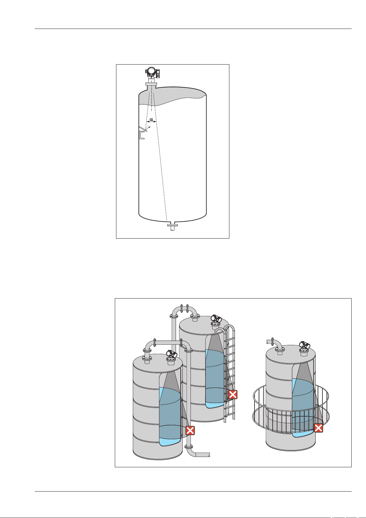
Reduction of interference echoes
Metallic screens mounted at a slope spread the
radar signal and can, therefore, reduce
interference echoes.
A0016890
Measurement in a plastic vessel
If the outer wall of the vessel is made of a non-conductive material (e.g. GRP), microwaves can also
be reflected off interfering installations outside the vessel (e.g. metallic pipes (1), ladders (2), grates
(3), ...). Therefore, there should be no such interfering installations in the signal beam. Please
contact Endress+Hauser for further information.
A0017123
Endress+Hauser 37
Page 38
Micropilot FMR51, FMR52
a
D
W
a
D
_
=
2
2
. .
tan
W
Optimization options
• Antenna size
The bigger the antenna, the smaller the beam angle α and the fewer interference echoes
→ 38.
• Mapping
The measurement can be optimized by means of electronic suppression of interference echoes.
• Antenna alignment
Take into account the marker on the flange or threaded connection → 41 → 44.
• Stilling well
A stilling well can be applied to avoid interferences → 45.
• Metallic screens mounted at a slope
They spread the radar signals and can, therefore, reduce interference echoes.
Beam angle
A0016891
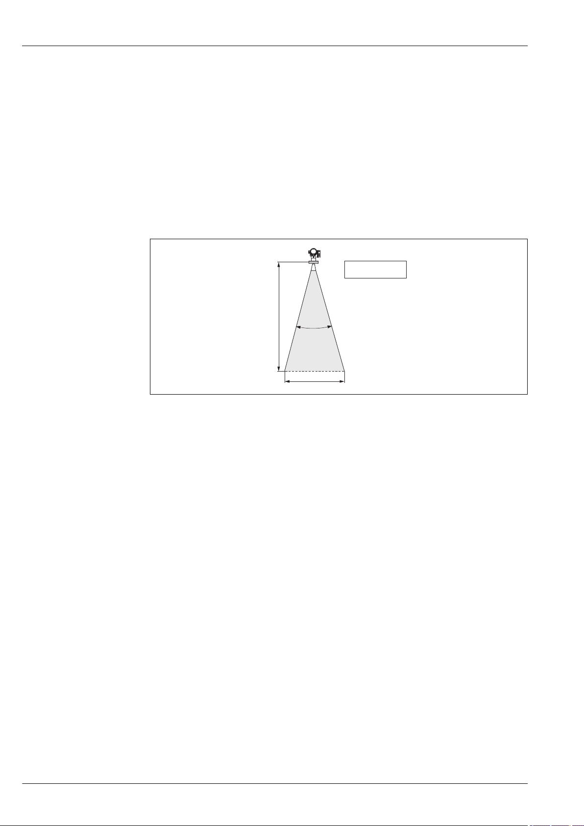
12 Relationship between beam angle α, distance D and beamwidth diameter W
The beam angle is defined as the angle α where the energy density of the radar waves reaches half
the value of the maximum energy density (3-dB-width). Microwaves are also emitted outside the
signal beam and can be reflected off interfering installations.
38 Endress+Hauser
Page 39
Micropilot FMR51, FMR52
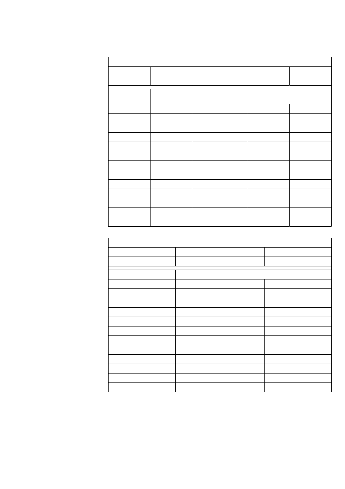
Beam diameter W as a function of beam angle α and measuring distance D:
FMR51
Antenna size 40 mm (1½ in) 50 mm (2 in) 80 mm (3 in) 100 mm (4 in)
Beam angle α 23° 18° 10° 8°
Measuring
distance (D)
3 m (9.8 ft) 1.22 m (4 ft) 0.95 m (3.1 ft) 0.53 m (1.7 ft) 0.42 m (1.4 ft)
6 m (20 ft) 2.44 m (8 ft) 1.9 m (6.2 ft) 1.05 m (3.4 ft) 0.84 m (2.8 ft)
9 m (30 ft) 3.66 m (12 ft) 2.85 m (9.4 ft) 1.58 m (5.2 ft) 1.26 m (4.1 ft)
12 m (39 ft) 4.88 m (16 ft) 3.80 m (12 ft) 2.1 m (6.9 ft) 1.68 m (5.5 ft)
15 m (49 ft) 6.1 m (20 ft) 4.75 m (16 ft) 2.63 m (8.6 ft) 2.10 m (6.9 ft)
20 m (66 ft) 8.14 m (27 ft) 6.34 m (21 ft) 3.50 m (11 ft) 2.80 m (9.2 ft)
25 m (82 ft) 10.17 m (33 ft) 7.92 m (26 ft) 4.37 m (14 ft) 3.50 m (11 ft)
30 m (98 ft) - 9.50 m (31 ft) 5.25 m (17 ft) 4.20 m (14 ft)
35 m (115 ft) - 11.09 m (36 ft) 6.12 m (20 ft) 4.89 m (16 ft)
40 m (131 ft) - 12.67 m (42 ft) 7.00 m (23 ft) 5.59 m (18 ft)
45 m (148 ft) - - 7.87 m (26 ft) 6.29 m (21 ft)
60 m (197 ft) - - 10.50 m (34 ft) 8.39 m (28 ft)
70 m (230 ft) - - - 9.79 m (32 ft)
Antenna size 50 mm (2 in) 80 mm (3 in)
Beam angle α 18° 10°
Beamwidth diameter W
FMR52
Measuring distance (D) Beamwidth diameter W
3 m (9.8 ft) 0.95 m (3.1 ft) 0.53 m (1.7 ft)
6 m (20 ft) 1.9 m (6.2 ft) 1.05 m (3.4 ft)
9 m (30 ft) 2.85 m (9.4 ft) 1.58 m (5.2 ft)
12 m (39 ft) 3.80 m (12 ft) 2.1 m (6.9 ft)
15 m (49 ft) 4.75 m (16 ft) 2.63 m (8.6 ft)
20 m (66 ft) 6.34 m (21 ft) 3.50 m (11 ft)
25 m (82 ft) 7.92 m (26 ft) 4.37 m (14 ft)
30 m (98 ft) 9.50 m (31 ft) 5.25 m (17 ft)
35 m (115 ft) 11.09 m (36 ft) 6.12 m (20 ft)
40 m (131 ft) 12.67 m (42 ft) 7.00 m (23 ft)
45 m (148 ft) - 7.87 m (26 ft)
60 m (197 ft) - 10.50 m (34 ft)
Endress+Hauser 39
Page 40
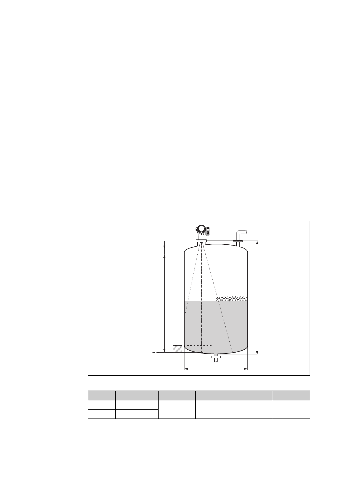
Micropilot FMR51, FMR52
100%
0%
B
A
C
H
øD
Measuring conditions
• In case of boiling surfaces, bubbling or tendency for foaming use FMR53 or FMR54. Depending
on its consistence, foam can either absorb microwaves or reflect them off the foam surface.
Measurement is possible under certain conditions. For FMR50, FMR51 and FMR52, the additional
option "Advanced dynamics" is recommended in these cases (feature 540: "Application Package",
option EM).
• In case of heavy steam development or condensate, the maximum measuring range of FMR50,
FMR51 and FMR52 may decrease depending on density, temperature and composition of the
steam → use FMR53 or FMR54.
• For the measurement of absorbing gases such as ammonia NH3 or some fluorocarbons
3)
, please
use Levelflex or Micropilot FMR54 in a stilling well.
• The measuring range begins, where the beam hits the tank bottom. Particularly with dish bottoms
or conical outlets the level cannot be detected below this point.
• In stilling well applications, the electromagnetic waves do not propagate completely outside the
tube. It must be taken into account that the accuracy may be reduced in the area C. In order to
guarantee the required accuracy in these cases, it is recommended to position the zero-point at a
distance C above the end of the tube (see figure).
• In case of media with a low dielectric constant (εr = 1.5 to 4)
4)
the tank bottom can be visible
through the medium at low levels (low height C). Reduced accuracy has to be expected in this
range. If this is not acceptable, we recommend positioning the zero point at a distance C (see
figure) above the tank bottom in these applications.
• In principle it is possible to measure up to the tip of the antenna with FMR51, FMR53 and FMR54.
However, due to considerations regarding corrosion and build-up, the end of the measuring range
should not be chosen any closer than A (see figure) to the tip of the antenna.
• When using FMR54 with planar antenna, especially for media with low dielectric constants, the
end of the measuring range should not be closer than A: 1 m (3.28 ft) to the flange.
• The smallest possible measuring range B depends on the antenna version (see figure).
• The tank height should be at least H (see table).
Device A [mm (in)] B [m (ft)] C [mm (in)] H [m (ft)]
FMR51 50(1.97)
3) Affected compounds are e.g. R134a, R227, Dymel 152a.
4) Dielectric constants of important media commonly used in various industries are summarized in the DC manual (CP01076F) and in the Endress
+Hauser "DC Values App" (available for Android and iOS).
40 Endress+Hauser
FMR52 200(7.87)
> 0.2 (0.7) 50 to 250 (1.97 to 9.84) > 0.3 (1.0)
A0018872
Page 41
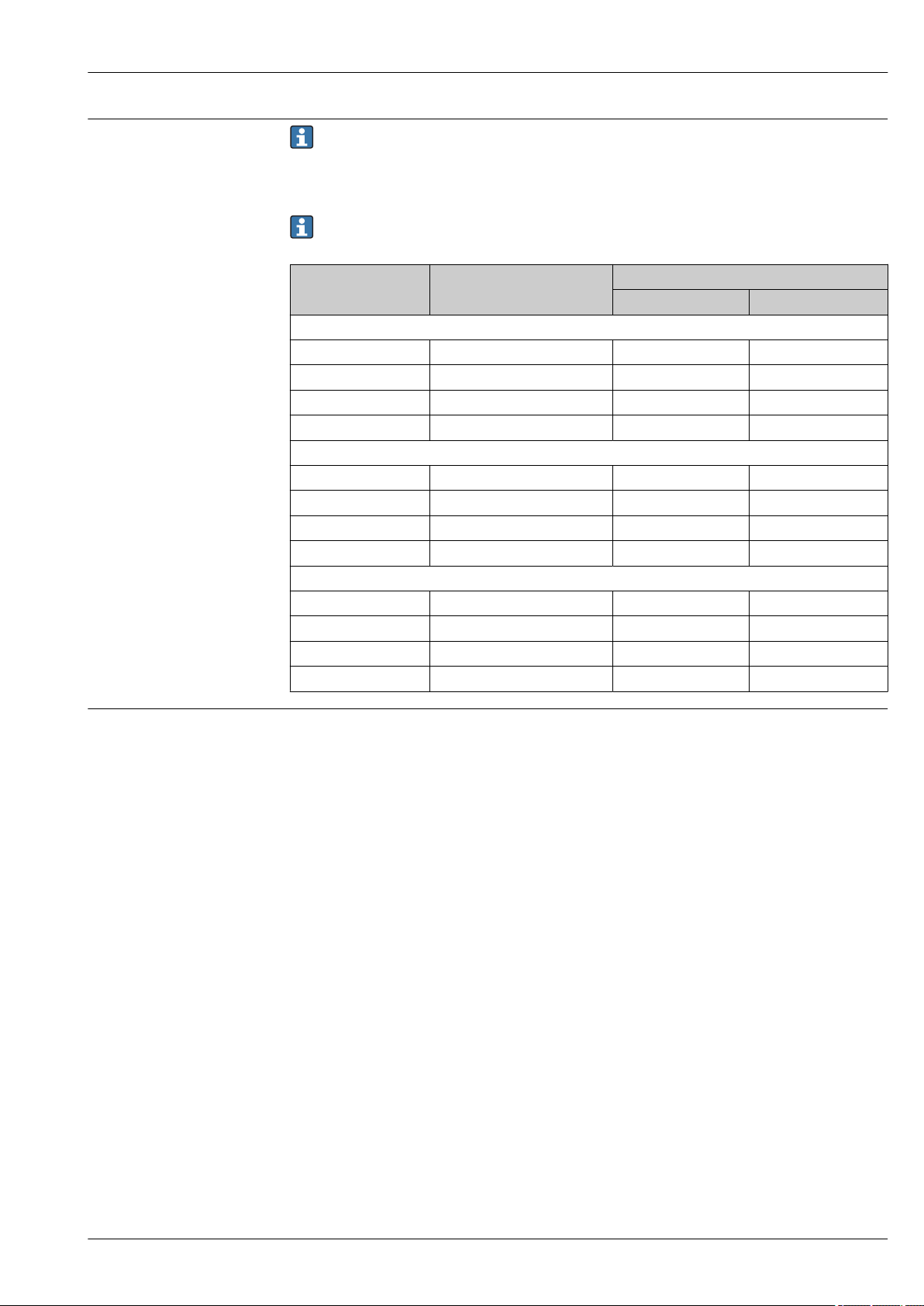
Micropilot FMR51, FMR52
Mounting cladded flanges
• Use flange screws according to the number of flange holes.
• Tighten the screws with the required torque (see table).
• Retighten the screws after 24 hours or after the first temperature cycle.
• Depending on process pressure and process temperature check and retighten the screws at
regular intervals.
Usually, the PTFE flange cladding also serves as a seal between the nozzle and the device
flange.
Flange size Number of screws Recommended torque [Nm]
minimum maximum
EN
DN50/PN16 4 45 65
DN80/PN16 8 40 55
DN100/PN16 8 40 60
DN150/PN16 8 75 115
ASME
2"/150lbs 4 40 55
3"/150lbs 4 65 95
4"/150lbs 8 45 70
6"/150lbs 8 85 125
JIS
10K 50A 4 40 60
10K 80A 8 25 35
10K 100A 8 35 55
10K 100A 8 75 115
Installation in vessel (free space)
Horn antenna (FMR51)
Alignment
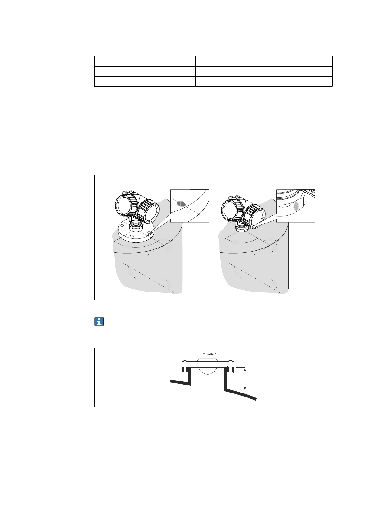
• Align the antenna vertically to the product surface.
The maximum range may be reduced if the horn antenna is not vertically aligned.
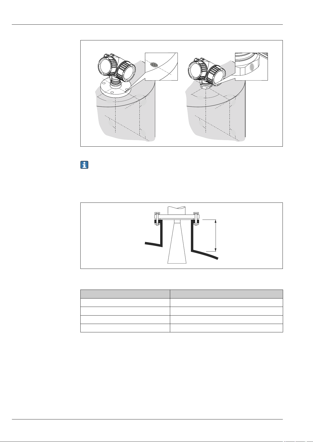
• A marking at the flange (somewhere between the flange holes) or the boss enables alignment of
the antenna. This marking must be aligned towards the tank wall as well as possible.
Endress+Hauser 41
Page 42
Micropilot FMR51, FMR52
90°
90°
90°
90°
90°
90°
90°
90°
90°
90°
A
B
H
max
Depending on the device version the marking may be a circle or two short parallel lines.
A0018974
Nozzle mounting
For optimum measurement, the tip of the antenna should extend below the nozzle. Depending on
the antenna size this is achieved by the following maximum nozzle heights:
13 Nozzle height for horn antenna (FMR51)
Antenna
BA: Horn 40mm/1-1/2" 86 mm (3.39 in)
BB: Horn 50mm/2" 115 mm (4.53 in)
BC: Horn 80mm/3" 211 mm (8.31 in)
BD Horn 100mm/4" 282 mm (11.1 in)
1)
Maximum nozzle height H
max
A0016820
1) Feature 070 of the product structure
Conditions for longer nozzles
If the medium has good reflective properties, higher nozzles can be accepted. In this case the
maximum nozzle height, H
42 Endress+Hauser
, is dependent on the nozzle diameter, D:
max
Page 43
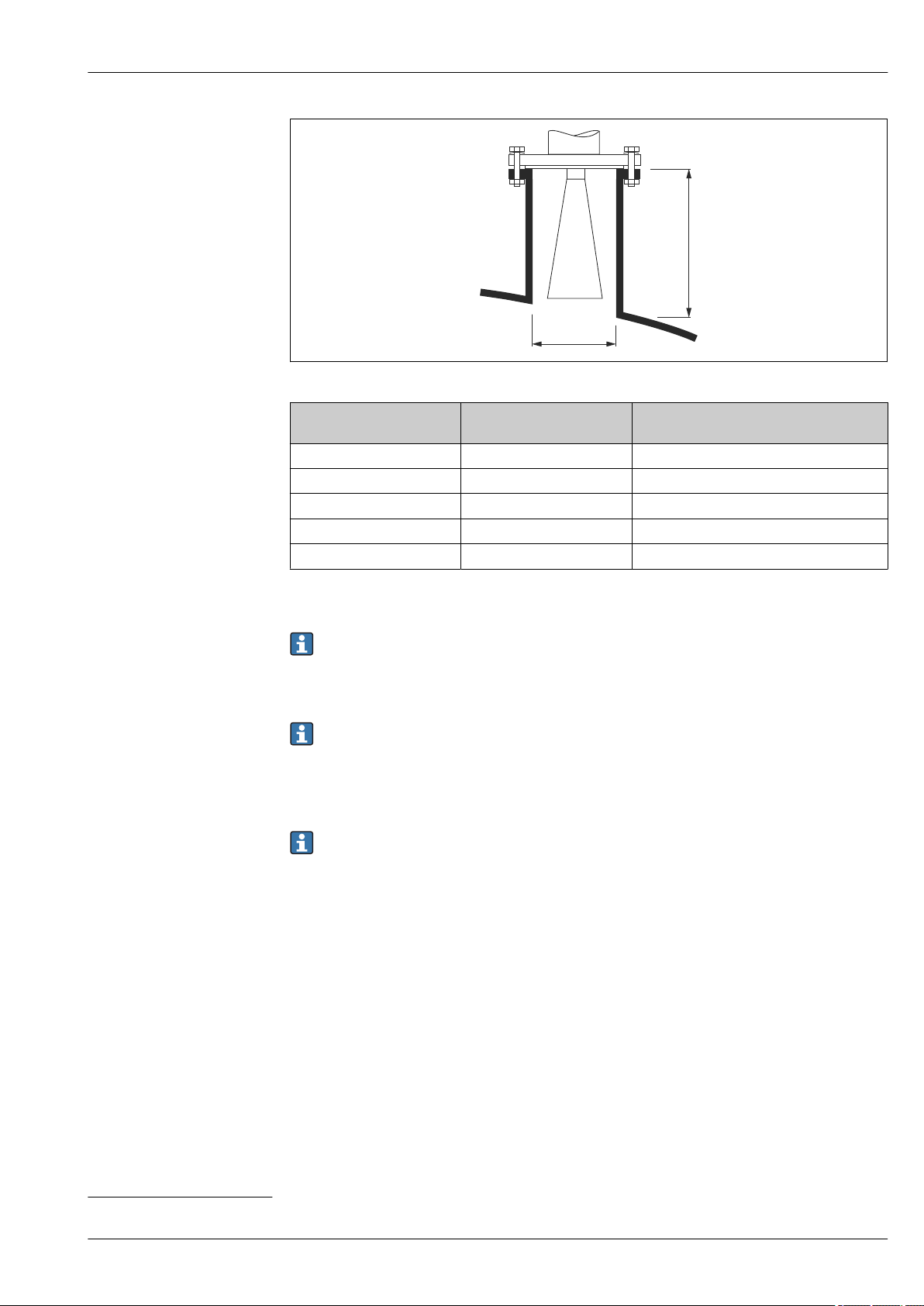
Micropilot FMR51, FMR52
H
max
øD
A0023611
Nozzle diameter D Maximum nozzle height
H
max
40 mm (1.5 in) 100 mm (3.9 in) BA: Horn 40mm/1-1/2"
50 mm (2 in) 150 mm (5.9 in) BB: Horn 50mm/2"
80 mm (3 in) 250 mm (9.8 in) BC: Horn 80mm/3"
100 mm (4 in) 500 mm (19.7 in) BD: Horn 100mm/4"
150 mm (6 in) 800 mm (31.5 in) BD: Horn 100mm/4"
1) Feature 070 of the product structure
Recommended antenna
1)
If the antenna doesn't extend below the nozzle, observe the following:
• The nozzle end must be smooth and free of burrs. If possible its edge should be rounded.
• An interference echo suppression must be performed.
• Please contact Endress+Hauser for applications with higher nozzles than those indicated in
the table.
• For mounting in heigh nozzles the device is available in a version with an antenna extension
of up to 1 000 mm (39.4 in)
5)
• The antenna extension may cause interference echoes in the near range. In this case it may
occur that the maximum measurable level is reduced.
Threaded connection
For devices with a threaded connection it may be necessary - depending on the antenna size to unmount the horn before fastening the device and to mount it again afterwards.
• Tighten with the hexagonal nut only.
• Tool : 55 mm hexagonal wrench
• Maximum permissible torque: 60 Nm (44 lbf ft)
Mesurement from the outside through plastic walls (FMR50/FMR51)
• Dielectric constant of the medium: εr > 10
• If possible, use an antenna 100 mm (4 in).
• The distance from the lower edge of the antenna to the tank ceiling should be about
100 mm (4 in).
• If possible, avoid mounting locations where condensation or build-up might occur.
• In case of outdoor mounting, the space between antenna and vessel has to be protected from the
elements.
• Do not mount any potential reflectors (e.g. pipes) outside the tank in the signal beam.
5) Feature 610 "Accessory mounted" of the product structure.
Endress+Hauser 43
Page 44
Micropilot FMR51, FMR52
90°
90°
90°
90°
90°
90°
90°
90°
90°
90°
A
B
H
max
Suitable thickness of the tank ceiling:
Penetrated material PE PTFE PP Perspex
DK / ε
r
Optimum thickness
1) Other possible values for the thickness are multiples of the values listed (e.g. for PE: 7,6 mm (0.3 in), 11,4
mm (0.45 in)
1)
Horn antenna, flush mount (FMR52)
Alignment
• Align the antenna vertically to the product surface.
The maximum range may be reduced if the horn antenna is not vertically aligned.
• A marking at the flange (somwhere between the flange holes) or the boss enables alignment of
the antenna. This marking must be aligned towards the tank wall as well as possible.
2.3 2.1 2.3 3.1
3.8 mm (0.15 in) 4.0 mm (0.16 in) 3.8 mm (0.15 in) 3.3 mm (0.13 in)
A0018974
Depending on the device version the marking may be a circle or two short parallel lines.
Nozzle mounting
14 Nozzle height for horn antenna, flush mount (FMR52)
A0016819
44 Endress+Hauser
Page 45
Micropilot FMR51, FMR52
1
90°
Installation in stilling well
Antenna
BO: Horn 50mm/2" 500 mm (19.7 in)
BP: Horn 80mm/3" 500 mm (19.7 in)
1) Feature 070 of the product structure
1)
Maximum nozzle height H
max
Please contact Endress+Hauser for applications with higher nozzle.
• For flanges with PTFE cladding: Observe the notes on the mounting of cladded flanges
→ 41.
• Usually, the PTFE flange cladding also serves as a seal between the nozzle and the device
flange.
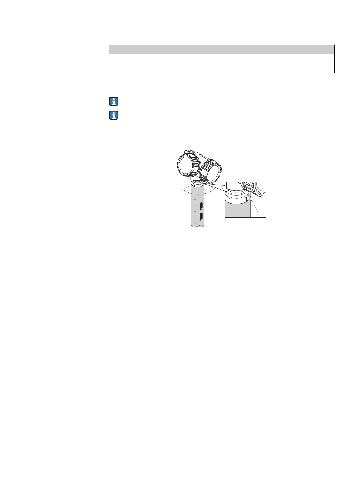
A0016841
15 Installation in stilling well
1 Marking for antenna alignment
• For horn antenna: Align the marking towards the slots of the stilling well.
• Measurements can be performed through an open full bore ball valve without any problems.
• After mounting, the housing can be turned 350° in order to facilitate access to the display and the
terminal compartment.
Recommendations for the stilling well
• Metal (no enamel coating; plastic on request).
• Constant diameter.
• Diameter of stilling well not larger than antenna diameter.
• Diameter difference between horn antenna and inner diameter of the stilling well as small as
possible.
• Weld seam as smooth as possible and on the same axis as the slots.
• Slots offset 180° (not 90°).
• Slot width or diameter of holes max. 1/10 of pipe diameter, de-burred. Length and number do not
have any influence on the measurement.
• Select horn antenna as big as possible. For intermedaite sizes (e.g. 180 mm (7 in)) select next
larger antenna and adapt it mechanically (for horn antennas)
• At any transition (i.e. when using a ball valve or mending pipe segments), no gap may be left
exceeding 1 mm (0.04 in).
• The stilling well must be smooth on the inside (average roughness Rz ≤ 6.3 μm (248 μin)). Use
extruded or parallel welded metal pipe. An extension of the pipe is possible with welded flanges or
pipe sleeves. Flange and pipe have to be properly aligned at the inside.
• Do not weld through the pipe wall. The inside of the stilling well must remain smooth. In case of
unintentional welding through the pipe, the weld seam and any unevenness on the inside need to
be carefully removed and smoothened. Otherwise, strong interference echoes will be generated
and material build-up will be promoted.
• In the case of smaller nominal widths flanges must be welded to the pipe such that they allow for a
correct orientation (marker aligned toward slots).
Endress+Hauser 45
Page 46
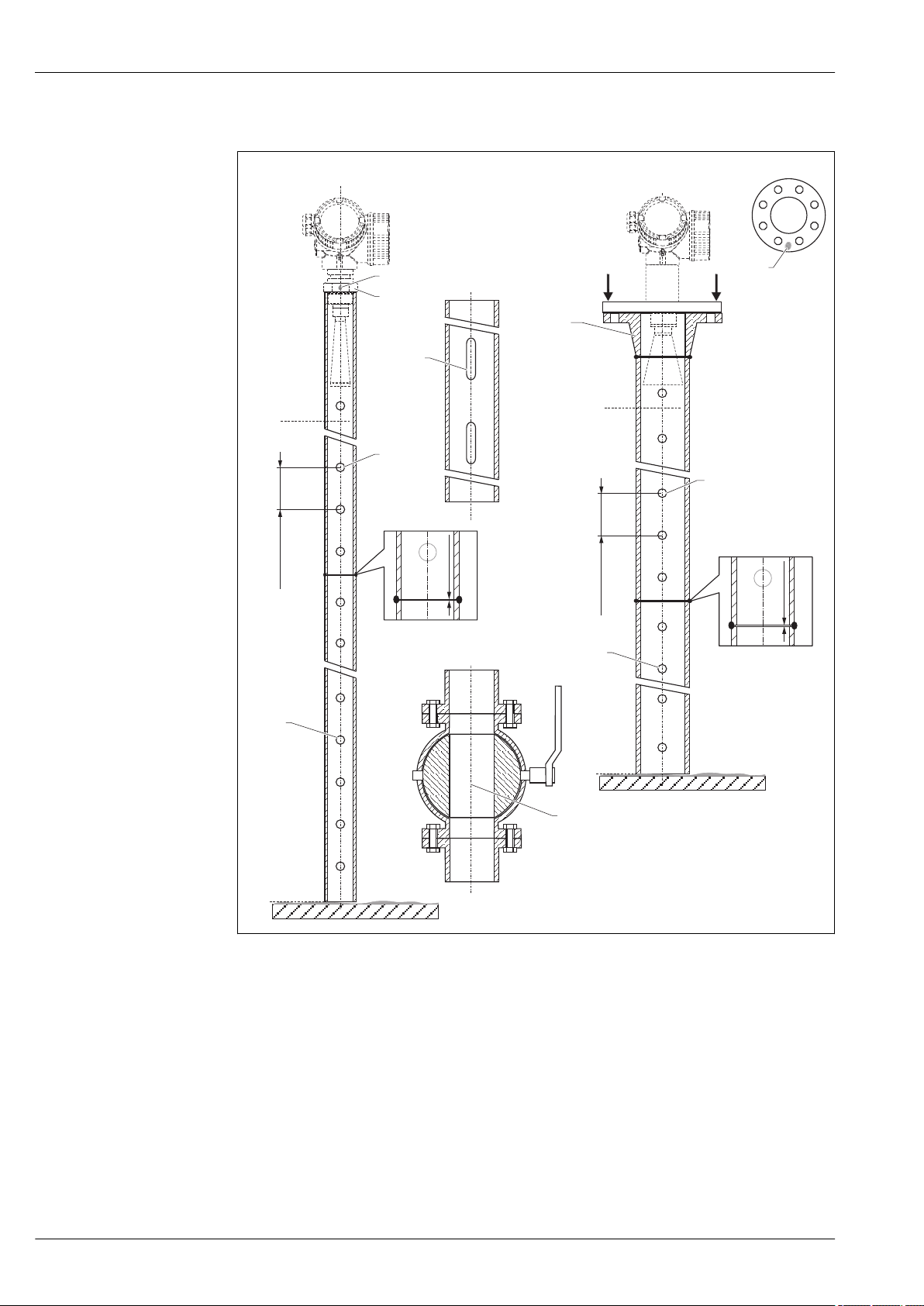
Examples for the construction of stilling wells
100%
0%
100%
0%
A
B
A A
A-A
150…500
(5.91...19.7)
150…500
(5.91...19.7)
mm (in)
2
1
4
4
C
D
5
6
6
7
1
3
1 (0.04)≤
1 (0.04)≤
Micropilot FMR51, FMR52
A0019009
A Micropilot FMR50/FMR51: Horn 40mm(1½")
B Micropilot FMR50/FMR51/FMR52/FMR54: Horn 80mm(3")
C Stilling well with slots
D Full bore ball valve
1 Marking for axial alignment
2 Threaded connection
3 e.g. welding neck flange DIN2633
4 hole max. 1/10 stilling well
5 hole max. 1/10 stilling well; single sided or drilled through
6 Inside of holes deburred
7 Diameter of opening of ball valve must always be equivalent to pipe diameter; avoid edges and constrictions.
46 Endress+Hauser
Page 47
Micropilot FMR51, FMR52
1
2
2
90°
90°
Installation in bypass
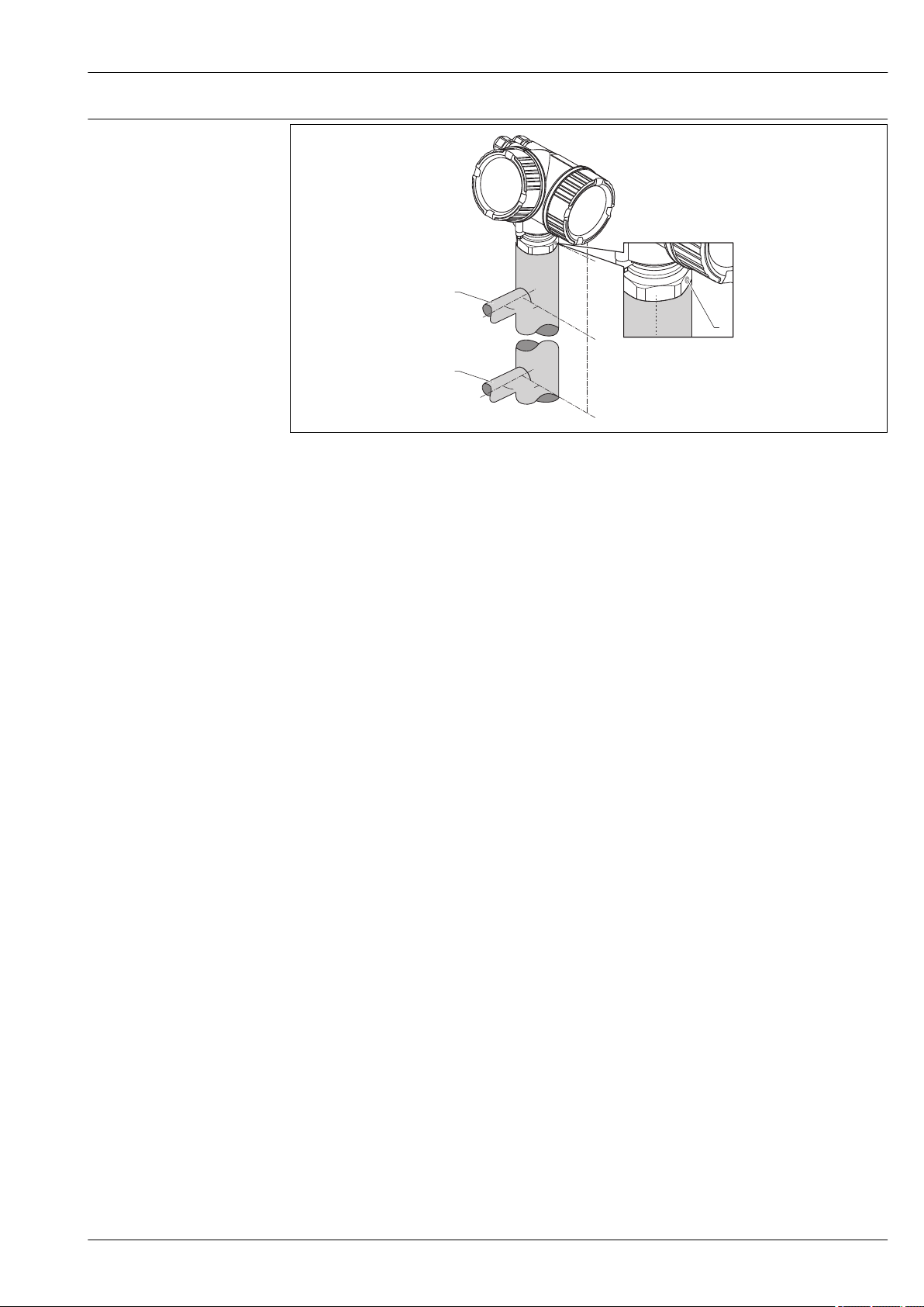
A0019446
16 Installation in bypass
1 Marking for antenna alignment
2 Tank connectors
• Alighn the marker perpendicular (90°) to the tank connectors.
• Measurements can be performed through an open full bore ball valve without any problems.
• After mounting, the housing can be turned 350° in order to simplify access to the display and the
terminal compartment.
Recommendations for the bypass pipe
• Metal (no plastic or enamel coating).
• Constant diameter.
• Select horn antenna as big as possible. For intermediate sizes (e.g. 95 mm (3.5 in)) select next
larger antenna and adapt it mechanically (for horn antennas).
• Diameter difference between horn antenna and inner diameter of the bypass as small as possible.
• At any transition (i.e. when using a ball valve or mending pipe segments), no gap may be created
exceeding 1 mm (0.04 in).
•
In the area of the tank connections (~ ±20 cm (7.87 in)) a reduced accuracy of the measurement
has to be expected.
Endress+Hauser 47
Page 48
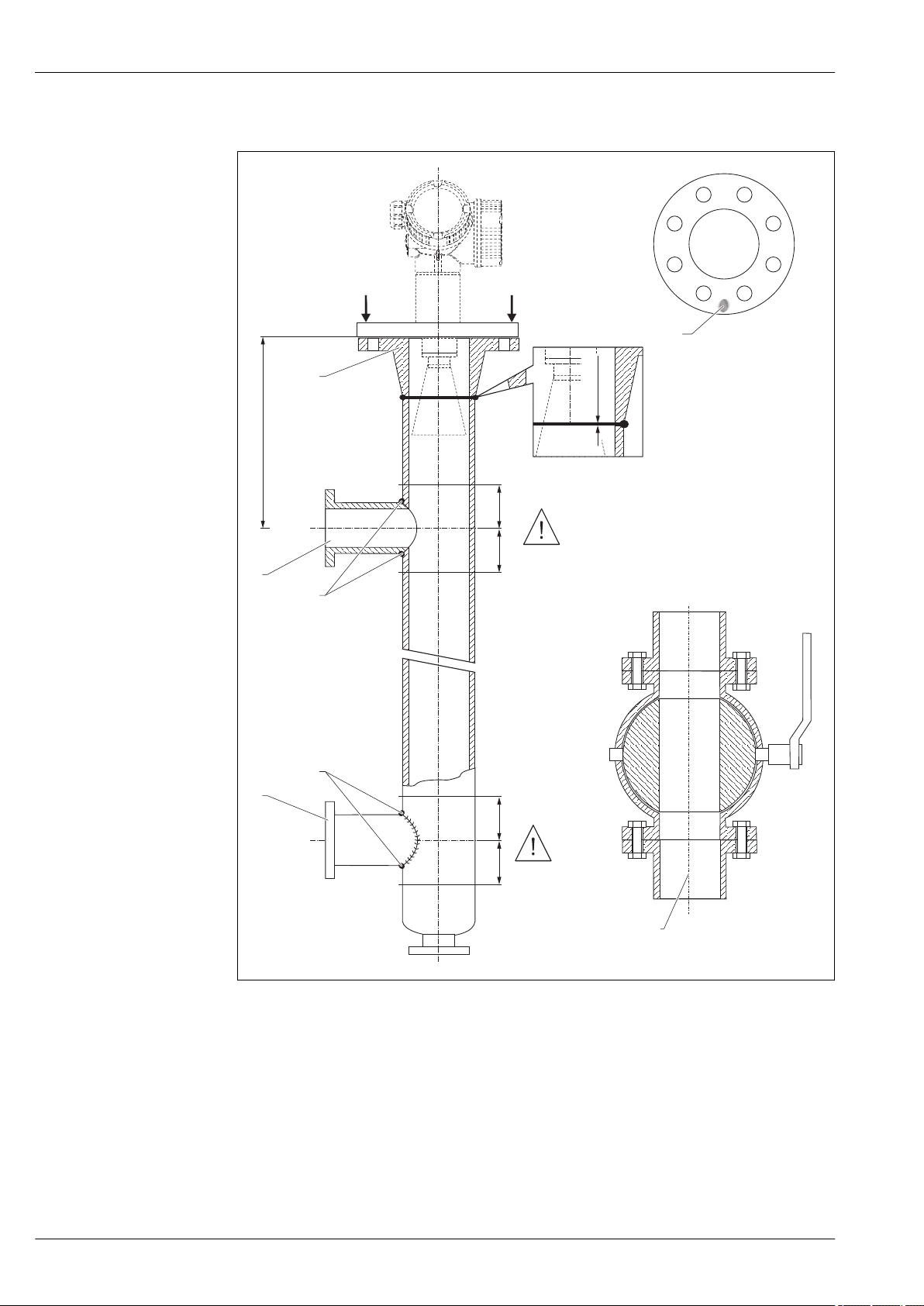
Micropilot FMR51, FMR52
100%
0%
A
A A
A-A
mm (in)
200
(7.87)
200
(7.87)
200
(7.87)
200
(7.87)
B
5
4
4
1
2
C
3
3
≤ 1 (0.04)
Example for the construction of a bypass
A Micropilot FMR50/FMR51/FMR52/FMR54: Horn 80mm(3")
B Full bore ball valve
C Minimum distance to upper connection pipe: 400 mm (15,7 in)
1 Marking for axial alignment
2 e.g. welding neck flange DIN2633
3 Diameter of the connection pipes as small as possible
4 Do not weld through the pipe wall; the inside of the bypass must remain smooth.
5 Diameter of opening of ball valve must always be equivalent to pipe diameter. Avoid edges and constrictions.
A0019010
48 Endress+Hauser
Page 49
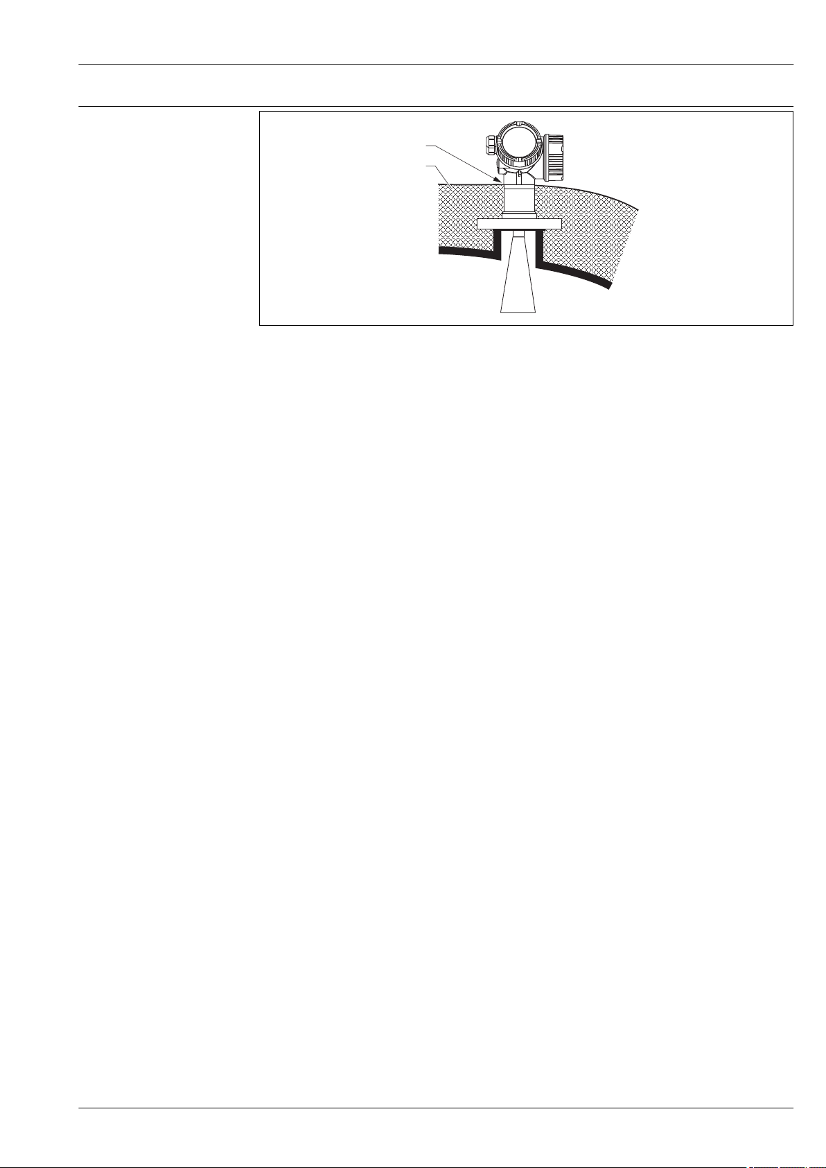
Micropilot FMR51, FMR52
1
2
Vessels with heat insulation
A0019142
If process temperatures are high, the device must be included in normal tank insulation to prevent
the electronics heating up as a result of heat radiation or convection. The insulation may not exceed
beyond the neck of the housing.
Endress+Hauser 49
Page 50
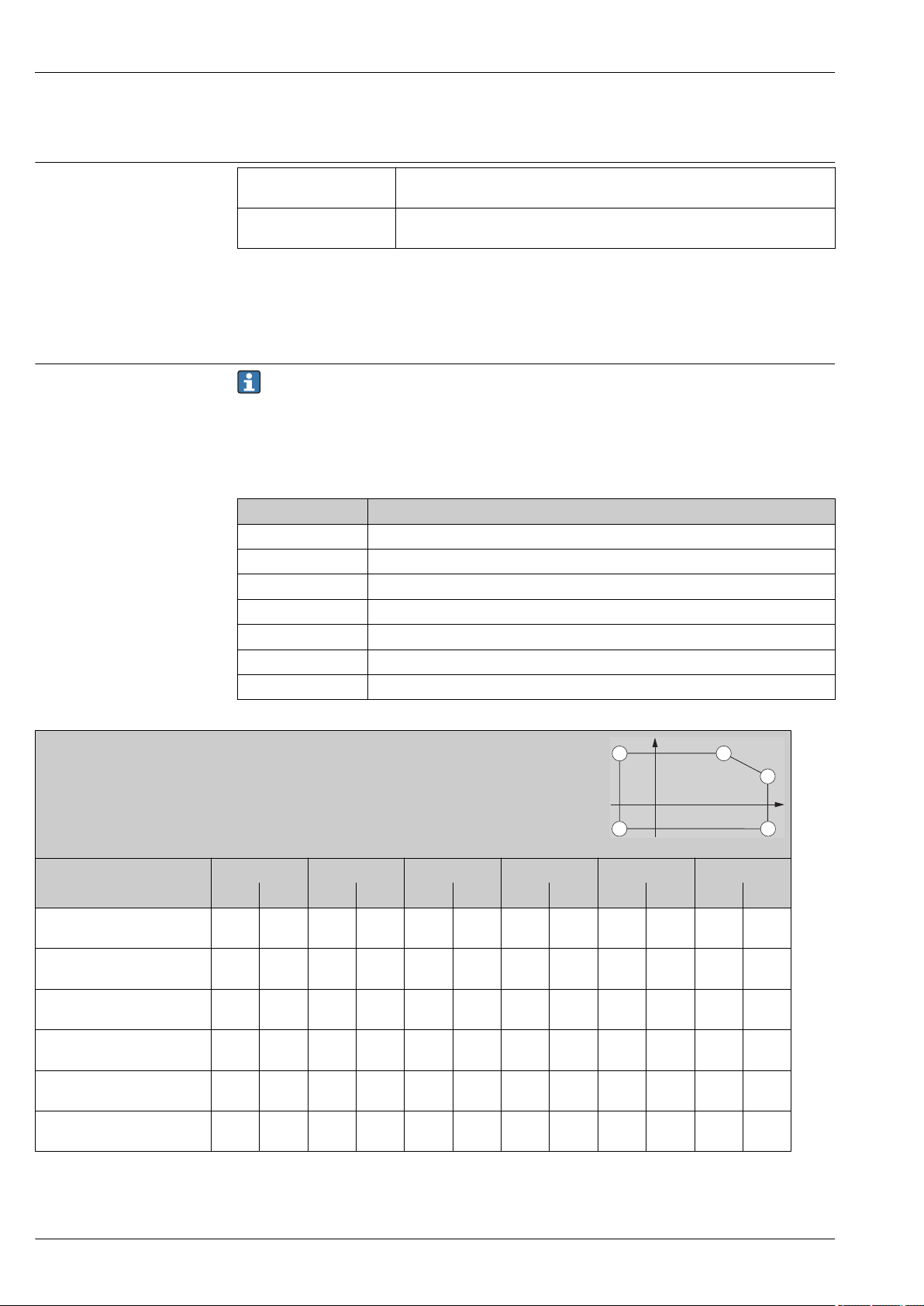
Environment
T
p
P5
P4
P3
P2
P1
T
a
Micropilot FMR51, FMR52
Ambient temperature range
Ambient temperature limits
Measuring device –40 to +80 °C (–40 to +176 °F); –50 °C (–58 °F) with manufacturer declaration on
request
Local display –20 to +70 °C (–4 to +158 °F), the readability of the display may be impaired at
temperatures outside the temperature range.
When operating the device in the open with strong sunlight:
• Mount the device in a shady position.
• Avoid direct sunlight, especially in warmer regions.
• Use a weather protection cover (see accessories).
The following diagrams take into account only functional aspects. There may be further
restrictions for certified device versions. Please refere to the separate Safety Instructions
→ 110.
With a temperature (Tp) at the process connection the admissible ambient temperature (Ta) is
reduced according to the following diagram (temperature derating):
Information concerning the derating tables
Option Meaning
A 2-wire; 4-20 mA HART
B 2-wire; 4-20 mA HART, switch output
C 2-wire; 4-20 mA HART, 4-20 mA
E 2-wire; FF, switch output
G 2-wire; PA, switch output
K 4-wire 90-253VAC; 4-20 mA HART
L 4-wire 10, 4-48VDC; 4-20 mA HART
FMR51
Seal:
• Viton GLT, –40 to 150 °C (–40 to 302 °F)
• Kalrez, –20 to 150 °C (–4 to 302 °F)
Housing: GT18 (316 L)
Temperature unit: °C (°F)
Power Supply; Output (Pos. 2
of the product structure)
P1 P2 P3 P4 P5 P6
T
p
A -40
(-40)81(178)81(178)81(178)
B
Switch output not used
B
Switch output used
C
Channel 2 not used
C
Channel 2 used
E, G
Switch output not used
-40
(-40)82(180)82(180)82(180)
-40
(-40)77(171)77(171)77(171)
-40
(-40)82(180)82(180)82(180)
-40
(-40)79(174)79(174)79(174)
-40
(-40)83(181)83(181)83(181)
A0019351
T
T
a
T
p
a
(302)66(151)
(302)67(153)
(302)61(142)
(302)67(153)
(302)63(145)
(302)68(154)
T
150
150
150
150
150
150
T
p
T
a
150
(302)
150
(302)
150
(302)
150
(302)
150
(302)
150
(302)
T
p
-40
(-40)
-40
(-40)
-40
(-40)
-40
(-40)
-40
(-40)
-40
(-40)
T
a
-40
(-40)
-40
(-40)
-40
(-40)
-40
(-40)
-40
(-40)
-40
(-40)
T
p
-40
T
a
T
p
a
- -
(-40)
-40
- -
(-40)
-40
- -
(-40)
-40
- -
(-40)
-40
- -
(-40)
-40
- -
(-40)
50 Endress+Hauser
Page 51
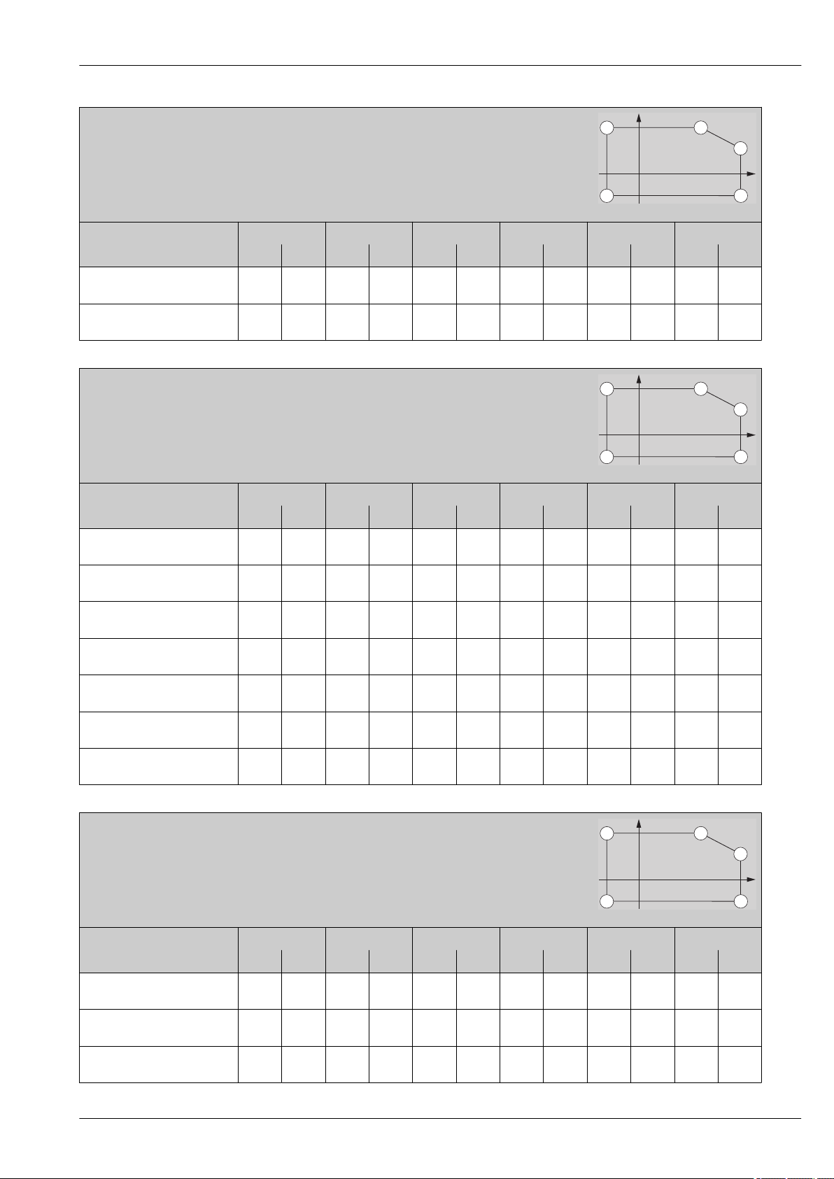
Micropilot FMR51, FMR52
T
p
P5
P4
P3
P2
P1
T
a
T
p
P5
P4
P3
P2
P1
T
a
T
p
P5
P4
P3
P2
P1
T
a
FMR51
Seal:
• Viton GLT, –40 to 150 °C (–40 to 302 °F)
• Kalrez, –20 to 150 °C (–4 to 302 °F)
Housing: GT18 (316 L)
Temperature unit: °C (°F)
Power Supply; Output (Pos. 2
of the product structure)
E, G
Switch output used
K, L -40
FMR51
Seal:
• Viton GLT, –40 to 150 °C (–40 to 302 °F)
• Kalrez, –20 to 150 °C (–4 to 302 °F)
Housing: GT19 (Plastics PBT)
Temperature unit: °C (°F)
Power Supply; Output (Pos. 2
of the product structure)
A -40
B
Switch output not used
B
Switch output used
C
Channel 2 not used
C
Channel 2 used
E, G
Switch output not used
E, G
Switch output used
P1 P2 P3 P4 P5 P6
T
p
-40
(-40)78(172)78(172)78(172)
(-40)77(171)77(171)77(171)
P1 P2 P3 P4 P5 P6
T
p
(-40)80(176)80(176)80(176)
-40
(-40)76(169)76(169)76(169)
-40
(-40)60(140)60(140)60(140)
-40
(-40)82(180)82(180)82(180)
-40
(-40)74(165)74(165)74(165)
-40
(-40)79(174)79(174)79(174)
-40
(-40)63(145)63(145)63(145)
A0019351
T
T
T
a
T
a
T
p
T
p
a
(302)63(145)
(302)62(144)
a
(302)56(133)
(302)56(133)
(302)38(100)
(302)56(133)
(302)55(131)
(302)56(133)
(302)41(106)
T
150
150
T
150
150
150
150
150
150
150
T
p
T
p
T
a
150
(302)
150
(302)
T
a
150
(302)
150
(302)
150
(302)
150
(302)
150
(302)
150
(302)
150
(302)
T
p
-40
(-40)
-40
(-40)
T
p
-40
(-40)
-40
(-40)
-40
(-40)
-40
(-40)
-40
(-40)
-40
(-40)
-40
(-40)
T
a
-40
(-40)
-40
(-40)
T
a
-40
(-40)
-40
(-40)
-40
(-40)
-40
(-40)
-40
(-40)
-40
(-40)
-40
(-40)
T
p
-40
T
a
T
p
a
- -
(-40)
-40
- -
(-40)
A0019351
T
p
-40
T
a
T
p
a
- -
(-40)
-40
- -
(-40)
-40
- -
(-40)
-40
- -
(-40)
-40
- -
(-40)
-40
- -
(-40)
-40
- -
(-40)
FMR51
Seal:
• Viton GLT, –40 to 150 °C (–40 to 302 °F)
• Kalrez, –20 to 150 °C (–4 to 302 °F)
Housing: GT20 (Alu, coated)
Temperature unit: °C (°F)
A0019351
Power Supply; Output (Pos. 2
of the product structure)
A -40
B
Switch output not used
B
Switch output used
P1 P2 P3 P4 P5 P6
T
(-40)81(178)81(178)81(178)
-40
(-40)82(180)82(180)82(180)
-40
(-40)77(171)77(171)77(171)
T
p
T
a
T
p
a
(302)69(156)
(302)70(158)
(302)64(147)
T
150
150
150
T
p
T
a
150
(302)
150
(302)
150
(302)
T
p
-40
(-40)
-40
(-40)
-40
(-40)
T
a
-40
(-40)
-40
(-40)
-40
(-40)
T
p
a
-40
(-40)
-40
(-40)
-40
(-40)
T
p
- -
- -
- -
T
a
Endress+Hauser 51
Page 52
FMR51
T
p
P5
P4
P3
P2
P1
T
a
T
p
P5
P4
P3
P2
P1
T
a
Seal:
• Viton GLT, –40 to 150 °C (–40 to 302 °F)
• Kalrez, –20 to 150 °C (–4 to 302 °F)
Housing: GT20 (Alu, coated)
Temperature unit: °C (°F)
Power Supply; Output (Pos. 2
of the product structure)
C
Channel 2 not used
C
Channel 2 used
E, G
Switch output not used
E, G
Switch output used
P1 P2 P3 P4 P5 P6
T
p
-40
(-40)82(180)82(180)82(180)
-40
(-40)79(174)79(174)79(174)
-40
(-40)83(181)83(181)83(181)
-40
(-40)78(172)78(172)78(172)
K, L -40
(-40)77(171)77(171)77(171)
Micropilot FMR51, FMR52
A0019351
T
T
a
T
p
a
(302)70(158)
(302)66(151)
(302)71(160)
(302)65(149)
(302)65(149)
T
150
150
150
150
150
T
p
T
a
150
(302)
150
(302)
150
(302)
150
(302)
150
(302)
T
p
-40
(-40)
-40
(-40)
-40
(-40)
-40
(-40)
-40
(-40)
T
a
-40
(-40)
-40
(-40)
-40
(-40)
-40
(-40)
-40
(-40)
T
p
-40
T
a
T
p
a
- -
(-40)
-40
- -
(-40)
-40
- -
(-40)
-40
- -
(-40)
-40
- -
(-40)
FMR51
Seal: Graphite, –40 to 250 °C (–40 to 482 °F)
Housing: GT18 (316 L)
Temperature unit: °C (°F)
Power Supply; Output (Pos. 2
of the product structure)
P1 P2 P3 P4 P5 P6
T
p
A -40
(-40)81(178)81(178)81(178)
B
Switch output not used
B
Switch output used
C
Channel 2 not used
C
Channel 2 used
E, G
Switch output not used
E, G
Switch output used
-40
(-40)82(180)82(180)82(180)
-40
(-40)77(171)77(171)77(171)
-40
(-40)82(180)82(180)82(180)
-40
(-40)79(174)79(174)79(174)
-40
(-40)83(181)83(181)83(181)
-40
(-40)78(172)78(172)78(172)
K, L -40
(-40)77(171)77(171)77(171)
A0019351
T
T
a
T
p
a
(482)63(145)
(482)64(147)
(482)58(136)
(482)64(147)
(482)61(142)
(482)65(149)
(482)60(140)
(482)59(138)
T
250
250
250
250
250
250
250
250
T
p
T
a
250
(482)
250
(482)
250
(482)
250
(482)
250
(482)
250
(482)
250
(482)
250
(482)
T
p
-40
(-40)
-40
(-40)
-40
(-40)
-40
(-40)
-40
(-40)
-40
(-40)
-40
(-40)
-40
(-40)
T
a
-40
(-40)
-40
(-40)
-40
(-40)
-40
(-40)
-40
(-40)
-40
(-40)
-40
(-40)
-40
(-40)
T
p
-40
T
a
T
p
a
- -
(-40)
-40
- -
(-40)
-40
- -
(-40)
-40
- -
(-40)
-40
- -
(-40)
-40
- -
(-40)
-40
- -
(-40)
-40
- -
(-40)
52 Endress+Hauser
Page 53
Micropilot FMR51, FMR52
T
p
P5
P4
P3
P2
P1
T
a
T
p
P5
P4
P3
P2
P1
T
a
FMR51
Seal: Graphite, –40 to 250 °C (–40 to 482 °F)
Housing: GT19 (Plastics PBT)
Temperature unit: °C (°F)
Power Supply; Output (Pos. 2
of the product structure)
A -40
B
Switch output not used
B
Switch output used
C
Channel 2 not used
C
Channel 2 used
E, G
Switch output not used
E, G
Switch output used
P1 P2 P3 P4 P5 P6
T
p
(-40)80(176)80(176)80(176)
-40
(-40)76(169)76(169)76(169)
-40
(-40)60(140)60(140)60(140)
-40
(-40)82(180)82(180)82(180)
-40
(-40)74(165)74(165)74(165)
-40
(-40)79(174)79(174)79(174)
-40
(-40)63(145)63(145)63(145)
A0019351
T
T
a
T
p
a
(482)44(111)
(482)44(111)
(482)32(90)
(482)44(111)
(482)44(111)
(482)44(111)
(482)35(95)
T
250
250
250
250
250
250
250
T
p
T
a
250
(482)
250
(482)
250
(482)
250
(482)
250
(482)
250
(482)
250
(482)
T
p
-40
(-40)
-40
(-40)
-40
(-40)
-40
(-40)
-40
(-40)
-40
(-40)
-40
(-40)
T
a
-40
(-40)
-40
(-40)
-40
(-40)
-40
(-40)
-40
(-40)
-40
(-40)
-40
(-40)
T
p
-40
T
a
T
p
a
- -
(-40)
-40
- -
(-40)
-40
- -
(-40)
-40
- -
(-40)
-40
- -
(-40)
-40
- -
(-40)
-40
- -
(-40)
FMR51
Seal: Graphite, –40 to 250 °C (–40 to 482 °F)
Housing: GT20 (Alu, coated)
Temperature unit: °C (°F)
Power Supply; Output (Pos. 2
of the product structure)
P1 P2 P3 P4 P5 P6
T
p
A -40
(-40)81(178)81(178)81(178)
B
Switch output not used
B
Switch output used
C
Channel 2 not used
C
Channel 2 used
E, G
Switch output not used
E, G
Switch output used
-40
(-40)82(180)82(180)82(180)
-40
(-40)77(171)77(171)77(171)
-40
(-40)82(180)82(180)82(180)
-40
(-40)79(174)79(174)79(174)
-40
(-40)83(181)83(181)83(181)
-40
(-40)78(172)78(172)78(172)
K, L -40
(-40)77(171)77(171)77(171)
A0019351
T
T
a
T
p
a
(482)67(153)
(482)68(154)
(482)62(144)
(482)68(154)
(482)64(147)
(482)69(156)
(482)64(147)
(482)63(154)
T
250
250
250
250
250
250
250
250
T
p
T
a
250
(482)
250
(482)
250
(482)
250
(482)
250
(482)
250
(482)
250
(482)
250
(482)
T
p
-40
(-40)
-40
(-40)
-40
(-40)
-40
(-40)
-40
(-40)
-40
(-40)
-40
(-40)
-40
(-40)
T
a
-40
(-40)
-40
(-40)
-40
(-40)
-40
(-40)
-40
(-40)
-40
(-40)
-40
(-40)
-40
(-40)
T
p
-40
T
a
T
p
a
- -
(-40)
-40
- -
(-40)
-40
- -
(-40)
-40
- -
(-40)
-40
- -
(-40)
-40
- -
(-40)
-40
- -
(-40)
-40
- -
(-40)
Endress+Hauser 53
Page 54
FMR51
T
p
P6
P5
P4
P3
P2
P1
T
a
T
p
P6
P5
P4
P3
P2
P1
T
a
Seal: Graphite, –196 to 450 °C (–321 to 842 °F)
Housing: GT18 (316 L)
Temperature unit: °C (°F)
Power Supply; Output (Pos. 2
of the product structure)
P1 P2 P3 P4 P5 P6
T
T
p
A -196
(-321)81(178)81(178)81(178)
B
Switch output not used
B
Switch output used
C
Channel 2 not used
C
Channel 2 used
E, G
Switch output not used
E, G
Switch output used
-196
(-321)82(180)82(180)82(180)
-196
(-321)77(171)77(171)77(171)
-196
(-321)82(180)82(180)82(180)
-196
(-321)79(174)79(174)79(174)
-196
(-321)83(181)83(181)83(181)
-196
(-321)78(172)78(172)78(172)
K, L -196
(-321)77(171)77(171)77(171)
Micropilot FMR51, FMR52
A0019344
T
a
T
p
a
(842)26(79)
(842)26(79)
(842)25(77)
(842)26(79)
(842)26(79)
(842)26(79)
(842)26(79)
(842)26(79)
T
450
450
450
450
450
450
450
450
T
p
T
a
450
(842)
450
(842)
450
(842)
450
(842)
450
(842)
450
(842)
450
(842)
450
(842)
T
p
-40
(-40)
-40
(-40)
-40
(-40)
-40
(-40)
-40
(-40)
-40
(-40)
-40
(-40)
-40
(-40)
T
a
-40
(-40)
-40
(-40)
-40
(-40)
-40
(-40)
-40
(-40)
-40
(-40)
-40
(-40)
-40
(-40)
T
p
-40
(-40)
-40
(-40)
-40
(-40)
-40
(-40)
-40
(-40)
-40
(-40)
-40
(-40)
-40
(-40)
T
a
-196
(-321)
-196
(-321)
-196
(-321)
-196
(-321)
-196
(-321)
-196
(-321)
-196
(-321)
-196
(-321)
T
p
a
-15
(+5)
-15
(+5)
-15
(+5)
-15
(+5)
-15
(+5)
-15
(+5)
-15
(+5)
-15
(+5)
FMR51
Seal: Graphite, –196 to 450 °C (–321 to 842 °F)
Housing: GT19 (Plastics PBT)
Temperature unit: °C (°F)
Power Supply; Output (Pos. 2
of the product structure)
P1 P2 P3 P4 P5 P6
T
T
p
A -196
(-321)80(176)80(176)80(176)
B
Switch output not used
B
Switch output used
C
Channel 2 not used
C
Channel 2 used
E, G
Switch output not used
E, G
Switch output used
-196
(-321)76(169)76(169)76(169)
-196
(-321)60(140)60(140)60(140)
-196
(-321)82(180)82(180)82(180)
-196
(-321)74(165)74(165)74(165)
-196
(-321)79(174)79(174)79(174)
-196
(-321)63(145)63(145)63(145)
A0019344
T
a
T
p
T
a
450
(842)
450
(842)
450
(842)
450
(842)
450
(842)
450
(842)
450
(842)
T
p
-29
(-20)
-29
(-20)
-29
(-20)
-29
(-20)
-29
(-20)
-29
(-20)
-29
(-20)
T
a
450
(842)
450
(842)
450
(842)
450
(842)
450
(842)
450
(842)
450
(842)
T
p
-40
(-40)
-40
(-40)
-40
(-40)
-40
(-40)
-40
(-40)
-40
(-40)
-40
(-40)
T
a
-40
(-40)
-40
(-40)
-40
(-40)
-40
(-40)
-40
(-40)
-40
(-40)
-40
(-40)
T
p
-40
(-40)
-40
(-40)
-40
(-40)
-40
(-40)
-40
(-40)
-40
(-40)
-40
(-40)
a
-196
(-321)9(48)
-196
(-321)9(48)
-196
(-321)9(48)
-196
(-321)9(48)
-196
(-321)9(48)
-196
(-321)9(48)
-196
(-321)9(48)
T
T
p
a
54 Endress+Hauser
Page 55
Micropilot FMR51, FMR52
T
p
P6
P5
P4
P3
P2
P1
T
a
T
p
P5
P4
P3
P2
P1
T
a
FMR51
Seal: Graphite, –196 to 450 °C (–321 to 842 °F)
Housing: GT20 (Alu, coated)
Temperature unit: °C (°F)
Power Supply; Output (Pos. 2
of the product structure)
A -196
B
Switch output not used
B
Switch output used
C
Channel 2 not used
C
Channel 2 used
E, G
Switch output not used
E, G
Switch output used
K, L -196
P1 P2 P3 P4 P5 P6
T
p
(-321)81(178)81(178)81(178)
-196
(-321)82(180)82(180)82(180)
-196
(-321)77(171)77(171)77(171)
-196
(-321)82(180)82(180)82(180)
-196
(-321)79(174)79(174)79(174)
-196
(-321)83(181)83(181)83(181)
-196
(-321)78(172)78(172)78(172)
(-321)77(17177(171)77(171)
A0019344
T
T
a
T
p
a
(842)39(102)
(842)39(102)
(842)36(97)
(842)39(102)
(842)38(100)
(842)39(102)
(842)38(100)
(842)37(99)
T
450
450
450
450
450
450
450
450
T
p
T
a
450
(842)
450
(842)
450
(842)
450
(842)
450
(842)
450
(842)
450
(842)
450
(842)
T
p
-40
(-40)
-40
(-40)
-40
(-40)
-40
(-40)
-40
(-40)
-40
(-40)
-40
(-40)
-40
(-40)
T
a
-40
(-40)
-40
(-40)
-40
(-40)
-40
(-40)
-40
(-40)
-40
(-40)
-40
(-40)
-40
(-40)
T
p
-40
(-40)
-40
(-40)
-40
(-40)
-40
(-40)
-40
(-40)
-40
(-40)
-40
(-40)
-40
(-40)
T
a
-196
(-321)
-196
(-321)
-196
(-321)
-196
(-321)
-196
(-321)
-196
(-321)
-196
(-321)
-196
(-321)
T
p
a
-20
(-4)
-20
(-4)
-20
(-4)
-20
(-4)
-20
(-4)
-20
(-4)
-20
(-4)
-20
(-4)
FMR52
Antenna: Horn 50mm/2"
Housing: GT18 (316 L)
Temperature unit: °C (°F)
Power Supply; Output (Pos. 2
of the product structure)
T
A -40
(-40)81(178)81(178)81(178)
B
Switch output not used
B
Switch output used
C
Channel 2 not used
C
Channel 2 used
E, G
Switch output not used
E, G
Switch output used
-40
(-40)82(180)82(180)82(180)
-40
(-40)77(171)77(171)77(171)
-40
(-40)82(180)82(180)82(180)
-40
(-40)79(174)79(174)79(174)
-40
(-40)83(181)83(181)83(181)
-40
(-40)78(172)78(172)78(172)
K, L -40
(-40)77(171)77(171)77(171)
P1 P2 P3 P4 P5 P6
T
p
T
a
T
p
a
(392)61(142)
(392)61(142)
(392)55(131)
(392)62(144)
(392)58(136)
(392)62(144)
(392)57(135)
(392)56(133)
T
200
200
200
200
200
200
200
200
T
p
T
a
200
(392)
200
(392)
200
(392)
200
(392)
200
(392)
200
(392)
200
(392)
200
(392)
T
p
-40
(-40)
-40
(-40)
-40
(-40)
-40
(-40)
-40
(-40)
-40
(-40)
-40
(-40)
-40
(-40)
T
a
-40
(-40)
-40
(-40)
-40
(-40)
-40
(-40)
-40
(-40)
-40
(-40)
-40
(-40)
-40
(-40)
T
p
a
-40
(-40)
-40
(-40)
-40
(-40)
-40
(-40)
-40
(-40)
-40
(-40)
-40
(-40)
-40
(-40)
T
p
- -
- -
- -
- -
- -
- -
- -
- -
A0019351
T
a
Endress+Hauser 55
Page 56
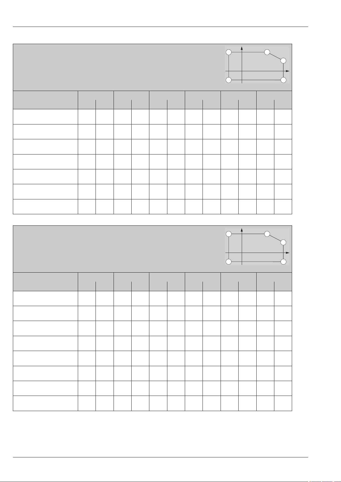
FMR52
T
p
P5
P4
P3
P2
P1
T
a
T
p
P5
P4
P3
P2
P1
T
a
Antenna: Horn 50mm/2"
Housing: GT19 (Plastics PBT)
Temperature unit: °C (°F)
Power Supply; Output (Pos. 2
of the product structure)
T
A -40
(-40)80(176)80(176)80(176)
B
Switch output not used
B
Switch output used
C
Channel 2 not used
C
Channel 2 used
E, G
Switch output not used
E, G
Switch output used
-40
(-40)76(169)76(169)76(169)
-40
(-40)60(140)60(140)60(140)
-40
(-40)82(180)82(180)82(180)
-40
(-40)74(165)74(165)74(165)
-40
(-40)79(174)79(174)79(174)
-40
(-40)63(145)63(145)63(145)
Micropilot FMR51, FMR52
P1 P2 P3 P4 P5 P6
T
p
T
a
T
p
a
(392)42(108)
(392)42(108)
(392)31(88)
(392)42(108)
(392)42(108)
(392)42(108)
(392)33(91)
T
200
200
200
200
200
200
200
T
p
T
a
200
(392)
200
(392)
200
(392)
200
(392)
200
(392)
200
(392)
200
(392)
T
p
-40
(-40)
-40
(-40)
-40
(-40)
-40
(-40)
-40
(-40)
-40
(-40)
-40
(-40)
T
a
-40
(-40)
-40
(-40)
-40
(-40)
-40
(-40)
-40
(-40)
-40
(-40)
-40
(-40)
T
p
a
-40
(-40)
-40
(-40)
-40
(-40)
-40
(-40)
-40
(-40)
-40
(-40)
-40
(-40)
T
p
- -
- -
- -
- -
- -
- -
- -
A0019351
T
a
FMR52
Antenna: Horn 50mm/2"
Housing: GT20 (Alu, coated)
Temperature unit: °C (°F)
Power Supply; Output (Pos. 2
of the product structure)
T
A -40
(-40)81(178)81(178)81(178)
B
Switch output not used
B
Switch output used
C
Channel 2 not used
C
Channel 2 used
E, G
Switch output not used
E, G
Switch output used
-40
(-40)82(180)82(180)82(180)
-40
(-40)77(171)77(171)77(171)
-40
(-40)82(180)82(180)82(180)
-40
(-40)79(174)79(174)79(174)
-40
(-40)83(181)83(181)83(181)
-40
(-40)78(172)78(172)78(172)
K, L -40
(-40)77(171)77(171)77(171)
P1 P2 P3 P4 P5 P6
T
p
T
a
T
p
a
200
(392)65(149)
200
(392)65(149
200
(392)59(138)
200
(392)66(151)
200
(392)62(144)
200
(392)66(1512)
200
(392)61(142)
200
(392)60(140)
T
T
p
T
a
200
(392)
200
(392)
200
(392)
200
(392)
200
(392)
200
(392)
200
(392)
200
(392)
T
p
-40
(-40)
-40
(-40)
-40
(-40)
-40
(-40)
-40
(-40)
-40
(-40)
-40
(-40)
-40
(-40)
T
a
-40
(-40)
-40
(-40)
-40
(-40)
-40
(-40)
-40
(-40)
-40
(-40)
-40
(-40)
-40
(-40)
T
p
a
-40
(-40)
-40
(-40)
-40
(-40)
-40
(-40)
-40
(-40)
-40
(-40)
-40
(-40)
-40
(-40)
T
p
- -
- -
- -
- -
- -
- -
- -
- -
A0019351
T
a
56 Endress+Hauser
Page 57
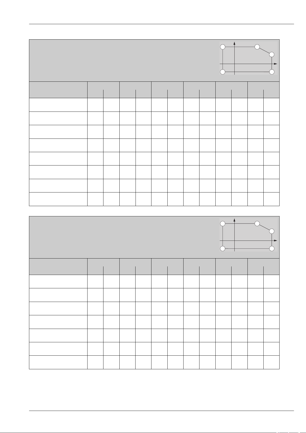
Micropilot FMR51, FMR52
T
p
P5
P4
P3
P2
P1
T
a
T
p
P5
P4
P3
P2
P1
T
a
FMR52
Antenna: Horn 80mm/2"
Housing: GT18 (316 L)
Temperature unit: °C (°F)
Power Supply; Output (Pos. 2
of the product structure)
A -40
(-40)81(178)81(178)81(178)
B
Switch output not used
B
Switch output used
C
Channel 2 not used
C
Channel 2 used
E, G
Switch output not used
E, G
Switch output used
K, L -40
(-40)82(180)82(180)82(180)
(-40)77(171)77(171)77(171)
(-40)82(180)82(180)82(180)
(-40)79(174)79(174)79(174)
(-40)83(181)83(181)83(181)
(-40)78(172)78(172)78(172)
(-40)77(171)77(171)77(171)
P1 P2 P3 P4 P5 P6
T
-40
-40
-40
-40
-40
-40
T
p
T
a
T
p
a
(392)57(135)
(392)57(135)
(392)51(124)
(392)57(135)
(392)54(129)
(392)57(135)
(392)53(127)
(392)52(126)
T
200
200
200
200
200
200
200
200
T
p
T
a
200
(392)
200
(392)
200
(392)
200
(392)
200
(392)
200
(392)
200
(392)
200
(392)
T
p
-40
(-40)
-40
(-40)
-40
(-40)
-40
(-40)
-40
(-40)
-40
(-40)
-40
(-40)
-40
(-40)
T
a
-40
(-40)
-40
(-40)
-40
(-40)
-40
(-40)
-40
(-40)
-40
(-40)
-40
(-40)
-40
(-40)
T
p
a
-40
(-40)
-40
(-40)
-40
(-40)
-40
(-40)
-40
(-40)
-40
(-40)
-40
(-40)
-40
(-40)
T
p
- -
- -
- -
- -
- -
- -
- -
- -
A0019351
T
a
FMR52
Antenna: Horn 80mm/2"
Housing: GT19 (Plastics PBT)
Temperature unit: °C (°F)
Power Supply; Output (Pos. 2
of the product structure)
T
A -40
(-40)80(176)80(176)80(176)
B
Switch output not used
B
Switch output used
C
Channel 2 not used
C
Channel 2 used
E, G
Switch output not used
E, G
Switch output used
-40
(-40)76(169)76(169)76(169)
-40
(-40)60(140)60(140)60(140)
-40
(-40)82(180)82(180)82(180)
-40
(-40)74(165)74(165)74(165)
-40
(-40)79(174)79(174)79(174)
-40
(-40)63(145)63(145)63(145)
P1 P2 P3 P4 P5 P6
T
p
T
a
T
p
a
(392)36(97)
(392)36(97)
(392)27(81)
(392)36(97)
(392)36(97)
(392)36(97)
(392)30(86)
T
200
200
200
200
200
200
200
T
p
T
a
200
(392)
200
(392)
200
(392)
200
(392)
200
(392)
200
(392)
200
(392)
T
p
-40
(-40)
-40
(-40)
-40
(-40)
-40
(-40)
-40
(-40)
-40
(-40)
-40
(-40)
T
a
-40
(-40)
-40
(-40)
-40
(-40)
-40
(-40)
-40
(-40)
-40
(-40)
-40
(-40)
T
p
a
-40
(-40)
-40
(-40)
-40
(-40)
-40
(-40)
-40
(-40)
-40
(-40)
-40
(-40)
T
p
- -
- -
- -
- -
- -
- -
- -
A0019351
T
a
Endress+Hauser 57
Page 58
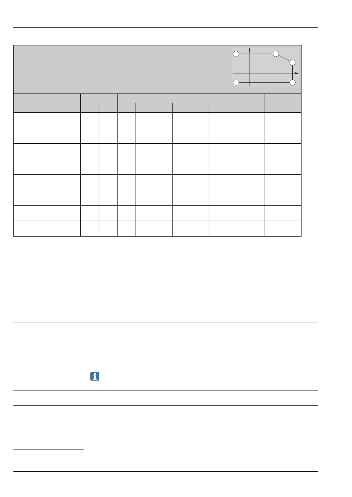
FMR52
T
p
P5
P4
P3
P2
P1
T
a
Antenna: Horn 80mm/2"
Housing: GT20 (Alu, coated)
Temperature unit: °C (°F)
Power Supply; Output (Pos. 2
of the product structure)
T
A -40
(-40)81(178)81(178)81(178)
B
Switch output not used
B
Switch output used
C
Channel 2 not used
C
Channel 2 used
E, G
Switch output not used
E, G
Switch output used
-40
(-40)82(180)82(180)82(180)
-40
(-40)77(171)77(171)77(171)
-40
(-40)82(180)82(180)82(180)
-40
(-40)79(174)79(174)79(174)
-40
(-40)83(181)83(181)83(181)
-40
(-40)78(172)78(172)78(172)
K, L -40
(-40)77(171)77(171)77(171)
Micropilot FMR51, FMR52
P1 P2 P3 P4 P5 P6
T
p
T
a
T
p
a
(392)61(142)
(392)62(144)
(392)56(133)
(392)62(144)
(392)58(136)
(392)62(144)
(392)58(136)
(392)57(135)
T
200
200
200
200
200
200
200
200
T
p
T
a
200
(392)
200
(392)
200
(392)
200
(392)
200
(392)
200
(392)
200
(392)
200
(392)
T
p
-40
(-40)
-40
(-40)
-40
(-40)
-40
(-40)
-40
(-40)
-40
(-40)
-40
(-40)
-40
(-40)
T
a
-40
(-40)
-40
(-40)
-40
(-40)
-40
(-40)
-40
(-40)
-40
(-40)
-40
(-40)
-40
(-40)
T
p
a
-40
(-40)
-40
(-40)
-40
(-40)
-40
(-40)
-40
(-40)
-40
(-40)
-40
(-40)
-40
(-40)
T
p
- -
- -
- -
- -
- -
- -
- -
- -
A0019351
T
a
Storage temperature
Climate class
Altitude according to IEC61010-1 Ed.3
Degree of protection
Vibration resistance
Cleaning the antenna
–40 to +80 °C (–40 to +176 °F)
–50 °C (–58 °F) with manufacturer declaration on request
DIN EN 60068-2-38 (test Z/AD)
• Generally up to 2 000 m (6 600 ft) above MSL.
• Above 2 000 m (6 600 ft) if the following conditions are met:
– Ordering feature 020 "Power supply; Output" = A, B, C, E or G (2-wire versions)
– Supply voltage U < 35 V
– Supply voltage of overvoltage category 1
• With closed housing tested according to:
– IP68, NEMA6P (24 h at 1.83 m under water surface)
– For plastic housing with transparent cover (display module): IP68 (24 h at 1.00 m under water
surface)
6)
– IP66, NEMA4X
• With open housing: IP20, NEMA1
• Display module: IP22, NEMA2
Degree of protection IP68 NEMA6P applies for M12 PROFIBUS PA plugs only when the
PROFIBUS cable is plugged in and is also rated IP68 NEMA6P.
DIN EN 60068-2-64 / IEC 60068-2-64: 20 to 2 000 Hz, 1 (m/s2)2/Hz
The antenna can get contaminated, depending on the application. The emission and reception of
microwaves can thus eventually be hindered. The degree of contamination leading to an error
depends on the medium and the reflectivity, mainly determined by the dielectric constant εr.
If the medium tends to cause contamination and deposits, cleaning on a regular basis is
recommended. Care has to be taken not to damage the antenna in the process of a mechanical or
6) This restriction is valid if the following options of the product structure have been selected at the same time: 030 ("Display, Operation") = C
("SD02") or E ("SD03"); 040 ("Housing") = A ("GT19").
58 Endress+Hauser
Page 59

Micropilot FMR51, FMR52
hose-down cleaning. The material compatibility has to be considered if cleaning agents are used! The
maximum permitted temperature at the flange should not be exceeded.
Electromagnetic compatibility (EMC)
Electromagnetic compatibility to all relevant requirements of the EN 61326- series and NAMUR
recommendation EMC (NE21). For details see declaration of conformity.
7)
.
If only the analogue signal is used, unshielded interconnection lines are sufficient for the
installation. In case of using the digital signal (HART/ PA/ FF) use shielded interconnection lines.
Max. fluctuations during EMC- tests: < 0.5 % of the span. As an exception to this, the maximum
fluctuations may amount to 2 % of the span for devices with plastic housing and see-through lid
(integrated display SD02 or SD03) if strong electromagnetic interferences in the frequenency range
of 1 to 2 GHz are present.
7) Can be downloaded from www.endress.com.
Endress+Hauser 59
Page 60
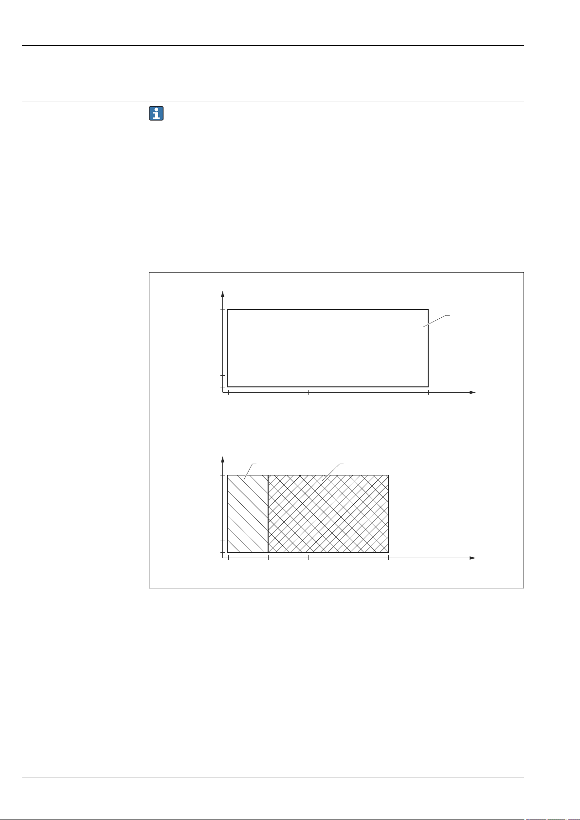
Process
p
p
-40
(-40)
-40
(-40)
-20
(-4)
+150
(+302)
+250
(+482)
0
(+32)
0
(+32)
T
p
[°C]
([°F])
T
p
[°C]
([°F])
1
2
3
[bar] ([psi])
[bar] ([psi])
40 (580)
40 (580)
-1 (-14.5)
-1 (-14.5)
0 (0)
0 (0)
Micropilot FMR51, FMR52
Process temperature, Process pressure
The specified pressure range may be reduced due to the selected process connection. The
pressure rating (PN) specified on the flanges refers to a reference temperature of 20 °C, for
ASME flanges 100 °F. Pay attention to pressure-temperature dependencies.
Please refer to the following standards for the pressure values permitted for higher
temperatures:
• EN 1092-1: 2001 Tab. 18
With regard to their temperature stability properties, the materials 1.4435 and 1.4404 are
grouped under 13E0 in EN 1092-1 Tab. 18. The chemical composition of the two materials
can be identical.
• ASME B 16.5a - 1998 Tab. 2-2.2 F316
• ASME B 16.5a - 1998 Tab. 2.3.8 N10276
• JIS B 2220
FMR51
17 FMR51: Admissible range of process temperature and process pressure
1 Seal: Graphite (Feature 090 "Seal", Option D3)
2 Seal: Viton (Feature 090 "Seal", Option A5)
3 Seal: Kalrez (Feature 090 "Seal", Option C1)
60 Endress+Hauser
A0022656-EN
Page 61
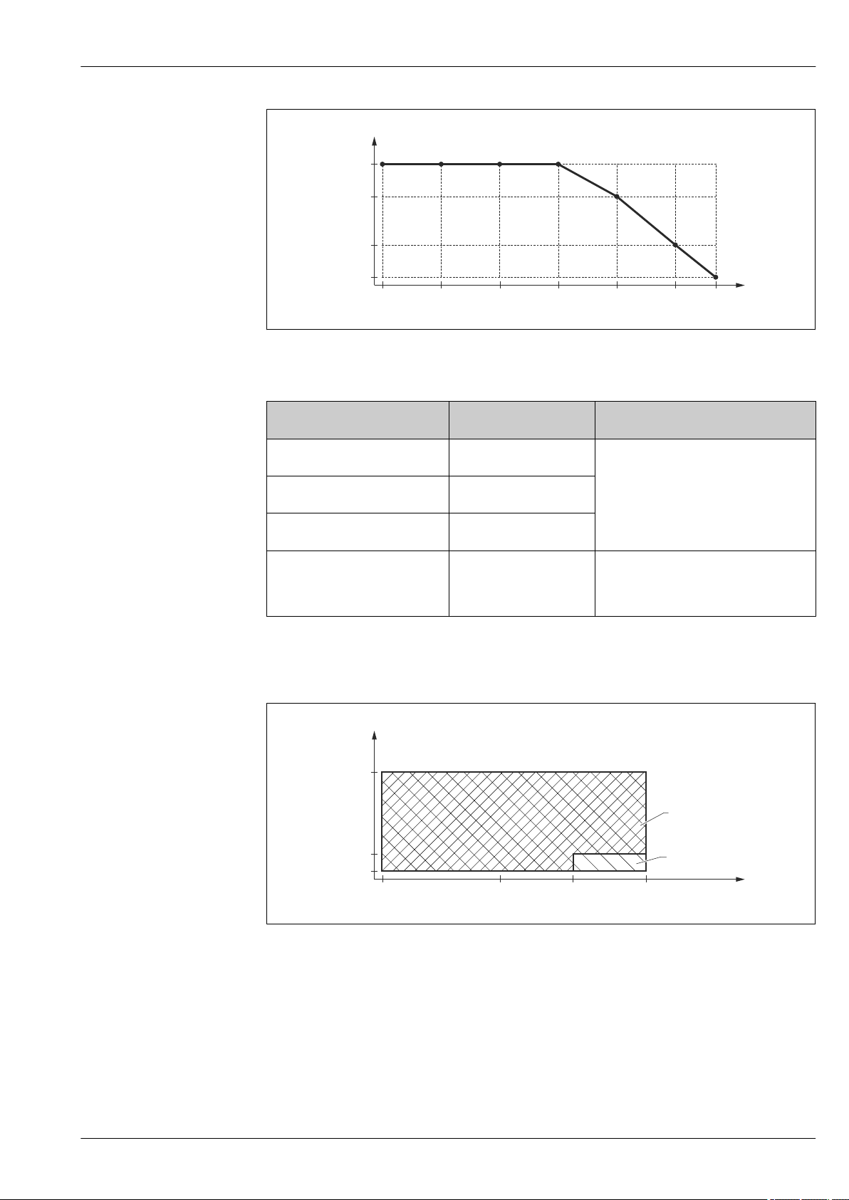
Micropilot FMR51, FMR52
p
-196
(-321)
-100
(-148)
+310
(+590)
+350
(+662)
+400
(+752)
+450
(+842)
0
(+32)
T
p
[°C]
([°F])
160 (2320)
154 (2233)
148 (2146)
142 (2059)
[bar] ([psi])
p
-40
(-40)
0
(+32)
T
p
[°C]
([°F])
+200
(+392)
+100
(+212)
2
1
[bar] ([psi])
25 (362.5)
-1 (-14.5)
0 (0)
A0020555-EN
18 FMR51: Admissible range of process temperature and process pressure of the HT version (Feature 090
"Seal", Option D2)
Feature 090 "Seal" Admissible process
temperature
A5: Viton GLT –40 to +150 °C
(–40 to 302 °F)
C1: Kalrez –20 to +150 °C
(–4 to 302 °F)
D3: Graphite,
40...250°C/-40...482°F
D2: Graphite,
196...450°C/-321...842°F (HT)
1) For devices with CRN approval the pressure range may be reduced → 92
–40 to +250 °C
(–40 to 482 °F)
–196 to +450 °C
(–321 to 842 °F)
Admissible process pressure
p
= –1 to 40 bar (–14.5 to 580 psi)
rel
p
= –1 to 160 bar (–14.5 to 2 320 psi)
rel
Observe the temperature-dependent
restrictions indicated in the diagram
1)
above
.
FMR52
19 FMR52: Admissible range of process temperature and process pressure
1 Valid for the following process connections: 6" (ANSI), DN150 (EN), 10K150A (JIS)
2 Valid for all other types of process connection
Endress+Hauser 61
A0023250-EN
Page 62
Micropilot FMR51, FMR52
Dielectric constant
Feature 100 "Process Connection" Admissible process
temperature
• AFK: 2" 150lbs (ANSI)
• AGK: 3" 150lbs (ANSI)
• AHK: 4" 150lbs (ANSI)
• CFK: DN50 PN10/16 (EN)
• CGK: DN80 PN10/16 (EN)
• CHK: DN100 PN10/16 (EN)
• KFK: 10K 50A (JIS)
• KGK: 10K 80A (JIS)
• KHK: 10K 100A (JIS)
• MRK: DIN11851 DN50
• MTK: DIN11851 DN80
• TDK: Tri-Clamp 2"
• TFK: Tri-Clamp 3"
• THK: Tri-Clamp 4"
• AJK: 6" 150lbs (ANSI)
• CJK: DN150 PN10/16 (EN)
• KJK: 10K 150A (JIS)
1) For devices with CRN approval the pressure range may be reduced → 92
2) Process connections up to 25 bar (363 psi) on request
–40 to +200 °C
(–40 to 392 °F)
Admissible process pressure
p
= –1 to 25 bar (–14.5 to 363 psi)
rel
• For T = –40 to +100 °C (–40 to 212 °F):
p
= –1 to 25 bar (–14.5 to 363 psi)
rel
• For T = 100 to 200 °C (212 to 392 °F):
p
= 0 to 25 bar (0 to 363 psi)
rel
• For liquids
– εr ≥ 1.9 in free-field applications
– εr ≥ 1.4 in stilling well
• For bulk solids
εr ≥ 1.6
For dielectric constants (DC values) of many media commonly used in various industries refer
to:
• the Endress+Hauser DC manual (CP01076F)
• the Endress+Hauser "DC Values App" (available for Android and iOS)
1) 2)
62 Endress+Hauser
Page 63
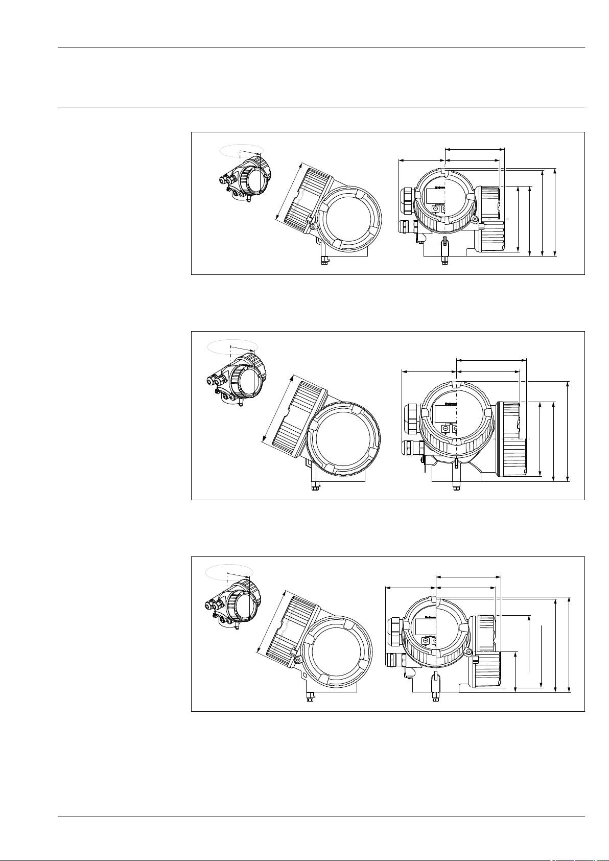
Micropilot FMR51, FMR52
146 (5.75)
142 (5.59)
115.25 (4.54)
ø108.5 (4.27)
78 (3.07) 90 (3.54)
98 (3.86)*
ø103.5 (4.07)
R110
144 (5.67)
113.5 (4.47)
ø106 (4.17)
78 (3.07)
90 (3.54)
99 (3.9)*
ø106 (4.17)
R110
145.5 (5.73)
141.5 (5.57)
ø112 (4.41)
ø108.5 (4.27)
78 (3.07)
90 (3.54)
98 (3.86)*
ø103.5 (4.07)
R110
61 (2.4)
Mechanical construction
Dimensions Dimensions of the electronics housing
20 Housing GT18 (316L); Dimensions in mm (in)
*for devices with integrated overvoltage protection.
A0011666
A0011346
21 Housing GT19 (Plastics PBT); Dimensions in mm (in)
*for devices with integrated overvoltage protection.
A0020751
22 Housing GT20 (Alu coated); Dimensions in mm (in)
*for devices with integrated overvoltage protection.
Endress+Hauser 63
Page 64
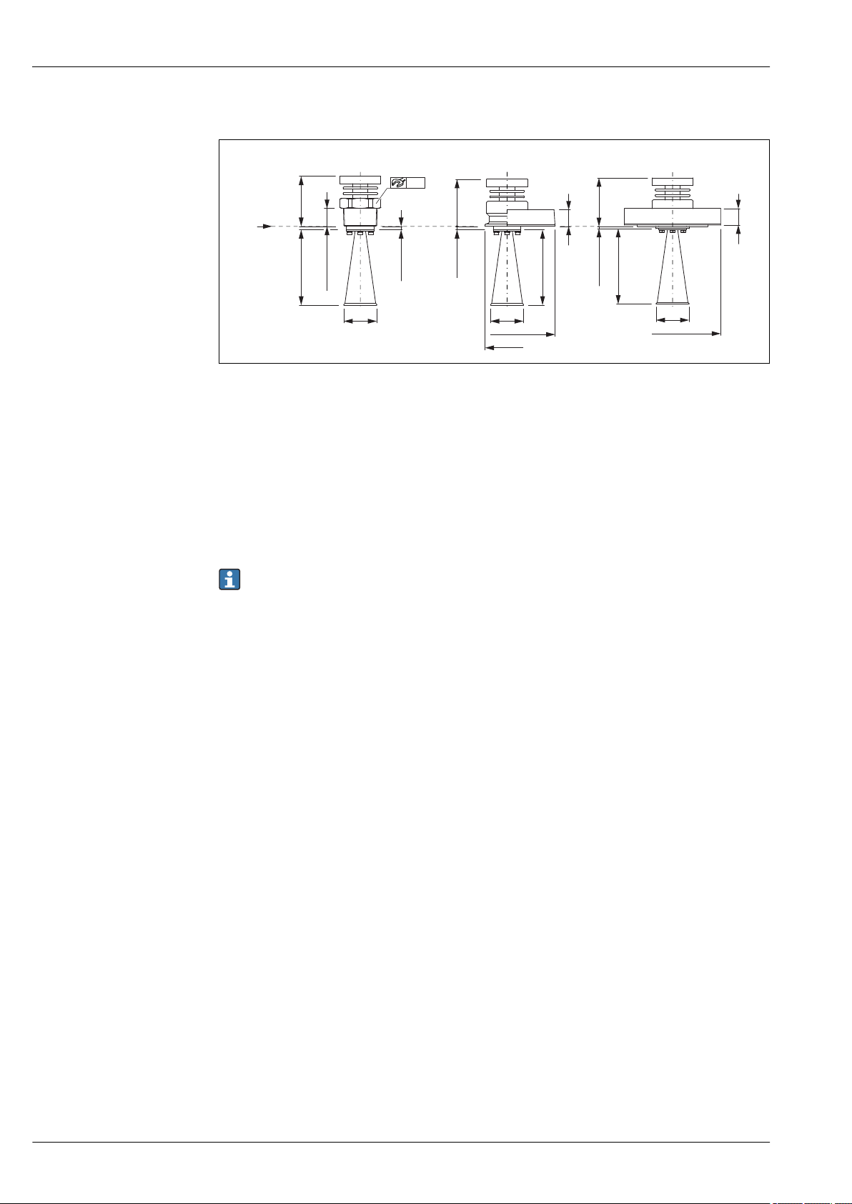
Micropilot FMR51, FMR52
A
B C
R
L
L
68
(2.68)
63
(2.48)
5 (0.2)
26 (1.02)
b
5 (0.2)
ød
55
ød
øD
øA
D
L
65
(2.56)
b
2 (0.08)
ød
øD
FMR51: Version T ≤ 150 °C (302 °F); without antenna extension
23 FMR51: Version T < 150 °C (302 °F); without antenna extension; dimensions: mm (in)
A Process connection: Thread
B Process connection: Tri-Clamp ISO2852
C Process connection: Flange 316L
D Process connection: Flange AlloyC>316L
R Reference point of the measurement
A0023383
Valid for the following device versions
Feature 090 "Seal":
– A5: Viton GLT
– C1: Kalrez
• Dimensions of the horn antenna (L, ⌀d): → 68
• Dimensions of the process connection (⌀A, ⌀D, b): → 68
64 Endress+Hauser
Page 65
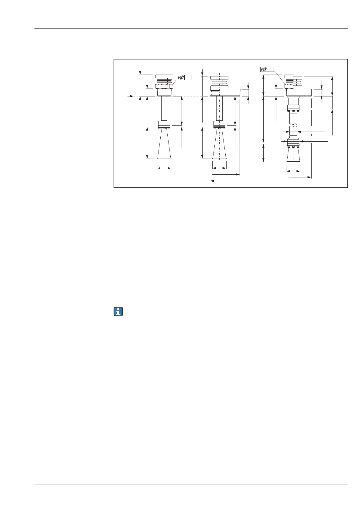
Micropilot FMR51, FMR52
A
R
L
68 (2.68)
26 (1.02)
5 (0.2)
100(3.94)
ød
55
B
C
L
63 (2.48)
b
5 (0.2)
100(3.94)
ød
øD
øA
D E
63
(2.48)
68
(2.68)
b
47 (1.85)
ød
øD
101...1000
(3.98...39.3)
L2
ø27(1.06)
ø42.5(1.7)
55
26 (1.02)
FMR51: Version T ≤ 150 °C (302 °F); with antenna extension
A0023384
24 MR51: Version T < 150 °C (302 °F); with antenna extension; dimensions: mm (in)
A Process connections: Thread; Accessory mounted: 100mm/4" antenna extension
B Prozessanschluss: Tri-Clamp ISO2852; Accessory mounted: 100mm/4" antenna extension
C Process connection: Flange 316L; Accessory mounted: 100mm/4" antenna extension
D Process connection: Thread; Accessory mounted: ..... mm/inch antenna extension
E Process connection: Flange 316L;Accessory mounted: ..... mm/inch antenna extension
R Reference point of the measurement
Valid for the following device versions
• Feature 090 "Seal":
– A5: Viton GLT
– C1: Kalrez
• Feature 610 "Accessory mounted"
– OM: 100mm/4" antenna extension (diagrams A, B, C)
– OU: ..... mm antenna extension (101 ... 1000 mm) (diagrams D, E)
– OV: ..... inch antenna extension (3,98 ... 39,3 in) (diagrams D, E)
• Dimensions of the horn antenna (L, L2, ⌀d): → 68
• Dimensions of the process connections (⌀A, ⌀D, b): → 68
Endress+Hauser 65
Page 66
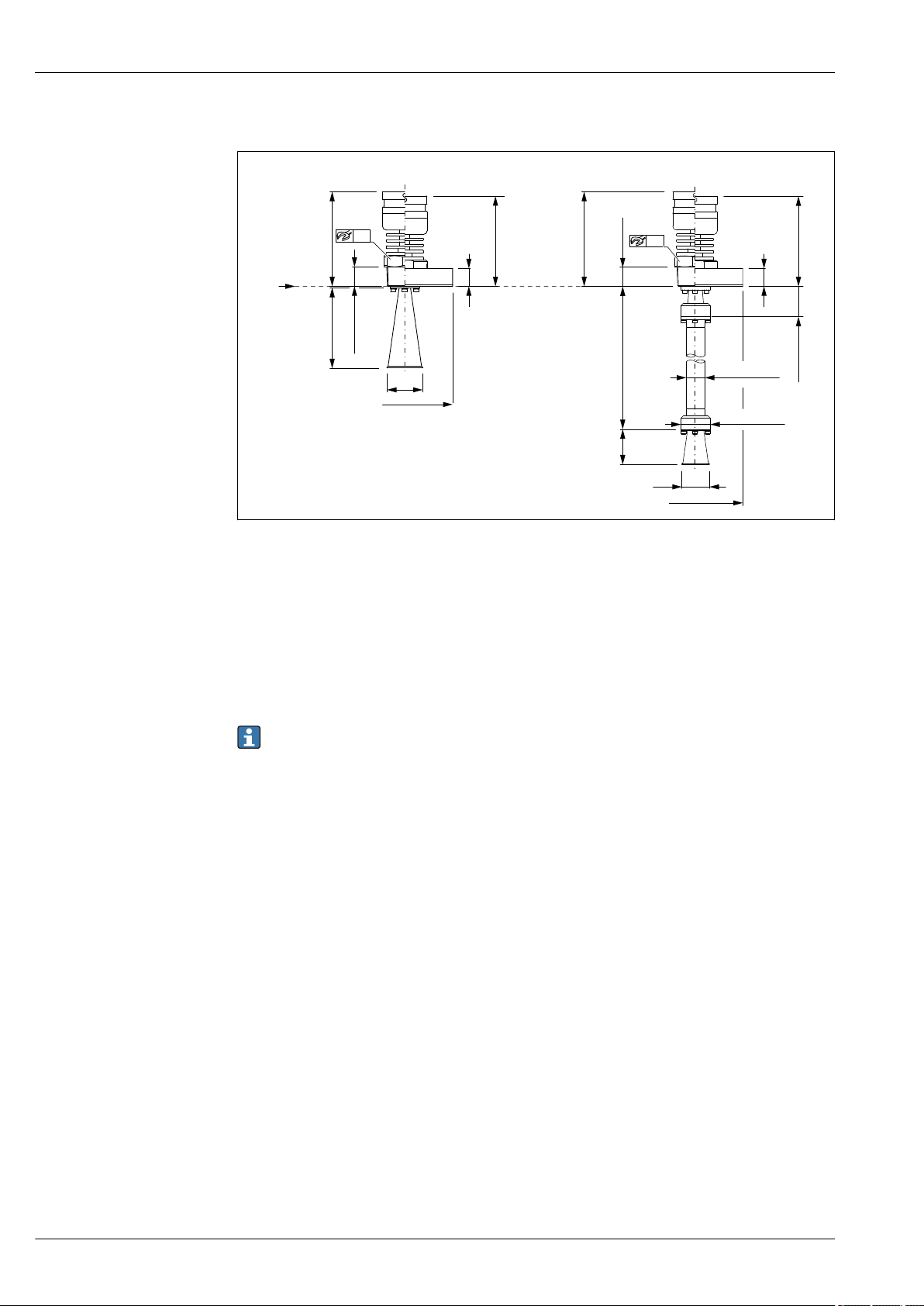
FMR51: Version T ≤ 250 °C (482 °F)
A
B
R
L
122 (4.8)
116(4.57)
26 (1.02)
b
ød
55
øD
C
D
122 (4.8)
116(4.57)
26 (1.02)
b
55
øD
47 (1.85)
ød
101...1000
(3.98...39.3)
L2
ø27 (1.06)
ø42.5(1.7)
Micropilot FMR51, FMR52
A0023385
25 FMR51: Version T < 250 °C (482 °F); dimensions: mm (in)
A Process connection: Thread
B Process connection: Flange 316L
C Process connection: Thread; Accessory mounted: ..... mm/inch antenna extension
D Process connection: Flange 316L; Accessory mounted: ..... mm/inch antenna extension
R Reference point of the measurement
Valid for the following device versions
Feature 090 "Seal":
D3: Graphite, -40...250°C/-40...482°F
• Dimensions of the horn antenna (L, ⌀d): → 68
• Dimensions of the process connection (⌀D, b): → 68
66 Endress+Hauser
Page 67
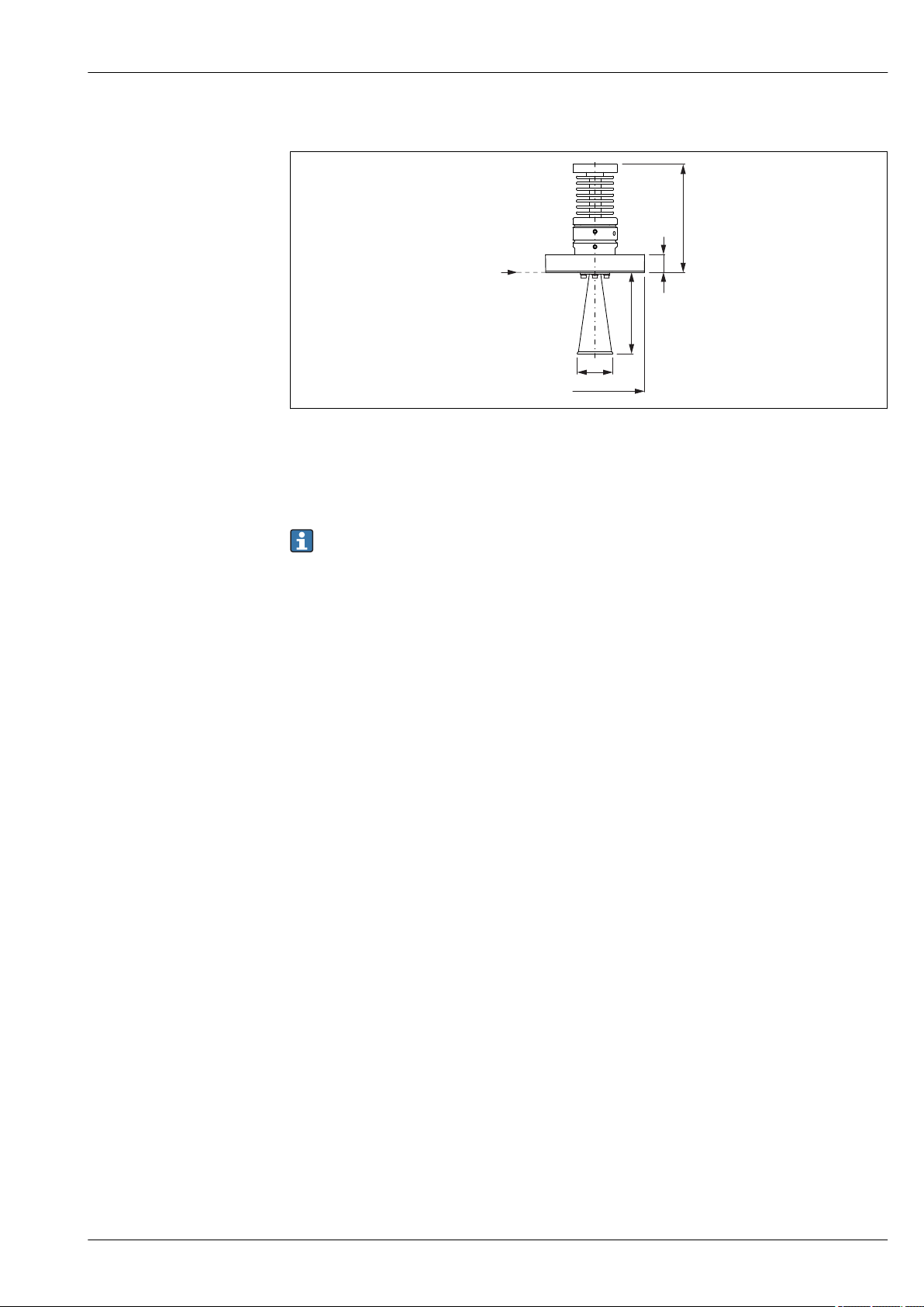
Micropilot FMR51, FMR52
L
141 (5.55)
b
ød
øD
R
FMR51: Version T ≤ 450 °C (842 °F)
A0023386
26 FMR51: Version T < 450 °C (842 °F); dimensions: mm (in)
Valid for the following device versions
Feature 090 "Seal":
D2: Graphite, -196...450°C/-321...842°F
• Dimensions of the horn antenna (L, ⌀d): → 68
• Dimensions of the process connection (⌀D, b): → 68
Endress+Hauser 67
Page 68
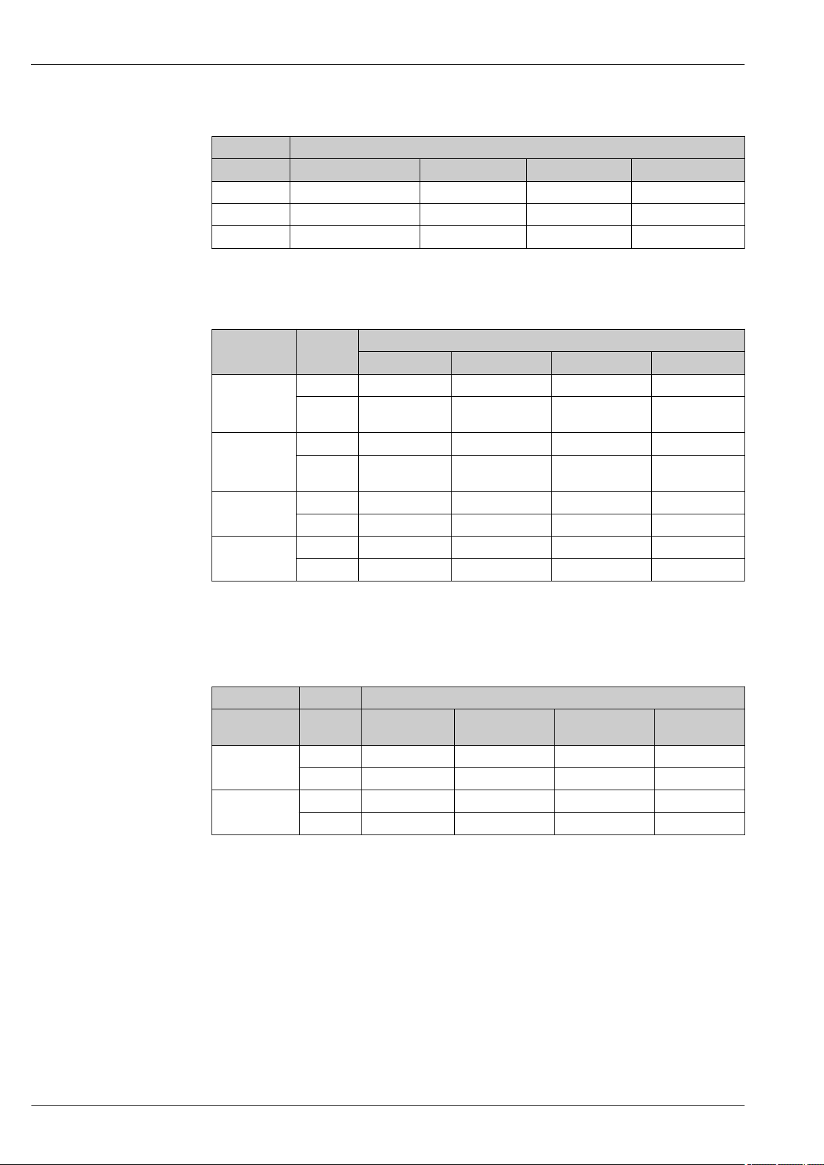
Micropilot FMR51, FMR52
FMR51: Dimensions of the horn antenna
Feature 070 "Antenna"
Dimension BA: Horn 40mm/1-1/2" BB: Horn 50mm/2" BC: Horn 80mm/3" BD: Horn 100mm/4"
L 86 mm (3.39 in) 115 mm (4.53 in) 211 mm (8.31 in) 282 mm (11.1 in)
L2 51 mm (2.01 in) 80 mm (3.15 in) 176 mm (6.93 in) 247 mm (9.72 in)
d 40 mm (1.57 in) 48 mm (1.89 in) 75 mm (2.95 in) 95 mm (3.74 in)
FMR51: Dimensions of the process connections
Flanges according to EN1092-1 (suitable for DIN2527)
Pressure rating Dimension Nominal diameter
1)
2)
DN50 DN80 DN100 DN150
b 18 mm (0.71 in) 20 mm (0.79 in) 20 mm (0.79 in) 22 mm (0.87 in)
PN10/16
⌀D
165 mm (6.5 in) 200 mm
(7.87 in)
220 mm (8.66 in) 285 mm
(11.2 in)
b 20 mm (0.79 in) 24 mm (0.94 in) 24 mm (0.94 in) -
PN25/40
⌀D
165 mm (6.5 in) 200 mm
(7.87 in)
235 mm (9.25 in) -
PN63 b - - 30 mm (1.18 in) -
⌀D - - 250 mm (9.84 in) -
PN100 b - - 36 mm (1.42 in) -
⌀D - - 265 mm (10.4 in) -
1) For flanges with a higher pressure rating than those listed in the product structure please contact Endress
+Hauser.
2) see feature 100 "Process connection"
Flanges according to JIS B2220
Pressure
2)
rating
Dimension 50A 80A 100A 150A
1)
Nominal diameter
2)
b 16 mm (0.63 in) 18 mm (0.71 in) 18 mm (0.71 in) 22 mm (0.87 in)
10K
D 155 mm (6.1 in) 185 mm (7.28 in) 210 mm (8.27 in) 280 mm (11 in)
63K b - - 44 mm (1.73 in) -
D - - 270 mm (10.6 in) -
1) For flanges with a higher pressure rating than those listed in the product structure please contact Endress
+Hauser.
2) see feature 100 "Process connection"
68 Endress+Hauser
Page 69
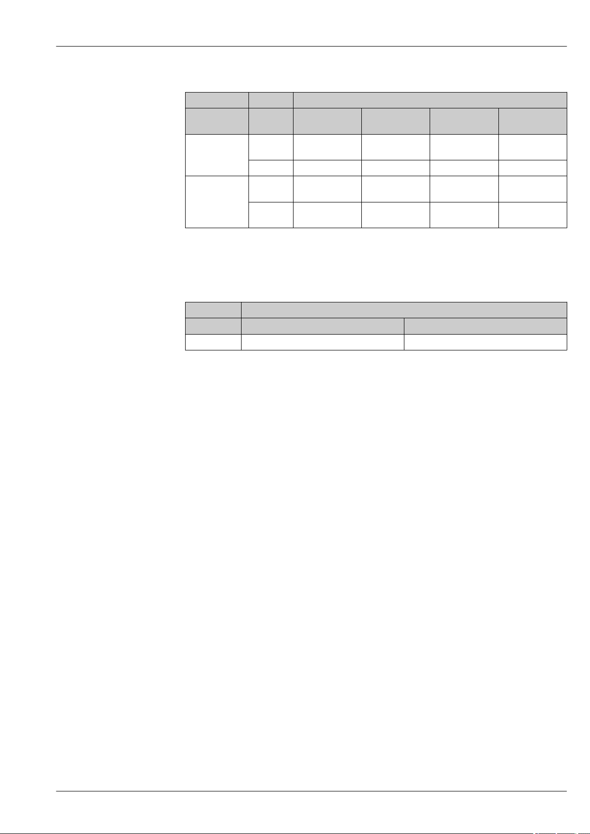
Micropilot FMR51, FMR52
Flanges according to ANSI B16.5
Pressure
2)
rating
150 lbs
Dimension 2" 3" 4" 6"
b 17.5 mm
1)
(0.69 in)
22.3 mm
(0.88 in)
Nominal diameter
22.3 mm
(0.88 in)
2)
23.9 mm
(0.94 in)
D 150 mm (6 in) 190 mm (7.5 in) 230 mm (9 in) 280 mm (11 in)
300 lbs b 20.7 mm
27 mm (1.1 in) 30.2 mm (1.2 in) 35 mm (1.4 in)
(0.81 in)
D 165 mm (6.5 in) 210 mm
(8.25 in)
255 mm (10 in) 320 mm
(12.5 in)
1) For flanges with a higher pressure rating than those listed in the product structure please contact Endress
+Hauser.
2) see feature 100 "Process connection"
Tri-Clamp according to ISO 2852
Nominal diameter
Dimension DN40-51 (2") DN70-76.1 (3")
A 64 mm (2.52 in) 91 mm (3.58 in)
1) see feature 100 "Process connection"
1)
Endress+Hauser 69
Page 70
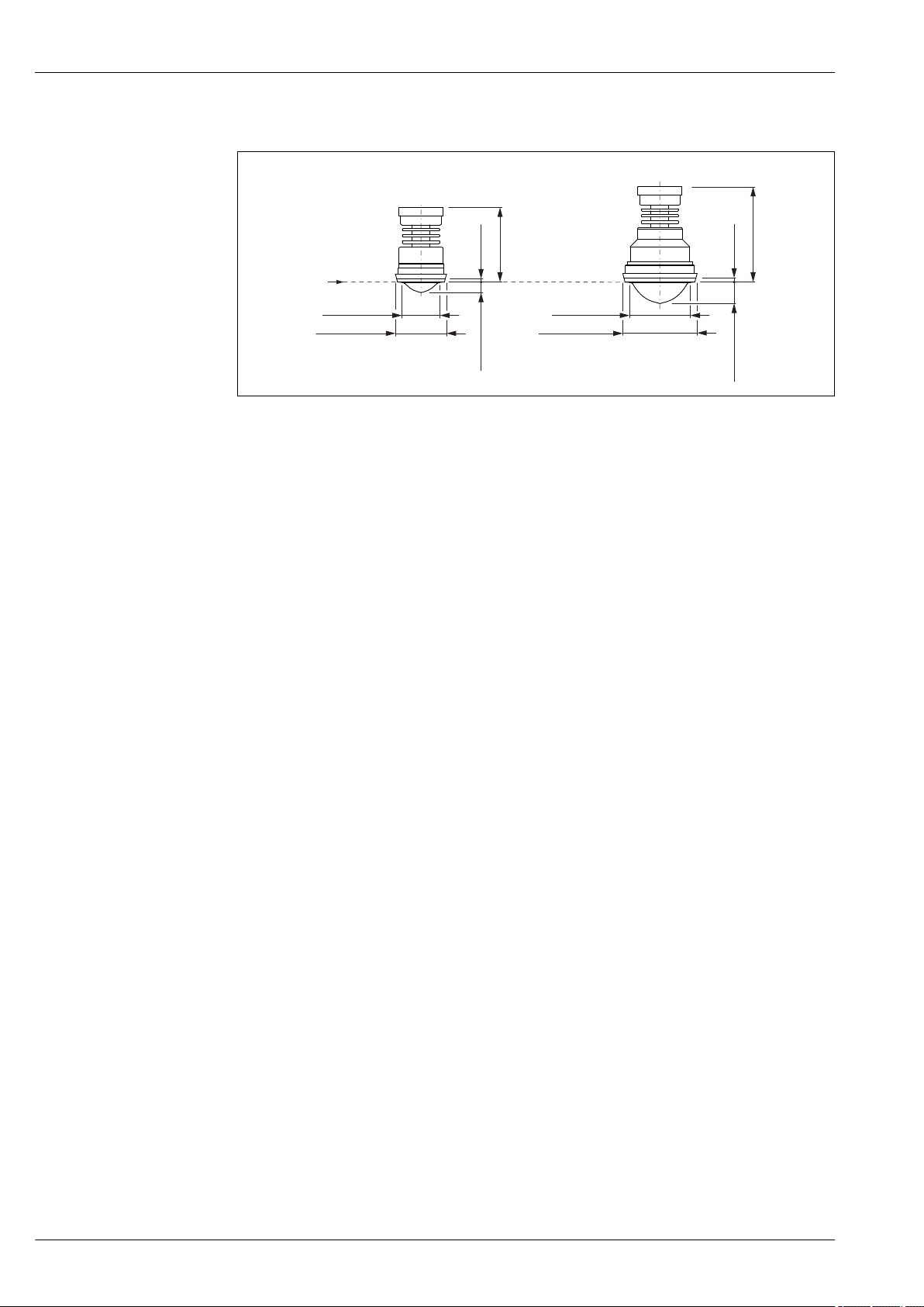
FMR52 with dairy coupling DIN11851
R
A
B
ø100 (3.94)
ø49 (1.93)
ø68.5 (2.7)
ø81 (3.19)
14 (0.55)
29 (1.14)
5 (0.2)
6 (0.24)
90 (3.54)
122 (4.8)
27 FMR52 with dairy coupling DIN11851; dimensions: mm (in)
A Antenna: Horn 50mm/2"; Process connection DIN11851 DN50 PN25
B Antenna: Horn 80mm/3"; Process connection DIN11851 DN80 PN25
R Reference point of the measurement
Micropilot FMR51, FMR52
A0023387
Valid for the following device versions:
Feature 100 "Process connection"
– MRK: DIN11851 DN50 PN25 slotted nut, PTFE>316L (diagram A)
– MTK: DIN11851 DN80 PN25 slotted nut, PTFE>316L (diagram B)
70 Endress+Hauser
Page 71
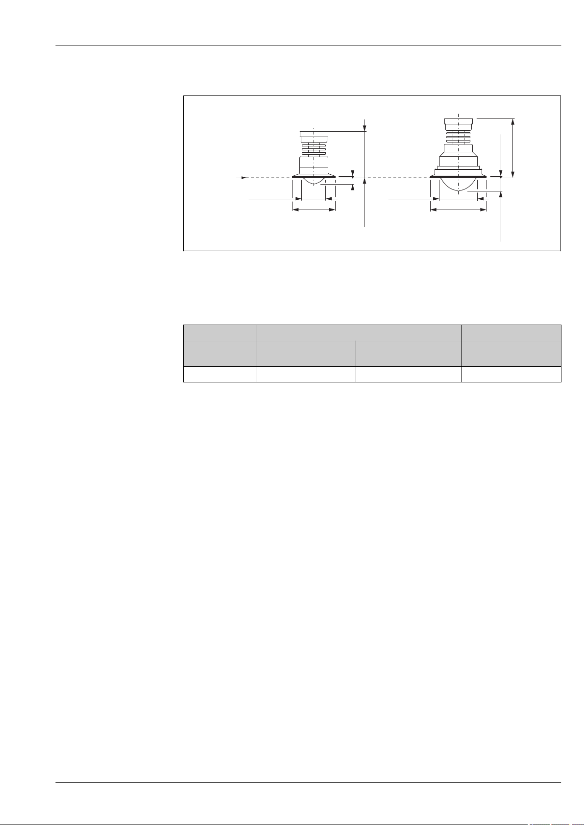
Micropilot FMR51, FMR52
R
A B
øa
øa
ø81 (3.19)
ø49 (1.93)
29 (1.14)
14 (0.55)
2.6 (0.1)
2.6 (0.1)
120 (4.72)
93(3.66)
FMR52 with Tri-Clamp ISO2852
A0023388
28 FMR52 with Tri-Clamp ISO2852; dimensions: mm (in)
A Antenna: Horn 50mm/2"
B Antenna: Horn 80mm/3"
R Reference point of the measurement
Antenna
Process
connection
a 64 mm (2.52 in) 91 mm (3.58 in) 119 mm (4.69 in)
1) Feature 070 of the product structure
2) Feature 100 of the product structure
1)
2)
TDK: Tri-Clamp DN40-51
(2")
BO: "Horn 50mm/2" BP: Horn 80mm/3"
TFK: Tri-Clamp DN70-76.1
(3")
THK: Tri-Clamp DN101.6
(4")
Endress+Hauser 71
Page 72
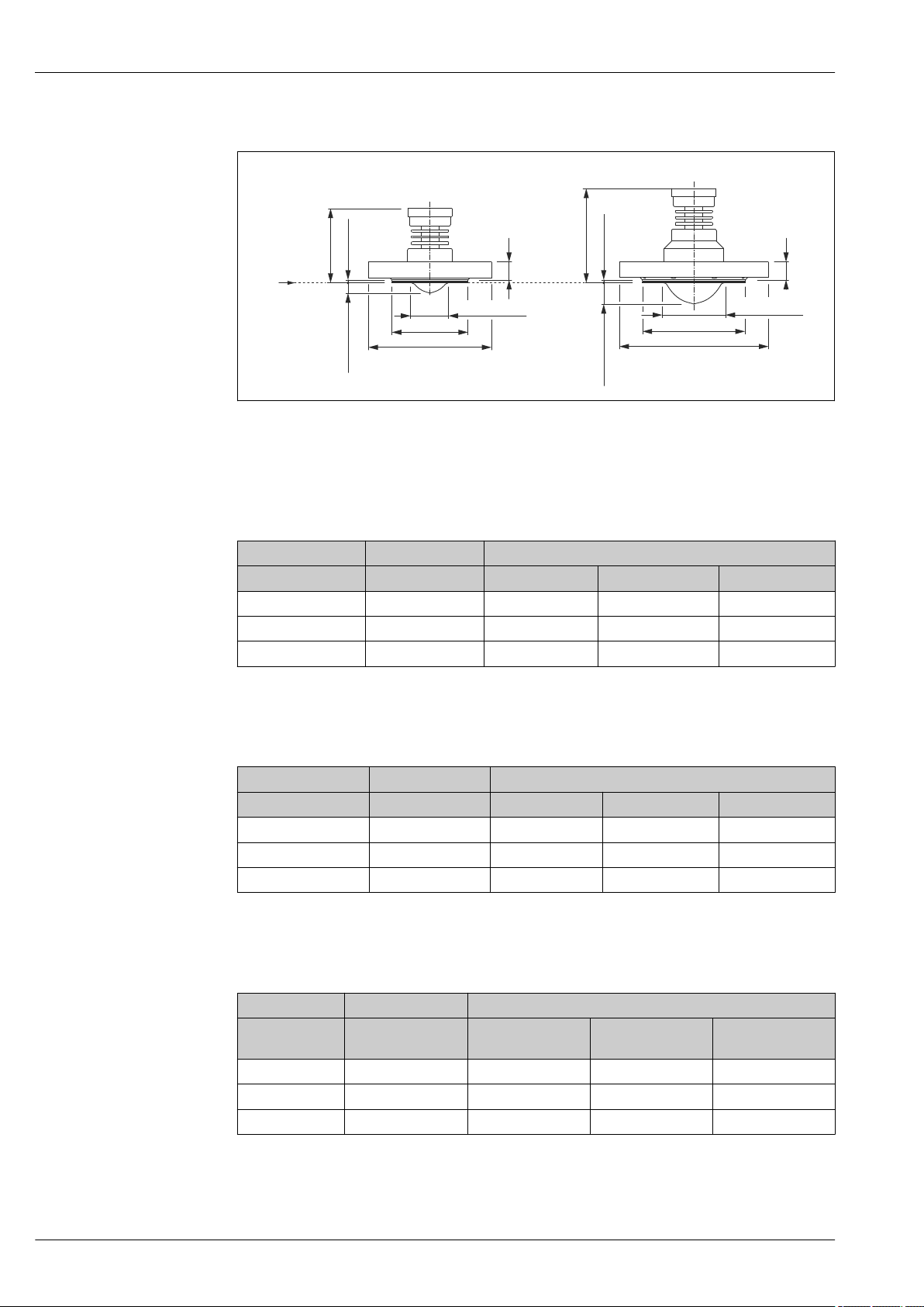
FMR52 with flange
R
A
B
øb
øb
øc
øc
28.6 (1.13)
13.8 (0.54)
4 (0.16)
a
a
4 (0.16)
94(3.7)
121(4.76)
ø48 (1.89)
ø75 (2.95)
29 Dimensions FMR52 with flange; dimensions: mm (in)
A Antenna: Horn 50mm/2"
B Antenna: Horn 80mm/3"
R Reference point of the measurement
Micropilot FMR51, FMR52
A0023389
Flanges according to EN1092-1 (suitable for DIN2527)
Antenna
Process connection
a 20 mm (0.79 in) 20 mm (0.79 in) 20 mm (0.79 in) 22 mm (0.87 in)
b 102 mm (4.02 in) 138 mm (5.43 in) 158 mm (6.22 in) 212 mm (8.35 in)
c 165 mm (6.5 in) 200 mm (7.87 in) 220 mm (8.66 in) 285 mm (11.2 in)
1) Feature 70 of the product structure
2) Feature 100 of the product structure
1)
BO: Horn 50mm/2" BP: Horn 80mm/3"
2)
CFK: Flange DN50 CGK: Flange DN80 CHK: Flange DN100 CJK: Flange DN150
Flanges according to ANSI B16.5
Antenna
Process connection
a 17.5 mm (0.69 in) 22.3 mm (0.88 in) 22.3 mm (0.88 in) 23.9 mm (0.94 in)
b 92 mm (3.62 in) 127 mm (5 in) 158 mm (6.22 in) 212 mm (8.35 in)
c 150 mm (6 in) 190 mm (7.5 in) 230 mm (9 in) 280 mm (11 in)
1) Feature 70 of the product structure
2) Feature 100 of the product structure
1)
BO: Horn 50mm/2" BP: Horn 80mm/3"
2)
FK: Flange 2" AGK: Flange 3" AHK: Flange 4" AJK: Flange 6"
Flanges according to JIS B2220
1)
2)
BO: Horn 50mm/2" BP: Horn 80mm/3"
KFK: Flange 10K
50A
KGK: Flange 10K
80A
KHK: Flange 10K
100A
KJK: Flange 10K
150A
Antenna
Process
connection
a 16 mm (0.63 in) 18 mm (0.71 in) 18 mm (0.71 in) 22 mm (0.87 in)
b 96 mm (3.78 in) 127 mm (5 in) 151 mm (5.94 in) 212 mm (8.35 in)
c 155 mm (6.1 in) 185 mm (7.28 in) 210 mm (8.27 in) 280 mm (11 in)
1) Feature 70 of the product structure
2) Feature 100 of the product structure
72 Endress+Hauser
Page 73

Micropilot FMR51, FMR52
Weight
Housing
Part Weight
Housing GT18 - stainless steel approx.
4.5 kg (9.9 lb)
Housing GT19 - plastic approx.
1.2 kg (2.7 lb)
Housing GT20 - aluminium approx.
1.9 kg (4.2 lb)
Antenna and process connection
Device Weight of antenna and process connection
FMR51 max. 3.0 kg (6.6 lb) + weight of flange
FMR52 max. 4 kg (8.8 lb) + weight of flange
1) For the weight of the flange refer to Technical Information TI00426F.
1)
1)
Endress+Hauser 73
Page 74
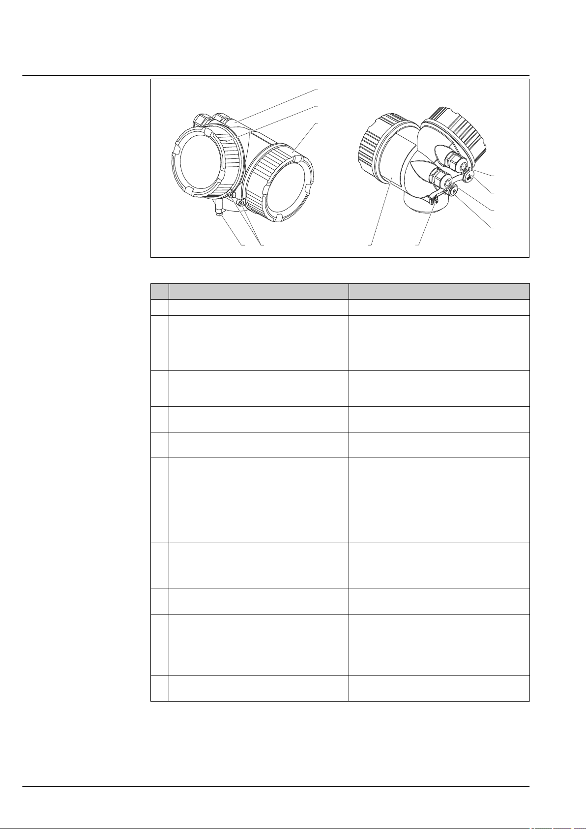
Materials: GT18 housing
2.1
1
2.2
5.2
5.1
6
7
8
94 3
(stainless steel, corrosionresistant)
Micropilot FMR51, FMR52
No. Part Material
1 Housing CF3M similar to 316L/1.4404
2.1 Cover of the electronics compartment • Cover: CF3M (similar to 316L/1.4404)
• Window: glass
• Cover seal: NBR
• Seal of the window: NBR
• Thread-coating: Graphite-based lubricant varnish
2.2 Cover of the terminal compartment • Cover: CF3M (similar to 316L/1.4404)
• Cover seal: NBR
• Thread-coating: Graphite-based lubricant varnish
3 Cover lock • Screw: A4
• Clamp: 316L (1.4404)
4 Lock at the housing neck • Screw: A4-70
• Clamp: 316L (1.4404)
5.1 Dummy plug, cable gland, adapter or plug
(depending on the device version)
5.2 Dummy plug, cable gland or adapter (depending on
the device version)
6 Dummy plug or M12 socket (depending on the
device version)
7 Pressure relief stopper 316L (1.4404)
8 Ground terminal • Screw: A4
9 Nameplate • Plate: 316L (1.4404)
1) For the version with M12 plug the sealing material is Viton.
2) For the version with 7/8" plug, the sealing material is NBR.
• Dummy plug, depending on the device version:
– PE
– PBT-GF
• Cable gland: 316L (1.4404) or nickel-plated brass
• Adapter: 316L (1.4404/1.4435)
• Seal: EPDM
• M12 plug: Nickel-plated brass
• 7/8" plug: 316 (1.4401)
• Dummy plug: 316L (1.4404)
• Cable gland: 316L (1.4404) or nickel-plated brass
• Adapter: 316L (1.4404/1.4435)
• Seal: EPDM
• Dummy plug: 316L (1.4404)
• M12 socket: 316L (1.4404)
• Spring washer: A4
• Clamp: 316L (1.4404)
• Holder: 316L (1.4404)
• Groove pin: A4 (1.4571)
1)
2)
A0013788
74 Endress+Hauser
Page 75
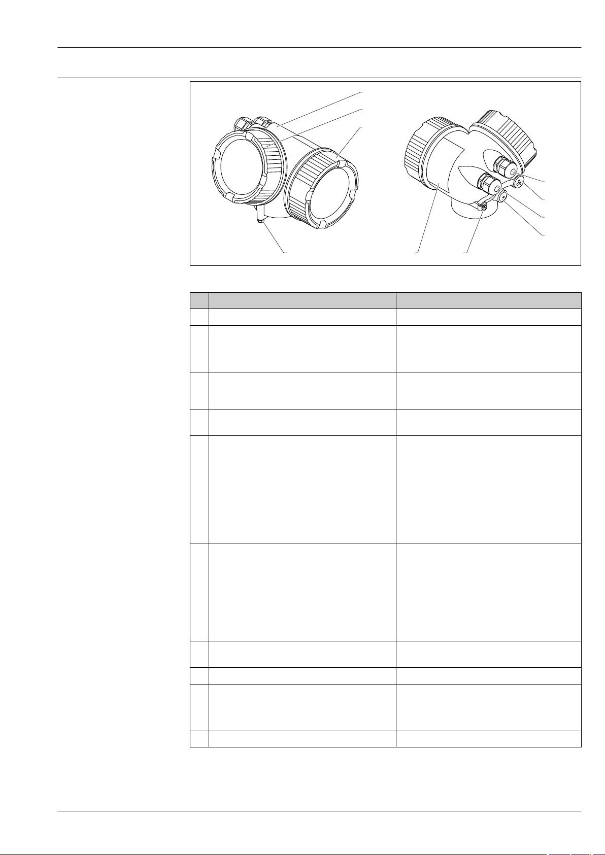
Micropilot FMR51, FMR52
2.1
1
2.2
5.2
5.1
6
7
8
94
Materials: GT19 housing (plastic)
No. Part Material
1 Housing PBT
2.1 Cover of the electronics compartment • Cover glass: PC
• Cover frame: PBT-PC
• Cover seal: EPDM
• Thread-coating: Graphite-based lubricant varnish
2.2 Cover of the terminal compartment • Cover: PBT
• Cover seal: EPDM
• Thread-coating: Graphite-based lubricant varnish
4 Lock at the housing neck • Screw: A4-70
• Clamp: 316L (1.4404)
5.1 Dummy plug, cable gland, adapter or plug
(depending on the device version)
5.2 Dummy plug, cable gland or adapter (depending on
the device version)
6 Dummy plug or M12 socket (depending on the
device version)
7 Pressure relief stopper Nickel-plated brass (CuZn)
8 Ground terminal • Screw: A2
9 Adhesive nameplate Plastic
• Dummy plug, depending on the device version:
– PE
– PBT-GF
• Cable gland, depending on the device version:
– Nickel-plated brass (CuZn)
– PA
• Adapter: 316L (1.4404/1.4435)
• Seal: EPDM
• M12 plug: Nickel-plated brass
• 7/8" plug: 316 (1.4401)
• Dummy plug, depending on the device version:
– PE
– PBT-GF
– Nickel-plated steel
• Cable gland, depending on the device version:
– Nickel-plated brass (CuZn)
– PA
• Adapter: 316L (1.4404/1.4435)
• Seal: EPDM
• Dummy plug: Nickel-plated brass (CuZn)
• M12 socket: Nickel-plated GD-Zn
• Spring washer: A4
• Clamp: 304 (1.4301)
• Holder: 304 (1.4301)
A0013788
1)
2)
1) For the version with M12 plug the sealing material is Viton.
2) For the version with 7/8" plug, the sealing material is NBR.
Endress+Hauser 75
Page 76
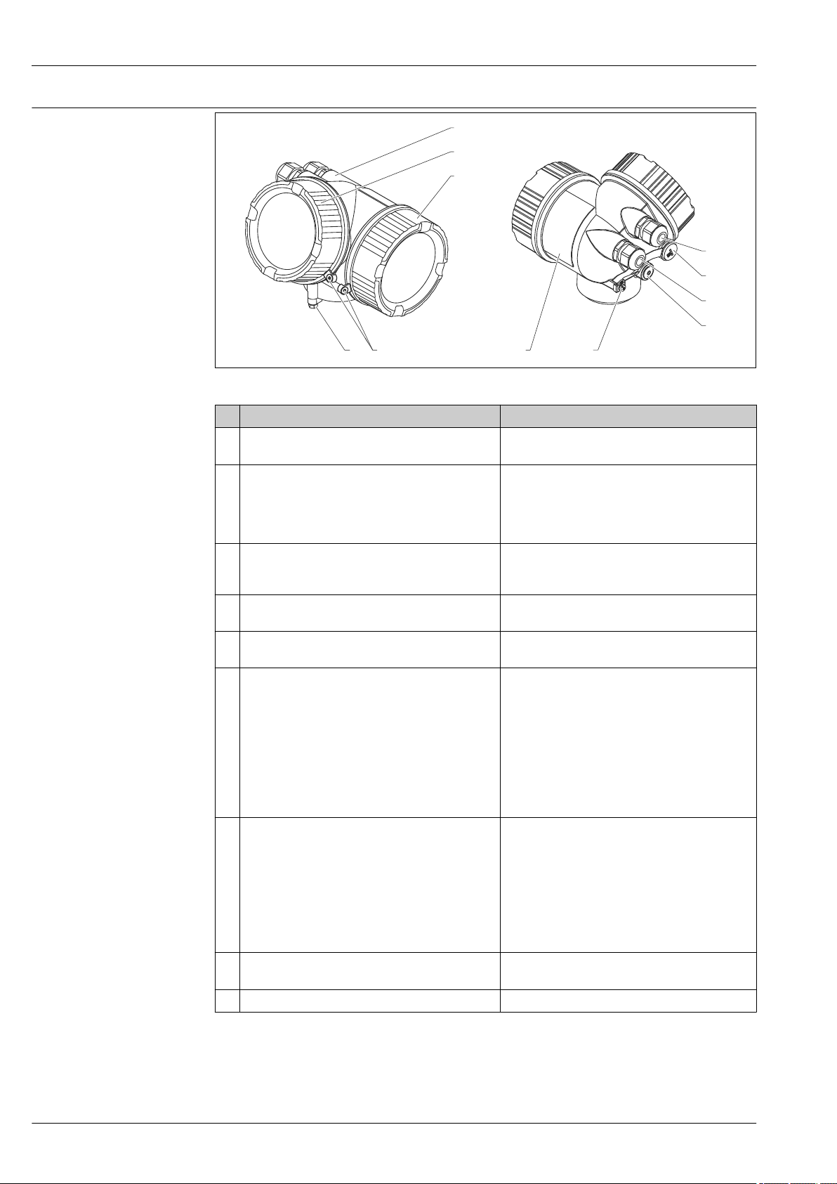
Materials: GT20 housing
2.1
1
2.2
5.2
5.1
6
7
8
94 3
(die-cast aluminum, powdercoated)
Micropilot FMR51, FMR52
Nr. Part Material
1 Housing, RAL 5012 (blue) • Housing: AlSi10Mg(<0,1% Cu)
• Coating: Polyester
2.1 Cover of the electronics compartment; RAL 7035
(gray)
2.2 Cover of the terminal compartment; RAL 7035
(gray)
3 Cover lock • Screw: A4
4 Lock at the housing neck • Screw: A4-70
5.1 Dummy plug, cable gland, adapter or plug
(depending on the device version)
5.2 Dummy plug, cable gland or adapter (depending on
the device version)
6 Dummy plug or M12 socket (depending on the
device version)
7 Pressure relief stopper Nickel-plated brass (CuZn)
• Cover: AlSi10Mg(<0,1% Cu)
• Window: Glass
• Cover seal: NBR
• Seal of the window: NBR
• Thread-coating: Graphite-based lubricant varnish
• Cover: AlSi10Mg(<0,1% Cu)
• Cover seal: NBR
• Thread-coating: Graphite-based lubricant varnish
• Clamp: 316L (1.4404)
• Clamp: 316L (1.4404)
• Dummy plug, depending on the device version:
– PE
– PBT-GF
• Cable gland, depending on the device version:
– Nickel-plated brass (CuZn)
– PA
• Adapter: 316L (1.4404/1.4435)
• Seal: EPDM
• M12 plug: Nickel-plated brass
• 7/8" plug: 316 (1.4401)
• Dummy plug, depending on the device version:
– PE
– PBT-GF
– Nickel-plated steel
• Cable gland, depending on the device version:
– Nickel-plated brass (CuZn)
– PA
• Adapter: 316L (1.4404/1.4435)
• Seal: EPDM
• Dummy plug : Nickel-plated brass (CuZn)
• M12 socket: Nickel-plated GD-Zn
2)
A0013788
1)
76 Endress+Hauser
Page 77
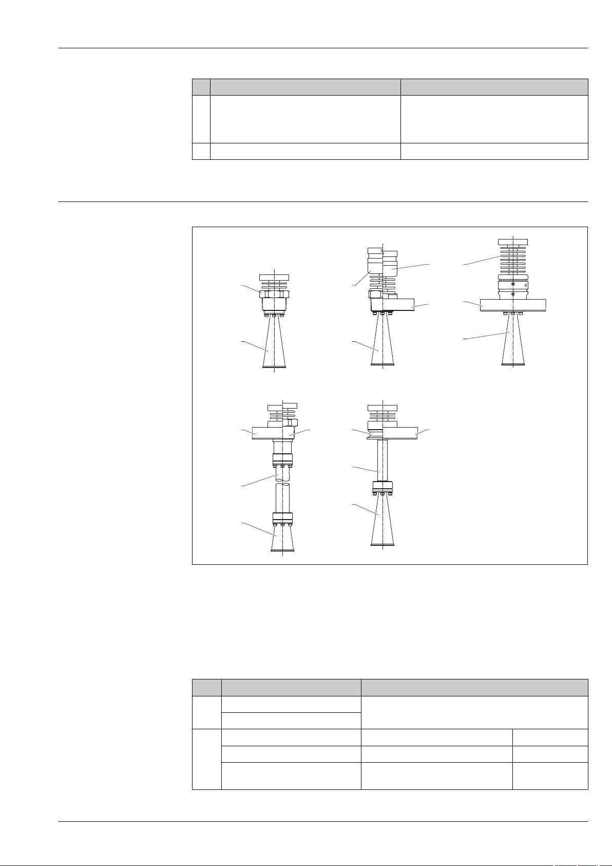
Micropilot FMR51, FMR52
A
E
F
G H
D
B C
1 7
7
3
2
2
5
2
4
3
6
3
3
6
2 2
7
Nr. Part Material
8 Ground terminal • Screw: A2
• Spring washer: A2
• Clamp: 304 (1.4301)
• Holder: 304 (1.4301)
9 Adhesive nameplate Plastic
1) For the version with M12 plug the sealing material is Viton.
2) For the version with 7/8" plug, the sealing material is NBR.
Materials: Antenna and process connection
FMR51
Endress+Hauser 77
A Version with screw-in adapter
B XT version with threaded connection
C XT version with flange
D HT version with flange
E Version with flange and antenna extension > 100 mm (3.94 in) to 500 mm (19.7 in)
F Version with threaded connection and antenna extension > 100 mm (3.94 in) to 500 mm (19.7 in)
G Version with clamp adapter and antenna extension 100 mm (3.94 in)
H Version with flange and antenna extension 100 mm (3.94 in)
Pos. Part Material
1 Process adapter 316L (1.4404)
Locking washer
2 Horn 316L (1.4404) AlloyC22 (2.4602)
Screws A4 AlloyC22 (2.4602)
Spring-lock washer (compact version) A4 without spring-lock
washer
A0018961
Page 78
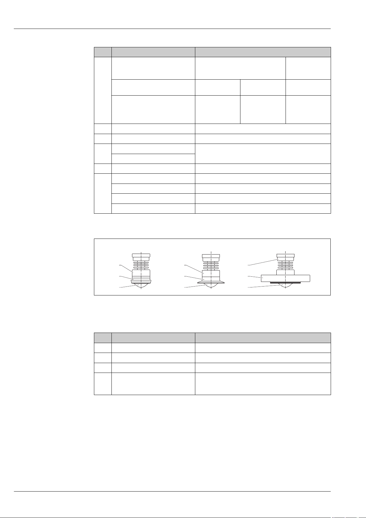
Micropilot FMR51, FMR52
A
B C
1
2
4 4 4
2 3
1
1
Pos. Part Material
Nordlock washer
(extension >100 mm, XT and HT
version)
Process separation cone Standard:
Seal Standard:
3 Flange 316L (1.4404/1.4435) optionally AlloyC22 (2.4602) clad
4 Tube extension + adapter 316L (1.4404)
5 Extension process adapter 316L (1.4404)
Locking washer
6 Process adapter 316L (1.4404)
7 Housing adapter 316L (1.4404)
Temperature reduction (XT) 316L (1.4404)
Intermediate adapter (HT) 316L (1.4404)
Process adapter 316L (1.4404)
A4 without Nordlock
washer
PTFE
• Viton: FKM
• Kalrez: FFKM
(K6375)
XT:
PEEK
XT:
Graphite
HT:
Al2O
3
HT:
Graphite
FMR52
A Dairy coupling
B Clamp adapter
C Flange version
Pos. Part Material
1 Adapter 304 (1.4301)
2 Process connection 316L (1.4435)
3 Flange 316L (1.4404/1.4435)
4 Cladding PTFE
(in accordance with FDA 21 CFR 177.1550 and USP <88>
Class VI)
A0018951
78 Endress+Hauser
Page 79
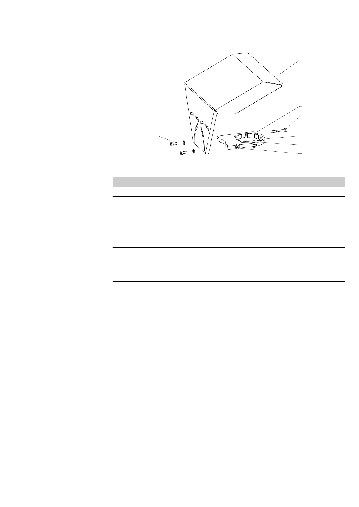
Micropilot FMR51, FMR52
1
2
3
4
5
7
6
Materials: Weather protection cover
A0015473
No Part: Material
1 Protection cover: 316L (1.4404)
2 Molded rubber part (4x): EPDM
3 Clamping screw: 316L (1.4404) + carbon fibre
4 Bracket: 316L (1.4404)
5 • Cheese head screw: A4-70
• Nut: A4
• Spring washer: A4
6 Ground terminal
• Screw: A4
• Spring washer: A4
• Clamp: 316L (1.4404)
• Holder: 316L (1.4404)
7 • Washer: A4
• Cheese head screw: A4-70
Endress+Hauser 79
Page 80

Operability
Micropilot FMR51, FMR52
Operating concept
Operator-oriented menu structure for user-specific tasks
• Commissioning
• Operation
• Diagnostics
• Expert level
Operating languages
• English
• Deutsch
• Français
• Español
• Italiano
• Nederlands
• Portuguesa
• Polski
• русский язык (Russian)
• Svenska
• Türkçe
• 中文 (Chinese)
• 日本語 (Japanese)
• 한국어 (Korean)
• Bahasa Indonesia
• tiếng Việt (Vietnamese)
• čeština (Czech)
Feature 500 of the product structure determines which of these languages is preset on delivery.
Quick and save commissioning
• Interactive wizard with graphical interface for easy commissioning via FieldCare/DeviceCare
• Menu guidance with brief explanations of the individual parameter functions
• Standardized operation at the device and in the operating tools
Integrated data storage device (HistoROM)
• Enables transfer of configuration when changing electronic modules
• Records up to 100 event messages in the device
• Records up to 1000 measured values in the device
• Saves the signal curve on commissioning which can later be used as a reference.
Efficient diagnostics increase measurement reliability
• Remedy information is integrated in plain text
• Diverse simulation options and line recorder functions
80 Endress+Hauser
Page 81
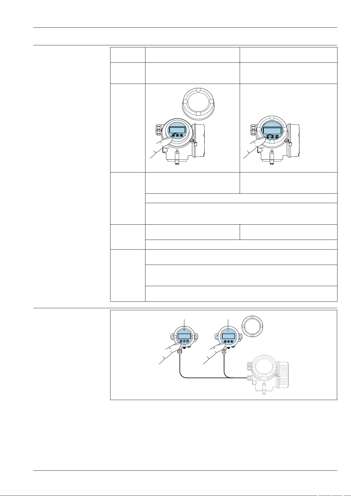
Micropilot FMR51, FMR52
1 2
Local operation
Operation
with
Order code for
"Display;
Operation"
Display
elements
Operating
elements
Additional
functionality
Pushbuttons Touch Control
Option C "SD02" Option E "SD03"
A0032219 A0032221
4-line display 4-line display
white background lighting; switches to red in
event of device error
Format for displaying measured variables and status variables can be individually configured
Permitted ambient temperature for the display: –20 to +70 °C (–4 to +158 °F)
The readability of the display may be impaired at temperatures outside the temperature
range.
local operation with 3 push buttons (, ,)external operation via touch control; 3 optical
keys: , ,
Operating elements also accessible in various hazardous areas
Data backup function
The device configuration can be saved in the display module.
Data comparison function
The device configuration saved in the display module can be compared to the current device
configuration.
Data transfer function
The transmitter configuration can be transmitted to another device using the display module.
Operation with remote display and operating module FHX50
30 FHX50 operating options
1 Housing of the remote display and operating module FHX50
2 Display and operating module SD02, push buttons; cover must be removed
3 Display and operating module SD03, optical keys; can be operated through the glass of the cover
Endress+Hauser 81
A0032215
Page 82
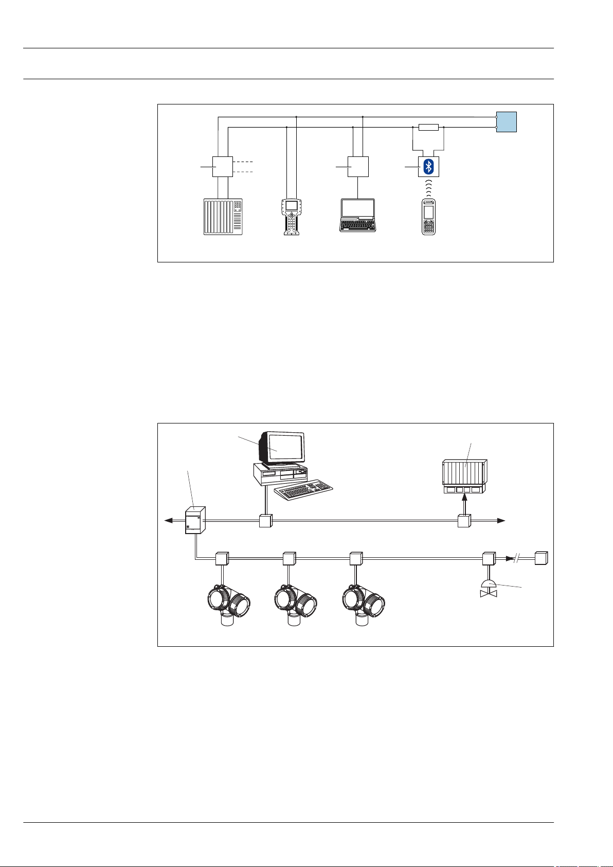
Remote operation Via HART protocol
1 4 5 7
9
6 8
2
3
ENDRESS + HAUSER
T
PROFIBUS DP
PROFIBUS PA
1
2
3
5
4 4 4
31 Options for remote operation via HART protocol
1 PLC (programmable logic controller)
2 Transmitter power supply unit, e.g. RN221N (with communication resistor)
3 Connection for Commubox FXA191, FXA195 and Field Communicator 375, 475
4 Field Communicator 475
5 Computer with operating tool (e.g. DeviceCare/FieldCare , AMS Device Manager, SIMATIC PDM)
6 Commubox FXA191 (RS232) or FXA195 (USB)
7 Field Xpert SFX350/SFX370
8 VIATOR Bluetooth modem with connecting cable
9 Transmitter
Micropilot FMR51, FMR52
A0028746
Via PROFIBUS PA protocol
A0015775
1 Segment coupler
2 Computer with Profiboard/Proficard and operating tool (e.g. DeviceCare/FieldCare
3 PLC (Progrommable Logic Controller)
4 Transmitter
5 Additional functions (valves etc.)
82 Endress+Hauser
Page 83
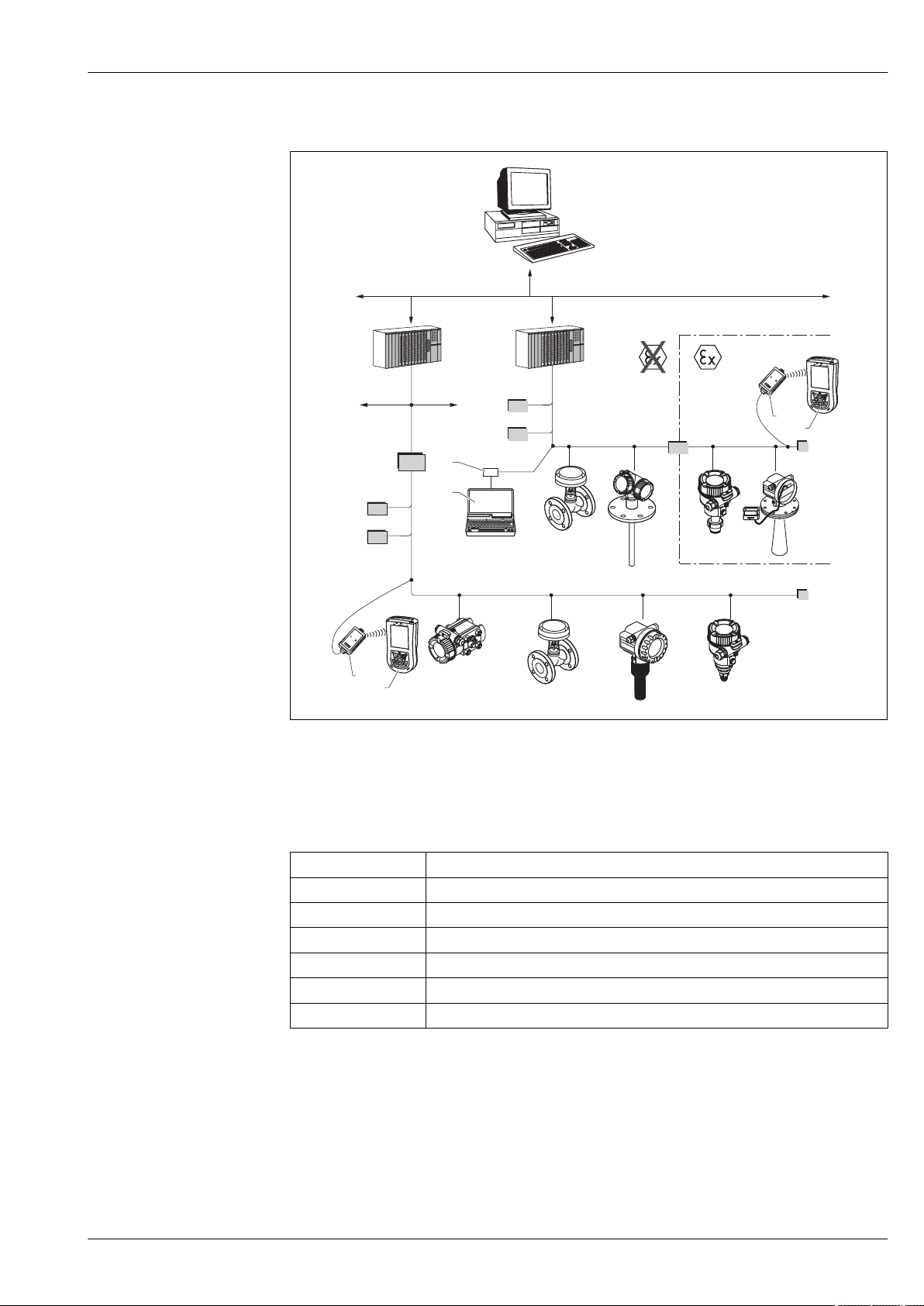
Micropilot FMR51, FMR52
FF-H1
FF-H1
BT
BT
PS
3
4
PS
BT
SB
BT
FF-HSE
IN
LD
ENDRESS + HAUSER
E
+–
%
1
1
2
2
Via FOUNDATION Fieldbus
A0017188
32 FOUNDATION Fieldbus system architecture with associated components
1 FFblue Bluetooth modem
2 Field Xpert SFX350/SFX370
3 DeviceCare/FieldCare
4 NI-FF interface card
IN Industrial network
FF-HSE High Speed Ethernet
FF-H1 FOUNDATION Fieldbus-H1
LD Linking Device FF-HSE/FF-H1
PS Bus Power Supply
SB Safety Barrier
BT Bus Terminator
Endress+Hauser 83
Page 84
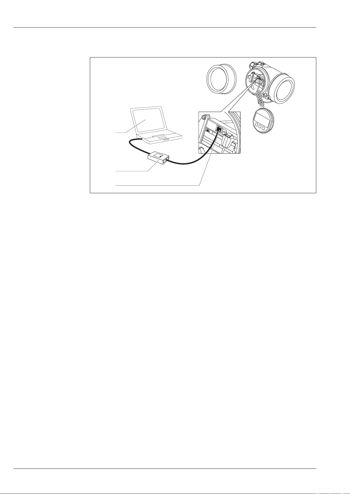
Via service interface (CDI)
1
2
3
Micropilot FMR51, FMR52
1 Service interface (CDI) of the measuring device (= Endress+Hauser Common Data Interface)
2 Commubox FXA291
3 Computer with DeviceCare/FieldCare operating tool
A0032466
84 Endress+Hauser
Page 85
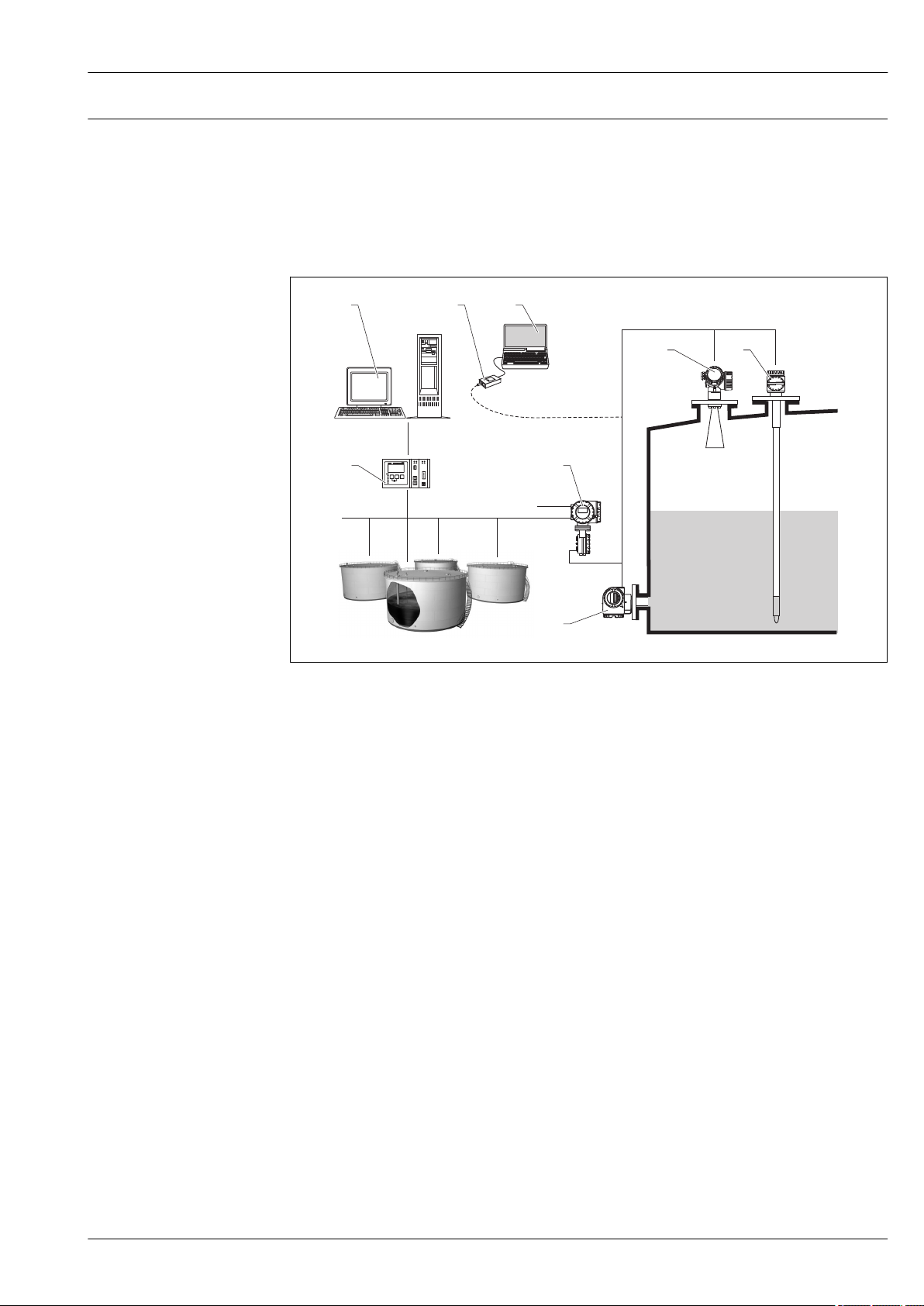
Micropilot FMR51, FMR52
NXA820
16...253 VAC
1 2 3
4
6
7
8
5
Integration in tank gauging system
The Endress+Hauser Tank Side Monitor NRF590 provides integrated communications for sites with
multiple tanks, each with one or more sensors on the tank, such as radar, spot or average
temperature, capacitive probe for water detection and/or pressure sensors. Multiple protocols out of
the Tank Side Monitor guarantee connectivity to nearly any of the existing industry standard tank
gauging protocols. Optional connectivity of analog 4...20 mA sensors, digital I/O and analog output
simplify full tank sensor integration. Use of the proven concept of the intrinsically safe HART bus for
all on-tank sensors yields extremely low wiring costs, while at the same time providing maximum
safety, reliability and data availability.
33 The complete measuring system consists of:
1 Tankvision workstation
2 Commubox FXA195 (USB) - optional
3 Computer with operating tool (ControlCare) - optional
4 Level measuring device
5 Temperature measuring device
6 Tank Side Monitor NRF590
7 Pressure measuring device
8 Tankvision Tank Scanner NXA820
A0017982
Endress+Hauser 85
Page 86

Micropilot FMR51, FMR52
SupplyCare inventory management software
SupplyCare is a web-based operating program for coordinating the flow of material and information
along the supply chain. SupplyCare provides a comprehensive overview of the levels of
geographically distributed tanks and silos, for instance, providing complete transparency over the
current inventory situation, regardless of time and location.
Based on the measuring and transmission technology installed onsite, the current inventory data are
collected and sent to SupplyCare. Critical levels are clearly indicated and calculated forecasts provide
additional security for material requirements planning.
The main functions of SupplyCare:
Inventory visualization
SupplyCare determines the inventory levels in tanks and silos at regular intervals. It displays current
and historical inventory data and calculated forecasts of future demand. The overview page can be
configured to suit the user's preferences.
Master data management
With SupplyCare you can create and manage the master data for locations, companies, tanks,
products and users, as well as user authorization.
Report Configurator
The Report Configurator can be used to create personalized reports quickly and easily. The reports
can be saved in a variety of formats, such as Excel, PDF, CSV and XML. The reports can be
transmitted in many ways, such as by http, ftp or e-mail.
Event management
Events, such as when levels drop below the safety stock level or plan points, are indicated by the
software. In addition, SupplyCare can also notify pre-defined users by e-mail.
Alarms
If technical problems occur, e.g. connection issues, alarms are triggered and alarm e-mails are sent to
the System Administrator and the Local System Administrator.
Delivery planning
The integrated delivery planning function automatically generates an order proposal if a pre-set
minimum inventory level is undershot. Scheduled deliveries and disposals are monitored
continuously by SupplyCare. SupplyCare notifies the user if scheduled deliveries and disposals are not
going to be met as planned.
Analysis
In the Analysis module, the most important indicators for the inflow and outflow of the individual
tanks are calculated and displayed as data and charts. Key indicators of material management are
automatically calculated and form the basis for optimizing the delivery and storage process.
Geographical visualization
All the tanks and the tank inventories are represented graphically on a map (based on Google Maps).
The tanks and inventory situations can be filtered by tank group, product, supplier or location.
Multi-language support
The multi-language user interface supports 9 languages, thereby enabling global collaboration on a
single platform. The language and settings are recognized automatically using the browser settings.
SupplyCare Enterprise
SupplyCare Enterprise runs by default as a service under Microsoft Windows on an application server
in an Apache Tomcat environment. The operators and administrators operate the application via a
Web browser from their workstations.
86 Endress+Hauser
Page 87
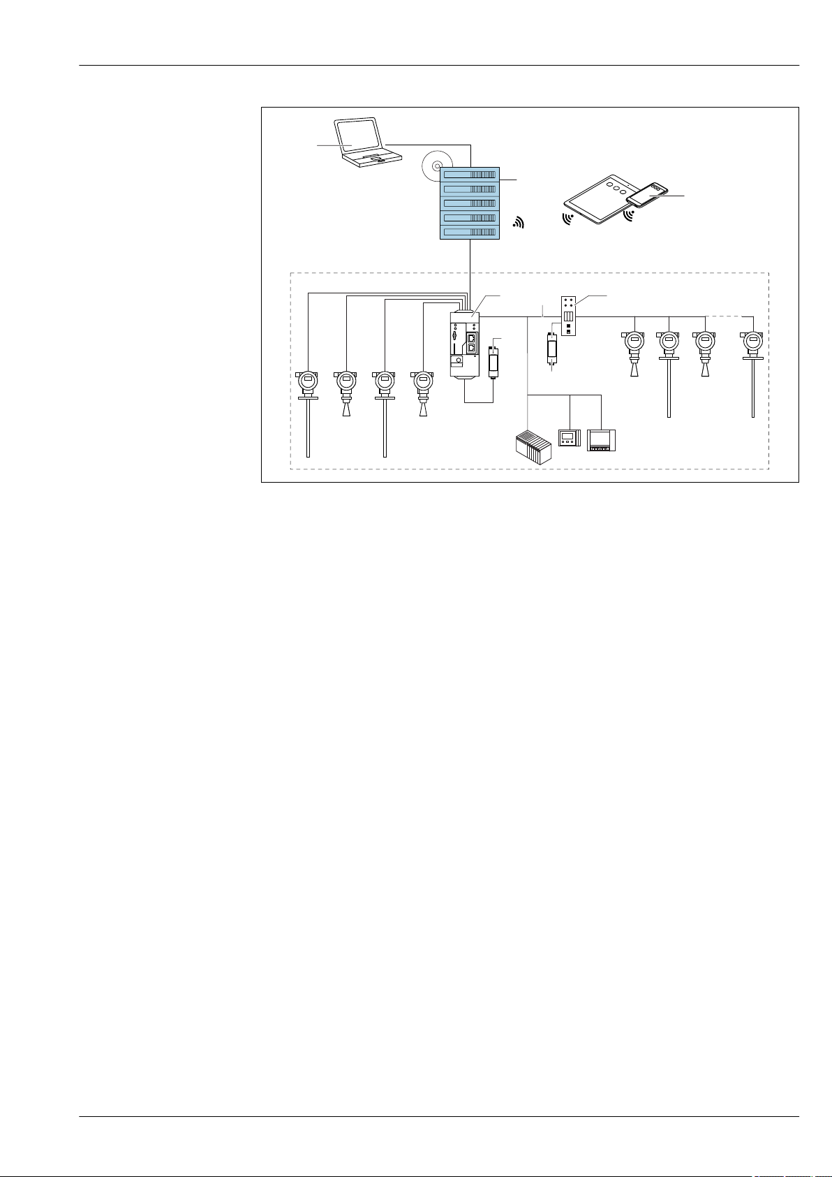
Micropilot FMR51, FMR52
6
.
10
9
1
3
4
6
5 8
7
2
A0034288
34 Example of inventory management platform with SupplyCare Enterprise SCE30B
1 SupplyCare Enterprise (via Web browser)
2 SupplyCare Enterprise installation
3 SupplyCare Enterprise on mobile devices (via Web browser)
4 Ethernet/WLAN/UMTS
5 Fieldgate FXA42
6 Power supply 24 V DC
7 Modbus TCP via Ethernet as server/client
8 Converter from Modbus to HART Multidrop
9 HART Multidrop
10 4 x 4 to 20 mA analog input (2-wire/4-wire)
Endress+Hauser 87
Page 88
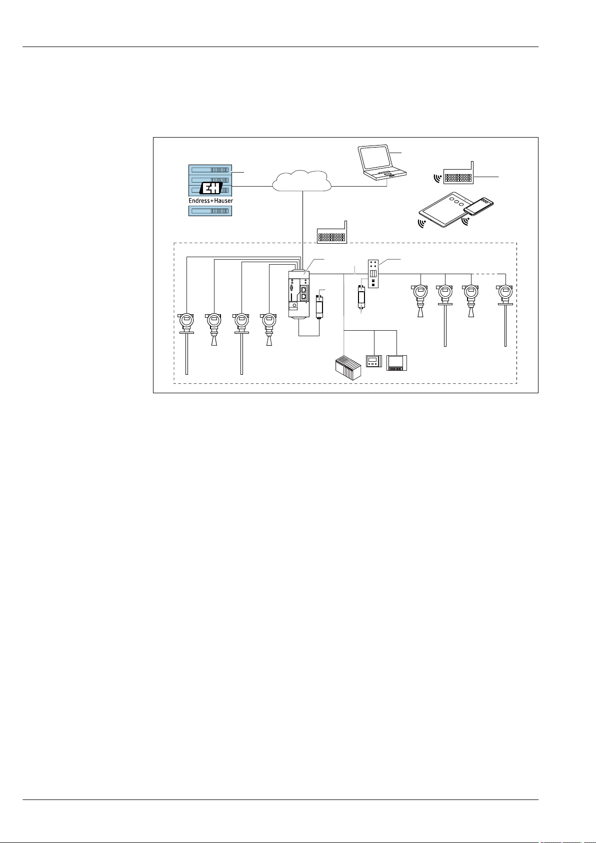
Micropilot FMR51, FMR52
6
.
10
9
1
3
4
6
5 8
7
2
WWW
Cloud-based application: SupplyCare Hosting
SupplyCare Hosting is offered as a hosting service (software as a service). Here, the software is
installed within the Endress+Hauser IT infrastructure and made available to the user in the Endress
+Hauser portal.
A0034289
35 Example of inventory management platform with SupplyCare Hosting SCH30
1 SupplyCare Hosting installation in Endress+Hauser data center
2 PC workstation with Internet connection
3 Warehouse locations with Internet connection via 2G/3G with FXA42 or FXA30
4 Warehouse locations with Internet connection with FXA42
5 Fieldgate FXA42
6 Power supply 24 V DC
7 Modbus TCP via Ethernet as server/client
8 Converter from Modbus to HART Multidrop
9 HART Multidrop
10 4 x 4 to 20 mA analog input (2-wire/4-wire)
With SupplyCare Hosting, users do not need to make the initial software purchase or install and run
the IT infrastructure needed. Endress+Hauser constantly update SupplyCare Hosting and enhance
the capability of the software in conjunction with the customer. The hosted version of SupplyCare is
thus always up-to-date and can be customized to meet different customer requirements. Other
services are also offered in addition to the IT infrastructure and the software that is installed in a
secure, redundant Endress+Hauser data center. These services include defined availability of the
global Endress+Hauser Service and Support Organization and defined response times in a service
event.
88 Endress+Hauser
Page 89
Micropilot FMR51, FMR52
Certificates and approvals
Currently available certificates and approvals can be called up via the product configurator.
CE mark
RoHS
RCM-Tick marking
Ex approval
The measuring system meets the legal requirements of the applicable EC guidelines. These are listed
in the corresponding EC Declaration of Conformity together with the standards applied.
Endress+Hauser confirms successful testing of the device by affixing to it the CE mark.
The measuring system complies with the substance restrictions of the Restriction on Hazardous
Substances Directive 2011/65/EU (RoHS 2).
The supplied product or measuring system meets the ACMA (Australian Communications and Media
Authority) requirements for network integrity, interoperability, performance characteristics as well
as health and safety regulations. Here, especially the regulatory arrangements for electromagnetic
compatibility are met. The products are labelled with the RCM- Tick marking on the name plate.
A0029561
• ATEX
• IEC Ex
• CSA
• FM
• NEPSI
• KC
• INMETRO
• TIIS (in preparation)
Additional safety instructions must be observed for applications in hazardous areas. They are
contained in the separate "Safety Instructions" (XA) document, which is included in the scope of
delivery. Reference is made to the XA on the nameplate of the device.
Details on the available certificats as well as the associated XAs can be found in the Associated
documentation chapter in the Safety instructions section: → 110.
Dual seal according to ANSI/ISA 12.27.01
Functional Safety
WHG
Sanitary compatibility
The devices have been designed according to ANSI/ISA 12.27.01 as dual seal devices, allowing the
user to waive the use and save the cost of installing external secondary process seals in the conduit
as required by the process sealing sections of ANSI/NFPA 70 (NEC) and CSA 22.1 (CEC) These
instruments comply with the North-American installation practice and provide a very safe and costsaving installation for pressurized applications with hazardous fluids.
Further information can be found in the Safety Instructions (XA) of the relevant devices.
Used for level monitoring (MIN, MAX, range) up to SIL 3 (homogeneous or inhomogeneous
redundancy), independently assessed by TÜV Rhineland as per IEC 61508. Other information see
documentation SD01087F: "Functional Safety Manual".
WHG approval: Z-65.16-524
FMR52 with flange cladding made of PTFE conforms to FDA 21 CFR 177.1550 and USP <88> Class
VI
Endress+Hauser 89
Page 90
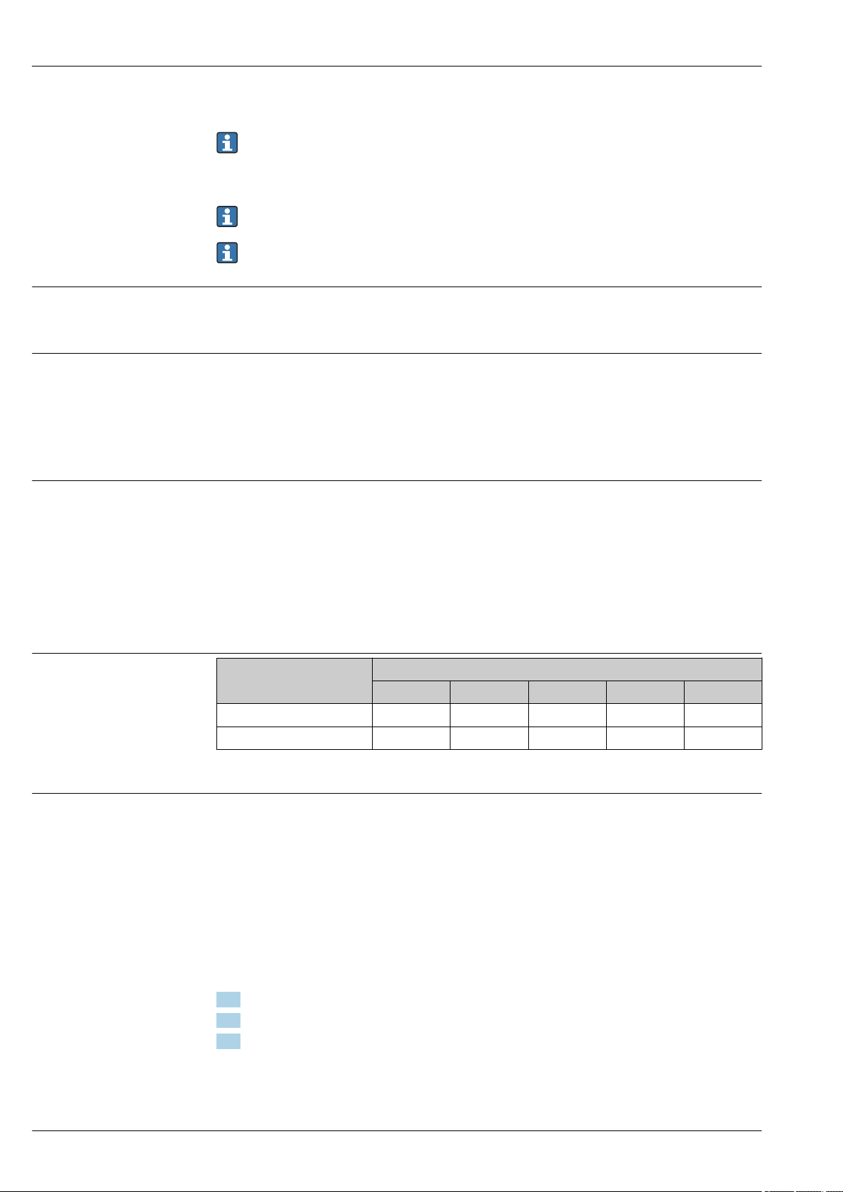
Micropilot FMR51, FMR52
3A and EHEDG approval with Tri-Clamp and DIN11851 process connection.
To avoid risk of contamination, install according to the “Hygienic Equipment Design Criteria
(HDC)” as stated in the Subgroup Design Principles of the EHEDG, Doc. 8 from April 2004.
Suitable fittings and seals must be used to ensure hygiene-compliant design according to the
specifications of 3-A SSI and EHEDG.
The leak-tight connections can be cleaned with the cleaning methods usually used in this
industry without leaving residues.
The 316L housing (GT18), option B in the order attribute 40, is not suitable for applications
which need a 3A approval.
NACE MR 0175 / ISO 15156
NACE MR 0103
Pressure equipment with
allowable pressure
≤ 200 bar (2 900 psi)
Marine certificate
For FMR51 and FMR54:
• The wetted, metallic materials comply with the requirements of NACE MR 0175 / ISO 15156.
• Declaration of conformity: see product structure, feature 580, option JB.
For FMR51 and FMR54:
• The wetted, metallic materials comply with the requirements of NACE MR 0103.
• The certificate of compliance is based on NACE MR 0175.
The hardness and the intercrystalline corrision have been tested, as well as the heat treatment
(solution annealed) has been carried out. The used materials comply therefore with the
requirements of NACE MR 0103.
• Declaration of conformity: see product structure, feature 580, option JE.
Pressure instruments with a flange and threaded boss that do not have a pressurized housing do not
fall within the scope of the Pressure Equipment Directive, irrespective of the maximum allowable
pressure.
Reasons:
According to Article 2, point 5 of EU Directive 2014/68/EU, pressure accessories are defined as
"devices with an operational function and having pressure-bearing housings".
If a pressure instrument does not have a pressure-bearing housing (no identifiable pressure chamber
of its own), there is no pressure accessory present within the meaning of the Directive.
Device Marine certificate
GL ABS LR BV DNV
FMR51
FMR52
1)
1) see oredering feature 590 "Additional approval"
Radio standard EN302729-1/2
The devices Micropilot FMR50, FMR51, FMR52, FMR56 and FMR57 are conform with the LPR
(Level Probing Radar) standard EN302729-1/2. The devices are allowed to be used inside or outside
of closed bins or tanks in countries of th EU and the EFTA. Precondition is that the country itself
already has implemented the directive.
At present, the following countries have already implemented the directive:
Belgium, Bulgaria, Germany, Denmark, Estonia, France, Greece, Great Britain, Ireland, Iceland, Italy,
Liechtenstein, Lithuania, Latvia, Malta, Netherland, Norway, Austria, Poland, Romania, Sweden,
Switzerland, Slovakia, Spain, Czech Republic and Cyprus.
All countries not mentioned above are at present in the implementation phase.
For the use of the devices outside of closed bins or tanks, the following has to be observed:
1. The installation has to be done by trained personnel.
2. The antenna of the device has to be mounted on a fixed place and vertically to the bottom.
3. The mounting place has to be in a distance of at least 4 km to the mentioned astronomical
stations or an appropriate permission has to be issued by the national authority. If the device is
mounted at a distance of 4 to 40 km from the stations mentioned, the maximum mounting
height is restricted to 15 m (49 ft).
90 Endress+Hauser
Page 91
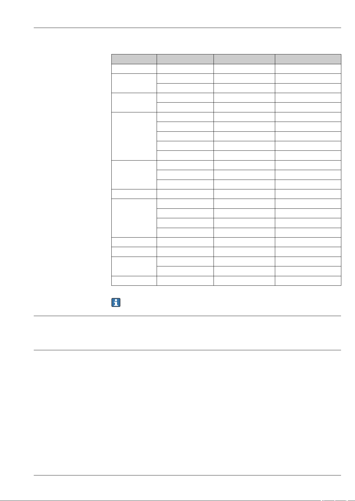
Micropilot FMR51, FMR52
Astronomical stations
Country Name of the station Geographical latitude Geographical longitude
Germany Effelsberg 50°31'32" N 06°53'00" E
Finland Metsähovi 60°13'04" N 24°23'37" E
Tuorla 60°24'56" N 24°26'31" E
France Plateau de Bure 44°38'01" N 05°54'26" E
Floirac 44°50'10" N 00°31'37" W
United Kingdom Cambridge 52°09'59" N 00°02'20" E
Damhall 53°09'22" N 02°32'03" W
Jodrell Bank 53°14'10" N 02°18'26" W
Knockin 52°47'24" N 02°59'45" W
Pickmere 53°17'18" N 02°26'38" W
Italy Medicina 44°31'14" N 11°38'49" E
Noto 36°52'34" N 14°59'21" E
Sardinia 39°29'50" N 09°14'40" E
Poland Krakow Fort Skala 50°03'18" N 19°49'36" E
Russia Dmitrov 56°26'00" N 37°27'00" E
Kalyazin 57°13'22" N 37°54'01" E
Pushchino 54°49'00" N 37°40'00" E
Zelenchukskaya 43°49'53" N 41°35'32" E
Sweden Onsala 57°23'45" N 11°55'35" E
Switzerland Bleien 47°20'26" N 08°06'44" E
Spain Yebes 40°31'27" N 03°05'22" W
Robledo 40°25'38" N 04°14'57" W
Hungary Penc 47°47'22" N 19°16'53" E
Radio standard EN302372-1/2
FCC / Industry Canada
In general the requirements of EN 302729-1/2 have to be taken in consideration.
The devices Micropilot FMR50, FMR51, FMR52, FMR53, FMR54, FMR56 and FMR57 are conform
with the TLPR (Tanks Level Probing Radar) standard EN302372-1/2 and can always be used in
closed tanks or bins. For installation, points a to f in Annex B of EN302372-1 have to be taken into
account.
This device complies with Part 15 of the FCC rules. Operation is subject to the following two
conditions: (1) This device may not cause harmful interference, and (2) this device must accept any
interference received, including interference that may cause undesired operation.
Canada CNR-Gen Section 7.1.3
This device complies with Industry Canada licence-exempt RSS standard(s). Operation is subject to
the following two conditions: (1) This device may not interference, and (2) this device must accept
any interference, including interference that may cause undesired operation of the device.
Le présent appareil est conforme aux CNR d'Industrie Canada applicables aux appareils radio exempts
de licence. L'exploitation est autorisée aux deux conditions suivantes : (1) l'appareil ne doit pas
produire de brouillage, et (2) l'utilisateur de l'appareil doit accepter tout brouillage radioélectrique
subi, même si le brouillage est susceptible d'en compromettre le fonctionnement.
[Any] changes or modifications not expressly approved by the party responsible for compliance could
void the user's authority to operate the equipment.
Endress+Hauser 91
Page 92

Micropilot FMR51, FMR52
Japanese radio approval
CRN approval
In addition, the devices FMR50
8)
, FMR51
9)
, FMR52
10)
, FMR56 and FMR57 are compliant with the
LPR (Level probe radar) regulation also for free space applicactions according to the FCC Code of
Federal Regulations, CFR 47, Part 15, Sections 15.205, 15.207, 15.209, 15.256 for antenna sizes
bigger than 50 mm (2.0 in)
11)
. For these applications the devices must be professionally installed in
a downward operating position. In addition, the devices are not allowed to be mounted in a zone of
4 km around RAS stations and within a radius of 40 km around RAS stations the maxium operation
height of devices is 15 m (49 ft) above ground.
The devices FMR50, FMR51, FMR52, FMR54 and FMR57 comply with the Japanese Radio Law,
Article 6, Section 1(1).
Some device versions have a CRN approval. Devices are CRN approved if the folowing two conditions
are met:
• The device has a CSA approval (Product structure: Feature 010 "Approval")
• The device has a CRN approved process connection according to the following table.
Feature 100 of the product structure Process connection
AFJ NPS 2" Cl.150 RF, 316/316L
AFK NPS 2" Cl.150, PTFE >316/316L
AFM NPS 2" Cl.150, AlloyC >316/316L
AGJ NPS 3" Cl.150 RF, 316/316L
AGK NPS 3" Cl.150, PTFE >316/316L
AGM NPS 3" Cl.150, AlloyC >316/316L
AHJ NPS 4" Cl.150 RF, 316/316L
AHK NPS 4" Cl.150, PTFE >316/316L
AHM NPS 4" Cl.150, AlloyC >316/316L
AJJ NPS 6" Cl.150 RF, 316/316L
AJK NPS 6" Cl.150, PTFE >316/316L
AJM NPS 6" Cl.150, AlloyC >316/316L
ARJ NPS 2" Cl.300 RF, 316/316L
ARM NPS 2" Cl.300, AlloyC >316/316L
ASJ NPS 3" Cl.300 RF, 316/316L
ASM NPS 3" Cl.300, AlloyC >316/316L
ATJ NPS 4" Cl.300 RF, 316/316L
ATM NPS 4" Cl.300, AlloyC >316/316L
MRK DIN11851 DN50 PN25 slotted nut, PTFE>316L
MTK DIN11851 DN80 PN25 slotted nut, PTFE>316L
RGJ Thread ANSI MNPT1-1/2, 316L
RVJ Thread EN10226 R1-1/2, 316L
TDJ Tri-Clamp ISO2852 DN40-51 (2"), 316L
TDK Tri-Clamp ISO2852 DN40-51 (2"), PTFE>316L, 3A, EHEDG
TFJ Tri-Clamp ISO2852 DN70-76.1 (3"), 316L
8) Except of FMR50-######BM* (Horn 40mm/1-1/2", PVDF encapsulated)
9) Except for FMR51-######BA* (Horn 40mm/1-1/2") and FMR51-######BB* (Horn 50mm/2")
10) Except for FMR52-######BO* (Horn 50mm/2", flush mount)
11)
92 Endress+Hauser
Page 93
Micropilot FMR51, FMR52
Feature 100 of the product structure Process connection
TFK Tri-Clamp ISO2852 DN70-76.1 (3"), PTFE>316L, 3A, EHEDG
THK Tri-Clamp ISO2852 DN101.6 (4"), PTFE>316L, 3A, EHEDG
• Process connections without CRN approval are not included in this table.
• Refer to the product structure to see which process connections are available for a specific
device type.
• For some process connections not listed in the product structure a CRN approval is available
on request.
• CRN approved devices are marked with the registration number OF15872.5C on the
nameplate.
For device versions listed in the table below, the maximum allowed pressure is reduced if they
have a CRN approval. For device versions not listed in the table below the pressure range as
indicated in the "Process" chapter → 60 is not affected by the CRN approval.
Track record
Product Antenna
FMR52 TFK: Tri-Clamp 3" 10 bar (145 psi)
FMR51 D2: Graphite (HT) 100 bar (1 450 psi)
1) Feature 070 of the product structure
2) Feature 100 of the product structure
3) Feature 090 of the product structure
1)
Process connection
THK: Tri-Clamp 4" 10 bar (145 psi)
2)
Seal
3)
max. pressure
FMR5x is the upgrade model of the corresponding FMR2xx series.
Endress+Hauser 93
Page 94
Micropilot FMR51, FMR52
Test, Certificate
Feature 580
"Test,
Certificate"
JA 3.1 Material certificate, wetted metallic parts, EN10204-3.1 inspection
JB Conformity to NACE MR0175, wetted metallic parts FMR51
JD 3.1 Material certificate, pressurized parts, EN10204-3.1 inspection
JE Conformity to NACE MR0103, wetted metallic parts FMR51
JF Conformity to AD2000, wetted metallic parts:
KD Helium leak test, internal procedure, inspection certificate FMR51
KE Pressure test, internal procedure, inspection certificate • FMR51
KG 3.1 Material certificate+PMI test (XRF), internal procedure, wetted metallic
KP Liquid penetrant test AD2000-HP5-3(PT), wetted/pressurized metallic
KQ Liquid penetrant test ISO23277-1 (PT), wetted/pressurized metallic parts,
KR Liquid penetrant test ASME VIII-1 (PT), wetted/pressurized metallic parts,
KS Welding documentation, wetted/pressurized seams
KV Conformity to ASME B31.3:
Designation Available for
FMR51
certificate
FMR52
certificate
• FMR51
Material of all wetted/pressurized parts conform to AD2000 (Technical
rules W2, W9, W10)
parts, EN10204-3.1 inspection certificate
parts, inspection certificate
inspection certificate
inspection certificate
consisting of
• Drawing
• WPQR (Welding Procedure Qualification Report)
• WPS (Welding Process Specification)
• Manufacturer Declaration
The dimensions, materials of construction, pressure / temperature ratings
and identification markings of the device comply with the requirements of
ASME B31.3
• FMR52
• FMR52
• FMR51
• FMR52
FMR51
FMR51
FMR51
FMR51
• FMR51
• FMR52
Test reports, declarations and material test certificates can be obtained electronically from the
W@M Device Viewer :
Enter the serial number from the nameplate (www.endress.com/deviceviewer)
This applies to the options of the following ordering features:
• 550 "Calibration"
• 580 "Test, Certificate"
• 590 "Additional Approval", option LW: "CoC-ASME BPE"
Product documentation on paper
Test reports, declarations and material certificates can be ordered as hardcopies via ordering feature
570 "Service", option I7 „Product documentation on paper“. The printouts will be enclosed in the
product delivery.
94 Endress+Hauser
Page 95

Micropilot FMR51, FMR52
Other standards and guidelines
• EN 60529
Degrees of protection by housing (IP code)
• EN 61010-1
Protection Measures for Electrical Equipment for Measurement, Control, Regulation and
Laboratory Procedures.
• IEC/EN 61326
"Emission in accordance with Class A requirements". Electromagnetic compatibility (EMC
requirements)
• NAMUR NE 21
Electromagnetic compatibility (EMC) of industrial process and laboratory control equipment.
• NAMUR NE 43
Standardization of the signal level for the breakdown information of digital transmitters with
analog output signal.
• NAMUR NE 53
Software of field devices and signal-processing devices with digital electronics
• NAMUR NE 107
Status classification as per NE107
• NAMUR NE 131
Requirements for field devices for standard applications
• IEC61508
Functional safety of electrical/electronic/programmable electronic safety-related systems
Endress+Hauser 95
Page 96

Ordering information
Micropilot FMR51, FMR52
Ordering information
Detailed ordering information is available from the following sources:
• In the Product Configurator on the Endress+Hauser website: www.endress.com -> Click "Corporate"
-> Select your country -> Click "Products" -> Select the product using the filters and search field ->
Open product page -> The "Configure" button to the right of the product image opens the Product
Configurator.
• From your Endress+Hauser Sales Center: www.addresses.endress.com
Product Configurator - the tool for individual product configuration
• Up-to-the-minute configuration data
• Depending on the device: Direct input of measuring point-specific information such as
measuring range or operating language
• Automatic verification of exclusion criteria
• Automatic creation of the order code and its breakdown in PDF or Excel output format
• Ability to order directly in the Endress+Hauser Online Shop
96 Endress+Hauser
Page 97
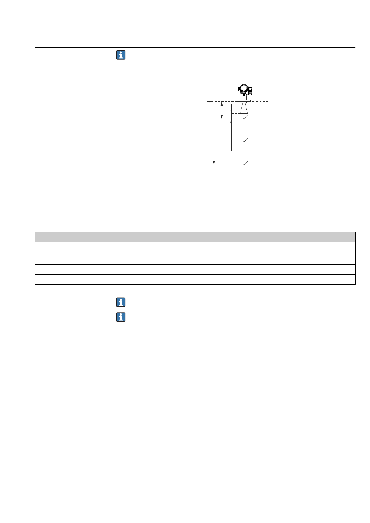
Micropilot FMR51, FMR52
R
A
500 (19.7)
6000 (236)
1
3
2
3-point linearity protocol
The following notes must be taken into account if option F3 ("3 point linearity protocol") has
been selected in feature 550 ("Calibration").
The 3 points of the linearity protocol are defined as follows:
A0023272
36 Points of the 3-point linearity protocol; Dimensions: mm (in)
A Distance from reference point R to first measuring point
R Reference point of the measurement
1 First measuring point
2 Second measuring point (centrally between first and third measuring point)
3 Third measuring point
Measuring point Position
1st measuring point • At the distance A from the reference point
• A = antenne length + antenna extension (if present) + 500 mm (19.7 in)
• Minimum distance: A
2nd measuring point centrally between 1st and 3rd measuring point
3rd measuring point 6 000 mm (236 in) below the reference point, R
= 1 000 mm (39.4 in)
min
The position of the measuring points may vary by ±1 cm (±0.04 in).
The linearity is checked under reference conditions.
Endress+Hauser 97
Page 98
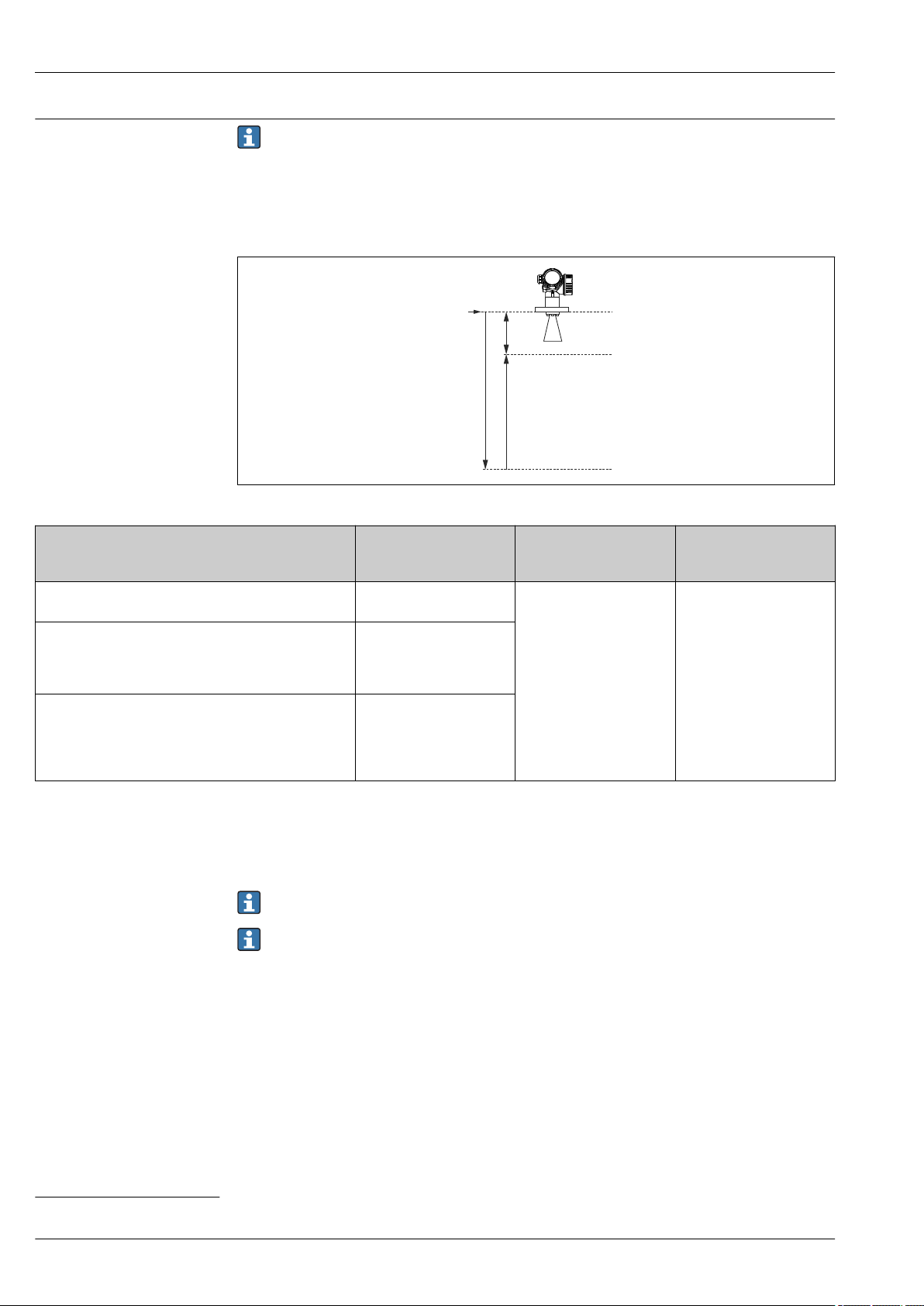
Micropilot FMR51, FMR52
R
A
F
E
5-point linearity protocol
The following notes must be taken into account if option F4 ("5 point linearity protocol") has
been selected in feature 550 ("Calibration").
The five points of the linearity protocol are evenly distributetd across the measuring range (0% to
100%). In order to define the measuring range, Empty calibration (E) and Full calibration (F) have
to be specified
12)
.
The following restrictions have to be taken into account when defining E and F:
Device version Minimum distance
between reference point
(R) and 100% level
FMR51/FMR52
Without antenna extension
FMR51 with 100 mm/4" antenna extension
FMR51 with varaible antenna extension
3)
2)
A ≥ antenna length +
200 mm (8 in)
A ≥ antenna length +
antenna extension
100 mm (4 in) +
200 mm (8 in)
A ≥ antenna length +
maximum antenna
extension
1 000 mm (40 in)
200 mm (8 in)
1)
A0017983
Minimum span Maximum value for
"Empty calibration"
F ≥ 400 mm (16 in) E ≤ 24 m (79 ft)
4)
+
1) Minimum value: A ≥ 400 mm (16 in)
2) Feature 610 "Accessory Mounted", option OM
3) Feature 610 "Accessory Mounted", option OU or OV
4) This value is independent of the actual size of the antenna extension.
The linearity is checked under reference conditions.
The selected values of Empty calibration and Full calibration are only used to record the
linearity protocol and are reset to their probe specific default values thereafter. If values
different from the default are required, they must be ordered as a customized parametrization
→ 99.
12) If E and F are not specified, probe dependent default values will be used instead.
98 Endress+Hauser
Page 99
Micropilot FMR51, FMR52
Customized parametrization
Tagging (TAG)
If the option IJ "Customized parametrization HART", IK "Customized parametrization PA" or IL
"Customized parametrization FF" has been selected in feature 570 "Service", customer specific
presettings can be selected for the following parameters:
Parameter Communication Selection list / range of
values
Setup → Distance unit • HART
• PA
• FF
Setup → Empty calibration • HART
• PA
• FF
Setup → Full calibration • HART
• PA
• FF
Setup → Adv. Setup → Current output 1/2 → Damping HART 0 to 999.9 s
Setup → Adv. Setup → Current output 1/2 → Failure mode HART • Min
Setup → Adv. Setup → Current output 1/2 → Burst mode HART • Off
Ordering feature 895: Marking
Option Z1: Tagging (TAG), see additional spec.
Position of the measuring
point marking
Definition of the measuring
point designation
Designation in the Electronic
Name Plate (ENP)
Designation on the display
module
To be selected in the additional specifications:
• Tag plate Stainless Steel
• Self-adhesive paper label
• Supplied label/plate
• RFID TAG
• RFID TAG + Tag plate Stainless Steel
• RFID TAG + Self-adhesive paper label
• RFID TAG + Supplied label/plate
To be defined in the additional specifications:
3 lines containing up to 18 characters each
The measuring point designation appears on the selected label and/or the
RFID TAG.
The first 32 characters of the measuring point designation
The first 12 characters of the measuring point designation
• in
• ft
• mm
• m
max. 70 m (230 ft)
max. < 70 m (230 ft)
• Max
• Last valid value
• On
Services
The following services can be selected via the product structure in the Product Configurator
13)
:
• PWIS free (PWIS: paint wetting impairment substances)
• Customized parametrization HART → 99
• Customized parametrization PA→ 99
• Customized parametrization FF → 99
• Without tooling DVD (FieldCare)
13) Feature 570 of the product structure
Endress+Hauser 99
Page 100

Application Packages
Heartbeat Diagnostics Availability
Available in all device versions.
Function
• Continuous self-monitoring of the device.
• Diagnostic messages output to
– the local display.
– an asset management system (e.g. FieldCare/DeviceCare).
– an automation system (e.g. PLC).
Advantages
• Device condition information is available immediately and processed in time.
• The status signals are classified in accordance with VDI/VDE 2650 and NAMUR recommendation
NE 107 and contain information about the cause of the error and remedial action.
Detailed description
See Operating Instructions of the device (→ 110); chapter "Diagnostics and trouble shooting"
Micropilot FMR51, FMR52
100 Endress+Hauser
 Loading...