

Endress+Hauser Micropilot FMR50 Brief Operating Instructions
KA01099F/00/EN/05.18
71394693
2018-04-12
Products Solutions Services
Brief Operating Instructions
Micropilot FMR50
HART
Free space radar
These Instructions are Brief Operating Instructions; they are
not a substitute for the Operating Instructions pertaining to
the device.
Detailed information about the device can be found in the
Operating Instructions and the other documentation:
Available for all device versions via:
– Internet: www.endress.com/deviceviewer
– Smart phone/tablet: Endress+Hauser Operations App
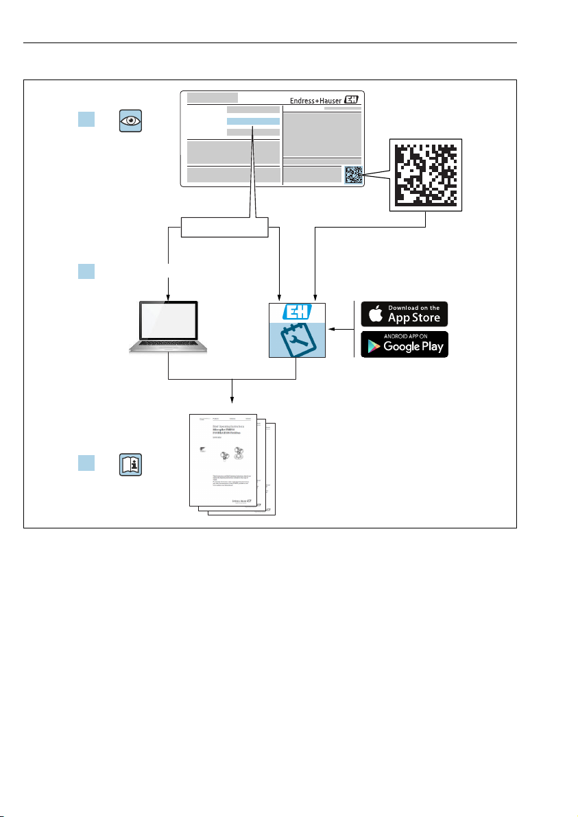
Micropilot FMR50 HART
Order code:
Ext. ord. cd.:
Ser. no.:
www.endress.com/deviceviewer
Endress+Hauser
Operations App
XXXXXXXXXXXX
XXXXX-XXXXXX
XXX.XXXX.XX
Serial number
1.
3.
2.
2 Endress+Hauser
A0023555

Micropilot FMR50 HART Table of contents
Table of contents
1 Wichtige Hinweise zum Dokument ................................................ 4
1.1 Symbols ............................................................................. 4
1.2 Terms and abbreviations ................................................................. 6
1.3 Registered trademarks .................................................................. 7
2 Basic safety instructions .......................................................... 8
2.1 Requirements for the personnel ............................................................ 8
2.2 Designated use ........................................................................ 8
2.3 Workplace safety ...................................................................... 9
2.4 Operational safety ......................................................................9
2.5 Product safety ......................................................................... 9
3 Product description .............................................................. 11
3.1 Product design ....................................................................... 11
4 Incoming acceptance and product identification ................................. 11
4.1 Incoming acceptance ................................................................... 11
4.2 Product identification .................................................................. 12
5 Storage, Transport ............................................................... 13
5.1 Storage conditions .................................................................... 13
5.2 Transport product to the measuring point ................................................... 13
6 Installation ...................................................................... 14
6.1 Installation conditions .................................................................. 14
6.2 Measuring conditions .................................................................. 19
6.3 Installation in vessel (free space) .......................................................... 20
6.4 Installation in stilling well ............................................................... 25
6.5 Installation in bypass .................................................................. 26
6.6 Container with heat insulation ........................................................... 27
6.7 Turning the transmitter housing .......................................................... 27
6.8 Turning the display .................................................................... 28
6.9 Post-installation check ................................................................. 30
7 Electrical connection ............................................................ 31
7.1 Connection conditions .................................................................. 31
7.2 Connecting the measuring device ......................................................... 45
7.3 Post-connection check ..................................................................49
8 Commissioning via SmartBlue (app) ............................................. 49
8.1 Requirements ........................................................................ 49
8.2 Commissioning ....................................................................... 50
9 Commissioning via wizard ....................................................... 54
10 Commissioning (via operating menu) ............................................ 55
10.1 Display and operating module ............................................................ 55
10.2 Operating menu ...................................................................... 58
10.3 Unlock the device ..................................................................... 59
10.4 Setting the operating language ........................................................... 59
10.5 Configuration of a level measurement ...................................................... 60
10.6 User-specific applications ............................................................... 61
Endress+Hauser 3
Wichtige Hinweise zum Dokument Micropilot FMR50 HART
DANGER
WARNING
CAUTION
NOTICE
1 Wichtige Hinweise zum Dokument
1.1 Symbols
1.1.1 Safety symbols
Symbol Meaning
DANGER!
This symbol alerts you to a dangerous situation. Failure to avoid this situation will result in
serious or fatal injury.
WARNING!
This symbol alerts you to a dangerous situation. Failure to avoid this situation can result in
serious or fatal injury.
CAUTION!
This symbol alerts you to a dangerous situation. Failure to avoid this situation can result in
minor or medium injury.
NOTE!
This symbol contains information on procedures and other facts which do not result in
personal injury.
1.1.2 Electrical symbols
Symbol Meaning Symbol Meaning
Direct current Alternating current
Direct current and alternating current Ground connection
Symbol Meaning
Protective Earth (PE)
A terminal which must be connected to ground prior to establishing any other connections.
The ground terminals are situated inside and outside the device:
• Inner ground terminal: Connects the protectiv earth to the mains supply.
• Outer ground terminal: Connects the device to the plant grounding system.
A grounded terminal which, as far as
the operator is concerned, is grounded
via a grounding system.
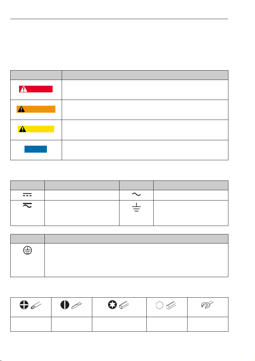
1.1.3 Tool symbols
Flat blade
screwdriver
A0011220
A0013442 A0011221
Torx screwdriver Allen key Hexagon wrench
A0011219
Cross-head
screwdriver
4 Endress+Hauser
A0011222

Micropilot FMR50 HART Wichtige Hinweise zum Dokument
A
1.
1.
-
.
1.1.4 Symbols for certain types of information
Symbol Meaning Symbol Meaning
Permitted
Procedures, processes or actions that
are permitted.
Forbidden
Procedures, processes or actions that
are forbidden.
Reference to documentation.
Preferred
Procedures, processes or actions that
are preferred.
Tip
Indicates additional information.
Reference to page.
Reference to graphic.
Result of a step. Visual inspection.
1.1.5 Symbols in graphics
Symbol Meaning
1, 2, 3 ... Item numbers
, 2., 3.… Series of steps
A, B, C, ... Views
A-A, B-B, C-C, ... Sections
Hazardous area
Indicates a hazardous area.
Safe area (non-hazardous area)
Indicates the non-hazardous area.
1.1.6 Symbols at the device
Symbol Meaning
Safety instructions
Observe the safety instructions contained in the associated Operating Instructions.
Temperature resistance of the connection cables
Specifies the minimum value of the temperature resistance of the connection cables.
, 2., 3.… Series of steps.
Endress+Hauser 5

Wichtige Hinweise zum Dokument Micropilot FMR50 HART
1.2 Terms and abbreviations
Term/abbreviation Explanation
BA Document type "Operating Instructions"
KA Document type "Brief Operating Instructions"
TI Document type "Technical Information"
SD Document type "Special Documentation"
XA Document type "Safety Instructions"
PN Nominal pressure
MWP Maximum Working Pressure
ToF Time of Flight
FieldCare Scalable software tool for device configuration and integrated plant asset management solutions
DeviceCare Universal configuration software for Endress+Hauser HART, PROFIBUS, FOUNDATION Fieldbus
DTM Device Type Manager
DD Device Description for HART communication protocol
εr (DC value) Relative dielectric constant
Operating tool The term "operating tool" is used in place of the following operating software:
BD Blocking Distance; no signals are analyzed within the BD.
PLC Programmable Logic Controller
CDI Common Data Interface
PFS Pulse Frequence Status (Switching output)
The MWP can also be found on the nameplate.
and Ethernet field devices
• FieldCare / DeviceCare, for operation via HART communication and PC
• SmartBlue (app), for operation using an Android or iOS smartphone or tablet.
6 Endress+Hauser

Micropilot FMR50 HART Wichtige Hinweise zum Dokument
1.3 Registered trademarks
®
HART
Registered trademark of the FieldComm Group, Austin, USA
Bluetooth®
The Bluetooth® word mark and logos are registered trademarks owned by the Bluetooth SIG,
Inc. and any use of such marks by Endress+Hauser is under license. Other trademarks and
trade names are those of their respective owners.
Apple®
Apple, the Apple logo, iPhone, and iPod touch are trademarks of Apple Inc., registered in the
U.S.and other countries. App Store is a service mark of Apple Inc.
Android®
Android, Google Play and the Google Play logo are trademarks of Google Inc.
KALREZ®, VITON
Registered trademark of DuPont Performance Elastomers L.L.C., Wilmington, USA
TEFLON
®
Registered trademark of E.I. DuPont de Nemours & Co., Wilmington, USA
TRI CLAMP
Registered trademark of Alfa Laval Inc., Kenosha, USA
®
®
Endress+Hauser 7

Basic safety instructions Micropilot FMR50 HART
2 Basic safety instructions
2.1 Requirements for the personnel
The personnel must fulfill the following requirements for its tasks:
Trained, qualified specialists must have a relevant qualification for this specific function
‣
and task.
Are authorized by the plant owner/operator.
‣
Are familiar with federal/national regulations.
‣
Before starting work, read and understand the instructions in the manual and
‣
supplementary documentation as well as the certificates (depending on the application).
Follow instructions and comply with basic conditions.
‣
2.2 Designated use
Application and measured materials
The measuring device described in these Operating Instructions is intended for the
continuous, contactless level measurement of liquids, pastes and sludge. The device can also
be freely mounted outside closed metal vessels (e.g. above basins, open channels or open
piles) because of its operating frequency of about 26 GHz, a maximum radiated pulsed power
of 5.7 mW and an average power output of 0.015 mW (for the version with advanced
dynamics: maximum pulse power: 23.3 mW; average power: 0.076 mW). Operation is
completely harmless to humans and animals.
Observing the limit values specified in the "Technical data" and listed in the Operating
Instructions and supplementary documentation, the measuring device may be used for the
following measurements only:
Measured process variables: level, distance, signal strength
‣
Calculated process variables: Volume or mass in arbitrarily shaped vessels; flow through
‣
measuring weirs or flumes (calculated from the level by the linearization functionality)
To ensure that the measuring device remains in proper condition for the operation time:
Use the measuring device only for measured materials against which the process-wetted
‣
materials are adequately resistant.
Observe the limit values in "Technical data".
‣
Incorrect use
The manufacturer is not liable for damage caused by improper or non-designated use.
Verification for borderline cases:
For special measured materials and cleaning agents, Endress+Hauser is glad to provide
‣
assistance in verifying the corrosion resistance of wetted materials, but does not accept any
warranty or liability.
Residual risk
The electronics housing and its built-in components such as display module, main electronics
module and I/O electronics module may heat to 80 °C (176 °F) during operation through heat
transfer from the process as well as power dissipation within the electronics. During operation
the sensor may assume a temperature near the temperature of the measured material.
8 Endress+Hauser

Micropilot FMR50 HART Basic safety instructions
Danger of burns due to heated surfaces!
For high process temperatures: Install protection against contact in order to prevent burns.
‣
2.3 Workplace safety
For work on and with the device:
Wear the required personal protective equipment according to federal/national
‣
regulations.
2.4 Operational safety
Risk of injury.
Operate the device in proper technical condition and fail-safe condition only.
‣
The operator is responsible for interference-free operation of the device.
‣
Conversions to the device
Unauthorized modifications to the device are not permitted and can lead to unforeseeable
dangers.
If, despite this, modifications are required, consult with the manufacturer.
‣
Repair
To ensure continued operational safety and reliability,
Carry out repairs on the device only if they are expressly permitted.
‣
Observe federal/national regulations pertaining to repair of an electrical device.
‣
Use original spare parts and accessories from the manufacturer only.
‣
Hazardous area
To eliminate a danger for persons or for the facility when the device is used in the hazardous
area (e.g. explosion protection, pressure vessel safety):
Based on the nameplate, check whether the ordered device is permitted for the intended
‣
use in the hazardous area.
Observe the specifications in the separate supplementary documentation that is an integral
‣
part of these Instructions.
2.5 Product safety
This measuring device is designed in accordance with good engineering practice to meet stateof-the-art safety requirements, has been tested, and left the factory in a condition in which it
is safe to operate. It meets general safety standards and legal requirements.
NOTICE
Loss of degree of protection by opening of the device in humid environments
If the device is opened in a humid environment, the degree of protection indicated on the
‣
nameplate is no longer valid. This may also impair the safe operation of the device.
2.5.1 CE mark
The measuring system meets the legal requirements of the applicable EC guidelines. These are
listed in the corresponding EC Declaration of Conformity together with the standards applied.
Endress+Hauser 9

Basic safety instructions Micropilot FMR50 HART
Endress+Hauser confirms successful testing of the device by affixing to it the CE mark.
2.5.2 EAC conformity
The measuring system meets the legal requirements of the applicable EAC guidelines. These
are listed in the corresponding EAC Declaration of Conformity together with the standards
applied.
Endress+Hauser confirms successful testing of the device by affixing to it the EAC mark.
10 Endress+Hauser
Micropilot FMR50 HART Product description
1 1 6
1
2 4 4
3 5
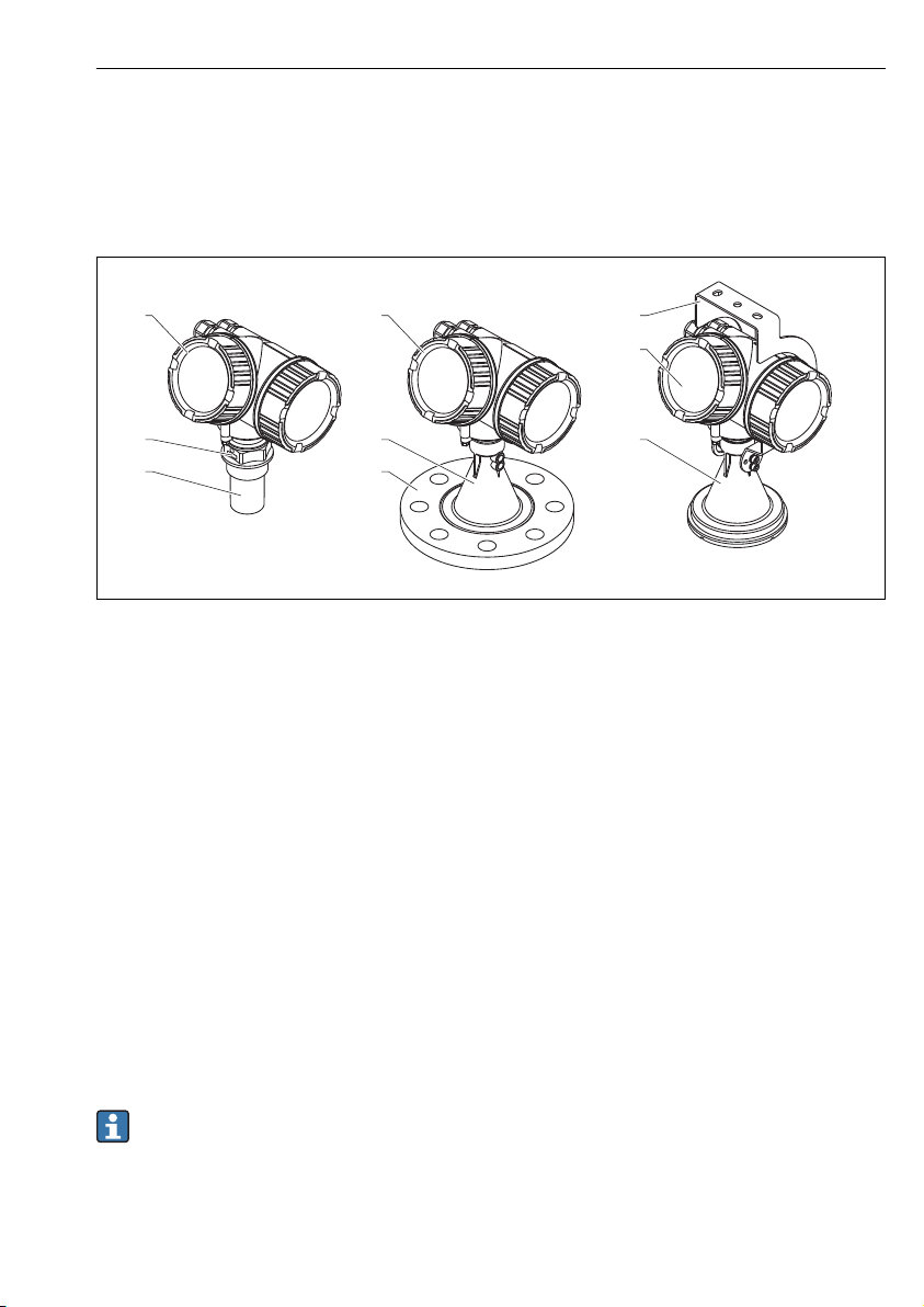
3 Product description
3.1 Product design
3.1.1 Micropilot FMR50
A0016784
1 Design of the Micropilot FMR50 (26 GHz)
1 Electronics housing
2 Process connection (Thread)
3 Horn antenna 40 mm (1-1/2 in), PVDF encapsulated
4 Horn antenna 80mm/100 mm (3in/4 in), PP cladded
5 Slip-on flange
6 Mounting bracket
4 Incoming acceptance and product identification
4.1 Incoming acceptance
Upon receipt of the goods check the following:
• Are the order codes on the delivery note and the product sticker identical?
• Are the goods undamaged?
• Do the nameplate data match the ordering information on the delivery note?
• Is the DVD with the operating tool present?
If required (see nameplate): Are the Safety Instructions (XA) present?
If one of these conditions is not satisfied, contact your Endress+Hauser Sales Center.
Endress+Hauser 11
Incoming acceptance and product identification Micropilot FMR50 HART
Order code:
Ext. ord. cd.:
Ser. no.:
Order code:
Ext. ord. cd.:
Ser. no.:
1
2
3
4
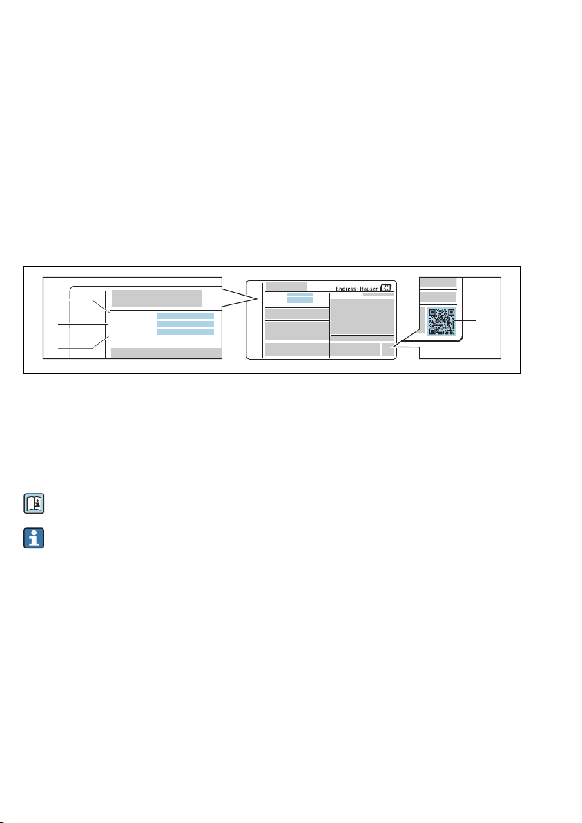
4.2 Product identification
The following options are available for identification of the measuring device:
• Nameplate specifications
• Extended order code with breakdown of the device features on the delivery note
• Enter serial numbers from nameplates in W@M Device Viewer
( www.endress.com/deviceviewer ): All information about the measuring device is
displayed.
• Enter the serial number from the nameplates into the Endress+Hauser Operations App or
scan the 2-D matrix code (QR code) on the nameplate with the Endress+Hauser Operations
App: all the information for the measuring device is displayed.
4.2.1 Nameplate
A0030196
2 Example of a nameplate
1 Order code
2 Serial number (Ser. no.)
3 Extended order code (Ext. ord. cd.)
4 2-D matrix code (QR code)
For detailed information about interpreting the nameplate specifications, refer to the
Operating Instructions for the device.
Only 33 digits of the extended order code can be indicated on the nameplate. If the
extended order code exceeds 33 digits, the rest will not be shown. However, the complete
extended order code can be viewed in the operating menu of the device: Extended order
code 1 to 3 parameter
12 Endress+Hauser
Micropilot FMR50 HART Storage, Transport
5 Storage, Transport
5.1 Storage conditions
• Permitted storage temperature: –40 to +80 °C (–40 to +176 °F)
• Use the original packaging.
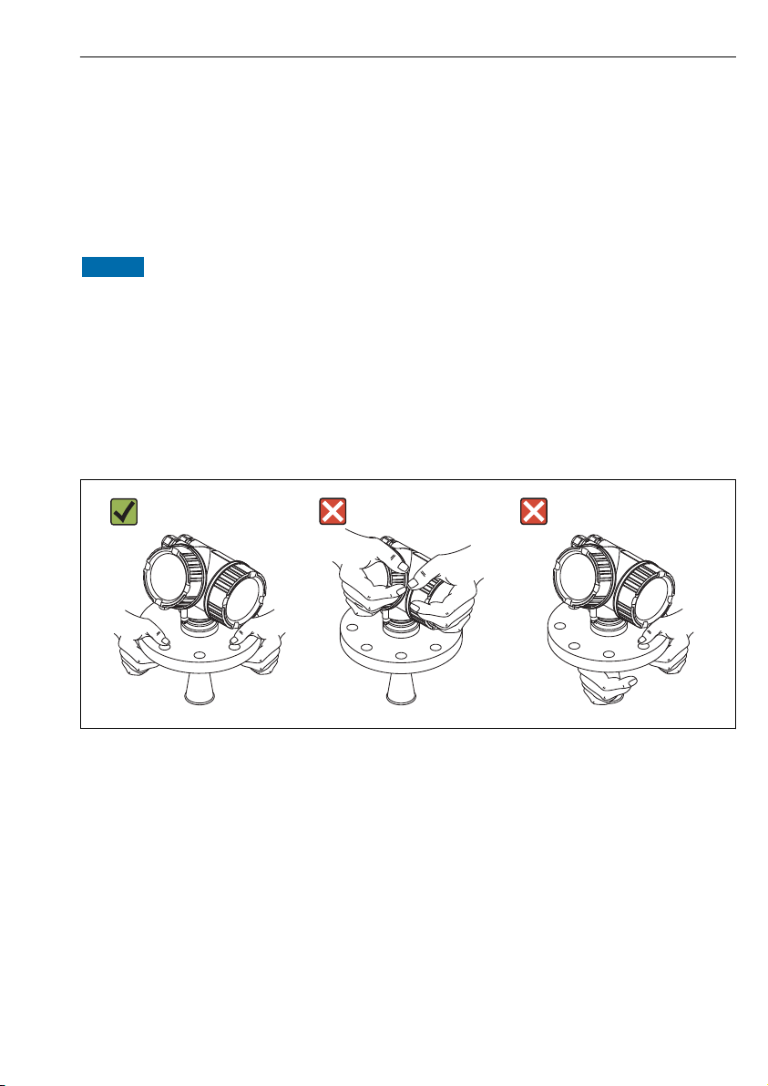
5.2 Transport product to the measuring point
NOTICE
Housing or antenna horn may be damaged or break away.
Risk of injury!
Transport the measuring device to the measuring point in its original packaging or at the
‣
process connection.
Do not fasten lifting devices (hoisting slings, lifting eyes etc.) at the housing or the antenna
‣
horn but at the process connection. Take into account the mass center of the device in
order to avoid unintended tilting.
Comply with the safety instructions, transport conditions for devices over 18kg (39.6lbs)
‣
(IEC61010).
A0016875
Endress+Hauser 13
Installation Micropilot FMR50 HART
A
1 2 3
6 Installation
6.1 Installation conditions
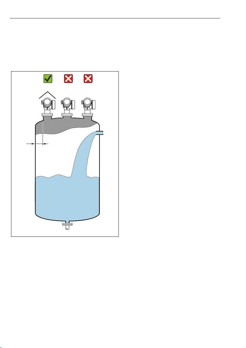
6.1.1 Mounting position
• Recommended distance A from wall
to outer edge of nozzle: ~ 1/6 of tank
diameter.
Nevertheless the device should not be
installed closer than 15 cm (5.91 in)
to the tank wall.
• Not in the center (2), as interference
can cause signal loss.
• Not above the fill stream (3).
• It is recommended to us a weather
protection cover (1) in order to protect
the device from direct sun or rain.
A0016882
14 Endress+Hauser
Micropilot FMR50 HART Installation
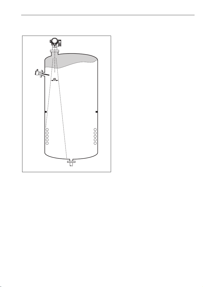
6.1.2 Vessel installations
Avoid any installations (point level
switches, temperature sensors, braces,
vacuum rings, heating coils, baffles etc.)
inside the signal beam. Take into
account the beam angle → 18.
A0018944
Endress+Hauser 15
Installation Micropilot FMR50 HART
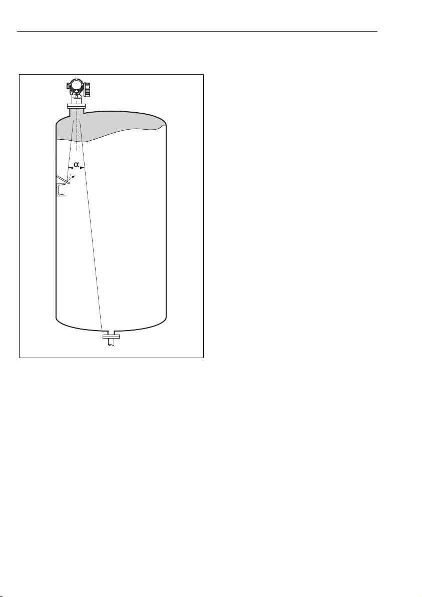
6.1.3 Reduction of interference echoes
Metallic screens mounted at a slope
spread the radar signal and can,
therefore, reduce interference echoes.
A0016890
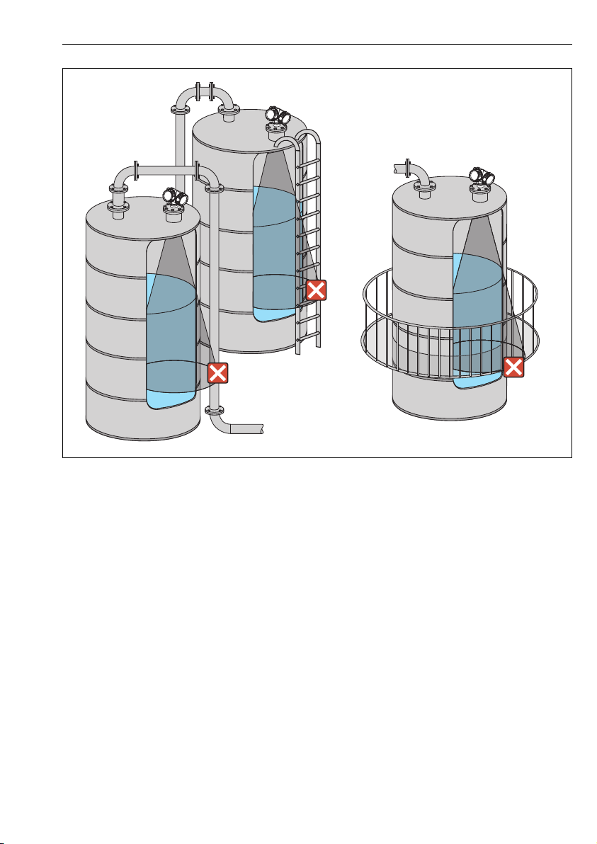
6.1.4 Measurement in a plastic vessel
If the outer wall of the vessel is made of a non-conductive material (e.g. GRP), microwaves can
also be reflected off interfering installations outside the vessel (e.g. metallic pipes (1), ladders
(2), grates (3), ...). Therefore, there should be no such interfering installations in the signal
beam. Please contact Endress+Hauser for further information.
16 Endress+Hauser
Micropilot FMR50 HART Installation
2
3
1
A0017123
6.1.5 Optimization options
• Antenna size
The bigger the antenna, the smaller the beam angle α and the fewer interference echoes
→ 18.
• Mapping
The measurement can be optimized by means of electronic suppression of interference
echoes.
• Antenna alignment
Take into account the marker on the flange or threaded connection → 20 → 22.
• Stilling well
A stilling well can be applied to avoid interferences → 25.
• Metallic screens mounted at a slope
They spread the radar signals and can, therefore, reduce interference echoes.
Endress+Hauser 17
Installation Micropilot FMR50 HART
a
D
W
a
D
_
=
2
2
. .
tan
W
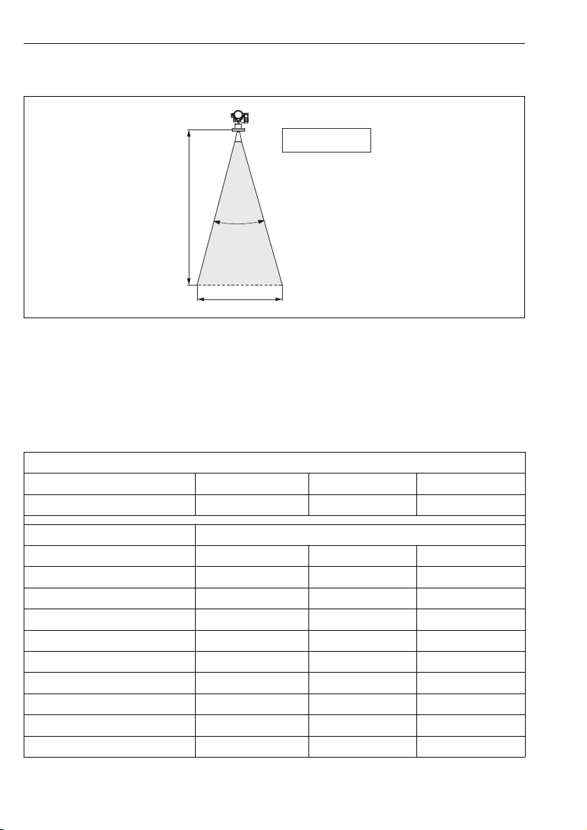
6.1.6 Beam angle
A0016891
3 Relationship between beam angle α, distance D and beamwidth diameter W
The beam angle is defined as the angle α where the energy density of the radar waves reaches
half the value of the maximum energy density (3-dB-width). Microwaves are also emitted
outside the signal beam and can be reflected off interfering installations.
Beam diameter W as a function of beam angle α and measuring distance D:
FMR50
Antenna size 40 mm (1½ in) 80 mm (3 in) 100 mm (4 in)
Beam angle α 23° 10° 8°
Measuring distance (D) Beamwidth diameter W
3 m (9.8 ft) 1.22 m (4 ft) 0.53 m (1.7 ft) 0.42 m (1.4 ft)
6 m (20 ft) 2.44 m (8 ft) 1.05 m (3.4 ft) 0.84 m (2.8 ft)
9 m (30 ft) 3.66 m (12 ft) 1.58 m (5.2 ft) 1.26 m (4.1 ft)
12 m (39 ft) 4.88 m (16 ft) 2.1 m (6.9 ft) 1.68 m (5.5 ft)
15 m (49 ft) 6.1 m (20 ft) 2.63 m (8.6 ft) 2.10 m (6.9 ft)
20 m (66 ft) 8.14 m (27 ft) 3.50 m (11 ft) 2.80 m (9.2 ft)
25 m (82 ft) 10.17 m (33 ft) 4.37 m (14 ft) 3.50 m (11 ft)
30 m (98 ft) - 5.25 m (17 ft) 4.20 m (14 ft)
18 Endress+Hauser
35 m (115 ft) - 6.12 m (20 ft) 4.89 m (16 ft)
40 m (131 ft) - 7.00 m (23 ft) 5.59 m (18 ft)

Micropilot FMR50 HART Installation
6.2 Measuring conditions
• In case of boiling surfaces, bubbling or tendency for foaming use FMR53 or FMR54.
Depending on its consistence, foam can either absorb microwaves or reflect them off the
foam surface. Measurement is possible under certain conditions. For FMR50, FMR51 and
FMR52, the additional option "Advanced dynamics" is recommended in these cases (feature
540: "Application Package", option EM).
• In case of heavy steam development or condensate, the maximum measuring range of
FMR50, FMR51 and FMR52 may decrease depending on density, temperature and
composition of the steam → use FMR53 or FMR54.
• For the measurement of absorbing gases such as ammonia NH3 or some fluorocarbons
please use Levelflex or Micropilot FMR54 in a stilling well.
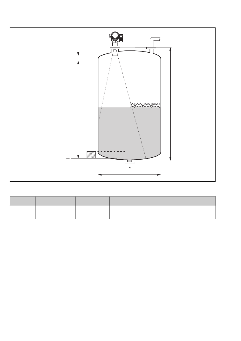
• The measuring range begins, where the beam hits the tank bottom. Particularly with dish
bottoms or conical outlets the level cannot be detected below this point.
• In stilling well applications, the electromagnetic waves do not propagate completely outside
the tube. It must be taken into account that the accuracy may be reduced in the area C. In
order to guarantee the required accuracy in these cases, it is recommended to position the
zero-point at a distance C above the end of the tube (see figure).
• In case of media with a low dielectric constant (εr = 1.5 to 4)
2)
the tank bottom can be
visible through the medium at low levels (low height C). Reduced accuracy has to be
expected in this range. If this is not acceptable, we recommend positioning the zero point at
a distance C (see figure) above the tank bottom in these applications.
• In principle it is possible to measure up to the tip of the antenna with FMR51, FMR53 and
FMR54. However, due to considerations regarding corrosion and build-up, the end of the
measuring range should not be chosen any closer than A (see figure) to the tip of the
antenna.
• When using FMR54 with planar antenna, especially for media with low dielectric constants,
the end of the measuring range should not be closer than A: 1 m (3.28 ft) to the flange.
• The smallest possible measuring range B depends on the antenna version (see figure).
• The tank height should be at least H (see table).
1)
,
1) Affected compounds are e.g. R134a, R227, Dymel 152a.
2) Dielectric constants of important media commonly used in various industries are summarized in the DC manual
(CP01076F) and in the Endress+Hauser "DC Values App" (available for Android and iOS).
Endress+Hauser 19
Installation Micropilot FMR50 HART
100%
0%
B
A
C
H
øD
Device A [mm (in)] B [m (ft)] C [mm (in)] H [m (ft)]
FMR50 150 (
5.91)
> 0.2 (0.7) 50 to 250 (1.97 to 9.84) > 0.3 (1.0)
6.3 Installation in vessel (free space)
6.3.1 Horn antenna encapsulated (FMR50)
Alignment
• Align the antenna vertically to the product surface.
• A marking at the threaded connection enables alignment of the antenna. This marking
must be aligned towards the tank wall as well as possible.
20 Endress+Hauser
A0018872
 Loading...