

Endress+Hauser Memograph M RSG40 Technical Information
Technical Information
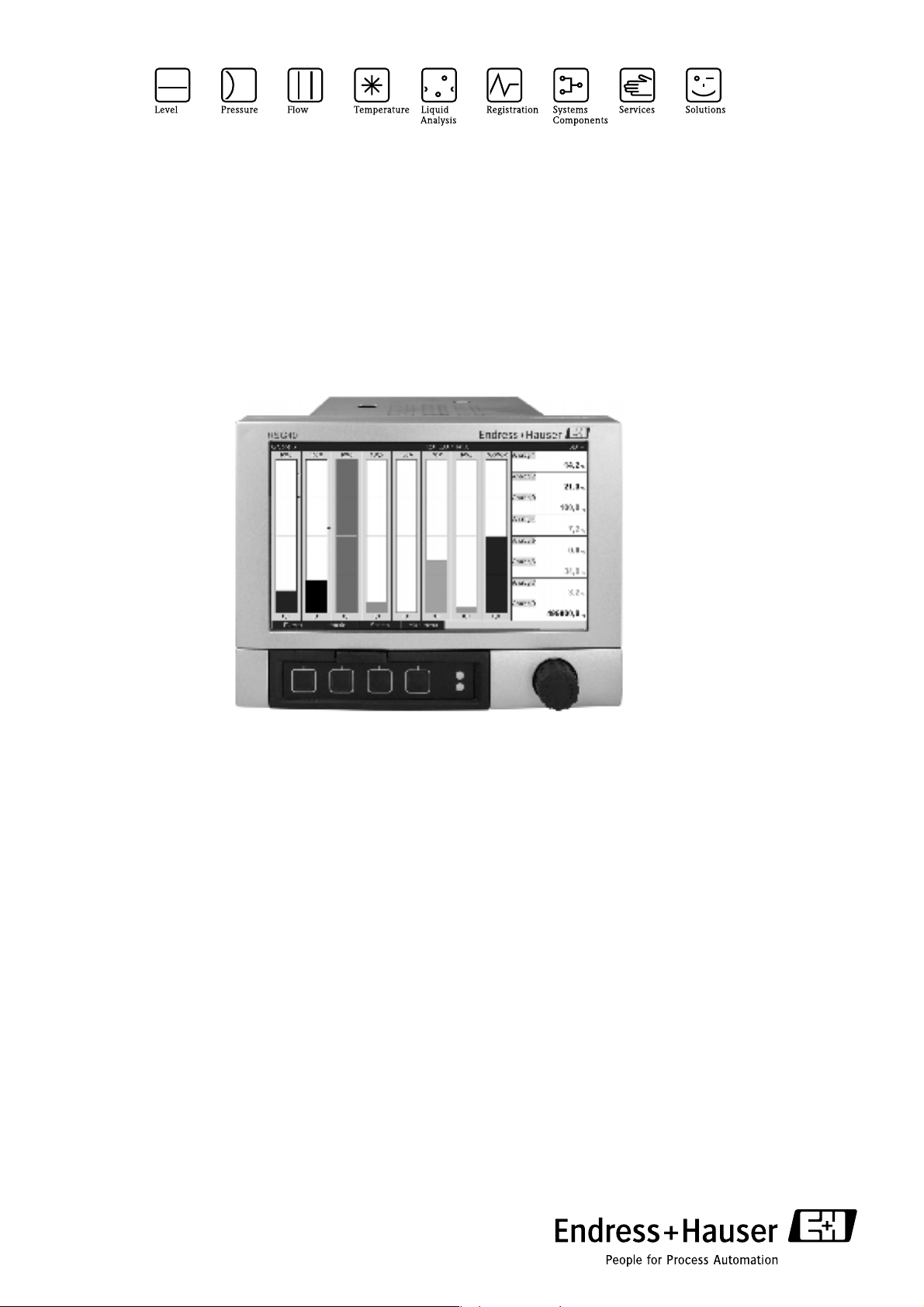
Memograph M
Graphic Data Manager RSG40
Record, visualize, analyze and communicate
Application
The graphic data manager Memograph M provides
information on all the relevant process variables.
Measured values are recorded correctly, limit values are
monitored and measuring points analyzed. The data are
stored in the 256 MB internal memory and also on an SD
card or USB stick. Memograph M boasts a modular
design, intuitive operation and a comprehensive security
concept. The ReadWin
standard package and is used for configuring, visualizing
and archiving the data captured.
The solution for all your tasks. For example, for:
• Process measuring technology
• Power stations and energy supply
• Food and pharmaceutical industry
• Environmental and climate measuring technology
• Quality assurance and production
• Plant and apparatus engineering and construction
• Testing bays and laboratory applications
®
2000 PC software is part of the
4
Your benefits
• Visual: 7" TFT display as onsite display for optimum
readability
• Fast: 100 msec scan rate for all channels, high-speed
memory cycle 100 msec for up to 8 channels
• Secure: Security package with person-specific access
authorization and electronic signature (FDA 21 CFR
11)
• Modular: Easy retrofitting to up to 20 universal inputs
and 14 digital inputs or 12 relays
• Flexible: Free choice of display mode. Completely
new: instrument and circular chart display
• Limitless: Integrated Web server, fieldbus (Profibus,
Modbus), common standard protocols and interfaces
such as USB, TCP/IP, OPC and Ethernet are
supported
• Informative: Event search, automatic signal analysis
• Practicable: Installation depth 158 mm, plastic front
IP65, NEMA4
• Clear: Alarm management with all active, confirmed
and historical alarms
TI133R/09/en
No. 71035347

Memograph M
Function and system design
Measuring principle Electronic acquisition, display, recording, analysis, remote transmission and archiving of analog and digital
input signals.
Measuring system Multichannel data recording system with multicolored TFT display (170 mm/7" screen size), galvanically
isolated universal inputs (U, I, TC, RTD, pulse, frequency), digital input, transmitter power supply, limit relay,
Block circuit diagram
!
communication interfaces (USB, Ethernet, RS232/485), internal SD memory, external SD card and USB stick.
100 ms scan rate for all channels. ReadWin
data evaluation.
Note!
The number of inputs, outputs and relays contained in the basic device can be individually extended using a
maximum of five plug-in cards. The Memograph M provides power directly to connected two-wire
transmitters. The device is configured and operated via 4 keys and the navigator (jog/shuttle dial) by means of
the interface and ReadWin
®
2000 PC software or an external keyboard. The online help makes onsite
operation easier. Measured values, events and alarms are coded in accordance with the serial protocol and then
transmitted.
Memory
®
2000 PC software for comprehensive device configuration and
Communication
PSTN-/GSM-Modem
Serial connection
RS232, RS485 (option)
ReadWin®2000
PC software
Ethernet (Option)
USB
Web-Server function
OPC-Server option()
Fieldbus up to 40
channels (option):
-Profibus DP Slave
-Modbus RTU
-Modbus TCP/IP
24 V, 200 mA
Transmitter power supply
output
115/230 V AC
24 V AC/DC
Slots for external
SD-card and USB-stick
*.csv
*.dat
256 MB
Internal
memory
TFT 7”
Display
•
100 limit values
(variable channel mapping)
0 to 20 analog inputs:
-TC
- RTD
-mA
- mV, V
- Frequency
- Pulse
Option:
- 8 mathematic channels
Mathematic functions over
formula editor freely editable
V
0/4..20mA
Relays:
- 1 change-over contact
- 5 to 11 normally
M
open contacts
Inputs
mA
6 to 14 digital inputs
-Event
-Time
-Counter
-Control function
2 analog outputs option
-Current output or
-Frequency output
():
Outputs
:
Power
This block circuit diagram provides a rough overview of the functions.
2 Endress+Hauser

Memograph M
Application packages/ software options
User-friendly function extension (even subsequently) through the online activation of all the optional
instrument functions. The following software options are available:
Software package
Functions Standard incl. security
package
Integration/totalizers ÃÃ
Min./max. value, average value recording ÃÃ
Signal analysis: day, week, month, year,
external (digital input)
Event messages ÃÃ
Operation time counter ÃÃ
Text entry/comments ÃÃ
Change language ÃÃ
Time synchronization ÃÃ
Screensaver ÃÃ
ÃÃ
Mathematics package
Web server/e-mail ÃÃ
Linearization ÃÃ
External keyboard ÃÃ
Access protection through release code ÃÃ
Mathematics functions via formula editor Ã
Logic operations Ã
User administration 21 CFR Part 11 ÃÃ
Endress+Hauser 3

Input
Analog multifunction inputs Number
Standard version without universal inputs.
Optional multifunction input cards (slot 1-5) each with 4 universal inputs (4/8/12/16/20).
Function
You can choose between the measured variables U, I, RTD, TC, pulse input or frequency input for each
universal input.
Measured variable, measuring range
To IEC 60873-1:
An additional display error of -/+ 1 digit is permitted for every measured value.
Measuring ranges which can be selected per channel:
Memograph M
Measured
variable
Current (I) 0 to 20 mA
0 to 5 mA
4 to 20 mA
Overrange: up to 22 mA
Voltage (U) > 1 V 0 to 10 V
Voltage (U) ≤ 1 V 0 to 1 V
Resistance
thermometer
(RTD)
Thermocouples
(TC)
0 to 5 V
± 10 V
± 30 V
± 1 V
± 150 mV
Pt100: -200 to 850 °C (-328 to 1562 °F) (IEC751, GOST)
Pt100: -200 to 649 °C (-328 to 1200.2 °F) (JIS1604)
Pt500: -200 to 850 °C (-328 to 1562 °F) (IEC751)
Pt500: -200 to 649 °C (-328 to 1200 °F) (JIS1604)
Pt1000: -200 to 600 °C (-328 to 1112 °F) (IEC751, JIS1604)
Cu100: -200 to 200 °C (-328 to 392 °F) (GOST)
Cu50: -200 to 200 °C (-328 to 392 °F) (GOST)
Pt50: -200 to 850 °C (-328 to 1562 °F) (GOST)
Type J (Fe-CuNi): -210 to 1200 °C (-346 to 2192 °F) (IEC581-1)
Type K (NiCr-Ni): -270 to 1372 °C (-454 to 2501.6 °F) (IEC581-1)
Type T (Cu-CuNi): -270 to 400 °C (-454 to 752 °F) (IEC581-1)
Type N (NiCrSi-NiSi): -270 to 1300 °C (-454 to 2372 °F) (IEC581-1)
Type L (Fe-CuNi): -200 to 900 °C (-328 to 1652 °F) (DIN43710)
Type L (Fe-CuNi): -200 to 659 °C (-328 to 1218.2 °F) (GOST)
Measuring range Maximum measured error
of measuring range (oMR)
± 0.10 % oMR Load: ≤ 50 Ohm
± 0.10 % oMR ≥ 1 MOhm
± 0.10 % oMR ≥ 2.5 MOhm
4-wire: ± 0.10 % oMR
4-wire: ± 0.10 % oMR
3-wire: ± (0.10 % oMR + 0.8 K)
3-wire: ± (0.10 % oMR + 0.8 K)
2-wire: ± (0.10 % oMR + 1.5 K)
4-wire: ± 0.20 % oMR
3-wire: ± (0.20 % oMR + 0.8 K)
2-wire: ± (0.20 % oMR + 1.5 K)
± 0.10 % oMR as of -100 °C (-148 °F)
± 0.10 % oMR as of -130 °C (-202 °F)
± 0.10 % oMR as of -200 °C (-328 °F)
± 0.10 % oMR as of -100 °C (-148 °F)
± 0.10 % oMR as of -100 °C (-148 °F)
± 0.10 % oMR as of -100 °C (-148 °F)
Input
resistance
≥ 1 MOhm
Type D (W3Re-W25Re): 0 to 2315 °C (32 to 4199 °F) (ASTME998)
Type C (W5Re-W26Re): 0 to 2315 °C (32 to 4199 °F) (ASTME998)
Type B (Pt30Rh-Pt6Rh): 0 to 1820 °C (32 to 3308 °F) (IEC581-1)
Type S (Pt10Rh-Pt): -50 to 1768 °C (-58 to 3214.4 °F) (IEC581-1)
Type R (Pt13Rh-Pt): -50 to 1768 °C (-58 to 3214.4 °F) (IEC581-1)
Pulse input (I) Min. pulse length 30 μs, max. 13 kHz
Frequency input (I) 0 to 10 kHz, overrange: to 12.5 kHz ± 0.01 % oMR Load: ≤ 50 Ohm
± 0.15 % oMR as of 500 °C (932 °F)
± 0.15 % oMR as of 500 °C (932 °F)
± 0.15 % oMR as of 600 °C (1112 °F)
± 0.15% oMR as of 100 °C (212 °F)
± 0.15% oMR as of 100 °C (212 °F)
≥ 1 MOhm
Maximum input load
Limit values for input voltage and input current as well as cable open circuit detection/line influence/
temperature compensation:
4 Endress+Hauser

Memograph M
Measured variable Limit values (steady-state,
without destroying input)
Current (I) Maximum permitted input voltage: 2.5 V
Pulse,
frequency (I)
Voltage (U) > 1 V Maximum permitted input voltage: 35 V
Voltage (U) ≤ 1 V Maximum permitted input voltage: 24 V
Resistance
thermometer (RTD)
Maximum permitted input current: 50 mA
Maximum permitted input voltage: 2.5 V
Maximum permitted input current: 50 mA
Minimum pulse length: 30 μs
Maximum 13 kHz
Measuring current: ≤ 1 mA Maximum barrier resistance (or line resistance):
Cable open circuit detection/line influence/temperature
compensation
4 to 20 mA range with disengageable cable open circuit detection as per NAMUR
NE43. The following error ranges apply if NE43 is activated:
≤ 3.8 mA: underrange (display shows: vvvvvv)
≥ 20.5 mA: overrange (display shows: ^^^^^^)
≤ 3.6 mA or ≥ 21.0 mA: cable open circuit (display: - - - -)
No cable open circuit monitoring
Max. 200 Ohm (4-wire)
Max. 40 Ohm (3-wire)
Maximum influence of barrier resistance (or line resistance) for Pt100, Pt500 and
Pt1000: 4-wire: ±0.0002%/Ohm, 3-wire: ±0.002%/Ohm
Maximum influence of barrier resistance (or line resistance) for Pt50, Cu100 and
Cu50: 4-wire: ±0.0006%/Ohm, 3-wire: ±0.006%/Ohm
Thermocouples (TC) Maximum permitted input voltage: 24 V Cable open circuit detection from 50 kOhm
Influence of line resistance in event of break detection: < 0.001%/Ohm
Error, internal temperature compensation: ≤ 2 K
Scan rate
All channels are scanned within 100 ms.
Converter resolution
24 bit
Totalization
The interim value, daily value, weekly value, monthly value, annual value and overall value can be determined
(13-digit, 64 bit).
Digital inputs Number
Standard version: 6 digital inputs
Optional digital card (slot 5): 8 additional digital inputs
Input level
To IEC 61131-2:
Logical "0" (corresponds to -3 to +5 V), activation with logical "1" (corresponds to +12 to +30 V)
Input frequency
Max. 25 Hz
Pulse length
Min. 20 ms
Input current
Max. 2 mA
Endress+Hauser 5

Memograph M
Input voltage
Max. 32 V (steady-state, without destroying input)
Selectable functions
Control input, ON/OFF message, pulse counter (13-digit, 64 bit), operating time, message+operating time,
quantity from time.
Functions of the control input: start recording, screensaver on, block setup, block keyboard/navigator, time
synchronization, change group, limit value monitoring on/off, individual LV on/off, start/stop evaluation.
Output
Auxiliary voltage output The auxiliary voltage is provided to activate the digital input (or the sensors) with floating contacts and is
galvanically isolated from the system and the inputs (testing voltage 500 V). The ground of the auxiliary voltage
and the ground of the digital input are electrically interconnected.
Output voltage:
Approx. 24 V DC, max. 28 V
Output current:
Maximum 200 mA, short-circuit proof, not stabilized
Relay outputs Standard version (power supply slot): 1 alarm relay with changeover contact, 5 relays with NO contact e.g. for
limit value alarms (can be configured as NC contact).
Optional digital card (slot 5): 6 additional relays with NO contact e.g. for limit value alarms (can be configured
as an NC contact).
!
Analog and pulse outputs Number:
Note!
It is not permitted to mix low voltage and safety extra low voltage (do not mix SELV circuits and low voltage).
Response time:
max. 400 ms
Maximum DC contact load:
50 V / 300 mA (steady-state, without destroying input)
Maximum AC contact load:
230 V / 3 A (steady-state, without destroying input)
Optional digital card (slot 5): 2 analog outputs which can be operated as current or pulse outputs.
Analog output (current output):
Output current: 0/4 to 20 mA with 10 % overrange
Max. output voltage: approx. 16 V
Accuracy: ≤ 0.1 % of output range
Temperature drift: ≤ 0.015 %/K
Resolution: 13 bit
Load: 0 to 500 Ohm
Error signal to NAMUR NE43: 3.6 mA or 21 mA can be configured
Digital output (pulse output):
Output voltage as per DIN 19240:
6 Endress+Hauser
 Loading...