

Page 1
BA 025D/06/e/03.97
No. 50078353
valid for software-version
V1.00.XX
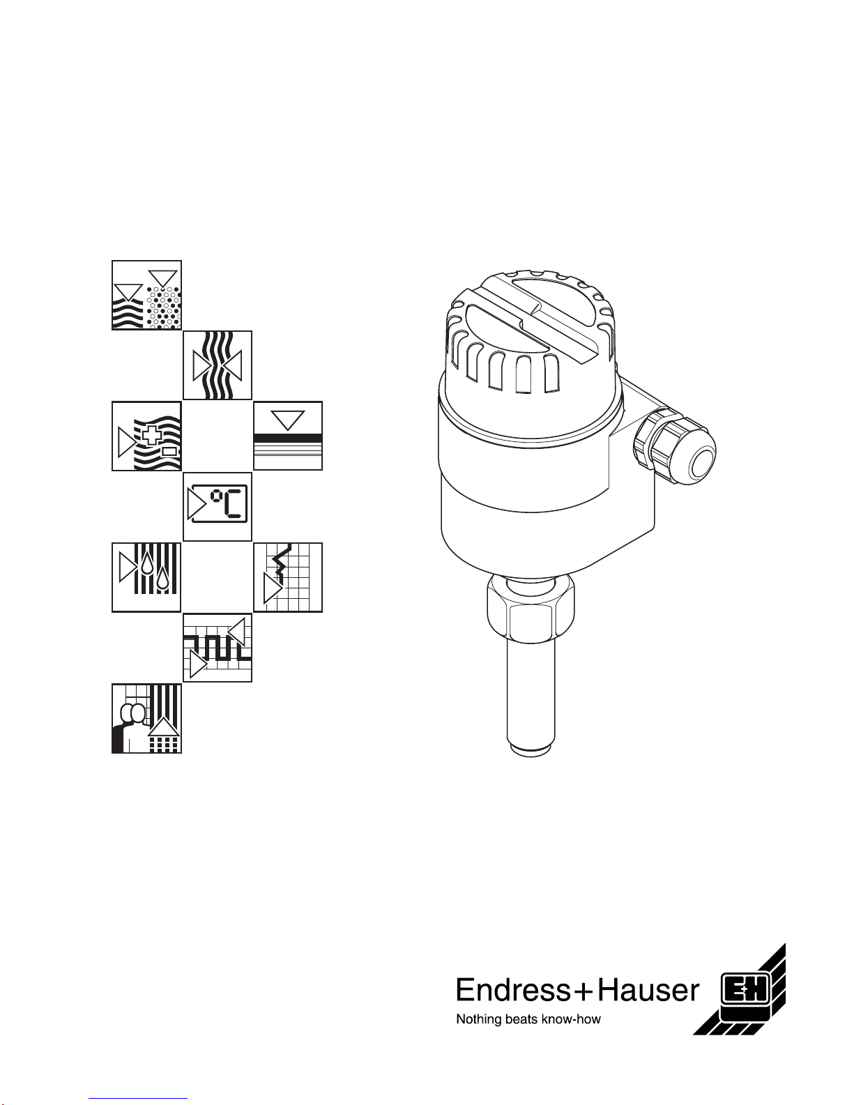
magphant
Electromagnetic
Flow Monitor
Operating Manual
AUTHORIZED DISTRIBUTOR:
InstrumentsAndControl.com
Houston, Texas USA
sales@InstrumentsAndControl.com
832-615-3588
Page 2

Safety Instructions
The following safety instructions must always be carefully observed!
Correct Usage
• The Magphant flow monitor may only be used for flow measurement of conductive liquids.
• The Magphant flow monitor is designed and checked according to the regulations in force
according to EN 61010 (VDE 0411, "Protection Measures for Electronic Measurement,
Control, Regulation and Laboratory Equipment”). A hazardous situation may occur if the
instrument is not used for the purpose it was designed
or is used incorrectly.
Please carefully note the information provided in this
Operating Manual indicated by the pictograms:
• The manufacturer assumes no liability for damage caused by incorrect use of the instrument.
Personnel for Installation, Start-up and Operation
• Mounting, electrical installation, start-up and maintenance of the instrument may only be
carried out by trained personnel authorised by the operator of the facility.
Personnel must read and understand this Operating Manual before carrying out its
instructions.
• The instrument may only be operated by personnel who are authorised and trained by the
operator of the facility. All instructions in this manual are to be observed.
• With special fluids, including those used for cleaning, E+H will be pleased to supply infor-
mation concerning the chemical resistance properties of wetted parts.
• Ensure that the measuring system is correctly wired up according to the wiring diagrams.
The flowmeter is to be grounded.
Repairs, Dangerous Chemicals
The following procedures must be carried out before a Magphant is sent to Endress+Hauser for
repair:
• A note must always be enclosed with the instrument, containing a description of the fault,
the application and the chemical and physical properties of the product being measured.
• Remove all residue which may be present. Pay special attention to the gasket grooves and
crevices where fluid may be present. This is especially important if the fluid is dangerous to
health, e.g. corrosive, carcinogenic, radioactive, etc.
• No instrument should be returned to us without all dangerous material being removed first
(e.g. in scratches or diffused through plastic).
Incomplete cleaning of the instrument may result in waste disposal or cause harm to personnel
(burns etc.). Any costs arising from this will be charged to the owner of the instrument.
Technical Improvements
The manufacturer reserves the right to modify technical data, to reflect development progress,
without prior notice. Your local E+H Sales Office will supply you with all current information and
any updates to this Operating Manual.
Safety Instructions Magphant
2 Endress+Hauser
Page 3

Table of contentsTable of contents
Safety Instructions . . . . . . . . . 2
1. System description . . . . . . . . 5
1.1 Areas of application . . . . . . . . . 5
1.2 Measuring principle . . . . . . . . . 5
1.3 Measuring system design . . . . . . . 6
2. Mounting and Installation . . . . . 7
2.1 Protection type IP 66 (DIN 40050) . . . . 7
2.2 Temperature ranges . . . . . . . . . 7
2.3 Mounting instructions . . . . . . . . . 8
2.4 Mounting in steel piping . . . . . . . . 9
2.5 Mounting in plastic piping . . . . . . . 10
3. Electrical Connection . . . . . . 13
3.1 General information . . . . . . . . . 13
3.2 Connecting the Magphant . . . . . . . 13
3.3 Commissioning . . . . . . . . . . . 14
4. Operation . . . . . . . . . . . 15
4.1 Operating and display surfaces . . . . . 15
5. Troubleshooting and Remedies . 17
5.1 Response of the measuring system to faults 17
5.2 Checking the electronics . . . . . . . 17
5.3 Replacing the electronics module . . . . 18
6. Technical Data . . . . . . . . . 19
6.1 Dimensions and weight . . . . . . . . 19
6.2 Technical Data . . . . . . . . . . . 20
Index . . . . . . . . . . . . . . 22
X
Magphant Table of contents
Endress+Hauser 3
Page 4

Magphant
4 Endress+Hauser
Page 5

1. System description
1.1 Areas of application
The Magphant flow monitor provides the plant system with the information needed on
flowrate in the piping. The magnetic-inductive measuring principle determines the
flow velocity of the conductive liquid at the tip of the sensor. Exceeding the preset
switchpoint (limit value) is indicated by a relay contact. An analogue 4...20 mA signal
proportional to the flow is also available for monitoring the flowrate at the same time.
The Magphant is ideal for process protection and monitoring.
1.2 Measuring principle
In accordance with Faradays law of magnetic induction, a voltage is induced in a conductor that is moved through a magnetic field. In the electromagnetic principle of
measurement the flowing fluid represents the moving conductor. The induced voltage
is proportional to the flow velocity and is fed to the measuring amplifier by a pair of
electrodes.
Microprocessor-controlled electronics, with a stable zero-point, convert the voltage
into an analogue 4...20-mA output signal.
U
e
= B x L x v = induced voltage
B = magnetic induction (magnetic field)
L = distance between electrodes
v = flow velocity at the tip of the sensor
ba025y08
Magnetic lines of force
B
Electrodes
Magnet ic co r e
Exciter coil
Sensor
L
U
e
v
Fig. 1:
Measuring principle of electromagnetic flow measurement
Magphant 1. System description
Endress+Hauser 5
Page 6

1.3 Measuring system design
A construction overview of the Magphant measuring system is shown in the diagram
below.
Operational safety
• Comprehensive self-monitoring of the measuring system assures high safety.
Any error messages that do occur (process errors, instrument system errors) are
immediately signalled via the current and relay outputs.
• The Magphant measuring unit fulfills the general safety requirements according to
EN 61010, as well as the general electromagnetic interference (EMI) immunity requirements EN 50081 Part 1 and 2 / EN 50082 Part 1 and 2.
• Protection type IP 66 is standard (DIN 40050).
Housing cover can be unscrewed.
After opening the cover, operating and displa y elements as well as the terminal block
are easily accessible.
Electronic s ho us ing
Ground terminal
PVC cable gland
PG 16
Sensor sleeve
Union nut
M30x2
with clamp ring
Weld stub
DN 25
Weld stub
≥DN 40
(mounting length indicated)
PVC cable gland
PG 16
ba025y04
Power supply 20...30 V DC
Signal cable
Electrodes
Union nut and
adapter for
Magphant
installation in
plast ic piping
Fig. 2:
Construction of the measuring
system
1. System description Magphant
6 Endress+Hauser
Page 7

2. Mounting and Installation
2.1 Protection type IP 66 (DIN 40050)
The Magphant fulfils all the requirements for IP 66.
Caution!
After successful installation in the field or after replacing an instrument, the following
points must always be observed in order to ensure protection to IP 66:
• Housing gaskets must be clean and undamaged and lie at the end of the cover
threads. The gaskets may need to be dried, cleaned or replaced.
• The screw cover must be firmly tightened.
• The cables used for connecting must have an outer diameter of 7...12 mm.
• The cable glands must be firmly tightened.
• The cable must loop down before entering the cable gland to ensure that no mois-
ture can enter it.
• An unused cable gland is to be replaced with a blind plug.
• The protective bush should not be removed from the cable gland.
2.2 Temperature ranges
Caution!
• The maximum approved ambient and fluid temperatures must be observed
(see Page 20).
• For outside installation of the instrument, take care that it is protected from direct
sunlight. This applies especially in countries with high ambient temperatures.
ba025y10
Fig. 3:
Mount ing re gu lat ion s for ca ble
glands
Magphant 2. Mounting and Installation
Endress+Hauser 7
Page 8

2.3 Mounting instructions
Orientation in the piping
The Magphant is best mounted in vertical piping.
If the piping runs horizontally, then the Magphant is to be mounted to the side.
This mounting procedure ensures that the electrodes are always immersed in flowing
fluid.
Caution!
Never weld the weld stub to the pipe with the Magphant in place.
Position of the electrode axis
The sensor is to be mounted so that the electrode axis is always 90° to the direction of
flow. The two PG 16 cable glands can be used as a visual check as these also lie on
the same axis.
45°
Preferred mounting orientati on Non-recommended mounting
orientation
Possible
air bubbles
Possible
build-up
of solids
ba025y05
Recommended inlet and outlet pipe sections: 5...10 x DN
Fig. 4:
Mounting orientation in horizontal piping
Required orientation
ba025e18
Fig. 5:
Orientation of the electrode axis
and PG 16 cable glands
2. Mounting and Installation Magphant
8 Endress+Hauser
Page 9

2.4 Mounting in steel piping
The Magphant is mounted in steel piping using the weld stub supplied.
Two different versions are available, depending on nominal diameter:
Weld stub for DN 25
For DN 25 piping, the weld stub has the appropriate radius to match the diameter.
• Opening in the piping: ∅ = 23 mm.
• Place the weld stub on the opening and weld it at right angles to the axis of the
piping.
Weld stub for ≥DN 40
For ≥DN 40 piping, the weld stub has a graduated scale to ensure that the stub can
be correctly positioned for mounting.
• Opening in the piping: ∅ = 30 mm.
• Insert the weld stub into the opening, with the marking (according to the nominal
diameter) flush against the outer wall of the piping and weld it at right angles to the
axis of the piping. For diameters >DN 300, the DN 300 marking is to be used.
ba025y07
Wrench size
27 mm
Welding seam
Fig. 6:
DN 25 weld stub
ba025y11
Welding seam
Wrench size
27 mm
Fig. 7:
≥
DN 40 weld stub
Magphant 2. Mounting and Installation
Endress+Hauser 9
Page 10

Mounting of the adapter piece for steel piping
1. Insert the Magphant into the weld stub and tighten the union nut by hand.
2. Hold the weld stub with a open-ended wrench size 27 mm.
3. Tighten the union nut a further approx.
1
⁄
2
turn with a open-ended wrench size
36 mm.
Caution!
When inserting the Magphant into a weld stub, care must be taken so that the sensor
tip is not damaged.
2.5 Mounting in plastic piping
The Magphant for mounting in plastic piping is delivered as part of a set, consisting
of the Magphant, an adapter piece made of 1.4435 (316L), and a plastic union nut.
Mounting of the adapter piece for plastic pipin g
1. Place the plastic union nut over the adapter piece.
2. Carefully insert the Magphant into the adapter piece and hand tighten the metal
union nut.
3. Hold the weld stub with a open-ended wrench size 25 mm.
Tighten the union nut a further approx.
1
⁄
2
turn with a open-ended wrench size
36 mm.
Caution!
When inserting the Magphant into a adapter piece, care must be taken so that the
sensor tip is not damaged.
Wrench size 36 mm
Wrench size 27 mm
Weld stub
Union nut
ba025y16
Fig. 8:
Mounting of the adapter piece for
steel pip in g
Wrench size 36 mm
Wrench size 25 mm
Adapter piece
Union nut
ba025y20
Plastic union nut
Fig. 9:
Mounting of the adapter piece for
plast ic piping
2. Mounting and Installation Magphant
10 Endress+Hauser
Page 11

Mounting in the standard T-fitting for diameters DN 15...50
The T-fitting, which can be obtained from the Georg Fischer company in PVC, PP and
PVDF, serves as Magphant holder for diameters DN 15...50.
After the unit has been assembled as described on page 10, insert it into the plastic
T-section and screw on the plastic union nut tightly by hand.
Caution!
• Observe the electrode axis orientation (see page 8).
• Use only the Magphant version for mounting in plastic piping (different insertion
depths!)
ba025y19
Metal union nut
Plastic union nut
Adapter piece
T-fitting
Abb. 10:
Mounting procedure for
diameters DN 15...50 in
plastic
DN H
15
236
20
25
30
40
50
Magphant 2. Mounting and Installation
Endress+Hauser 11
Page 12

Mounting in plastic piping for diameters ≥DN 65
A plastic weld stub is used for mounting in plastic piping for diameters ≥DN 65.
These plastic weld stubs can be obtained from the Georg Fischer company in PVC,
PP and PE materials.
The L dimension must be adjusted by the customer accordingly, depending on the
pipe outer diameter.
The L dimension can be calculated based on the following formula:
S = pipe wall thickness
E = insertion depth of the plastic weld nipple
(E can be obtained from the table below)
Caution!
• Observe the electrode axis orientation (see page 8).
• Use only the Magphant version for mounting in plastic piping (different insertion
depths!)
Detail A
Detail A
two O-rings
ba025y23
• Hole in pipe = ∅ 40 mm
• Weld the weld stub
perpendicular to the pipe
Abb. 1 1:
Mounting in plastic piping for
diamet ers
≥
DN 65
ba025y21
Pipe outer
diameter
E
65 6.9
75 8.3
110 11.4
125 14.4
140 17.7
160 17.7
200 12.0
225 10.0
250 10.0
280 10.0
315 10.0
355 10.0
400 10.0
150 5.0
500 5.0
630 5.0
L = 40 - S - E
2. Mounting and Installation Magphant
12 Endress+Hauser
Page 13

3. Electrical Connection
3.1 General information
Note both the polarity and operating voltage.
Warning!
Do not install, wire up or dismantle the instrument when the power supply is switched
on.
3.2 Connecting the Magphant
Wiring and cable specifications
Wire cross-section : max. 1.5 mm
2
Cable diameter : 7...12 mm
Cable gland : PG 16
Shielded cable should always be used.
Fuse 160 mA slow -blow
Current output 4...20 mA
Load R
L
= 750 Ω max.
Relay output
75 V DC / 0.5 A
60 V AC / 0.4 A
Power supply 20...30 V DC
Terminal block
ba025y02
Signal cable
Power supply cabl e
Ground terminals
for cable shields
Fig. 12:
Electric al co nn ec tion
Magphant 3. Electrical Connection
Endress+Hauser 13
Page 14

Potential equalization
The Magphant should be connected to ground via the ground terminal at the housing
to ensure complete electromagnetic compatibility.
Note!
Take care that the ground cable is kept as short as possible.
3.3 Commissioning
Before switching on the measuring system, the following checks should be carried
out:
• Does the directional arrow on the Magphant agree with the actual flow direction,
i.e. do the two PG 16 cable glands lie at 90° to the direction of flow?
• Check the electrical connections and terminal assignments as shown on Page 13.
• Check that the local power supply agrees with the information stated on the name-
plate.
The following procedure should now be carried out:
1. Set miniature switch 1 (test mode) to the "normal" position (see Page 17).
2. Set the miniature switches 2 to 4 for
– time constant / relay latch time
– relay function
– min. / max. fail-safe
as appropriate.
3. After switching on the power supply, the outputs are deactivated for 5s (relay deenergised and current output remains at 0 mA). Both LEDs flash during this procedure.
4. Set the full-scale value. This can be done in two ways:
Full-scale value with actual flow (local calibration)
– Take into account general flowrates anticipated.
– Turn the full-scale potentiometer until the green LED lights up (see Page 16).
Setting the full-scale value without actual flow
– Set the full-scale potentiometer at the mean flow rate anticipated.
5. Use the limit switch to set the relay switchpoint in % of the preset full-scale as
described in Point 4.
Note!
A detailed description of the display and operating elements is given on Page 15/16.
4 mm2 Cu wire
ba025y03
Fig. 13:
Magpha nt potential equalization
3. Electrical Connection Magphant
14 Endress+Hauser
Page 15

4. Operation
4.1 Operating and display surfaces
Note!
Customer settings can be noted on the operating and display surface.
Setting limit value as
percentage of the set
full-scale value
Potentiometer for
setting the full-scale
Green LED
for full-scale setting
Red LED
for limit value or error
indication
Test mode
Current output
Time constant and
relay latch time
Relay function Min. /max fail-safe
ba025y09
Fig. 14:
Operating and display el ements
with factory settings
Functions of the operating and display elements
Operating and display element
(factory setting)
Description of function
Time constant / Relay latch time
The times t = 3 s and t =10 s correspond to the current
output time constant and also to the relay latch time.
t = 3 s: The relay switches immediately and then remains
in this state for 3 seconds.
t = 10 s: The relay first switches when the measured value
is below or above the limit value for a continuous
10 seconds.
Relay functions
The relay is energised if all functions are operating
correctly. The relay is de-energised immediately when an
error or alarm occurs.
limit
The relay de-energises or the red LED lights up if the
signal moves outside the upper or lower limit value
(depending on the min./max. fail-safe setting).
(limit) + error
The same function as for "limit", but in addition:
The relay de-energises if the flow rate is larger than the
measurable value of the Magphant or if an instrument error
occurs. The red LED flashes. "Error" has higher priority
than "limit".
Magphant 4. Operation
Endress+Hauser 15
Page 16

Note!
The function of the miniature switch for the test mode is described on Page 17.
Functions of the operating and display elements
Operating and display element
(factory setting)
Description of function
Min./max. fail-safe setting
Maximum fail-safe: The relay de-energises if the signal
rises above the limit value.
The red LED lights up.
Minimum fail-safe: The relay de-energises if the signal
falls below the limit value.
The red LED lights up.
Full-scale settin g
The full-scale setting is infinitely variable using this
potentiometer between 1...5 m/s.
Turning the potentiometer
The transition from a green LED which is off to a lighted
LED shows agreement between the momentary flow
velocity and the set full scale value, at which the current
output will be set to 20 mA.
Green LED
Lit: When the actual flow rate is smaller
than the set full-scale value, i.e.
I = <20 mA.
Setting the limit value
A limit value as a % of the full-scale value is set using this
rotary switch. It is adjustable in 10 % steps from
10 % to 100 %.
Red LED
Lit: Limit value reached
Flashing: Error indication (see Page 17)
(1.5 Hz)
Potentiometer
Green LED
Limit value
switch
Red LED
4. Operation Magphant
16 Endress+Hauser
Page 17

5. Troubleshooting and Remedies
5.1 Response of the measuring system to faults
• Error messages which occur during measurement are always indicated via the
current and, depending on the preset relay function, also via the relay output.
• In addition, a system or process error is always indicated when the red LED flashes.
5.2 Checking the electronics
The Magphant can be set to a test mode using miniature switch No. 1:
1. Set test mode switch to "test".
2. Turn the full-scale potentiometer anticlockwise until it comes to the mechanical
stop, the current output must now be exactly 20 mA.
3. If this is not the case, then the electronics module must be replaced.
T ype of error Relay
(when set in
"limit+error"
position)
Red LED Current output
System errors: Amplifier error
EEPROM error
de-energised flashing 2 mA
Process errors: Overflow de-energised flashing 2 mA
Tes t mode
Magphant 5. Troubleshooting and Remedies
Endress+Hauser 17
Page 18

5.3 Replacing the electronics module
Warning!
Switch off the power supply before unscrewing the cover to the electronics
compartment.
Procedure:
1. Switch off the power supply.
2. Unscrew the housing cover.
3. Remove all wires from the terminal block.
4. Undo the Phillips screws of the circuit board plate.
5. Undo the mounting screw of the ground wire (cable socket).
6. Carefully remove the board support plate from the housing.
7. Remove the excitation current cable plug from the power supply board.
8. Remove the electrode signal cable plug from the amplifier board.
9. Remove the old electronics module.
10. Replace with a new electronics module and reassemble in reverse order.
Remove excitation
current cable plug
Unplug the electrode
signal cable plug
Carefully remove the
electronics module
ba025y15
Fig. 15:
Replacing the electronics module
5. Troubleshooting and Remedies Magphant
18 Endress+Hauser
Page 19

6. Technical Data
6.1 Dimensions and weight
Union nut
M 30 x 2
Cable gland
Weight: 1.2 kg
Note!
Dimensions of the weld stub see Page 9
ba025y01
Nominal
diameter
H
for mounting in
steel piping
H
for mounting in
plastic piping
25
40
50
80
100
150
200
250
≥300
237.0
234.0
234.0
230.0
227.0
220.5
214.5
207.5
201.5
see page
11 und 12
Fig. 16:
Dimens ion s and weight
Magphant 6. Technical Data
Endress+Hauser 19
Page 20

6.2 Technical Data
Power supply 24 V DC (20...30 V DC)
Power consumption <2.5 W
Outputs • Current output 4...20 mA, active
The measuring system can measure flow in both
directions, i.e. bidirectionally.
The current output is always positive. The relay
responds to both flow directions.
• Relay output
Potential-free change-over contact
60 V AC / 0.4 A or 75 V DC / 0.5 A
Ambient temperature -20...60 °C
Process temperature -20...120 °C (weld stub 1.4435 with clamp ring)
-20...100 °C (weld stub St. 37 with clamp ring and
NBR gasket)
Pressure 16 bar at 25 °C
10 bar at 120 °C
Full-scale value 1...5 m/s (infinitely variable)
Accuracy ±2% o.r. at measuring electrode with local calibration
at flow velocities >1 m/s
Reproducibility ±2% o.r.
Conductivity ≥20 µS/cm
Interference immunity acc. to CE EN 50081-1-2 and EN 50082-1-2
Protection type IP 66 / NEMA 4X / Type 4X
Current [mA]
20.5 mA
20 mA
Scaled
full-scale
value
Scaled
full-scale
value
reverse
forward
Flow
rate. [m/s]
ba025y14
Pressure [bar]
Temp.
[°C]
ba025y24
6. Technical Data Magphant
20 Endress+Hauser
Page 21

Materials
Sensor Sensor tip:
PVDF, Viton O-ring
Electrodes:
1.4435/316L
Sensor sleeve:
• 1.4435/316L with 1.4571/316Ti clamp ring
for 1.4435/316L weld stub
• 1.4435/316L with clamp ring and NBR gasket
for St.37/A570 weld stub
Housing Aluminium, epoxy powder coated
Weld stub 1.4435/316L
(for steel piping) St.37/A570
Adapter piece 1.4435/316L (with 2 Viton O-rings)
(for plastic piping)
Plastic union nut PVC
(for plastic piping)
Approvals CENELEC:
VDE 0165 manufacturers certificate for Zone 2
SEV: Ex nV/W IIC T4...T6, Zone 2
FM: NI Cl I Div 2 Gp ABCD; DIP/II, III/1/EFG. NEMA 4X
CSA: Class I Div 2, Groups A,B,C and D;
Class II E,F and G, Class III; Type 4X
Thermal data and temperature classes for Ex Zone 2
IEC 758 T
fluid
T
ambient
(see Page 20)
T1
T2
T3
T4
T5
T6
100° C/120°C
100° C/120°C
100° C/120°C
100° C/120°C
95° C/ 95°C
80° C/ 80°C
60° C
60° C
60° C
60° C
60° C
40° C
Magphant 6. Technical Data
Endress+Hauser 21
Page 22

Index
X
Index
A
Accuracy . . . . . . . . . . . . . . . . . 20
Ambient temperature . . . . . . . . . . . . 20
Applications . . . . . . . . . . . . . . . 5
Approvals . . . . . . . . . . . . . . . . 21
C
Cable specifications . . . . . . . . . . . . 13
Checking the electronics . . . . . . . . . . 17
Commissioning . . . . . . . . . . . . . . 14
Conductivity . . . . . . . . . . . . . . . 20
Current output . . . . . . . . . . . . . . . 20
D
Dangerous chemicals . . . . . . . . . . . . 2
Dimensions . . . . . . . . . . . . . . . . 19
E
Electrical connection . . . . . . . . . . 13, 14
Electrode axis . . . . . . . . . . . . . . . 8
Electronics module . . . . . . . . . . . . . 18
F
Fail-safe setting . . . . . . . . . . . . . . 16
Faults . . . . . . . . . . . . . . . . . . 17
Full-scale setting . . . . . . . . . . . . . . 16
Full-scale value . . . . . . . . . . . . . . 20
I
Inlet sections . . . . . . . . . . . . . . . 8
Installation . . . . . . . . . . 7, 8, 9, 10, 11, 12
Interference immunity . . . . . . . . . . . . 20
L
LED green/red . . . . . . . . . . . . . . . 16
M
Materials . . . . . . . . . . . . . . . . . 21
Measuring principle . . . . . . . . . . . . 5
Measuring system . . . . . . . . . . . . 6, 17
Measuring system design . . . . . . . . . . 6
Mounting . . . . . . . . . . . 7, 8, 9, 10, 11, 12
Mounting instructions . . . . . . . . . . . . 8
O
Operating and display elements . . . . . . . . 15
Operation . . . . . . . . . . . . . . 15, 16
Operational safety . . . . . . . . . . . . . 6
Orientation . . . . . . . . . . . . . . . . 8
Outlet sections . . . . . . . . . . . . . . 8
P
Position of the electrode axis . . . . . . . . . . 8
Potential equalization . . . . . . . . . . . . 14
Power consumption . . . . . . . . . . . . 20
Power supply . . . . . . . . . . . . . . 6, 20
Pressure . . . . . . . . . . . . . . . . . 20
Process errors . . . . . . . . . . . . . . 17
Process temperature . . . . . . . . . . . . 20
Protection measures . . . . . . . . . . . . . 2
Protection type . . . . . . . . . . . . 6, 7, 20
R
Regulations . . . . . . . . . . . . . . . . 2
Relay functions . . . . . . . . . . . . . . 15
Relay latch time . . . . . . . . . . . . . . 15
Relay output . . . . . . . . . . . . . . . 20
Replacing the electronics module . . . . . . . 18
Reproducibility . . . . . . . . . . . . . . 20
S
Safety instructions . . . . . . . . . . . . . . 2
Setting the limit value . . . . . . . . . . . . 16
System description . . . . . . . . . . . . 5, 6
System error . . . . . . . . . . . . . . . 17
T
Technical data . . . . . . . . . . . 19, 20, 21
Temperature ranges . . . . . . . . . . . . . 7
Test mode . . . . . . . . . . . . . . . . 17
Time constant . . . . . . . . . . . . . . 15
Troubleshooting . . . . . . . . . . . . . . 17
W
Weight . . . . . . . . . . . . . . . . . 19
Weld stub . . . . . . . . . . . . . . . . . 9
Wiring . . . . . . . . . . . . . . . . . 13
Index Magphant
22 Endress+Hauser
Page 23

Page 24

Europe
Aust ria
Endress+Hauser Ges.m.b.H.
Wien
Tel. (01) 88056-0, Fax (01) 88056-35
Belarus
Belorgsintez
Minsk
Tel. (0172) 508473, Fax (0172) 508583
Belgium / Luxembourg
Endress+Hauser N.V.
Brussels
Tel. (02) 2480600, Fax (02) 2480553
Bulgaria
INTERTECH-AUTOMATION
Sofia
Tel. (02) 664869, Fax (02) 9631389
Croatia
Endress+Hauser GmbH+Co.
Zagreb
Tel. (01) 6637785, Fax (01) 6637823
Cyprus
I+G Electrical Services Co. Ltd.
Nicosia
Tel. (02) 484788, Fax (02) 484690
Czech Republic
Endress+Hauser GmbH+Co.
Praha
Tel. (026) 6784200, Fax (026) 6784179
Denmark
Endress+Hauser A/S
Søborg
Tel. (70) 131132, Fax (70) 132133
Estonia
ELVI-Aqua
Tartu
Tel. (7) 441638, Fax (7) 441582
Finland
Endress+Hauser Oy
Helsinki
Tel. (0204) 83160, Fax (0204) 83161
France
Endress+Hauser S.A.
Huningue
Tel. (389) 696768, Fax (389) 694802
Germany
Endress+Hauser Messtechnik GmbH+Co.
Weil am Rhein
Tel. (07621) 975-01, Fax (07621) 975-555
Great Britain
Endress+Hauser Ltd.
Manchester
Tel. (0161) 2865000, Fax (0161) 9981841
Greece
I & G Building Services Automation S.A.
Athens
Tel. (01) 9241500, Fax (01) 9221714
Hungary
Mile Ipari-Elektro
Budapest
Tel. (01) 4319800, Fax (01) 4319817
Iceland
BIL ehf
Reykjavik
Tel. (05) 619616, Fax (05) 619617
Ireland
Flomeaco Company Ltd.
Kildare
Tel. (045) 868615, Fax (045) 868182
Italy
Endress+Hauser S.p.A.
Cernusco s/N Milano
Tel. (02) 921921, Fax (02) 92107153
Latvia
Rino TK
Riga
Tel. (07) 315087, Fax (07) 315084
Lithuania
UAB "Agava"
Kaunas
Tel. (07) 202410, Fax (07) 207414
Netherland
Endress+Hauser B.V.
Naarden
Tel. (035) 6958611, Fax (035) 6958825
Norway
Endress+Hauser A/S
Tranby
Tel. (032) 859850, Fax (032) 859851
Poland
Endress+Hauser Polska Sp. z o.o.
Warszawy
Tel. (022) 7201090, Fax (022) 7201085
Portu gal
Tecnisis, Lda
Cacém
Tel. (21) 4267290, Fax (21) 4267299
Romania
Romconseng S.R.L.
Bucharest
Tel. (01) 4101634, Fax (01) 4112501
Russia
Endress+Hauser Moscow Office
Moscow
Tel. (095) 1587564, Fax (095) 1589871
Slovakia
Transcom Technik s.r.o.
Bratislava
Tel. (7) 44888684, Fax (7) 44887112
Slovenia
Endress+Hauser D.O.O.
Ljubljana
Tel. (061) 5192217, Fax (061) 5192298
Spain
Endress+Hauser S.A.
Sant Just Desvern
Tel. (93) 4803366, Fax (93) 4733839
Sweden
Endress+Hauser AB
Sollentuna
Tel. (08) 55511600, Fax (08) 55511655
Switzerland
Endress+Hauser Metso AG
Reinach/BL 1
Tel. (061) 7157575, Fax (061) 7111650
Tur ke y
Intek Endüstriyel Ölcü ve Kontrol Sistemleri
Istanbul
Tel. (0212) 2751355, Fax (0212) 2662775
Ukraine
Photonika GmbH
Kiev
Tel. (44) 26881, Fax (44) 26908
Yugoslavia Rep.
Meris d.o.o.
Beograd
Tel. (11) 4441966, Fax (11) 4441966
Africa
Egypt
Anasia
Heliopolis/Cairo
Tel. (02) 4179007, Fax (02) 4179008
Morocco
Oussama S.A.
Casablanca
Tel. (02) 241338, Fax (02) 402657
South Africa
Endress+Hauser Pty. Ltd.
Sandton
Tel. (011) 4441386, Fax (011) 4441977
Tun is ia
Controle, Maintenance et Regulation
Tunis
Tel. (01) 793077, Fax (01) 788595
America
Argentina
Endress+Hauser Argentina S.A.
Buenos Aires
Tel. (01) 145227970, Fax (01) 145227909
Bolivia
Tritec S.R.L.
Cochabamba
Tel. (042) 56993, Fax (042) 50981
Brazil
Samson Endress+Hauser Ltda.
Sao Paulo
Tel. (011) 50313455, Fax (011) 50313067
Canada
Endress+Hauser Ltd.
Burlington, Ontario
Tel. (905) 6819292, Fax (905) 6819444
Chile
Endress+Hauser Chile Ltd.
Santiago
Tel. (02) 3213009, Fax (02) 3213025
Colombia
Colsein Ltda.
Bogota D.C.
Tel. (01) 2367659, Fax (01) 6104186
Costa Rica
EURO-TEC S.A.
San Jose
Tel. (02) 961542, Fax (02) 961542
Ecuador
Insetec Cia. Ltda.
Quito
Tel. (02) 269148, Fax (02) 461833
Guatemala
ACISA Automatizacion Y Control
Industrial S.A.
Ciudad de Guatemala, C.A.
Tel. (03) 345985, Fax (03) 327431
Mexico
Endress+Hauser S.A. de C.V.
Mexico City
Tel. (5) 5682405, Fax (5) 5687459
Paragua y
Incoel S.R.L.
Asuncion
Tel. (021) 213989, Fax (021) 226583
Uruguay
Circular S.A.
Montevideo
Tel. (02) 925785, Fax (02) 929151
USA
Endress+Hauser Inc.
Greenwood, Indiana
Tel. (317) 535-7138, Fax (317) 535-8498
Venezuela
Controval C.A.
Caracas
Tel. (02) 9440966, Fax (02) 9444554
Asia
China
Endress+Hauser Shanghai
Instrumentation Co. Ltd.
Shanghai
Tel. (021) 54902300, Fax (021) 54902303
Endress+Hauser Beijing Office
Beijing
Tel. (010) 68344058, Fax (010) 68344068
Hong Kong
Endress+Hauser HK Ltd.
Hong Kong
Tel. 25283120, Fax 28654171
India
Endress+Hauser (India) Pvt Ltd.
Mumbai
Tel. (022) 8521458, Fax (022) 8521927
Indonesia
PT Grama Bazita
Jakarta
Tel. (21) 7975083, Fax (21) 7975089
Japan
Sakura Endress Co. Ltd.
Tokyo
Tel. (0422) 540613, Fax (0422) 550275
Malaysia
Endress+Hauser (M) Sdn. Bhd.
Petaling Jaya, Selangor Darul Ehsan
Tel. (03) 7334848, Fax (03) 7338800
Pakistan
Speedy Automation
Karachi
Tel. (021) 7722953, Fax (021) 7736884
Papua-Neuguinea
SBS Electrical Pty Limited
Port Moresby
Tel. 3251188, Fax 3259556
Philippines
Endress+Hauser Philippines Inc.
Metro Manila
Tel. (2) 3723601-05, Fax (2) 4121944
Singapore
Endress+Hauser (S.E.A.) Pte., Ltd.
Singapore
Tel. 5668222, Fax 5666848
South Korea
Endress+Hauser (Korea) Co., Ltd.
Seoul
Tel. (02) 6587200, Fax (02) 6592838
Taiwan
Kingjarl Corporation
Taipei R.O.C.
Tel. (02) 27183938, Fax (02) 27134190
Thailand
Endress+Hauser Ltd.
Bangkok
Tel. (2) 9967811-20, Fax (2) 9967810
Vietnam
Tan Viet Bao Co. Ltd.
Ho Chi Minh City
Tel. (08) 8335225, Fax (08) 8335227
Iran
PATSA Co.
Tehran
Tel. (021) 8754748, Fax (021) 8747761
Israel
Instrumetrics Industrial Control Ltd.
Netanya
Tel. (09) 8357090, Fax (09) 8350619
Jordan
A.P. Parpas Engineering S.A.
Amman
Tel. (06) 4643246, Fax (06) 4645707
Kingdom of Saudi Arabia
Anasia Ind. Agencies
Jeddah
Tel. (02) 6710014, Fax (02) 6725929
Lebanon
Network Engineering
Jbeil
Tel. (3) 944080, Fax (9) 548038
Sultanate of Oman
Mustafa Sultan Science & Industry Co. LLC.
Ruwi
Tel. 602009, Fax 607066
United Arab Emirates
Descon Trading EST.
Dubai
Tel. (04) 2653651, Fax (04) 2653264
Yem en
Yemen Company for Ghee and Soap Industry
Taiz
Tel. (04) 230664, Fax (04) 212338
Australia + New Zealand
Australia
ALSTOM Australia Limited
Milperra
Tel. (02) 97747444, Fax (02) 97744667
New Zealand
EMC Industrial Group Limited
Auckland
Tel. (09) 4155110, Fax (09) 4155115
All other countries
Endress+Hauser GmbH+Co.
Instruments International
D-Weil am Rhein
Germany
Tel. (07621) 975-02, Fax (07621) 975345
Members of the Endress+Hauser group
http://www.endress.com
09.01
 Loading...