

Page 1

BA276F/00/en/11.06
No. 52021033
Valid as of software version
V 01.04.00 (amplifier)
V 01.04.00 (communication)
Operating Instructions
Levelflex M FMP41C
Guided Level-Radar
HART/4...20 mA
6
Page 2

Brief overview Levelflex M FMP41C with HART/4...20 mA
2 Endress + Hauser
Brief overview
For quick and simple commissioning:
Safety Instructions → ä 6
Explanation of the warning symbols
You can find special instructions at the appropriate position in the chapter in
question. The positions are indicated with the icons Warning #, Caution " and
Note !.
Æ
Installation → ä 12
The steps for installing the device and installation conditions (e.g. dimensions)
can be found here.
Æ
Wiring → ä 22
The device is virtually completely wired on delivery.
Æ
Display and Operating Elements → ä 28
An overview of the position of the display and operating elements can be found
here.
Æ
Commissioning via Display VU331 → ä 41
In the "Commissioning" section, you learn how to switch on the device and
check the functioning.
Æ
Commissioning via Operating Software ToF Tool → ä 54
In the "Commissioning" section, you learn how to switch on the device and
check the functioning.
Additional information on the operation of the ToF Tool can be found in the
operating instructions BA224F/00.
Æ
Fault Tracking / Trouble Shooting → ä 65
If faults occur during operation, use the checklist to localise the cause.
Here you can find measures you can take yourself to take remedial action
against the fault.
Æ
Index → ä 89
You can find important terms and keywords on the individual sections here.
Use the keyword index to find quickly and efficiently the information you need.
Page 3

Levelflex M FMP41C with HART/4...20 mA Brief overview
Endress + Hauser 3
Brief operating instructions
L00-FMP40xxx-19-0 0-00-en-012
!
Note!
This operating manual explains the installation and initial start-up for the level transmitter
measuring device. All functions that are required for a typical measuring task are taken into account
here.
In addition, the Levelflex M provides many other functions that are not included in this operating
manual, such as optimising the measuring point and converting the measured values.
An overview of all device functions can be found on → ä 84.
An extensive description of all device functions can be found in BA245F – "Description of the
instrument functions" on the enclosed CD-ROM.
Operating Instructions can also be found on our homepage: www.endress.com
E
+
-
+
E
+
-
E
E
-
… …
… …
KA 189F/00/a2/11.05
52012501
52012501
100%
0%
F
E
UB
LN
D
L
Levelflex M - Brief operating instructions
input E
(see sketch)
input F
(see sketch) displayed
D and L are
confirm
or specify
range
suggestion
000
measured value
Group
selection
00
basic setup
01
safety settings
09
display
04
linearisation
05
extended calibr.
0C
system
parameters
092
language
0A
diagnostics
0A0
present
error
002
tank
properties
004
process
cond.
005
empty
calibr.
006
full
calibr.
008
dist./
meas value
051
check
distance
003
medium
property
052
range of
mapping
053
start
mapping
008
dist./
meas value
- envel. curve
- substracted signal
- mapping
- single curve
- cyclic
= 100: unlocked
¹ 100: locked
09A
plot settings
09B
recording
curve
0A1
previous
error
0A4
unlock
parameter
(333 = reset customer parameters)
0A3
reset
min. level
threaded
connection
1½
(G 1
:
reference point of
measurement
¾or BSP
¾orG ½)
¾or1½NPT
03
length
adjustment
030
end of
probe
031
probe
length
032
probe
033
probe
length
034
determine
length
- unknown
- 1.4 … 1.6
- 1.6 … 1.9
- 1.9 … 2.5
-4…7
-2.5…4
->7
0E
envelope curve
Contrast: +or +
- standard
- aluminium tank
- plastic tank
- bypass/pipe
- coax-probe
- concrete
wall
- standard
- fast
change
- test: no filter
- slow
change
- free
- tie down
isolated
- tie down
gnd.
If shortened
please enter probe lengthhere.
reference
point of
measurement
F = measuring span
E = empty distance (= zero)
UB = upper blocking distance
LN = probe length
L = level
D = distance
Page 4

Brief overview Levelflex M FMP41C with HART/4...20 mA
4 Endress + Hauser
Page 5

Levelflex M FMP41C with HART/4...20 mA Table of contents
Endress + Hauser 5
Table of contents
1 Safety instructions . . . . . . . . . . . . . . . . 6
1.1 Designated use . . . . . . . . . . . . . . . . . . . . . . . . . . . . 6
1.2 Installation, commissioning and operation . . . . . . . . 6
1.3 Operational safety . . . . . . . . . . . . . . . . . . . . . . . . . . 6
1.4 Notes on safety conventions and icons . . . . . . . . . . . 7
2 Identification . . . . . . . . . . . . . . . . . . . . 8
2.1 Device designation . . . . . . . . . . . . . . . . . . . . . . . . . 8
2.2 Scope of delivery . . . . . . . . . . . . . . . . . . . . . . . . . . 11
2.3 Certificates and approvals . . . . . . . . . . . . . . . . . . . 11
2.4 Registered trademarks . . . . . . . . . . . . . . . . . . . . . . 11
3 Installation . . . . . . . . . . . . . . . . . . . . . 12
3.1 Incoming acceptance, transport, storage . . . . . . . . . 12
3.2 Installation conditions . . . . . . . . . . . . . . . . . . . . . . 13
3.3 Installation . . . . . . . . . . . . . . . . . . . . . . . . . . . . . . 15
3.4 Turn housing . . . . . . . . . . . . . . . . . . . . . . . . . . . . . 21
3.5 Post-installation check . . . . . . . . . . . . . . . . . . . . . . 21
4 Wiring . . . . . . . . . . . . . . . . . . . . . . . . 22
4.1 Quick wiring guide . . . . . . . . . . . . . . . . . . . . . . . . 22
4.2 Connecting the measuring unit . . . . . . . . . . . . . . . 24
4.3 Recommended connection . . . . . . . . . . . . . . . . . . 27
4.4 Degree of protection . . . . . . . . . . . . . . . . . . . . . . . 27
4.5 Post-connection check . . . . . . . . . . . . . . . . . . . . . . 27
5 Operation . . . . . . . . . . . . . . . . . . . . . . 28
5.1 Quick operation guide . . . . . . . . . . . . . . . . . . . . . . 28
5.2 Display and operating elements . . . . . . . . . . . . . . . 30
5.3 Local operation . . . . . . . . . . . . . . . . . . . . . . . . . . . 32
5.4 Display and acknowledging error messages . . . . . . 35
5.5 HART communication . . . . . . . . . . . . . . . . . . . . . . 36
6 Commissioning. . . . . . . . . . . . . . . . . . 38
6.1 Function check . . . . . . . . . . . . . . . . . . . . . . . . . . . 38
6.2 Switching on the measuring device . . . . . . . . . . . . 38
6.3 Basic Setup . . . . . . . . . . . . . . . . . . . . . . . . . . . . . . 39
6.4 Basic Setup with the VU331 . . . . . . . . . . . . . . . . . 41
6.5 Blocking distance . . . . . . . . . . . . . . . . . . . . . . . . . 49
6.6 Envelope curve with VU331 . . . . . . . . . . . . . . . . . 51
6.7 Function "envelope curve display" (0E3) . . . . . . . . 52
6.8 Basic Setup with the ToF Tool . . . . . . . . . . . . . . . . 54
7 Maintenance. . . . . . . . . . . . . . . . . . . . 60
8 Accessories. . . . . . . . . . . . . . . . . . . . . 61
9 Trouble-shooting . . . . . . . . . . . . . . . . 65
9.1 Trouble-shooting instructions . . . . . . . . . . . . . . . . 65
9.2 System error messages . . . . . . . . . . . . . . . . . . . . . . 66
9.3 Application errors . . . . . . . . . . . . . . . . . . . . . . . . . 68
9.4 Spare parts . . . . . . . . . . . . . . . . . . . . . . . . . . . . . . . 70
9.5 Return . . . . . . . . . . . . . . . . . . . . . . . . . . . . . . . . . . 76
9.6 Disposal . . . . . . . . . . . . . . . . . . . . . . . . . . . . . . . . . 76
9.7 Software history . . . . . . . . . . . . . . . . . . . . . . . . . . . 76
9.8 Contact addresses of Endress+Hauser . . . . . . . . . . . 76
10 Technical data . . . . . . . . . . . . . . . . . . . 77
10.1 Additional technical data . . . . . . . . . . . . . . . . . . . . 77
11 Appendix. . . . . . . . . . . . . . . . . . . . . . . 84
11.1 Operating menu HART (Display modul), ToF Tool . 84
11.2 Description of functions . . . . . . . . . . . . . . . . . . . . . 86
11.3 Function and system design . . . . . . . . . . . . . . . . . . 86
Index . . . . . . . . . . . . . . . . . . . . . . . . . . . . . . 89
Page 6

Safety instructions Levelflex M FMP41C with HART/4...20 mA
6 Endress + Hauser
1 Safety instructions
1.1 Designated use
The Levelflex M FMP41C is a compact level transmitter for the continuous measurement of solids
and liquids, measuring prinziple: Guided Level Radar / TDR: Time Domain Reflectometry.
1.2 Installation, commissioning and operation
The Levelflex M has been designed to operate safely in accordance with current technical, safety
and EU standards. If installed incorrectly or used for applications for which it is not intended,
however, it is possible that application-related dangers may arise, e.g. product overflow due to
incorrect installation or calibration. For this reason, the instrument must be installed, connected,
operated and maintained according to the instructions in this manual: personnel must be authorised
and suitably qualified. The manual must have been read and understood, and the instructions
followed. Modifications and repairs to the device are permissible only when they are expressly
approved in the manual.
1.3 Operational safety
Hazardous areas
Measuring systems for use in hazardous environments are accompanied by separate "Ex
documentation", which is an integral part of this Operating Manual. Strict compliance with the
installation instructions and ratings as stated in this supplementary documentation is mandatory.
• Ensure that all personnel are suitably qualified.
• Observe the specifications in the certificate as well as national and local regulations.
Page 7

Levelflex M FMP41C with HART/4...20 mA Safety instructions
Endress + Hauser 7
1.4 Notes on safety conventions and icons
In order to highlight safety-relevant or alternative operating procedures in the manual, the following
conventions have been used, each indicated by a corresponding symbol in the margin.
Safety conventions
#
Warning!
A warning highlights actions or procedures which, if not performed correctly, will lead to personal
injury, a safety hazard or destruction of the instrument
"
Caution!
Caution highlights actions or procedures which, if not performed correctly, may lead to personal
injury or incorrect functioning of the instrument
!
Note!
A note highlights actions or procedures which, if not performed correctly, may indirectly affect
operation or may lead to an instrument response which is not planned
Explosion protection
0
Device certified for use in explosion hazardous area
If the device has this symbol embossed on its name plate it can be installed in an explosion hazardous
area
-
Explosion hazardous area
Symbol used in drawings to indicate explosion hazardous areas. Devices located in and wiring
entering areas with the designation “explosion hazardous areas” must conform with the stated type
of protection.
.
Safe area (non-explosion hazardous area)
Symbol used in drawings to indicate, if necessary, non-explosion hazardous areas. Devices located in
safe areas still require a certificate if their outputs run into explosion hazardous areas
Electrical symbols
%
Direct voltage
A terminal to which or from which a direct current or voltage may be applied or supplied
&
Alternating voltage
A terminal to which or from which an alternating (sine-wave) current or voltage may be applied or
supplied
)
Grounded terminal
A grounded terminal, which as far as the operator is concerned, is already grounded by means of an
earth grounding system
*
Protective grounding (earth) terminal
A terminal which must be connected to earth ground prior to making any other connection to the
equipment
+
Equipotential connection (earth bonding)
A connection made to the plant grounding system which may be of type e.g. neutral star or
equipotential line according to national or company practice
Temperature resistance of the connection cables
States, that the connection cables must be resistant to a temperature of at least 85 °C.
t >85°C
Page 8

Identification Levelflex M FMP41C with HART/4...20 mA
8 Endress + Hauser
2 Identification
2.1 Device designation
2.1.1 Nameplate
The following technical data are given on the instrument nameplate:
L00-FMP4xxxx-18-00- 00-en-001
Fig. 1: Information on the nameplate of the Levelflex M FMP41C (example)
2.1.2 Ordering structure
This overview does not mark options which are mutually exclusive.
Ordering structure Levelflex M FMP41C
Made in Germany
D-79689 Maulburg
Dat./Insp.:
Order Code:
IP68 / NEMA 6P
Ser.-No.:
4-wire
ENDRESS+HAUSER
t >85°C
TA > 70°C:
D01301-A
if modification
see sep. label
X=
Patents
LEVELFLEX-M
90 … 253 V AC 3,5VA
10,5 … 32VDC 1W
16 … 3 V DC 0,8W
Profibus PA
Foundation Fieldbus
LN= PN=
4 … 20 mA HART 2-wire
Order No
(see Order Information)
Communication
variant and
supply voltage
Serial number
Reference to additional
safety-relevant documentation
Designation according to Directive 94/9/EC
and designation of protection
10 Approval:
A Non-hazardous area
F Non-hazardous area, WHG
1 ATEX II 1/2G EEx ia IIC T6
Note safety instruction (XA) (electristatic charging)!
3 ATEX II 2G EEx em (ia) IIC T6
Note safety instruction (XA) (electristatic charging)!
5 ATEX II 1/2G EEx ia IIC T6, ATEX II 1/3D
Note safety instruction (XA) (electristatic charging)!
6 ATEX II 1/2G EEx ia IIC T6, WHG
Note safety instruction (XA) (electristatic charging)!
7 ATEX II 1/2G EEx d (ia) IIC T6
Note safety instruction (XA) (electristatic charging)!
8 ATEX II 1/2G EEx ia IIC T6, ATEX II 1/3D, WHG
Note safety instruction (XA) (electristatic charging)!
G ATEX II 3G EEx nA II T6
S FM IS Cl.I,II,III Div.1 Gr.A-G N.I.
T FM XP Cl.I,II,III Div.1 Gr.A-G
N CSA General Purpose
U CSA IS Cl.I,II,III Div.1 Gr.A-D,G + coal dust, N.I.
V CSA XP Cl.I,II,III Div.1 Gr.A-D,G + coal dust, N.I.
K TIIS Ex ia IIC T4
L TIIS Ex d (ia) IIC T4
YSpecial version
FMP41C- Product designation (part 1)
Page 9

Levelflex M FMP41C with HART/4...20 mA Identification
Endress + Hauser 9
Ordering structure Levelflex M FMP41C (continued)
20 Probe:
A ..... mm, rope PFA>316, 150mm, Center rod, nozzle height max 150mm
B ..... mm, rope PFA>316, 300mm, Center rod, nozzle height max 300mm
C ..... mm, rope PFA>316, 450mm, Center rod, nozzle height max 450mm
D ..... inch, rope PFA>316, 6inch, Center rod, nozzle height max 6inch
E ..... inch, rope PFA>316, 12inch, Center rod, nozzle height max 12inch
G ..... inch, rope PFA>316, 18inch, Center rod, nozzle height max 18inch
K ..... mm, rod PFA>316L
M ..... inch, rod PFA>316L
Y Special version
30 Process Connection:
AEK 1-1/2" 150lbs, PTFE >316/316L flange ASME B16.5
AFK 2" 150lbs, PTFE >316/316L flange ASME B16.5
AGK 3" 150lbs, PTFE >316/316L flange ASME B16.5
AHK 4" 150lbs, PTFE >316/316L flange ASME B16.5
AJK 6" 150lbs, PTFE >316/316L flange ASME B16.5
AQK 1-1/2" 300lbs, PTFE >316/316L flange ASME B16.5
ARK 2" 300lbs, PTFE >316/316L flange ASME B16.5
ASK 3" 300lbs, PTFE >316/316L flange ASME B16.5
ATK 4" 300lbs, PTFE >316/316L flange ASME B16.5
CEK DN40 PN16-40, PTFE >316L flange EN1092-1 (DIN2527 C)
CFK DN50 PN10-40, PTFE >316L flange EN1092-1 (DIN2527 C)
CGK DN80 PN10/16, PTFE >316L flange EN1092-1 (DIN2527 C)
CHK DN100 PN10/16, PTFE >316L flange EN1092-1 (DIN2527 C)
CJK DN150 PN10/16, PTFE >316L flange EN1092-1 (DIN2527 C)
CSK DN80 PN25/40, PTFE >316L flange EN1092-1 (DIN2527 C)
CTK DN100 PN25/40, PTFE >316L flange EN1092-1 (DIN2527 C)
KEK 10K 40, PTFE >316L flange JIS B2220
KFK 10K 50, PTFE >316L flange JIS B2220
KGK 10K 80, PTFE >316L flange JIS B2220
KHK 10K 100, PTFE >316L flange JIS B2220
30 Process Connection:
MRK DIN11851 DN50 PN40, PTFE >316L
TCK Clamp ISO2852 1-1/2", PTFE >316L
TDK Clamp ISO2852 2", PTFE >316L
TFK Clamp ISO2852 3", PTFE >316L
TJK Clamp ISO2852 1-1/2", PTFE >316L
TKK DRD 65mm PN40, PTFE >316L
TLK Clamp ISO2852 2", PTFE >316L, 3A EHEDG
TNK Clamp ISO2852 3", PTFE >316L, 3A EHEDG
UPK Universal adapter 44mm, PTFE >316L
UQK Universal adapter 44mm, PTFE >316L, EHEDG 3A
YY9 Special version
FMP41C- Product designation (part 2)
Page 10

Identification Levelflex M FMP41C with HART/4...20 mA
10 Endress + Hauser
Ordering structure Levelflex M FMP41C (continued)
40 Power Supply; Output:
B 2-wire; 4…20mA HART
D 2-wire; PROFIBUS PA
F 2-wire; FOUNDATION Fieldbus
G 4-wire 90...250VAC; 4...20mA HART
H 4-wire 10.5...32VDC; 4...20mA HART
Y Special version
50 Operation:
1 W/o display, via communication
2 4-line display VU331, Envelope curve display on site
3 Prepared for FHX40, Remote display (accessory)
9 Special version
60 Type of Probe:
1 Compact, basic version
3 Remote, cable 3m, top entry
4 Remote, cable 3m, side entry
9Special version
70 Housing:
A F12 Alu, coated IP68 NEMA6P
B F23 316L IP68 NEMA6P
C T12 Alu, coated IP68 NEMA6P, Separate conn. compartment
D T12 Alu, coated IP68 NEMA6P + OVP, Separate conn. compartment,
OVP = overvoltage protection
YSpecial version
80 Cable Entry:
2 Gland M20 (EEx d > thread M20)
3Thread G1/2
4Thread NPT1/2
5Plug M12
6Plug 7/8"
9Special version
90 Additional Option:
A Basic version
Y Special version
FMP41C- Complete product designation
⇓
Please enter probe length in mm or inch / 0.1 inch
mm
inch / 0.1 inch
probe length LN → ä 14
Page 11

Levelflex M FMP41C with HART/4...20 mA Identification
Endress + Hauser 11
2.2 Scope of delivery
"
Caution!
It is essential to follow the instructions concerning the unpacking, transport and storage of
measuring instruments given in the chapter "Incoming acceptance, transport, storage" on → ä 12!
The scope of delivery consists of:
• Assembled instrument
• 2 ToF Tool - FieldTool
®
Package CD-ROMs
– CD 1: ToF Tool - FieldTool
®
Program
Program including Device Descriptions (device drivers) for all Endress+Hauser devices wich are
operable using ToF Tool
– CD 2: ToF Tool - FieldTool
®
Documentation
Documentation for all Endress+Hauser devices wich are operable using ToF Tool)
• Accessories (→ Chap. 8).
Accompanying documentation:
• Short manual (basic setup/troubleshooting): housed in the instrument
• Operating manual (this manual)
• Approval documentation: if this is not included in the operating manual.
!
Note!
The operating manual BA245F - "Description of Instrument functions" you can be found on the
enclosed CD-ROM.
2.3 Certificates and approvals
CE mark, declaration of conformity
The device is designed to meet state-of-the-art safety requirements, has been tested and left the
factory in a condition in which it is safe to operate. The device complies with the applicable
standards and regulations as listed in the EC declaration of conformity and thus complies with the
statutory requirements of the EG directives. Endress+Hauser confirms the successful testing of the
device by affixing to it the CE mark.
2.4 Registered trademarks
KALREZ®, VITON®, TEFLON
®
Registered trademark of the company, E.I. Du Pont de Nemours & Co., Wilmington, USA
TRI-CLAMP
®
Registered trademark of the company, Ladish & Co., Inc., Kenosha, USA
HART
®
Registered trademark of HART Communication Foundation, Austin, USA
ToF
®
Registered trademark of the company Endress+Hauser GmbH+Co. KG, Maulburg, Germany
PulseMaster
®
Registered trademark of the company Endress+Hauser GmbH+Co. KG, Maulburg, Germany
Page 12

Installation Levelflex M FMP41C with HART/4...20 mA
12 Endress + Hauser
3 Installation
3.1 Incoming acceptance, transport, storage
3.1.1 Incoming acceptance
Check the packing and contents for any signs of damage.
Check the shipment, make sure nothing is missing and that the scope of supply matches your order.
3.1.2 Transport
"
Caution!
Follow the safety instructions and transport conditions for instruments of more than 18 kg.
Do not lift the measuring instrument by its probe rod in order to transport it.
3.1.3 Storage
Pack the measuring instrument so that is protected against impacts for storage and transport. The
original packing material provides the optimum protection for this.
The permissible storage temperature is -40 °C…+80 °C.
Page 13

Levelflex M FMP41C with HART/4...20 mA Installation
Endress + Hauser 13
3.2 Installation conditions
3.2.1 Dimensions
Housing dimensions
Dimensions for the process connection and the probe type → ä 14.
L00-F12xxxx-06-00-00 -en-001
L00-T12xxxx-06-00- 00-en-001
L00-F23xxxx-06-00-00 -en-001
ENDRESS+HAUSER
65
78
max. 110
85
150
Ø 129
(Aluminium)
F12 housing
ENDRESS+HAUSER
78
85
65
162
max. 100 94
Ø 129
(Aluminium)
T12 housing
max. 94
104
Ø 129
150
40
(316L)
F23 housing
Page 14

Installation Levelflex M FMP41C with HART/4...20 mA
14 Endress + Hauser
Levelflex M FMP41C - process connection, probe type
Housing dimensions → ä 13
L00-FMP41xxx-06-00-0 0-en-001
Fig. 2: Dimensions Levelflex M FMP41C
88
88
123
2765
80
Ø 76
4 x Ø 8,5
118
24
Ø 42
Ø 60
100
Ø 76
Ø 81
62
165/315/465
Flange DN 40…200
or equivalent
Endress+Hauser
universal
adapter
reference point of
measurement
rope:
Ø 4 mm/0.20”
rope probe rod probe
Ø 16/0.63” (incl. insulation)
Ø 22/0.87” (incl. insulation)
probe length LN
F12 / T12 / F23 housing
1 ½"/2"/3"
Clamp
DN 50
dairy coupling
72
70.3 (1
½")
70.5(2"/3")
70
80
Ø 21.3
Type of Probe
(see feature 70 in “Ordering structure
”)
Variant “3”:
remote electronic
Variant “4”:
remote electronic
with angled adaptor
18 (1½")
22.6 (2"/3")
Page 15

Levelflex M FMP41C with HART/4...20 mA Installation
Endress + Hauser 15
3.3 Installation
3.3.1 Mounting kit
In addition to the tool needed for flange mounting, you will require the following tool:
• 4 mm Allen wrench for turning the housing.
3.3.2 Mounting probes
"
Caution!
If there is a risk of electrostatic discharge from the product, then both processconnection and rope
must be earthed before the probe is lowered into the silo.
Insert probe
• Uncoil rope and lower it slowly and carefully
into the silo.
• Do not kink the rope
• Avoid any backlash, since this mightdamage
the probe or the silo fittings.
•
!
Note!
– Flanges: bolt the flange in positionbefore
inserting the cable into the silo.
– Be sure to use unpainted metal bolts
toensure good electrical contact
betweenprobe flange and process flange.
L00-FMP4xxxx-17-00- 00-en-056
Uncoil rope and lower
probe slowly and
carefully into the silo
Page 16
Installation Levelflex M FMP41C with HART/4...20 mA
16 Endress + Hauser
3.3.3 General instructions
Normally use rod or coax probes for liquids. Rope probes are used in liquids for measuring ranges >
4m and with restricted ceiling clearance which does not allow the installation of rigid probes.
Minimum distance B of the probe to the container wall:
The wall clearance can be chosen as desired as long as the probe does not touch the tank wall.
!
Note!
• There should be no metallic parts or persons moving when installation is made in plastic tanks,
also on the outside of the tank at a distance of 300 mm to the probe.
• There should no bridges to the wall created by soiling or highly viscous media.
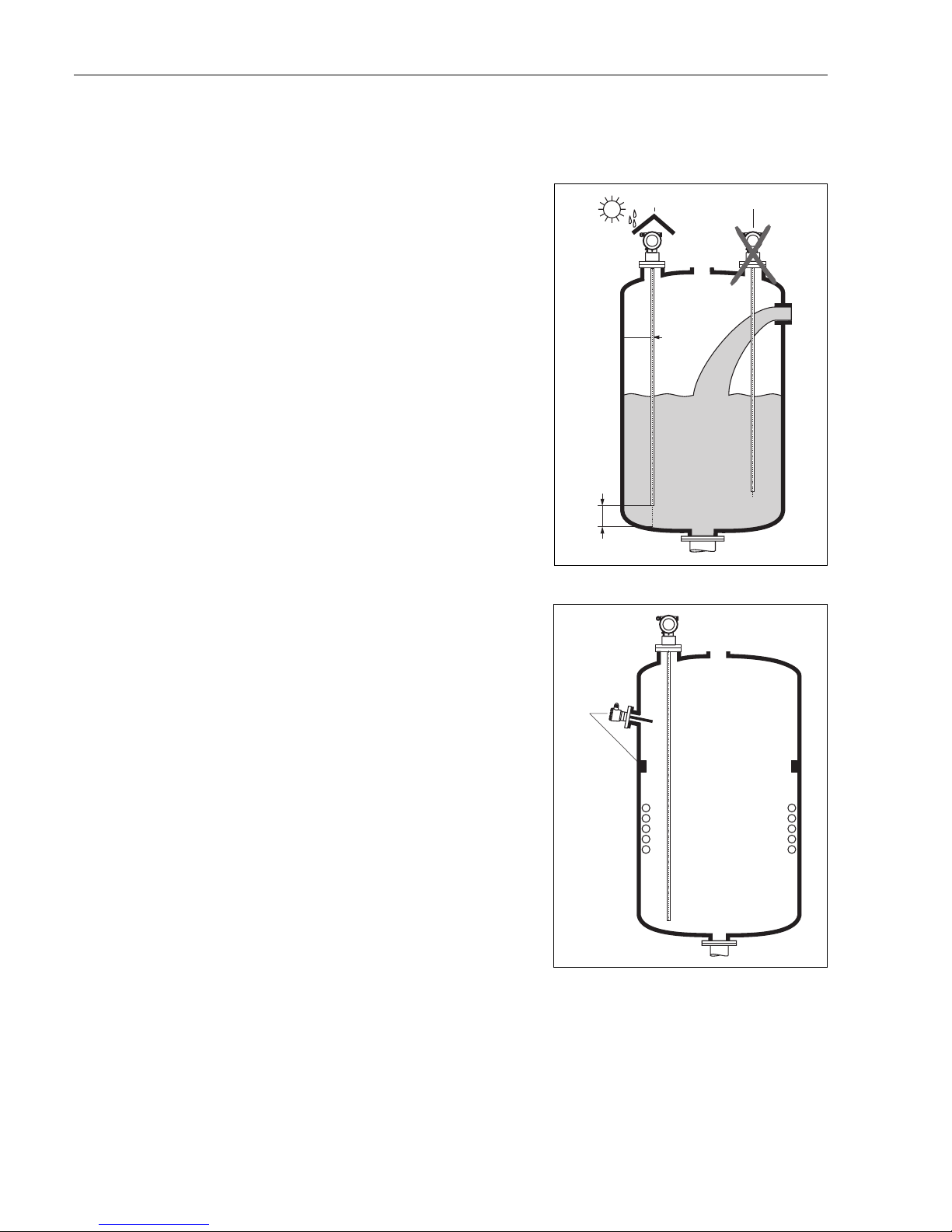
Mounting location
• Do not mount rod or rope probes in the filling
curtain (3).
• Mount rod and rope probes away from the
wall (B) at such a distance that, in the event of
build-up on the wall, there is still a minimum
distance of 100 mm between the probe and
the build-up.
• Mount rod and rope probes as far away as
possible from installed fittings. "Mapping "
must be carried out during commissioning in
the event of distances < 300 mm.
• Minimum distance of probe end to the
container floor (C):
– Rope probe: 150 mm
– Rod probe: 50 mm
• When installing outdoors, it is recommended
that you use a protective cover (1) see
Accessories on → ä 61.
L00-FMP4xxxx-17-00-00-xx-007
B
C
12
Other installations
• Select the mounting location such that the
distance to internals (5) (e.g. limit switch,
struts) > is 300 mm over the entire length of
the probe, also during operation.
• Probe must within the measuring span not
touch any internals during operation.
Optimization options
• Interference echo suppression: Measurement
can be optimised by electronically tuning out
interference echoes.
L00-FMP41Cxx-17-00-0 0-xx-001
5
Page 17
Levelflex M FMP41C with HART/4...20 mA Installation
Endress + Hauser 17
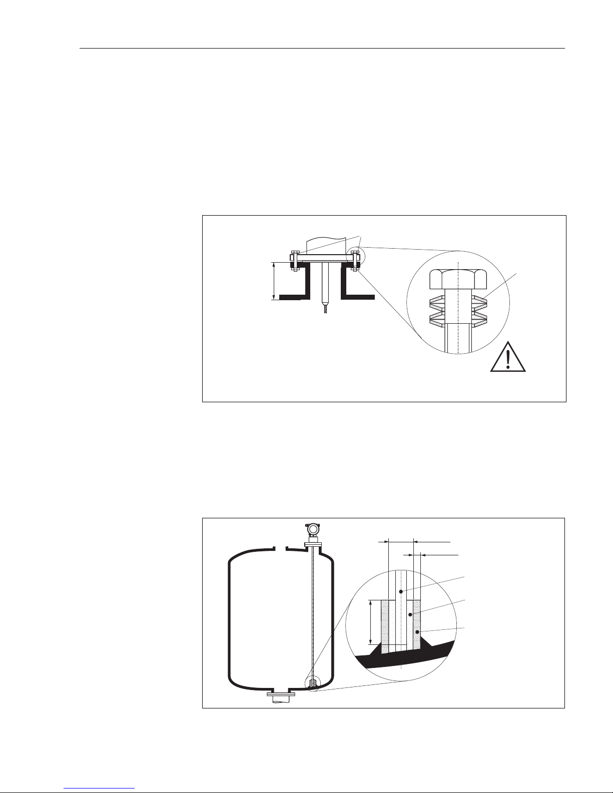
Type of probe mounting
• When installing in plastic tanks, the nozzle must have at least DN50/2". The appropriate flange
must be used as the process connection.
• For nozzles up to 450 mm high, select the length of the centering rod appropriate for the nozzle
height when using rope probes.
• Use spring washers (1) (see Figure below).
Note!
It is recommended to retighten the flange bolts periodically, depending on process temperature
and pressure. Recommended torque: 60...100 Nm.
• After mounting, the housing can be turned 350° in order to simplify access to the display and the
terminal compartment.
L00-FMP41Cxx-17-0 0-00-en-005
The coupling nut must be tightened using a torque of 5 up to a maximum of 10 Nm when installing
the FMP41C in the universal adapter ("Welding boss for adapter 43 mm" → ä 61).
Supporting probes against warping
For WHG or Ex approval:
For probe lengths ≥ 3 m a support is required (see figure).
L00-FMP4xxxx-17-00- 00-en-065
1
£ 450 mm / 18 “
spring washers
Ø <25 mm
>50 mm
Probe rod c
(FMP 41 C)
oated
Short metal pipe
e.g. welded in place
Plastic sleeve
e.g. PTFE, PEEK or PPS
e.g. 3 mm
Page 18

Installation Levelflex M FMP41C with HART/4...20 mA
18 Endress + Hauser
3.3.4 Special instructions
When installing in stirring tanks, observe lateral load of probes. Possibly check whether a noncontact process, ultrasound or radar would not be better suited, above all if the stirrer generates
large mechanical loads on the probe.
Installation in horizontal cylindrical and
standing tanks
• Use a rod probe for measuring ranges up to 4
m. For anything over this or if there is too free
cover space use a rope probe.
• Any distance from wall, as long as occasional
contact is prevented.
L00-FMP4xxxx-17-00-00-yy-049
1
Installation in stilling well or bypass
• Rod and rope probes can also be installed in
pipes (stilling well, bypass).
• When installing in metal pipes up to DN 150/
6", the measuring sensitivity of the device
increases such that liquids as of DK 1.4 can be
measured.
• Welded joints that protrude up to approx. 5
mm/0.2" inwards do not influence
measurement.
L00-FMP4xxxx-17-00-00-yy-023
Page 19

Levelflex M FMP41C with HART/4...20 mA Installation
Endress + Hauser 19
3.3.5 Notes on special installation situations
Installation at an angle
• For mechanical reasons, the probe should be
installed as vertically as possible.
• Installation with a deviation up to approx. 5°
from the vertical axis is permitted for probes
up to approx. 1 m in length.
L00-FMP4xxxx-17-00- 00-de-048
0...5
°
max. 1 m
Fixing rope probe
• The end of the probe needs to be secured if
the probe would otherwise touch the silo
wall, the cone or another part, or the probe
comes closer than 0.5 m to a concrete wall.
This is what the internal thread in the probe
weight is intended for:
– for 4 mm rope: M 14
– for 6 mm rope: M 20
• Preferably use the 6 mm rope probe due to the
higher tensile strength when fixing a rope
probe.
• The fixing must be either reliably grounded or
reliably insulated (see "Accessories" on
→ ä 64)! If it is not possible to mount the
probe weight with a safe earthed connection,
it can be secured using an isolated eyelet,
which is available as an accessory (see
→ ä 64).
• In order to prevent an extremely high tensile
load and the risk of rope crack, the rope has to
be slack. Make the rope longer than the
required measuring range such that there is a
sag in the middle of the rope that is ≥ 1cm/m
(1"/100") of the rope length.
L00-FMP4xxxx-17-00- 00-de-019
sag of the rope:
1cm/m of the rope
length
≥
Page 20

Installation Levelflex M FMP41C with HART/4...20 mA
20 Endress + Hauser
3.3.6 Installation for difficult to access process connections
Installation with remote electronic
• Follow installation instructions on → ä 16
• Mount housing on a wall or pipe as shown in the diagram.
L00-FMP4xxxx-17-00- 00-en-015
!
Note!
The protective hose cannot be disassembled at these points (1).
The ambient temperature for the connecting line (2) between the probe and the electronics must
not be greater than 105°C. The version with remote electronics consists of the probe, a connecting
cable and the housing. If they are ordered as a complete unit they will be delivered assembled and
cannot be separated.
150
ENDRESS+HAUSER
Levelflex M
65 78
Ø 129
85
150
ENDRESS+HAUSER
Levelflex M
65 78
Ø 129
85
52
52
150
max. 80
min. 30
96
94
94
88
88
123
2765
112
190
≥75
Ø 76
1
1
4 x Ø 8,5
1
1
2
pipe
wall
Note min.
bend radius!
Ø 21.3
Page 21

Levelflex M FMP41C with HART/4...20 mA Installation
Endress + Hauser 21
3.4 Turn housing
After mounting, the housing can be turned 350° in order to simplify access to the display and the
terminal compartment. Proceed as follows to turn the housing to the required position:
• Undo the fixing screws (1)
• Turn the housing (2) in the required direction
• Tighten up the fixing screws (1).
L00-FMP41Cxx-17-00 -00-de-002
3.5 Post-installation check
After the measuring instrument has been installed, perform the following checks:
• Is the measuring instrument damaged (visual check)?
• Does the measuring instrument correspond to the measuring point specifications such as process
temperature/pressure, ambient temperature, measuring range, etc.?
• Are the measuring point number and labeling correct (visual check)?
• Is the measuring instrument adequately protected against rain and direct sunlight (see → ä 61)?
90°90
°
90°90
°
90°90
°
1
1
2
2
F12/F23 housing T12 housing
allen key
4 mm/0.1”
Page 22

Wiring Levelflex M FMP41C with HART/4...20 mA
22 Endress + Hauser
4 Wiring
4.1 Quick wiring guide
Wiring in F12/F23 housing
L00-FMP41Cxx-04-00-0 0-en-001
Made in Germany
D-79689 Maulburg
Dat./Insp.:
Order Code:
IP68 / NEMA 6P
Ser.-No.:
4-wire
ENDRESS+HAUSER
t>85°C
TA > 7 0°C:
D01301-A
if modification
see sep. label
X=
Patents
LEVELFLEX-M
90 … 253 VAC 1VA
10,5 … 32VDC1W
16 … 3 VDC 0,8W
Profibus PA
Foundation Fieldbus
LN= PN=
4 … 20 mA HART 2-wire
1234
#
4
5
6
2
3
7
7
1
7
8
-
-
"
56
I+ I-
1
2
L-
L+
12
L1/L+ N/L-
3
4
I+
I-
E
N
D
R
E
S
S
+
H
A
U
S
E
R
ENDRESS+HAUSER
Sealed terminal
compartment
Before connection please note the following:
The power supply must be identical to the data on the
nameplate (1).
Switch off power supply before connecting up the device.
Connect Equipotential bonding to transmitter
ground terminal (7) before connecting up the device.
Tighten the locking screw (8):
It forms the connection between the probe and the housing
ground potential.
●
●
●
●
When you use the measuring system in hazardous areas, make sure you comply with
national standards and the specifications in the safety instructions (XA’s).
Make sure you use the specific cable gland.
On devices supplied with a certificate, the explosion protection
is designed as follows:
Housing F12/F23 - EEx ia:
Power supply must be intrinsically safe (not for dust-Ex).
The electronics and the current output are galvanically
separated from the probe circuit.
●
●
Connect up the Levelflex M as follows:
Unscrew housing cover (2).
Remove any display (3) if fitted.
Remove cover plate from terminal compartment (4).
Pull out terminal module slightly using "pulling loop" (only 2-wire).
Only ground screening of the line (7) on sensor side.
Make connection (see pin assignment).
Re-insert terminal module.
Tighten cable gland (6). Max. torque 10...12 Nm!
Tighten screws on cover plate (4).
Insert display if fitted.
Screw on housing cover (2).
(on dust-Ex torque 40 Nm).
Switch on power supply.
●
●
●
●
●
●
●
●
●
●
●
●
≈
Insert cable (5) through gland (6).
A standard installation cable is sufficient if only the analogue signal is
used. Use a screened cable when working with a superimposed
communications signal (HART).
Unplug display connector!
Caution!
Note!
plant
ground
test sockets
(output current)
power power
display unit,
recorder, PCS
2-wire-version 4-wire-version
If 4-wire for dust-Ex-applications is used,
the current output is .intrinsically save
AC / DCDC
plant
ground
0...20mA
Page 23

Levelflex M FMP41C with HART/4...20 mA Wiring
Endress + Hauser 23
Wiring in T12 housing
L00-FMP41Cxx-04-0 0-00-en-002
Made in Germany
D-79689 Maulburg
Dat./Insp.:
Order Code:
IP68 / NEMA 6P
Ser.-No.:
4-wire
ENDRESS+HAUSER
t>85°C
TA > 7 0°C:
D01301-A
if modification
see sep. label
X=
Patents
LEVELFLEX-M
90 … 253 V AC 1VA
10,5 … 32VDC1W
16 … 3 V DC 0,8W
Profibus PA
Foundation Fieldbus
LN= PN=
4 … 20 mA HART 2-wire
2
-
-
1234
4
3
1
5
1
2
L-
L+
7
8
3
4
I+
I-
Caution!
"
Before connection please note the following:
The power supply must be identical to the data on the
nameplate (1).
Switch off power supply before connecting up the device.
Connect Equipotential bonding to transmitter
ground terminal (7) before connecting up the device.
Tighten the locking screw (8):
It forms the connection between the probe and the housing
ground potential.
●
●
●
●
When you use the measuring system in hazardous areas, make sure you comply with
national standards and the specifications in the safety instructions (XA’s).
Make sure you use the specific cable gland.
Connect up the Levelflex M as follows:
Before unscrew housing cover (2) at seperate connection room
turn off the power supply!
Insert cable (3) through gland (4).
Only ground screening of the line (5) on sensor side.
Make connection (see pin assignment).
Tighten cable gland (4). Max. torque 10...12 Nm!
Screw on housing cover (2)
(on dust-Ex torque 40 Nm).
Switch on power supply.
●
●
●
●
●
≈
A standard installation cable is sufficient if only the analogue signal is
used. Use a screened cable when working with a superimposed
communications signal (HART).
plant
ground
test sockets
(output current)
power
2-wire-version
Page 24

Wiring Levelflex M FMP41C with HART/4...20 mA
24 Endress + Hauser
4.2 Connecting the measuring unit
Terminal compartment
Three housings are available:
• Aluminium housing F12 with additionally sealed terminal compartment for:
–standard,
– EEx ia.
• Aluminium housing T12 with separate terminal compartment for:
–standard,
– EEx e,
– EEx d
– EEX ia (with overvoltage protection).
• Stainless steel 316L housing F23 for:
–standard,
– EEx ia.
After mounting, the housing can be turned 350° in order to simplify access to the display and the
terminal compartment.
L00-FMR2xxxx-04-00-0 0-en-019
The instrument data are given on the nameplate together with important information regarding the
analog output and voltage supply. Housing orientation regarding the wiring see "Turn housing" on
→ ä 21.
Load HART
Minimum load for Hart communication: 250 Ω
Ground connection
It is necessary to make a good ground connection to the ground terminal on the outside of the
housing, in order to achieve EMC security.
Cable gland
Terminals
for wire cross-sections of 0.5...2.5 mm
2
1 1
2 2
3 3
4 4
1
2
3
4
sealed terminal
compartment
F12 housing F23 housing
T12 housing
Type Clamping area
Standard, EEx ia, IS Plastic M20x1.5 5...10 mm
EEx em, EEx nA Metal M20x1.5 7...10.5 mm
Page 25

Levelflex M FMP41C with HART/4...20 mA Wiring
Endress + Hauser 25
Cable entry
Cable gland: M20x1.5
Cable entry: G ½ or ½ NPT
Supply voltage
HART, 2-wire
The following values are the voltages across the terminals directly at the instrument:
HART residual ripple, 2-wire: U
ss
≤ 200 mV
HART, 4-wire active
HART residual ripple, 4-wire, DC version: U
ss
= 2 V, voltage incl. ripple within the permitted
voltage (10.5...32 V).
Power consumption
min. 60 mW, max. 900 mW
Current consumption
Communication
Current
consumption
Terminal voltage
minimal maximal
HART
standard
4mA 16V 36V
20 mA 7.5 V 36 V
EEx ia
4mA 16V 30V
20 mA 7.5 V 30 V
EEx em
EEx d
4mA 16V 30V
20 mA 11 V 30 V
Fixed current, adjustable
e.g. for solar power
operation (measured
value transferred at
HART)
standard 11 mA 10 V 36 V
EEx ia 11 mA 10 V 30 V
Fixed current for HART
Multidrop mode
standard 4 mA
1)
1) Start up current 11 mA.
16 V 36 V
EEx ia 4 mA
1)
16 V 30 V
Version Voltage Max. load
DC 10.5...32 V 600 Ω
AC 85...253 V 600 Ω
Communication
Current
consumption
Current consumption
Power consumption
HART, 2-wire 3.6…22 mA —
HART, 4-wire (90...250 V
AC
) 2.4...22 mA ~ 3...6 mA / ~ 3.5 VA
HART, 4-wire (10,5...32 V
DC
) 2.4...22 mA ~ 100 mA / ~ 1 W
Page 26

Wiring Levelflex M FMP41C with HART/4...20 mA
26 Endress + Hauser
Overvoltage protection
If the measuring device is used for the level measurement in flammable liquids which requires the
use of an overvoltage protection according to DIN EN 60079-14, standard for testprocedures DIN
IEC 60060-1 (10 kA, Puls 8/20 µs) it has to be ensured that
• the measuring device with integrated overvoltage protection with gas discharge tubes within the
T12-enclosure is used, refer to product overview on → ä 8
or
• this protection is achieved by the use of other appropriate measures (external protection devices
e.g. HAW262Z).
4.2.1 HART connection with Endress+Hauser RMA422 / RN221N
L00-FMR2xxxx-04-00-0 0-en-009
4.2.2 HART connection with other supplies
L00-FMR2xxxx-04-00-0 0-en-008
4...20 mA
1
234
ENDRESS + HAUSER
RMA 422
Commubox
FXA1
91/
FXA1
95
RMA422
RN221N
HART
DXR375
1
# % &
Copy
G H I
P Q R S
, ( )‘
A B C
Paste
Page
On
Page
Up
DeleteBksp
Insert
J K L
T UV
_ < >
D E F
Hot Key
+ Hot Key
M N O
W XY Z
+ * /
4
7
.
2
5
8
0
375
FIELD COMMUNICATOR
3
6
9
-
FMP40:LIC0001
ONLINE
1 GROUP SELECT
2 PV 8.7 m
HELP SAVE
dsdmdm
df das.
asdas fa
asas la.
FXA193
- ToF Tool Fieldtool
Package
- FieldCare
- ToF Tool Fieldtool
Package
- FieldCare
1
234
HART
DXR375
1
# % &
Copy
G H I
P Q R S
, ( )‘
A B C
Paste
Page
On
Page
Up
DeleteBksp
Insert
J K L
T UV
_ < >
D E F
Hot Key
+ Hot Key
M N O
W XY Z
+ * /
4
7
.
2
5
8
0
375
FIELD COMMUNICATOR
3
6
9
-
FMP40:LIC0001
ONLINE
1 GROUP SELECT
2 PV 8.7 m
HELP SAVE
dsdmdm
df das.
asdas fa
asas la.
- ToFTool Fieldtool
Package
- FieldCare
- ToFTool Fieldtool
Package
- Fieldcare
Commubox
FXA191/FXA195
FXA193
≥Ω250
PLC
DC power supply
unit
or
4...20 mA
Page 27

Levelflex M FMP41C with HART/4...20 mA Wiring
Endress + Hauser 27
"
Caution!
If the HART communication resistor is not built into the supply unit and the HART interface is to
be used, it is necessary to insert a communication resistor of 250 Ω into the 2-wire line.
4.3 Recommended connection
4.3.1 Equipotential bonding
Connect the Equipotential bonding to the external ground terminal (1) of the transmitter.
L00-FMP41Cxx-17-0 0-00-en-003
4.3.2 Wiring screened cable
"
Caution!
In Ex applications, the instrument must only be grounded on the sensor side. Further safety
instructions are given in the separate documentation for applications in explosion hazardous areas.
4.4 Degree of protection
• with closed housing tested according to
– IP68, NEMA6P (24 h at 1.83 m under water surface)
– IP66, NEMA4X
• with open housing: IP20, NEMA1 (also ingress protection of the display)
4.5 Post-connection check
After wiring the measuring instrument, perform the following checks:
• Is the terminal allocation correct (see → ä 22 and → ä 23)?
• Is the cable gland tight?
• Is the housing cover screwed tight?
• If auxiliary power is available:
Is the instrument ready for operation and is the liquid crystal display visible?
1
1
F12/F23 housing T12 housing
Page 28

Operation Levelflex M FMP41C with HART/4...20 mA
28 Endress + Hauser
5Operation
5.1 Quick operation guide
L00-FMP4xxxx-19-00- 00-en-001
X
X
X
X
S
SS
O
OO
FF
>3 s
F
...
2x
ENDRESS + HAUSER
E
+
–
...
...
Selection and configuration in Operation menu:
Group Selection
Function Group
unction
Note!
Selection menus:
function
Typing in numerals and text:
numeral / text
function
function
Group selection
Measured value display
1.) Change from Measured Value Display to by pressing
2.) Press or to select the required (e.g.. "basic setup (00)") and confirm by pressing
(e.g. "tank shape (002)") is selected.
The active selection is marked by a in front of the menu text.
3.) Activate Edit mode with or .
a) Select the required in selected (e.g. "tank shape (002)") with or .
b) confirms selection appears in front of the selected parameter
c) confirms the edited value system quits Edit mode
d) / (= ) interrupts selection system quits Edit mode
a) Press or to edit the first character of the (e.g. "empty calibr. (005)")
b) positions the cursor at the next character (a) until you have completed your input
c) if a symbol appears at the cursor, press to accept the value entered
system quits Edit mode
d) / (= ) interrupts the input,
4) Press to select the next (e.g. "medium property (003)")
5) Press / (= ) once return to previous (e.g. "tank shape (002)")
Press / (= ) twice return to
6) Press / (= ) to return to
F
SO
O
SO
F
S
X
S
F
S
F
F
OS X
OS
F
OX
F
OS X
OS
OX
➜✔
➜
➜
➜
➜
➜
➜
First f
continue with
system quits Edit mode
➜
✔
Parameter
Return to
Group Selection
basic setup
safety settings
linearisation
extended calibr.
tank shape
Standard
aluminium tank
plastic tank
bypass / pipe
coax probe
concrete wall
medium property
Page 29

Levelflex M FMP41C with HART/4...20 mA Operation
Endress + Hauser 29
5.1.1 General structure of the operating menu
The operating menu is made up of two levels:
• Function groups (00, 01, 03, …, 0C, 0D):
The individual operating options of the instrument are split up roughly into different function
groups. The function groups that are available include, e.g.: "basic setup", "safety settings.",
"output", "display", etc.
• Functions (001, 002, 003, …, 0D8, 0D9):
Each function group consists of one or more functions. The functions perform the actual operation
or parameterisation of the instrument. Numerical values can be entered here and parameters can
be selected and saved. The available functions of the “basic setup" (00) function group include,
e.g.: "tank properties" (002), "medium property" (003), "process cond." (004), "empty
calibr." (005), etc.
If, for example, the application of the instrument is to be changed, carry out the following
procedure:
1. Select the “basic setup" (00) function group.
2. Select the "tank properties" (002) function (where the existing tank shape is selected).
5.1.2 Identifying the functions
For simple orientation within the function menus, for each function a position is shown on the
display.
L00-FMRxxxxx-07-00-00-en-005
The first two digits identify the function group:
The third digit numbers the individual functions within the function group:
Here after the position is always given in brackets (e.g. "tank properties" (002)) after the described
function.
• basic setup 00
• safety settings 01
• linearisation 04
...
• basic setup 00 → • tank properties 002
• medium property 003
• process cond. 004
...
Page 30

Operation Levelflex M FMP41C with HART/4...20 mA
30 Endress + Hauser
5.2 Display and operating elements
Four lines with 20 characters each. Display contrast adjustable through key combination.
L00-FMxxxxxx-07-00-0 0-en-001
The VU331 LCD display can be removed to ease operation by simply pressing the snap-fit (see
graphic above). It is connected to the device by means of a 500 mm cable.
5.2.1 Display
Liquid crystal display (LCD):
L00-FMxxxxxx-07-00-0 0-en-001
Fig. 3: Display
ENDRESS + HAUSER
E
+
–
E
N
D
R
E
S
S
+
H
A
U
S
E
R
M
I
C
R
O
P
I
L
O
T
I
I
ENDR
E
SS+
H
A
U
S
ER
MICR
O
P
I
L
O
TII
IP6
5
IP65
O
r
d
e
r
C
o
d
e
:
S
e
r
.
N
o
.
:
Order
Co
d
e:
S
er.-No.
:
M
e
s
s
b
e
r
e
i
c
h
M
e
a
s
u
r
i
n
g
r
a
n
g
e
M
es
s
b
er
e
i
c
h
Me
a
s
urin
g
range
U
1
6
.
.
.
3
6
V
D
C
4
.
.
.
2
0
m
A
U
16...36
V
DC
4...20
mA
m
a
x
.
2
0
m
m
ax
.
2
0
m
MadeinGermany Maulburg
MadeinGermany Maulburg
T>
7
0
°
C
:
A
t
>
8
5
°
C
T>
7
0°C:
A
t
>8
5
°C
LCD
(liquid crystal display)
Symbols
3 keys
snap-fit
X
X
X
X
S
S
O
O
FF
F
F
HOME
FG00
F000 F001 F002 F003 F004 ...
FG01
FG02
FG03
FG04
FG05
FG06
FG07
...
+21mV 09C
10.002.305m
0.00
ENDRESS + HAUSER
E
+
–
Headline Position indicator
Main value
Unit
Symbol
Selection list
Function groups -> Functions
Help text
Envelope
curve
Page 31

Levelflex M FMP41C with HART/4...20 mA Operation
Endress + Hauser 31
5.2.2 Display symbols
The following table describes the symbols that appear on the liquid crystal display:
5.2.3 Key assignment
The operating elements are located inside the housing and are accessible for operation by opening
the lid of the housing.
Function of the keys
Sybmol Meaning
ALARM_SYMBOL
This alarm symbol appears when the instrument is in an alarm state. If the symbol flashes, this indicates a
warning.
LOCK_SYMBOL
This lock symbol appears when the instrument is locked,i.e. if no input is possible.
COM_SYMBOL
This communication symbol appears when a data transmission via e.g. HART, PROFIBUS PA or
FOUNDATION Fieldbus is in progress.
Key(s) Meaning
O
or
V
Navigate upwards in the selection list
Edit numeric value within a function
S
or
W
Navigate downwards in the selection list
Edit numeric value within a function
X
or
Z
Navigate to the left within a function group
F
Navigate to the right within a function group, confirmation.
O
and
F
or
S
and
F
Contrast settings of the LCD
O
and S and
F
Hardware lock / unlock
After a hardware lock, an operation of the instrument via display or
communication is not possible!
The hardware can only be unlocked via the display. An unlock parameter must
be entered to do so.
Page 32

Operation Levelflex M FMP41C with HART/4...20 mA
32 Endress + Hauser
5.3 Local operation
5.3.1 Locking of the configuration mode
The Levelflex can be protected in two ways against unauthorised changing of instrument data,
numerical values or factory settings:
"unlock parameter" (0A4):
A value <> 100 (e.g. 99) must be entered in "unlock parameter" (0A4) in the
"diagnostics" (0A) function group. The lock is shown on the display by the symbol and can be
released again either via the display or by communication.
Hardware lock:
The instrument is locked by pressing the
O
and S and F keys at the same time. The lock is shown
on the display by the symbol and can only be unlocked again
via the display by pressing the
O
and S and F keys at the same time again. It is not possible to
unlock the hardware by communication. All parameters can be displayed even if the instrument is
locked.
⇒
O
and S and F press simultaneous
⇓
⇓
The LOCK_SYMBOL appears on the LCD.
ENDRESS + HAUSER
E
+
–
Page 33

Levelflex M FMP41C with HART/4...20 mA Operation
Endress + Hauser 33
5.3.2 Unlocking of configuration mode
If an attempt is made to change parameters when the instrument is locked, the user is automatically
requested to unlock the instrument:
"unlock parameter" (0A4):
By entering the unlock parameter (on the display or via communication)
100 = for HART devices
the Levelflex is released for operation.
Hardware unlock:
After pressing the
O
and S and F keys at the same time, the user is asked to enter the unlock
parameter
100 = for HART devices
"
Caution!
Changing certain parameters such as all sensor characteristics, for example, influences numerous
functions of the entire measuring system, particularly measuring accuracy. There is no need to
change these parameters under normal circumstances and consequently, they are protected by a
special code known only to the Endress+Hauser service organization. Please contact
Endress+Hauser if you have any questions.
⇒
O
and S and F press simultaneous
⇓
Please enter unlock code and confirm with F.
⇓
ENDRESS + HAUSER
E
+
–
Page 34

Operation Levelflex M FMP41C with HART/4...20 mA
34 Endress + Hauser
5.3.3 Factory settings (Reset)
"
Caution!
A reset sets the instrument back to the factory settings. This can lead to an impairment of the
measurement. Generally, you should perform a basic setup again following a reset.
A reset is only necessary:
• if the instrument no longer functions
• if the instrument must be moved from one measuring point to another
• if the instrument is being de-installed /put into storage/installed
User input ("reset" (0A3)):
• 333 = customer parameters
333 = reset customer parameters
This reset is recommended whenever an instrument with an unknown 'history' is to be used in an
application:
• The Levelflex is reset to the default values.
• The customer specific tank map is not deleted.
• The mapping can also be deleted in the "cust. tank map" (055) function of the "extended
calibr" (05) function group.
• A linearisation is switched to "linear" although the table values are retained. The table can be
reactivated in the "linearisation" (04) function group.
List of functions that are affected by a reset:
A complete “basic setup" (00) must be activated.
⇒
ENDRESS + HAUSER
E
+
–
• tank properties (002)
•medium cond. (003)
• process proper. (004)
• empty calibr. (005)
• full calibr. (006)
• output on alarm (010)
• output on alarm (011)
• outp. echo loss (012)
• ramp %span/min (013)
• delay time (014)
• safety distance. (015)
• in safety dist. (016)
• overspill protection (018)
• end of probe (030)
• level/ullage (040)
• linearisation (041)
• customer unit (042)
• max. scale (046)
• diameter vessel (047)
• check distance (051)
• range of mapping (052)
• start mapping (053)
• offset (057)
• output damping (058)
• low output limit (062)
• curr. output mode (063)
• fixed cur. value (064)
•4mA value (068)
• language (092)
• back to home (093)
• format display (094)
• no of decimals (095)
• sep. character (096)
• unlock parameter (0A4)
Page 35

Levelflex M FMP41C with HART/4...20 mA Operation
Endress + Hauser 35
5.4 Display and acknowledging error messages
Type of error
Errors that occur during commissioning or measuring are displayed immediately on the local
display. If two or more system or process errors occur, the error with the highest priority is the one
shown on the display.
The measuring system distinguishes between two types of error:
• A (Alarm):
Instrument goes into a defined state (e.g. MAX 22 mA)
Indicated by a constant symbol.
(For a description of the codes see → ä 66)
• W (Warning):
Instrument continue measuring, error message is displayed.
Indicated by a flashing symbol.
(For a description of the codes see → ä 66)
• E (Alarm / Warning):
Configurable (e.g. loss of echo, level within the safety distance)
Indicated by a constant/flashing symbol.
(For a description of the codes see → ä 66)
Error messages
Error messages appear as four lines of plain text on the display. In addition, a unique error code is
also output. A description of the error codes is given on → ä 66.
•The "diagnostics" (0A) function group can display current errors as well as the last errors that
occurred.
• If several current errors occur, use
O
or S to page through the error messages.
• The last occurring error can be deleted in the "diagnostics" (0A) function group
with the function "clear last error" (0A2).
⇒
ENDRESS + HAUSER
E
+
–
Page 36

Operation Levelflex M FMP41C with HART/4...20 mA
36 Endress + Hauser
5.5 HART communication
Apart from local operation, you can also parameterise the measuring instrument and view measured
values by means of a HART protocol. There are two options available for operation:
• Operation via the universal handheld operating unit, the HART Communicator
DXR375.
• Operation via the Personal Computer (PC) using the operating program
(e.g. ToF Tool) (For connections, see → ä 26).
5.5.1 Operation with handheld unit Field Communicator DXR375
All device functions can be adjusted via a menu operation with the handheld unit DXR375.
L00-FMR2xxxx-07-00-00-yy-007
!
Note!
• Further information on the HART handheld unit is given in the respective operating manual
included in the transport bag of the DXR375.
5.5.2 ToF Tool operating program
The ToF Tool is a graphical operation software for instruments from Endress+Hauser. It is used to
support commissioning, securing of data, signal analysis and documentation of the instruments. It
is compatible with the following operating systems: WinNT4.0, Win2000 and WinXP.
The ToF Tool supports the following functions:
• Online configuration of transmitters
• Signal analysis via envelope curve
• Linearisation table (graphically supported creation, editing, importing and exporting)
• Loading and saving of instrument data (Upload/Download)
• Documentation of measuring point
!
Note!
Further information you may find on the CD-ROM, which is enclosed to the instrument.
1
# % &
Copy
G H I
P Q R S
, ( )‘
A B C
Paste
Page
On
Page
Up
DeleteBksp
Insert
J K L
T UV
_ < >
D E F
Hot Key
+ Hot Key
M N O
W XY Z
+ * /
4
7
.
2
5
8
0
375
FIELD COMMUNICATOR
3
6
9
-
9
6
FMR231:LIC0001
ONLINE
1 GROUP SELECT
2 PV 8.7 m
HELP SAVE
dsdmdm
df das.
asdas fa
asas la.
Page
On
Page
Up
Bksp
Delete
Delete
FMR231: LIC0001
ONLINE
1 GROUP SELECTION
2 PV 8.7 m
HELP SAVE
dsdmdm
df das.
asdas fa
asas la.
FMR231: LIC0001
GROUP SELECTION
HOMESAVE
dsdmdm
df das.
asdas fa
asas la.
H
FMR231: LIC0001
HOMESAVE
dsdmdm
df das.
asdas fa
asas la.
H
Bksp
1 BASIC SETUP
2 SAFETY SETTINGS
BASIC SETUP
1 MEASURED VALUE
4 PROCESS COND.
5 EMPTY CALIBR.
3 MEDIUM PROPERTY
4 EXTENDED CALIB.
5 OUTPUT
3 LINEARISATION
2 TANK SHAPE
Page 37

Levelflex M FMP41C with HART/4...20 mA Operation
Endress + Hauser 37
Menu-guided commissioning
L00-FMP4xxxx-20-00- 00-de-002
Signal analysis via envelope curve:
L00-FMP4xxxx-20-00- 00-de-007
Connection options
• HART mit Commubox FXA191/FXA195
• Service-interface with adapter FXA193 (RS232C) or FXA291 and ToF Adapter FXA291 (USB)
Page 38

Commissioning Levelflex M FMP41C with HART/4...20 mA
38 Endress + Hauser
6 Commissioning
6.1 Function check
Make sure that all final checks have been completed before you start up your measuring point:
• Checklist “Post-installation check” (→ ä 21).
• Checklist “Post-connection check” (→ ä 21).
6.2 Switching on the measuring device
When the instrument is switched on for the first time, the following messages appear on the display:
⇒
⇓
After 5 s, the following message appears
⇓
After 5 s, the following message appears (e.g. on HART
devices)
⇓
After 5 s or after you have pressed F the following
message appears
Select the language
(this message appears the first time the instrument is
switched on)
⇓
Select the basic unit
(this message appears the first time the instrument is
switched on)
⇓
The current measured value is displayed
⇓
After F is pressed, you reach the group selection.
This selection enables you to perform the basic setup
ENDRESS + HAUSER
E
+
–
Page 39

Levelflex M FMP41C with HART/4...20 mA Commissioning
Endress + Hauser 39
6.3 Basic Setup
L00-FMP41Cxx-19-0 0-00-en-001
SD
UB
F
L
D
E
LN
LB
flange:
referencepoint of
measurement
tank shape
Standard
measuring cond.
Unknown
measuring cond.
Standard
mapping
safety settings
linearisation
extended calibr.
...
empty calibr.
full calibr.
(description see BA 245F)
basic setup (standard)
option
E = empty calibr. (= zero) LN = probe length
setting in 005 setting in 033
F = full calibr. (= span) UB = upper blocking distance
setting in 006 setting in 059
D = distance (distance flange / product) SD = safety distance
display in 0A5 setting in 015
L = level LB = lower blocking
display in 0A6 distance
Page 40

Commissioning Levelflex M FMP41C with HART/4...20 mA
40 Endress + Hauser
The basic setup is sufficient for successful commissioning in most applications.
The Levelflex is initially adjusted at the factory to the probe length ordered, so that in most cases
only the application parameters, that automatically adapt the device to the measuring conditions,
need to be entered. For models with current output, the factory adjustment for zero point and span
is F 4 mA and 20 mA, for digital outputs and the display module 0 % and 100 %.A linearisation
function with max. 32 points, that is based on a manually or semi-automatically input table, can be
activated on-site or via remote operation. This function enables, for example, the conversion of the
level into units of volume or weight.
!
Note!
The Levelflex M allows to check for broken probe. On delivery, this function is switched off,
because otherwise shortening of the probe would be mistaken for a broken probe.
In order to activate this function, perform the following steps:
1. With the probe uncovered, perform a mapping ("range of mapping" (052) and "start
mapping." (053)).
2. Activate the "broken probe det" (019) function in the "safety settings" (01) function
group.
Complex measuring operations necessitate additional functions that the user can use to customise
the Levelflex as necessary to suit his specific requirements. The functions available to do this are
described in detail in the BA245F – "Description of the instrument functions" on the enclosed CDROM.
Comply with the following instructions when configuring the functions in the "basic setup" (00):
• Select the functions as described on → ä 28.
• Certain functions (e.g. starting an interference echo mapping (053)) prompt you to confirm your
data entries. Press
O
or S to select "YES" and press F to confirm. The function is now started.
• If you do not press a key during a configurable time period (→ function group "display (09)") ,
an automatic return is made to the home position (measured value display).
!
Note!
• The instrument continues to measure while data entry is in progress, i.e. the current measured
values are output via the signal outputs in the normal way.
• If the envelope curve mode is active on the display, the measured values are updated in a slower
cycle time. Thus, it is advisable to leave the envelope curve mode after the measuring point has
been optimised.
• If the power supply fails, all preset and parameterised values remain safely stored in the EEPROM.
"
Caution!
All functions are described in detail, as is the overview of the operating menu itself, in the manual
BA245F – "Description of the instrument functions" on the enclosed CD-ROM.
Page 41

Levelflex M FMP41C with HART/4...20 mA Commissioning
Endress + Hauser 41
6.4 Basic Setup with the VU331
Function "measured value" (000)
This function displays the current measured value in the selected unit
(see "customer unit" (042)) function). The number of digits after decimal point can be selected in
the "no.of decimals" (095) function.
6.4.1 Function group "basic setup" (00)
Function "tank properties" (002)
This function is used to select the tank properties.
Selection:
• standard
• aluminium tank
• plastic tank
• bypass / pipe
• coax probe
• concrete wall
standard
The "standard" option is recommended for normal containers for rod and rope probes.
aluminium tank
The "aluminium tank" option is designed especially for high aluminium silos that cause an
increased level of noise when empty. This option is only useful for probes
longer than (< 4 m). For short probes (< 4 m) select the "standard" option!
!
Note!
If "aluminium tank" is selected, the device calibrates of its own accord when first filled, depending
on the medium's properties. Slope errors can, therefore, occur when beginning the first filling
procedure.
plastic tank
Select the "plastic tank" option when installing probes in wood or plastic containers without
metallic surfaces at the process connection (see installation in plastic containers). When using a
metallic surface at the process connection, the "standard" option is sufficient!
!
Note!
In principle the employment of a metallic surface area should be preferred at the process connection!
⇒
ENDRESS + HAUSER
E
+
–
⇒
ENDRESS + HAUSER
E
+
–
⇒
ENDRESS + HAUSER
E
+
–
Page 42

Commissioning Levelflex M FMP41C with HART/4...20 mA
42 Endress + Hauser
bypass / pipe
The "bypass / pipe" option is designed especially for the installation of probes in a bypass or a
stilling well. If this option is selected, the upper blocking distance is preset to 100 mm.
coax probe
Select the "coax probe" option when using a coaxial probe. When this setting is made, the
evaluation is adapted to the high sensitivity of the coax probe. This option should, therefore, not be
selected when using rope or rod probes.
concrete wall
The "concrete wall" option takes into account the signal-damping property of concrete walls when
mounting with < 1 m distance to the wall.
Function "medium property" (003)
This function is used to select the dielectric constant.
Selection:
• unknown
• 1.4 ... 1.6 (1,4 for installation in metallic pipes)
• 1.6 ... 1.9
• 1.9 ... 2.5
• 2.5 ... 4.0
• 4.0 ... 7.0
•> 7.0
The lower group applies to very loose or loosened bulk solids. Reduction of the max. possible
measuring range by means of:
• extremely loose surfaces of bulk solids, e.g. bulk solids with low piled density when filled
pneumatically.
• Build-up, primarily of moist products.
!
Note!
Due to the high diffusion rate of ammonia it is recommended to use the FMP45 with gas-tight
bushing for measurements in this medium.
⇒
ENDRESS + HAUSER
E
+
–
Media group DC (εr) Typical liquids Typ. measuring range
1 1.4...1.6 – Condensed gases, e.g. N
2
, CO2 4 m (157"), when installed in metallic pipes
2 1.6...1.9
– Liquefied gas, e.g. Propane
–Solvent
– Frigen / Freon
–Palm oil
9 m (354")
3 1.9...2.5 – Mineral oils, fuels 12 m (472")
4 2.5...4
– Benzene, styrene, toluene
–Furan
– Naphthalene
16 m (629")
5 4...7
– Chlorobenzene, chloroform
– Cellulose spray
– Isocyanate, aniline
25 m (984")
6 >7
– Aqueous solutions
–Alcohols
– Acids, alkalis
30 m (1181")
Page 43

Levelflex M FMP41C with HART/4...20 mA Commissioning
Endress + Hauser 43
Function "process propert." (004)
Use this function to adapt the device reaction to the filling speed in the tank. The setting impacts
on an intelligent filter.
Selection:
• standard
• fast change
• slow change
• test:no filter
Function "end of probe" (030)
This function is used to select the polarity of the probe end signal when using other Levelflex
models. Only the setting "free " is permitted for the FMP41C.
Selection:
• free
• tie down isol.
1)
•tie down gnd.
1
⇒
ENDRESS + HAUSER
E
+
–
Selection: standard fast change slow change test:no filter
Application: For all normal applications, bulk
solids and fluids at low to
medium filling speed and
sufficiently large tanks.
Small tanks, primarily with
fluids, at high filling speeds.
Applications with strong surface
movement, e.g. caused by
stirrer, primarily large tanks with
slow to medium filling speed.
Shortest reaction time:
• For test purposes
• Measurement in small tanks
at high filling speeds, if "rapid
change" setting is too slow.
2-wire electronics: Dead time: 4 s
Rise time: 18 s
Dead time: 2 s
Rise time: 5 s
Dead time: 6 s
Rise time: 40 s
Dead time: 1 s
Rise time: 0 s
4-wire electronics: Dead time: 2 s
Rise time: 11 s
Dead time: 1 s
Rise time: 3 s
Dead time: 3 s
Rise time: 25 s
Dead time: 0,7 s
Rise time: 0 s
⇒
ENDRESS + HAUSER
E
+
–
1) These settings lead to a false output signal for empty tanks.
Page 44

Commissioning Levelflex M FMP41C with HART/4...20 mA
44 Endress + Hauser
Function "probe length" (031)
Use this function to select whether the probe length was changed after factory calibration. Only then
is it necessary to enter or correct the probe length.
Selection:
• not modified
• modified
!
Note!
If "modified" was selected in the "probe length" (031) function, the probe length is defined in the
next step.
Function "probe" (032)
Use this function to select whether the probe is at the time of the commisioning uncovered or
covered.
If the probe is uncovered, the Levelflex can determine the probe length automatically "determine
length" (034) function. If the probe is covered, a correct entry is required in the "probe length"
(033) function.
Selection:
• free
• covered
Function "probe length" (033)
Use this function, the probe length can be entered manually.
Function "determine length" (034)
Use this function, the probe length can be determined automatically.
Due to the mounting conditions, the automatically determined probe length may be larger than the
actual probe (typically 20 .. 30 mm longer). This has no influence on the measuring accuracy. When
entering the empty value for a linearisation, please use the "empty calibration" instead of the
automatically determined probe length.
Selection:
• length ok
• too short
• too long
⇒
ENDRESS + HAUSER
E
+
–
⇒
ENDRESS + HAUSER
E
+
–
⇒
ENDRESS + HAUSER
E
+
–
⇒
ENDRESS + HAUSER
E
+
–
Page 45

Levelflex M FMP41C with HART/4...20 mA Commissioning
Endress + Hauser 45
After selection "length too short" or "length too long", the calculation of the new value need approx.
10 s.
Function "empty calibr." (005)
This function is used to enter the distance from the flange (reference point of the measurement) to
the minimum level (=zero).
L00-FMP4xxxx-14-00- 06-en-008
Function "full calibr." (006)
This function is used to enter the distance from the minimum level to the maximum level (=span).
⇒
ENDRESS + HAUSER
E
+
–
0%
E
E = empty calibration (= zero)
E
max
= probe length – lower blocking distance
⇒
ENDRESS + HAUSER
E
+
–
Page 46

Commissioning Levelflex M FMP41C with HART/4...20 mA
46 Endress + Hauser
L00-FMP4xxxx-14-00- 06-en-009
!
Note!
The usable measuring range lies between the lower and the upper blocking distance. The values for
empty distance (E) and span (F) can be set independently of this.
Display (008)
The distance measured from the reference point to the product surface and the meas. value
calculated with the aid of the empty adjustment are displayed. Check whether the values
correspond to the actual meas. value or the actual distance. The following cases can occur:
• Distance correct – meas. value correct -> continue with the next function
"check distance" (051).
• Distance correct – meas. value incorrect -> Check "empty calibr." (005)
• Distance incorrect – meas. value incorrect -> continue with the next function
"check distance" (051).
Function "check distance" (051)
This function triggers the mapping of interference echoes. To do so, the measured distance must be
compared with the actual distance to the product surface. The following options are available for
selection:
Selection:
•distance = ok
• dist. too small
• dist. too big
• dist. unknown
• manual
• probe free
100%
0%
F
F = full calibration (= span)
F
max
= E – upper blocking distance
⇒
ENDRESS + HAUSER
E
+
–
⇒
ENDRESS + HAUSER
E
+
–
Page 47

Levelflex M FMP41C with HART/4...20 mA Commissioning
Endress + Hauser 47
L00-FMP4xxxx-14-00- 06-en-010
distance = ok
Use this function at part-covered probe. Choosing function "manual" or "probe free" at free probe.
• mapping is carried out up to the currently measured echo
• The range to be suppressed is suggested in the "range of mapping" (052) function
Anyway, it is wise to carry out a mapping even in this case.
!
Note!
At free probe, the mapping should be confirmed with the choice "probe free".
dist. too small
• At the moment, an interference is being evaluated
• Therefore, a mapping is carried out including the presently measured echoes
• The range to be suppressed is suggested in the "range of mapping" (052) function
dist. too big
• This error cannot be remedied by interference echo mapping
• Check the application parameters (002), (003), (004) and "probe length." (031)
dist. unknown
If the actual distance is not known, no mapping can be carried out.
manual
A mapping is also possible by manual entry of the range to be suppressed. This entry is made in the
"range of mapping" (052) function.
"
Caution!
The range of mapping must end 0.3 m (20") before the echo of the actual level. In case of empty
vessel it is possible to make a map over the whole probe length.
probe free
If the probe is uncovered, mapping is carried out along the whole probe length.
"
Caution!
Only begin mapping in this function if the probe is safely uncovered. Otherwise, the device will not
make correct measurements!
+
+
distance too small distance =ok
Page 48

Commissioning Levelflex M FMP41C with HART/4...20 mA
48 Endress + Hauser
Function "range of mapping" (052)
This function displays the suggested range of mapping. The reference point is always the reference
point of the measurement (→ ä 39). This value can be edited by the operator.
For manual mapping, the default value is 0,3 m.
Function "start mapping" (053)
This function is used to start the interference echo mapping up to the distance given in "range of
mapping" (052).
Selection:
• off: no mapping is carried out
• on: mapping is started
Display (008)
The distance measured from the reference point to the product surface and the meas. value
calculated with the aid of the empty alignment are displayed again. Check whether the values
correspond to the actual meas. value or the actual distance. The following cases can occur:
• Distance correct – meas. value correct -> basic setup completed
• Distance incorrect – meas. value incorrect -> a further interference echo mapping must be
carried out "check distance" (051).
• Distance correct – meas. value incorrect -> check "empty calibr" (005)
!
Note!
After the basic setup, an evaluation of the measurement with the aid of the envelope curve
("envelope curve" (0E) function group) is recommended (→ ä 58).
⇒
ENDRESS + HAUSER
E
+
–
⇒
ENDRESS + HAUSER
E
+
–
⇒
ENDRESS + HAUSER
E
+
–
⇒
⇓
After 3 s, the following message appears
ENDRESS + HAUSER
E
+
–
Page 49

Levelflex M FMP41C with HART/4...20 mA Commissioning
Endress + Hauser 49
6.5 Blocking distance
Function "upper block. dist" (059)
For rod probes and for rope probes with lengths of up to 8 m, the upper blocking distance is preset
to 0.2 m on delivery.
For rope probes with lengths of more than 8 m, the upper blocking distance is preset to 2.5% of the
probe length.
For media with DC > 7, the upper blocking distance for rod and rope probes can be reduced to 0.1
m, if the probe is mounted flush with the wall or in a nozzle of maximum 50 mm.
Blocking distance and measuring range
At the lower end of the probe there is no blocking distance but a transition region with reduced
accuracy, see section "Maximum measured error" on → ä 50.
!
Note!
Within the upper and lower blocking distance, a reliable measurement can not be guaranteed.
For stilling well applications
The upper blocking distance (UB) is preset to 100 mm when the "bypass/pipe" parameter has been
selected in the "tank properties" (002) function.
⇒
ENDRESS + HAUSER
E
+
–
FMP41C
LN [m] UB [m]
min max min
Rod probe 0,3 4 0,2
1)
1) The indicated blocking distances are preset. At media with DC > 7, the upper blocking
distance UB can be reduced to 0.1 mm for rod and rope probes. The upper blocking
distance UB can be entered manually.
Rope probe 130 0,2
1)
Page 50
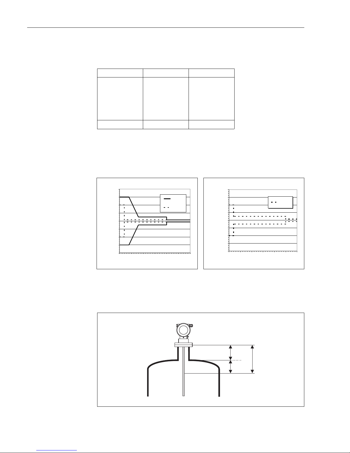
Commissioning Levelflex M FMP41C with HART/4...20 mA
50 Endress + Hauser
Maximum measured error
Typical statements for reference conditions:
DIN EN 61298-2, percentage of the span.
If the reference conditions are not met, the offset/zero arising from the mounting situation may be
up to ±12 mm. This additional offset/zero can be compensated for by entering a correction
(function "offset" (057)) during commissioning.
Differing from this , the following measuring error is present in the vicinity of the probe end:
!
Note!
Please reenter the blocking distance in the function group "extended calibr." (05) function
"upper block.dist" (059) when installing the device in a high nozzle: upper blocking distance (UB)
= nozzle height (H) + 50 mm.
L00-FMP4xxxx-14-00-06-xx-001
Output: digital analogue
sum of non-linearity,
non-repeatability
and hysteresis
measurig range:
–up to 10 m: ±5mm
– > 10 m: ± 0.05 %
for PA coated rope
measuring range:
– up to 5 m: ±5 mm
– > 5 m: ± 0.1 %
± 0.06 %
Offset / Zero ±4 mm ± 0.03 %
L00-FMP4xxxx-05-00- 00-en-001 L00-FMP4xxxx-05-00- 00-en-002
rod probe and coax probe
-80
-60
-40
-20
0
20
40
60
80
0 50 100 150 200 250 300
distance from probe end [mm]
sum of non-linearity, non-repeatability
and hysteresis [mm]
DC = 2
DC > 7
rope probe
-80
-60
-40
-20
0
20
40
60
80
0 50 100 150 200 250 300
distance from probe end [mm]
sum of non-linearity, non-repeatability
and hysteresis [mm]
DC > 7
UB
H
50
Page 51

Levelflex M FMP41C with HART/4...20 mA Commissioning
Endress + Hauser 51
6.6 Envelope curve with VU331
After the basic setup, an evaluation of the measurement with the aid of the envelope curve
("envelope curve" (0E)) function group) is recommended.).
6.6.1 Function "plot settings" (0E1)
Here you can select which information is shown on the display:
• envelope curve
• substracted signal
• mapping
6.6.2 Function "recording curve" (0E2)
This function determines whether the envelope curve is read as
• single curve or
• cyclic
!
Note!
If the envelope curve mode is active on the display, the measured values are updated in a slower
cycle time. Thus, it is advisable to leave the envelope curve mode after the measuring point has been
optimised.
⇒
ENDRESS + HAUSER
E
+
–
⇒
ENDRESS + HAUSER
E
+
–
Page 52

Commissioning Levelflex M FMP41C with HART/4...20 mA
52 Endress + Hauser
6.7 Function "envelope curve display" (0E3)
You can obtain the following information from the envelope curve display in this function:
L00-FMPxxxxx-07-00-0 0-en-003
Navigation in the envelope curve display
Using navigation, the envelope curve can be scaled horizontally and vertically and shifted to the left
or the right. The active navigation mode is indicated by a symbol in the top left hand corner of the
display.
L00-FMPxxxxx-07-00-0 0-en-004
minimum distance
of the plot
maximum distance
of the plot
distance of
evaluated echo
evaluated echo
is marked
quality of
evaluated echo
empty calibr.
empty calibr.
empty calibr.
envelope curve
substracted signal
mapping
level echo
level echo
full calibr.
full calibr.
probe length
probe length
…
Move mode:
- m-oved to the left
moved to the right
Horizontal Zoom mode:
- h-orizontal zoom in
horizontal zoom out
Vertical Zoom mode:
- vertical zoom (4 steps)
Page 53

Levelflex M FMP41C with HART/4...20 mA Commissioning
Endress + Hauser 53
Horizontal-Zoom-Modus
Press
O
or S, to switch to the envelope curve navigation. You are then in Horizontal Zoom mode.
Either or is displayed.
You now have the following options:
•
O
increases the horizontal scale.
•
S
decreases the horizontal scale.
L00-FMPxxxxx-07-00 -00-xx-001
Move-Modus
Then press
F
, to switch to Move mode. Either or is displayed.
You now have the following options:
•
O
shifts the curve to the right.
•
S
shifts the curve to the left.
L00-FMPxxxxx-07-00 -00-xx-002
Vertical-Zoom-Modus
Press
F
, once more to switch to Vertical Zoom mode. is displayed.
You now have the following options:
•
O
increases the vertical scale.
•
S
decreases the vertical scale.
The display icon shows the current zoom factor ( to ).
L00-FMPxxxxx-07-00 -00-xx-003
O
S
O
S
O
S
Page 54
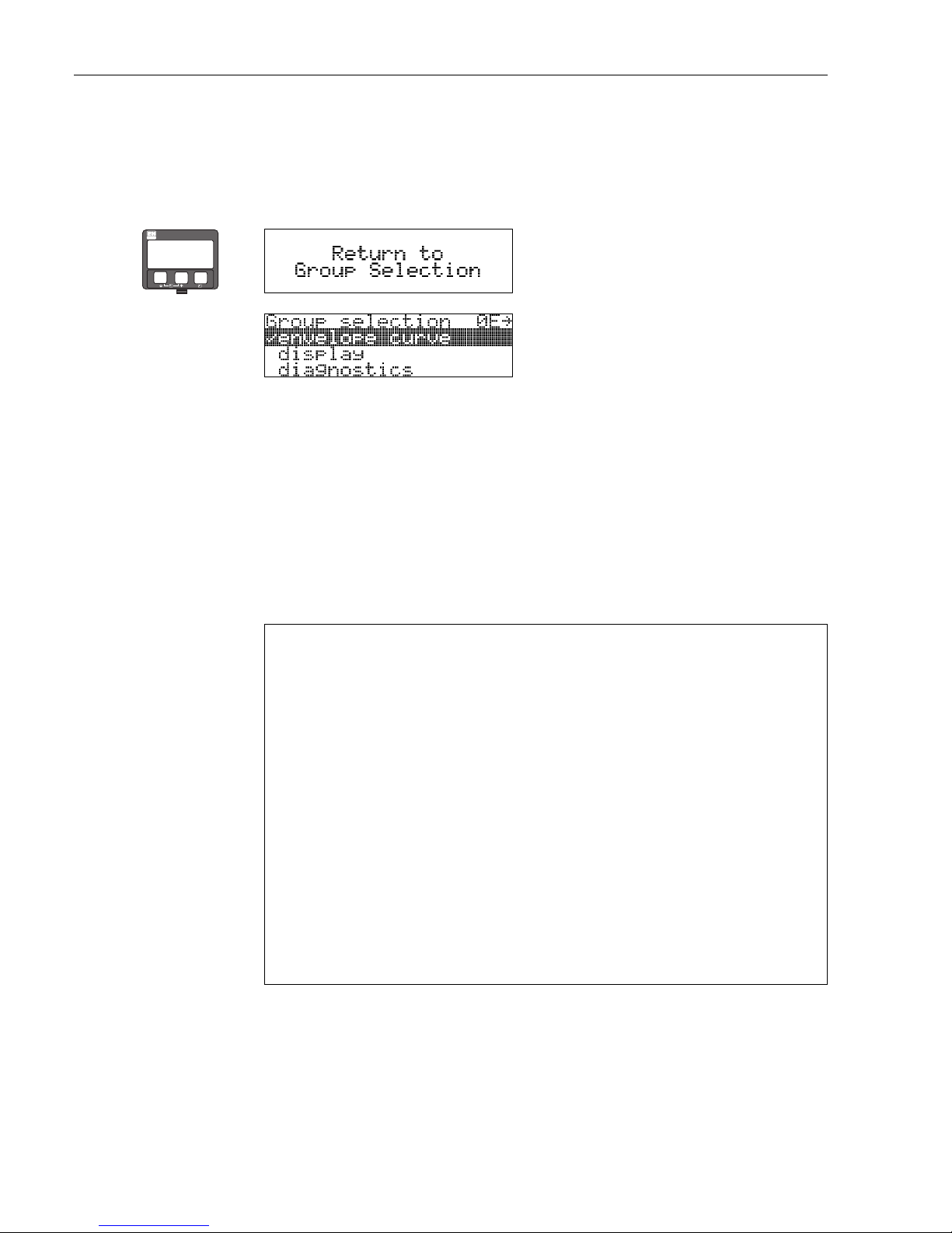
Commissioning Levelflex M FMP41C with HART/4...20 mA
54 Endress + Hauser
Exiting the navigation
•Press
F
again to run through the different modes of the envelope curve navigation.
•Press
O
and S to exit the navigation. The set increases and shifts are retained. Only when you
reactivate the "recording curve"(0E2) function does the Levelflex use the standard display
again.
6.8 Basic Setup with the ToF Tool
To carry out the basic setup with the ToF Tool operating program, proceed as follows:
• Start the ToF Tool operating program and establish a connection
• Select the "basic setup" function group in the navigation bar
The following display appears on the screen:
Basic Setup step 1/6:
• Status image
• Enter the measuring point description (TAG number).
L00-FMP4xxxx-20-00- 00-en-001
!
Note!
• Each parameter that is changed must be confirmed with the RETURN key!
•The "Next" button moves you to the next screen display:
⇒
⇓
After 3 s, the following message appears
ENDRESS + HAUSER
E
+
–
Page 55

Levelflex M FMP41C with HART/4...20 mA Commissioning
Endress + Hauser 55
Basic Setup step 2/6:
• Enter the application parameters:
– tank properties (for a description, → ä 41)
– medium properties (for a description, → ä 42)
– process properties (for a description, → ä 43)
l00-fmp4xxxx-20-0 0-00-en-002
Basic Setup step 3/6:
• Enter the application parameters:
– end of probe (for a description, → ä 43)
l00-fmp4xxxx-20-0 0-00-en-003
Page 56

Commissioning Levelflex M FMP41C with HART/4...20 mA
56 Endress + Hauser
Basic Setup step 4/6:
• Enter the application parameters:
– probe length (for a description, → ä 44)
– probe (for a description, → ä 44)
– probe length (for a description, → ä 44)
– determine length (for a description, → ä 44)
l00-fmp4xxxx-20-00-0 0-en-004
Basic Setup step 5/6:
• Enter the application parameters:
– empty calibration (for a description, → ä 45)
– full calibration (for a description, → ä 45)
l00-fmp4xxxx-20-00-0 0-en-005
Page 57

Levelflex M FMP41C with HART/4...20 mA Commissioning
Endress + Hauser 57
Basic Setup step 6/6:
• This step starts the tank mapping
• The measured distance and the current measured value are always displayed in the header
• for a description, → ä 48)
l00-fmp4xxxx-20-0 0-00-en-004
6.8.1 Blocking distance
!
Note!
Please reenter the blocking distance in the function "upper block.dist" (059) when installing the
device in a high nozzle: upper blocking distance (UB) = nozzle height (H) + 50 mm.
L00-FMP4xxxx-14-00- 06-xx-001
UB
H
50
Page 58

Commissioning Levelflex M FMP41C with HART/4...20 mA
58 Endress + Hauser
6.8.2 Envelope curve with the ToF Tool
After the basic setup, an evaluation of the measurement using the envelope curve is
recommended (→ ä 58).
L00-FMP4xxxx-20-00- 00-en-007
!
Note!
For the optimization of the measurement the installation of the Levelflex in another place can be
executed when enterference echoes.
An evaluation of the measurement with the aid of the envelope curve
Typical curve shape:
The following examples display typical curve shapes for a rope or rod probe in an empty tank. For
all probe types, a negative probe end signal is shown. For rope probes, the end weight causes an
additional preliminary positive echo (see rope probe diagram).
L00-FMP40xxx-05-00-0 0-en-024
Level echoes are detected as positive signals in the envelope curve. Interference echoes can be both
positive (e.g. reflections from internals) and negative (e.g. nozzles). The envelope curve, the map
and the differential curve are used for the evaluation.Level echoes are searched for in the differential
curve.
400.00
400.00
[mV]
[mV]
300.00
300.00
200.00
200.00
100.00
100.00
0.00
0.00
-100.00
-100.00
-200.00
-200.00
-300.00
-300.00
-400.00
-400.00
-500.00
-500.00
0.00
0.00
0.20
0.20
0.40
0.40
0.60
0.60
0.80
0.80
1.00
1.00 1.20 1.40
[m]
[m]
LNLNE
E
F
F
(1.00 m, -143.00 mV)
(1.08 m, -115.00mV)
Rod probe
Rope probe
Probe end signal
Launch pulse
Probe end signal
Launch pulse
Page 59

Levelflex M FMP41C with HART/4...20 mA Commissioning
Endress + Hauser 59
Evaluation of the measurement:
• The map must correspond to the course of the envelope curve (for rod probes up to approx. 5 cm
and for rope probes up to approx. 25 cm before the end of the probe) when the tank is empty.
• Amplitudes in the differential curve should be at a level of 0 mV when the tank is empty and lie
within the span that is specified by the probe-specific blocking distances. In order to not detect
any interference echoes, there must be no signals that exceed the echo threshold when the tank
is empty.
• For partially-filled tanks, the map may only differ from the envelope curve at the position of the
level echo. The level signal is then detected unequivocally as a positive signal in the differential
curve. For detecting the level echo, the amplitude must lie above the echo threshold.
L00-FMP40xxx-05-0 0-00-en-025
6.8.3 User-specific applications (operation)
For details of setting the parameters of user-specific applications, see separate documentation
BA245F – "Description of the instrument functions" on the enclosed CD-ROM.
400.00
400.00
400.00
[mV]
[mV]
[mV]
300.00
300.00
300.00
200.00
200.00
200.00
100.00
100.00
100.00
0.00
0.00
0.00
-100.00
-100.00
-100.00
-200.00
-200.00
-200.00
-300.00
-300.00
-300.00
-400.00
-400.00
-400.00
-500.00
-500.00
-500.00
0.00
0.00
0.000.20
0.20
0.200.40
0.40
0.400.60
0.60
0.600.80
0.80
0.801.00
1.00
1.00[m]
[m]
[m]
LN
LN
LNE
E
EF
F
F
(1.00 m, -143.00 mV)
(0.98 m, 0.00 mV)
(0.99 m, -137.94 mV)
Launch pulse
Negative
probe end signal
Envelope curve
Differential curve = Envelope curve Mapping
Mapping
Page 60

Maintenance Levelflex M FMP41C with HART/4...20 mA
60 Endress + Hauser
7 Maintenance
The Levelflex M measuring instrument requires no special maintenance.
Exterior cleaning
When cleaning the Levelflex M , always use cleaning agents that do not attack the surface of the
housing and the seals.
Repairs
The Endress+Hauser repair concept assumes that the measuring devices have a modular design and
that customers are able to undertake repairs themselves. Spare parts are contained in suitable kits.
They contain the related replacement instructions. All the spare parts kits which you can order from
Endress+Hauser for repairs to the Levelflex M are listed with their order numbers on → ä 70 and
73. Please contact Endress+Hauser Service for further information on service and spare parts.
Repairs to Ex-approved devices
When carrying out repairs to Ex-approved devices, please note the following:
• Repairs to Ex-approved devices may only be carried out by trained personnel or by
Endress+Hauser Service.
• Comply with the prevailing standards, national Ex-area regulations, safety instructions (XA) and
certificates.
• Only use original spare parts from Endress+Hauser.
• When ordering a spare part, please note the device designation on the nameplate. Only replace
parts with identical parts.
• Carry out repairs according to the instructions. On completion of repairs, carry our the specified
routine test on the device.
• Only Endress+Hauser Service may convert a certified device into a different certified variant.
• Document all repair work and conversions.
Replacement
After a complete Levelflex M or electronic module has been replaced, the parameters can be
downloaded into the instrument again via the communication interface. Prerequisite to this is that
the data were uploaded to the PC beforehand using the ToF Tool.
Measurement can continue without having to carry out a new setup.
• You may have to activate linearisation (see BA245F – "Description of the instrument functions"
on the enclosed CD-ROM.)
• You may need to record the tank map again (see Basic Setup)
After an probe or electronic has been replaced, a new calibration must be carried out. This is
described in the repair instructions.
Page 61

Levelflex M FMP41C with HART/4...20 mA Accessories
Endress + Hauser 61
8 Accessories
Various accessories, which can be ordered separately from Endress+Hauser, are available for the
Levelflex M.
Weather protection cover
A Weather protection cover made of stainless steel is recommended for outdoor mounting (order
code: 543199-0001). The shipment includes the protective cover and tension clamp.
L00-FMR2xxxx-00-00-06 -en-001
Welding boss for adapter 43 mm
Dimensions of the welding ring Order .
L00-FMP4xxxx-00-00- 06-en-006
Diameter D Height H
85 12 52006262
65 8 214880-0002
Material: 1.4435/SS316L
E
N
D
R
E
S
S
+H
A
U
S
E
R
M
IC
R
O
PIL
O
T II
ENDRESS+HAUSER
MICROPILOT II
IP
65
IP 65
O
r
d
e
r
C
o
d
e
:
S
e
r
.
N
o
.
:
Order Code:
Ser.-No.:
M
e
s
s
b
e
r
e
i
c
h
M
e
a
s
u
r
i
n
g
r
a
n
g
e
Messbereich
Measuring range
U
1
6
.
.
.
3
6
V
D
C
4
.
.
.
2
0
m
A
U 16...36V DC
4...20 mA
m
a
x
.
2
0
m
max.20 m
Made in Germany Maulburg
Made in Germany Maulburg
T>
7
0
°
C
:
A
t
>
8
5
°
C
T>70°C :
A
t >85°C
F12 / F23 / T12 housing
30°
H
Ø D
52
torque
5...10 Nm
Page 62

Accessories Levelflex M FMP41C with HART/4...20 mA
62 Endress + Hauser
Commubox FXA191 HART
For intrinsically safe communication with ToF Tool/FieldCare via the RS232C interface. For details
refer to TI237F/00/en.
Commubox FXA195 HART
For intrinsically safe communication with ToF Tool/FieldCare via the USB interface. For details
refer to TI404F/00/en.
Commubox FXA291
The Commubox FXA291 connects Endress+Hauser field instruments with CDI interface (=
Endress+Hauser Common Data Interface) to the USB interface of a personal computer or a
notebook. For details refer to TI405C/07/en.
!
Note!
For the following Endress+Hauser instruments you need the "ToF Adapter FXA291" as an additional
accessory:
• Cerabar S PMC71, PMP7x
• Deltabar S PMD7x, FMD7x
• Deltapilot S FMB70
• Gammapilot M FMG60
• Levelflex M FMP4x
• Micropilot FMR130/FMR131
• Micropilot M FMR2xx
• Micropilot S FMR53x, FMR540
• Prosonic FMU860/861/862
•Prosonic M FMU4x
• Tank Side Monitor NRF590 (with additional adapter cable)
ToF Adapter FXA291
The ToF Adapter FXA291 connects the Commubox FXA291 via the USB interface of a personal
computer or a notebook to the following Endress+Hauser instruments:
• Cerabar S PMC71, PMP7x
• Deltabar S PMD7x, FMD7x
• Deltapilot S FMB70
• Gammapilot M FMG60
• Levelflex M FMP4x
• Micropilot FMR130/FMR131
• Micropilot M FMR2xx
• Micropilot S FMR53x, FMR540
• Prosonic FMU860/861/862
•Prosonic M FMU4x
• Tank Side Monitor NRF590 (with additional adapter cable)
For details refer to KA271F/00/a2.
Page 63

Levelflex M FMP41C with HART/4...20 mA Accessories
Endress + Hauser 63
Remote display FHX40
L00-FMxxxxxx-00-00-06-en-003
Technical data (cable and housing) and product structure:
For connection of the remote display FHX40 use the cable which fits the communication version of
the respective instrument.
ENDRESS+HAUSER
IP 65
O
rd
e
r
C
o
d
e
:
S
e
r
.-N
o
.
:
Order Code:
Ser.-No.:
M
e
s
s
b
e
r
e
ic
h
M
e
a
s
u
r
in
g
r
a
n
g
e
Messbereich
Measuring range
U
1
6
..
.3
6
V
D
C
4
..
.
2
0
m
A
U 16...36V DC
4...20 mA
m
a
x
.
2
0
m
max.20 m
Made in Germany Maulburg
Made in Germany Maulburg
T>
7
0
°
C
:
A
t >
8
5
°C
T >70°C :
A
t >85°C
82
6,3
106
122
120
max. 80
min. 30
96
88
160
8,5
118
180
Micropilot M
Levelflex M
Prosonic M
Separate housing
FHX 40 (IP 65)
Cable
122
150
80
Wall-mounting
(without mounting bracket)
Pipe-mounting
(mounting bracket and plate
supplied optionally,
s. product structure)
pipe
Max. cable length 20 m (65 ft)
Temperature range -30 °C...+70 °C (-22 °F...158 °F)
Degree of protection IP65 acc. to EN 60529 (NEMA 4)
Materials Housing: AlSi12; cable glands: nickle plated brass
Dimensions [mm] / [inch] 122x150x80 (HxWxD) / 4.8x5.9x3.2
Approval:
ANn-hazardous area
1 ATEX II 2 G EEx ia IIC T6, ATEX II 3D
S FM IS Cl.I Div.1 Gr.A-D
U CSA IS Cl.I Div.1 Gr.A-D
N CSA General Purpose
K TIIS ia IIC T6 (in preparation)
Cable:
1 20m/65ft; for HART
5 20m/65ft; for PROFIBUS PA/FOUNDATION Fieldbus
Additional option:
A Basic version
B Mounting bracket, pipe 1"/ 2"
FHX40 - Complete product designation
Page 64

Accessories Levelflex M FMP41C with HART/4...20 mA
64 Endress + Hauser
Isolated tie down
Mounting-kit Order - No.
L00-FMP4xxxx-17-00- 00-en-036
for 4mm rope probe 52014249
for 6mm rope probe 52014250
If a rope probe has to be fixed and asecure grounded
mounting is not possible, we recommend using the insulating
sleeve made of PEEK-GF30 with accompanying DIN 580
eye-bolt made of stainless steel.
Max. process temp.150 °C.
Due to the risk of electrostatic charge, theinsulating sleeve is
not suitable for use inhazardous areas.In these cases the
fixing must be reliably grounded (→ ä 19).
D
Insulating
sleeve
Reliable, isolated mounting
eye-bolt
D = 20 mm at
M8 DIN 580 for 4 mm rope
D = 25 mm at
M10 DIN 580 for 6 mm rope
Page 65

Levelflex M FMP41C with HART/4...20 mA Trouble-shooting
Endress + Hauser 65
9 Trouble-shooting
9.1 Trouble-shooting instructions
L00-FMP4xxxx-19-00- 00-en-010
Instrument does
not respond
Check voltage and
compare it with the
specifications on the
nameplate.
Connect the
correct voltage
Instrument works? Ready
Check the polarity
of the voltage.
Check power connection
to electronic board
Correct the polarity
Connect plug
Instrument works?
Instrument works?
Ready
Ready
Values on display
invissible
ok
ok
ok
Yes
Yes
Yes
No
No
No
No
Not ok
Not ok
Not ok
Check plug contact
of the display.
Connect the plug
correctly
Correct configuration
Display works?
Ready
Ready
Yes
ok
No
Not ok
Yes
No
Levelflex M -Trouble Shooting
ok
Output current between
3.6 …22mA ?
Contrast:
FO+
The display is possibly defective.
Contact Endress+Hauser Service
Yes
Output current
<3.6mA?(2wire)
<2.4mA?(4wire)
No
Check cabling
Correct the
cabling
Current is ok? Ready
Yes
No
Possibly defective electronics
Contact Endress+Hauser Service
HART
communication
does not
function
Is the communication
resistor installed
according to the
OM?
Install the fuse
(see the OM)
Communication ok?
Ready
Ready
ok
Yes
Yes
No
No
Connect the
Commubox
(see the OM)
Communication ok?
Ready
Set the switch
correctly
Communication ok
Ready
Ready
Contact ServiceEndress+Hauser
Contact ServiceEndress+Hauser
Contact Endress+Hauser Service
ok
ok
ok
Yes
No
Yes
Yes
No
No
ok
Not ok
Not ok
Not ok
Not ok
Not ok
Not ok
?
Is the switch on the
Commubox for
selecting HART
in the correct position?
Is the Commubox
connected according
to the OM?
Communication
via Service adapter
does not function
Instrument
measures
incorrectly
Check configuration
of COM port on PC
Check basic setup
Proceed according
to section
'Trouble shooting’ in OM
Repeat
basic setup
Not ok
Yes
Yes
Yes
Yes
Yes
Communication
PAdoes not
function
Check cabling +
terminator
EMC interference?
ok
Correct cabling +
terminator
Not ok
Check screening
(see BA Section
'Connection’)
Yes
Communication ok?
Communication ok?
Measurement ok?
Ready
Yes
No
Communication ok?
Ready
Yes
No
Page 66

Trouble-shooting Levelflex M FMP41C with HART/4...20 mA
66 Endress + Hauser
9.2 System error messages
Code Description Possible cause Remedy
A102 checksum error
general reset & new calibr.
required
device has been powered off before data
could be stored;
emc problem;
E
2
PROM defect
reset
avoid emc problem;
if alarm prevails after reset,
exchange electronics
W103 initialising - please wait E
2
PROM storage not yet finished wait some seconds; if warning
prevails, exchange electronics
A106 downloading please wait processing data download wait until warning disappears
A110 checksum error
general reset & new calibr.
required.
device has been powered off before data
could be stored;
emc problem;
E
2
PROM defect
reset
avoid emc problem;
if alarm prevails after reset,
exchange electronics
A111 electronics defect RAM defective reset
if alarm prevails after reset,
exchange electronics
A113 electronics defect ROM defective reset
if alarm prevails after reset,
exchange electronics
A114 electronics defect E
2
PROM defective reset
if alarm prevails after reset,
exchange electronics
A115 electronics defect general hardware problem Reset
if alarm prevails after reset,
exchange electronics
A116 download error
repeat download
checksum of stored data not correct restart download of data
A121 electronics defect no factory calibration existant; E
2
PROM
defective
contact service
W153 initialising - please wait initialisation of electronics wait some seconds; if warning
prevails, power off device and
power on again
A160 checksum error
general reset & new calibr.
required.
device has been powered off before data
could be stored;
emc problem;
E
2
PROM defect
reset
avoid emc problem;
if alarm prevails after reset,
exchange electronics
A164 electronics defect hardware problem reset
if alarm prevails after reset,
exchange electronics
A171 electronics defect hardware problem reset
if alarm prevails after reset,
exchange electronics
A221 Probe pulse deviation from
average values
HF module or cable between HF module
and electronics defective
Check contacts on HF module
If fault cannot be eliminated:
Replace HF module
A241 Broken probe Broken probe orvalue for probe length is
too short
Check the probe length in 033,
Check the probe itself,if the probe is
broken, change the probe, or
change to a non contact system
A251 Feedthrough Lost contact in the process feedthrough Replace process feedtrough
A261 HF cable defective HF cable defective or HF connector
removed
Check HF connector, replace cable
if defective
W275 Offset too high Temperature at the electronics too high or
HF module defective
Check temperature, replace HF
module if defective
W512 recording of mapping please
wait
mapping active wait some seconds until alarm
disappears
Page 67

Levelflex M FMP41C with HART/4...20 mA Trouble-shooting
Endress + Hauser 67
W601 linearisation ch1 curve not
monotone
linearization not monotonously increasing correct linearisation table
W611 less than 2 linearisation
points for channel 1
number of entered linearization points < 2 correct linearisation table
W621 simulation ch. 1 on simulation mode is active switch off simulation mode
E641 no usable echo
channel 1
check calibr.
echo lost due to application conditions of
built up on antenna
check installation;
clean probe (cf. Operating
Instructions)
W650 Signal/noise ratio too low
or no echo
noise on signal to high eliminate electromagnetic
interference
E651 level in safety distance - risk
of overspill
level in safety distance alarm will disappear as soon as level
leaves safety distance
A671 linearisation ch1 not
complete, not usable
linearisation table is in edit mode activate linearisation table
W681 current ch1 out of range current out of range
(3.8 mA ... 21,5 mA)
check calibration and linearisation
Code Description Possible cause Remedy
Page 68

Trouble-shooting Levelflex M FMP41C with HART/4...20 mA
68 Endress + Hauser
9.3 Application errors
Error Output Possible cause Remedy
A warning or alarm
has occurred.
Depending on the configuration See table of
error messages
(→ ä 66)
1. See table of error messages
(→ ä 66)
Measured value
(00) is incorrect
L00-FMP4xxxx-19-00- 00-en-019
Measured distance
(008) OK?
yes →1. Check empty calibr. (005) and
full calibr. (006)
2. Check linearisation:
→
level/ullage (040)
→
max. scale (046)
→
diameter vessel (047)
→
Check table
no
↓
An interference echo
may have been
evaluated.
yes →1. Carry out tank mapping
→
basic setup
No change off
measured value on
filling/emptying
L00-FMR2xxxx-19-00-00 -en-014
Interference echo from
installations, nozzle
or extension on the
probe
1. Carry out tank mapping
→
basic setup
2. If necessary, clean probe
3. If necessary, select better
mounting position
E 641 (loss of
echo) after turn on
the power supply
If the instrument is configured to Hold by loss of
echo the output is set to any value/current.
noise level during the
initialisation phase to
high.
Repeat once more empty calibr.
(005).
Caution!
Before conformation change with
O
or
S
to the edit mode.
20 mA/100%
F m/ft
E m/ft
4 mA/0% t
→
D m/ft (008)
actual
expected
20 mA/100%
4 mA/0% t
→
actual
expected
Page 69

Levelflex M FMP41C with HART/4...20 mA Trouble-shooting
Endress + Hauser 69
Device displays a
level when the
tank is empty.
L00-FMP4xxxx-19-00- 00-en-020
Incorrect probe length 1. Carry out automatic probe length
detection when the tank is
empty.
2. Carry out mapping over entire
probe when the tank is empty
(probe free!).
Measured value
incorrect (slope
error in the entire
measuring range)
L00-FMP4xxxx-19-00- 00-en-021
Tank properties
incorrect.
LN < 4 m and "Aluminium tank" tank
properties selected
→
Calibration not possible.
→
Selection
→
Select standard
→
Thresholds too high
Medium properties
incorrect.
Select lower medium properties.
20 mA/100%
4 mA/0% t →
actual
expected
20 mA/100%
4 mA/0% t →
2.) actual
1.) actual
expected
Page 70

Trouble-shooting Levelflex M FMP41C with HART/4...20 mA
70 Endress + Hauser
9.4 Spare parts
!
Note!
You can order spare parts directly from your Endress+Hauser service organization by giving the
serial number which is printed on the measuring transducer nameplate (→ ä 8). The
corresponding spare part number also appears on each spare part. Installation instructions are given
on the instruction card that is also delivered.
Spare parts Levelflex M FMP41C housing type F12 with a combined connection
compartment and electronics compartment
L00-FMP41Cxx-00-00-0 6-xx-001
See the following pages for probe versions and spare parts for probes.
ENDRESS+HAUSER
M
ICR
OPILOT II
IP 65
O
rd
e
r C
o
d
e
:
S
e
r
.-N
o
.:
M
e
s
s
b
e
re
ic
h
M
e
a
s
u
r
in
g
r
a
n
g
e
U
1
6
...3
6
V
D
C
4
...2
0
m
A
m
a
x
.
2
0
m
Made in Germany Maulburg
T>
7
0
°C
:
A
t
>
8
5
°
C
1
2
3
4
Terminal
ENDRESS+HAUSER
A
c
h
t
u
n
g
b
e
i
A
b
z
ie
h
e
n
d
e
s
K
o
a
x
-
S
t
e
c
ke
r
s
(
z
.
B
.H
F
-
M
o
d
u
l
We
c
h
s
e
l)
im
E
x
-
B
e
r
e
ic
h
:
E
s
is
t
s
ic
h
e
r
z
u
s
t
e
lle
n
,
d
a
s
s
b
e
i
a
b
g
e
z
o
g
e
n
-
e
m
K
o
a
x
-
S
t
e
c
ke
r
k
e
in
e
e
le
k
t
r
o
s
t
a
t
is
c
h
e
Au
f
la
d
u
n
g
(
is
o
lie
r
t
e
K
a
p
a
z
it
ä
t)
d
e
r
S
o
n
d
e
e
r
f
o
lg
t
(
z
.
B
.d
u
r
c
h
B
e
f
ü
lle
n
o
d
e
r
E
n
t
le
e
r
e
n
)
.
B
e
i
R
e
p
a
r
a
tu
r
e
n
K
o
a
x
-
S
t
e
c
ke
r
s
o
f
o
r
t
w
i
e
d
e
r
a
u
f
s
t
e
c
ke
n
!
A
c
h
tu
n
g
b
e
i
A
b
z
ie
h
e
n
d
e
s
K
o
a
x
-
S
t
e
c
ke
r
s
(
z
.
B
.H
F
-
M
o
d
u
l
We
c
h
s
e
l)
im
E
x
-
B
e
r
e
ic
h
:
E
s
i
s
t
s
ic
h
e
r
z
u
s
t
e
lle
n
,
d
a
s
s
b
e
i
a
b
g
e
z
o
g
e
n
-
e
m
K
o
a
x
-
S
t
e
c
ke
r
k
e
in
e
e
le
k
t
r
o
s
t
a
t
is
c
h
e
Au
f
la
d
u
n
g
(
is
o
l
ie
r
t
e
K
a
p
a
z
it
ä
t)
d
e
r
S
o
n
d
e
e
r
f
o
lg
t
(
z
.
B
.d
u
r
c
h
B
e
f
ü
lle
n
o
d
e
r
E
n
t
le
e
r
e
n
)
.
B
e
i
R
e
p
a
r
a
tu
r
e
n
K
o
a
x
-
S
t
e
c
ke
r
s
o
f
o
r
t
w
ie
d
e
r
a
u
f
s
te
c
ke
n
!
35
12
12
10
11
30
40
31
20
Page 71

Levelflex M FMP41C with HART/4...20 mA Trouble-shooting
Endress + Hauser 71
10 Housing
52013409 Housing F12, aluminium, coated, M20, metal
52013348 Housing F12, aluminium, coated, G1/2, 4-wire
52013349 Housing F12, aluminium, coated, NPT1/2, 4-wire
52013350 Housing F12, aluminium, coated, M20, 4-wire
52013351 Housing F12, aluminium, coated, M20, metal
543120-0022 Housing F12, aluminium, G1/2
543120-0023 Housing F12, aluminium, NPT1/2
543120-0024 Housing F12, aluminium, M20
11 Hood for terminal compartment
52006026 Cover for the connection compartment F12
52019062 Cover for the connection compartment F12, FHX40
12 Set of screws
535720-9020 Set of screws for housing F12/T12
20 Cover
52005936 Cover F12/T12 aluminium, inspection glass, seal
517391-0011 Cover F12/T12 aluminium, coated, seal
30 Electronics
71025474 Elektronics FMP4x, Ex, 2 wire, HART,V4.0
71025475 Elektronics FMP4x, Ex, 4 wire, HART,V4.0
31 HF module
52019780 HF module LEVELFLEX-M
35 Terminal module / power unit
52006197 Terminal module 4-pin, HART, 2-wire with connecting cable
52013304 Power unit, 10.5...32V DC (housing F12) for electronics, 4-wire
52013305 Power unit, 90 ...250V AC (housing F12) for electronics, 4-wire
52015585 Power unit, CSA, 10.5...32V DC (housing F12) for electronics, 4-wire
52015586 Power unit, CSA, 90...250V AC (housing F12) for electronics, 4-wire
40 Display
52005585 Display/operating module VU331
Page 72

Trouble-shooting Levelflex M FMP41C with HART/4...20 mA
72 Endress + Hauser
Spare parts for Levelflex M FMP41C housing type F23
20 Cover
52018670 Cover F23 316L, sight glass, gasket
52018681 Cover F23 316L, gasket
Page 73

Levelflex M FMP41C with HART/4...20 mA Trouble-shooting
Endress + Hauser 73
Spare parts for Levelflex M FMP41C housing type T12 with separate connecting
compartment
L00-FMP41Cxx-00-00 -06-xx-002
EN
DR
ESS
+H
A
US
ER
M
IC
R
O
PILOT FM
R
IP 65
O
r
d
e
r
C
o
d
e
:
S
e
r
.-
N
o
.:
M
e
s
s
b
e
r
e
ic
h
M
e
a
s
u
r
in
g
r
a
n
g
e
U
1
6
...3
6
V
D
C
4
...2
0
m
A
m
a
x
.
2
0
m
Made in Germany Maulburg
T>
7
0
°
C
:
A
t
>
8
5
°
C
E
N
D
R
ES
S+
HA
U
S
E
R
Achtung bei Abziehen des Koax-Steckers
(z.B.HF-Modul Wechsel) im Ex-Bereich:
Es ist sicherzustellen, dass bei abgezogen-
em Koax-Stecker keine elektrostatische
Aufladung (isolierte Kapazit
ät) der Sonde
erfolgt (z.B.durch Bef
üllen oder Entleeren).
Bei Reparaturen Koax-Stecker sofort
wieder aufstecken!
25
35
12
12
10
11
30
40
31
20
Page 74

Trouble-shooting Levelflex M FMP41C with HART/4...20 mA
74 Endress + Hauser
10 Housing
52006205 Housing T12, aluminium, M20, PEL, cover
543180-1023 Housing T12, aluminium, NPT1/2, PEL
11 Hood for terminal compartment
52005643 Hood T12
12 Set of screws
535720-9020 Set of screws for housing F12/T12
20 Cover
52005936 Cover F12/T12 aluminium, inspection glass, seal
517391-0011 Cover F12/T12 aluminium, coated, seal
25 Cover for the connection compartment
518710-0020 Cover T3/T12, aluminium, coated, seal
30 Electronics
71025474 Elektronics FMP4x, Ex, 2 wire, HART,V4.0
31 HF module
52019780 HF module LEVELFLEX-M
35 Terminal module / power unit
52013302 Terminal module Ex d, 4-pin, 2-wire, HART, T12
52018949 Terminal module EEx ia, 4-pin, HART, T12, OVP
40 Display
52005585 Display/operating module VU331
Page 75

Levelflex M FMP41C with HART/4...20 mA Trouble-shooting
Endress + Hauser 75
FMP41C - probes, accessories and spare parts
In preparation.
Page 76

Trouble-shooting Levelflex M FMP41C with HART/4...20 mA
76 Endress + Hauser
9.5 Return
The following procedures must be carried out before a transmitter is sent to Endress+Hauser e.g.
for repair or calibration:
• Remove all residue which may be present. Pay special attention to the gasket grooves and crevices
where fluid may be present. This is especially important if the fluid is dangerous to health, e.g.
corrosive, poisonous, carcinogenic, radioactive, etc.
• Always enclose a duly completed "Declaration of contamination" form (a copy of the “Declaration
of contamination” is included at the end of this operating manual). Only then can Endress
+Hauser transport, examine and repair a returned device.
• Enclose special handling instructions if necessary, for example a safety data sheet as per EN 91/
155/EEC.
Additionally specify:
• An exact description of the application
• The chemical and physical characteristics of the product
• A short description of the error that occurred (specify error code if possible)
• If necessary, give the error code
9.6 Disposal
In case of disposal please seperate the different components according to their material consistence.
9.7 Software history
9.8 Contact addresses of Endress+Hauser
Contact addresses can be found on our homepage: www.endress.com/worldwide. If you have any
questions, please do not hesitate to contact your Endress+Hauser representative.
Software version / Date Software changed Documentation changes
V 01.02.02 / 08.2003 Original software.
Operated via:
– ToF Tool
– Commuwin II (as of Version 2.08-1 Update C)
– HART-Communicator DXR375 withRev. 1, DD 1.
V 01.02.04 / 07.2004 "mapping" function improved Specification of the measuring accuracy at the end of probe
V 01.02.06 / 01.2005 Function "cho lost" improved
V 01.04.00 / 03.2006 function "detection window" • Description of Instrument Functions
• Operating menu extended see Cap. 11.1
Page 77

Levelflex M FMP41C with HART/4...20 mA Technical data
Endress + Hauser 77
10 Technical data
10.1 Additional technical data
10.1.1 Input
Measured variable The measured variable is the distance between a reference point (see Fig. on → ä 14) and the
product surface.
Subject to the input empty distance (E, see Fig. on → ä 86), the level is calculated.
Alternatively, the level can be converted by means of linearisation (32 points) into other variables
(volume, mass).
10.1.2 Output
Output signal 4…20 mA with HART protocol
Signal on alarm Error information can be accessed via the following interfaces:
•Local display:
– Error symbol (→ ä 31)
– Plain text display
• Current output, signal on error can be selected (e.g. according to NAMUR recommendation NE
43).
• Digital interface
Linearization The Levelflex M linearisation function enables conversion of the measured value into any desired
length or volume units and mass or %. Linearisation tables for volume calculation in cylindrical tanks
are pre-programmed. Any other tables from up to 32 value pairs can be input manually or semiautomatically.
The creation of a linearisation table with the ToF Tool or FieldCare is particularly convenient.
10.1.3 Performance characteristics
Reference operating
conditions
• temperature = +20 °C (68 °F) ±5 °C (9 °F)
• pressure = 1013 mbar abs. (14.7 psia) ±20 mbar (0.3 psi)
• humidity = 65 % ±20%
• Reflection factor ≥ 0.8 (surface of the water for coax probe, metal plate for rod and rope probe
with min. 1 m ∅)
• Flange for rod or rope probe ≥ 30 cm ∅
• Distance to obstructions ≥ 1m
Maximum measured error Is in Function group "basic setup" (00) starting from → ä 41.
Resolution • Digital / analog in % 4…20 mA
• analog: 0.03 % of the measuring range
Reaction time The reaction time is dependent on the configuration.
Shortest time:
• 2-wire electronics: 1 s
• 4-wire electronics: 0.7 s
Page 78

Technical data Levelflex M FMP41C with HART/4...20 mA
78 Endress + Hauser
Influence of ambiente
temperature
The measurements are carried out in accordance with EN 61298-3:
• digital output:
– FMP41C
average T
K
: 0.6 mm/10 K, max. ±3.5 mm over the entire temperature range -40 °C...+80 °C
2-wire:
• Current output (additional error, in reference to the span of 16 mA):
• Zero point (4 mA)
average T
K
: 0.032 %/10 K, max. 0.35 % over the entire temperature range -40 °C...+80 °C
• Span (20 mA)
average T
K
: 0.05 %/10 K, max. 0.5 % over the entire temperature range -40 °C...+80 °C
4-wire:
• Current output (additional error, in reference to the span of 16 mA):
• Zero point (4 mA)
average T
K
: 0.02 %/10 K, max. 0.29 % over the entire temperature range -40 °C...+80 °C
• Span (20 mA)
average T
K
: 0.06 %/10 K, max. 0.89% over the entire temperature range -40 °C...+80 °C
10.1.4 Operating conditions: Environment
Ambient temperature range Ambient temperature for the transmitter: -40 °C ... +80 °C (-40 °F … +176 °F)
The functionality of the LCD display may be limited for temperatures
Ta<-20 °C and Ta>+60 °C.
A weather protection cover should be used for outdoor operation if the instrument is exposed to
direct sunlight.
Ambient temperature limits If temperatures above 80 °C are present at the process connection, the permitted ambient
temperature is reduced according to the following diagram (temperature derating):
L00-FMP41xxx-05-00-0 0-en-001
Storage temperature -40 °C … +80 °C (-40 °F … +176°F)
Climate class DIN EN 60068-2-38 (test Z/AD)
Vibration resistance DIN EN 60068-2-64 / IEC 68-2-64: 20…2000 Hz, 1 (m/s
2)2
/Hz
T
2
[°C]
T
1
[°C]
-40 0
-40
0
40
60
80
100 150
200
80
T
2
T
1
max. process connection temperature
max. ambient temperature
80 °C with separate
housing
40 °C compact:
F23 housing
55 °C
F12 housing
T12 housing
compact:
Page 79

Levelflex M FMP41C with HART/4...20 mA Technical data
Endress + Hauser 79
Cleaning the probe Depending on the application, soilings or sediments can accumulate on the probe. A thin, even layer
only influences measurement slightly. Thick layers can dampen the signal and then reduce the
measuring range. Heavy, uneven build-up, adhesion e.g. through crystallisation, can lead to
incorrect measurement. In this case, we recommend that you use a non-contact measuring
principle, or check the probe regularly for soiling
Electromagnetic
compatibility (EMC)
When installing the probes in metal and concrete tanks and when using a coax probe:
• Interference Emission to EN 61326, Electrical Equipment Class B
• Interference immunity to EN 61326, Annex A (Industrial area) and NAMUR Recommendation
NE 21 (EMC)
The measured value can be affected by strong electromagnetic fields when installing rod and rope
probes without a shielding/metallic wall, e.g. plastic, and in wooden silos.
• Interference emission to EN 61326, Class A equipment.
• Interference immunity: the measured value can be affected by strong electromagnetic fields.
10.1.5 Operating conditions: Process
Process temperature range The maximum permitted temperature at the process connection (see Figure for measuring point) is
determined by the process connection ordered:
For FMP41C with Endress+Hauser adapter 43 mm: 0 °C ... 150 °C (32 °F...302 °F).
Lateral load-bearing capacity of the rod probe: 30 Nm
Process pressure limits All models: Vacuum up to max. 40 bar (585,9psi).
For FMP41C with Endress+Hauser universal adapter: max. 6 bar (87 psi).
For FMP41C with Tri-Clamp see ordering Information.
Materials used in the process
L00-FMP4xxxx-16-00- 00-en-002
Min. temperature Max. temperature
-40° C [-40 °F] +200° C [392 °F]
measured
here
Material Approval
Rod probe, Rope probe PFA (Daikin PFA AP230) FDA, 3A
Cladding PTFE (Dyneon TFM1600) FDA, 3A
TFM 1600
TFM 1600
PFA
2mm
PFA
2mm
PFA
2mm
PFA PFAPFA PFA
1.4401 / PFA
0.75 mm
Rope probe Rod probe
Page 80

Technical data Levelflex M FMP41C with HART/4...20 mA
80 Endress + Hauser
Dielectric constant • Rod and rope probe: ε r ≥ 1.6
10.1.6 Mechanical construction
Tolerance of probe length
Weight
Material • Housing:
– housing F12/T12: aluminium (AlSi10Mg), seawater-resistant, chromated, powder-coated
– housing F23: 316L, corrosion-resistant steel
• Sight window: glass
Rod probes
over 1 m / 3.2 ft 3 m / 9.8 ft 6 m / 20 ft
up to 1 m / 3.2 ft 3 m / 9.8 ft 6 m / 20 ft
admissible tolerance (mm / inch) - 5 / - 0.2 - 10 / - 0.4 - 20 / - 0.8 - 30 / - 1.2
Rope probes
over 1 m / 3.2 ft 3 m / 9.8 ft 6 m / 20 ft
up to 1 m / 3.2 ft 3 m / 9.8 ft 6 m / 20 ft
admissible tolerance (mm / inch) - 10 / - 0.4 - 20 / - 0.8 - 30 / - 1.2 - 40 / - 1.6
Levelflex M FMP41C
+ rod probe
FMP41C
+ rope probe
Weight for the F12
or T12 housing
approx. 3.5 kg
+
approx. 1.1 kg/
metre
Probe length
+
Flange weight
approx. 3.5 kg
+
approx. 0.5 kg/m
Probe length
+
Flange weight
Weight for the F23
housing
approx. 6.8 kg
+
approx. 1.1 kg/
metre
Probe length
+
Flange weight
approx. 6.8 kg
+
approx. 0.5 kg/m
Probe length
+
Flange weight
Page 81

Levelflex M FMP41C with HART/4...20 mA Technical data
Endress + Hauser 81
10.1.7 Certificates and approvals
CE approval The measuring system meets the legal requirements of the EC-guidelines. Endress+Hauser confirms
the instrument passing the required tests by attaching the CE-mark.
Ex approval Correlation of safety instructions (XA) and certificates (ZE) to the instrument:
EHEDG approval Under development.
3A approval Under development.
Overspill protection WHG. See "Ordering structure" on → ä 8- (see ZE 256F/de).
Telecommunication Fulfils "Part 15" of the FCC regulations for an "Unintentional Radiator". All probes meet the
requirements for a "Class A Digital Device".
In addition to this, all probes in metallic tanks meet the requirements for a "Class B Digital Device".
Device Certificate Explosion protection Output1)Communication Housing 2)KEMA 04
ATEX
XA WHG
FMP41C A non-ex B, G, H HART, 4...20 mA — — — —
D PROFIBUS PA — — — —
F FOUNDATION Fieldbus — — — —
F non-ex + WHG B, G, H HART, 4...20 mA — — — ZE256F/00/de
D PROFIBUS PA — — — ZE256F/00/de
1 ATEX II 1/2 G EEx ia IIC T6 B HART, 4...20 mA A 1129X XA261F-A —
D PROFIBUS PA A 1129X XA262F-A —
F FOUNDATION Fieldbus A 1129X XA262F-A —
B HART, 4...20 mA B 1129X XA268F-A —
D PROFIBUS PA B 1129X XA269F-A —
F FOUNDATION Fieldbus B 1129X XA269F-A —
B HART, 4...20 mA D 1129X XA272F-A —
D PROFIBUS PA D 1129X XA273F-A —
F FOUNDATION Fieldbus D 1129X XA273F-A —
3 ATEX II 1/2 G EEx em [ia] IIC T6 B HART, 4...20 mA C 1129X XA264F-A —
D PROFIBUS PA C 1129X XA264F-A —
F FOUNDATION Fieldbus C 1129X XA264F-A —
6 ATEX II 1/2 G EEx ia IIC T6 +
WHG
B HART, 4...20 mA A 1129X XA261F-A ZE256F/00/de
D PROFIBUS PA A 1129X XA262F-A ZE256F/00/de
B HART, 4...20 mA B 1129X XA268F-A ZE256F/00/de
D PROFIBUS PA B 1129X XA269F-A ZE256F/00/de
B HART, 4...20 mA D 1129X XA272F-A ZE256F/00/de
D PROFIBUS PA D 1129X XA273F-A ZE256F/00/de
7 ATEX II 1/2 G EEx d [ia] IIC T6 B, D HART, 4...20 mA
PROFIBUS PA
C 1129X XA263F-A —
1) assignment, see ordering information: 40 electronic insert/communication
2) assignment, see ordering information: 70 housing
Page 82

Technical data Levelflex M FMP41C with HART/4...20 mA
82 Endress + Hauser
External standards and
guidelines
EN 60529
Protection class of housing (IP-code)
EN 61010
Safety regulations for electrical devices for measurement, control, regulation and laboratory use.
EN 61326
Emissions (equipment class B), compatibility (appendix A - industrial area)
NAMUR NE 21
Electromagnetic Compatibility (EMC) of Industrial Process and Laboratory Control Equipment.
NAMUR NE 43
Standardization of the Signal Level for the Failure Information of Digital Transmitters.
10.1.8 Supplementary Documentation
!
Note!
This supplementary documentation can be found on our product pages on www.endress.com.
• Technical Information (TI386F/00/en)
• Safety Manual "Handbook of functional safety" (SD174F/00/en)
• Certificate "Allgemeine bauaufsichtliche Zulassung" (ZE256F/00/de)
Page 83

Levelflex M FMP41C with HART/4...20 mA Technical data
Endress + Hauser 83
Page 84

Appendix Levelflex M FMP41C with HART/4...20 mA
84 Endress + Hauser
11 Appendix
11.1 Operating menu HART (Display modul), ToF Tool
L00-FMP4xxxx-19-00- 01-en-002
safety settings
basic setup
output on alarm
MIN -10% 3.6mA
hold
MAX 110% 22mA
standard
aluminium tank
plastic tank
bypass / pipe
coax probe
concrete wall
unknown
DC: 1.4 … 1.6
DC: 1.6 … 1.9
DC: 1.9 … 2.5
DC: 2.5 … 4
DC: 4 … 7
DC: > 7
standard
fast change
slow change
test: no filter
user specific
tank properties
end of probe
free
tie down isolated
tie down gnd.
output on alarm
enter value enter value
medium cond.
outp. echo loss
alarm
hold
ramp %MB/min
process proper.
ramp %span/min
empty calibr.
enter value
delay time
in case of echo loss
max. 4000 sec.
default: 30 s
length adjustment
01
00
010
002
030
011
003
012
004
013
005
014
03
probe length
not modified
modified
probe
free
probe length
probe length
determine length
length OK
031
032 033
033
034
level/ullage.
level DU
ullage DU
level CU
ullage CU
Selection
mapping
common
delete map.
envelope curve
substracted signal
mapping
single curve
cyclic
commun.address
plot settings
present error
tag no.
4 mA value 20 mA value
fixed cur. value
linearisation
manual
semi-automatic
table on
horizontal cyl
linear
clear table
dist./meas.value
D and L is displayed
no. of preambels
recording curve
language
previous error
customer unit
table no.
input level
input volume
customer unit
customer unit
check distance
distance = ok
dist. unknown
dist. too big
low output limit
off
on
back to home
enter time
Default: 900 s
English
Deutsch
Francais
Espanol
Italiano
Nederlands
Katakana (japanese)
clear last error
protocol + sw-no.
linearisation
range of mapping
pres. Map dist.
input of mapping
range
is displayed
curr. output mode
reset
for reset code
see manual
next point
no
yes
start mapping
delete map.
off
on
no
yes
no.of decimals
x
x.x
x.xx
x.xxx
unlock parameter
for enter code
see manual
serial no.
linearisation
extended calibr.
output
envelope curve
display
diagnostics
system parameter
040
050
060
0E1
0A0
0C0
041
008
061
0E2
092
0A1
042
043
043
044
045
042
042
051
062
093
0A2
0C2
052
054
063
0A3
045
053
055
064
095
0A4
0C4
04
05
06
0E
09
0A
0C
standard
fixed current
current turn down
format display
decimal
094
1/16”
manual
probe free
dist. too small
covered
see Function group “leghth adjustment 03”
end of probe 030
determine length 034
too short
too long
068 069
Page 85

Levelflex M FMP41C with HART/4...20 mA Appendix
Endress + Hauser 85
L00-FMP4xxxx-19-00- 02-en-002
safety distance
from blocking distance
default: 0.1m
dist./meas.value
D and L
are displayed
in safety dist.
alarm
self holding
warning
check distance
distance = ok
dist. too small
probe free
manual
dist. unknown
dist. too big
ackn. alarm overspill protection
no
yes
standard
german WHG
range of mapping
input of
mapping range
Return to Group Selection
start mapping
full calibr.
enter value
dist./meas.value
brocken probe det
D and L
are displayed
015
008
016
051
017 018
052 053
006
008
019
dist./meas.value
D und L is displayed
simulation
sim. off
sim. level
sim. volume
sim. current
sep. character
. point
, comma
measured dist.
distance unit
max. scale
max. scale
echo quality
is displayed
simulation value
display test
off
on
off
on
off
on
measured level
download mode
diameter vessel
offset
will be added to the
measured level
output current
output damping
application par.
not modified
modified
upper block.dist
008
065
096
0A5
0C5
046
046
056
066
097
0A6
0C8
047
057
067
058
0A8
059
detection window
off
on
reset
0A7
Page 86

Appendix Levelflex M FMP41C with HART/4...20 mA
86 Endress + Hauser
11.2 Description of functions
!
Note!
A detailed description of the function groups, functions and parameters is given in the
documentation BA245F – "Description of the instrument functions" on the enclosed CD-ROM.
11.3 Function and system design
11.3.1 Measuring principle
The Levelflex is a "downward-looking" measuring system that functions according to the ToF
method (ToF = Time of Flight). The distance from the reference point (process connection of the
measuring device → ä 13) to the product surface is measured. High-frequency pulses are injected
to a probe and led along the probe. The pulses are reflected by the product surface, received by the
electronic evaluation unit and converted into level information.
This method is also known as TDR (Time Domain Reflectometry).
L00-FMP41Cxx-15-00-0 0-en-001
Input
The reflected pulses are transmitted from the probe to the electronics. There, a microprocessor
analyses the signals and identifies the level echo, which was generated by the reflection of the highfrequency pulses at the product surface. This clear signal finding benefits from the more than 30
years of experience with pulse time-of-flight procedures that have been integrated into the
development of the PulseMaster
®
Software.
The distance D to the product surface is proportional to the time of flight t of the impulse:
D = c · t/2,
with c being the speed of light.
Based on the known empty distance E, the level L is calculated:
L = E – D
Reference point for "E" see above diagram, Details → ä 39.
The Levelflex possesses functions for the interference echo suppression that can be activated by the
user. They guarantee that interference echoes from e.g. internals and struts are not interpreted as
level echoes.
20 mA
100%
4mA
0%
D
L
F
E
flange:
referencepoint of
measurement
probe length LN
Page 87

Levelflex M FMP41C with HART/4...20 mA Appendix
Endress + Hauser 87
11.3.2 Equipment architecture
Stand-alone
• Power supply directly from power line (4-wire) or from transmitter power supply unit (2-wire).
• Operation by on-site display or remote operation via HART protocol.
L00-FMxxxxxx-14-00-06-en-008
If the HART communication resistor is not installed in the supply device and HART protocol
communication is to be carried out, it is necessary to insert a ≥ 250 Ω communication resistor into
the 2-wire line.
On-site operation:
• with display and operating module VU331,
• with a Personal Computer, FXA193 (RS232C) or FXA291 and ToF Adapter FXA291 (USB) and
the operating software "ToF Tool - FieldTool Package" respectively "FieldCare".
The ToF Tool is a graphical operating software for instruments from Endress+Hauser that operate
based on the time-of-flight principle (radar, ultrasonic, guided micro-impulse). It assists with
commissioning, securing data, signal analysis and documentation of the measuring point.
11.3.3 Patents
This product may be protected by at least one of the following patents.
Further patents are pending.
• US 5,661,251 i EP 0 780 664
• US 5,827,985 i EP 0 780 664
• US 5,884,231 i EP 0 780 665
• US 5,973,637 i EP 0 928 974
ENDRESS + HAUSER
E
+–
%
ENDRESS + HAUSER
RMA 422
1
# % &
Copy
G H I
P Q R S
, ( )‘
A B C
Paste
Page
On
Page
Up
DeleteBksp
Insert
J K L
T UV
_ < >
D E F
Hot Key
+ Hot Key
M N O
W XY Z
+ * /
4
7
.
2
5
8
0
375
FIELD COMMUNICATOR
3
6
9
-
9
6
DELTABAR:* * * * * * * *
ONLINE
1 QUICK SETUP
2 OPERATING MENU
4 SV 0 °C
3 PV 352 mbar
HELP SAVE
dsdmdm
df das.
asdas fa
asas la.
- ToF Tool FieldTool
Package
- FieldCare
- ToF Tool FieldTool
Package
HART handheld
DXR375
FXA191/195
or
DXR375
transmitter power
supply unit
RMA422
or RN221N
(communication resistor
included)
PLC
Commubox
FXA191/195
operating and
display module
VU331
service adapter
FXA193
Power supply
(for 4-wire)
Page 88

Appendix Levelflex M FMP41C with HART/4...20 mA
88 Endress + Hauser
Page 89

Levelflex M FMP41C with HART/4...20 mA Index
Endress + Hauser 89
Index
A
Accessories . . . . . . . . . . . . . . . . . . . . . . . . . . . . . . . . . . . . 61
Alarm . . . . . . . . . . . . . . . . . . . . . . . . . . . . . . . . . . . . . . . . 35
Application errors . . . . . . . . . . . . . . . . . . . . . . . . . . . . . . . 68
B
Basic Setup . . . . . . . . . . . . . . . . . . . . . . . . . . . . . . 39, 41, 54
Blocking distance . . . . . . . . . . . . . . . . . . . . . . . . . . . . . . . 49
C
CE mark . . . . . . . . . . . . . . . . . . . . . . . . . . . . . . . . . . . . . . 11
Commissioning . . . . . . . . . . . . . . . . . . . . . . . . . . . . . . . . . 38
Commubox. . . . . . . . . . . . . . . . . . . . . . . . . . . . . . . . . 26, 62
Commuwin II . . . . . . . . . . . . . . . . . . . . . . . . . . . . . . . . . . 26
Connecting . . . . . . . . . . . . . . . . . . . . . . . . . . . . . . . . . . . . 26
D
declaration of conformity. . . . . . . . . . . . . . . . . . . . . . . . . . 11
Degree of protection . . . . . . . . . . . . . . . . . . . . . . . . . . . . . 27
Designated use . . . . . . . . . . . . . . . . . . . . . . . . . . . . . . . . . . 6
Determine length . . . . . . . . . . . . . . . . . . . . . . . . . . . . . . . 44
Dimensions. . . . . . . . . . . . . . . . . . . . . . . . . . . . . . . . . . . . 13
Display . . . . . . . . . . . . . . . . . . . . . . . . . . . . . . . . . . . . . . . 30
DXR 275. . . . . . . . . . . . . . . . . . . . . . . . . . . . . . . . . . . . . . 26
DXR 375. . . . . . . . . . . . . . . . . . . . . . . . . . . . . . . . . . . . . . 36
E
Empty calibration . . . . . . . . . . . . . . . . . . . . . . . . . . . . . . . 45
End of probe . . . . . . . . . . . . . . . . . . . . . . . . . . . . . . . . . . . 55
Engineering hints . . . . . . . . . . . . . . . . . . . . . . . . . . . . . . . 18
Envelope curve . . . . . . . . . . . . . . . . . . . . . . . . . . . . . . 51, 58
Equipotential bonding . . . . . . . . . . . . . . . . . . . . . . . . . . . . 27
Error messages . . . . . . . . . . . . . . . . . . . . . . . . . . . . . . 35, 66
Ersatzteile . . . . . . . . . . . . . . . . . . . . . . . . . . . . . . . . . . . . . 73
Ex(-)approval . . . . . . . . . . . . . . . . . . . . . . . . . . . . . . . . . . 81
Exterior cleaning. . . . . . . . . . . . . . . . . . . . . . . . . . . . . . . . 60
Ex-Zulassung . . . . . . . . . . . . . . . . . . . . . . . . . . . . . . . . . . . 8
F
F12 housing . . . . . . . . . . . . . . . . . . . . . . . . . . . . . . . . . . . 22
FHX40 . . . . . . . . . . . . . . . . . . . . . . . . . . . . . . . . . . . . . . . 63
Full calibration . . . . . . . . . . . . . . . . . . . . . . . . . . . . . . . . . 45
FXA 191 . . . . . . . . . . . . . . . . . . . . . . . . . . . . . . . . . . . . . . 26
FXA 193 . . . . . . . . . . . . . . . . . . . . . . . . . . . . . . . . . . . . . . 26
H
HART . . . . . . . . . . . . . . . . . . . . . . . . . . . . . . . . . . 24, 26, 36
I
Interference echo mapping . . . . . . . . . . . . . . . . . . . . . . . . 57
K
Key assignment . . . . . . . . . . . . . . . . . . . . . . . . . . . . . . . . . 31
key assignment . . . . . . . . . . . . . . . . . . . . . . . . . . . . . . . . . 31
L
Lock . . . . . . . . . . . . . . . . . . . . . . . . . . . . . . . . . . . . . . . . . 32
M
Maintenance . . . . . . . . . . . . . . . . . . . . . . . . . . . . . . . . . . . 60
Media group . . . . . . . . . . . . . . . . . . . . . . . . . . . . . . . . . . . 42
Medium properties . . . . . . . . . . . . . . . . . . . . . . . . . . . 42, 55
Mounting . . . . . . . . . . . . . . . . . . . . . . . . . . . . . . . . . . . . . 12
N
Nameplate. . . . . . . . . . . . . . . . . . . . . . . . . . . . . . . . . . . . . . 8
O
Operating menu . . . . . . . . . . . . . . . . . . . . . . . . . . . . . . . . 29
Operation . . . . . . . . . . . . . . . . . . . . . . . . . . . . . . . . . . 28, 32
Operational safety . . . . . . . . . . . . . . . . . . . . . . . . . . . . . . . . 6
Ordering structure. . . . . . . . . . . . . . . . . . . . . . . . . . . . . . . . 8
P
Probe . . . . . . . . . . . . . . . . . . . . . . . . . . . . . . . . . . . . . . . . 56
Probe length . . . . . . . . . . . . . . . . . . . . . . . . . . . . . . . . . . . 56
Process properties . . . . . . . . . . . . . . . . . . . . . . . . . . . . 43, 55
R
Repairs . . . . . . . . . . . . . . . . . . . . . . . . . . . . . . . . . . . . . . . 60
Repairs to Ex-approved devices . . . . . . . . . . . . . . . . . . . . . 60
Replacement . . . . . . . . . . . . . . . . . . . . . . . . . . . . . . . . . . . 60
Reset. . . . . . . . . . . . . . . . . . . . . . . . . . . . . . . . . . . . . . . . . 34
Return. . . . . . . . . . . . . . . . . . . . . . . . . . . . . . . . . . . . . . . . 76
RMA 422 . . . . . . . . . . . . . . . . . . . . . . . . . . . . . . . . . . . . . 26
RN 221 N . . . . . . . . . . . . . . . . . . . . . . . . . . . . . . . . . . . . . 26
S
Safety conventions and symbols . . . . . . . . . . . . . . . . . . . . . . 7
Service Interface FXA291. . . . . . . . . . . . . . . . . . . . . . . . . . 62
Software history. . . . . . . . . . . . . . . . . . . . . . . . . . . . . . . . . 76
Spare parts. . . . . . . . . . . . . . . . . . . . . . . . . . . . . . . . . . . . . 70
spare parts. . . . . . . . . . . . . . . . . . . . . . . . . . . . . . . . . . . . . 75
System error messages . . . . . . . . . . . . . . . . . . . . . . . . . . . . 66
T
T12 housing . . . . . . . . . . . . . . . . . . . . . . . . . . . . . . . . . . . 23
Tank properties . . . . . . . . . . . . . . . . . . . . . . . . . . . . . . . . . 55
Technical data. . . . . . . . . . . . . . . . . . . . . . . . . . . . . . . . . . 77
Terminal compartment . . . . . . . . . . . . . . . . . . . . . . . . . . . 24
ToF Tool . . . . . . . . . . . . . . . . . . . . . . . . . . . . . 26, 54, 58, 84
Trouble-shooting . . . . . . . . . . . . . . . . . . . . . . . . . . . . . . . . 65
Trouble-shooting instructions. . . . . . . . . . . . . . . . . . . . . . . 65
Turn housing. . . . . . . . . . . . . . . . . . . . . . . . . . . . . . . . . . . 21
U
Unlock parameter . . . . . . . . . . . . . . . . . . . . . . . . . . . . . . . 33
V
VU 331 . . . . . . . . . . . . . . . . . . . . . . . . . . . . . . . . . . . . . . . 51
W
Warning . . . . . . . . . . . . . . . . . . . . . . . . . . . . . . . . . . . . . . 35
weather protection cover. . . . . . . . . . . . . . . . . . . . . . . . . . 61
Wiring. . . . . . . . . . . . . . . . . . . . . . . . . . . . . . . . . . . . . . . . 22
Page 90

Levelflex M FMP41C with HART/4...20 mA Index
90 Endress + Hauser
Page 91

Page 92

www.endress.com/worldwide
BA276F/00/en/11.06
Nr. 52021033
CCS/FM+SGML 6.0/ProMoDo
52021033
 Loading...