

Page 1
Technical Information
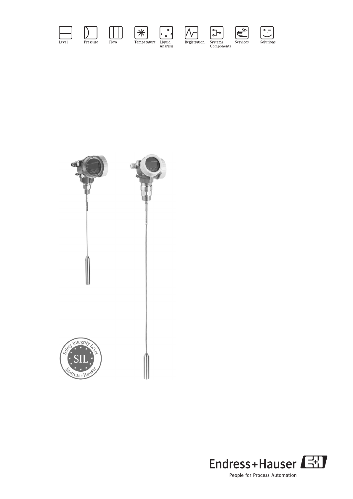
Levelflex FMP56, FMP57
Guided Level-Radar
Level measurmenet in bulk solids
Application
• FMP56 - economically attractive basic device for
common bulk solids applications in small silos and
tanks.
• FMP57 - premium device for level measurement in
bulk solids.
• Process connection starting 3/4" thread or flange
• Tensile load limit of rope probes up to 30 kN
• Measuring range up to 45 m (148 ft)
• Temperature range:
–40 to +150 °C (–40 to +302 °F)
• Pressure range: –1 to 16 bar (–14.5 to 232 psi)
• The following interfaces are available for system
integration:
– HART with 4...20 mA analog
– PROFIBUS PA
• Used for level monitoring (MIN, MAX, range) up to
SIL 2, independently assessed by TÜV as per
IEC 61508
Your benefits
• Reliable measuring:
– in dusty atmosphere
– in high and narrow silos
– in vessels and obstacles
• High availablility
• Integrated data memory
• Factory precalibrated
• Intuitive, menu-guided operating concept in national
languages
• Simple integration into control or asset management
systems
• Exact instrument and process diagnosis to assist fast
decisions
• Approvals: ATEX, IEC Ex, FM, CSA
TI01004F/00/EN/05.10
71112505
Page 2

Table of contents Levelflex FMP56, FMP57
Table of contents
Important document information ................ 3
Document conventions ........................... 3
Function and system design .................... 4
Measuring principle ............................. 4
Measuring system .............................. 6
Input ..................................... 8
Measured variable .............................. 8
Measuring range ............................... 8
Blocking distance .............................. 9
Measuring frequency spectrum ...................... 9
Output .................................... 9
Output signal ................................. 9
Signal on alarm ............................... 10
Linearization ................................ 10
Galvanic isolation ............................. 10
Protocol-specific data ........................... 10
Auxiliary energy ........................... 12
Electrical connection ........................... 12
Supply voltage ............................... 15
Terminals .................................. 16
Cable entries ................................ 16
Cable specification ............................. 16
Device plug connectors .......................... 16
Power consumption ............................ 16
Current consumption ........................... 17
Power supply failure ............................ 17
Load ..................................... 17
Potential equalization ........................... 18
Overvoltage protection .......................... 18
Performance characteristics ................... 18
Reference operating conditions ..................... 18
Maximum measured error ........................ 18
Resolution .................................. 19
Reaction time ................................ 19
Influence of ambient temperature ................... 20
Operating conditions: Process ................. 31
Process temperature range ........................ 31
Process pressure limits .......................... 31
Materials in contact with process .................... 31
Dielectric constant ............................. 32
Extension of the rope probes through tension and temperature . 32
Mechanical construction ..................... 33
Design, dimensions ............................ 33
Tolerance of probe length ........................ 36
Weight .................................... 36
Material ................................... 36
Human interface ........................... 38
Operating concept ............................. 38
Display elements .............................. 38
Operating elements ............................ 38
Additional functionality .......................... 38
On-site operation ............................. 38
Remote operation ............................. 39
System integration ............................. 40
Certificates and approvals .................... 43
CE mark ................................... 43
Ex approval ................................. 43
Functional Safety (in preparation) .................... 43
Marine certificate (in preparation) ................... 43
Telecommunications ........................... 43
CRN approval (in preparation) ...................... 43
Other standards and guidelines ..................... 43
Ordering information ........................ 44
Compact device Levelflex ........................ 44
Product structure FMP56, FMP57 ................... 44
Accessories ............................... 48
Device-specific accessories ........................ 48
Communication-specific accessories .................. 49
Service-specific accessories ........................ 50
System components ............................ 50
Operating conditions: Installation .............. 20
Suitable mounting position ........................ 20
Additional mounting hints ........................ 21
Documentation ............................ 51
Standard documentation ......................... 51
Supplementary documentation ..................... 51
Certificates ................................. 51
Operating conditions: Environment ............. 29
Ambient temperature range ....................... 29
Ambient temperature limits ....................... 29
Storage temperature ............................ 30
Climate class ................................ 30
Degree of protection ............................ 30
Vibration resistance ............................ 30
Cleaning the probe ............................ 30
Electromagnetic compatibility (EMC) ................. 30
Registered trademarks ....................... 52
Patents .................................. 52
2 Endress+Hauser
Page 3

Levelflex FMP56, FMP57
)
*
-
.
Important document information
Document conventions Electrical symbols
Symbol Meaning
Direct current
A terminal to which DC voltage is applied or through which direct current flows.
A0011197
Alternating current
A0011198
A terminal to which alternating voltage (sine-wave) is applied or through which alternating current flows.
Ground connection
A grounded terminal which, as far as the operator is concerned, is grounded via a grounding system.
A0011200
Protective ground connection
A terminal which must be connected to ground prior to establishing any other connections.
A0011199
Equipotential connection
A connection that has to be connected to the plant grounding system: This may be a potential equalization
A0011201
line or a star grounding system depending on national or company codes of practice.
Symbols and notation for certain types of information
Symbol
Meaning
Allowed
Indicates procedures, processes or actions that are allowed.
A0011182
Preferred
Indicates procedures, processes or actions that are preferred.
A0011183
Forbidden
Indicates procedures, processes or actions that are forbidden.
A0011184
Tip
Indicates additional information.
A0011193
Reference to documentation
Refers to the corresponding device documentation.
A0011194
Reference to page
Refers to the corresponding page number.
A0011195
Reference to graphic
Refers to the corresponding graphic number and page number.
A0011196
Symbols and notation in graphics
Symbol
1,2,3 ...
A, B, C, ...
A-A, B-B, C-C, ...
Meaning
Item numbers
Views
Sections
Hazardous area
Indicates a hazardous area.
A0011187
Safe area (non-hazardous area)
Indicates a non-hazardous location.
A0011188
Endress+Hauser 3
Page 4

Function and system design
F
L
D
E
100%
0%
LN
R
Measuring principle Level measurement
The Levelflex is a "downward-looking" measuring system that functions according to the ToF method (ToF =
Time of Flight). The distance from the reference point to the product surface is measured. High-frequency pulses
are injected to a probe and led along the probe. The pulses are reflected by the product surface, received by
the electronic evaluation unit and converted into level information. This method is also known as TDR (Time
Domain Reflectometry).
Levelflex FMP56, FMP57
A0012838
LN = probe length R = reference point of measurement
D = distace E = empty calibration (= zero)
L = level F = full calibration (= span)
Dielectric constant
The dielectric constant (DC) of the medium has a direct impact on the degree of reflection of the highfrequency
pulses. In the case of large DC values, such as for water or ammonia, there is strong pulse reflection while,
with low DC values, such as for hydrocarbons, weak pulse reflection is experienced.
Input
The reflected pulses are transmitted from the probe to the electronics. There, a microprocessor analyzes the
signals and identifies the level echo which was generated by the reflection of the high-frequency pulses at the
product surface. This clear signal detection system benefits from over 30 years' experience with pulse timeofflight procedures that have been integrated into the development of the PulseMaster® software.
The distance D to the product surface is proportional to the time of flight t of the impulse:
D = c · t/2,
where c is the speed of light.
Based on the known empty distance E, the level L is calculated:
L = E – D
Reference point for "E" see diagram above.
The Levelflex possesses functions for interference echo suppression that can be activated by the user. They
guarantee that interference echoes from e.g. internals and struts are not interpreted as level echoes.
4 Endress+Hauser
Page 5

Levelflex FMP56, FMP57
Engineering Procurement Installation
Commissioning
Operation
Maintenance Retirement
Output
The Levelflex is preset at the factory to the probe length ordered so that in most cases only the application
parameters that automatically adapt the device to the measuring conditions need to be entered. For models
with a current output, the factory adjustment for zero point E and span F is 4 mA and 20 mA, for digital outputs
and the display module 0 % and 100 %. A linearization function with max. 32 points, which is based on a table
entered manually or semi-automatically, can be activated on site or via remote operation. This function allows
the level to be converted into units of volume or mass, for example.
Life cycle of the product
A0013773-EN
å 1 Life cycle process
Engineering
• Universal measuring principle
• Measurement unaffected by medium properties
• Hardware and software developed according to SIL IEC 61508
• Genuine, direct interface measurement
Procurement
• Endress+Hauser being the world market leader in level measurement guarantees asset protection
• Worldwide support and service
Installation
• Special tools are not required
• Reverse polarity protection
• Modern, detachable terminals
• Main electronics protected by a separate connection compartment
Commissioning
• Fast, menu-guided commissioning in only 6 steps
• Plain text display in national languages reduces the risk of error or confusion
• Direct local access of all parameters
• Short instruction manual at the device
Operation
• Multi-echo tracking: Increased echo rate and analysis as well as automatic suppression of interfering echoes
• Diagnostics in accordance with NAMUR NE107
Maintenance
• HistoROM: Data backup for instrument settings and measured values
• Exact instrument and process diagnosis to assist fast decisions with clear details concerning remedies
• Intuitive, menu-guided operating concept in national languages saves costs for training, maintenance and
operation
• Housing cover can be opened in hazardous areas
Retirement
• Order code translation for subsequent models
• RoHS-conforming (Restriction of certain Hazardous Substances), unleaded soldering of electronic
components
• Environmentally sound recycling concept
Endress+Hauser 5
Page 6

Measuring system General notes on probe selection
• Normally, rope probes should be used for bulk solids, rod probes are only suitable for short measuring ranges
up to approx. 2 m (6.6 ft) in bulk solids. This applies above all to applications in which the probe is installed
laterally at an angle and for light and pourable bulk solids.
• In the case of large silos, the lateral pressure on the rope can be so high that a rope with plastic jacketing
must be used. We recommend PA-coated ropes be used for cereal products wheat, flour etc..
Probe selection
The various types of probe in combination with the process connections are suitable for the following
applications:
Levelflex FMP56
Type of probe Rope probe
Levelflex FMP56, FMP57
Feature 060 - Probe:
Max. probe length 12 m (40 ft)
Max. tensile loading capacity 12 kN
For application level measurement in bulk solids
Option:
LA 4 mm (316)
LB 1/6" (316)
NB 6 mm (PA>Steel)
NE 1/4" (PA>Steel)
A0011388
6 Endress+Hauser
Page 7

Levelflex FMP56, FMP57
Levelflex FMP57
Type of probe Rope probe Rod probe
A0011387
A0011388
Feature 060 - Probe: Option: Option:
LA 4 mm (316) AEAF16 mm (316L)
LB 1/6" (316)
LC 6 mm (316)
LD 1/4" (316)
NB 6 mm (PA>Steel)
NC 8 mm (PA>Steel)
NE 1/4" (PA>Steel)
NF 1/3" (PA>Steel)
Max. probe length 45 m (148 ft) 4 m (13 ft)
For application level measurement in bulk solids
Endress+Hauser 7
Page 8

Input
Levelflex FMP56, FMP57
Measured variable
The measured variable is the distance between the reference point and the product surface.
Subject to the empty distance entered "E" the level is calculated.
Alternatively, the level can be converted into other variables (volume, mass) by means of linearization (32
points).
Measuring range
The following table describes the media groups and the possible measuring range as a function of the media
group.
Levelflex FMP56
Measuring range
Media group
1 1.4...1.6 plastic powder 12 m (39 ft)
2 1.6...1.9 • plastic granulate
3 1.9...2.5 portland cement, plaster 12 m (39 ft) —
4 2.5...4 grain, seeds — 12 m (39 ft)
5 4...7 • naturally moist (ground) stones, ores
6 > 7 • metallic powder
DC (er)
• white lime, special cement
• sugar
flour — 12 m (39 ft)
• ground stones
• sand
• salt
• carbon black
• coal
Typical bulk solids
bare metallic
rope probes
1)
12 m (39 ft) 12 m (39 ft)
12 m (39 ft) 12 m (39 ft)
12 m (39 ft) 12 m (39 ft)
12 m (39 ft) 12 m (39 ft)
PA-coated
rope probes
—
1) Take into account restrictions for strongly damping media, e.g. ground material, wheat bran, silicic acid
Levelflex FMP57
Measuring range
Media group
1 1.4...1.6 plastic powder 4 m (13 ft)
2 1.6...1.9 • plastic granulate
3 1.9...2.5 portland cement, plaster 4 m (13 ft) 30 to 45 m (98 to 148 ft) —
4 2.5...4 grain, seeds 4 m (13 ft) — 25 to 35 m (82 to 115 ft)
5 4...7 • naturally moist (ground) stones, ores
6 > 7 • metallic powder
DC (er)
• white lime, special cement
• sugar
flour 4 m (13 ft) — 15 to 25 m (49 to 82 ft)
• ground stones
• sand
• salt
• carbon black
• coal
Typical bulk solids
bare metallic
rod probes
1)
4 m (13 ft) 25 to 30 m (82 to 98 ft) 12.5 to 15 m (41 to 49 ft)
4 m (13 ft) 45 m (148 ft) 25 to 35 m (82 to 115 ft)
4 m (13 ft) 45 m (148 ft) 35 to 45 m (115 to 148 ft)
4 m (13 ft) 45 m (148 ft) 45 m (148 ft)
bare metallic
rope probes
20 to 25 m (66 to 82
1)
ft)
PA-coated
rope probes
—
1) Take into account restrictions for strongly damping media, e.g. ground material, wheat bran, silicic acid
8 Endress+Hauser
Page 9

Levelflex FMP56, FMP57
F
UB
E
100%
0%
LN
R
• Reduction of the max. possible measuring range through buildup, above all of moist products.
• The respective lower group applies for very loose or loosened bulk solids.
Blocking distance
The upper blocking distance (= UB) is the minimum distance from the reference point of the measurement
(mounting flange) to the maximum level.
A0013628
R = reference point of measurement E = empty calibration (= zero)
LN = probe length F = full calibration (= span)
UB = upper blocking distance
Blocking distance (factory setting):
• with rod and rope probes up to 8 m (26 ft): 200 mm (8 in)
• with rod and rope probes exceeding a length of 8 m (26 ft): 0.025 * (length of probe)
The specified blocking distances are preset on delivery. Depending on the application these settings can
be changed.
Within the blocking distance, a reliable measurement can not be guaranteed.
Measuring frequency
100 MHz to 1,5 GHz
spectrum
Output
Output signal HART
Signal coding
Data transmission rate 1200 Baud
Galvanic isolation Ja
PROFIBUS PA
Signal coding
Data transmission rate 31,25 KBit/s, voltage mode
Galvanic isolation Ja
FSK ±0.5 mA over currency signal
Manchester Bus Powered (MBP)
Endress+Hauser 9
Page 10

Levelflex FMP56, FMP57
Signal on alarm
Maintenance information can be viewed via the following interfaces:
• Local display:
– Error symbol (in accordance with NAMUR Recommendation NE 107)
– Plain text display
• Current output: failsafe mode selectable (in accordance with NAMUR Recommendation NE 43):
– Minimum alarm: 3.6 mA
– Maximum alarm (= factory setting): 22 mA
• Digital interface such as HART communication or CDI service interface (in accordance with NAMUR
Recommendation NE 107)
Linearization
The linearization function of the Micropilot M allows the conversion of the measured value into any unit of
length or volume. Linearization tables for calculating the volume in cylindrical tanks are pre-programmed.
Other tables of up to 32 value pairs can be entered manually or semi-automatically.
Galvanic isolation
All circuits for the outputs are galvanically isolated from each other.
Protocol-specific data HART
Manufacturer ID
Device type ID 0x34
HART specification 6.0
Device description files (DTM,
DD)
HART load
HART device variables The measured values can be freely assigned to the device variables.
Supported functions
17 (0x11)
Information and files under:
• www.endress.com
• www.hartcom.org
Min. 250 W
Measured values for PV (primary variable)
• Level linearized
• Distance
• Electronic temperature
• Relative echo amplitude
Measured values for SV, TV, FV (second, third and fourth variable)
• Level linearized
• Distance
• Terminal voltage
• Electronic temperature
• Absolute echo amplitude
• Relative echo amplitude
• Calculated DC
• Burst mode
• Additional transmitter status
PROFIBUS PA
Manufacturer ID
Ident number 0x1558
Profile version 3.02
GSD file Information and files under:
GSD file version
17 (0x11)
• www.endress.com
• www.profibus.org
10 Endress+Hauser
Page 11

Levelflex FMP56, FMP57
Output values
Analog Input:
• Level linearized
• Distance
• Terminal voltage
• Electronic temperature
• Absolute echo amplitude
• Relative echo amplitude
• Calculated DC
Digital Input:
• Extended diagnostic blocks
• Status output PFS Block
Input values
Analog Output:
• Analog value from PLC (for sensor block external pressure and temperature)
• Analog value from PLC to be indicated on the display
Digital Output:
• Extended diagnostic block
1)
• Level limiter
• Sensor block measurement on
• Sensor block save history on
• Status output
Supported functions • Identification & Maintenance
Simple device identification via control system and nameplate
• Automatic Ident Number Adoption
GSD compatibility mode with respect to the previous device Levelflex M FMP4x
• Physical Layer Diagnostics
Installation check of the PROFIBUS segment and the Levfelflex FMP4x via terminal
voltage and telegram monitoring
• PROFIBUS Up-/Download
Up to 10 times faster reading and writing of parameters via PROFIBUS Up-/
Download
• Condensed Status
Simple and self-explanatory diagnostic information due to categorization of
diagnostic messages
1)
1) in preparation
Endress+Hauser 11
Page 12

Auxiliary energy
+
1
–
2
+
–
2
36
4...20mA
6
+
–
4
7
8
15
Electrical connection 2-wire, 4-20mA HART (FMP5x - **A...)
Without intgrated overvoltage protection
Levelflex FMP56, FMP57
A0011294
1
Terminal 4...20mA HART passive
2
Active barrier with power supply (e.g. RN221N): Observe terminal voltage (® ä 15)
3
HART communication resistor (³250 W): Observe maximum load (® ä 17)
4 Connection for Field Communicator 375/475 or Commubox FXA195
5
Analog display device: Observe maximum load (® ä 17)
6
Observe cable specification (® ä 16)
7 Potential equalization
8 Cable entry
12 Endress+Hauser
Page 13

Levelflex FMP56, FMP57
–
4
+
1
–
2
+
3
+
–
2
3
10
6
4
8
5
4...20mA
+
–
+
–
4...20mA
+
–
1
77
9
11
12
2-wire, 4-20 mA HART, 4...20mA
Without integrated overvoltage protection
A0013923
1
Cable entry for current output 1
2 Terminal for current output 1
3
Supply voltage for current output 1 (e.g. RN221N); Observe terminal voltage (® ä 16)
4
HART communication resistor (³ 250 W): Observe maximum load (® ä 17)
5 Connection for Field Communicator 375/475 or Commubox FXA195
6
Analog display device ; observe maximum load (® ä 17)
7
Observe cable specification (® ä 16)
8 Cable entry for current output 2
9 Terminal for current output 2
10
Supply voltage for current output 2 (e.g. RN221N); Obesrve terminal voltage (® ä 16)
11 Analog display device ; observe maximum load
12 Terminal for the potential equalization line
This version is also suited for single-channel operation. In this case, current output 1 must be used.
Endress+Hauser 13
Page 14

4-wire, 4-20 mA HART (FMP5x - **K/L...)
+
–
3
4
4...20mA
³ W250
5
6
7
AC/DC
2
9
11
8
1
5
10
+
1
–
2
–
4
+
3
+
1
–
2
4
3
1
2
–
4
+
3
Without integrated overvoltage protection
Levelflex FMP56, FMP57
A0011340
1
Terminal 4...20mA HART
2 Evaluation unit, e.g. PLC
3
HART communication resistor (³250 W): Observe maximum load (® ä 17)
4
Analog display device: Observe maximum load (® ä 17)
5
Observe cable specification (® ä 16)
6 Connection Field Communicator 375/475 or Commubox FXA195
7
Supply voltage: Observe terminal voltage (® ä 16)
8 Terminal supply voltage
9 Potential equalization
10 Cable entry for power supply
11 Cable entry for signal line
In order to ensure electromagnetic compatibility (EMC): Do not ground the device via the protective earth
conductor of the supply cable. Instead, ground the device via the process connection (flange or threaded
connection) or the external ground terminal .
PROFIBUS PA
14 Endress+Hauser
Terminals PROFIBUS PA
1
2 Cable screen
3 Cable entry
4 Potential equalization
A0011341
Page 15

Levelflex FMP56, FMP57
–
4
+
3
2
1
+
1
–
2
A0013759
1 Terminals switching output
2 Cable entry
Switching output
Function Open collector switching output
Switching behavior Binary (conductive or non-conductive), switches when the programmable switch point is
reached
Failure mode non-conductive
Eectrical connection values U = 10.4 to 35 VDC, I = 0 to 70 mA
Insulation voltage floating, Insulation voltage 1 350 VDC to power supply aund 500 VAC to ground
Switch point freely programmable, separately for switch-on and switch-off point
Switching delay freely programmable from 0 to 100 sec. , separately for switch-on and switch-off point
Number of switching cycles corresponds to the measuring cycle
Signal source
device variables
Number of switching cycles unlimited
• Level linearized
• Distance
• Terminal voltage
• Electronic temperature
• Relative echo amplitude
Supply voltage
An external power supply is required.
Various supply units can be ordered from Endress+Hauser: see "Accessories" section (® ä 50)
2-wire, 4-20mA HART, passive
"Power Supply, Output"
A: 2-wire; 4-20mA HART 1 11.5 to 35 V Non-Ex, Ex nA, CSA GP
C: 2-wire; 4-20mA HART, 4-20mA 1 13.5 to 30 V all
1) Feature 020 of the product structure
2) Feature 010 of the product structure
1)
Outputs Terminal voltage "Approval"
11.5 to 32 V Ex ic
11.5 to 30 V Ex ia / IS
13.5 to 30 V Ex d / XP, Ex ic(ia), Ex tD / DIP
2 12 to 30 V all
2)
Load (® ä 17)
Endress+Hauser 15
Page 16

4-wire, 4-20mA HART, active
2
1
3
4
+
–
nc
2
1
3
4
+
–
nc
Levelflex FMP56, FMP57
Terminals
Cable entries
"Power supply; Output"
1)
Terminal voltage
K: 4-wire 90-253VAC; 4-20mA HART 90 to 253 VAC (50 to 60 Hz)
L: 4-wire 10,4-48VDC; 4-20mA HART 10.4 to 48 V
DC
1) Feature 020 of the product structure
PROFIBUS PA
"Power supply; Output"
G: 2-wire; PROFIBUS PA, switch output 9 to 32 V
1) Feature 020 der Produkstruktur
1)
Terminal voltage
DC
Plug-in spring terminals for wire cross-sections 0.5 to 2.5 mm2 (20 to 14 AWG)
• Cable gland (not for Ex d):
–
Plastics M20x1,5 with cable Æ 5 to 10 mm (0.2 to 0.39 in): non-Ex, ATEX/IECEx/NEPSI Ex ia/ic/nA
–
Metal M20x1,5 with cable Æ 7 to 10 mm (0.28 to 0.39 in): dust-Ex, FM IS, CSA IS, CSA GP
• Thread for cable entry:
– ½" NPT
– G ½"
– M20 × 1.5
• Connector (only for non-Ex, Ex ic, Ex ia): M12 or 7/8"
Cable specification
Device plug connectors
•
For ambiente temperature TU³60 °C (140 °F): use cable for temperature TU +20 K.
• A normal device cable suffices if only the analog signal is used.
• A shielded cable is recommended if using the HART protocol. Observe grounding concept of the plant.
For the versions with fieldbus plug connector (M12 or 7/8"), the signal line can be connected without
opening the housing.
Pin assignment of the M12 plug connector
Pin Meaning
1 Ground
2 Signal +
3 Signal -
A0011175
4 not connected
Pin assignment of the 7/8" plug connector
Pin Meaning
1 Signal -
2 Signal +
3 not connected
A0011176
4 Ground
Power consumption
16 Endress+Hauser
min. 60 mW, max. 900 mW
Page 17

Levelflex FMP56, FMP57
R [ ]W
[V]U
0
10
11.5 22.5
20 30 35
0
500
R [ ]W
[V]U
0
10
13.5 24.5
20 30
0
500
Current consumption HART
Power supply failure
Load
Nominal current
3.6 to 22 mA, the start-up current for multidrop mode can be parametrized (is set to
3.6 mA on delivery)
Breakdown signal (NAMUR
adjustable
NE43)
PROFIBUS PA
Nominal current
Error current FDE (Fault
Disconnection Electronic)
max. 15 mA
0 mA
• Configuration is retained in the HistoROM (EEPROM).
• Error messages (incl. value of operated hours counter) are stored.
Feature 20 "Power Supply, Output", Option A "2-wire; 4-20mA HART"
Outputs Terminal voltage Feature 010 - Approval
1 11.5 to 35 V Non-Ex, Ex nA, CSA GP
11.5 to 32 V Ex ic
11.5 to 30 V Ex ia / IS
Feature 20 "Power Supply, Output", Option A "2-wire; 4-20mA HART"
Outputs Terminal voltage Feature 010 - Approval
1 13.5 to 30 V Ex d / XP, Ex ic(ia), Ex tD / DIP
A0014076
A0014077
Feature 20 "Power Supply, Output", Option C "2-wire; 4-20mA HART, 4-20mA"
Outputs Terminal voltage Feature 010 "Approval"
1 13.5 to 30 V all
Endress+Hauser 17
Page 18

Levelflex FMP56, FMP57
R [ ]W
[V]U
0
10
12 23
20 30
0
500
Feature 20 "Power Supply, Output", Option C "2-wire; 4-20mA HART, 4-20mA"
Outputs Terminal voltage Feature 010 "Approval"
2 12 to 30 V all
A0014078
Potential equalization
Overvoltage protection
Reference operating conditions
Maximum measured error
No special measures for potential equalization are required.
If the device is designed for hazardous areas, observe the information in the documentation "Safety
Instructions" (XA, ZD).
If the measuring device is used for level measurement in flammable liquids which requires the use of overvoltage
protection according to DIN EN 60079-14, standard for test procedures 60060-1 (10 kA, pulse 8/20 ms),
overvoltage protection has to be ensured by one of the following measures:
• Integrated overvoltage protection (in preparation);
Product structure: Feature 610 "Accessory mounted", option NA "Overvoltage protection".
• External overvoltage protection, e.g. Endress+Hauser's HAW262Z.
Performance characteristics
• Temperature = +24 °C (+75 °F) ±5 °C (±9 °F)
• Pressure = 960 mbar abs. (14 psia) ±100 mbar (±1.45 psi)
• Humidity = 60 % ±15 %
• Reflection factor ≥ 0,8 (metal plate for rod and rope probe with min. 1 mm (0.04 in) diameter)
•
Flange for rod or rope probe ³ 300 mm (12 in) diameter
•
Abstand zu Hindernissen ³ 1 m (40 in)
Typical data under reference operating conditions: DIN EN 61298-2, percentage values in relation to the span.
Output:
Sum of non-linearity,
nonrepeatability and hysteresis
Offset / Zero
1) Add error of the analogous value to the digital value.
digital analog
Level measurement:
•
Measuring range up to 15 m (49 ft): ±2 mm (0.08 in)
•
Measuring range >15 m (49 ft): ±10 mm (0.39 in)
±4 mm (0.16 in)
±0.02 %
±0.03 %
If the reference conditions are not met, the offset/zero point arising from the mounting situation may be up to
±12 mm (0.47 in) for rope and rod probes. This additional offset/zero point can be compensated for by entering
a correction (parameter "level correction") during commissioning.
18 Endress+Hauser
1)
Page 19

Levelflex FMP56, FMP57
rodprobeandcoaxprobe
-80
-60
-40
-20
0
20
40
60
80
0 50 100 150 200 250 300
distancefromprobeend[mm]
sum of non-linearity, non-repeatability
and hysteresis [mm]
DC=2
DC>7
ropeprobe
-80
-60
-40
-20
0
20
40
60
80
0 50 100 150 200 250 300
distancefromprobeend[mm]
sum of non-linearity, non-repeatability
and hysteresis [mm]
DC>7
3mm
0mm
-3mm
100mm 200mm
10mm
-10mm
20mm
-20mm
30mm
-30mm
40mm
-40mm
referencepointofmeasurement
maximummeasurederror
Differing from this, the following measuring error is present in the vicinity of the lower probe end:
A0014154-EN
If for rope probes the DC value is less than 7, then measurement is not possible in the area of the straining
weight (0 to 250 mm from end of probe; lower blocking distance).
Resolution
Differing from this, the following measuring error is present in the vicinity of the upper probe end
(rod/rope only):
A0014155-EN
• digital: 1 mm
•
analog: 1 mA
Reaction time
Endress+Hauser 19
The reaction time can be parametrized. The fastest possible reaction time is given by the measuring rate:
Probe length
<10 m (33 ft)
up to 40 m (131 ft)
Level measurement
3.6 measurements/second
³2.7 measurements/second
Page 20

Levelflex FMP56, FMP57
A
C
1 32
4
B
Influence of ambient temperature
Suitable mounting position
The measurements are carried out in accordance with EN 61298-3
• digital (HART, PROFIBUS PA, FOUNDATION Fieldbus): average TK = 0.6 mm/10 K
• analog (current output):
– zero point (4 mA): average TK = 0.02 %/10 K
– span (20 mA): average TK = 0.05 %/10 K
Operating conditions: Installation
Mounting distances
• Distance (A) between wall and rod or rope probe:
– for smooth metallic walls: > 50 mm (2")
– for plastic walls: > 300 mm (12") mm to metallic parts outside the vessel
– for concrete walls: > 500 mm (20") , otherwise the available measuring range may be reduced.
• Distance (B) between rod or rope probe and internal fittings in the vessel: > 300 mm (12")
• Distance (C) from end of probe to bottom of the vessel: > 10 mm (0.4").
Additional conditions
• When mounting in the open: Use a weather protection cover (1)
• In metallic vessels: Do not mount the probe in the center of the vessel (2).
• Do not mount the probe in the filling curtain (3)
• Avoid buckling the rope probe during installation or operation (e.g. through product movement against silo
wall) by selecting a suitable mounting location.
• Check the probe regularly for defects.
With suspended rope probes (probe end not fixed at the bottom) the distance between the probe rope
and internal fittings in the tank must not fall below 300 mm (12") during the entire process. A sporadic
contact between the probe weight and the cone of the vessel, however, does not influence the
measurement as long as the dielectric constant of the medium is at least DC = 1.8.
When mounting the electronics housing into a recess (e.g. in a concrete ceiling), observe a minimum
distance of 100 mm (4 inch) between the cover of the terminal compartment and the wall.
Wall and pipe mounting
Endress+Hauser offers a mounting bracket for installing the device on pipes or on walls.
20 Endress+Hauser
A0012851-DE
Page 21

Levelflex FMP56, FMP57
Ordering information: Feature 600 "Probe Design", Option MB "Sensor remote, 3m/9ft cable" (® ä 47).
Dimensions (® ä 34).
Additional mounting hints Bending strength of rod probes
Sensor Feature 060 Probe Bending strength [Nm]
FMP57 AE, AF Rod 16mm (0.63") 316L 30
Tensile load limit of rope probes
Sensor Feature 060 Probe Tensile load limit [kN] Max. rupture load [kN]
FMP56 LA, LB Rope 4mm (1/6") 316 12 16
NB, NE Rope 6mm (1/4") PA>Steel 12 16
FMP57 LA, LB Rope 4mm (1/6") 316 12 16
LC, LD Rope 6mm (1/4") 316 30 35
NB, NE Rope 6mm (1/4") PA>Steel 12 16
NC, NF Rope 8mm (1/3") PA>Steel 30 35
1) The ceiling of the silo must be designed to withstand this load.
1)
Tensile load
Bulk solids exert tensile forces on rope probes whose height increases with:
• the length of the probe, i.e. max. cover
• the bulk density of the product,
• the silo diameter and
• the diameter of the probe rope
The following diagrams show typical loads for frequently occurring bulk solids as reference values. The
calculation is performed for the following conditions:
• Suspended probe (probe end not fixed at the bottom)
• Free-flowing bulk solid, i.e. mass flow. A calculation for core flow is not possible. In the event of collapsing
cornices, considerably higher loads can occur.
• The specification for tensile forces contains the safety factor 2, which compensates for the normal fluctuation
range in pourable bulk solids.
Endress+Hauser 21
Page 22

Levelflex FMP56, FMP57
0 5 10 15 20 25 30 35
0
5
10
15
20
25
30
pulling force, 6 mm rope [kN]
level [m]
silica sand
smooth metallic walls
silo diameter 12 m
silo diameter 9 m
silodiameter6m
silodiameter3m
0
2
4
6
8
10
12
14
16
18
20
pulling force, 4 mm rope [kN]
0 5 10 15 20 25 30 35
0
1
2
3
4
5
6
7
8
9
pulling force, 6 mm rope [kN]
level [m]
polyethylene pellets
smooth metallic walls
silo diameter 12 m
silo diameter 9 m
silodiameter6m
silodiameter3m
0
1
2
3
4
5
6
pulling force, 4 mm rope [kN]
0 5 10 15 20 25 30 35
0
2
4
6
8
10
12
14
16
18
pulling force, 6 mm rope [kN]
level [m]
wheat
smooth metallic walls
silo diameter 12 m
silo diameter 9 m
silodiameter6m
silodiameter3m
0
2
4
6
8
10
12
pulling force, 4 mm rope [kN]
0 5 10 15 20 25 30 35
0
5
10
15
20
25
30
pulling force, 6 mm rope [kN]
level [m]
cement
smooth metallic walls
silo diameter 12 m
silo diameter 9 m
silodiameter6m
silodiameter3m
0
2
4
6
8
10
12
14
16
18
20
pulling force, 4 mm rope [kN]
Since the tensile forces are also heavily dependent on the viscosity of the product, a higher safety factor is
necessary for highly viscous products and if there is a risk of cornice buildup. In critical cases it is better to use
a 6 mm rope instead of a 4 mm one.
The same forces also act on the silo cover. On a fixed rope, the tensile forces are definitely greater, but this can
not be calculated. Observe the tensile strength of the probes.
Options for reducing the tensile forces:
• Shorten the probe.
• If the maximum tensile load is exceeded, check whether it would be possible to use a non-contact Ultrasonic
or Level-Radar device.
A0014133-EN
22 Endress+Hauser
Page 23

Levelflex FMP56, FMP57
<<150
( 6)
mm (in)
<ØØ150
( 6)<
1 2
Type of probe installation
• Probes are mounted to the process connection with threaded connections or flanges and are usually also
secured with these. If during this installation there is the danger that the probe end moves so much that it
touches the tank floor or cone at times, the probe must, if necessary, be shortened and fixed down. The
easiest way to fix the rope probes is to screw them to the internal thread on the lower end of the weight
(® ä 25).
• The ideal installation is mounting in a screwed joint / screw-in sleeve which is internally flush with the
container ceiling.
• Alternative: nozzle mounting
A0012526
1
Mounting with screwed joint; flush with the container ceiling
2 Nozzle mounting
•
Permissible nozzle diameter: £ 150 mm (6 in).
For larger diameters the near range measuring capability may be reduced.
•
Permissible nozzle height: £ 150 mm (6 in).
For a larger height the near range measuring capability may be reduced.
Extension rod for FMP57
If - for installations in nozzles > 150 mm (6 in) - the probe could touch the lower nozzle edge due to moving
materials in the container, we recommend using an extension rod with or without centering disk (HMP40, see
"Accessories").
This accessory consists of the extension rod corresponding to the nozzle height, on which a centering
disk is also mounted if the nozzles are narrow or when working in bulk solids. This component is delivered
separately from the device. Please order the probe length correspondingly shorter.
Only use centering disks with small diameters (DN40 and DN50) if there is no significant build-up in the
nozzle above the disk. The nozzle must not become clogged by the product.
Installation in nozzles ³ DN300
If installation in ≥ 300mm/12" nozzles is unavoidable, installation must be carried out in accordance with the
sketch on the right.
Endress+Hauser 23
Page 24

1
2
3
4
1 Lower edge of the nozzle
≥≥100
4
≥≥100
4
mm(in)
ø80...150
(ø3.2...6)
1
3
2
2
Approx. flush with the lower edge of the nozzle (± 50 mm/2")
3 Plate
4
Pipe Æ 150 to 180 mm (6 to 7 inch)
Nozzle diameter Plate diameter
300 mm (12") 280 mm (11")
³ 400 mm (16") ³ 350 mm (14")
Levelflex FMP56, FMP57
A0014199
Installation in concrete silos
Installation, for example, into a thick concrete ceiling should be made flush with the lower edge. Alternatively,
the probe can also be installed into a pipe that must not protrude over the lower edge of the silo ceiling. The
pipe should kept at a minimum length. Installation suggestions see diagram.
Metal sheet
1
2 Metal tube
3 Extension rod / Centering HMP40 (see "Accessories")
Note for installations with rod extension/center washer (accesories): Strong dust generation can lead to buildup behind the center washer. This can cause an interference signal. For other installation possibilities please
contact Endress+Hauser.
24 Endress+Hauser
A0014138
Page 25

Levelflex FMP56, FMP57
1
A
C
B
2
Securing rod probes
• Rod probes must be supported if there is a horizontal flow (e.g. from an agitator) or in the case of strong
vibrations.
• Rod probes may only be supported at the end of the probe.
NOTICE
Poor grounding of the end of probe may cause measuring errors.
►
Apply a narrow sleeve which has good electrical contact to the probe.
NOTICE
Welding may damage the electronics.
►
Before welding: Ground the probe and dismount electronics.
Securing rope probes
A0012609
A
Sag of the rope: ³ 1 cm per 1m of the probe length (0.12 inch per 1 ft of the probe length)
B: Mounting and contact with a bolt
C
Mounting kit isolated (® ä 49)
1 Reliably grounded end of probe
2 Reliably isolated end of probe
• The end of the probe needs to be secured under the following conditions:
– if otherwise the probe sporadically comes into contact with the wall of the vessel, the outlet cone, internal
fittings or other parts of the installation.
– if otherwise the probe sporadically gets close to a concrete wall (minimum distance 0.5 m / 20 inch).
• The end of probe can be secured at its internal thread
– for 4 mm (1/6") rope: M 14
– for 6 mm (1/4") rope: M 20
• Preferably use the 6 mm (1/4") rope probe due to the higher tensile strength when fixing a rope probe.
• The fixing must be either reliably grounded or reliably insulated. If it is not possible to mount the probe
weight with a reliably insulated connection, it can be secured using an isolated eyelet, which is available as
an accessory (® ä 49).
• In order to prevent an extremely high tensile load (e.g. due to thermal expansion) and the risk of rope crack,
the rope has to be slack. Make the rope longer than the required measuring range such that there is a sag in
the middle of the rope that is ≥ 1cm/(1 m rope length) [0.12 inch/(1 ft rope length)]. Tensile load limit of
rope probes: (® ä 21)
Endress+Hauser 25
Page 26

Installation from the side
Ø16
(Ø0.63)
Ø17...18
(Ø0.67...0.71)
Ø<26
(Ø<1.02)
mm(in)
Levelflex FMP56, FMP57
A0014140
• If installation from above is not possible, the Levelflex can also be mounted from the side.
•
In this case, always fix the rope probe (® ä 25) .
•
Support rod probe if the lateral loadbearing capacity is exceeded (® ä 21). Only fix rod probes at the probe
end (® ä 25).
Installation in underground tanks
A0014142
Use coax probe for nozzles with large diameters in order to avoid reflections at the nozzle wall.
26 Endress+Hauser
Page 27

Levelflex FMP56, FMP57
1
2
MAX
max.150°C(302°F)
1
Mounting in non-metallic vessels
A0012527
1 Non-metallic vessel
2 Metal sheet or metal flange
To measure, Levelflex with a rod probe needs a metallic surface at the process connection. Therefore:
• Select an instrument version with metal flange (minimum size DN50/2").
• Or: mount a metal sheet with a diameter of at least 200 mm (8") to the probe at the process connection. Its
orientation must be perpendicular to the probe.
Installation with heat insulation
• If process temperatures are high, the device must be included in normal tank insulation to prevent the
electronics heating up as a result of heat radiation or convection.
• The insulation may not exceed beyond the points labeled "MAX" in the drawings.
Process connection with thread
1
Tank insulation
A0014143
Endress+Hauser 27
Page 28

Process connection with flange
40(1.57)
MAX
max.150°C(302°F)
1
1 Tank insulation
Levelflex FMP56, FMP57
A0014144
28 Endress+Hauser
Page 29

Levelflex FMP56, FMP57
[°C]([°F]) T
a
[°C]([°F]) T
a
[°C]
([°F])
T
p
[°C]
([°F])
T
p
+120
(+248)
+120
(+248)
+82
(+180)
+79
(+174)
+74
(+165)
-40
(-40)
-40
(-40)
GT20: +74(+165)
GT20: +70(+158)
GT18: +71(+160)
GT18: +68(+154)
GT19: +58(+136)
GT19: +65(+149)
+80(+176)
GT18/20: +79(+174)
GT19: +74(+165)
-40(-40)
-40(-40)
T
a
T
p
4 20mA HART–
A:
4 20mA HART–
4 20mA–
C:
90–253VAC
K:
10.4–48VDC
L:
Operating conditions: Environment
Ambient temperature range
Ambient temperature limits
Measuring device
Local display
–40 to +80 °C (–40 to +176 °F)
–20 to +70 °C (–4 to +158 °F), the readability of the display may be impaired at
temperatures outside the temperature range.
When operating the device in the open with strong sunlight:
• Mount the device in a shady position.
• Avoid direct sunlight, especially in warmer regions.
• Use a weather protection cover (see accessories).
With a temperature (Tp) at the process connection the admissible ambient temperature (Ta) is reduced according
to the following diagram (temperature derating):
Temperature derating for FMP56 with threaded connection G¾ or NPT¾
A0014122
GT18 = stainless steel housing
GT19 = plastic housing
GT20 = aluminum housing
Endress+Hauser 29
A = 1 current output
C = 2 current outputs
K, L = 4-wire
Ta = ambient temperature
Tp = temperature at the process connection
Page 30

Temperature derating for FMP57
[°C]([°F]) T
a
[°C]([°F]) T
a
[°C]
([°F])
T
p
[°C]
([°F])
T
p
+150
(+302)
+150
(+302)
+82
(+180)
+79
(+174)
+74
(+165)
-40
(-40)
-40
(-40)
GT20: +71(+160)
GT20: +67(+153)
GT18: +69(+156)
GT18: +65(+149)
GT19: +55(+131)
GT19: +57(+135)
+80(+176)
GT18/20: +79(+174)
GT19: +74(+165)
-40(-40)
-40(-40)
T
a
T
p
4 20mA HART–
A:
4 20mA HART–
4 20mA–
C:
90–253VAC
K:
10.4–48VDC
L:
Levelflex FMP56, FMP57
A0013634
Storage temperature
Climate class
Degree of protection
GT18 = stainless steel housing
GT19 = plastic housing
GT20 = aluminum housing
–40 to +80 °C (–40 to +176 °F)
DIN EN 60068-2-38 (test Z/AD)
• With closed housing tested according to:
A = 1 current output
C = 2 current outputs
K, L = 4-wire
Ta = ambient temperature
Tp = temperature at the process connection
– IP68, NEMA6P (24 h at 1.83 m under water surface)
– IP66, NEMA4X
• With open housing: IP20, NEMA1 (also ingress protection of the display)
Degree of protection IP68 NEMA6P applies for M12 PROFIBUS PA plugs only when the PROFIBUS cable
is plugged in and is also rated IP68 NEMA6P.
Vibration resistance
Cleaning the probe
Electromagnetic compatibility (EMC)
30 Endress+Hauser
DIN EN 60068-2-64 / IEC 68-2-64: 20 to 2 000 Hz, 1 (m/s2)2/Hz
Depending on the application, contamination or buildup can accumulate on the probe. A thin, even layer only
influences measurement slightly. Thick layers can dampen the signal and then reduce the measuring range.
Severe, uneven buildup, adhesion e.g. through crystallization, can lead to incorrect measurement. In this case,
we recommend that you use a non-contact measuring principle, or check the probe regularly for soiling.
Electromagnetic compatibility to EN 61326 and NAMUR Recommendation EMC (NE21). Details are provided
in the Declaration of Conformity. A standard installation cable is sufficient if only the analog signal is used.
Use a shielded cable when working with a superimposed communications signal (HART).
Maximum measured error: < 0.5 % of the span.
When installing the probes in metal and concrete tanks and when using a coax probe:
• Interference emission to EN 61326 - x series, electrical equipment Class B.
• Interference immunity to EN 61326 - x series, requirements for industrial areas and NAMUR
Recommendation NE 21 (EMC)
The measured value can be affected by strong electromagnetic fields when installing rod and rope probes
without a shielding/metallic wall, e.g. in plastic and wooden silos.
• Interference emission to EN 61326 - x series, electrical equipment Class A.
• Interference Immunity: the measured value can be affected by strong electromagnetic fields.
Page 31

Levelflex FMP56, FMP57
1
5
6
4
1
2
7
5
4
1
3
7
2
5
4
Operating conditions: Process
Process temperature range
Process pressure limits
The maximum permitted temperature at the process connection is determined by the O-ring version ordered:
Device O-ring material Process temperature
FMP56 FKM (Viton GLT) –30 to +120 °C (–22 to +248 °F)
EPDM –40 to +120 °C (–40 to +248 °F)
FMP57 FKM (Viton GLT) –30 to +150 °C (–22 to +302 °F)
EPDM –40 to +120 °C (–40 to +248 °F)
The medium temperature can be higher.
However, when using rope probes the stability of the probe rope is reduced by structural changes at
temperatures over 350 °C (662 °F).
Device
FMP56, FMP57 –1 to 16 bar (–14.5 to 232 psi)
Process pressure
This range may be reduced by the selected process connection. The pressure rating (PN) specified on the
flanges refers to a reference temperature of 20 °C, for ASME flanges 100 °F. BPay attention to pressuretemperature dependencies.
Please refer to the following standards for the pressure values permitted for higher temperatures:
• EN 1092-1: 2001 Tab. 18
With regard to their temperature stability properties, the materials 1.4435 and 1.4404 are grouped
under 13E0 in EN 1092-1 Tab. 18. The chemical composition of the two materials can be identical.
• ASME B 16.5a - 1998 Tab. 2-2.2 F316
• ASME B 16.5a - 1998 Tab. 2.3.8 N10276
• JIS B 2220
Materials in contact with process
Threaded connection
G¾, NPT¾ G1½, NPT1½
A0013890
• Endress+Hauser supplies DIN/EN flanges and threaded process connections made of stainless steel
according to AISI 316L (DIN/EN material number 1.4404 or 1.4435). With regard to their temperature
stability properties, the materials 1.4404 and 1.4435 are grouped under 13E0 in EN 1092-1 Tab. 18.
The chemical composition of the two materials can be identical.
•
Further material specifications (® ä 36)
Levelflex FMP56. FMP57
Flange No. Material
1 304 (1.4301)
2 316L (1.4404)
3 316L (1.4435/1.4404)
4 Nordlock washer: 1.4547
5 1.4462, Duplex CR22
A0013888
A0013889
6 PPS-GF40
7 PEEK GF30
Endress+Hauser 31
Page 32

Rod probe Rope probe
2
4
1.1
6
3.1
7
5
1.1
6
3.1
7
4
1.2
6
3.2
7
5
1.2
6
3.2
7
Æ 16 mm (2/3") Æ 6 mm (1/4")
A0013891
A0013892
Æ 8 mm (1/3")
coated
A0013893
Levelflex FMP56, FMP57
Æ 4 mm (1/6")
A0013894
Æ 6 mm (1/4")
coated
No. Material
1.1
1.2 316L (1.4404)
3.1 304 (1.4301)
3.2 316L (1.4404)
A0013895
Levelflex FMP56, FMP57
304 (1.4301)
2 316L (1.4435/1.4404)
4 316 (1.4401)
5 Rope: galvanized steel
Coating: PA 12 (Vestamid L 1940)
6 Set screw: A4-70
7 Screw for tightening: A2-70
Dielectric constant
Extension of the rope probes through tension and temperature
Rod and rope probe: DC (er) ³ 1.4
4 mm rope:
• Elongation through tension: at max. permitted tensile load (12 KN): 11 mm / m rope length
• Elongation through temperature increase from 30 °C (86 °F) to 150 °C (302 °F): 2 mm / m rope length
6 mm rope:
• Elongation through tension: at max. permitted tensile load (30 KN): 13 mm / m rope length
• Elongation through temperature increase from 30 °C (86 °F) to 150 °C (302 °F): 2 mm / m rope length
32 Endress+Hauser
Page 33

Levelflex FMP56, FMP57
144(5.67)
141.9(5.59)
115.25(4.54)
ø108.5(ø4.27)
78(3.07)
90(3.54)
98(3.86)
ø103.5(ø4.07)
R100
163(6.42)
134.5(5.3)
ø106(ø4.17)
78(3.07) 90(3.54)
99.5(3.92)
ø106(ø4.17)
R100
144(5.67)
141.5(5.57)
117.1(4.61)
ø111(ø4.37)-1°
ø108.5(ø4.27)
78(3.07)
90(3.54)
97(3.82)
ø103.5(ø4.07)
R100
Mechanical construction
Design, dimensions Dimensions of the electronics housing
å 2 Housing GT18 (316L); Dimensions in mm (in)
A0011666
å 3 Housing GT19 (Plastics PBT); Dimensions in mm (in)
å 4 Housing GT20 (Alu coated); Dimensions in mm (in)
A0011346
A0011665
Endress+Hauser 33
Page 34

FMP56: Dimensions of process connection and probe
A
B
C D
LN
ø22 (ø0.87)ø22 (ø0.87)
mm (in)
ø4
(ø0.16)
ø6
(ø0.24)
150 (5.91)
68.8 (2.71)
25
(0.98)
ø59.35
(ø2.34)
SW36
AF36
SW10
AF10
SW10
AF10
SW10
AF10
150 (5.91)
M14M14
20 (0.79)
20 (0.79)
R
122
(4.8)
52
(2.05)
50
(1.97)
61
(2.4)
ø82.5
(ø3.25)
Levelflex FMP56, FMP57
Mounting bracket for probe design "Sensor remote" Feature 600)
A
B Thread ISO228 G3/4 or ANSI MNPT3/4 (Feature 100)
C Rope probe 4mm or 1/6" (Feature 060)
D Rope probe 6mm or 1/4", PA>Steel (Feature 060)
LN Length of probe
R Reference point of the measurement
34 Endress+Hauser
A0012781
Page 35

Levelflex FMP56, FMP57
A
B
C D
SW55
AF55
SW55
AF55
SW14
AF14
SW14
AF14
SW14
AF14
ø59.5
(ø2.34)
ø59.5
(ø2.34)
ø59.5
(ø2.34)
94.8(3.73)
25
(0.98)
26
(1.02)
94.8(3.73)
94.8(3.73)
E F G H
I
SW14
AF14
ø16
(ø0.63)
150(5.91)
SW14
AF14
ø6
(ø0.24)
ø4
(ø0.16)
ø8
(ø0.31)
ø6
(ø0.24)
SW14
AF14
SW14
AF14
SW14
AF14
150(5.91)
150(5.91)
150(5.91)
ø30
(ø1.18)
ø30
(ø1.18)
ø22
(ø0.87)
ø22
(ø0.87)
M14
M20
M20
M14
20(0.79)
20(0.79)
20(0.79)
20(0.79)
LN
mm(in)
R
122
(4.8)
52
(2.05)
50
(1.97)
61
(2.4)
ø82.5
(ø3.25)
FMP57: Dimensions of process connection and probe
Endress+Hauser 35
Mounting bracket for probe design "Sensor remote" (Feature 600)
A
B Thread ISO228 G1-1/2 (Feature 100)
C Thread ANSI MNPT1-1/2 (Feature 100)
D Flange ANSI B16.5, EN1092-1, JIS B2220 (Feature 100)
E Rod probe 16mm (Feature 060)
F Rope probe 6mm or 1/4" (Feature 060)
G Rope probe 8mm or 1/3", PA>Steel (Feature 060)
H Rope probe 4mm or 1/6" (Feature 060)
I Rope probe 6mm or 1/4", PA>Steel (Feature 060)
LN Length of probe
R Reference point of the measurement
A0012782
Page 36

Levelflex FMP56, FMP57
2.1 1
2.2 5
678
934
Tolerance of probe length
Weight
Rod probes
Over [m (ft)] — 1 (3,3) 3 (9,8) 6 (20)
Up to [m (ft)] 1 (3,3) 3 (9,8) 6 (20) —
Admissible tolerance [mm (in)] -5 (-0,2) -10 (-0,39) -20 (-0,79) -30 (-1,18)
Rope probes
Over [m (ft)] — 1 (3,3) 3 (9,8) 6 (20)
Up to [m (ft)] 1 (3,3) 3 (9,8) 6 (20) —
Admissible tolerance [mm (in)] -10 (-0,39) -20 (-0,79) -30 (-1,18) -40 (-1,57)
Housing
Part
Housing GT18 - stainless steel approx. 4.5 kg
Housing GT19 - plastic approx. 1.2 kg
Housing GT20 - aluminium approx. 1.9 kg
Weight
FMP56
Part
Sensor approx. 0.8 kg Rope probe 4 mm approx. 0.1 kg/m probe length
Weight Part Weight
Rope probe 6 mm approx. 0.2 kg/m probe length
Material
FMP57
Part
Sensor approx. 1.4 kg + weight of flange Rope probe 6 mm approx. 0.2 kg/m probe length
Rope probe 4 mm approx. 0.1 kg/m probe length Rod probe 16 mm approx. 1.6 kg/m probe length
No. Part: material No. Part: material
1 Housing: 316L (CF-3M) 5 Cable entry
2.1 Compartment for the display module
• Cover: 316L (CF-3M)
• Window: glass
• Cover seal: EPDM
Weight Part Weight
A0013788
Housing GT18 - stainless steel, corrosion-resistant
• Sealing: EMPB
• Cable gland: polyamide (PA), nickel-plated brass (CuZn)
• Adapter: 316L (1.4435)
36 Endress+Hauser
Page 37

Levelflex FMP56, FMP57
Housing GT18 - stainless steel, corrosion-resistant
No. Part: material No. Part: material
2.2 Terminal compartment
• Cover: 316L (CF-3M)
• Cover seal: EPDM
3 Cover lock
• Screw: A4
• Clamp: 316L (1.4404)
4 Turn housing
• Screw: A4-70
• Clamp: 316L (1.4404)
No. Part: material No. Part: material
1 Housing: PBT 5 Cable entry
2.1 Compartment for the display module
• Cover: PBT / PA
• Cover seal: EPDM
2.2 Terminal compartment
• Cover: PBT
• Cover seal: EPDM
4 Turn housing
• Screw: A4-70
• Clamp: 316L (1.4404)
6 Dummy plug: 316L (1.4404)
7 Pressure relief stopper: 316L (1.4404)
8 Ground terminal
• Screw: A4
• Spring washer: A4
• Clamp: 316L (1.4404)
• Holder: 316L (1.4404)
9 Identification
• Nameplate: 304 (1.4301)
• Groove pin: A2
Housing GT19 - plastic
• Sealing: EMPB
• Cable gland: polyamide (PA), nickel-plated brass (CuZn)
• Adapter: 316L (1.4435)
6 Dummy plug: PBT
7 Pressure relief stopper: PBT
8 Ground terminal
• Screw: A2
• Spring washer: A4
• Clamp: 304 (1.4301)
• Holder: 304 (1.4301)
9 Identification
Nameplate: sticker
Housing GT20 - die-cast aluminum, powder-coated, seawater-resistant
No. Part: material No. Part: material
1 Housing: AlSi10Mg(<0.1% Cu) 5 Cable entry
2.1 Compartment for the display module
• Cover: AlSi10Mg(<0.1% Cu)
• Window: glass
• Cover seal: EPDM
2.2 Terminal compartment
• Cover: AlSi10Mg(<0.1% Cu)
• Cover seal: EPDM
3 Cover lock
• Screw: A4
• Clamp: 316L (1.4404)
4 Turn housing
• Screw: A4-70
• Clamp: 316L (1.4404)
• Sealing: EMPB
• Cable gland: polyamide (PA), nickel-plated brass (CuZn)
• Adapter: 316L (1.4435)
6 Dummy plug: nickel-plated brass (CuZn)
7 Pressure relief stopper: nickel-plated brass (CuZn)
8 Ground terminal
• Screw: A2
• Spring washer: A2
• Clamp: 304 (1.4301)
• Holder: 304 (1.4301)
9 Identification
Nameplate: sticker
Further material specifications
•
Materials in contact with process (® ä 31)
•
Ordering information (® ä 44)
•
Accessories materials (® ä 48)
Endress+Hauser 37
Page 38

Human interface
2.1
2.2
2
1
Levelflex FMP56, FMP57
Operating concept
Display elements
Operating elements
Additional functionality
Operator-oriented menu structure for user-specific tasks
• Commissioning
• Operation
• Diagnostics
• Expert level
Quick and safe commissioning
• Guided menus ("Make-it-run" wizards) for applications
• Menu guidance with brief explanations of the individual parameter functions
Reliable operation
•
Local operation in several languages possible (® Product structure ® Feature 500 ® Additional Operation
Language)
• Standardized operation at the device and in the operating tools
Efficient diagnostics increase measurement reliability
• Remedy information is integrated in plain text
• Diverse simulation options and line recorder functions
• 4-line display
• Format for displaying measured values and status variables can be individually configured
•
Permitted ambient temperature for the display: –20 to +70 °C (–4 to +158 °F)
The readability of the display may be impaired at temperatures outside the temperature range.
• Local operation with 3 push buttons (
, , E)
• Operating elements also accessible in various hazardous areas
The display module offers:
• Data backup function
The device configuration can be saved in the display module.
• Data comparison function
The device configuration saved in the display module can be compared to the current device configuration.
• Data transfer function
The transmitter configuration can be transmitted to another device using the display module.
On-site operation
å 5 On-site operation options
Display module SD02, push buttons; cover must be open for operation
1
2 Operating options via CDI interface (= Endress+Hauser Common Data Interface)
2.1 Computer with operating tool (FieldCare)
2.2 Commubox FXA291, connected to the CDI interface of the device
A0014125
38 Endress+Hauser
Page 39

Levelflex FMP56, FMP57
1
2
4 5 7
9
6 8
3
Remote operation
Operation via:
• HART protocol
• Operating tools
–
FieldCare (® ä 50)
– AMS Device Manager
– SIMATIC PDM
å 6 Options for remote operation via HART protocol
1
PLC (programmable logic controller)
2 Transmitter power supply unit, e.g. RN221N (with communication resistor)
3 Connection for Commubox FXA195 and Field Communicator 375, 475
4 Field Communicator 375, 475
5 Computer with operating tool (e.g. FieldCare, AMS Device Manager, SIMATIC PDM)
6 Commubox FXA195 (USB)
7 Field Xpert SFX100
8 VIATOR Bluetooth modem with connecting cable
9 Transmitter
A0013764
Endress+Hauser 39
Page 40

System integration System integration via PROFIBUS PA
ENDRESS + HAUSER
Micropilot
Prosonic
Levelflex
T
PROFIBUSDP
PROFIBUSPA
1
6
2
3
4
5
A maximum of 32 devices (8 if mounted in an explosion hazardous location EEx ia IIC according to FISCOmodel) can be connected to the bus. The segment coupler provides the operating voltage to the bus. Both onsite as well as remote operation are possible.
Levelflex FMP56, FMP57
A0011275
å 7 The complete measuring system consists of devices and:
1
Segment coupler
2 Computer with Profiboard/Proficard and operating tool (FieldCare)
3 PLC (programmable logic controller)
4 More functions (valves etc.)
5 Computer with operating tool (FieldCare)
6 Commubox FXA291 (CDI interface)
40 Endress+Hauser
Page 41

Levelflex FMP56, FMP57
16...253VAC
1
7
8
2 3 4
6
5
Integrated in tank gauging system
The Endress+Hauser Tank Side Monitor NRF590 provides integrated communications for sites with multiple
tanks, each with one or more sensors on the tank, such as radar, spot or average temperature, capacitive probe
for water detection and/or pressure sensors. Multiple protocols out of the Tank Side Monitor guarantee
connectivity to nearly any of the existing industry standard tank gauging protocols. Optional connectivity of
analog 4...20 mA sensors, digital I/O and analog output simplify full tank sensor integration. Use of the proven
concept of the intrinsically safe HART bus for all on-tank sensors yields extremely low wiring costs, while at
the same time providing maximum safety, reliability and data availability.
A0011277
å 8 The complete measuring system consists of:
1
Computer with Fuels Manager Software
2 Commubox FXA195 (USB) - optional
3 Computer with operating tool (ControlCare) - optional
4 Level measuring device
5 Temperature measuring device
6 Tank Side Monitor NRF590
7 Pressure measuring device
8 Remote Terminal Unit RTU8130
Endress+Hauser 41
Page 42

Levelflex FMP56, FMP57
-
ENDRESS+HAUSER
RN 221N
ENDRESS+HAUSER
RN 221N
.
20...45V
DC
FXN520
FXN520
1 1 2
System integration via Fieldgate
Vendor Managed Inventory
By using Fieldgates to interrogate tank or silo levels remotely, suppliers of raw materials can provide their regular
customers with information about the current supplies at any time and, for example, account for them in their
own production planning. For their part, the Fieldgates monitor the configured level limits and, if required,
automatically activate the next supply. The spectrum of options here ranges from a simple purchasing requisition
via e-mail through to fully automatic order administration by coupling XML data into the planning systems on
both sides.
Remote maintenance of measuring equipment
Fieldgates not only transfer the current measured values, they also alert the responsible standby personnel, if
required, via e-mail or SMS. In the event of an alarm or also when performing routine checks, service technicians
can diagnose and configure connected HART devices remotely. All that is required for this is the corresponding
HART operating tool (e.g. FieldCare, ...) for the connected device. Fieldgate passes on the information
transparently, so that all options for the respective operating software are available remotely. Some on-site
service operations can be avoided by using remote diagnosis and remote configuration and all others can at
least be better planned and prepared.
å 9 The complete measuring system consists of devices and:
1
Fieldgate FXA520
2 Multidrop Connector FXN520
The number of instruments which can be connected in mutidrop mode can be calculated by the
"FieldNetCalc" program. A description of this program can be found in Technical Information TI 400F
(Multidrop Conncector FXN520). The program is available form your Endress+Hauser sales organisation
or in the internet at: www.de.endress.com/Download (text search = "Fieldnetcalc").
42 Endress+Hauser
A0011278
Page 43

Levelflex FMP56, FMP57
Certificates and approvals
CE mark
Ex approval
Functional Safety (in preparation)
Marine certificate (in preparation)
Telecommunications
The measuring system meets the legal requirements of the applicable EC guidelines. These are listed in the
corresponding EC Declaration of Conformity together with the standards applied.
Endress+Hauser confirms successful testing of the device by affixing to it the CE mark.
The devices are certified for use in hazardous areas and the relevant safety instructions are provided in the
separate "Safety Instructions" (XA) document. Reference is made to this document on the nameplate.
The separate documentation "Safety Instructions" (XA) containing all the relevant explosion protection
data is available from your Endress+Hauser Sales Center. Correlation of documentations to the device
(® ä 51).
Used for level monitoring (MIN, MAX, range) up to SIL 2, independently assessed by TÜV Rhineland as per
IEC 61508. Other information see documentation "Functional Safety Manual".
• GL (Germanischer Lloyd)
• ABS (American Bureau of Shipping)
• NK (Nippon Kaiji Kyokai)
• DNV (Det Norske Veritas)
Only in connection with HART or PROFIBUS PA.
Complies with part 15 of the FCC rules for an unintentional radiator. All probes meet the requirements for a
Class A digital device.
In addition, all probes in metallic tanks as well as the coax probe meet the requirements for a Class B digital
device.
CRN approval (in preparation)
Other standards and guidelines
Some device versions have CRN approval. For a CRN-approved device, a CRN-approved process connection
has to be ordered with a CSA approval.
• EN 60529
Degrees of protection by housing (IP code)
• EN 61010-1
Protection Measures for Electrical Equipment for Measurement, Control, Regulation and Laboratory
Procedures.
• IEC/EN 61326
"Emission in accordance with Class A requirements". Electromagnetic compatibility (EMC requirements)
• NAMUR NE 21
Electromagnetic compatibility (EMC) of industrial process and laboratory control equipment.
• NAMUR NE 43
Standardization of the signal level for the breakdown information of digital transmitters with analog output
signal.
• NAMUR NE 53
Software of field devices and signal-processing devices with digital electronics
• NAMUR NE 107
Status classification as per NE107
• NAMUR NE 131
Requirements for field devices for standard applications
Endress+Hauser 43
Page 44

Compact device Levelflex
1
2
5
3
4
Levelflex FMP56, FMP57
Ordering information
Product structure FMP56, FMP57
A0012470
å 10 Design of the Levelflex
1
Electronics housing
2 Process connection (here as an example: flange)
3 Rope probe
4 End of probe weight
5 Rod probe
This overview does not mark options which are mutually exclusive.
Option with * = in preparation
Approval:
010
AA Non-hazardous area x x
BA ATEX II 1G Ex ia IIC T6 x x
BB ATEX II 1/2G Ex ia IIC T6 x x
BE ATEX II 1 D Ex tD IIIC IP6x x x
BF ATEX II 1/2 D Ex tD IIIC IP6x x x
BG ATEX II 3G Ex nA IIC T6 x x
BH ATEX II 3G Ex ic IIC T6 x x
B2 ATEX II 1/2G Ex ia IIC T6, 1/2D Ex tD IIIC IP6x x x
B3 ATEX II 1/2G Ex d(ia) IIC T6, 1/2D Ex tD IIIC IP6x x x
CA CSA General Purpose x x
CD CSA C/US DIP Cl.II,III Div.1 Gr.E-G x x
C2 CSA C/US IS Cl.I,II,III Div.1 Gr.A-G, NI Cl.1 Div.2, Ex ia x x
C3 CSA C/US XP Cl.I,II,III Div.1 Gr.A-G, NI Cl.1 Div.2, Ex d x x
*FB FM IS Cl.I,II,III Div.1 Gr.A-G, AEx ia, NI Cl.1 Div.2 x x
*FD FM XP Cl.I,II,III Div.1 Gr.A-G, AEx d, NI Cl.1 Div.2 x x
*FE FM DIP Cl.II,III Div.1 Gr. E_G x x
IA IEC Ex Zone 0 Ex ia IIC T6 Ga x x
IB IEC Ex Zone 0/1 Ex ia IIC T6 Ga/Gb x x
FMP
56 57
44 Endress+Hauser
Page 45

Levelflex FMP56, FMP57
010 Approval:
IE IEC Ex Zone 20 tD IIIC A20 IP6x Da x x
IF IEC Ex Zone 20/21 tD IIIC A20/21 IP6x Da/Db x x
IG IEC Ex Zone 2 Ex nA IIC T6 Gc x x
IH IEC Ex Zone 2 Ex ic IIC T6 Gc x x
I2 IEC Ex Zone 0/1 Ex ia IIC T6 Ga/Gb, Zone 20/21 Ex tD IIIC A20/21 IP6x Da/Db x x
I3 IEC Ex Zone 0/1 Ex d(ia) IIC T6 Ga/Gb, Zone 20/21 Ex tD IIIC A20/21 IP6x Da/Db x x
*8A FM/CSA IS+XP Cl.I,II,III Div.1 Gr.A-G x x
99 Special version, TSP-no. to be sepc. x x
020 Power Supply, Output
A 2-wire; 4-20mA HART x x
C 2-wire; 4-20mA HART, 4-20mA x x
*G 2-wire; PROFIBUS PA, switch output x x
K 4-wire 90-253VAC; 4-20mA HART x x
L 4-wire 10,4-48VDC; 4-20mA HART x x
Y Special version, TSP-no. to be sepc. x x
030 Display, Operation:
A W/o, via communication x x
C SD02 4-line, push buttons + data backup function x x
Y Special version, TSP-no. to be sepc. x x
040 Housing:
A GT19 dual compartment, Plastics PBT x x
B GT18 dual compartment, 316L x x
C GT20 dual compartment, Alu coated x x
Y Special version, TSP-no. to be sepc. x x
050 Electrical connection:
A Gland M20, IP66/68 NEMA4X/6P x x
B Thread M20, IP66/68 NEMA4X/6P x x
C Thread G1/2, IP66/68 NEMA4X/6P x x
D Thread NPT1/2, IP66/68 NEMA4X/6P x x
I Plug M12, IP66/68 NEMA4X/6P x x
M Plug 7/8", IP66/68 NEMA4X/6P x x
Y Special version, TSP-no. to be sepc. x x
060 Probe:
AE ..... mm, rod 16mm 316L x
AF ..... inch, rod 16mm 316L x
LA ..... mm, rope 4mm 316 x x
LB ..... inch, rope 1/6" 316 x x
FMP
56 57
FMP
56 57
FMP
56 57
FMP
56 57
FMP
56 57
FMP
56 57
Endress+Hauser 45
Page 46

Levelflex FMP56, FMP57
060 Probe:
LC ..... mm, rope 6mm 316 x
LD ..... inch, rope 1/4" 316 x
NB ..... mm, rope 6mm PA>Steel x x
NC ..... mm, rope 8mm PA>Steel x
NE ..... inch, rope 1/4" PA>Steel x x
NF ..... inch, rope 1/3" PA>Steel x
YY Special version, TSP-no. to be sepc. x x
090 Seal:
AB Viton, -30...120°C x
A4 Viton, -30...150°C x
B3 EPDM, -40...120°C x x
Y9 Special version, TSP-no. to be sepc. x x
100 Process connection:
AEJ 1-1/2" 150lbs RF, 316/316L flange ANSI B16.5 x
AFJ 2" 150lbs RF, 316/316L flange ANSI B16.5 x
AGJ 3" 150lbs RF, 316/316L flange ANSI B16.5 x
AHJ 4" 150lbs RF, 316/316L flange ANSI B16.5 x
AJJ 6" 150lbs RF, 316/316L flange ANSI B16.5 x
AKJ 8" 150lbs RF, 316/316L flange ANSI B16.5 x
CFJ DN50 PN10/16 B1, 316L flange EN1092-1 x
CGJ DN80 PN10/16 B1, 316L flange EN1092-1 x
CHJ DN100 PN10/16 B1, 316L flange EN1092-1 x
CJJ DN150 PN10/16 B1, 316L flange EN1092-1 x
CKJ DN200 PN16 B1, 316L flange EN1092-1 x
CQJ DN40 PN10-40 B1, 316L flange EN1092-1 x
GDE Thread ISO228 G3/4, 304 x
GGE Thread ISO228 G1-1/3, 304 x
KEJ 10K 40 RF, 316L flange JIS B2220 x
KFJ 10K 50 RF, 316L flange JIS B2220 x
KGJ 10K 80 RF, 316L flange JIS B2220 x
KHJ 10K 100 RF, 316L flange JIS B2220 x
RDE Thread ANSI MNPT3/4, 304 x
RGE Thread ANSI MNPT1-1/2, 304 x
YYY Special version, TSP-no. to be sepc. x x
500 Additional Operation Language:
AA English x x
AB German x x
AC French x x
AD Spanish x x
FMP
56 57
FMP
56 57
FMP
56 57
FMP
56 57
46 Endress+Hauser
Page 47

Levelflex FMP56, FMP57
500 Additional Operation Language:
AE Italian x x
AF Dutch x x
AL Japanese x x
550 Calibration:
*F4 5-point linearity protocol x x
F9 Special version, TSP-no. to be sepc. x x
570
Service: (Multiple options can be selected)
IJ Customized parametrization HART x x
IK Customized parametrization PA x x
IW W/o Tooling DVD (FieldCare setup) x x
I9 Special version, TSP-no. to be sepc. x x
590
Additional Approval: (Multiple options can be selected)
*LA SIL x x
L9 Special version, TSP-no. to be sepc. x x
600
Probe Design: (Multiple options can be selected)
MB Sensor remote, 3m/9ft cable, detachable+mounting bracket x x
M9 Special version, TSP-no. to be sepc. x x
620
Accessory Enclosed:(Multiple options can be selected)
PG Mounting kit, insulated, rope x x
R9 Special version, TSP-no. to be sepc. x x
850 Firmware Version:
77 01.00.zz, PROFIBUS PA, DevRev01 x x
78 01.00.zz, HART, DevRev01 x x
895
Tagging: (Multiple options can be selected)
Z1 Tagging (TAG), see additional spec. x x
Z2 Bus address, see additional spec. x x
FMP
56 57
56 57
FMP
56 57
FMP
56 57
FMP
56 57
FMP
56 57
FMP
56 57
FMP
56 57
Endress+Hauser 47
Page 48

Accessories
1
2
3
Levelflex FMP56, FMP57
Device-specific accessories
Accessory Description
Extension rod / centering
HMP40
A0013597
1 Nozzle height
2 Extension rod
3 Center washer
010 Approval:
A A: Non-hazardous area
M M: FM DIP Cl.II Div.1 Gr.E-G N.I., zone 21,22
P P: CSA DIP Cl.II Div.1 Gr.G + coal dust N.I.
S S: FM Cl.I, II, III Div.1 Gr.A-G N.I., zone 0,1,2,20,21,22
U U: CSA Cl.I, II, III Div.1 Gr.A-G N.I., zone 0,1,2
1 1: ATEX II 1G
2 2: ATEX II 1D
020 Extension rod; nozzle height:
1 115mm; 150-250mm / 6-10"
2 215mm; 250-350mm / 10-14"
3 315mm; 350-450mm / 14-18"
4 415mm; 450-550mm / 18-22"
9 Special version, TSP-no. to be spec.
030 Center washer:
A Not selected
B DN40 / 1-1/2", inside-d. = 40-45mm, PPS
C DN50 / 2", inside-d. = 50-57mm, PPS
D DN80 / 3", inside-d. = 80-85mm, PPS
E DN80 / 3", inside-d. = 76-78mm, PPS
G DN100 / 4", inside-d. = 100-110mm, PPS
H DN150 / 6", inside-d. = 152-164mm, PPS
J DN200 / 8", inside-d. = 210-215mm, PPS
K DN250 / 10", inside-d. = 253-269mm, PPS
Y Special version, TSP-no. to be spec.
48 Endress+Hauser
Page 49

Levelflex FMP56, FMP57
D
1
2
Accessory Description
Mounting kit, isolated
A0013586
1 Insulating sleeve
2 Eye-bolt
Communication-specific accessories
For reliably insulated fixing of the probe.
Maximum process temperature: 150 °C (300 °F)
For rope probes 4 mm (1/6 in):
• Eye-bolt M8 DIN 580
• Diameter D = 20 mm (0.8 in)
• Order-No.: 52014249
For rope probes 6 mm (1/4 in):
• Eye-bolt M10 DIN 580
• Diameter D = 25 mm (1 in)
• Order-No.: 52014250
Due to the risk of electrostatic charge, the insulating sleeve is not suitable for use in
hazardous areas. In these cases the fixing must be reliably grounded.
The mounting kit can also be ordered directly with the device (see the Levelflex
product structure, feature 620 "Accessory Enclosed", option PG "Mounting kit,
isolated, rope").
Accessory
Description
Commubox FXA195 HART For intrinsically safe HART communication with FieldCare via the USB interface.
For details refer to Technical Information TI404F/00
Accessory Description
Commubox FXA291 Connects Endress+Hauser field devices with CDI interface (= Endress+Hauser Common
Data Interface) to the USB interface of a computer.
For details refer to Technical Information TI405C/07
Accessory Description
HART Loop Converter
HMX50
Evaluates the dynamic HART variables and converts them to analog current signals or limit
values.
For details refer to Technical Information " TI429F/00 and Operating Instructions
BA371F/00
Endress+Hauser 49
Page 50

Levelflex FMP56, FMP57
Accessory Description
WirelessHART Adapter
SWA70
Accessory Description
Fieldgate FXA320 Gateway for remote monitoring of connected 4-20mA measuring devices via web browser.
Accessory Description
Fieldgate FXA520 Gateway for remote diagnosis and parametrization of connected HART measuring devices
Connects field devices to a WirelessHART network.
The WirelessHART adapter can be mounted directly at a HART device and is easly integrated
into an existing HART network. It ensures safe data transmission and can be operated in
parallel with other wireless networks.
For details refer to Operating Instructions BA061S/04
For details refer to Technical Information TI025S/04 and Operating Instructions
BA053S/04
via web browser.
For details refer to Technical Information TI025S/04/xx and Operating Instructions
BA051S/04
Service-specific accessories
System components
Accessory Description
Field Xpert SFX100 Compact, flexible and robust industry handheld terminal for remote parametrization and
measured value inspection via the HART current output (4-20mA).
For details refer to Operating Instructions BA060S/04
Accessory
FieldCare Endress+Hauser's FDT-based Plant Asset Management tool.
Accessory
Graphic Data Manager
Memograph M
RN221N Active barrier with power supply for safe separation of 4 to 20 mA current circuits. Provides
RNS221 Transmitter supply for 2-wire sensors or transmitters exclusively for non-Ex areas. Provides
Description
Helps to configure and maintain all field devices of your plant. By supplying status
information it also supports the diagnosis of the devices.
For details refer to Operating Instructions BA027S/04 and BA059AS/04
Description
The graphic data manager Memograph M provides information on all the relevant process
variables. Measured values are recorded correctly, limit values are monitored and measuring
points analyzed. The data are stored in the 256 MB internal memory and also on an SD card
or USB stick.
For details refer to Technical Information TI133R/09 and Operating Instructions
BA247R/09
bi-directional HART transmission.
For details refer to Technical Information TI073R/09 and Operating Instructions
BA202R/09
bi-directional communication using the HART communication sockets.
For details refer to Technical Information TI081R/09 and Operating Instructions
KA110R/09
50 Endress+Hauser
Page 51

Levelflex FMP56, FMP57
Documentation
Standard documentation
Supplementary documentation
The following document types are available:
• On the CD supplied with the device
•
In the Download Area of the Endress+Hauser Internet site: www.endress.com ® Download
Levelflex FMP56, FMP57
Correlation of documentations to the device:
Device Power supply,
output
FMP56,
FMP57
Device
Fieldgate FXA520 Technical Information TI369F/00/EN
Tank Side Monitor NRF590 Technical Information TI402F/00/EN
A, B, C, K, L HART Operating Instructions BA01004F/00/DE
G PROFIBUS PA Operating Instructions BA01009F/00/DE
Communication Document type Document code
Brief Operating Instructions KA01061F/00/DE
Description of Device Parameters GP01000F/00/DE
Brief Operating Instructions KA01073F/00/DE
Description of Device Parameters GP01001F/00/DE
Document type Document code
Operating Instructions BA256F/00/EN
Description of Device Parameters BA257F/00/EN
Description Document type Document code
Time of Flight Liquid Level Measurement
Selection and engineering for the process industry
Radar Tank Gauging brochure
For inventory control and custody transfer applications in tank farms
and terminals
Engineering hints PROFIBUS PA
Guidelines for planning and commissioning
Special Documentation SD157F/00/EN
Special Documentation SD001V/00/EN
Operating Instructions BA198F/00/EN
Certificates Safety Instructions (XA) for Levelflex FMP56, FMP57
Depending on the approval, the following Safety Instructions (XA) are supplied with the instrument. They are
an integral part of the Operating Instructions.
FMP
56 57
x x BA ATEX II 1 G Ex ia IIC T6 Ga XA496F-A
x x BB ATEX II 1/2 G Ex ia IIC T6 Ga/Gb XA496F-A
x x BE ATEX II 1 D Ex t[ia] IIIC Txx°C Da IP6x XA501F-A
x x BF ATEX II 1/2 D Ex t[ia] IIIC Txx°C Da/Db IP6x XA501F-A
x x BG ATEX II 3 G Ex nA IIC T6 Gc XA498F-A
x x BH ATEX II 3 G Ex ic IIC T6 Gc XA498F-A
x x B2 ATEX II 1/2 G Ex ia IIC T6 Ga/Gb, II 1/2 D Ex t[ia] IIIC Txx°C Da/Db IP6x XA502F-A
x x B3 ATEX II 1/2 G Ex d[ia] IIC T6 Ga/Gb, II 1/2 D Ex t[ia] IIIC Txx°C Da/Db IP6x XA503F-A
x x IA IECEx Zone 0 Ex ia IIC T6 Ga XA496F-A
x x IB IECEx Zone 0/1 Ex ia IIC T6 Ga/Gb XA496F-A
Feature 010 Approval Safety Instructions
Endress+Hauser 51
Page 52

Levelflex FMP56, FMP57
FMP Feature 010 Approval Safety Instructions
56 57
x x IE IECEx Zone 20 Ex t[ia] IIIC Txx°C Da IP6x
x x IF IECEx Zone 20/21 Ex t[ia] IIIC Txx°C Da/Db IP6x XA501F-A
x x IG IECEx Zone 2 Ex nA IIC T6 Gc XA498F-A
x x IH IECEx Zone 2 Ex ic IIC T6 Gc XA498F-A
x x I2 IECEx Zone 0/1 Ex ia IIC T6 Ga/Gb, Zone 20/21 Ex t[ia] IIIC Txx°C Da/Db IP6x XA502F-A
x x I3 IECEx Zone 0/1 Ex d[ia] IIC T6 Ga/Gb, Zone 20/21 Ex t[ia] IIIC Txx°C Da/Db IP6x XA503F-A
XA501F-A
For certified devices the relevant Safety Instructions (XA) are indicated on the nameplate.
Registered trademarks
Ò
HART
Registered trademark of the HART Communication Foundation, Austin, USA
PROFIBUS
Registered trademark of the PROFIBUS User Organization, Karlsruhe, Germany
FOUNDATIONTM Fieldbus
Registered trademark of the Fieldbus Foundation, Austin, Texas, USA
KALREZÒ, VITON
Registered trademark of DuPont Performance Elastomers L.L.C., Wilmington, USA
TEFLON
Registered trademark of E.I. DuPont de Nemours & Co., Wilmington, USA
TRI CLAMP
Registered trademark of Alfa Laval Inc., Kenosha, USA
Ò
Ò
Ò
Ò
Patents
This product may be protected by at least one of the following patents.
Further patents are pending.
US Patents
5.827.985 ---
5.884.231 ---
5.973.637 ---
6.087.978 955 527
6.140.940 ---
6.481.276 ---
6.512.358 1 301 914
6.559.657 1 020 735
6.640.628 ---
6.691.570 ---
6.847.214 ---
7.441.454 ---
EP Patents
52 Endress+Hauser
Page 53

Levelflex FMP56, FMP57
US Patents EP Patents
7.477.059 ---
--- 1 389 337
Endress+Hauser 53
Page 54

Page 55

Page 56

InstrumentsInternational
Endress+Hauser
InstrumentsInternationalAG
Kaegenstrasse2
4153Reinach
Switzerland
Tel.+41617158100
Fax+41617152500
www.endress.com
info@ii.endress.com
TI01004F/00/EN/05.10
71112505
CCS/EH-COSIMA ProMoDo
*71112505*
71112505
 Loading...