

Endress+Hauser Deltabar S PMD70, FMD77, FMD78, Deltabar S PMD75, FMD76 Technical Information
Page 1
Technical Information
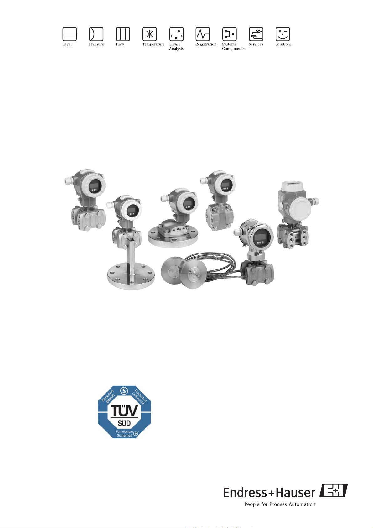
Deltabar S PMD70/75, FMD76/77/78
Differential pressure measurement
Differential pressure transmitter with ceramic and silicon sensors
Overload-resistant and function-monitored, Communication via
HART, PROFIBUS PA or FOUNDATION Fieldbus
Application
The Deltabar S differential pressure transmitter is used
for the following measuring tasks:
• Flow measurement (volume or mass flow) in
conjunction with primary elements in gases, vapours
and liquids
• Level, volume or mass measurement in liquids
• Differential pressure monitoring, e.g. of filters and
pumps
• International usage thanks to a wide range of approvals
Your benefits
• Very good reproducibility and long-term stability
• High reference accuracy: up to 0.075%,
as PLATINUM version: 0.05%
• Turn down 100:1, higher on request
• Used for flow and differential pressure monitoring
up to SIL 3, certified to IEC 61508 by TÜV SÜD
• HistoROM
• Function-monitored from the measuring cell to the
electronics
• Continuous modularity for differential pressure,
hydrostatic and pressure (Deltabar S, Deltapilot S,
Cerabar S), e.g.
– replaceable display
– universal electronics for pressure and
• Quick commissioning thanks to quick setup menu
• Easy and safe menu-guided operation on-site,
via 4...20 mA with HART, via PROFIBUS PA or
via FOUNDATION Fieldbus
• Extensive diagnostic functions
®
/M-DAT memory module
differential pressure
TI382P/00/EN/06.09
No. 71095431
Page 2

Table of contents
Deltabar S
Function and system design. . . . . . . . . . . . . . . . . . . . . 4
Device selection . . . . . . . . . . . . . . . . . . . . . . . . . . . . . . . . . . . . . . 4
Measuring principle . . . . . . . . . . . . . . . . . . . . . . . . . . . . . . . . . . . 5
Flow measurement . . . . . . . . . . . . . . . . . . . . . . . . . . . . . . . . . . . . 6
Level measurement (level, volume and mass) . . . . . . . . . . . . . . . . 7
Communication protocol . . . . . . . . . . . . . . . . . . . . . . . . . . . . . . . 7
Input . . . . . . . . . . . . . . . . . . . . . . . . . . . . . . . . . . . . . . 8
Measured variable . . . . . . . . . . . . . . . . . . . . . . . . . . . . . . . . . . . . 8
Measuring range . . . . . . . . . . . . . . . . . . . . . . . . . . . . . . . . . . . . . . 8
Explanation of terms . . . . . . . . . . . . . . . . . . . . . . . . . . . . . . . . . . . 9
Output . . . . . . . . . . . . . . . . . . . . . . . . . . . . . . . . . . . . 10
Output signal . . . . . . . . . . . . . . . . . . . . . . . . . . . . . . . . . . . . . . . 10
Signal range – 4...20 mA HART . . . . . . . . . . . . . . . . . . . . . . . . . 10
Signal on alarm . . . . . . . . . . . . . . . . . . . . . . . . . . . . . . . . . . . . . 10
Load – 4...20 mA HART . . . . . . . . . . . . . . . . . . . . . . . . . . . . . . . 10
Resolution . . . . . . . . . . . . . . . . . . . . . . . . . . . . . . . . . . . . . . . . . 10
Dynamic behavior current output . . . . . . . . . . . . . . . . . . . . . . . . 11
Dynamic behavior HART . . . . . . . . . . . . . . . . . . . . . . . . . . . . . . 11
Dynamic behavior PROFIBUS PA . . . . . . . . . . . . . . . . . . . . . . . . 12
Dynamic behavior FOUNDATION Fieldbus . . . . . . . . . . . . . . . . 12
Damping . . . . . . . . . . . . . . . . . . . . . . . . . . . . . . . . . . . . . . . . . . 13
Data of the FOUNDATION
Fieldbus interface . . . . . . . . . . . . . . . . . . . . . . . . . . . . . . . . . . . . 13
Warm-up period – PMD70, FMD76 . . . . . . . . . . . . . . . . . . . . . 22
Influence of the operating pressure on zero point and span – PMD70,
FMD76 . . . . . . . . . . . . . . . . . . . . . . . . . . . . . . . . . . . . . . . . . . . 22
Thermal change of the zero output and the output span – PMD70,
FMD76 . . . . . . . . . . . . . . . . . . . . . . . . . . . . . . . . . . . . . . . . . . . 22
Operating conditions (Installation) . . . . . . . . . . . . . . 23
General installation instructions . . . . . . . . . . . . . . . . . . . . . . . . . 23
Measuring arrangement . . . . . . . . . . . . . . . . . . . . . . . . . . . . . . . 23
Heat insulation – FMD77 . . . . . . . . . . . . . . . . . . . . . . . . . . . . . . 24
Wall- and pipe-mounting . . . . . . . . . . . . . . . . . . . . . . . . . . . . . . 24
"Separate housing" version . . . . . . . . . . . . . . . . . . . . . . . . . . . . . 25
Turn the housing . . . . . . . . . . . . . . . . . . . . . . . . . . . . . . . . . . . . 26
Oxygen applications . . . . . . . . . . . . . . . . . . . . . . . . . . . . . . . . . . 26
Ultra pure gas applications . . . . . . . . . . . . . . . . . . . . . . . . . . . . . 26
Process isolating diaphragms for materials with hydrogen build-up
(Gold-Rhodium coating) . . . . . . . . . . . . . . . . . . . . . . . . . . . . . . . 27
Operating conditions (Environment) . . . . . . . . . . . . . 27
Ambient temperature range . . . . . . . . . . . . . . . . . . . . . . . . . . . . 27
Storage temperature range . . . . . . . . . . . . . . . . . . . . . . . . . . . . . 27
Degree of protection . . . . . . . . . . . . . . . . . . . . . . . . . . . . . . . . . 27
Climate class . . . . . . . . . . . . . . . . . . . . . . . . . . . . . . . . . . . . . . . 27
Vibration resistance . . . . . . . . . . . . . . . . . . . . . . . . . . . . . . . . . . 27
Electromagnetic compatibility . . . . . . . . . . . . . . . . . . . . . . . . . . 27
Overvoltage protection (optional) . . . . . . . . . . . . . . . . . . . . . . . . 28
Power supply . . . . . . . . . . . . . . . . . . . . . . . . . . . . . . . 15
Electrical connection . . . . . . . . . . . . . . . . . . . . . . . . . . . . . . . . . 15
Supply voltage . . . . . . . . . . . . . . . . . . . . . . . . . . . . . . . . . . . . . . 18
Current consumption . . . . . . . . . . . . . . . . . . . . . . . . . . . . . . . . . 18
Cable entry . . . . . . . . . . . . . . . . . . . . . . . . . . . . . . . . . . . . . . . . 18
Cable specification . . . . . . . . . . . . . . . . . . . . . . . . . . . . . . . . . . . 18
Residual ripple . . . . . . . . . . . . . . . . . . . . . . . . . . . . . . . . . . . . . . 18
Influence of power supply . . . . . . . . . . . . . . . . . . . . . . . . . . . . . . 18
Performance characteristics – general . . . . . . . . . . . . 19
Reference operating conditions . . . . . . . . . . . . . . . . . . . . . . . . . . 19
Long-term stability . . . . . . . . . . . . . . . . . . . . . . . . . . . . . . . . . . . 19
Influence of the installation position . . . . . . . . . . . . . . . . . . . . . . 19
Vibration effects . . . . . . . . . . . . . . . . . . . . . . . . . . . . . . . . . . . . . 19
Performance characteristics – metallic process isolating
diaphragms . . . . . . . . . . . . . . . . . . . . . . . . . . . . . . . . 20
Reference accuracy – PMD75, FMD77, FMD78 . . . . . . . . . . . . . 20
Total performance – PMD75 . . . . . . . . . . . . . . . . . . . . . . . . . . . 20
Total Error . . . . . . . . . . . . . . . . . . . . . . . . . . . . . . . . . . . . . . . . 20
Warm-up period – PMD75, FMD77, FMD78 . . . . . . . . . . . . . . . 21
Influence of the operating pressure on zero point and span – PMD75,
FMD77, FMD78 . . . . . . . . . . . . . . . . . . . . . . . . . . . . . . . . . . . . 21
Thermal change of the zero output and the output
span -- PMD75 . . . . . . . . . . . . . . . . . . . . . . . . . . . . . . . . . . . . . 21
Performance characteristics – ceramic process isolating
diaphragms . . . . . . . . . . . . . . . . . . . . . . . . . . . . . . . . 22
Reference accuracy – PMD70, FMD76 . . . . . . . . . . . . . . . . . . . 22
Total performance – PMD70, FMD76 . . . . . . . . . . . . . . . . . . . . 22
Total Error . . . . . . . . . . . . . . . . . . . . . . . . . . . . . . . . . . . . . . . . 22
Operating conditions (Process) . . . . . . . . . . . . . . . . . 28
Process temperature limits . . . . . . . . . . . . . . . . . . . . . . . . . . . . . 28
Process temperature range, seals . . . . . . . . . . . . . . . . . . . . . . . . 28
Pressure specifications . . . . . . . . . . . . . . . . . . . . . . . . . . . . . . . . 29
Mechanical construction . . . . . . . . . . . . . . . . . . . . . . 30
Housing dimensions T14, optional display on the side . . . . . . . . . 30
Housing dimensions T15, optional display on the top . . . . . . . . . 30
Housing dimensions T17, optional display on the top . . . . . . . . . 30
Process connections PMD70 with ceramic process isolating
diaphragms . . . . . . . . . . . . . . . . . . . . . . . . . . . . . . . . . . . . . . . . 31
Process connections PMD70 with ceramic process isolating
(continued) . . . . . . . . . . . . . . . . . . . . . . . . . . . . . . . . . . . . . . . . 32
Process connections PMD75 with metallic process isolating
diaphragms . . . . . . . . . . . . . . . . . . . . . . . . . . . . . . . . . . . . . . . . 33
Process connections PMD75 with metallic process isolating
diaphragms (continued) . . . . . . . . . . . . . . . . . . . . . . . . . . . . . . . 34
Process connections PMD75 with metallic process isolating
diaphragms (continued) . . . . . . . . . . . . . . . . . . . . . . . . . . . . . . . 35
Process connection FMD76 with ceramic process isolating
diaphragms . . . . . . . . . . . . . . . . . . . . . . . . . . . . . . . . . . . . . . . . 36
Process connection FMD76 with ceramic process isolating
diaphragms (continued) . . . . . . . . . . . . . . . . . . . . . . . . . . . . . . . 37
Process connection FMD76 with ceramic process isolating
diaphragms (continued) . . . . . . . . . . . . . . . . . . . . . . . . . . . . . . . 38
Process connections FMD77 with metallic process isolating
diaphragms, low-pressure side . . . . . . . . . . . . . . . . . . . . . . . . . . 38
Process connections FMD77 with metallic process isolating
diaphragms, high-pressure side . . . . . . . . . . . . . . . . . . . . . . . . . . 39
Process connections FMD77 with metallic process isolating
diaphragms, high-pressure side (continued) . . . . . . . . . . . . . . . . 40
2 Endress+Hauser
Page 3

Deltabar S
Process connections FMD77 with metallic process isolating
diaphragms, high-pressure side (continued) . . . . . . . . . . . . . . . . 41
FMD78 Basic unit . . . . . . . . . . . . . . . . . . . . . . . . . . . . . . . . . . . 42
Process connection FMD78 with metallic process isolating
diaphragm . . . . . . . . . . . . . . . . . . . . . . . . . . . . . . . . . . . . . . . . . 43
Process connection FMD78 with metallic process isolating
diaphragm (continued) . . . . . . . . . . . . . . . . . . . . . . . . . . . . . . . . 44
Process connection FMD78 with metallic measuring
diaphragms (continued) . . . . . . . . . . . . . . . . . . . . . . . . . . . . . . . 45
Process connection FMD78 with metallic measuring
diaphragms (continued) . . . . . . . . . . . . . . . . . . . . . . . . . . . . . . . 46
Process connection FMD78 with metallic measuring
diaphragms (continued) . . . . . . . . . . . . . . . . . . . . . . . . . . . . . . . 47
Process connection FMD78 with metallic measuring
diaphragms (continued) . . . . . . . . . . . . . . . . . . . . . . . . . . . . . . . 48
Process connection FMD78 with metallic measuring
diaphragms (continued) . . . . . . . . . . . . . . . . . . . . . . . . . . . . . . . 49
"Separate housing" version . . . . . . . . . . . . . . . . . . . . . . . . . . . . . 50
Weight . . . . . . . . . . . . . . . . . . . . . . . . . . . . . . . . . . . . . . . . . . . 51
Material . . . . . . . . . . . . . . . . . . . . . . . . . . . . . . . . . . . . . . . . . . . 51
Human interface . . . . . . . . . . . . . . . . . . . . . . . . . . . . 53
Operating elements . . . . . . . . . . . . . . . . . . . . . . . . . . . . . . . . . . 53
Local operation . . . . . . . . . . . . . . . . . . . . . . . . . . . . . . . . . . . . . 55
Remote operation . . . . . . . . . . . . . . . . . . . . . . . . . . . . . . . . . . . 55
Hard- und Software for on-site and remote operation . . . . . . . . . 56
FMD78 (continued) . . . . . . . . . . . . . . . . . . . . . . . . . . . . . . . . . 81
Additional documentation . . . . . . . . . . . . . . . . . . . . . 82
Field of Activities . . . . . . . . . . . . . . . . . . . . . . . . . . . . . . . . . . . . 82
Technical Information . . . . . . . . . . . . . . . . . . . . . . . . . . . . . . . . 82
Operating Instructions . . . . . . . . . . . . . . . . . . . . . . . . . . . . . . . . 82
Brief operating instructions . . . . . . . . . . . . . . . . . . . . . . . . . . . . 82
Manual for Functional Safety (SIL) . . . . . . . . . . . . . . . . . . . . . . . 82
Safety Instructions . . . . . . . . . . . . . . . . . . . . . . . . . . . . . . . . . . . 82
Installation/Control Drawings . . . . . . . . . . . . . . . . . . . . . . . . . . 83
Overspill protection . . . . . . . . . . . . . . . . . . . . . . . . . . . . . . . . . . 84
Planning instructions, diaphragm seal systems . . . . . 58
Applications . . . . . . . . . . . . . . . . . . . . . . . . . . . . . . . . . . . . . . . . 58
Design and operation mode . . . . . . . . . . . . . . . . . . . . . . . . . . . . 58
Diaphragm seal filling oils . . . . . . . . . . . . . . . . . . . . . . . . . . . . . 59
Influence of the temperature on the zero point . . . . . . . . . . . . . . 60
Ambient temperature range . . . . . . . . . . . . . . . . . . . . . . . . . . . . 62
Response time . . . . . . . . . . . . . . . . . . . . . . . . . . . . . . . . . . . . . . 62
Installation instructions . . . . . . . . . . . . . . . . . . . . . . . . . . . . . . . 64
Certificates and approvals . . . . . . . . . . . . . . . . . . . . . 66
CE mark . . . . . . . . . . . . . . . . . . . . . . . . . . . . . . . . . . . . . . . . . . 66
Ex approvals . . . . . . . . . . . . . . . . . . . . . . . . . . . . . . . . . . . . . . . 66
Marine certificate . . . . . . . . . . . . . . . . . . . . . . . . . . . . . . . . . . . . 66
Functional Safety SIL / IEC 61508 Declaration of conformity
(optional) . . . . . . . . . . . . . . . . . . . . . . . . . . . . . . . . . . . . . . . . . . 66
Overspill protection . . . . . . . . . . . . . . . . . . . . . . . . . . . . . . . . . . 66
CRN approvals . . . . . . . . . . . . . . . . . . . . . . . . . . . . . . . . . . . . . . 66
Pressure Equipment Directive (PED) . . . . . . . . . . . . . . . . . . . . . 66
Standards and guidelines . . . . . . . . . . . . . . . . . . . . . . . . . . . . . . 66
Ordering information . . . . . . . . . . . . . . . . . . . . . . . . 67
PMD70 . . . . . . . . . . . . . . . . . . . . . . . . . . . . . . . . . . . . . . . . . . . 67
PMD70 (continued) . . . . . . . . . . . . . . . . . . . . . . . . . . . . . . . . . . 68
PMD70 (continued) . . . . . . . . . . . . . . . . . . . . . . . . . . . . . . . . . . 69
PMD75 . . . . . . . . . . . . . . . . . . . . . . . . . . . . . . . . . . . . . . . . . . . 70
PMD75 (continued) . . . . . . . . . . . . . . . . . . . . . . . . . . . . . . . . . . 71
PMD75 (continued) . . . . . . . . . . . . . . . . . . . . . . . . . . . . . . . . . . 72
FMD76 . . . . . . . . . . . . . . . . . . . . . . . . . . . . . . . . . . . . . . . . . . . 73
FMD76 (continued) . . . . . . . . . . . . . . . . . . . . . . . . . . . . . . . . . . 74
FMD76 (continued) . . . . . . . . . . . . . . . . . . . . . . . . . . . . . . . . . . 75
FMD77 . . . . . . . . . . . . . . . . . . . . . . . . . . . . . . . . . . . . . . . . . . . 76
FMD77 (continued) . . . . . . . . . . . . . . . . . . . . . . . . . . . . . . . . . . 77
FMD77 (continued) . . . . . . . . . . . . . . . . . . . . . . . . . . . . . . . . . . 78
FMD78 . . . . . . . . . . . . . . . . . . . . . . . . . . . . . . . . . . . . . . . . . . . 79
FMD78 (continued) . . . . . . . . . . . . . . . . . . . . . . . . . . . . . . . . . . 80
3 Endress+Hauser
Page 4
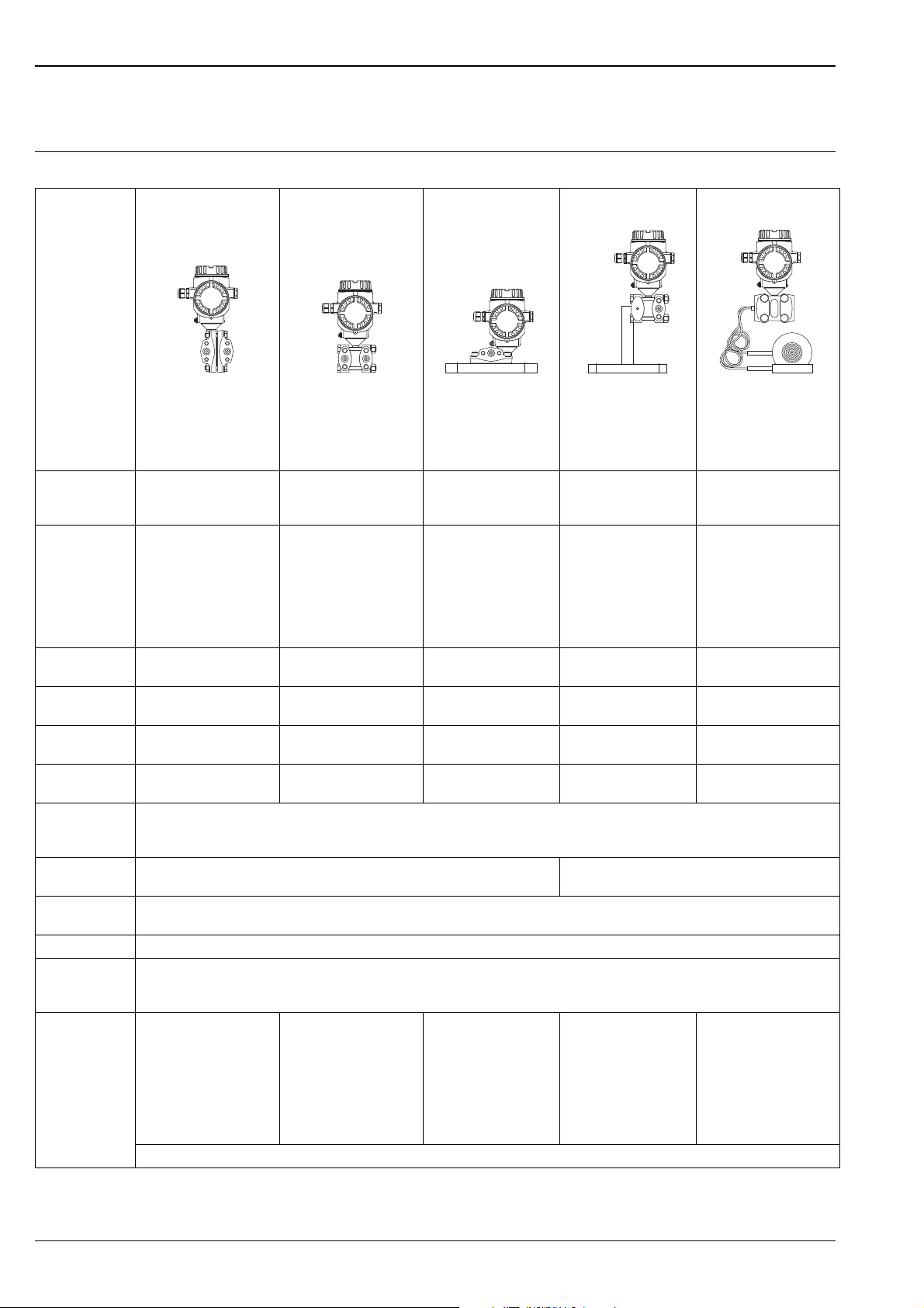
Device selection
+ –
+ –
Deltabar S
Function and system design
Deltabar S –
PMD70
PMD75
FMD76
product family
Field of
application
Process
connections
P01-PMD70xxx-16-xx-xx-xx-000
With ceramic process
isolating diaphragms
–Flow
– Level
– Differential pressure
– 1/4 – 18 NPT
–RC 1/4
P01-PMD75xxx-16-xx-xx-xx-000
With metallic process
isolating diaphragms
–Flow
– Level
– Differential pressure
–1/4 – 18 NPT
–RC 1/4
P01-FMD76xxx-16-xx-xx-xx-000
With ceramic process
isolating diaphragms
– Level – Level – Level
Low-pressure side (–):
– 1/4 – 18 NPT
–RC 1/4
High-pressure side (+):
– DN 80 – DN 100
– ANSI 3" – 4"
– JIS 80A – 100A
Measuring ranges from –25...+25 mbar
to –3...+3 bar
Overload
1
on one side: max. 100 bar
on both sides: max. 150 bar
Process
temperature range
Ambient
temperature range
–20...+85°C
(–4...+185°F)
–20...+85°C
(–4...+185°F)
Ambient
from –10...+10 mbar
to –40...+40 bar
on one side: max. 420 bar
on both sides: max. 630 bar
–40...+120°C
(–40...+248°F)
–40...+85°C
(–40...+185°F)
2
from –100...+100 mbar
to –3...+3 bar
on one side: max. 100 bar on one side: max. 160 bar on one side: max. 160 bar
–20...+85°C
(–4...+185°F)
–20...+85°C
(–4...+185°F)
–40 to +60°C (–40 to +140°F)
temperature range
separate housing
Reference
Accuracy
–Up to 0.075% of the set span
–PLATINUM version: up to 0.05% of the set span
Supply voltage – For non-hazardous areas: 10.5...45 V DC
– Ex ia: 10.5...30 V DC
Output 4...20 mA with superimposed HART protocol, PROFIBUS PA or FOUNDATION Fieldbus
Options – High-pressure version up to p
– PMD75, FMD77, FMD78: Gold-Rhodium-coated process isolating diaphragm, NACE-compliant materials
700 bar
stat
– Separate housing
Specialities
(options)
– Metal-free measurement
with PVDF flange
– Available with Deltatop
as flow compact device
–p
up to 420 bar
stat
– Process isolating
diaphragm: tantalum
– Available with Deltatop
as flow compact device
– Abrasion-resistant and
corrosion-resistant
– No diaphragm-seal
temperature effects
– Metal-free
measurement possible
with ECTFE-coated
process connection
–HistoROM
®
/M-DAT memory module
FMD77
P01-FMD77xxx-16-xx-xx-xx-000
With metallic process
isolating diaphragms
and diaphragm seal
mounted on one side
FMD78
P01-FMD78xxx-16-xx-xx-xx-003
With metallic process
isolating diaphragms and
capillary diaphragm
seals
– Differential pressure
Low-pressure side (–):
– 1/4 – 18 NPT
– Wide range of
diaphragm seals
–RC 1/4
High-pressure side (+):
–DN 50 – DN 100
–ANSI 2" – 4"
– JIS 80A – 100A
from –100...+100 mbar
to –16 bar...+16 bar
from –100...+100 mbar
to –40...+40 bar
on both sides: max. 240 bar
up to + 400°C (+752°F) up to +400°C (+752°F)
–40...+85°C
(–40...+185°F)
2
–40...+85°C
(–40...+185°F)
2
–Up to 0.075 % of the set span
–For high media
temperatures
– Wide range of
diaphragm seals
1) dependent on the lowest-rated element, with regard to pressure, of the selected components
2) lower temperature on request
4 Endress+Hauser
Page 5
Deltabar S
➀
➁
➃
➂
➄
1
p
2
p
➂
➃
➄
➀
➁
1
p
2
p
1
p
2
p
➆
➇
➈
➅
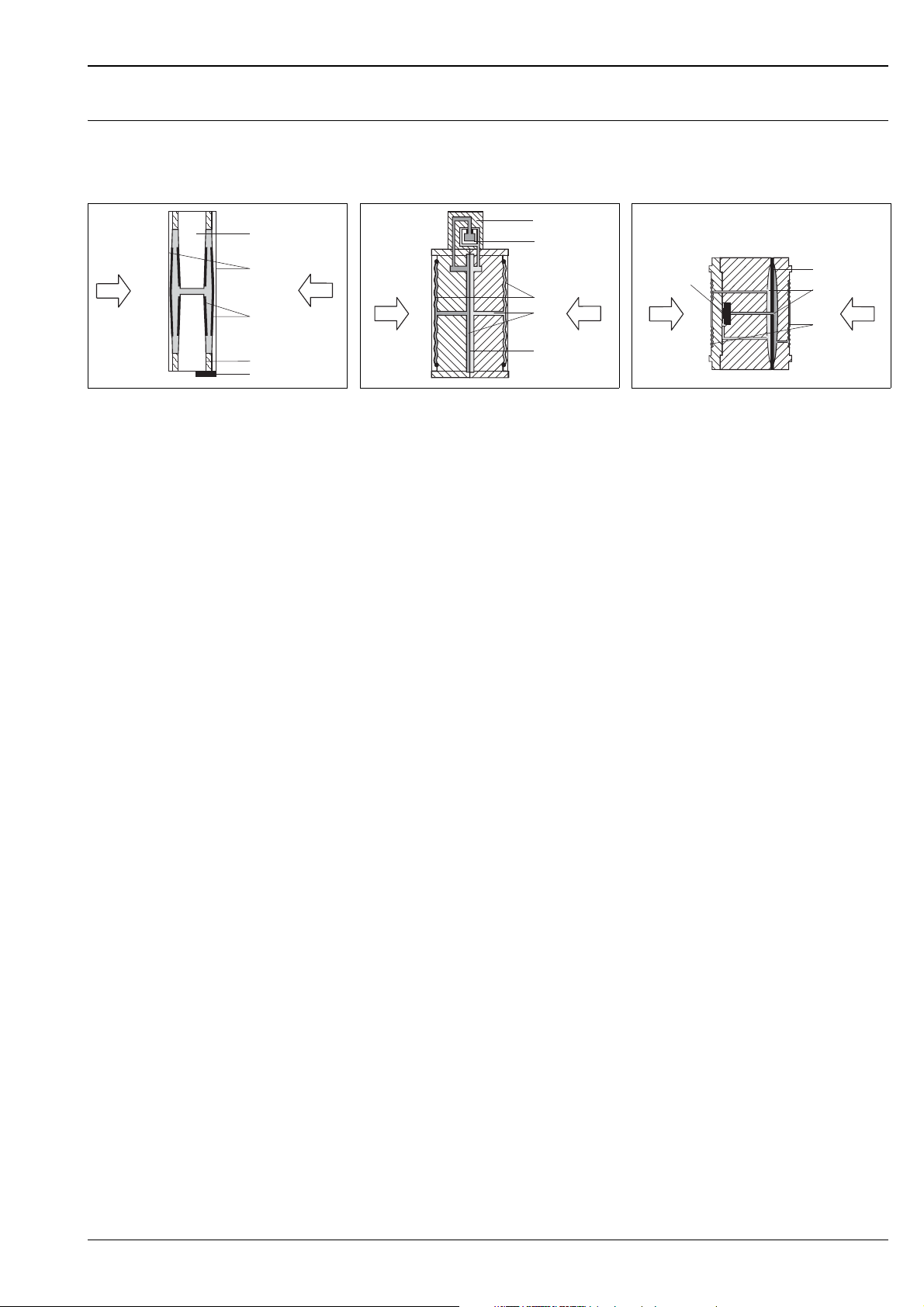
Measuring principle
Ceramic process isolating diaphragms used for PMD70 and FMD76
P01-xMD7xxxx-03-xx-xx-xx-000
Ceramic measuring cell PMD70 and FMD76
1 Meter body
2 Process isolating diaphragm
3 Electrodes
4 Glass frit fixes the process isolating
diaphragm onto the meter body
5 Temperature sensor
Ceramic process isolating diaphragms used for PMD70 and FMD76
The ceramic measuring cell is based on the principle of a plate capacitor with an electrode on (1) and a movable
electrode on the interior of the diaphragm (3). Standard silicone oil or mineral oil filling oils for this measuring
cell.
A differential pressure (p
are converted and are fed to the microprocessor of the transmitter as a digital signal.
Advantages:
• Self-monitoring for process isolating diaphragm break or oil loss (constant comparison of the measured
temperature with a temperature calculated from the capacitance values)
• Extremely high resistance to aggressive media
• Suitable for vacuums up to 1 mbar
• Metal-free versions available
• Second process barrier (Secondary Containment) for enhanced integrity
Metallic process isolating diaphragms used for PMD75, FMD77 and FMD78
P01-xMD7xxxx-03-xx-xx-xx-002
Metal measuring cell 10 mbar and 30 mbar
1 Sensing element
2 Silicon diaphragm
3 Process isolating diaphragm
4 Filling oil
5 Overload diaphragm
p2) causes a corresponding deflection of both diaphragms. Both capacitance values
1
abs
Metal measuring cell as of 100 mbar
6 Sensing element
7 Overload diaphragm
8 Filling oil
9 Process isolating diaphragm
P01-xMD7xxxx-03-xx-xx-xx-003
Metallic process isolating diaphragms used for PMD75, FMD77 and FMD78
The process isolating diaphragms (3/9) are deflected on both sides by the acting pressures. A filling oil (4/8)
transfers the pressure to a resistance circuit bridge (semi-conductor technology). The differential-pressuredependent change of the bridge output voltage is measured and further processed.
Advantages:
• Standard operating pressures: 160 bar and 420 bar
• High long-term stability
• Very high single-sided overload resistance
• Second process barrier (Secondary Containment) for enhanced integrity
Endress+Hauser 5
Page 6
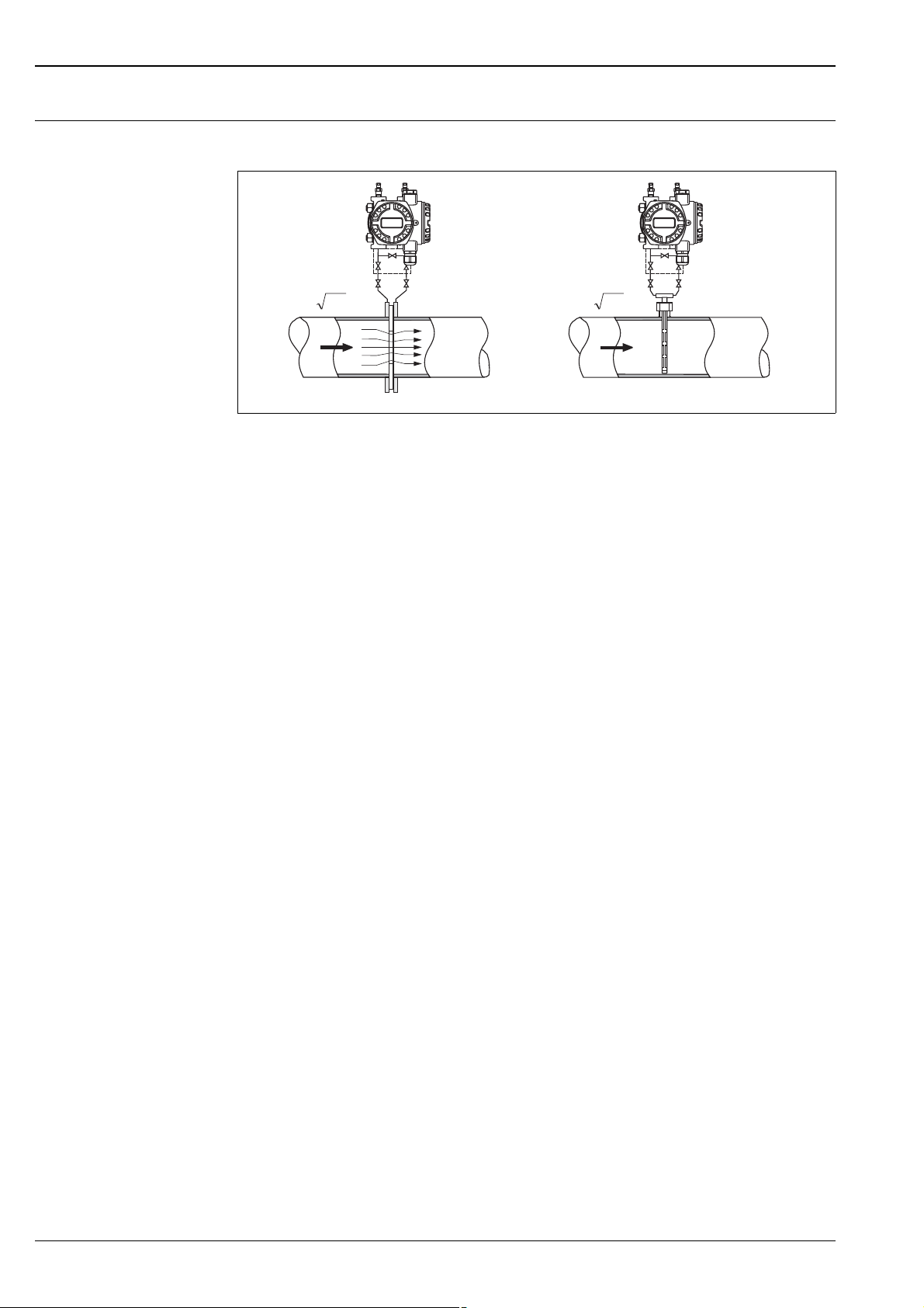
Flow measurement Design and operation mode
QQ
p
1
p
1
p
2
p
2
Q~
Δp
Q~
Δp
++
––
Flow measurement with Deltabar S and primary element, left: Orifice plate and right: Pitot tube
QFlow
p Differential pressure, p = p
1
– p
Deltabar S
P01-PMD7xxxx-15-xx-xx-xx-000
2
Your benefits
• Choice of four flow modes of operation: volume flow, norm volume flow (European norm conditions),
standard volume flow (American standard conditions) and mass flow.
• Choice of diverse flow units with automatic unit conversion.
• A customised unit can be specified
• Low flow cut off: when activated, this function suppresses small flows which can lead to large fluctuations
in the measured value.
• Contains two totalizers as standard. One totalizer can be reset to zero.
• The totalizing mode and unit can be individually set for each totalizer. This allows independent daily and
annual quantity totalizing.
• With the product family Deltatop, Endress+Hauser is offering a universal and reliable solutions for flow
measurement:
– Deltatop, the compact, ready-to-use flow measuring unit including differential pressure transmitter
Deltabar S
Note!
For more information about flow measurement with the Deltabar S differential pressure transmitter
• Deltabar S with orifice plate (TI422P, Deltatop DO6x)
• Deltabar S with pitot tube (TI425P, Deltatop DP6x)
6 Endress+Hauser
Page 7
Deltabar S
h=
Δp
ρ g
+
+
–
–
h
➀
➂
➁
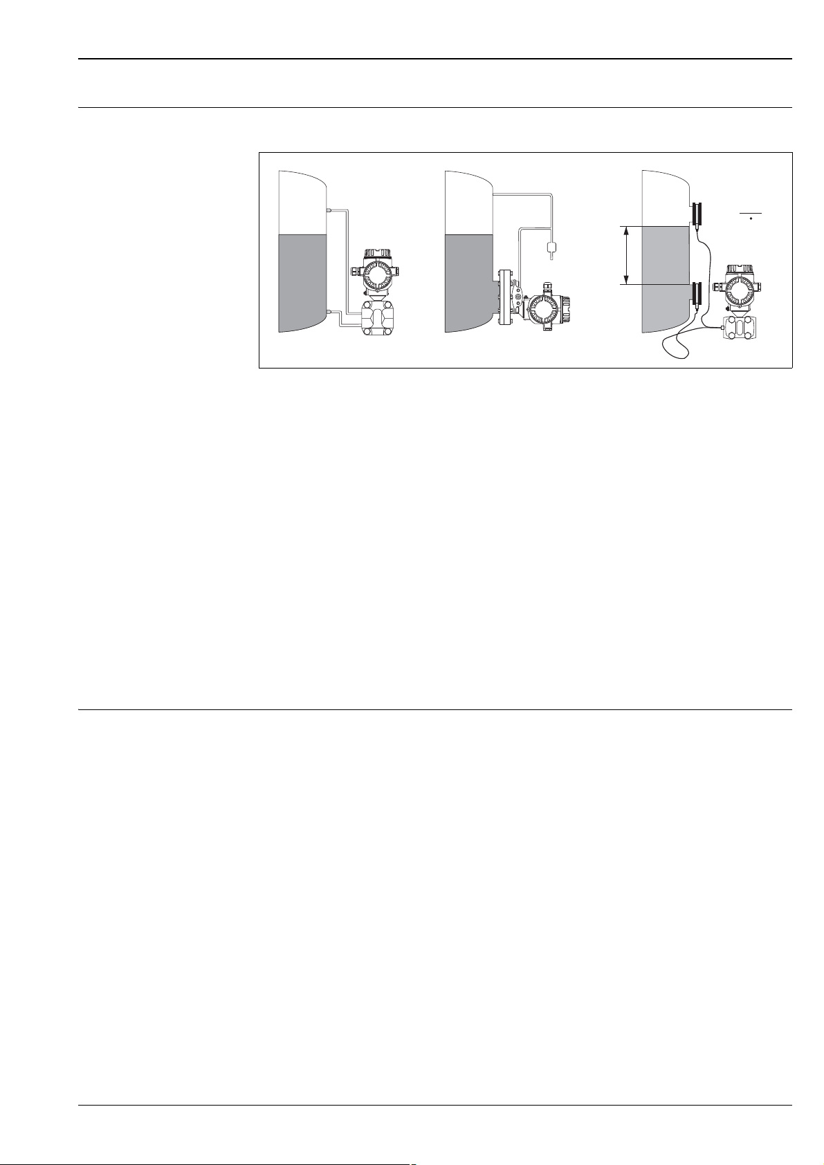
Level measurement (level, volume and mass)
Design and operation mode
P01xMD7xxxx-15-xx-xx-xx-000
Level measurement with Deltabar S
1 Level measurement via impulse piping and PMD70
2 Level measurement with FMD76
3 Level measurement with FMD78
h Height (level)
p Differential pressure
Density of the medium
g Gravitation constant
Your benefits
• Choice of three level operating modes
• Volume and mass measurements in any tank shapes by means of a freely programmable characteristic curve
• Choice of diverse level units with automatic unit conversion
• A customised unit can be specified
• Has a wide range of uses, e.g.
– for level measurement in tanks with superimposed pressure
– in the event of foam formation
– in tanks with agitators of screen fittings
– in the event of liquid gases
– for standard level measurement
Communication protocol • 4...20 mA with HART communication protocol
• PROFIBUS PA
– The Endress+Hauser devices meet the requirements as per the FISCO model.
– Due to the low current consumption of 13 mA ± 1 mA
– up to 7 Deltabar S for Ex ia, CSA IS and FM IS applications
– up to 27 Deltabar S for all other applications, e.g. in non-hazardous areas, Ex nA, etc.
can be operated at one bus segment with installation as per FISCO.
Further information on PROFIBUS PA, such as requirements for bus system components, can be found in
the Operating Instructions BA034S "PROFIBUS DP/PA: Guidelines for planning and commissioning" and in
the PNO guideline.
• FOUNDATION Fieldbus
– The Endress+Hauser devices meet the requirements as per the FISCO model.
– Due to the low current consumption of 15 mA ± 1 mA
– up to 6 Deltabar S for Ex ia, CSA IS and FM IS applications
– up to 24 Deltabar S for all other applications, e.g. in non-hazardous areas, Ex nA, etc.
can be operated at one bus segment with installation as per FISCO.
Further information on FOUNDATION Fieldbus, such as requirements for bus system components can be
found in the Operating Instructions BA013S "FOUNDATION Fieldbus Overview".
Endress+Hauser 7
Page 8
Deltabar S
Input
Measured variable Differential pressure, from which flow (volume or mass current) and level (level, volume or mass) are derived
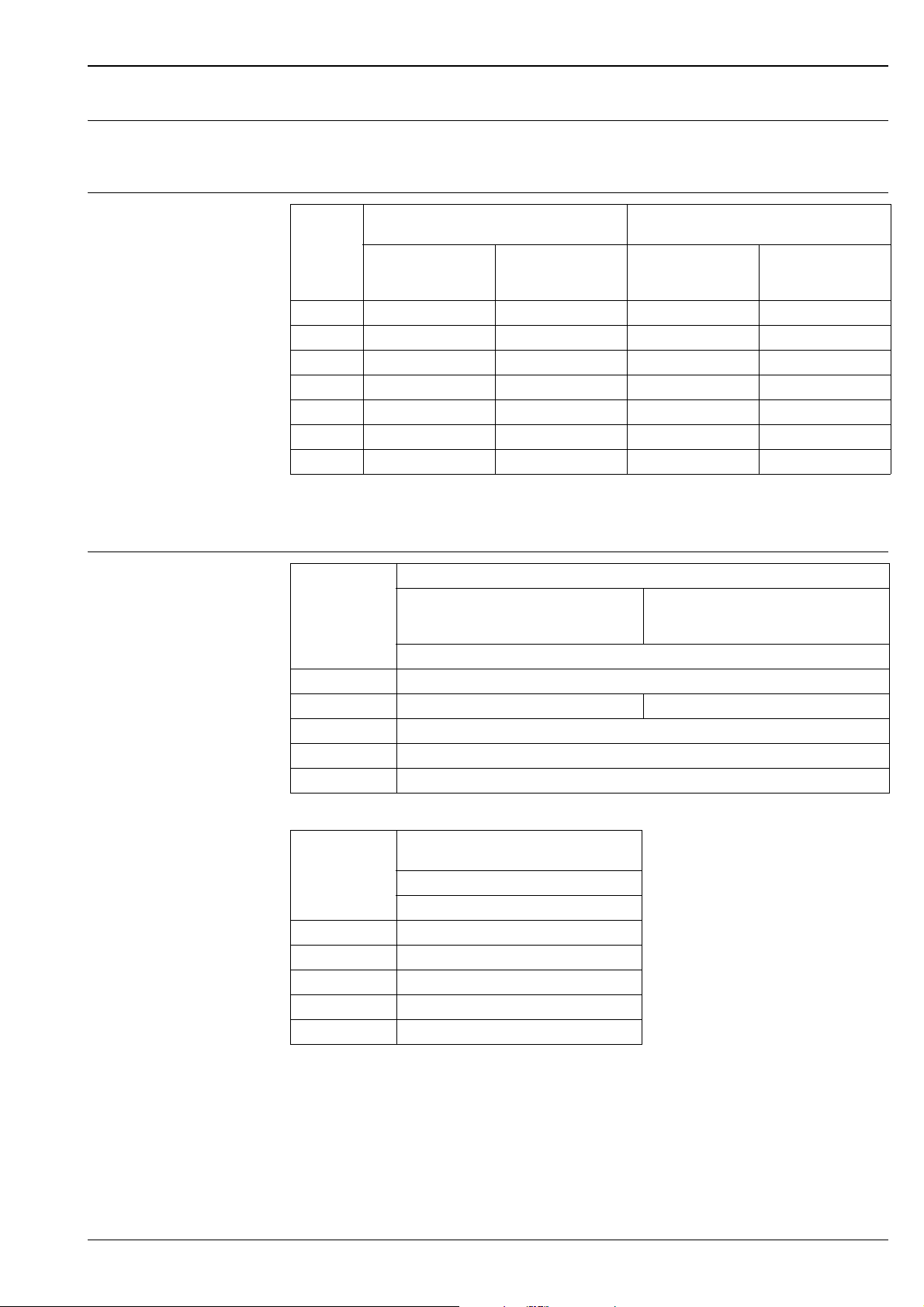
Measuring range PMD75, FMD77, FMD78 (with metallic process isolating diaphragms)
Nominal
value
Measurement
limit
lower
(LRL)
upper
(URL)
Smallest
calibratable
5
span
MWP
1
Overload
on one side on both sides PN 160 6PN 420
[mbar] [mbar] [mbar] [mbar] [bar] [bar] [bar] [mbar
7
10
7
30
100 –100 +100 1/5
500 –500 +500 5 160/420
–10 +10 0.25 160 160 240 0.1 7B –
–30 +30 0.3 160 160 240 0.1 7C –
8
160 160 240 0.1 7D –
9
160/420 240/630 0.1 7F 8F
2
Min. operating pressure
3
Versions in the
order code
]
abs
3000 –3000 +3000 30 160/420 9160/420 240/630 0.1 7H 8H
16000 –16000 +16000 160 160/420
40000 –40000 +40000 400 160/420
9
160/420 240/630 0.1 7L 8L
9
"+"side:
160/420
240/630 0.1 7M 8M
10
PMD70, FMD76 (with ceramic process isolating diaphragms)
Nominal
value
Measurement
limit
lower
(LRL)
upper
(URL)
Smallest
calibratable
5
span
MWP
1
Overload
on one side on both sides
[mbar] [mbar] [mbar] [mbar] [bar] [bar] [bar] [mbar
25 –25 +25 0.25 10 10 15 1 7B
100 –100 +100 1 16 16 24 1 7D
500 –500 +500 5 100 100 150 1 7F
3000 –3000 +3000 30 100 100 150 1 7H
2
Min. operating pressure 3Versions in the
order code
]
abs
4
4
6
1) The MWP (maximum working pressure; MWP = PN) for the measuring device depends on the weakest element of the components selected with regard to
pressure, i.e. the process connection ( ä 30 ff) has to be taken into consideration in addition to the measuring cell ( see table above). Also observe
pressure-temperature dependency. For the appropriate standards and further information, see ä 29, "Pressure specifications" section.
2) The maximum pressure for the measuring device is dependent on the lowest-rated element, with regard to pressure, of the selected components. See also
ä 29, section "Pressure specifications".
3) The minimum operating pressure indicated in the table applies to silicone oil under reference operating conditions.
Min. operating pressure at 85°C (185°F) for silicone oil: 10 mbar
FMD77 and FMD78: Min. operating pressure: 50 mbar
For vacuum applications, please observe the installation instructions on ä 65 ff.
; observe also the pressure and temperature application limits of the selected filling oil on ä 59.
abs
.
abs
4) Versions in the order code ä 71 ff, feature 40 "Nominal range; PN"
5) Turn down > 100:1 on request
6) PN 160 versions with stainless steel A2 screws, PN 420 versions with stainless steel A4 M12 screws
PN 420 versions for PMD75 only.
7) PMD75 only
8) minimum span that can be calibrated for PMD75: 1 mbar; minimum span that can be calibrated for FMD77 and FMD78: 5 mbar
9) For PMD75 with CRN-approved process connections, the MWP is 315 bar.
10) "–" side: 100 bar
8 Endress+Hauser
Page 9
Deltabar S
–500 mbar
0
+500 mbar
100
LRL
LRV
URL
URV
➁➀
=
➂
➃
➄
–500 mbar
+500 mbar
LRV
URLURV
➂
0
LRL
–300 mbar
➁➀
=
➃
➄
Explanation of terms
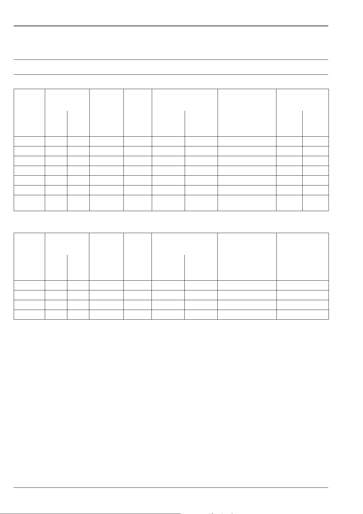
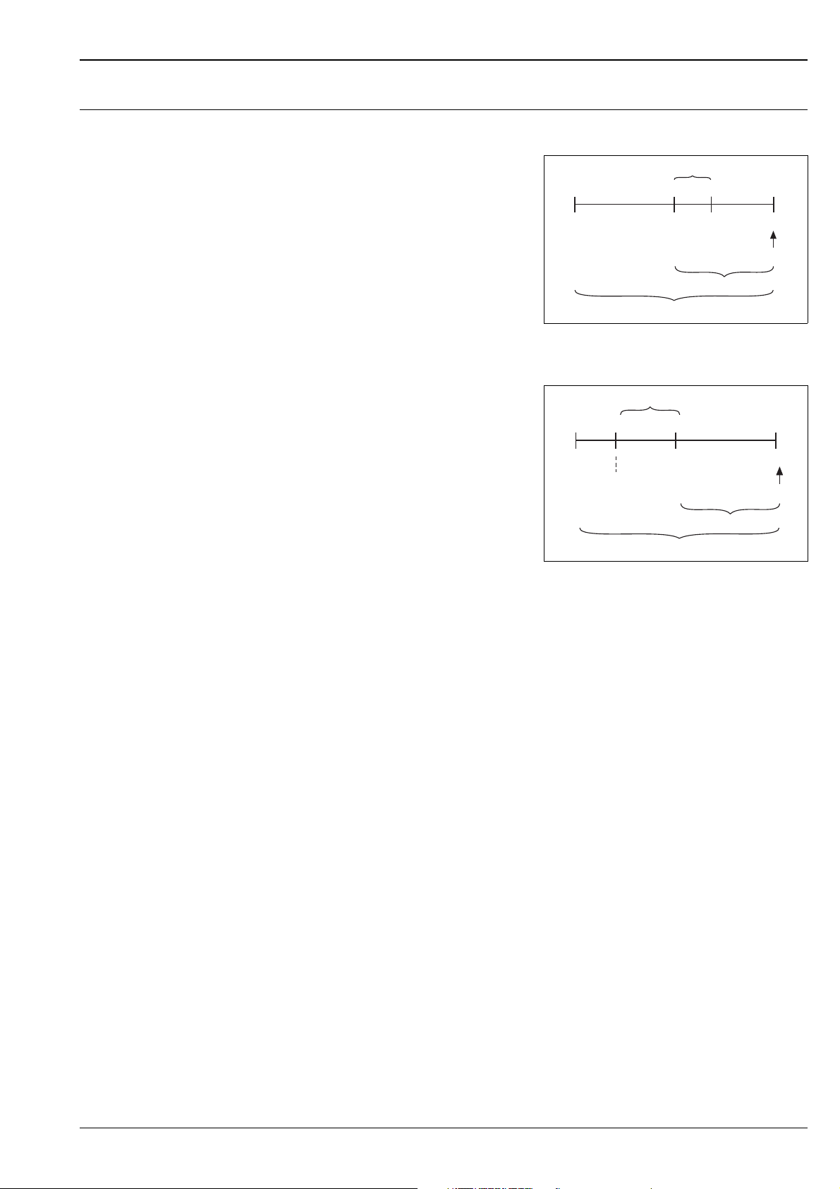
Explanation of the terms: Turn down (TD), set span and zero based span
Case 1:
• Lower range value Upper range value
Example:
• Lower range value (LRV) = 0 mbar
• Upper range value (URV) = 100 mbar
• Nominal value (URL) = 500 mbar
Turn down:
•TD = URL /URV:1
set span:
• URV – LRV = 100 mbar
This span is based on the zero point.
P01-xxxxxxxx-05-xx-xx-xx-001
Example: 500 mbar sensor
Case 2:
• Lower range value Upper range value
Example:
• Lower range value (LRV) = –300 mbar
• Upper range value (URV) = 0 bar
• Nominal value (URL) = 500 mbar
Turn down:
•TD = URL / (LRV) = 1.67:1
set span:
• URV – LRV = 300 mbar
This span is based on the zero point.
P01-xMD7xxxx-05-xx-xx-xx-007
Example: 500 mbar sensor
1 Set span
2 Zero based span
3 Nominal value i Upper range limit (URL)
4 Nominal measuring range
5 Sensor measuring range
LRL Lower range limit
URL Upper range limit
LRV Lower range value
URV Upper range value
Endress+Hauser 9
Page 10
Output
U – 10.5 V
R
L
max
23 mA
≤
30
20
10.5
U
[V]
40 45
1282
1500
847
413
[]Ω
R
L
max
30
20
11.5
U
[V]
40 45
1239
1456
804
369
[]Ω
R
L
max
TestTest
➀
➁
U – 11.5 V
R
L
max
23 mA
≤
➂
➃
➂
➃
Output signal • 4...20 mA with superimposed digital communication protocol HART 5.0, 2-wire
• Digital communication signal PROFIBUS PA (Profile 3.0)
– signal coding: Manchester Bus Powered (MBP); Manchester II
– data transmission rate: 31.25 KBit/s, voltage mode
• Digital communication signal FOUNDATION Fieldbus
– signal coding: Manchester Bus Powered (MBP); Manchester II
– data transmission rate: 31.25 KBit/s, voltage mode
Deltabar S
Signal range –
3.8 mA to 20.5 mA
4...20 mA HART
Signal on alarm As per NAMUR NE 43
• 4...20 mA HART
Options:
– Max. alarm*: can be set from 21...23 mA
– Keep measured value: last measured value is kept
– Min. alarm: 3.6 mA
* Factory setting: 22 mA
• PROFIBUS PA: can be set in the Analog Input block,
options: Last Valid Out Value, Fsafe Value (factory setting), Status bad
• FOUNDATION Fieldbus: can be set in the Analog Input Block,
options: Last Good Value, Fail Safe Value (factory setting), Wrong Value
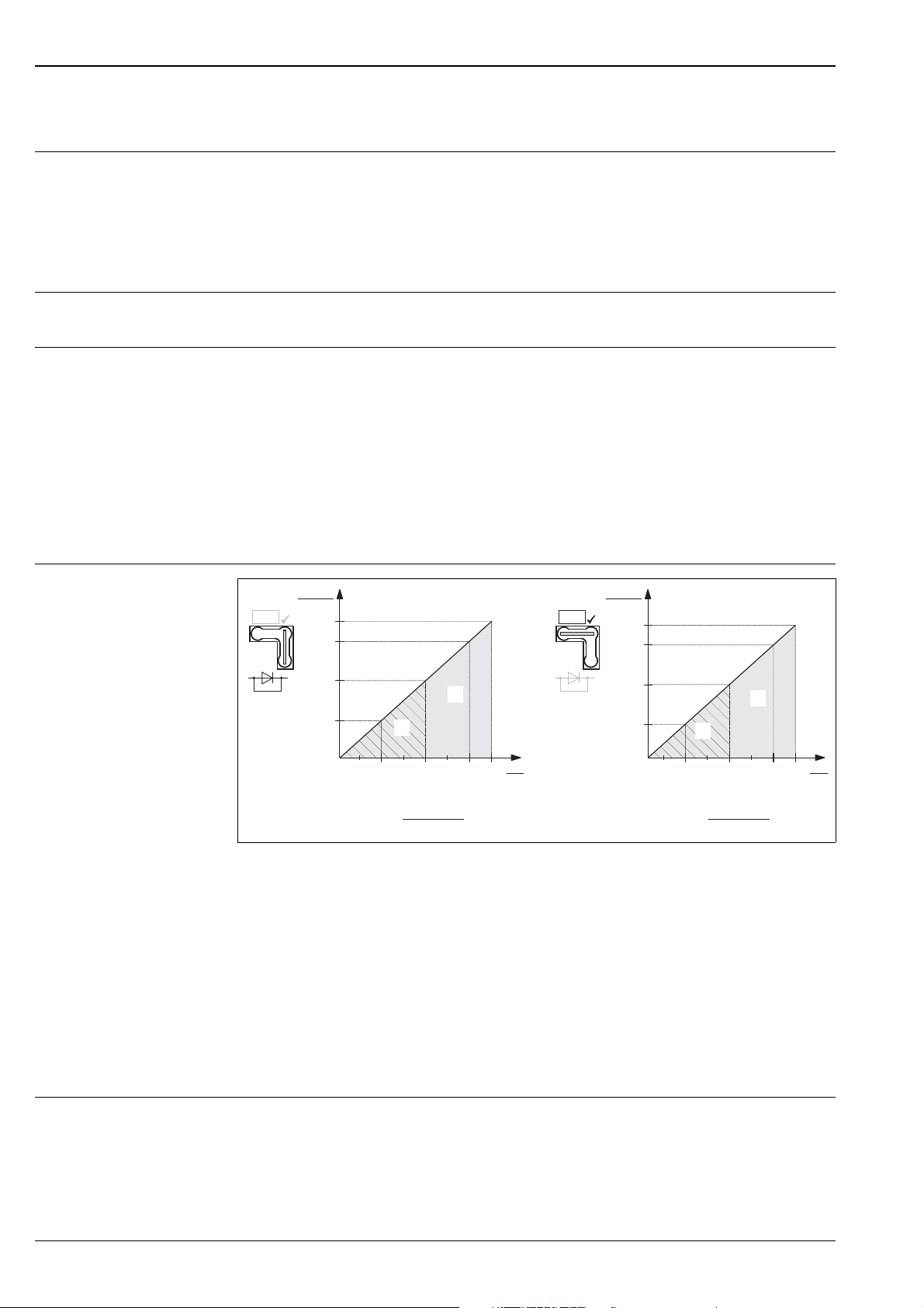
Load – 4...20 mA HART
P01-xMD7xxxx-05-xx-xx-xx-000
Load diagram, observe the position of the jumper and the explosion protection ( ä 17, section "Taking 4...20 mA test
signal".)
1 Jumper for 4...20 mA test signal inserted in "Non-test" position
2 Jumper for 4...20 mA test signal inserted in "Test" position
3 Supply voltage 10.5 (11.5)...30 V DC for 1/2 D, 1 GD, 1/2 GD, FM IS, CSA IS, IECEx ia, NEPSI Ex ia
4 Supply voltage 10.5 (11.5)...45 V DC for device for non-hazardous areas, 1/2 D, 1/3 D, 2 G Ex d, 3 G Ex nA, FM
XP, FM DIP, FM NI, CSA XP, CSA Dust-Ex, NEPSI Ex d
R
Maximum load resistance
Lmax
U Supply voltage
Note!
Resolution • Current output: 1 A
When operating via a handheld terminal or via PC with an operating program, a minimum communication
resistance of 250 must exist within the loop.
• Display: can be set (factory setting: presentation of the maximum accuracy of the transmitter)
10 Endress+Hauser
Page 11
Deltabar S
I
63 %
100 %
t
t1t
2
90 %
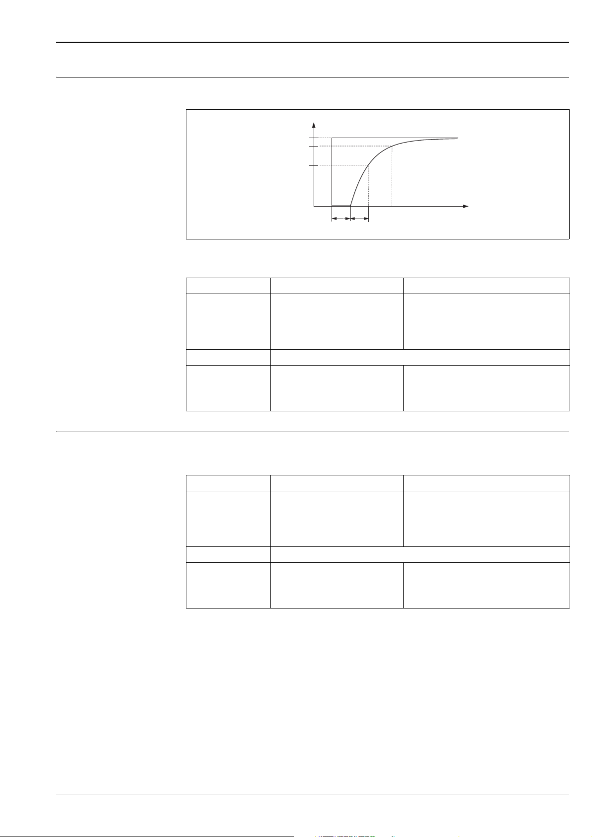
Dynamic behavior
current output
Dead time, Time constant (T63)
P01-xxxxxxxx-05-xx-xx-xx-007
Presentation of the dead time and the time constant
Type Dead time t
PMD75 45 ms • 10 mbar and 30 mbar measuring cell: 200 ms
FMD77, FMD78 dependent on the diaphragm seal
PMD70, FMD76 90 ms • 25 mbar measuring cell: 4700 ms
1
Time constant (T63), t
• 100 mbar measuring cell: 60 ms
• 500 mbar measuring cell: 45 ms
• 3 bar measuring cell: 40 ms
• 16 bar and 40 bar measuring cell: 60 ms
• 100 mbar measuring cell: 280 ms
• 500 mbar measuring cell: 210 ms
• 3 bar measuring cell: 110 ms
2
Dynamic behavior HART Dead time, Time constant (T63)
A typical parametrization for the PLC of 3 to 4 values per second results in the following total dead time:
Type Dead time t
PMD75 295 ms • 10 mbar and 30 mbar measuring cell: 200 ms
FMD77, FMD78 dependent on the diaphragm seal
PMD70, FMD76 340 ms • 25 mbar measuring cell: 4700 ms
Reading cycle
• HART commands: on average 3 to 4 per second on average.
The Deltabar S commands the BURST MODE function for cyclic value transmission via the HART
communication protocol.
Response time
250 ms
1
Time constant (T63), t
• 100 mbar measuring cell: 60 ms
• 500 mbar measuring cell: 45 ms
• 3 bar measuring cell: 40 ms
• 16 bar and 40 bar measuring cell: 60 ms
• 100 mbar measuring cell: 280 ms
• 500 mbar measuring cell: 210 ms
• 3 bar measuring cell: 110 ms
2
Cycle time (Update time)
On average 250...330 ms.
Endress+Hauser 11
Page 12

Deltabar S
Dynamic behavior
PROFIBUS PA
Dead time, Time constant (T63)
A typical cyclic parametrization for the PLC of 20 values per second results in the following total dead time:
Type Dead time t
PMD75 295 ms • 10 mbar and 30 mbar measuring cell: 200 ms
FMD77, FMD78 dependent on the diaphragm seal
PMD70, FMD76 340 ms • 25 mbar measuring cell: 4700 ms
1
Time constant (T63), t
• 100 mbar measuring cell: 60 ms
• 500 mbar measuring cell: 45 ms
• 3 bar measuring cell: 40 ms
• 16 bar and 40 bar measuring cell: 60 ms
• 100 mbar measuring cell: 280 ms
• 500 mbar measuring cell: 210 ms
• 3 bar measuring cell: 110 ms
2
Response time
• cyclic: approx. 10 ms per request
• acyclic: < 50 ms
All values are typical values.
Cycle time (Update time)
The cycle time in a bus segment in cyclic data communication depends on the number of devices, on the
segment coupler used and on the internal PLC cycle time.
Dynamic behavior
FOUNDATION Fieldbus
Dead time, Time constant (T63)
If the macro cycle time (Hostsystem) is set to a typical value of 250 ms, the following total dead time results:
Type Dead time t
PMD75 295 ms • 10 mbar and 30 mbar measuring cell: 200 ms
FMD77, FMD78 dependent on the diaphragm seal
PMD70, FMD76 340 ms • 25 mbar measuring cell: 4700 ms
1
Time constant (T63), t
• 100 mbar measuring cell: 60 ms
• 500 mbar measuring cell: 45 ms
• 3 bar measuring cell: 40 ms
• 16 bar and 40 bar measuring cell: 60 ms
• 100 mbar measuring cell: 280 ms
• 500 mbar measuring cell: 210 ms
• 3 bar measuring cell: 110 ms
2
Reading cycle
• cyclic: up to 5/s, dependent on the number and type of function blocks used in a closed-control loop
• acyclic: 10/s
Response time
• cyclic: < 80 ms
• acyclic: < 40 ms
All values are typical values.
Cycle time (Update time)
250 ms
12 Endress+Hauser
Page 13
Deltabar S
Damping A damping affects all outputs (output signal, display).
• Via on-site display, handheld terminal or PC with operating program, continuous from 0...999 s
• Additionally for HART and PROFIBUS PA: via DIP-switch on the electronic insert, switch position
"on" = set value and "off"
• Factory setting: 2 s
Data of the FOUNDATION Fieldbus interface
Basic Data
Device Type 1009F (hex)
Device Revision 06 (hex)
DD Revision 01 (hex)
CFF Revision 01 (hex)
ITK Version 5.0
ITK-Certification Driver-No. IT054700
Link-Master (LAS) cabable yes
Link Master / Basic Device selectable yes; Default: Basic Devce
Number VCRs 44
Number of Link-Objects in VFD 50
Virtual communication references (VCRs)
Permanent Entries 44
Client VCRs 0
Server VCRs 5
Source VCRs 8
Sink VCRs 0
Subscriber VCRs 12
Publisher VCRs 19
Link Settings
Slot time 4
Min. Inter PDU delay 12
Max. response delay 10
Transducer Blocks
Block Content Output values
TRD1 Block contains all parameters related to the measurement • Pressure, Flow or Level (Channel 1)
Service Block contains service information • Pressure after damping (Channel 3)
Dp Flow Block contains flow and totalizer parameter Totalizer 1 (Channel 6)
Diagnsotic Block contains diagnostiv information Error code via DI channels (channel 0 to
Display Block contains parameters to configure the local display no output values
• Process temperatur (Channel 2)
• Pressure drag indicator (Channel 4)
• Counter for max. pressure transgressions (Channel 5)
6)
Endress+Hauser 13
Page 14

Function Blocks
Deltabar S
Block Content Number of
Resource Block The Resource Block contains all the data that uni-
quely identifies the field device. It is an electronic
version of a nameplate of the device.
Analog Input
Block 1
Analog Input
Block 2
Digital Input
Block
Digital Output
Block
PID Block The PID block serves as proportional-integral-deri-
Arithmetic Block This block is designed to permit simple use of
Input Selector
Block
Signal Characterizer Block
Integrator Block The Integrator Function Block integrates a vari-
Analog Alarm
Block
The AI block takes the manufacturer's input data,
selected by channel number, and makes it available to other function blocks at its output.
Enhancement: digital outputs for process alarms,
fail safe mode
This block contains the discrete data of the diagnose block (selectable via a channel number 0 to
16) and provides them for the blocks at the output.
This block converts the discrete input and thus
initiates an action (selectable via a channel number) in the dp flow block or in the service block.
Channel 1 resets the counter for max. pressure
transgressions..
vative controller and is used almost universally to
do closed-loop-control in the field including cascade and feedforward. Input IN can be indicated
on the display. The selection is performed in the
display block
(DISPLAY_MAIN_LINE_CONTENT).
popular measurement math functions. The user
does not have to know how to write equations.
The math algorithm is selected by name, chosen
by the user for the function to be done.
The input selector block provides selection of up
to four inputs and generates an output based on
the configured action. This block normally receives its inputs from AI blocks. The block performs
maximum, minimum, middle, average and ‘first
good’ signal selection. INPUT IN1 to IN4 can be
indicated on the display. The selection is performed in the display block
(DISPLAY_MAIN_LINE_CONTENT).
The signal characterizer block has two sections,
each with an output that is a non-linear function
of the respective input. The non-linear function is
determined by a single look-up table with 21 arbitrary x-y pairs.
able as a function of the time or accumulates the
counts from a Pulse Input block. The block may
be used as a totalizer that counts up until reset or
as a batch totalizer that has a setpoint, where the
integrated or accumulated value is compared to
pre-trip and trip settings, generating discrete
signals when these settings are reached.
This block contains all process alarm conditions
(working like a comparator) and represents them
at the output.
Function Blocks
Execution
time
45 ms enhanced
40 ms standard
60 ms standard
120 ms standard
50 ms standard
35 ms standard
30 ms standard
35 ms standard
35 ms standard
Functionality
enhanced
Additional Function Block informations:
Instantiate Function Block YES
Number of instantiate blocks 15
14 Endress+Hauser
Page 15
Deltabar S
4…20 mA
➅
10.5 V DC
➆
11.5VDC
4... 20mA
Test
Test
➀
➁
➂
➃
➄
Test
➇
4... 20mA
Test
Power supply
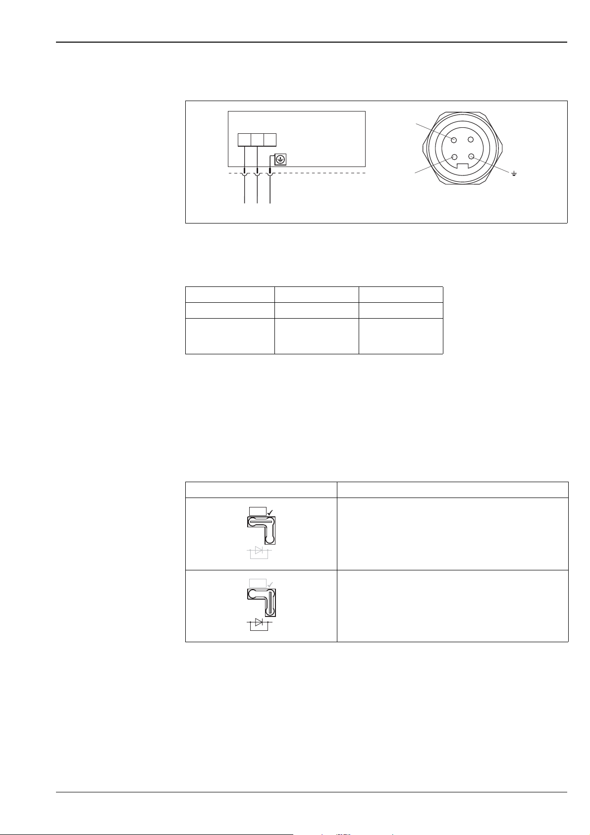
Electrical connection Note!
• When using the measuring device in hazardous areas, installation must comply with the corresponding
national standards and regulations and the Safety Instructions or Installation or Control Drawings. ä 82,
section "Safety Instructions" and "Installation/Control Drawings".
• Devices with integrated overvoltage protection must be earthed. ä 28.
• Protective circuits against reverse polarity, HF influences and overvoltage peaks are installed.
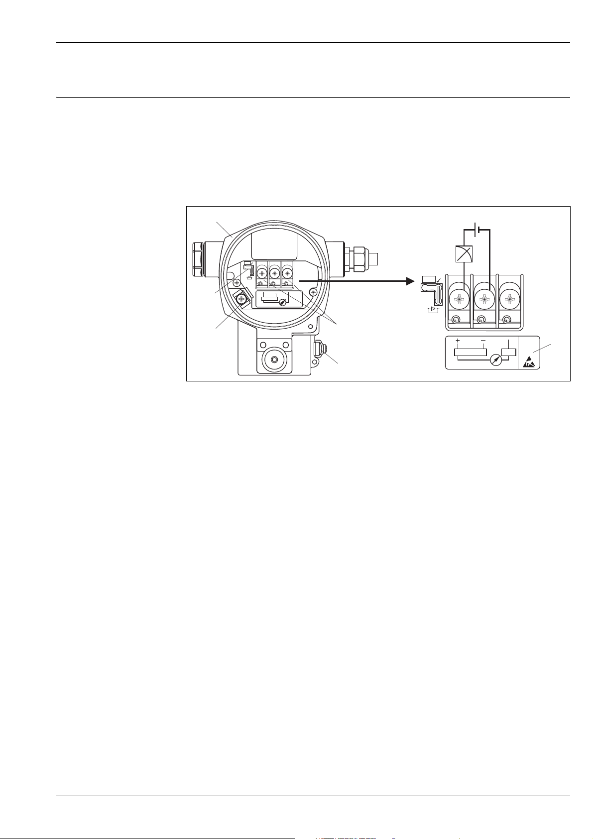
4...20 mA HART
P01-xMx7xxxx-04-xx-xx-xx-001
Electrical connection 4...20 mA HART
1 Housing
2 Jumper for 4...20 mA test signal. ä 17, section "Taking 4...20 mA test signal" .
3 Internal earth terminal
4 External earth terminal
5 4...20 mA test signal between positive and test terminal
6 minimum supply voltage = 10.5 V DC, jumper is inserted in accordance with the illustration.
7 minimum supply voltage = 11.5 V DC, jumper is inserted in "Test" position.
8 Devices with integrated overvoltage protection are labelled OVP (overvoltage protection) here ( ä 28).
PROFIBUS PA
The digital communication signal is transmitted to the bus via a 2-wire connection. The bus also provides the
auxiliary energy. For further information on the network structure and grounding and for further bus system
components such as bus cables, see the relevant documentation, e.g. Operating Instructions BA034S
"Guidelines for planning and commissioning PROFIBUS DP/PA" and the PNO Guideline.
Cable specifications:
• Use a twisted, shielded two-wire cable, preferably cable type A
Note!
For further information on the cable specifications, see Operating Instructions BA034S
Guidelines for planning and commissioning PROFIBUS DP/PA", PNO Guideline 2.092 "
PROFIBUS PA User and Installation Guideline" and IEC 61158-2 (MBP).
Endress+Hauser 15
Page 16
Deltabar S
Han7D
–
+
+–
–
+
1
5
4
6
7
8
2
3
M12
–
+
+–
–
+
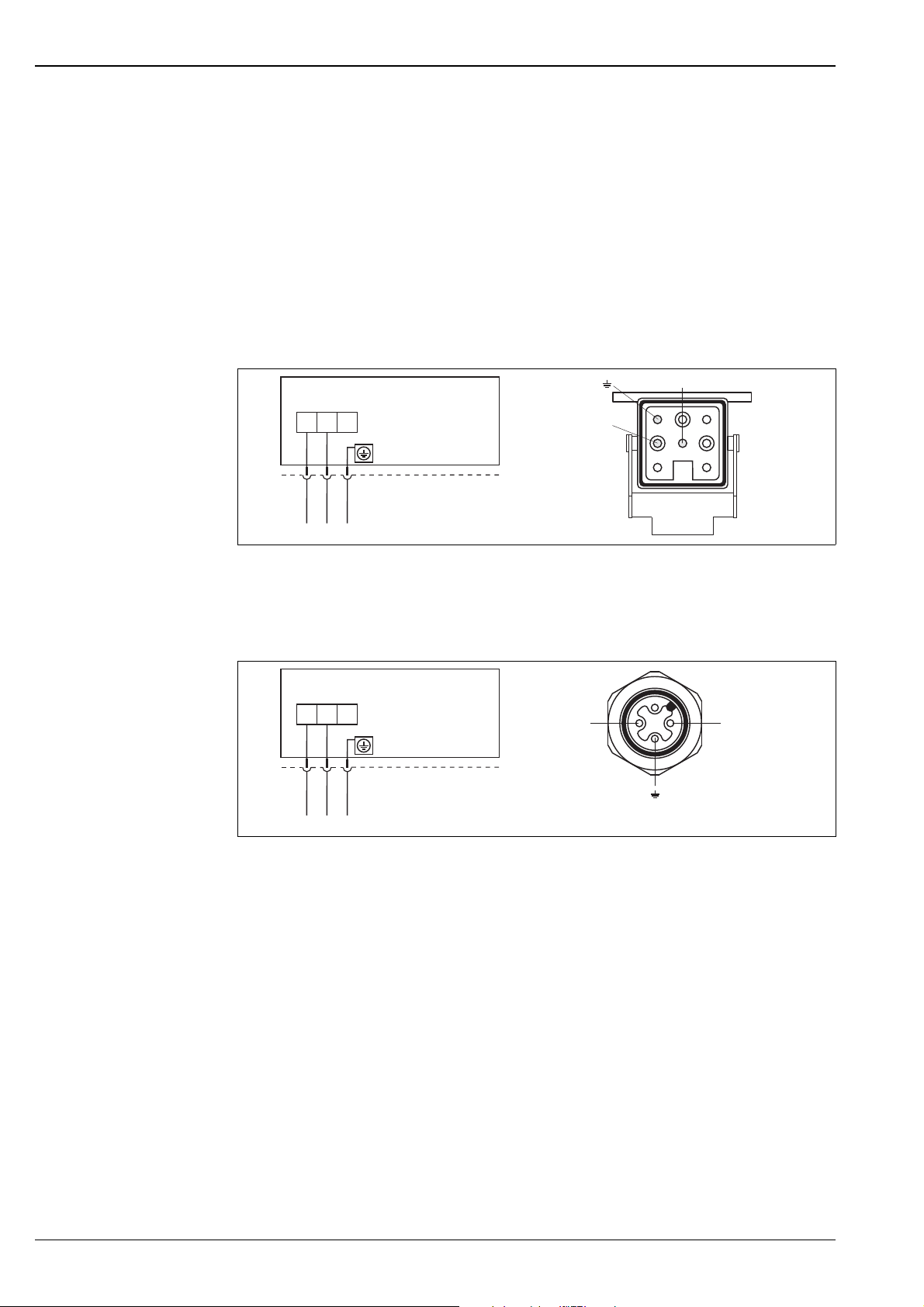
FOUNDATION Fieldbus
The digital communication signal is transmitted to the bus via a 2-wire connection. The bus also provides the
auxiliary energy. For further information on the network structure and grounding and for further bus system
components such as bus cables, see the relevant documentation, e.g. Operating Instructions BA013S
"FOUNDATION Fieldbus Overview" and the FOUNDATION Fieldbus Guideline.
Cable specifications:
• Use a twisted, shielded two-wire cable, preferably cable type A
Note!
For further information on the cable specifications, see Operating Instructions BA013S "FOUNDATION
Fieldbus Overview", FOUNDATION Fieldbus Guideline and IEC 61158-2 (MBP).
Devices with Harting plug Han7D
Left: electrical connection for devices with Harting plug Han7D
Right: view of the plug connector at the device
Devices with M12 plug
Left: electrical connection for devices with M12 plug
Right: view of the plug at the device
Endress+Hauser offers for devices with M12 plug the following accessories:
Plug-in jack M 12x1, straight
• Material: Body PA; coupling nut CuZn, nickel-plated
• Degree of protection (fully locked): IP67
• Order number: 52006263
Plug-in jack M 12x1, elbowed
• Material: Body PBT/PA; coupling nut GD-Zn, nickel-plated
• Degree of protection (fully locked): IP67
• Order number: 51006327
2
Cable 4x0.34 mm
• Material: Body PUR; coupling nut CuSn/Ni; cable PVC
• Degree of protection (fully locked): IP67
• Order number: 52010285
with M12 socket, elbowed, screw plug, 5 m length
P01-xMD7xxxx-04-xx-xx-xx-000
P01-xMD7xxxx-04-xx-xx-xx-008
16 Endress+Hauser
Page 17
Deltabar S
–
+
7/8”
–
+
+–
Test
TestTest
Devices with 7/8" plug
Left: electrical connection for devices with 7/8" plug
Right: view of the plug at the device
Kabel gland
Approval Typ Clamping range
Standard, II1/2G Exia, IS Plastic M20x1.5 5...10 mm
ATEX II1/2D, II1/3D,
II1/2GD Exia, II1GD Exia
II3G Ex nA
Metal M20x1.5 (Ex e) 7...10.5 mm
P01-xxx7xxxx-04-xx-xx-xx-003
Terminals
for wire cross-sections of 0.5 to 2.5 mm
2
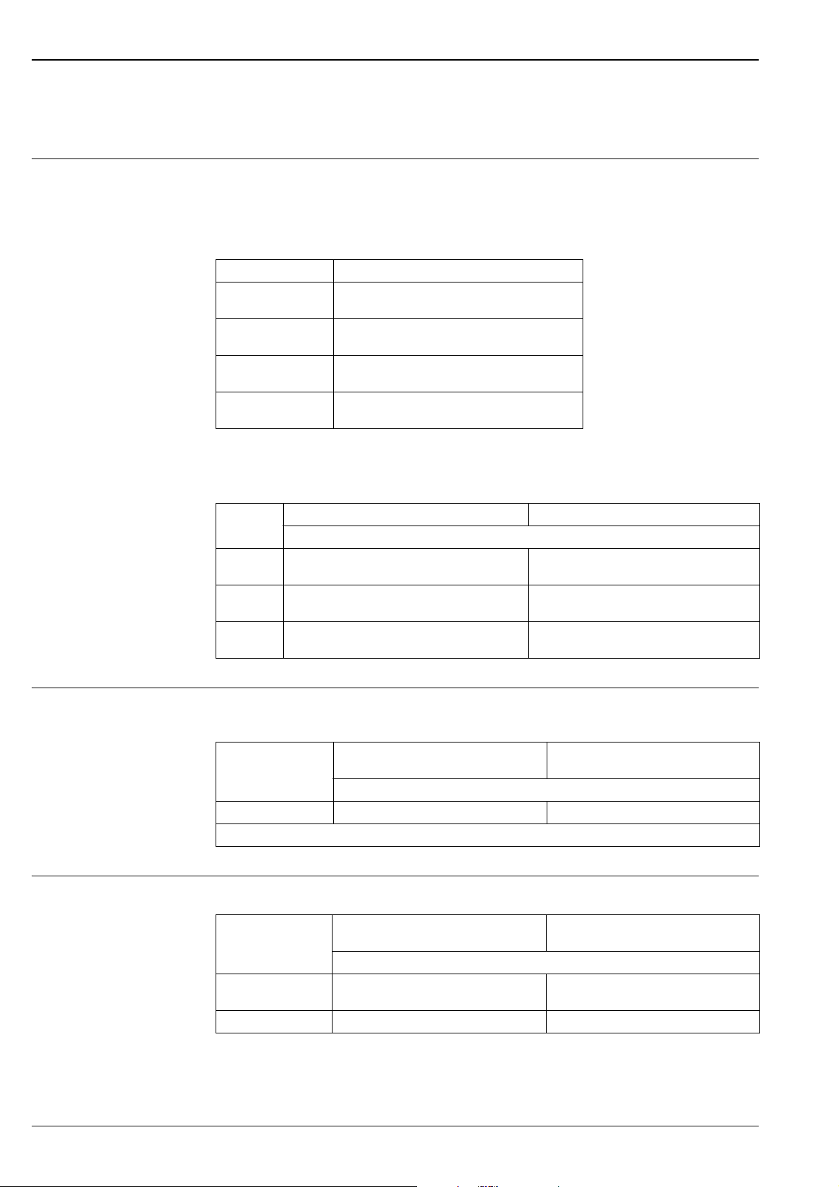
Taking 4...20 mA test signal
A 4...20 mA signal may be measured via the positive and test terminal without interrupting the measurement.
The minimum supply voltage of the device can be reduced by simply changing the position of the jumper. As
a result, operation is also possible with lower voltage sources. Observe the position of the jumper in accordance
with the following table.
Jumper position for test signal Description
– Taking 4...20 mA test signal via plus and test terminal:
possible. (Thus, the output current can be measured without
interruption via the diode.)
– Delivery status
– minimum supply voltage: 11.5 V DC
– Taking 4...20 mA test signal via plus and test terminal:
not possible.
– minimum supply voltage: 10.5 V DC
Endress+Hauser 17
Page 18

Supply voltage Note!
• When using the measuring device in hazardous areas, installation must comply with the corresponding
national standards and regulations and the Safety Instructions or Installation or Control Drawings.
• All explosion protection data are given in separate documentation which is available upon request. The Ex
documentation is supplied as standard with all devices approved for use in explosion hazardous areas.
ä 82, sections "Safety Instructions" and "Installation/Control Drawings".
4...20 mA HART
• Version for non-hazardous areas, jumper for 4...20 mA test signal in "Test" position (delivery status):
11.5...45 V DC
• Version for non-hazardous areas, jumper for 4...20 mA test signal in "Non-test" position: 10.5...45 V DC
PROFIBUS PA
• Version for non-hazardous areas: 9...32 V DC
FOUNDATION Fieldbus
• Version for non-hazardous areas: 9...32 V DC
Current consumption • PROFIBUS PA: 13 mA ± 1 mA, switch-on current corresponds to IEC 61158-2, Clause 21
• FOUNDATION Fieldbus: 15 mA ± 1 mA, switch-on current corresponds to IEC 61158-2, Clause 21
Deltabar S
Cable entry ä 67 ff, feature 30 "Housing, Cable entry, Protection".
Cable specification • Endress+Hauser recommends using shielded, twisted-pair two-wire cables.
• Terminals for wire cross-sections 0.5...2.5 mm
2
• Cable external diameter: 5...9 mm
Residual ripple Without influence on 4...20 mA signal up to 5 % residual ripple within the permitted voltage range [according
to HART hardware specification HCF_SPEC-54 (DIN IEC 60381-1)]
Influence of power supply 0.0006% of URL/1 V
18 Endress+Hauser
Page 19

Deltabar S
Performance characteristics – general
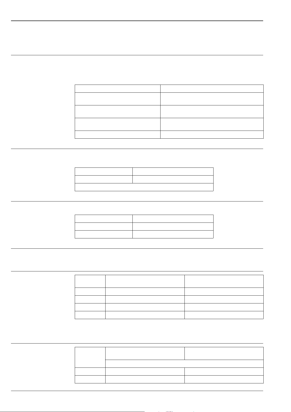
Reference operating conditions
Long-term stability
• As per IEC 60770
• Ambient temperature T
= constant, in the range of: +21...+33°C (+69.8...+91.4°F)
U
• Humidity = constant, in the range of: 5...80 % r.H
• Ambient pressure pU = constant, in the range of: 860...1060 mbar
• Position of the measuring cell: constant, in the range of: 1°
• Input of LOW SENSOR TRIM and HIGH SENSOR TRIM for lower range value and upper range value
• Zero based span
• Material of the process isolating diaphragm
– PMD75: AISI 316L/1.4435, Alloy C276, Gold-Rhodium coated, Monel
– FMD77, FMD78: AISI 316L/1.4435
– PMD70, FMD76: Al
(Aluminium-oxide-ceramic)
2O3
• Filling oil: silicone oil
• Side flanges material PMD75: AISI 316L/1.4435
• Supply voltage: 24 V DC ± 3 V DC
• Load with HART: 250
1 year 5 years 10 year
Measuring range [mbar] % of URL
10 ±0.150 -- --
100 ±0.180 -- --
500 ±0.025 ±0.050 ±0.075
3000 ±0.038 ±0.075 ±0.150
16000 ±0.025 ±0.110 ±0.210
Influence of the installation position
Vibration effects
• PMD70, FMD76: 3 mbar
• PMD75: 4 mbar
1, 3
• FMD77: 32 mbar
1) Device is rotated vertically to the axis of the process isolating diaphragm.
2) Device rotated vertically to the process isolating diaphragm of the flange .
3) The value is doubled for devices with inert oil.
1, 3
2, 3
Note!
Position-dependent zero shift can be corrected. ä 23, section "General installation instructions" and
ä 62 ff, section "Response time".
Device Housing Test standard Vibration effects
PMD70/
FMD76
PMD75 optional on-site display on
PMD75 optional on-site display on
optional on-site display on
the side (T14)
the side (T14)
the top (T15)
GL reference accuracy to
10...18 Hz: ±4 mm;
18...500 Hz: 5 g
reference accuracy to
10...38 Hz: ±0.35 mm;
IEC 61298-3
38...2000 Hz: 2 g
reference accuracy to
10...60 Hz: ±0.35 mm;
60...2000 Hz: 5 g
Endress+Hauser 19
Page 20
Deltabar S
Performance characteristics – metallic process isolating diaphragms
Reference accuracy –
PMD75, FMD77, FMD78
The reference accuracy comprises the non-linearity according to limit point setting, hysteresis and
non-reproducibility as per IEC 60770. The data refer to the calibrated span.
The following applies for the root-extracting characteristic curve:
The accuracy data of the Deltabar S is taken into the accuracy calculation of the flow rate with a factor of 0.5.
PMD75
Measuring cell % of the set span
10 mbar, 30 mbar
100 mbar
500 mbar
Platinum version:
00 mbar
• TD 1:1
• TD > 1:1
• TD 1:1 to TD 4:1
•TD > 4:1
• TD 1:1 to TD 15:1
•TD > 15:1
•TD 1:1 = ±0.05
==±0.15
±0.15 x TD
==±0.075
(0.012 x TD + 0.027)
==±0.075
(0.0015 x TD + 0.053)
FMD77, FMD78
Measuring
cell
100 mbar
500 mbar,
3 bar, 16 bar
40 bar
• TD 1:1 to TD 4:1
• TD > 4:1
• TD 1:1 to TD 15:1
•TD > 15:1
FMD77 FMD78
% of the set span (influence of the diaphragm seal included)
==±0.15
(0.03 x TD + 0.03)
==±0.075
(0.0015 x TD + 0.053)
• TD 1:1 to TD 4:1
• TD > 4:1
• TD 1:1 to TD 4:1
•TD > 4:1
• TD 1:1 to TD 4:1
•TD > 4:1
==±0.15
(0.03 x TD + 0.03)
==±0.15
(0.02 x TD + 0.07)
==±0.15
(0.02 x TD + 0.07)
Total performance – PMD75 The "Total performance" specification comprises the non-linearity including hysteresis, non-reproducibility, the
thermal change of the zero point as well as the influence of the line pressure (p
Measuring cell AISI 316L/1.4435, Alloy, Gold-Rhodium
or Monel process isolating diaphragm
% of the set span
500 mbar to TD 2:1 0.15 0.30
All specifications apply to the temperature range –10...+60°C (+14...+140°F).
Tantal process isolating diaphragm
= 70 bar).
st
Total Error The total error comprises the long-term stability and the total performance:
Measuring cell AISI 316L/1.4435, Alloy, Gold-Rhodium
10 mbar, 30 mbar,
100 mbar
500 mbar 0.20 0.35
or Monel process isolating diaphragm
% of URL/year
0.33 0.48
Tantal process isolating diaphragm
20 Endress+Hauser
Page 21
Deltabar S
Warm-up period –
PMD75, FMD77, FMD78
Influence of the operating pressure on zero point and span – PMD75, FMD77, FMD78
Thermal change of the zero
output and the output
span -- PMD75
• 4...20 mA HART : < 10 s
• PROFIBUS PA: 6 s
• FOUNDATION Fieldbus: 50 s
Measuring
cell
10 mbar 0.15 % of URL/7 bar 0.035 % of URL/7 bar 0.28 % of URL/7 bar 0.28 % of URL/7 bar
30 mbar 0.35 % of URL/70 bar 0.14 % of URL/70 bar 0.70 % of URL/70 bar 0.70 % of URL/70 bar
100 mbar 0.15 % of URL/70 bar 0.14 % of URL/70 bar 0.42 % of URL/70 bar 0.42 % of URL/70 bar
500 mbar 0.075 % of URL/70 bar 0.14 % of URL/70 bar 0.14 % of URL/70 bar 0.14 % of URL/70 bar
3 bar 0.075 % of URL/70 bar 0.14 % of URL/70 bar 0.14 % of URL/70 bar 0.14 % of URL/70 bar
16 bar 0.075 % of URL/70 bar 0.14 % of URL/70 bar 0.14 % of URL/70 bar 0.14 % of URL/70 bar
40 bar 0.075 % of URL/70 bar 0.14 % of URL/70 bar 0.14 % of URL/70 bar 0.14 % of URL/70 bar
AISI 316L/1.4435, Alloy, Gold-Rhodium
coated or Monel process isolating diaphragm
Influence of the
operating pressure on
the zero point
Influence of the
operating pressure on
the span
Tantal process isolating diaphragm
Influence of the
operating pressure on
the zero point
Influence of the
operating pressure on
the span
Note!
The influence of the operating pressure on the zero point can be calibrated out.
Measuring cell –10...+60 °C (+14...+140°F)
AISI 316L/1.4435, Alloy, Gold-Rhodium
coated or Monel process isolating
diaphragm
% of the set span
10 mbar, 30 mbar (0.31 x TD + 0.06)
100 mbar (0.18 x TD + 0.02) (0.24 x TD + 0.06)
500 mbar, 3 bar (0.08 x TD + 0.05)
16 bar (0.1 x TD + 0.1)
40 bar (0.08 x TD + 0.05)
Tantal process isolating diaphragm
Measuring cell –40...-10 °C, +60...+85 °C
10 mbar, 30 mbar (0.45 x TD + 0.1)
100 mbar (0.3 x TD + 0.15)
500 mbar, 3 bar (0.12 x TD + 0.1)
16 bar (0.15 x TD + 0.2)
40 bar (0.37 x TD + 0.1)
(–40...+14°F, +140...+185°F)
all process isolating diaphragm materials
% of the set span
Endress+Hauser 21
Page 22
Deltabar S
Performance characteristics – ceramic process isolating diaphragms
Reference accuracy –
PMD70, FMD76
Total performance –
PMD70, FMD76
The reference accuracy comprises the non-linearity including hysteresis and non-reproducibility in accordance
with the limit point method as per IEC 60770. The data refer to the calibrated span.
The following applies for the root-extracting characteristic curve:
The accuracy data of the Deltabar S is taken into the accuracy calculation of the flow rate with a factor of 0.5.
Measuring cell % of the set span
25 mbar
100 mbar
500 mbar, 3 bar
Platinum version: 100 mbar, 500 mbar, 3 bar • TD 1:1 = ±0.05
•TD 1:1
• TD > 1:1
• TD 1:1 to TD 4:1
•TD > 4:1
• TD 1:1 to TD 15:1
•TD > 15:1
==±0.15
±0.15 x TD
==±0.075
(0.012 x TD + 0.027)
==±0.075
(0.0015 x TD + 0.05252)
The "Total performance" specification comprises the non-linearity including hysteresis, non-reproducibility, the
thermal change of the zero point as well as the influence of the line pressure (p
Measuring cell % of the set span
500 mbar to TD 1:1 • 0.15
All specifications apply to the temperature range –10...+60°C (+14...+140°F).
= 70 bar).
st
Total Error The total error comprises the long-term stability and the total performance:
Measuring cell % of URL/year
25 mbar, 100 mbar • 0.33
500 mbar, 3 bar • 0.20
Warm-up period –
PMD70, FMD76
• 4...20 mA HART : < 10 s
• PROFIBUS PA: 6 s
• FOUNDATION Fieldbus: 50 s
Influence of the operating pressure on zero point and span – PMD70, FMD76
Measuring cell Influence of the operating pressure on the
zero point
25 mbar 0.7 % of URL/7 bar 0.14 % of URL/7 bar
100 mbar 0.175 % of URL/70 bar 0.14 % of URL/70 bar
500 mbar 0.075 % of URL/70 bar 0.14 % of URL/70 bar
3 bar 0.075 % of URL/70 bar 0.14 % of URL/70 bar
Influence of the operating pressure on the
span
Note!
The influence of the operating pressure on the zero point can be calibrated out.
Thermal change of the zero
output and the output span –
PMD70, FMD76
Measuring cell –10...+60 °C
(+14...+140°F)
% of the set span
25 mbar (0.35 x TD + 0.05) (0.3 x TD + 0.15)
100 mbar (0.05 x TD + 0.05) (0.08 x TD + 0.07)
–20...–10 °C, +60...+85 °C
(–4...+14°F, +140...+185°F)
22 Endress+Hauser
Page 23

Deltabar S
Operating conditions (Installation)
General installation instructions
Measuring arrangement Flow measurement
• The position-dependent zero shift can be corrected directly at the device via operating key, for devices with
external operation even in hazardous areas. Diaphragm seals also shift the zero point, depending on the
installation position ( ä 64 ff, "Installation instructions").
• The housing of the Deltabar S can be rotated up to 380°. ä 26, section "Turn the housing".
• Endress+Hauser offers a mounting bracket for installing the device on pipes or walls. ä 24, section "Wall-
and pipe-mounting".
• When measuring in media with solid proportions, such as dirty liquids, installing separators and drain valves
is useful for capturing and removing sediment.
• Using a three-valve or five-valve manifold allows for easy commissioning, installation and maintenance
without interrupting the process.
• General recommendations for the impulse piping can be found in DIN 19210 "Methods for measurement of
fluid flow; differential piping for flow measurement devices" or the corresponding national or international
standards.
• Install the impulse piping with a continuous gradient of at least 10%.
• When routing the impulse piping outdoors, ensure that sufficient anti-freeze protection is used, e.g. by using
pipe heat tracing.
• For FMD77 and FMD78: See page 64 ff, "Installation instructions, Diaphragm seal systems" section.
• The PMD70 and PMD75 are best suited to flow measurement.
• Measuring arrangement for gases: Mount device above the measuring point.
• Measuring arrangement for liquids and vapours: Mount device below tapping point.
• For flow measurement in vapours, mount the condensate traps at the same level as the same the tapping
point and at the same distance from Deltabar S.
Level measurement
• PMD70, PMD75, FMD76 and FMD77 are best suited to level measurement in open tanks. All Deltabar S
devices are suitable for level measurement in closed tanks.
Measuring arrangement level measurement in open tanks
• PMD70, PMD75: Mount device below the lower measuring connection. The negative side is open to
atmosphere pressure.
• FMD76, FMD77: Mount device direct on the tank. The negative side is open to atmosphere pressure.
Measuring arrangement level measurement in closed tanks and closed tanks with superimposed vapour
• PMD70, PMD75: Mount device below the lower measuring connection. Always connect the negative side
above the maximum level.
• FMD76, FMD77: Mount device direct on the tank. Always connect the negative side above the maximum
level.
• In the case of level measurement in closed tanks with superimposed vapour, a condensate trap ensures
pressure which remains constant on the minus side.
Pressure measurement
• The PMD70 and PMD75 are best suited to differential pressure measurement.
• Measuring arrangement for gases: Mount device above the measuring point.
• Measuring arrangement for liquids and steams: Mount device below tapping point.
• For differential pressure measurement in vapour, mount the condensate traps at the same level as the same
the tapping point and at the same distance from Deltabar S.
Endress+Hauser 23
Page 24
Deltabar S
λ 0.04≤
W
mK•
T
A
T
P
106
74
74
124
135
37.5
➀
Heat insulation – FMD77 The FMD77 must only be insulated up to a certain height. The maximum permitted insulation height is labelled
on the devices and applies to an insulation material with a heat conductivity
0.04 W/(m x K) and to the maximum permitted ambient and process temperature ( see table below). The
data were determined under the most critical application "quiescent air".
P01-FMD77xxxx-11-xx-xx-xx-000
Maximum permitted insulation height
FMD77
Ambient temperature (T
) 70°C (158°F)
A
Process temperature (TP) max. 400°C (752°F), depending on the
diaphragm seal filling oil used ( see
page 59)
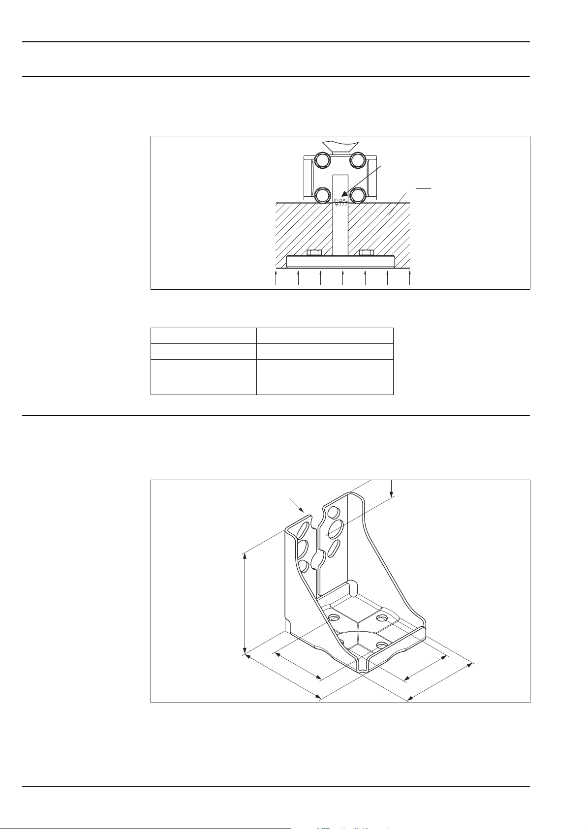
Wall- and pipe-mounting Endress+Hauser offers a mounting bracket for installing the device on pipes or walls. ä 67 ff, feature 110,
"Additional options 2".
Note!
If a valve block is used, its dimensions should also be taken into consideration.
P01-xMD7xxxx-11-xx-xx-xx-008
Mounting bracket for wall and pipe-mounting
A bracket including mounting accessories for pipe mounting is included with the device.
1 Device mounting
24 Endress+Hauser
Page 25
Deltabar S
➀
➁
➂
➃
r ³ 120 mm
IP xx
(see chapter
“Ordering information”)
FEP cable:
IP 69K
IP 66/68 NEMA 4/6P
PE cable:
IP 66/68 NEMA 4/6P
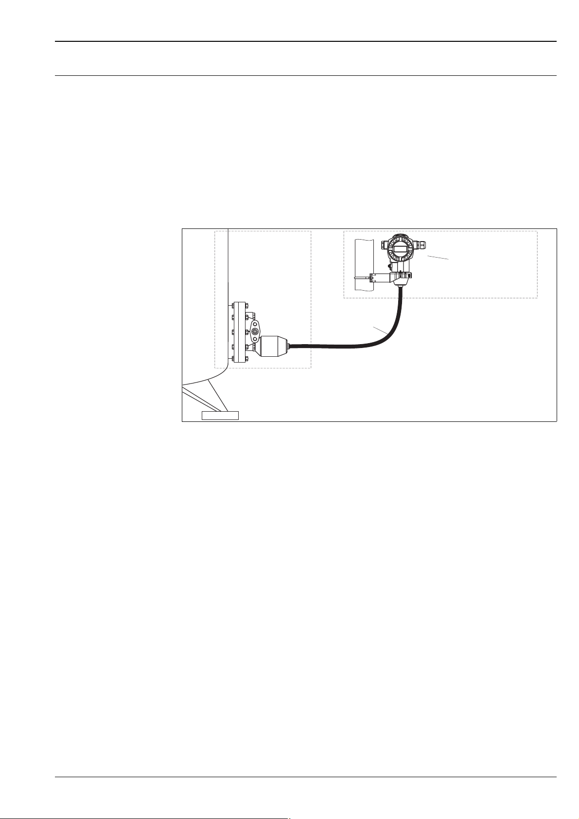
"Separate housing" version With the "separate housing" version, you are able to mount the housing with the electronics insert at a distance
from the measuring point. This facilitates trouble-free measurement:
• Under particularly difficult measuring conditions (at installation locations that are cramped or difficult to
access)
• If rapid cleaning of the measuring point is required
• If the measuring point is exposed to vibrations.
You can choose between different cable versions:
• PE (2 m, 5 m and 10 m)
• FEP (5 m).
ä 68 ff, Feature 110, "Additional options 2", Version "G".
For the dimensions, see ä 50.
P01-xMD7xxxx-11-xx-xx-en-010
In the case of the "separate housing" version, the sensor is delivered with the process connection and cable ready
mounted. The housing and a mounting bracket are enclosed as separate units. The cable is provided with a socket at both
ends. These sockets are simply connected to the housing and the sensor.
1 Process connection with sensor
2 Cable, both ends are fitted with a socket
3 Mounting bracket provided, suitable for pipe and wall mounting
4 Housing with electronic insert
Degree of protection for the process connection with sensor with the use of
• FEP cable:
– IP 69K
– IP 66 NEMA 4/6P
– IP 68 (1.83 mH
O for 24 h) NEMA 4/6P
2
• PE cable:
– IP 66 NEMA 4/6P
– IP 68 (1.83 mH
O for 24 h) NEMA 4/6P
2
Technical data of the PE and FEP cable:
• Minimum bending radius: 120 mm (4.72 inch)
• Cable extraction force: max. 450 N
• Resistance to UV light
Use in hazardous area:
• Intrinsically safe installations (Ex ia/IS)
• FM/CSA IS: for Div.1 installatin only
Endress+Hauser 25
Page 26
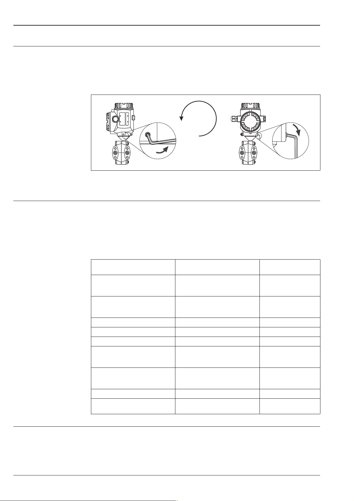
Turn the housing The housing can be rotated up to 380° by loosening the Allen screw.
max. 380°
Your benefits
• Simple mounting by optimally aligning the housing
• Good, accessible device operation
• Optimum readability of the on-site display (optional).
Align the housing by loosening the Allen screw.
T14 and T15 housing: 2 mm Allen key; T17 housing: 3 mm Allen key
Deltabar S
P01-xMD7xxxx-17-xx-xx-xx-001
Oxygen applications Oxygen and other gases can react explosively to oils, grease and plastics, such that, among other things, the
following precautions must be taken:
– All components of the system, such as measuring devices, must be cleaned in accordance with the BAM
(DIN 19247) requirements.
– Dependent on the materials used, a certain maximum temperature and a maximum pressure for oxygen
applications must not be exceeded.
The devices suitable for gaseous oxygen applications are listed in the following table with the specification p
Order code for devices cleaned for
oxygen applications
PMD70 – ********2**,
Devices with 500 mbar or 3000 mbar
measuring cell
PMD70 – ********2**,
Devices with 25 mbar or 100 mbar
measuring cell
PMD75 – * * * ** * * * K * * 160 bar
PMD75 – * * * ** * * * 2 * * 160 bar 60°C (140°F)
PMD75 – * * * ** * * * 3 * * 160 bar 60°C (140°F)
FMD76 – ******T***,
Devices with 500 mbar or 3000 mbar
measuring cell
FMD76 – ******T***,
Devices with 25 mbar or 100 mbar
measuring cell
FMD77 – *****T*F** PN of the flange 60°C (140°F)
FMD78 – ********4**
FMD78 – ********D**
p
for oxygen applications T
max
30 bar 60°C (140°F)
PN of the flange 60°C (140°F)
30 bar 60°C (140°F)
PN of the measuring cell 60°C (140°F)
90 bar 85°C (185°F)
for oxygen
max
applications
85°C (185°F)
max
.
Ultra pure gas applications Endress+Hauser also offers devices for special applications, such as ultra pure gas, cleaned from oil and grease.
No special restrictions regarding the process conditions apply to these devices.
ä 67 ff, PMD70 and PMD75: feature 80 "Seal", FMD76 and FMD77: feature 70 "Process connection low-
pressure side, material, seal".
26 Endress+Hauser
Page 27

Deltabar S
Process isolating diaphragms for materials with hydrogen build-up (Gold-Rhodium coating)
With regard to materials in which hydrogen build-up takes place, hydrogen atoms can diffuse through the
metalic process isolating diaphragms. This can result in incorrect measurement results.
Endress+Hauser offers process isolating diaphragms with Gold-Rhodium coating for this application.
ä 71 ff "Ordering information PMD75", ä 70 "Ordering information FMD77" or ä 76 "Ordering
information FMD78", feature 60 "Process isolating diaphragm material".
Operating conditions (Environment)
Ambient temperature range • PMD75, FMD77, FMD78: –40...+85°C (–40...+185°F), devices for lower temperatures on request
• PMD70, FMD76: –20...+85°C (–4...+185°F)
• On-site display: –20...+70°C (–4...+158°F)
Extended temperature application range with restrictions in optical properties such as display speed and
contrast: –40...+85°C (–40...+185°F)
• Separate housing: –40 to +60°C (–40 to +140°F)
For devices for use in hazardous areas, see Safety instructions, Installation or Control Drawing ( ä 82,
sections "Safety Instructions" and "Installation/Control Drawings").
The device can be used in this temperature range. The values of the specification, such as thermal change, may
be exceeded. See also DIN 16086.
Storage temperature range • –40...+ 90°C (–40...+194°F)
• On-site display: –40...+85°C (–40...+185°F)
• Separate housing: –40 to +60°C (–40 to +140°F)
Degree of protection • ä 67 ff, feature 30 "Housing, Cable entry, Protection".
• Degree of protection IP 68 for T17 housing: 1.83 mH
O for 24 h
2
• Seperate housing ä 25
Climate class Class 4K4H (air temperature: –20...55°C/–4...+131F, relative humidity: 4...100%) fulfilled as per
DIN EN 60721-3-4 (condensation possible)
Vibration resistance
Device/Additional option Housing Test standard Vibration resistance
PMD70/
FMD76
PMD75 optional on-site display on
PMD75 optional on-site display on
with mounting bracket IEC 61298-3 guaranteed for:
optional on-site display on
the side (T14)
the side (T14)
the top (T15)
GL guaranteed for:
2...18 Hz: ±4 mm;
18...500 Hz: 5 g in all 3 planes
IEC 61298-3 guaranteed for:
10...60 Hz: ±0.35 mm;
60...2000 Hz: 5 g in all 3 planes
10...60 Hz: ±0.15 mm;
60...500 Hz: 2 g in all 3 planes
Electromagnetic compatibility • Electromagnetic compatibility to EN 61326 and NAMUR recommendation EMC (NE21). For details refer
to the declaration of conformity.
• With enhanced immunity against electromagnetic fields as per EN 61000-4-3:
30 V/m with closed cover (for devices with T14 or T15 housing)
• Maximum deviation: < 0.5% of span
1
• All EMC measurements were performed with a turn down (TD) = 2:1.
1) Larger deviations possible with PMD70 with 25 mbar or 100 mbar sensor
Endress+Hauser 27
Page 28

Deltabar S
Overvoltage protection (optional)
• Overvoltage protection:
– Nominal functioning DC voltage: 600 V
– Nominal discharge current: 10 kA
• Surge current check î = 20 kA as per DIN EN 60079-14: 8/20 s satisfied
• Arrester AC current check I = 10 A satisfied
ä 68 ff, feature 100 "Additional options 1" and feature 110 "Additional options 2", version "M Overvoltage
protection".
Note!
Devices with integrated overvoltage protection must be earthed.
Operating conditions (Process)
Process temperature limits • PMD70: –20...+85°C (–4...+185°F)
• FMD76: –20...+85 °C (–4...+185°F)
• PMD75 with impulse piping longer than 100 mm: –40...+120°C (–40...+248°F),
with side flanges C22.8 and impulse piping longer than 100 mm: –10...+120°C (14...+248°F)
• FMD77 and FMD78, depending on the diaphragm seal and filling oil: up to + 400°C (+752°F)
Note!
• For oxygen applications, observe page 26 "Oxygen applications" section.
• PMD70, FMD76, PMD75 and FMD78: Observe the Process temperature range of the seal.
See also the following section "Process temperature range, seals".
• FMD77 and FMD78: Observe the temperature application limits of the diaphragm seal oil.
ä 59, sections "Diaphragm seal filling oils".
• FMD77 and FMD78: Do not use diaphragm seals with 0.09 mm PTFE foil on AISI 316L (1.4435/1.4405)
for vacuum applications, upper temperature limit +204°C (+400°F).
Process temperature range, seals
PMD70 (with ceramic process isolating diaphragms)
Versions for feature 80 in the order code Seal Process temperature range
A FKM Viton –20...+85°C (–4...+185°F)
B EPDM –20...+85°C (–4...+185°F)
D Kalrez, Compound 4079 +5...+85°C (+41...+185°F)
E Chemraz, Compound 505 –20...+85°C (–4...+185°F)
1 FKM Viton, cleaned from oil and greace –10...+85°C (+14...+185°F)
2 FKM Viton, cleaned for oxygen service –10...+60°C (+14...+140°F)
FMD76 (with ceramic process isolating diaphragms)
Versions for feature 70 in the order code Seal Temperature operating range
B, D, F, G, U FKM Viton –20...+85°C (–4...+185°F)
K, L EPDM
FDA 21 CFR 177.2600
M, N Kalrez, Compound 4079 +5...+85°C (+41...+185°F)
P, Q Chemraz, Compound 505 –20...+85°C (–4...+185°F)
S FKM Viton, cleaned from oil and greace –10...+85°C (+14...+185°F)
T FKM Viton, cleaned for oxygen service –10...+60°C (+14...+140°F)
–20...+85°C (–4...+185°F)
28 Endress+Hauser
Page 29

Deltabar S
PMD75 (with metallic process isolating diaphragms)
Versions for feature 80 in the
order code
A FKM Viton –20...+85°C (–4...+185°F)
C PTFE –40...+85°C (–40...+185°F)
F NBR –20...+85°C (–4...+185°F)
H Copper –40...+85°C (–40...+185°F)
K Copper, cleaned for oxygen service –20...+85°C (–4...+185°F)
1 FKM Viton, cleaned from oil and greace –10...+85°C (+14...+185°F)
2 FKM Viton, cleaned for oxygen service –10...+60°C (+14...+140°F)
3 PTFE, cleaned for oxygen service –20...+60°C (–4...+140°F)
1) lower temperature on request
Seal Process temperature range
FMD77 (with metallic process isolating diaphragms)
Versions for feature 70 in the
order code
B, D, F, G FKM Viton –20...+85°C (–4...+185°F)
H, J PTFE –40...+85°C (–40...+185°F)
K, L EPDM –40...+85°C (–40...+185°F)
M, N Kalrez, Compound 6375 +5...+85°C (+41...+185°F)
P, Q Chemraz, Compound 505 –20...+85°C (–4...+185°F)
S FKM Viton, cleaned from oil and greace –10...+85°C (+14...+185°F)
T FKM Viton, cleaned for oxygen service –10...+60°C (+14...+140°F)
Seal on the LP side (–) Process temperature range
1
1
1) lower temperature on request
Pressure specifications • The maximum pressure for the measuring device is dependent on the lowest-rated element with regard to
pressure, see the following sections for this:
– ä 8 ff, section "Measuring range"
– chapter "Mechanical construction".
The MWP (maximum working pressure) is specified on the nameplate. This value refers to a reference
temperature of 20°C (68°F) or 100°F for ANSI flanges and may be applied to the device for an unlimited
time. Observe pressure-temperature dependency.
• The pressure values permitted at higher temperatures can be found in the following standards:
– EN 1092-1: 2001 Tab. 18
1
– ASME B 16.5a – 1998 Tab. 2-2.2 F316
– ASME B 16.5a – 1998 Tab. 2.3.8 N10276
– JIS B 2220
• For PMD70 and PMD75, the MWP applies for the temperature ranges specified in the "Ambient temperature
range" ( ä 27) and "Process temperature limits" ( ä 28) sections.
• The test pressure corresponds to the over pressure limit of the measuring instrument (Over pressure limits
OPL = 1.5 x MWP) and may fit only temporally limited, so that no permanent damage develops.
• The Pressure Equipment Directive (EC Directive 97/23/EC) uses the abbreviation "PS". The abbreviation
"PS" corresponds to the MWP (maximum working pressure) of the measuring device.
• In the case of sensor range and process connections where the OPL (Over Pressure Limit) of the pressure
connection is smaller than the nominal value of the sensor, the device is set at the factory, at the very
maximum, to the OPL value of the process connection. If you want to use the entire sensor range, select a
process connection with a higher OPL value (1.5 x PN; PN = MWP).
• In oxygen applications, the values for "p
max
and T
for oxygen applications" as per ä 26, "Oxygen
max
applications" may not be exceeded.
1) With regard to their stability-temperature property, the materials 1.4435 and 1.4404 are grouped together under 13EO
in EN 1092-1 Tab. 18.
The chemical composition of the two materials can be identical.
Endress+Hauser 29
Page 30

Housing dimensions T14,
FIELDTERMINALSFIELDTERMINALS
111
152
111
H
115 127
155
H
H
102
132
115
H
optional display on the side
Housing dimensions T15, optional display on the top
Deltabar S
Mechanical construction
P01-xMD7xxxx-06-00-xx-xx-000
Front view, left-hand side view, top view
See the process connection in question for installation height. Housing weight see ä 51.
Housing dimensions T17, optional display on the top
Front view, left-hand side view, top view
See the process connection in question for installation height. Housing weight see ä 51.
Front view, left-hand side view, top view
See the process connection in question for installation height. Housing weight see ä 51.
P01-xMD7xxxx-06-00-xx-xx-001
P01-xMD7xxxx-06-00-xx-xx-002
30 Endress+Hauser
Page 31

Deltabar S
41.3
54
84
96
108
M10
7/16-20 UNF
RC1/4
1/4-18 NPT
H
+
–
+
+
–
Process connections PMD70 with ceramic process isolating diaphragms
Note!
Some device versions have CRN approval. For a CRN-approved device, a CRN-approved process connection
( ä 68, feature 70 "Process connection") has to be ordered with a CSA approval ( ä 67, feature 10
"Approval"). These devices are fitted with a separate plate bearing the registration number 0F10524.5C.
P01-PMD70xxx-06-09-xx-xx-000
Process connection PMD70, oval flange
H Device height see ä 32, section "Device height H"
Ver-
Connection Mounting Material Accessories Weight
sion
B 1/4-18 NPT IEC 61518 7/16-20 UNF Steel C 22.8 2 vent valves (AISI 316L/1.4404)
included
D 1/4-18 NPT IEC 61518 7/16-20 UNF AISI 316L
F 1/4-18 NPT IEC 61518 7/16-20 UNF Alloy C276
2
3
Vent valves (Alloy C276/2.4819),
see ä 68 feature 110
"Additional options 2".
U RC 1/4 7/16-20 UNF AISI 316L
1 1/4-18 NPT IEC 61518 PN 160: M10 Steel C 22.8 4.0 kg
2 1/4-18 NPT IEC 61518 PN 160: M10 AISI 316L
3 1/4-18 NPT IEC 61518 PN 160: M10 Alloy C276
2
2 vent valves (AISI 316L/1.4404)
included
2
3
Vent valves (Alloy C276/2.4819),
see ä 68, feature 110
"Additional options 2".
1
4.0 kg
4.0 kg
4.2 kg
4.0 kg
4.0 kg
4.2 kg
1) Process connection weight, for housing weight see ä 51
2) AISI 316L/1.4435
3) Alloy C276/2.4819
Endress+Hauser 31
Page 32

Process connections PMD70
41.3
54
84
96
PVDF
108
7/16-20 UNF
1/4-18 NPT
H
+
–
+
with ceramic process isolating
(continued)
Deltabar S
P01-PMD70xxx-06-09-xx-xx-001
Process connection PMD70, version G, PVDF inlay, PN = 10 bar, process temperature T = –10...+60°C (14...+140°F)
H Device height see ä 32, section "Device height H"
Version Connection Mounting Material Weight
G 1/4-18 NPT IEC 61518 7/16-20 UNF PVDF 3.8 kg
1) Process connection weight, for housing weight see ä 51
Device height H
Description Device height H
T14 housing, optional display on the side 253 mm
T15 housing without display, flat cover 259 mm
T15 housing with display, high cover 271.5 mm
T17 housing, optional display on the side 269 mm
1
32 Endress+Hauser
Page 33

Deltabar S
H
7/16-20 UNF
RC1/4
1/4-18 NPT
+
–
100
72
98
41.3
54
M10 (M12)
87
106
M 10
41.3
+
–
85
H
54
85
100
7/16-20 UNF
RC1/4
1/4-18 NPT
+
–
+
–
Process connections PMD75 with metallic process isolating diaphragms
Note!
Some device versions have CRN approval. For a CRN-approved device, a CRN-approved process connection
( ä 71, feature 70 "Process connection") has to be ordered with a CSA approval ( ä 68, feature 10
"Approval"). These devices are fitted with a separate plate bearing the registration number 0F10524.5C.
Oval flange, connection 1/4-18 NPT or RC 1/4
P01-PMD75xxx-06-09-xx-xx-005
Process connection PMD75,
above 10 mbar and 30 mbar measuring cell; below: Measuring cell 100 mbar
H Device height see ä 35, section "Device height H"
Ver-
Connection Mounting Material Accessories Weight
sion
B 1/4-18 NPT IEC 61518 7/16-20 UNF Steel C 22.8 2 vent valves (AISI 316L/1.4404)
included
D 1/4-18 NPT IEC 61518 7/16-20 UNF AISI 316L
F 1/4-18 NPT IEC 61518 7/16-20 UNF Alloy C276
U RC 1/4 7/16-20 UNF AISI 316L
1 1/4-18 NPT IEC 61518 – PN 160: M10
– PN 420: M12
2 1/4-18 NPT IEC 61518 – PN 160: M10
3 1/4-18 NPT IEC 61518 – PN 160: M10
1) Weight of process connections without vent valves with 10 mbar or 30 mbar sensors, process connections without
2) AISI 316L/1.4435 or 1.4404
3) Alloy C276/2.4819
vent valves with sensors 100 mbar weght approx. 800 g less. Housing weight see ä 51.
– PN 420: M12
– PN 420: M12
Steel C 22.8 4.2 kg
AISI 316L
Alloy C276
2
3
Vent valves (Alloy C276/2.4819),
see ä 72, feature 110
"Additional options 2".
2
2 vent valves (AISI 316L/1.4404)
included
2
3
Vent valves (Alloy C276/2.4819),
see ä 72 ff, feature 110
"Additional options 2".
1
4.2 kg
4.2 kg
4.5 kg
4.2kg
4.2 kg
4.5 kg
Endress+Hauser 33
Page 34

Deltabar S
106
41.3
+
–
85
42
H
54
85
100
7/16-20 UNF
RC1/4
1/4-18 NPT
1/4-18 NPT
+
–
H
7/16-20 UNF
RC1/4
1/4-18 NPT
1/4-18 NPT
+
–
100
72
98
41.3
28
54
87
+
–
Process connections PMD75 with metallic process isolating diaphragms (continued)
Oval flange, connection 1/4-18 NPT or RC 1/4, with side vent
P01-PMD75xxx-06-09-xx-xx-004
Process connection PMD75, 10 mbar and 30 mbar measuring cell
P01-PMD75xxx-06-09-xx-xx-003
Process connection PMD75, nominal value 100 mbar
H Device height see ä 35, section "Device height H"
Ver-
Connection Mounting Material Accessories Weight
sion
C 1/4-18 NPT IEC 61518 7/16-20 UNF Steel C 22.8 4 locking screws and
E 1/4-18 NPT IEC 61518 7/16-20 UNF AISI 316L
H 1/4-18 NPT IEC 61518 7/16-20 UNF Alloy C276
V RC 1/4 7/16-20 UNF AISI 316L
1) Weight of process connections without vent valves with 10 mbar or 30 mbar sensors, process connections without
vent valves with sensors 100 mbar weght approx. 800 g less. Housing weight see ä 51
2) PN 160 bar measuring cells: AISI 316L/1.4435, PN 420 bar measuring cells: AISI 316L/1.4435 or 1.4404
3) Alloy C276/2.4819
2 vent valves included
2
(AISI 316L/1.4404)
3
Vent valves (Alloy C276/2.4819),
see ä 72, feature 110
"Additional options 2".
2
4 looking screws and
2 vent valves included
(AISI 316L/1.4404)
1
4.2 kg
4.2 kg
4.5 kg
4.2 kg
34 Endress+Hauser
Page 35

Deltabar S
➁
H
7/16-20 UNF
M6
+
–
+
–
72
41.3
98
54 54
87
➀
➂
Process connections PMD75 with metallic process isolating diaphragms (continued)
Oval flange, prepared for diaphragm seal mount
Left: Process connection PMD75, version W, prepared for diaphragm seal mount
Right: Position of the copper ring seal
H Device height see the following section "Device height H"
1 Diaphragm seal attachment
2 Copper ring seal
3 Process isolating diaphragm
Device height H
Description Device height H
T14 housing, optional display on the side 217 mm (230 mm)
T15 housing without display, flat cover 223 mm (236 mm)
T15 housing with display, high cover 235.5 mm (248.5 mm)
T17 housing, optional display on the side 233 mm (246 mm)
1
P01-PMD75xxx-06-09-xx-xx-002
1) Values for devices with 10 mbar and 30 mbar measuring cell in brackets
Endress+Hauser 35
Page 36

Deltabar S
41.3
41
k
g
b
H
2
ø46
g
2
D
h
7/16-20 UNF
1/4-18 NPT
Process connection FMD76 with ceramic process isolating diaphragms
Note!
• Some device versions have CRN approval. For a CRN-approved device, a CRN-approved process connection
( ä 74, feature 70 "Process connection") has to be ordered with a CSA approval ( ä 73, feature 10
"Approval"). These devices are fitted with a separate plate bearing the registration number 0F10524.5C.
• FMD76 devices with an EN/DIN flange DN 80 PN 40, an ANSI flange 3" 150 lbs or a JIS flange 80 A 10 K
can only be mounted with an open-ended wrench.
EN/DIN flanges, connection dimensions as per EN 1092-1/DIN 2527
P01-FMD76xxx-06-09-xx-xx-000
Process connection FMD76, high-pressure side: EN/DIN flange,
low-pressure side: connection 1/4-18 NPT
Application limits for version "G" in feature 70 "Process connection low-pressure side" with PVDF inlay:
PN = 10 bar, process temperature T = –10...+60°C (14...+140°F)
H Device height see ä 38, section "Device height H, devices with flange"
h Height of the device without flange thickness b
1
Flange
Version Material Nominal
diameter
Shape 2Nominal
pressure
Diameter Thickness Raised
face
Boltholes
Quantity Diameter Hole
circle
Flange
weight
3
Db g g2k
[mm] [mm] [mm] [mm] [mm] [kg]
B AISI 316L DN 80 B1 (D) PN 10-40 200 24 138 8 18 160 5.3
DECTFE
E Alloy C276
4
DN 80 – PN 10-40 200 24 – 8 18 160 5.3
5
DN 80 B1 (D) PN 10-40 200 24 138 8 18 160 6
F AISI 316L DN 100 B1 (C) PN 10-16 220 22 – 8 18 180 6
G AISI 316L DN 100 B1 (D) PN 25-40 235 26 162 8 22 190 8
HECTFE
J Alloy C276
LECTFE
DN 100 – PN 25-40 235 26 – 8 22 190 8
DN 100 B1 (D) PN 25-40 235 26 162 8 22 190 9
DN 100 – PN 10-16 220 22 – 8 18 180 6
M Alloy C276 DN 100 B1 (C) PN 10-16 220 22 – 8 18 180 6.8
1) The roughness of the surface in contact with the medium, including the sealing surface of the flanges (all standards), made of Hastelloy C, Monel or
Tantalum is Ra 0.8 μm. Lower surface roughness on request.
2) Designation as per DIN 2527 in brackets
3) Housing weight see ä 51
4) ECTFE coating on AISI 316L/1.4435,
When operating in hazardous area, avoid electrostatic charge of the plastic surfaces.
5) Alloy C276/2.4819
36 Endress+Hauser
Page 37

Deltabar S
41.3
41
1.61 in
k
g
b
H
1.6 (0.06 in)
1.63 in
ø46
ø1.81 in
g
2
D
h
7/16-20 UNF
1/4-18 NPT
2(0.078 in)
ANSI
JIS
Process connection FMD76 with ceramic process isolating diaphragms (continued)
1
Flange
Version Material Nominal
diameter
ANSI flanges
P AISI 316/316L
3
3 in 150 lb./sq.in 7.5 / 190.5 0.94 / 23.9 5 / 127 40.75 / 19.1 6 / 152.4 4.9
ANSI flanges, connection dimensions as per ANSI B 16.5, raised face RF and
JIS flanges, connection dimensions as per JIS B 2220 BL, raised face RF
Process connection FMD76, high-pressure side: ANSI or JIS flange (see table below),
low-pressure side: connection 1/4-18 NPT
H Device height see ä 38, section "Device height H, devices with flange"
h Height of the device without flange thickness b
Boltholes
Class/
Nominal
pressure
Diameter Thickness Raised face Quantity Diameter Hole circle Flange
Db g g2k
[in] / [mm] [in] / [mm] [in] / [mm] [in] / [mm] [in] / [mm] [kg]
P01-FMD76xxx-06-09-xx-xx-001
2
weight
RECTFE
4
4.9
S Alloy C276 5.5
T AISI 316/316L
UECTFE
4 in 150 lb./sq.in 9 / 228.5 0.94 / 23.9 6.19 / 157.2 80.75 / 19.1 7.5 / 190.5 7.1
7.1
V Alloy C276 8
W AISI 316/316L
4 in 300 lb./sq.in 10 / 254 1.25 / 31.8 6.19 / 157.2 80.88 / 22.4 7.88 / 200.2 11.7
JIS flanges
1 AISI 316L 80 A 10 K 7.32 / 185 0.71 / 18 5 / 127 80.75 / 19.1 5.9 / 150 3.3
3 Alloy C276 3.7
4 AISI 316L 100 A 10 K 8.27 / 210 0.71 / 18 5.95 / 151 80.75 / 19.1 6.89 / 175 4.4
1) The roughness of the surface in contact with the medium, including the sealing surface of the flanges (all standards), made of Hastelloy C, Monel or
Tantalum is Ra 0.8 μm. Lower surface roughness on request.
2) Housing weight see ä 51
3) Combination of AISI 316 for required pressure resistance and AISI 316L for required chemical resistance (dual rated)
4) ECTFE coating on AISI 316L.
When operating in hazardous area, avoid electrostatic charge of the plastic surfaces.
Endress+Hauser 37
Page 38

Deltabar S
150
103.7
+
–
41.3
7/16-20 UNF
1/4-18 NPT
100
+
–
Process connection FMD76 with ceramic process isolating diaphragms (continued)
Process connections FMD77
with metallic process isolating
diaphragms, low-pressure
side
Device height H, devices with flange
Description Device height H (h + b)
T14 housing, optional display on the side 175 mm + flange thickness b (see tables)
T15 housing without display, flat cover 181 mm + flange thickness b (see tables)
T15 housing with display, high cover 193.5 mm + flange thickness b (see tables)
T17 housing, optional display on the side 191 mm + flange thickness b (see tables)
Low-pressure side: connection 1/4-18 NPT, mounting optionally 7/16-20 UNF,
Side flanges material of the basic device: AISI 316L/1.4435 or 1.4404
high-pressure side, see the following section "Process connections, high-pressure side FMD77"
P01-FMD77xxx-06-xx-xx-xx-001
38 Endress+Hauser
Page 39

Deltabar S
L
g
k
D
b
H
g
h
1.6 mm
0.06 in
d
3
d
M
g
2
Process connections FMD77
with metallic process isolating
diaphragms, high-pressure
side
Note!
• Some device versions have CRN approval. For a CRN-approved device, a CRN-approved process connection
( ä 77, feature 70 "Process connection") has to be ordered with a CSA approval ( ä 76, feature 10
"Approval"). These devices are fitted with a separate plate bearing the registration number 0F10524.5C.
• Specifications for the "T
Ambient" and "TK Process" are listed in the following tables. These are typical
K
values. These temperature coefficients apply to silicone oil and the process isolating diaphragm material AISI
316L/1.4435. For other filling oils, this temperature coefficient must be multiplied by the T
correction
K
factor of the corresponding filling oil. For the TK correction factors, see also page 59, section "Diaphragm seal
filling oils".
EN/DIN flanges, connections as per EN 1092-1/DIN 2527
P01-FMD77xxx-06-09-xx-xx-002
Process connection FMD77, high-pressure side EN/DIN flange with and without extended diaphragm seal, material
AISI 316L
H Device height see ä 41, section "Device height H"
h Height of the device without flange thickness b
1
Version
Flange
Nominal
diameter
Nominal
pressure
Shape
2
Diameter
Thickness
Raised
face
Extension
length
Extension
diameter
Boltholes Diaphragm seal
Quantity
Diameter
Hole
circle
max.
Diaphragm
T
K
Ambient
dia-
T
K
Process
Flange
weight
meter
Db g L d
3
g
2
kd
M
[mm] [mm] [mm] [mm] [mm] [mm] [mm] [mbar/10 K] [kg]
A DN 50 PN 10-40 B1 (D) 165 20 102 – – 4 18 125 59 +3.02 +1.25 3.0
B DN 80 PN 10-40 B1 (D) 200 24 138 – – 8 18 160 89 +0.23 +0.18 5.2
C DN 80 PN 10-40 B1 (D) 200 24 – 50 76 8 18 160 72 +0.23 +0.11 6.2
100 6.7
200 7.8
F DN 100 PN 10-16 B1 (C) 220 20 – – – 8 18 180 89 +0.23 +0.28 4.8
G DN 100 PN 25-40 B1 (D) 235 24 162 – – 8 22 190 89 +0.23 +0.11 6.7
1) The roughness of the surface in contact with the medium, including the sealing surface of the flanges (all standards), made of Hastelloy C, Monel or
Tantalum is Ra 0.8 μm. Lower surface roughness on request.
2) Designation as per DIN 2527 in brackets
3) Housing weight see ä 51
3
Endress+Hauser 39
Page 40

Deltabar S
L
g
k
D
b
H
g
h
1.6 mm
0.06 in
d
3
d
M
g
2
Process connections FMD77
with metallic process isolating
diaphragms, high-pressure
side (continued)
1
Flange
Ver-
No-
sion
minal
diameter
N2 150 6
P3 150 7.5
Q3 150 7.5
T4 150 9
W4 300 10
Class Dia-
meter
Db g L d
[lb./sq.in] [in]
[mm]
152.4
190.5
190.5
228.6
254
ANSI flanges, connection dimensions as per B 16.5, raised face RF
P01-FMD77xxx-06-09-xx-xx-000
Process connection FMD77, high-pressure side ANSI flange with and without extended diaphragm seal, material
AISI 316/316L
H Device height see ä 41, section "Device height H"
h Height of the device without flange thickness b
Boltholes Diaphragm seal
Thickness
[in]
[mm]
0.75
19.1
0.94
23.9
0.94
23.9
0.94
23.9
1.25
31.8
Raised
face
[in]
[mm]
3.62
91.9
5
127
5
127
6.19
157.2
6.19
157.2
Extension
length
Extension
dia-
Quantity
Diameter
meter
g
2
[in]
[mm]
[in]
[mm]
3
[in]
[mm]
– – 4 0.75
19.1
– – 4 0.75
19.16152.4
2
50.8
3
76.2
40.75
19.16152.4
4
101.6
6
152.4
8
203.8
– – 8 0.75
19.1
– – 8 0.88
22.4
Hole
circle
max.
Diaphragm
diameter
kd
[in]
[mm]
4.75
120.7
M
[in]
[mm]
2.32
59
3.50
89
2.83
72
7.5
190.5
7.88
200.2
3.50
89
3.50
89
T
Ambient
T
K
Pro-
Flange
K
weight
cess
[mbar/10 K] [kg]
+3.02 +0.90 2.6
+0.23 +0.18 5.1
+0.23 +0.11 6
6.6
7.1
7.7
+0.23 +0.11 7.2
+0.23 +0.11 11.7
2
1) The roughness of the surface in contact with the medium, including the sealing surface of the flanges (all standards), made of Hastelloy C, Monel or
Tantalum is Ra 0.8 μ
m. Lower surface roughness on request.
2) Housing weight see ä 51
40 Endress+Hauser
Page 41

Deltabar S
k
D
b
H
g
h
2mm
0.0787"
d
M
g
2
Process connections FMD77
with metallic process isolating
diaphragms, high-pressure
side (continued)
1
Flange
Ver-
Nominal
sion
diameter
X 50 A 10 K 155
1 80 A 10 K 185
4 100 A 10 K 210
Nominal
pressure
JIS flanges, connection dimensions as per JIS B 2220 BL , raised face RF
Process connection FMD77, high-pressure side, JIS flange, material AISI 316L/1.4435
H Device height see the following section "Device height H"
h Height of the device without flange thickness b
Boltholes Diaphragm seal
Diameter Thick-
ness
Db g g2kd
[mm]
[in]
[mm]
[in]
16
6.1
0.63
18
7.28
0.71
18
8.27
0.71
Raised
face
[mm]
[in]
96
3.78
126
4.96
151
5.94
Quan-
Diameter Hole
tity
[mm]
[in]
419
0.75
819
0.75
819
0.75
circle
[mm]
[in]
120
4.72
150
5.91
175
6.89
max. Diaphragm
diameter
M
[mm]
[in]
59
2.32
89
3.50
89
3.50
P01-FMD77xxx-06-09-xx-xx-001
T
K
Ambient
T
K
Process
Flange
weight
[mbar/10 K] [kg]
+3.02 +0.60 2.3
+0.23 +0.31 3.5
+0.23 +0.11 4.7
2
1) The roughness of the surface in contact with the medium, including the sealing surface of the flanges (all standards), made of Hastelloy C, Monel or
Tantalum is Ra 0.8 μm. Lower surface roughness on request.
2) Housing weight see ä 51
Device height H
Description Device height H (h + b)
T14 housing, optional display on the side 325 mm + flange thickness b (see tables)
T15 housing without display, flat cover 331 mm + flange thickness b (see tables)
T15 housing with display, high cover 343.5 mm + flange thickness b (see tables)
T17 housing, optional display on the side 341 mm + flange thickness b (see tables)
Endress+Hauser 41
Page 42

FMD78 Basic unit
Deltabar S
P01-FMD78xxx-06-xx-xx-xx-000
FMD78 Basic unit
H Device height the following section "Device height H"
1 Diaphragm seal attachment
Device height H
Description Device height
T14 housing, optional display on the side 217 mm
T15 housing without display, flat cover 223 mm
T15 housing with display, high cover 235.5 mm
T17 housing, optional display on the side 233 mm
42 Endress+Hauser
Page 43

Deltabar S
D
b
d
M
Process connection FMD78 with metallic process isolating diaphragm
Note!
• Specifications for the "TK Process" are listed in the following tables. These are typically values. These
temperature coefficients apply to silicone oil and the process isolating diaphragm material AISI 316L/
1.4435. For other filling oils, this temperature coefficient must be multiplied by the T
correction factor of
K
the corresponding filling oil. For the TK correction factors, see also ä 59 ff, section "Diaphragm seal filling
oils".
• The temperature coefficient "T
Ambient" is listed in relation to the capillary length on ä 60 in the
K
"Influence of the temperature on the zero point" section.
• The weights of the diaphragm seals are given in the tables. See ä 33 for the weight of the transmitter
and ä 51 for the weight of the housing.
• The following drawings are drawings that illustrate how the system works in principle. In other words, the
dimensions of a diaphragm seal supplied can deviate from the dimensions given in this document.
Diaphragm seal cell structure
P01-FMD78xxx-06-09-xx-xx-000
Process connection FMD78, material AISI 316L
Flange Diaphragm seal
Version Nominal
diameter
UF DN 50 PN 16-400 102 20 59 +2.00 2.6
UH DN 80 PN 16-400 138 20 89 +0.20 4.6
UJ DN 100 PN 16-400 162 20 89 +0.30 6.2
Flange Diaphragm seal
Version Nominal
diameter
[in] [lb/sq.in] [in]
VF 2 150-2500 4.01
VH 3 150-2500 5.35
VJ 4 150-2500 6.22
Nominal
pressure
Nominal
pressure
1
1
max. Diameter Thickness max. Diaphragm
diameter
Db d
[mm] [mm] [mm] [mbar/10K] [kg]
max. Diameter Thickness max. Diaphragm
Db d
[in]
[mm]
102
136
158
[mm]
0.79
20
0.79
20
0.79
20
M
diameter
M
[in]
[mm]
2.32
59
3.50
89
3.50
89
TK
Process
TK
Process
[mbar/10K] [kg]
+1.25 2.6
+0.25 4.6
+0.19 6.2
Weight of two
diaphragm seals
Weight of two
diaphragm seals
1) The specified nominal pressure applies to the diaphragm seal. The maximum pressure for the measuring device is dependent on the lowest-rated element,
with regard to pressure, of the selected components. See also ä 29, section "Pressure specifications".
Endress+Hauser 43
Page 44

Deltabar S
6
90
G½
100
SW22
22 AF
➀
1/2 NPT
89
100
➀
SW22
22 AF
d
M
C
7
h
Process connection FMD78 with metallic process isolating diaphragm (continued)
Threaded ISO 228 G 1/2 B and ANSI 1/2 MNPT, separator with PTFE seal
P01-FMD78xxx-06-09-xx-xx-012
Process connection FMD78, left: with threaded connection ISO 228 G 1/2 B, right: with threaded connection
ANSI 1/2 MNPT
1 PTFE seal as standard max. 260 °C/500 °F (higher temperatures on request)
Version Material Nominal pressure TK Process Weight of two
diaphragm seals
[mbar/10 K] [kg]
GA AISI 316L PN 40 +0.75 2.9
RL AISI 316L PN 40 +0.55 2.9
Tri-Clamp ISO 2852
P01-FMD78xxx-06-09-xx-xx-005
Process connection FMD78, Material: AISI 316L, surface roughness of the wetted surfaces 0.8 m as standard. Lower
surface roughness on request.
Version Nominal
diameter
ISO 2852
Nominal
diameter
DIN 32676
Nominal
diameter
Diameter max.
Diaphragm
diameter
C
7
d
M
[in] [mm] [mm] [mm] [mbar/10 K] [kg]
TB DN 25 DN 25 1 50.5 24 37 +10.45 0.64
TC DN 38 DN 40 1 1/2 50.5 36 30 +2.40 2.0
TD DN 51 DN 50 2 64 48 30 +1.00 2.2
TF DN 76.1 – 3 91 73 30 +0.20 2.4
Height T
h
Process Weight of two
K
diaphragm
seals
44 Endress+Hauser
Page 45

Deltabar S
h
d
2
L
D
40
ø68
d=50
M max.
Process connection FMD78
Tri-Clamp pipe diaphragm seal ISO 2852
with metallic measuring
diaphragms (continued)
Process connection FMD78, Material: AISI 316L, surface roughness of the wetted surfaces 0.8 m as standard. Lower
surface roughness on request.
Version Nominal
diameter
Nominal
diameter
ISO 2852
[in] [mm] [mm] [mm] [mm] [mm] [mbar/10 K] [kg]
SB DN 25 1 22.5 43.5 50.5 67 126 +4.49 3.4
1
SC
SD
1
DN 38 1 1/2 35.5 43.5 50.5 67 126 +3.46 2
DN 51 2 48.6 56.5 64 79 100 +2.69 3.4
Diameter Diameter Diameter Height Face-to-face
length
Dd
1
d
2
hL
T
Process Weight of two
K
P01-FMD78xxx-06-09-xx-xx-001
diaphragm
seals
1) Including 3.1 and pressure test as per Pressure Equipment Directive, category II
Varivent N for pipes DN 40 – DN 162
Process connection FMD78, surface roughness of the wetted surfaces 0.8 m as standard. Lower surface roughness on
request.
Version Material Nominal pressure TK Process Weight of two
TR AISI 316L PN 40 +1.65 2.6
P01-FMD78xxx-06-09-xx-xx-006
diaphragm seals
[mbar/10 K] [kg]
Endress+Hauser 45
Page 46

Deltabar S
4xø11.5
ø65
–1.2
ø84
ø105
d =50
M max.
23.6
41
53.5
ø91.45
ø100
ø132.7
Process connection FMD78 with metallic measuring diaphragms (continued)
DRD DN50 (65 mm)
P01-FM78xxx-06-09-xx-xx-002
Process connection FMD78, surface roughness of the wetted surfaces 0.8 m as standard. Lower surface roughness on
request.
Version Material Nominal pressure TK Process Weight of two
diaphragm seals
[mbar/10 K] [kg]
TK AISI 316L PN 25 +1.25 1.5
Hygienic connection, sanitary tank spud, extended diaphragm seal 2"
P01-FMD78xxx-06-09-xx-xx-011
Process connection FMD78, surface roughness of the wetted surfaces 0.8 m as standard. Lower surface roughness on
request.
Version Material TK Process Weight of two
diaphragm seals
[mbar/10 K] [kg]
WH AISI 316L +1.64 5
46 Endress+Hauser
Page 47

Deltabar S
D
G
40
f
k
m
d
M
d
M
d
1
G
h
Process connection FMD78
Taper adapter with coupling nut, DIN 11851 (dairy fitting)
with metallic measuring
diaphragms (continued)
P01-FMD78xxx-06-09-xx-xx-007
Process connection FMD78, material AISI 316L, surface roughness of the wetted surfaces 0.8 m as standard. Lower
surface roughness on request.
Taper adapter Slotted nut Diaphragm seal
Version
Nominal
diameter
Nominal
pressure
Diameter Adapter
height
Thread Height Height max.
Diaphragm
diameter
Df G kmd
M
[mm] [mm] [mm] [mm] [mm] [mbar/10 K] [kg]
MR DN 50 PN 25 68.5 11 Rd 78 x 1/6" 22 19 52 +0.90 2.2
MS DN 65 PN 25 86 12 Rd 95 x 1/6" 25 21 66 +0.29 4.0
MT DN 80 PN 25 100 12 Rd 110 x 1/4" 30 26 81 +0.30 5.1
T
Process Weight of
K
two
diaphragm
seals
Threaded adapter, DIN 11851 (dairy fitting)
P01-FMD78xxx-06-09-xx-xx-008
Process connection FMD78, material AISI 316L, surface roughness of the wetted surfaces 0.8 m as standard. Lower
surface roughness on request.
Threaded adapter Diaphragm seal
Version Nominal
diameter
Nominal
pressure
Diameter Height Thread max.
Diaphragm
diameter
d
1
hGd
M
[mm] [mm] [mm] [mbar/10 K] [kg]
M3 DN 50 PN 25 54 35 Rd 78 x 1/6" 52 +0.95 1.8
M4 DN 65 PN 25 71 40 Rd 95 x 1/6" 66 +0.29 3.4
M5 DN 80 PN 25 85 40 Rd 110 x 1/4" 81 +0.19 4.0
T
Process Weight of two
K
diaphragm
seals
Endress+Hauser 47
Page 48

Deltabar S
k
D
g
b
2
d
M
g
2
Process connection FMD78
with metallic measuring
EN/DIN flanges, connection dimensions as per EN 1092-1/DIN 2527
JIS flanges, connection dimensions as per JIS B 2220 BL
diaphragms (continued)
P01-FMD78xxx-06-09-xx-xx-009
Process connection FMD78, EN/DIN flange, Material AISI 316L
EN/DIN flange
Ver-
Nominal
sion
diameter
B3 DN 50 PN 10-40 B1 (D) 165 20 102 4 18 125 59 +1.50 6.0
B5 DN 80 PN 10-40 B1 (D) 200 24 138 8 18 160 89 +0.20 10.5
BT DN 100 PN 10-16 B1 (C) 220 20 – 8 18 180 89 +0.35 9.5
B6 DN 100 PN 25-40 B1 (D) 235 24 162 8 22 190 89 +0.19 13.3
1
Nominal
pressure
Shape 2Dia-
meter
Db g g
[mm] [mm] [mm] [mm] [mm] [mm] [mbar/10 K] [kg]
Thickness
Raised
face
Boltholes Diaphragm seal
Quantity
Diameter
Hole
circle
max.
Diaphragm
diameter
2
kd
M
T
K
Process
Weight of
two
diaphragm
seals
1) The roughness of the surface in contact with the medium, including the sealing surface of the flanges (all standards), made of Hastelloy C, Monel or
Tantalum is Ra 0.8 μm. Lower surface roughness on request.
2) Designation as per DIN 2527 in brackets
1
Nominal
pressure
Diameter Thickness Raised
face
Boltholes Diaphragm seal
Quantity Diameter Hole
circle
max.
Diaphragm
diameter
T
K
Process
Weight of
two
diaphragm
Version
JIS flange
Nominal
diameter
seals
Db g g
2
kd
M
[mm] [mm] [mm] [mm] [mm] [mm] [mbar/10 K] [kg]
KF 50 A 10 K 155 16 96 4 19 120 59 +0.81 4.6
KL 80 A 10 K 185 18 127 8 19 150 89 +0.19 7.0
KH 100 A 10 K 210 18 151 8 19 175 89 +0.25 9.4
1) The roughness of the surface in contact with the medium, including the sealing surface of the flanges (all standards), made of Hastelloy C, Monel or
Tantalum is Ra 0.8 μm. Lower surface roughness on request.
48 Endress+Hauser
Page 49

Deltabar S
k
D
L
g
g
b
1.6 mm
0.06 in
d
3
d
M
g
2
Process connection FMD78 with metallic measuring diaphragms (continued)
1
Flange
Version
AF 2 150 6
AR 2 300 6.5
AG 3 150 7.5
AS 3 300 8.25
J4 3 150 7.5
AH 4 150 9
AT 4 300 10
J5 4 150 9
Nominal
diameter
Class Dia-
meter
Db g L d
[lb/sq.in] [in]
[mm]
152.4
165.1
190.5
209.5
190.5
228.6
254
228.6
ANSI flanges, connection dimensions as per ANSI B 16.5, raised face RF
P01-FMD78xxx-06-09-xx-xx-010
Process connection FMD78, ANSI flange with and without extended diaphragm seal, material AISI 316/AISI 316L
Boltholes Diaphragm seal
Thickness
[in]
[mm]
0.75
19.1
0.88
22.5
0.94
23.9
1.12
28.4
0.94
23.9
0.94
23.9
1.25
31.8
0.94
23.9
Raised
face
Extension
length
[in]
[mm]
3.62
[in]
[mm]
––40.75
91.9
3.62
––80.75
91.9
5
––40.75
127
5
––80.88
127
5
127
2
50.8
4
101.6
6
152.4
8
203.6
6.19
––80.75
157.2
6.19
––80.88
157.2
6.19
157.2250.8
4
101.6
6
152.4
8
203.6
Extension
diameter
3
[in]
[mm]
3
76
3.7
94
Quantity
Diameter
g
2
[in]
[mm]
Hole
circle
kd
[in]
[mm]
4.75
19.1
120.7
5
19.1
127
6
19.1
152.4
6.62
22.4
40.75
19.1
168.1
6
152.4
7.5
19.1
190.5
7.88
22.4
80.75
19.1
200.1
7.5
190.5
max. Diaphragm
diameter
M
[in]
[mm]
2.32
59
2.32
59
3.50
89
3.50
89
2.83
72
3.50
89
3.50
89
3.50
89
T
K
Process
Weight of
two diaphragm
seals
[mbar/
[kg]
10 K]
+1.10 5.2
+0.75 6.8
+0.40 10.2
+0.35 14
+0.29 12
13.2
14.2
15.4
+0.25 14.4
+0.19 23.4
+0.19 17.3
19.8
22.3
24.8
1) The roughness of the surface in contact with the medium, including the sealing surface of the flanges (all standards), made of Hastelloy C, Monel or
Tantalum is Ra 0.8 μm. Lower surface roughness on request.
Endress+Hauser 49
Page 50

"Separate housing" version
45.5
ø51.7
101
84
131
118
45.5
ø51.7
101
76
147
118
+
–
+
–
+
–
+
–
+
–
ø54.1
45
45
81
T14
T17
➀
r ³ 120 mmr ³ 120 mm
➀
r ³ 120 mmr ³ 120 mm
➀
r ³ 120 mmr ³ 120 mm
Deltabar S
P01-xxxxxxxx-06-xx-xx-xx-000
Dimensions T14 housing, optional display on the side. Housing weight see ä 51.
P01-xxxxxxxx-06-xx-xx-xx-001
Dimensions T17 housing, optional display on the side. Housing weight see ä 51.
Reduction of the mounting height of the process connection, for application of the separate housing.
1 Process connection adapter.
If the separate housing is used, the mounting height of the process connection is reduced by approx. 45 mm
as compared to the dimensions of the standard version.
P01-xxxxxxxx-06-xx-xx-xx-002
The minimum bending radius (r) for the cable is 120 mm (4.7").
50 Endress+Hauser
Page 51

Deltabar S
Weight Housing
T14 T15 T17 Separate housing
Aluminium AISI 316L Aluminium AISI 316L
with electronic insert
and display
with electronic insert
without display
1.2 kg 2.1 kg 1.8 kg 1.2 kg
1.1 kg 2.0 kg 1.7 kg 1.1 kg
Process connections
• Process connections PMD70 with ceramic process isolating diaphragms: ä 31 ff
• Process connections PMD75 with metallic process isolating diaphragms: ä 33 ff
• Process connection FMD76 with ceramic process isolating diaphragms: ä 36 ff
• Process connections FMD77 with metallic process isolating diaphragms, low-pressure side: ä 38 ff
• Process connection FMD78 with metallic process isolating diaphragm: ä 43 ff
Material T14/T15 housing:
• T14 housing, selectable:
– Die-cast aluminium with protective powder-coating on polyester basis: RAL 5012 (blue),
cover: RAL 7035 (grey)
– Precision cast stainless steel AISI 316L (1.4435)
• T15 housing: Die-cast aluminium with protective powder-coating on polyester basis: RAL 5012 (blue),
cover: RAL 7035 (grey)
• External operation (keys and key covering): Polycarbonate PC-FR,
RAL 7035 (grey)
• Sight glass: Mineral glass
• Cable gland: Polyamid (PA)
• Pressure compensation filter: PA6 GF10
• Bind plug: PBT-GF30 FR, for Dust Ex, Ex d, FM XP and CSA XP: AISI 316L (1.4435)
• Seals:
– Cable and blind plug seal: Silicone (VMQ)
– Pressure compensation filter o-ring: Silicone (VMQ)
–Cover: EPDM
– Sight glass: Silicone (VMQ)
• Nameplates: AISI 304 (1.4301)
T17 housing:
• Housing: Stainless steel AISI 316L (1.4404)
• Sight glass:
– Version for non-hazardous area, ATEX Ex ia, NEPSI Zone 0/1 Ex ia, IECEx Zone 0/1 Ex ia, FM NI, FM
IS, CSA IS: Polycarbonate (PC)
– ATEX 1/2 D, ATEX 1/3 D, ATEX 1 GD, ATEX 1/2 GD, ATEX 3 G, FM DIP, CSA Dust Ex: Mineral glass
• Cable gland: Polyamid (PA), for Dust-Ex: CuZn nickel-plated
• Blind plug: PBT-GF30 FR, for Dust-Ex: AISI 316L (1.4435)
• Pressure compensation filter: PA6 GF10
• Seals:
– Cable and blind plug seal: Silicone (VMQ)
– Pressure compensation filter o-ring: Silicone (VMQ)
–Cover: EPDM
– Sight glass: EPDM
• Nameplates: lasered
Weight of housing T14, T15 or T17 + 0.5 kg.
Weight of sensor + 0.5 kg.
Process connections
• "Clamp connections" and "Hygienic connections" (see also Chapter "Ordering information"): AISI 316L/
1.4435
• "Threaded connection" and "DIN/EN flanges" (see also Chapter "Ordering information"): stainless steel AISI
316L with the material number 1.4435 or 1.4404
• With regard to their stability-temperatur property, the materials 1.4435 and 1.4404 are grouped together
under 13E0 in EN 1092-1 Tab.18. The chemical composition of the two materials can be identical.
Endress+Hauser 51
Page 52

!
Deltabar S
Cable for separate housing:
• PE cable:
Slip-resistant cable with strain-relief members made of Dynemo; shielded using aluminium-coated film;
insulated with polyethylene (PE-LD), black; copper wires, twisted, UV resistant
• FEP cable:
Slip-resistant cable; shielded using galvanized steel wire netting; insulated with fluorinated ethylene
propylene (FEP), black; copper wires, twisted, UV resistant
TSE Certificate of Suitability
The following applies to all process wetted device components:
• They do not contain any materials derived from animals.
• No auxiliaries or operating materials derived from animals are used in production or processing.
Note!
Process wetted device components are listed in the "Mechanical construction" ( ä 30) and "Ordering
information" ( ä 67) sections.
Miscellaneous:
• Measuring cell PMD70/FMD76, filling oil
– 25 mbar and 100 mbar measuring cell: Silicone oil
– 500 mbar and 3000 mbar measuring cell: Mineral oil
– for oxygen and ultra pure gas applications: Inert oil (Voltalef 1A)
• Measuring cell PMD75/FMD77 and FMD78, filling oil (Silicone oil)
– for oxygen and ultra pure gas applications: Inert oil (Halocarbon 6.3)
• Process isolating diaphragm material:
– PMD70/FMD76: Al
– PMD75, FMD77, FMD78:
– AISI 316L (1.4435)
– Alloy C276 (2.4819)
– Monel 400 (2.4360)
–Tantal
– AISI 316L (1.4435) with Gold-Rhodium coating (FMD77/FMD78 only)
– AISI 316L (1.4435) with 0.09 mm PTFE foil (FMD77/FMD78 only)
• Process isolating diaphragm PMD70/FMD76: Al
• Mounting accessories: mounting bracket with screws AISI 304 (1.4301)
• Capillary: AISI 316 Ti (1.4571)
• Protective hose for capillary: AISI 304 (1.4301)
• External earth terminal: AISI 304 (1.4301)
• Screws and nuts for side flanges:
– PMD70: hex.-headed bolt DIN 931-M10x50-A2-70, hex.-headed nut: DIN 934-M10-A4-70
– PMD75 PN 160: hex.-headed bolt DIN 931-M12x90-A2-70, hex.-headed nut DIN 934-M12-A2-70
– PMD75 PN 420: hex.-headed bolt ISO 4014-M12x90-A4, hex.-headed nut ISO 4032-M12-A4-bs
For process connections, seals and filling oils see ordering information, ä 67 ff.
(Aluminium-oxide-ceramic)
2O3
(Aluminium-oxide-ceramic)
2O3
52 Endress+Hauser
Page 53

Deltabar S
E
+
–
Bargraph
Operating keys
Symbol
Bargraph
ValueFunction name
Measured value display
Unit
Header line
Information
line
Main line
Parameter
Identification
number
Editing modes
Selection
options
Value that
can be edited
Current measured value
Human interface
Operating elements On-site display (optional)
A 4-line liquid crystal display (LCD) is used for display and operation. The on-site display shows measured
values, dialog text as well as fault and notice messages in plain text, thereby supporting the user in every stage
of operation. The liquid crystal display of the device can be turned in 90° steps.
Depending on the installation position of the device, this makes it easy to operate the device and read the
measured value.
Functions:
• 8-digit measured value display including sign and decimal point, bar graph for 4 to 20 mA HART as current
display or for PROFIBUS PA as graphical display of the scaled value of the AI Block
• Simple and complete menu guidance thanks to seperation of the parameters into three levels
• Ech parameter is given as 3-digit ID number for easy navigation
• Option for configuring the display according to individual requirements and desires, such as language,
alternating display, display of other measured values such as sensor temperature, contrast setting
• Comprehensive diagnostic functions (fault and warning message, peak-hold indicators, etc.)
• Rapid and safe commissioning with the Quick Setup menus
Endress+Hauser 53
P01-xxxxxxxx-07-xx-xx-en-011
Page 54

Deltabar S
0%
Zero
4...20 mA HART
PROFIBUS PA/
FOUNDATION Fieldbus
HW-Version:
SW-Version:
250002271-–
HART
R
FIELDCOMMUNICATIONPROTOCOL
1
2
➂
➀
➁
➃
21
PC
t
on
off
➅
➄
Display
Sensor
on
off
0%
Zero
Address
SW
HW
1 2
3
4
5
6 78
on
off
His
to
RO
M
on
off
➀➁
➂
➃
➄
➆➅
t
PC
21
21
CKON
3 4 5 6 78
S D A 08
HW-Version:
SW-Version:
250002272-
–
1
2
HW
21
PC
1
2
➀➁
➃
on
off
➂
➄
➅
Sim.
Sensor
on
off
Simulation
0%
Zero
Display
His
to
RO
M
HW-Version:
SW-Version:
250002273-
–
TM
F
OUNDATION
1
2
Operating keys on the exterior of the device
The operating keys of the housing T14 (aluminium or stainless steel) are located either outside of the housing,
under the protection cap or upon the electronic insert. The operating keys of the housing T17 (ironing stainless
steel) are located inside the housing upon the electronic insert. In addition, devices with an on-site display and
a 4 to 20 mA HART- or PROFIBUS PA electronic insert have operating keys on the on-site display.
P01-PMx7xxxx-19-xx-xx-xx-038
P01-xxxxxxxx-19-xx-xx-xx-104
Electronic insert HART
1Operating keys
2 Slot for optional display
3 Slot for optional HistoROM
®
/M-DAT
4 DIP-switch for locking/unlocking
measured-value-relevant parameters
5 DIP-switch for damping on/off
6 Green LED to indicate value being accepted
The operating keys located externally on the device work on the Hall sensor principle. As a result, no additional
openings are required in the device. This guarantees:
• Complete protection against environmental influences such as moisture and contamination
• Simple operation without any tools
• No wear.
Operating keys and elements located internally on the electronic insert
P01-xxxxxxxx-19-xx-xx-xx-105
Elektronikeinsatz PROFIBUS PA
1 Green LED to indicate value being accepted
2 Key for position calibration and device reset
3 DIP-switch for bus address
4 Slot for optional display
5 Slot for optional HistoROM
®
/M-DAT
6 DIP-switch for locking/unlocking
measured-value-relevant parameters
7 DIP-switch for damping on/off
Elektronikeinsatz FOUNDATION Fieldbus
1 Green LED to indicate value being accepted
2 Key for position calibration and device reset
3 Slot for optional display
4 Slot for optional HistoROM
5 DIP-switch for locking/unlocking
measured-value-relevant parameters
6DIP-switch for simulation mode on/off
P01-xxxxxxxx-19-xx-xx-xx-106
®
/M-DAT
54 Endress+Hauser
Page 55

Deltabar S
Local operation
Remote operation Depending on the position of the write protection switch at the device, all software parameters are accessible.
Function External operation
(operation keys, optional, not T17 housing)
Position calibration
(zero point correction)
Setting lower-range value
and upper-range value reference pressure present
at the device
Device Reset X X X
Locking and unlocking
measured-value-relevant
parameters
Value acceptance indicated by green LED
Switching damping on and
off
Setting bus address (PA) XX
Switching simulation
mode on and off (FOUNDATION Fieldbus)
HART
Remote operation via:
• Handheld terminal Field Communicator 375 (see Chapter "Hard- und Software for on-site and remote
operation" ä 56)
• FieldCare (see Chapter "Hard- und Software for on-site and remote operation" ä 56 ff) mit
– Commubox FXA191 (see Chapter "Hard- und Software for on-site and remote operation" ä 56 ff)
– Commubox FXA195 (see Chapter "Hard- und Software for on-site and remote operation" ä 56 ff)
• Field Xpert:
Field Xpert is an industrial PDA with integrated 3.5" touchscreen from Endress+Hauser based on Windows
Mobile. It communicates via wireless with the optional VIATOR Bluetooth modem connected to a HART
device point-to-point or wireless via WiFi and Endress+Hauser’s Fieldgate FXA520. Field Xpert also works
as a stand-alone device for asset management applications. For details refer to BA060S/00/en.
XXX
X
(HART only)
XX
XXX
XX
Internal operation
(electronic insert)
X
(HART only)
X
(HART and PA only)
Display (optional)
X
X
PROFIBUS PA
Remote operation via:
• FieldCare (see Chapter "Hard- und Software for on-site and remote operation" ä 56 ff)
– Profiboard: For the Connection of a Personal Computer to PROFIBUS
– Proficard: For the Connection of a Laptop to PROFIBUS
FOUNDATION Fieldbus
Remote operation via:
• Handheld terminal Field Communicator 375 (see Chapter "Hard- und Software for on-site and remote
operation" ä 56 ff)
• Use an FF-configuration program for e.g. NI-FBUS configurator, to
– connect devices with "FOUNDATION Fieldbus signal" into an FF-network
– set FF-specific parameter
Operation with NI-FBUS Configurator:
The NI-FBUS Configurator is an easy-to-use graphical environment for creating linkages, loops and a
schedule based on the fieldbus concept.
You can use the NI-FBUS Configurator to configure a fieldbus network as follows:
– Set block and device tags
– Set device addresses
– Create and edit function block control strategies (function block applications)
– Configure vendor -defined function and transducer blocks
– Create and edit schedules
– Read and write to function block control strategies (function block applications)
– Invoke Device Description (DD) methods
Endress+Hauser 55
Page 56

– Display DD menus
– Download a configuration
– Verify a configuration and compare it to a saved configuration
– Monitor a downloaded configuration
– Replace a virtual device by a real device
– Save and print a configuration
Note!
For further information please contact your local Endress+Hauser Sales Center.
Deltabar S
Hard- und Software for on-site and remote operation
Commubox FXA191
For intrinsically safe communication with FieldCare via the RS232C interface. For details refer to
TI237F700/en.
Commubox FXA195
For intrinsically safe communication with FieldCare via the USB interface. For details refer to TI404F/00/en.
Commubox FXA291
The Commubox FXA291 connects Endress+Hauser field instruent with CDI interface (=Endress+Hauser
Common Data Interface) to the USB interface of a personal computer or a notebook. For details refer to
TI405C/07/en.
Note!
For the following Endress+Hauser instruments you need the "ToF Adapter FXA291" as an additional accessory:
• Cerabar S PMC71, PMP7x
• Deltabar S PMD7x, FMD7x
• Deltapilot S FMB70
ToF Adapter FXA291
The ToF Adapter FXA291 connects the Commubox FXA291 with instruments of the ToF platform, pressure
instruments and Gammapilot via the USB interface of a personal computer or a notebook. For details refer to
KA271F.
Field Communicator 375
With a handheld terminal, all the parameters can be configured anywhere along the 4 to 20 mA line via menu
operation.
56 Endress+Hauser
Page 57

Deltabar S
HistoROM®/M-DAT (optional)
HistoROM®/M-DAT is a memory module, which is attached to the electronic insert. The HistoROM®/M-DAT
can be retrofitted at any stage (Order number: 52027785).
Your benefits
• Quick and safe commissioning of the same measuring points by copying the configuration data of one
transmitter to another transmitter
• Reliable process monitoring thanks to cyclical recording of pressure and sensor temperature measured values
• Simple dagnosis by recording diverse events such as alarms, configuration changes, counters for measuring
range undershoot and overshoot for pressure and temperature as well as user limit overshoot and undershoot
for pressure and temperature etc.
• Analysis and graphic evaluation of the events and process parameters via software (contained in scope of
supply).
®
HistoROM
/M-DAT can be ordered via feature 100 "Additional options 1" or feature 110 "Additional options
2" or as spare parts. ä 70 ff. A CD with Endress+Hauser operating program is also included in the scope of
delivery.
You can copy data from one transmitter to another transmitter when operating a FOUNDATION Fieldbus
device via an FF configuration program. You need the Endress+Hauser FieldCare operating program and the
Commubox FXA291 service interface and the ToF Adapter FXA291 to be able to access the data and events
saved in the HistoROM
®
/M-DAT.
FieldCare
FieldCare is an Endress+Hauser asset management tool based on FDT technology. With FieldCare, you can
configure all Endress+Hauser devices as wella s devices from other manufacturers that support the FDT
standard.
FieldCare supports the following functions:
• Configuration of transmitter in offline and online operation
• Loading and saving device data (upload/download)
• HistoROM
®
/M-DAT analysis
• Documentation of the measuring point
Connection options:
• HART via Commubox FXA191 and the RS232C serial interface of a computer
• HART via Commubox FXA195 and the USB port on a computer
• PROFIBUS PA via segment coupler and PROFIBUS interface card
• FOUNDATION Fieldbus via Commubox FXA193 and the RS232C serial interface of a computer
• Service interface with adapter Commubox FXA291 and ToF Adapter FXA291 (USB).
For further information see È www.endress.com
Endress+Hauser 57
Page 58

Deltabar S
Planning instructions, diaphragm seal systems
With the Endress Hauser selection tool "Applicator" you will find the optimum diaphragm seal for your
application. Online on "www.endress.com/applicator" or offline (on CD)
For further information please contact your local Endress+Hauser Sales Center.
Applications Diaphragm seal systems should be used if the process media and the device should be separated. Diaphragm
seal systems offer clear advantages in the following instances:
• In the case of high process temperatures ( ä 28, section "Process temperature limits".)
• In the case of process media that crystallise
• In the case of corrosive or highly various process media or process media with solids content
• In the case of heterogeneous and fibrous process media
• If good and rapid measuring point cleaning is necessary
• If the measuring point is exposed to vibrations
• For mounting locations that are difficult to access
Design and operation mode Diaphragm seals are separating equipment between the measuring system and the process medium.
A diaphragm seal system consists of:
• A diaphragm seal in a one-sided system, e.g. FMD77 or two diaphragm seals, in a two-sided system, e.g.
FMD78
• One capillary tube or two capillary tubes
• Fill fluid and
• A differential pressure transmitter.
The process pressure acts via the process isolating diaphragm of the diaphragm seal on the liquid-filled system,
which transfers the process pressure via the capillary tube onto the sensor of the differential pressure
transmitter.
Endress+Hauser delivers all diaphragm seal systems as welded versions. The system is hermetically sealed,
which ensures the highest reliability.
Note!
The correlations between the individual diaphragm seal components are presented in the following section.
For further information and comprehensive diaphragm seal system designs, please contact your local
Endress+Hauser Sales Center.
Diaphragm seal
The diaphragm seal determines the application range of the system by
• the process isolating diaphragm diameter
• the process isolating diaphragm stiffness and material
• the design (oil volume).
Diaphragm diameter
The larger the diaphragm diameter (less stiffness), the smaller the temperature effect on the measurement
result.
Note: To keep the temperature effect in practice-oriented limits, you should select diaphragm seals with a
nominal diameter of DN 80, in as far as the process connection allows for it.
Diaphragm stiffness
The stiffness is dependent on the process isolating diaphragm diameter, the material, any available coating and
on the diaphragm thickness and shape. The diaphragm thickness and the shape are defined constructively. The
stiffness of a process isolating diaphragm of the diaphragm seal influences the temperature operating range and
the measuring error caused by temperature effects.
Capillary
Diaphragm seals are used with the following capillary internal diameters as standard:
• DN 50: 1 mm
• > DN 50: 2 mm
The capillary tube influences the T
of a diaphragm seal system as a result of its length and internal diameter.
ä 60 ff, sections "Influence of the temperature on the zero point", "Ambient temperature range" and
"Response time".
zero point, the ambient temperature operating range and the response time
K
58 Endress+Hauser
Page 59

Deltabar S
Diaphragm seal filling oils
Observe the installation instructions regarding capillary tubes. See ä 64 ff, section "Installation
instructions".
Filling oil
When selecting the filling oil, fluid and ambient temperature as well as the operating pressure are of crucial
importance. Observe the temperatures and pressures during commissioning and cleaning. A further selection
criterion is the compatibility of the filling oil with the requirements of the process medium. For this reason,
only filling oils that are harmless to health are used in the food industry, such as vegetable oil or silicone oil.
See also the following section "Diaphragm seal filling oils".
The filling oil used influences the T
zero point and the temperature operating range of a diaphragm seal system
K
and the response time. ä 60 ff, sections "Influence of the temperature on the zero point" and "Response
time".
Differential pressure transmitter
The differential pressure transmitter influences the temperature operating range, the T
zero point and the
K
response time as a result of the volume of its side flange and as a result of its volume change. The volume
change is the volume that has to be shifted to pass through the complete measuring range.
Differential pressure transmitters from Endress+Hauser are optimised with regard to minimum volume change
and side flange.
1
Version
FMD77: A
FMD78: A, 1
FMD77: V
FMD78: C, 3
FMD77: F
FMD78: D, 4
FMD77: D
FMD78: B, 2
FMD77: L
FMD78: E, 5
1) Version for feature 90 in the order code
2) Observe temperature limits of the device ( ä 27 and ä 28)
Filling oil Permissible
temperature range at
0.05 bar p
Silicone oil –40...+180°C
(–40...+356°F)
Hightemperature oil
Inert oil –40...+80°C
Vegetable oil –10...+120°C
Low
temperature oil
–10...+200°C
(+14...+392°F)
(–40...+176°F)
(+14...+248°F)
–70...+80°C
(–94...176°F)
abs
2
1 bar
Permissible
temperature range
at p
1 bar
abs
–40...+250°C
(–40...+482°F)
–10...+400°C
(+14...+752°F)
–40...+175°C
(–40...+347°F)
–10...+200°C
(+14...+392°F)
–70...+180°C2
(–94...+356°F)
Density Viscosity Coefficient
of thermal
expansion
3
[g/cm
][cSt at
25°C
(77°F)]
0.96 100 0.00096 1 suitable for foods
1.07 37 0.0007 0.72 high temperatures
1.87 27 0.000876 0.91 Oil for ultra pure gas
0.94 9.5 0.00101 1.05 suitable for foods
0.92 4.4 0.00108 1.12 low temperatures
[1/K]
T
K
correction
factor
Notes
FDA 21 CFR 175.105
and oxygen
applications
FDA 21 CFR 172.856
Endress+Hauser 59
Page 60

Deltabar S
1
2
3
4
5
6
7
1.4
mbar
10 K
4
0
2
6
10
8
12
01234 5678910
[m]
Capillary length
[mbar/10 K]
T Ambient
K
Influence of the temperature on the zero point
A temperature change results in a volume change of the filling oil. The volume change is dependent on the
coefficient of thermal expansion of the filling oil and on the volume of the filling oil at calibration temperature
(constant in the range: +21 to +33°C (+69.8 to 91.4°F)). ä 59, section "Diaphragm seal filling oils".
For example, the filling oil expands in the event of a temperature increase. The additional volume presses
against the process isolating diaphragm of the diaphragm seal. The stiffer a diaphragm is, the greater its return
force, which counteracts a volume change and acts on the measuring cell together with the operating pressure,
thus shifting the zero point. For the "T
Process", see ä 43 ff, section "Process connections FMD78".
K
The following diagrams display the temperature coefficient "TK Ambient" dependent on the capillary length.
The following application is displayed: capillary temperature and transmitter temperature (ambient
temperature) change, the process temperature corresponds to the calibration temperature.
The temperature coefficients obtained from the diagrams apply to silicone oil and the process isolating
diaphragm material AISI 316L/1.4435. For other filling oils, these temperature coefficients must be multiplied
by the T
correction factor of the corresponding filling oil. For the TK correction factors, see ä 59, section
K
"Diaphragm seal filling oils".
P01-FMD78xxx-05-xx-xx-en-004
Example for:
– Diaphragm seal versions "B5, EN/DIN Flange DN 80 PN 10-40 B1, AISI 316L"
– Capillary length: 5 m
– Ambient temperature, capillary/transmitter: 45°C
– Filling oil: silicone oil
1. Select characteristic curve type for the diaphragm seal versions "B5" in accordance with the following
table.
Result: characteristic curve type 2
2. Obtain value for T
Result: 1.4 mbar/10 K
3. T
Ambient
– T
Ambient from the diagram.
K
= 45°C – 25°C = 20°C 1.4 mbar/10 K x 20 K = 2.8 mbar
Calibration
Result: In this application, the zero point is shifted by 2.8 mbar.
Note!
• The influence of temperature on the zero point can be corrected with position calibration.
• The temperature influence can be minimised by using a filling oil with a smaller coefficient of thermal
expansion, shorter capillaries, diaphragm seals with larger diaphragm diameter or by using a smaller capillary
internal diameter.
60 Endress+Hauser
Page 61

Deltabar S
9
10
11
012345678910
0
10
20
30
40
50
60
70
80
90
8
T Ambient
K
[mbar/10 K]
[m]
Capillary length
Characteristic
type
1 TF Tri-Clamp, ISO 2852 DN 76.1 (3"), AISI 316L/1.4435
2 GA Thread ISO 228 G 1/2 B, PN 40, AISI 316L, Separator, PTFE seal
3 MS DIN 11851 DN 65 PN 25, AISI 316L
4 SC Pipe seal diaphragm Tri Clamp, ISO 2852 DN 38 (1 1/2"), AISI 316L/1.4435
5 UF Cell DN 50 PN 16-400, AISI 316L
6 TD Tri-Clamp, ISO 2852 DN 51 (2"), DIN 32676 DN 50, AISI 316L/1.4435
7 TK DRD DN50 (65 mm), PN 25, AISI 316L/1.4435
TR Varivent Type N for tubes DN 40 – DN 162, PN 40, AISI 316L/1.4435
Version Diaphragm seal
RL Thread ANSI 1/2 FNPT, PN 40, AISI 316L, Separator, PTFE seal
UH Cell DN 80 PN 16-400, AISI 316L
UJ Cell DN 100 PN 16-400, AISI 316L
VH Cell 3" 150-2500 lbs, AISI 316L
VJ Cell 4" 150-2500 lbs, AISI 316L
B5 EN/DIN flange DN 80 PN 10-40 B1, AISI 316L
BT EN/DIN flange DN 100 PN 10-16 B1, AISI 316L
B6 EN/DIN flange DN 100 PN 25-40 B1, AISI 316L
AG ANSI flange 3" 150 lbs RF, AISI 316/316L
AS ANSI flange 3" 300 lbs RF, AISI 316/316L
AH ANSI flange 4" 150 lbs RF, AISI 316/316L
J5 ANSI flange 4" 150 lbs RF, AISI 316/316L, Extensions: 2"/4"/6"/8"
AT ANSI flange 4" 300 lbs RF, AISI 316/316L
KL JIS flange 80 A 10 K RF, AISI 316L
KH JIS flange 100 A 10 K RF, AISI 316L
MT DIN 11851 DN 80 PN 25, AISI 316L
M5 DIN 11851 DN 80 PN 25 socket, AISI 316L
M4 DIN 11851 DN 65 PN 25 socket, AISI 316L
J4 ANSI flange 3" 150 lbs RF, AISI 316/316L, Extensions: 2"/4"/6"/8"
SD Pipe seal diaphragm Tri Clamp, ISO 2852 DN 51 (2"), AISI 316L/1.4435
VF Cell 2" 150-2500 lbs, AISI 316L
B3 EN/DIN flange DN 50 PN 10-40 B1, AISI 316L
AF ANSI flange 2" 150 lbs RF, AISI 316/316L
AR ANSI flange 2" 300 lbs RF, AISI 316/316L
KF JIS flange 50 A 10 K RF, AISI 316L
MR DIN 11851 DN 50 PN 25, AISI 316L
M3 DIN 11851 DN 50 PN 25 socket, AISI 316L
P01-FMD78xxx-05-xx-xx-en-005
Endress+Hauser 61
Page 62

Deltabar S
Characteristic
type
8 SB Pipe seal diaphragm Tri-Clamp, ISO 2852 DN 25 (1"), AISI 316L/1.4435
9 WH Sanitary tank spud, AISI 316L/1.4435, Extensions 2"
10 TC Tri-Clamp, ISO 2852 DN 38 (1 – 1 1/2"), DIN 32676 DN 40, AISI 316L/1.4435
11 TB Tri-Clamp, ISO 2852 DN 25 (1"). DIN 32676 DN 25, AISI 316L/1.4435
Version Diaphragm seal
Ambient temperature range The operating temperature range of a diaphragm seal system depends on Fill fluid, "Capillary length and
internal diameter, Process temperature and Diaphragm seal oil volume.
The range of application can be extended by using a fill fluid with a smaller expansion coefficient and a shorter
capillary. The permitted operating temperature ranges in relation to the capillary length can be calculated
online at "Applicator Sizing Diaphragm Seal":
http://www.endress.com/applicator -> Applicator Sizing Diaphragm Seal -> Horncurve
P01-xxxxxxxx-20-xx-xx-en-001
Note!
• Endress+Hauser recommends you use a low temperature oil for applications that require short response
times or are close to the lower temperature limit (see "diaphragm seal fill fluid").
• Please contact your Endress+Hauser sales office for further information, comprehensive diaphragm seal
system designs and measuring technology solutions that are close to the application limits.
Response time The viscosity of the filling oil, the capillary length and the capillary internal diameter influence the frictional
resistance. The greater the frictional resistance, the longer the response time.
Furthermore, the volume change of the measuring cell influences the response time. The lower the
volume change of the measuring cell is, the less filling oil has to be shifted in the diaphragm seal system.
The following diagram shows typical response times (T90) for the various filling oils dependent on the
measuring cell and the capillary internal diameter. The values given are in seconds per metre of capillary length
and must be multiplied by the actual length of the capillary. The response time of the transmitter must also be
taken into consideration.
62 Endress+Hauser
Page 63

Deltabar S
0
2
4
6
8
(1 mm)
DN 80
(2 mm)
500 mbar
DN 50
DN 50 DN 80
3 bar
(1 mm) (2 mm)
Silicone oil
High temperature oil
Vegetable oil
Inert oil
Nominal diameter
Capillary internal diameter
Measuring cell
Response time (T90) [sec/m]
Ambient temperature range = 20°C
90 %
100 %
t
T90
➀
➁
P01-FMD78xxx-05-xx-xx-en-000
P01-xxxxxxxx-05-xx-xx-xx-006
Presentation of the response time (T90%)
1 Pressure step
2Output signal
Minimise response time by Comments
Larger capillary internal diameter The temperature effect increases with increasing diameter.
Shorter capillaries –
Filling oil with lower viscosity – Observe compatibility of the filling oil with the process
fluid.
– Observe the filling oil operating limits.
Endress+Hauser 63
Page 64

Installation instructions Instructions for diaphragm seal systems
+ –
+
–
max.
min.
ΔH=1m
Hu = 0.2 m
Hv = 1.8 m
H1 = 0.3 m
= 1.0 kg/dmρ
M
3
p
i
= 0.96 kg/dmρ
Fl
3
Tank with water
Capillaries with silicone oil
= 197.77 mbar + p
= 1.8 m • 0.96 • 9.81 + 0.3 m • 0.96 • 9.81 + p
kg
dm
3
m
s
kg
dm
3
m
s
p = p + p = Hv• • g + H1• • g + pρρ
H1
Fl
Hv
–
Fl i
i
i
= 47.87 mbar + p
p = p + p = Hu• • g + H1• • g + pρρ
M
H1
Fl
Hu
+
= 0.2 m • 1 • 9.81 + 0.3 m • 0.96 • 9.81 + p
kg
dm
3
m
s
kg
dm
3
m
s
i
i
i
• Endress+Hauser offer flushing rings as accessory to clean process isolating diaphragms without taking the
transmitters out of process.
For further information please contact your local Endress+Hauser Sales Center.
• The diaphragm seal together with the transmitter form a closed, calibrated system, which is filled through
ports in the diaphragm seal and in the measuring system of the transmitter. These ports are sealed and must
not be opened.
• In the case of devices with diaphragm seals and capillaries, the zero point shift caused by the hydrostatic
pressure of the filling liquid column in the capillaries must be taken into account when selecting the
measuring cell. If a measuring cell with a small measuring range is selected, the sensor nominal range can
be overdriven as a result of position adjustment. See the following diagram and the following example.
• For devices with capillary a suitable fastening device (mounting bracket) is recommended.
• When using a mounting bracket, sufficient strain relief must be allowed for in order to prevent the capillary
bending down (bending radius 100 mm).
• The temperature and length of both capillaries should be the same when using two-sided diaphragm seal
systems.
Selecting the measuring cell (observe the hydrostatic pressure of the filling fluid column in the capillaries!)
Deltabar S
P01-FMD78xxx-11-xx-xx-en-004
Pressure on the negative side of the differential pressure transmitter (p–) when the tank is empty (min. level)
Pressure on the positive side of the differential pressure transmitter (p
64 Endress+Hauser
Differential pressure at the transmitter (p
) when the tank is empty
Transmitter
) when the tank is empty (min. level)
+
Page 65

Deltabar S
+ –
+
–
H1
–
+
0.0
2.0
4.0
6.0
8.0
10.0
12.0
50 100 300 400 500 600 700 800 900 1000
200
I
nert oil
High temperature
oil
Vegetableoil
Silicone oil
Pressure, diaphragm seal positive side [mbar
abs
]
Height difference H1 [m]
Lowtemperatureoil
Result:
If the tank were full, a differential pressure of –51.80 mbar would be present at the differential pressure transmitter. When
the tank is empty, a differential pressure of –149.90 mbar is present. Therefore, a 500 mbar measuring cell is required for
this application.
Installation instructions
In order to obtain more precise measurement results and to avoid a defect in the device, mount the capillaries
as follows:
• vibration-free (in order to avoid additional pressure fluctuations)
• not in the vicinity of heating or cooling lines
• insulate if the ambient temperature is below ore above the reference temperature
• with a bending radius of 100 mm.
Vacuum applications
For applications under vacuum, Endress+Hauser recommends mounting the pressure transmitter underneath
the lower diaphragm seal. A vacuum load of the diaphragm seal caused by the presence of filling oil in the
capillaries is hereby prevented.
When the pressure transmitter is mounted above the lower diaphragm seal, the maximum height difference
H1 in accordance with the following illustration on the left must not be exceeded. The maximum height
difference is dependent on the density of the filling oil and the smallest ever pressure that is permitted to occur
at the diaphragm seal on the positive side (empty tank), see the following illustration, on the right.
Endress+Hauser 65
P01-FMD7xxxx-11-xx-xx-xx-001
Installation above the lower diaphragm seal
P01-FMD7xxxx-05-xx-xx-en-002
Diagram of maximum installation height above the lower diaphragm
seal for vacuum applications dependent on the pressure at the
diaphragm seal on the positive side
Page 66

Deltabar S
Certificates and approvals
CE mark The device meets the legal requirements of the relevant EC directives. Endress+Hauser confirms that the
device has been successfully tested by applying the CE mark.
Ex approvals •ATEX
•FM
•CSA
•NEPSI
•IECEx
• GOST on request
• also combinations of different approvals
All explosion protection data are given in separate documentation which is available upon request. The Ex
documentation is supplied as standard with all devices approved for use in explosion hazardous areas.
ä 82 ff, sections "Safety Instructions" and "Installation/Control Drawings".
Marine certificate • GL: FMD76, FMD78, PMD70, PMD75
• ABS: FMD76, FMD78, PMD70, PMD75
Functional Safety SIL / IEC
61508 Declaration of conformity (optional)
Overspill protection WHG (German Water Resources Act). See "Ordering information" ä 67 (see also ZE259P/00/de).
CRN approvals Some device versions have CRN approval. For a CRN-approved device, a CRN-approved process connection
Pressure Equipment Directive (PED)
Standards and guidelines DIN EN 60770 (IEC 60770):
The Deltabar S with 4 to 20 mA output signal have been developed to IEC 61508 standard. These devices can
be used for flow, level and differential pressure monitoring up to SIL 3.
È For a detailed description of the safety functions with Deltabar S, settings and characteristic quantities for
functional safety, please refer tot the "Manual for Functional Safety- Deltabar S" SD189.
È For devices with SIL / IEC 61508 declaration of conformity see ä 67 ff, Feature 100 "Additional option
1" and Feature 110 "Additional option 2" version E "SIL / IEC 61508, declaration of Conformity".
( ä 68, feature 70 "Process connection") has to be ordered with a CSA approval ( ä 67, feature 10
"Approval"). These devices are fitted with a separate plate bearing the registration number 0F10524.5C.
The devices PMD70, PMD75, FMD76, FMD77 und FMD78 corresponds to Article 3 (3) of the EC directive
97/23/EC (Pressure Equipment Directive) and has been designed and manufactured according to good
engineering practice.
Additionally applies:
– FMD78 with pipe diaphragm seal 1.5"/PN40:
Suitable for stable gases in group 1, category II
– PMD75, PN 420
Suitable for stable gases in group 1, category I
Transmitters for use in industrial-process control systems
Part 1: Methods for inspection and routine testing
DIN 16086:
Electrical pressure measuring instruments, pressure sensors, pressure transmitters, pressure measuring
instruments, concepts, specifications in data sheets
EN 61326-X:
EMC product family standard for electrical equipment for measurement, control and laboratory use.
66 Endress+Hauser
Page 67

E
+
–
m
➂
21
PC
n
T15
T14
T17
Deltabar S
Ordering information
PMD70 This overview does not mark options which are mutually exclusive.
10 Approval:
A For non-hazardous areas
1 ATEX II 1/2 G Ex ia IIC T6
6 ATEX II 1/2 G Ex ia IIC T6, overspill protection WHG
2 ATEX II 1/2 D
4 ATEX II 1/3 D
8 ATEX II 1 GD Ex ia IIC T6
3 ATEX II 1/2 GD Ex ia IIC T6
7 ATEX II 3 G Ex nA II T6
S FM IS, Class I, II, III Division 1, Groups A – G; NI Class I Division 2, Groups A – D; AEx ia
Q FM DIP, Class II, III Division 1, Groups E – G
R FM NI, Class I, Division 2, Groups A – D
U CSA IS, Class I, II, III Division 1, Groups A – G; Class I Division 2, Groups A – D, Ex ia
W CSA Class II, III Division 1, Groups E – G (Dust-Ex)
E Combi-certification
ATEX II Ex ia + FM IS + CSA IS
ATEX II 1/2G Ex ia IIC T6 +
FM/CSA IS Class I, II, III Division 1 Group A - G
H NEPSI Ex ia IIC T6
I IECEx Zone 0/1 Ex ia IIC T6
20 Output; Operation:
A 4...20 mA HART, SIL operation outside, LCD (see Fig. ➀, n)
B 4...20 mA HART, SIL operation inside, LCD (see Fig. ➀, o)
C 4...20 mA HART, SIL operation inside (see Fig. o)
M PROFIBUS PA, operation outside, LCD (see Fig. ➀, n)
N PROFIBUS PA, operation inside, LCD (see Fig. ➀, o)
O PROFIBUS PA, operation inside (see Fig. o)
P FOUNDATION Fieldbus, operation outside, LCD (see Fig. ➀, n)
Q FOUNDATION Fieldbus, operation inside, LCD (see Fig. ➀, o)
R FOUNDATION Fieldbus, operation inside (see Fig. o)
30
40 Nominal range; PN:
Housing; Cable entry; Protection:
A Aluminium T14 housing, optional display on the side, IP 66/67/NEMA 4X/ 6P, Gland M 20x1.5
B Aluminium T14 housing, optional display on the side, IP 66/67/NEMA 4X/ 6P, Thread G 1/2
C Aluminium T14 housing, optional display on the side, IP 66/67/NEMA 4X/ 6P, Thread 1/2 NPT
D Aluminium T14 housing, optional display on the side, IP 66/67/NEMA 4X/ 6P, M12x1 PA plug
E Aluminium T14 housing, optional display on the side, IP 66/67/NEMA 4X/ 6P, 7/8" FF plug
F Aluminium T14 housing, optional display on the side, IP 65/NEMA 4X, Han7D plug, 90°
J Aluminium T15 housing, optional display on the top, IP 66/67/NEMA 4X/ 6P, Gland M 20x1.5
K Aluminium T15 housing, optional display on the top, IP 66/67/NEMA 4X/ 6P, Thread G 1/2
L Aluminium T15 housing, optional display on the top, IP 66/67/NEMA 4X/ 6P, Thread 1/2 NPT
M Aluminium T15 housing, optional display on the top, IP 66/67/NEMA 4X/ 6P, M12x1 PA plug
N Aluminium T15 housing, optional display on the top, IP 66/67/NEMA 4X/ 6P, 7/8" FF plug
P Aluminium T15 housing, optional display on the top, IP 65/NEMA 4X, Han7D plug, 90°
1 AISI 316L T14 housing, optional display on the side, IP 66/67/NEMA 4X/ 6P, Gland M 20x1.5
2 AISI 316L T14 housing, optional display on the side, IP 66/67/NEMA 4X/ 6P, Thread G 1/2
3 AISI 316L T14 housing, optional display on the side, IP 66/67/NEMA 4X/ 6P, Thread 1/2 NPT
4 AISI 316L T14 housing, optional display on the side, IP 66/67/NEMA 4X/ 6P, M 12x1 PA plug
5 AISI 316L T14 housing, optional display on the side, IP 66/67/NEMA 4X/ 6P, 7/8" FF plug
6 AISI 316L T14 housing, optional display on the side, IP 65/NEMA 4X, Han7D plug, 90°
R T17 316L Hygiene IP66/68 NEMA6P; M20 gland, T17 = side cover
S T17 316L Hygiene IP66/68 NEMA6P; G1/2 thread, T17 = side cover
T T17 316L Hygiene IP66/68 NEMA6P; NPT1/2 thread, T17 = side cover
U T17 316L Hygiene IP66/68 NEMA6P; M12 plug, T17 = side cover
V T17 316L Hygiene IP66/68 NEMA6P; 7/8" plug, T17 = side cover
Z Housing: see additional specifications
Nominal value PN
7B 25 mbar/2500 Pa/0.375 psi 10 bar/1 MPa/150 psi
7D 100 mbar/10 kPa/1.5 psi 16 bar/1,6 MPa/240 psi
7F 500 mbar/50 kPa/7.5 psi 100 bar/10 MPa/1500 psi
7H 3 bar/300 kPa/45 psi 100 bar/10 MPa/1500 psi
78 Prepared mounting Deltatop
Endress+Hauser 67
Page 68

Deltabar S
PMD70 (continued)
50 Calibration; Unit:
1 Nominal range; mbar/bar
2 Nominal range; kPa/MPa
3 Nominal range; mmH
4 Nominal range; inH
6 Nominal range; psi
8 Adjusted for Deltatop; see additional specification
B Customised; see additional specification
C Factory certificate 5-point; see additional specification
D DKD certificate; see additional specification
K Platinum; see additional specification
L Platinum and factory certificate 5-point; see additional specification
MPlatinum and DKD certificate; see additional specification
O/mH2O
2
O/ftH2O
2
70 Process connection; Material:
B 1/4 – 18 NPT IEC 61518, mounting: 7/16 – 20 UNF, C22.8 (CRN)
D 1/4 – 18 NPT IEC 61518, mounting: 7/16 – 20 UNF, AISI 316L (CRN)
F 1/4 – 18 NPT IEC 61518, mounting: 7/16 – 20 UNF, Alloy C (CRN)
G 1/4 – 18 NPT IEC 61518, mounting: 7/16 – 20 UNF, PVDF
U RC 1/4 mounting: 7/16 – 20 UNF, AISI 316L (CRN)
1 1/4 – 18 NPT, mounting: PN 160: M10, C22.8 (CRN)
2 1/4 – 18 NPT, mounting: PN 160: M10, AISI 316L (CRN)
3 1/4 – 18 NPT, mounting: PN 160: M10, Alloy C (CRN)
80 Seal:
A FKM Viton
BEPDM
DKalrez
EChemraz
1 FKM Viton,
2 FKM Viton, cleaned for oxygen service
Note application limits pressure/temp.
cleaned from oil and greace
100 Additional option 1:
A not selected
E SIL/IEC 61508 Declaration of conformity
B Material test certificate for wetted components, inspection certificate as per
EN 10204 3.1 acc. to specification 52005759
M Overvoltage protection
J Software adjustment, see additional spec.
N HistoROM/M-DAT
S GL/ABS marine certificate
U Mounting bracket, wall/pipe, 304
V Mounting on shut-off valve from above
W Mounting on shut-off valve from below
2 Test report acc. to EN10204 2.2
3 Routine test with certificate, inspection certificate as per EN 10204 3.1
4 Overpressure test with certificate,
inspection certificate as per EN 10204 3.1
110 Additional option 2:
A not selected
E SIL/IEC 61508 Declaration of conformity
B Material test certificate for wetted components, inspection certificate as per
EN10204 3.1 acc. to specification 52005759
G Separate housing, cable length see additional spec. + mounting bracket,
wall/pipe, 316L
(FM /CSA IS: nur für Div.1 Installation)
K Vent valves (2 pieces), Alloy C
M Overvoltage protection
J Software adjustment, see additional spec.
N HistoROM/M-DAT
R Screws 7/16 UNF, length 1 1/2" (4 pieces) for oval flange adapter PZO
S GL/ABS marine certificate
U Mounting bracket for wall/pipe, AISI 304
2 Test report acc. to EN10204 2.2
3 Routine test with certificate, inspection certificate as per EN 10204 3.1
4 Overpressure test with certificate, inspection certificate as per EN 10204 3.1
5 Helium leak test EN 1518 with test certificate,
inspection certificate as per EN 10204 3.1
68 Endress+Hauser
Page 69

Deltabar S
PMD70 (continued)
995 Identification:
Z1 Measuring point (TAG)
Z2 Bus address
PMD70 order code
Endress+Hauser 69
Page 70

PMD75 This overview does not mark options which are mutually exclusive.
E
+
–
m
➂
21
PC
n
T14
T15
+ –
T17
10 Approval:
A For non-hazardous areas
1 ATEX II 1/2 G Ex ia IIC T6
6 ATEX II 1/2 G Ex ia IIC T6, overspill protection WHG
2 ATEX II 1/2 D
4 ATEX II 1/3 D
8 ATEX II 1 GD Ex ia IIC T6
3 ATEX II 1/2 GD Ex ia IIC T6
5 ATEX II 2 G Ex d IIC T6
7 ATEX II 3 G Ex nA II T6
S FM IS, Class I, II, III Division 1, Groups A – G; NI Class I Division 2, Groups A – D; AEx ia
T FM XP, Class I Division 1, Groups A – D; AEx d
Q FM DIP, Class II, III Division 1, Groups E – G
R FM NI, Class I, Division 2, Groups A – D
U CSA IS, Class I, II, III Division 1, Groups A – G; Class I Division 2, Groups A – D, Ex ia
V CSA XP, Class I Division 1, Groups B – D; Ex d
W CSA Class II, III Division 1, Groups E – G (Dust-Ex)
G NEPSI Exd IIC T6
H NEPSI Ex ia IIC T6
I IECEx Zone 0/1 Ex ia IIC T6
B Combined certificates: ATEX II 1/2 G Ex ia IIC T6 + II G Ex d IIC T6
C Combined certificates: FM IS and XP Class I Division 1, Groups A – D
D Combined certificates: CSA IS and XP Class I Division 1, Groups A – D
E Combined certificates: FM/CSA IS and XP Class I Division 1, Groups A – D
F Co mbined certificates: A TEX II Ex ia / Ex d + FM/CSA IS + XP; ATEX II 1/2G Ex ia IIC T6+; ATEX II 2G Ex d IIC T6+;
FM/CSA IS + XP Cl.I Div.1 Gr.A-D
20 Output; Operation:
A 4...20 mA HART, SIL operation outside, LCD (see Fig. ➀, n)
B 4...20 mA HART, SIL operation inside, LCD (see Fig. ➀, o)
C 4...20 mA HART, SIL operation inside (see Fig. o)
M PROFIBUS PA, operation outside, LCD (see Fig. ➀, n)
N PROFIBUS PA, operation inside, LCD (see Fig. ➀, o)
O PROFIBUS PA, operation inside (see Fig. o)
P FOUNDATION Fieldbus, operation outside, LCD (see Fig. ➀, n)
Q FOUNDATION Fieldbus, operation inside, LCD (see Fig. ➀, o)
R FOUNDATION Fieldbus, operation inside (see Fig. o)
30 Housing; Cable entry, Protection:
A Aluminium T14 housing, optional display on the side, IP 66/67/NEMA 4X/ 6P, Gland M 20x1.5
B Aluminium T14 housing, optional display on the side, IP 66/67/NEMA 4X/ 6P, Thread G 1/2
C Aluminium T14 housing, optional display on the side, IP 66/67/NEMA 4X/ 6P, Thread 1/2 NPT
D Aluminium T14 housing, optional display on the side, IP 66/67/NEMA 4X/ 6P, M12x1 PA plug
E Aluminium T14 housing, optional display on the side, IP 66/67/NEMA 4X/ 6P, 7/8" FF plug
F Aluminium T14 housing, optional display on the side, IP 65/NEMA 4X, Han7D plug, 90°
J Aluminium T15 housing, optional display on the top, IP 66/67/NEMA 4X/ 6P, Gland M 20x1.5
K Aluminium T15 housing, optional display on the top, IP 66/67/NEMA 4X/ 6P, Thread G 1/2
L Aluminium T15 housing, optional display on the top, IP 66/67/NEMA 4X/ 6P, Thread 1/2 NPT
M Aluminium T15 housing, optional display on the top, IP 66/67/NEMA 4X/ 6P, M 12x1 PA plug
N Aluminium T15 housing, optional display on the top, IP 66/67/NEMA 4X/ 6P, 7/8" FF plug
P Aluminium T15 housing, optional display on the top, IP 65/NEMA 4X, Han7D plug, 90°
1 AISI 316L T14 housing, optional display on the side, IP 66/67/NEMA 4X/ 6P, Gland M 20x1.5
2 AISI 316L T14 housing, optional display on the side, IP 66/67/NEMA 4X/ 6P, Thread G 1/2
3 AISI 316L T14 housing, optional display on the side, IP 66/67/NEMA 4X/ 6P, Thread 1/2 NPT
4 AISI 316L T14 housing, optional display on the side, IP 66/67/NEMA 4X/ 6P, M 12x1 PA plug
5 AISI 316L T14 housing, optional display on the side, IP 66/67/NEMA 4X/ 6P, 7/8" FF plug
6 AISI 316L T14 housing, optional display on the side, IP 65/NEMA 4X, Han7D plug, 90°
R T17 316L Hygiene IP66/68 NEMA6P; M20 gland, T17 = side cover
S T17 316L Hygiene IP66/68 NEMA6P; G1/2 thread, T17 = side cover
T T17 316L Hygiene IP66/68 NEMA6P; NPT1/2 thread, T17 = side cover
U T17 316L Hygiene IP66/68 NEMA6P; M12 plug, T17 = side cover
V T17 316L Hygiene IP66/68 NEMA6P; 7/8" plug, T17 = side cover
Z Housing: see additional specifications
Deltabar S
70 Endress+Hauser
Page 71

Deltabar S
PMD75 (continued)
40 Nominal range; PN:
Nominal value PN
7B 10 mbar/1 kPa/0.15 psi 160 bar/16 MPa/2400 psi
7C 30 mbar/3 kPa/0.45 psi 160 bar/16 MPa/2400 psi
7D 100 mbar/10 kPa/1.5 psi 160 bar/16 MPa/2400 psi
7F 500 mbar/50 kPa/7.5 psi 160 bar/16 MPa/2400 psi
7H 3 bar/300 kPa/45 psi 160 bar/16 MPa/2400 psi
7L 16 bar/1,6 MPa/240 psi 160 bar/16 MPa/2400 psi
7M 40 bar/4 MPa/600 psi 160 bar/16 MPa/2400 psi
8F 500 mbar/50 kPa/7.5 psi 420 bar/42 MPa/6300 psi
8H 3 bar/300 kPa/45 psi 420 bar/42 MPa/6300 psi
8L 16 bar/1.6 MPa/240 psi 420 bar/42 MPa/6300 psi
8M 40 bar/4 MPa/600 psi 420 bar/42 MPa/6300 psi
78 Prepared for Deltatop; PN = 160 bar
88 Prepared for Deltatop; PN = 420 bar
50 Calibration; Unit:
1 Nominal range; mbar/bar
2 Nominal range; kPa/MPa
3 Nominal range; mmH
4 Nominal range; inH
6 Nominal range; psi
8 Adjusted for Deltatop; see additional specification
B Customised; see additional specification
C Factory certificate 5-point; see additional specification
D DKD certificate; see additional specification
K Platinum; see additional specification
L Platinum and factory certificate 5-point; see additional specification
M Platinum and DKD certificate; see additional specification
O/mH2O
2
O/ftH2O
2
60 Process isolating diaphragm material:
1 AISI 316L
2Alloy C
3Monel
5Tantal
6 Alloy C with Gold-Rhodium coating
70 Process connection; Material:
B 1/4 – 18 NPT IEC 61518, mounting: 7/16 – 20 UNF, C22.8 (CRN),
including 2 vent valves (AISI 316L)
C 1/4 – 18 NPT IEC 61518, mounting: 7/16 – 20 UNF, C22.8, side vent,
including 4 fastening bolt connections and 2 vent valves (AISI 316L)
D 1/4 – 18 NPT IEC 61518, mounting: 7/16 – 20 UNF, AISI 316L (CRN),
including 2 vent valves (AISI 316L)
E 1/4 – 18 NPT IEC 61518, mounting: 7/16 – 20 UNF, AISI 316L, side vent,
including 4 fastening bolt connections and 2 vent valves (AISI 316L)
F 1/4 – 18 NPT IEC 61518, mounting: 7/16 – 20 UNF, Alloy C (CRN),
without screws/vents
H 1/4 – 18 NPT IEC 61518, mounting: 7/16 – 20 UNF, Alloy C,
side vent, without screws/vents
U RC 1/4 mounting: 7/16 – 20 UNF, AISI 316L (CRN),
including 2 vent valves (AISI 316L)
V RC 1/4 mounting: 7/16 – 20 UNF, AISI 316L, side vent,
including 4 fastening bolt connections and 2 vent valves (AISI 316L)
W Prepared for diaphragm seal mount
1 1/4 – 18 NPT, mounting: PN 160: M10, PN 420: M12, C22.8 (CRN),
including 2 vent valves (AISI 316L)
2 1/4 – 18 NPT, mounting: PN 160: M10, PN 420: M12, AISI 316L (CRN),
including 2 vent valves (AISI 316L)
3 1/4 – 18 NPT, mounting: PN 160: M10, PN 420: M12, Alloy C (CRN)
80 Seal:
A FKM Viton
CPTFE
FNBR
K Copper seal ring, cleaned for oxygen service
1 FKM Viton, cleaned from oil and greace
2 FKM Viton, cleaned for oxygen service
Note application limits pressure/temp.
3 PTFE, cleaned for oxygen service
H Copper seal ring
Endress+Hauser 71
Page 72

Deltabar S
➃
➄
PMD75 (continued)
100 Additional option 1:
A not selected
E SIL/IEC 61508 Declaration of conformity
B Material test certificate for wetted components, inspection certificate as per EN
10204 3.1 acc. to specification 52005759
C NACE MR0175 (wetted parts)
D Material test certificate for wetted components as per EN 10204 3.1 and NACE
MR0175 material, inspection certificate as per EN 10204 acc. to specification
52010806
M Overvoltage protection
J Software adjustment, see additional spec.
N HistoROM/M-DAT
S GL/ABS marine certificate
U Mounting bracket, wall/pipe, 304
V Mounting on shut-off valve from above (see Fig. ➃)
W Mounting on shut-off valve from below (see Fig. ➄)
2 Test report acc. to EN10204 2.2
3 Routine test with certificate, inspection certificate as per EN 10204 3.1
4 Overpressure test with certificate, inspection certificate as per EN 10204 3.1
110 Additional option 2:
A not selected
E SIL/IEC 61508 Declaration of conformity
B Material test certificate for wetted components, inspection certificate as per
EN 10204 3.1 acc. to specification 52005759
G Separate housing, cable length see additional spec. + mounting bracket,
wall/pipe, 316L
(FM/CSA IS: nur für Div.1 Installation)
K Vent valves (2 pieces), Alloy C
L Vent valves (4 pieces), Alloy C
M Overvoltage protection
J Software adjustment, see additional spec.
N HistoROM/M-DAT
R Screws 7/16 UNF, length 1 1/2" (4 pieces) for oval flange adapter PZO
S GL/ABS marine certificate
U Mounting bracket for wall/pipe, AISI 304
2 Test report acc. to EN10204 2.2
3 Routine test with certificate, inspection certificate as per EN 10204 3.1
4 Overpressure test with certificate,
inspection certificate as per EN 10204 3.1
5 Helium leak test EN 1518 with test certificate inspection certificate as per
EN 10204 3.1
995 Identification:
Z1 Measuring point (TAG)
Z2 Bus address
PMD75 complete order code
72 Endress+Hauser
Page 73

Deltabar S
E
+
–
m
➂
21
PC
n
T15
T14
T17
FMD76 This overview does not mark options which are mutually exclusive.
10 Approval:
A For non-hazardous areas
1 ATEX II 1/2 G Ex ia IIC T6
6 ATEX II 1/2 G Ex ia IIC T6, overspill protection WHG
2 ATEX II 1/2 D Ex ia IIC T6
8 ATEX II 1 GD Ex ia IIC T6
3 ATEX II 1/2 GD Ex ia IIC T6
7 ATEX II 3 G Ex nA II T6
S FM IS, Class I, II, III Division 1, Groups A – G; NI Class I Division 2, Groups A – D; AEx ia
R FM NI, Class I, Division 2, Groups A – D
U CSA IS, Class I, II, III Division 1, Groups A – G; Class I Division 2, Groups A – D, Ex ia
E Combi-certification
ATEX II Ex ia + FM IS + CSA IS
ATEX II 1/2G Ex ia IIC T6 +
FM/CSA IS Class I, II, III Division 1 Group A - G
H NEPSI Ex ia IIC T6
I IECEx Zone 0/1 Ex ia IIC T6
20 Output; Operation:
A 4...20 mA HART, SIL operation outside, LCD (see Fig. ➀, n)
B 4...20 mA HART, SIL operation inside, LCD (see Fig. ➀, o)
C 4...20 mA HART, SIL operation inside (see Fig. o)
M PROFIBUS PA, operation outside, LCD (see Fig. ➀, n)
N PROFIBUS PA, operation inside, LCD (see Fig. ➀, o)
O PROFIBUS PA, operation inside (see Fig. o)
P FOUNDATION Fieldbus, operation outside, LCD (see Fig. ➀, n)
Q FOUNDATION Fieldbus, operation inside, LCD (see Fig. ➀, o)
R FOUNDATION Fieldbus, operation inside (see Fig. o)
30 Housing; Cable entry, Protection:
A Aluminium T14 housing, optional display on the side, IP 66/67/NEMA 4X/ 6P, Gland M 20x1.5
B Aluminium T14 housing, optional display on the side, IP 66/67/NEMA 4X/ 6P, Thread G 1/2
C Aluminium T14 housing, optional display on the side, IP 66/67/NEMA 4X/ 6P, Thread 1/2 NPT
D Aluminium T14 housing, optional display on the side, IP66/67/NEMA 4X/ 6P, M12x1 PA plug
E Aluminium T14 housing, optional display on the side, IP 66/67/NEMA 4X/ 6P, 7/8" FF plug
F Aluminium T14 housing, optional display on the side, IP 65/NEMA 4X, Han7D plug, 90°
J Aluminium T15 housing, optional display on the top, IP 66/67/NEMA 4X/ 6P, Gland M 20x1.5
K Aluminium T15 housing, optional display on the top, IP 66/67/NEMA 4X/ 6P, Thread G 1/2
L Aluminium T15 housing, optional display on the top, IP 66/67/NEMA 4X/ 6P, Thread 1/2 NPT
M Aluminium T15 housing, optional display on the top, IP 66/67/NEMA 4X/ 6P, M 12x1 PA plug
N Aluminium T15 housing, optional display on the top, IP 66/67/NEMA 4X/ 6P, 7/8" FF plug
P Aluminium T15 housing, optional display on the top, IP 65/NEMA 4X, Han7D plug, 90°
1 AISI 316L T14 housing, optional display on the side, IP 66/67/NEMA 4X/ 6P, Gland M 20x1.5
2 AISI 316L T14 housing, optional display on the side, IP 66/67/NEMA 4X/ 6P, Thread G 1/2
3 AISI 316L T14 housing, optional display on the side, IP 66/67/NEMA 4X/ 6P, Thread 1/2 NPT
4 AISI 316L T14 housing, optional display on the side, IP 66/67/NEMA 4X/ 6P,M 12x1 PA plug
5 AISI 316L T14 housing, optional display on the side, IP 66/67/NEMA 4X/ 6P, 7/8" FF plug
6 AISI 316L T14 housing, optional display on the side, IP 65/NEMA 4X, Han7D plug, 90°
R T17 316L Hygiene IP66/68 NEMA6P; M20 gland, T17 = side cover
S T17 316L Hygiene IP66/68 NEMA6P; G1/2 thread, T17 = side cover
T T17 316L Hygiene IP66/68 NEMA6P; NPT1/2 thread, T17 = side cover
U T17 316L Hygiene IP66/68 NEMA6P; M12 plug, T17 = side cover
V T17 316L Hygiene IP66/68 NEMA6P; 7/8" plug, T17 = side cover
Z Housing: see additional specifications
40 Nominal range; PN:
Nominal value PN
7D 100 mbar/10 kPa/1.5 psi 16 bar/1,6 MPa/240 psi
7F 500 mbar/50 kPa/7.5 psi 100 bar/10 MPa/1500 psi
7H 3 bar/300 kPa/45 psi 100 bar/10 MPa/1500 psi
Endress+Hauser 73
Page 74

Deltabar S
FMD76 (continued)
50 Calibration; Unit:
1 Nominal range; mbar/bar
2 Nominal range; kPa/MPa
3 Nominal range; mmH
4 Nominal range; inH
6 Nominal range; psi
B Customised; see additional specification
C Factory certificate 5-point; see additional specification
D DKD certificate; see additional specification
K Platinum; see additional specification
L Platinum and factory certificate 5-point; see additional specification
MPlatinum and DKD certificate: see additional specification
O/mH2O
2
O/ftH2O
2
70 Process connection low-pressure side; Material; Seal:
Mounting: 7/16 – 20 UNF
B 1/4 – 18 NPT IEC 61518, C22.8, FKM Viton (CRN)
D 1/4 – 18 NPT IEC 61518, AISI 316L, FKM Viton (CRN)
F 1/4 – 18 NPT IEC 61518, Alloy C, FKM Viton (CRN)
G 1/4 – 18 NPT IEC 61518, PVDF, FKM Viton,
Safety instructions, observe electrostatic charge.
K 1/4 – 18 NPT IEC 61518, AISI 316L, EPDM (CRN)
L 1/4 – 18 NPT IEC 61518, Alloy C, EPDM (CRN)
M 1/4 – 18 NPT IEC 61518, AISI 316L, Kalrez (CRN)
N 1/4 – 18 NPT IEC 61518, Alloy C, Kalrez (CRN)
P 1/4 – 18 NPT IEC 61518, AISI 316L, Chemraz (CRN)
Q 1/4 – 18 NPT IEC 61518, Alloy C, Chemraz (CRN)
S 1/4 – 18 NPT IEC 61518, AISI 316L, FKM Viton,
T 1/4 – 18 NPT IEC 61518, AISI 316L, FKM Viton, cleaned for oxygen service (CRN)
U RC 1/4, AISI 316L, FKM Viton (CRN)
cleaned from oil and greace (CRN)
80 Process connection high-pressure side; Material:
EN/DIN flanges
B DN 80 PN 10-40 B1, AISI 316L
D DN 80 PN 10-40, AISI 316L with ECTFE coating
Safety instructions, observe electrostatic charge!
E DN 80 PN 10-40 B1, Alloy C276
F DN 100 PN 10-16 B1, AISI 316L
G DN 100 PN 25-40 B1, AISI 316L
H DN 100 PN 25-40, AISI 316L with ECTFE coating
Safety instructions, observe electrostatic charge!
J DN 100 PN 25-40 B1, Alloy C276
L DN 100 PN 10-16, AISI 316L with ECTFE coating
Safety instructions, observe electrostatic charge!
M DN 100 PN 10-16 B1, Alloy C276
ANSI flanges
P 3" 150 lbs RF, AISI 316/316L (CRN)
R 3" 150 lbs, AISI 316/316L with ECTFE coating
Safety instructions, observe electrostatic charge!
S 3" 150 lbs RF, Alloy C276 (CRN)
T 4" 150 lbs RF, AISI 316/316L (CRN)
U 4" 150 lbs, AISI 316/316L with ECTFE coating
Safety instructions, observe electrostatic charge!
V 4" 150 lbs RF, Alloy C276 (CRN)
W 4" 300 lbs RF, AISI 316/316L (CRN)
JIS flanges
1 10K 80A RF, AISI 316L
3 10K 80A RF, Alloy C276
4 10K 100A RF, AISI 316L
74 Endress+Hauser
Page 75

Deltabar S
FMD76 (continued)
100 Additional option 1:
A not selected
E SIL/IEC 61508 Declaration of conformity
B Material test certificate for wetted components, inspection certificate as per
EN 10204 3.1 acc. to specification 52005759
M Overvoltage protection
J Software adjustment, see additional spec.
N HistoROM/M-DAT
S GL/ABS marine certificate
2 Test report acc. to EN10204 2.2
3 Routine test with certificate, inspection certificate as per EN 10204 3.1
4 Overpressure test with certificate, inspection certificate as per EN 10204 3.1
110 Additional option 2:
A not selected
E SIL/IEC 61508 Declaration of conformity
G Separate housing, cable length see additional spec. + mounting bracket,
wall/pipe, 316L
(FM/CSA IS: nur für Div.1 Installation)
K Vent valves (2 pieces), Alloy C
M Overvoltage protection
J Software adjustment, see additional spec.
N HistoROM/M-DAT
R Screws 7/16 UNF, length 1 1/2" (4 pieces) for oval flange adapter PZO
S GL/ABS marine certificate
U Mounting bracket for wall/pipe, AISI 304
2 Test report acc. to EN10204 2.2
3 Routine test with certificate, inspection certificate as per EN 10204 3.1
4 Overpressure test with certificate, inspection certificate as per EN 10204 3.1
5 Helium leak test EN 1518 with test certificate, inspection certificate as per
EN 10204 3.1
995 Identification:
Z1 Measuring point (TAG)
Z2 Bus address
FMD76 order code
Endress+Hauser 75
Page 76

FMD77 This overview does not mark options which are mutually exclusive.
E
+
–
m
➂
21
PC
n
T15
+ –
T14
T17
10 Approval:
A For non-hazardous areas
1 ATEX II 1/2 G Ex ia IIC T6
6 ATEX II 1/2 G Ex ia IIC T6, overspill protection WHG
2 ATEX II 1/2 D
4 ATEX II 1/3 D
8 ATEX II 1 GD Ex ia IIC T6
3 ATEX II 1/2 GD Ex ia IIC T6
5 ATEX II 2 G Ex d IIC T6
7 ATEX II 3 G Ex nA II T6
S FM IS, Class I, II, III Division 1, Groups A – G; NI Class I Division 2, Groups A – D; AEx ia
T FM XP, Class I Division 1, Groups A – D; AEx ia
Q FM DIP, Class II, III Division 1, Groups E – G
R FM NI, Class I, Division 2, Groups A – D
U CSA IS, Class I, II, III Division 1, Groups A – G; Class I Division 2, Groups A – D, Ex ia
V CSA XP, Class I Division 1, Groups B – D; Ex d
W CSA Class II, III Division 1, Groups E – G (Dust-Ex)
G NEPSI Ex d IIC T6
H NEPSI Ex ia IIC T6
I IECEx Zone 0/1 Ex ia IIC T6
B Combined certificates: ATEX II 1/2 G Ex ia IIC T6 + II G Ex d IIC T6
C Combined certificates: FM IS and XP Class I Division 1, Groups A – D
D Combined certificates: CSA IS and XP Class I Division 1, Groups A – D
E Combined certificates: FM/CSA IS and XP Class I Division 1, Groups A – D
F Co mbined certificates: A TEX II Ex ia / Ex d + FM/CSA IS + XP; ATEX II 1/2G Ex ia IIC T6+; ATEX II 2G Ex d IIC T6+;
FM/CSA IS + XP Cl.I Div.1 Gr.A-D
20 Output; Operation:
A 4...20 mA HART, SIL operation outside, LCD (see Fig. ➀, n)
B 4...20 mA HART, SIL operation inside, LCD (see Fig. ➀, o)
C 4...20 mA HART, SIL operation inside (see Fig. o)
M PROFIBUS PA, operation outside, LCD (see Fig. ➀, n)
N PROFIBUS PA, operation inside, LCD (see Fig. ➀, o)
O PROFIBUS PA, operation inside (see Fig. o)
P FOUNDATION Fieldbus, operation outside, LCD (see Fig. ➀, n)
Q FOUNDATION Fieldbus, operation inside, LCD (see Fig. ➀, o)
R FOUNDATION Fieldbus, operation inside (see Fig. o)
30 Housing; Cable entry, Protection:
A Aluminium T14 housing, optional display on the side, IP 66/67/NEMA 4X/ 6P, Gland M 20x1.5
B Aluminium T14 housing, optional display on the side, IP 66/67/NEMA 4X/ 6P, Thread G 1/2
C Aluminium T14 housing, optional display on the side, IP 66/67/NEMA 4X/ 6P, Thread 1/2 NPT
D Aluminium T14 housing, optional display on the side, IP 66/67/NEMA 4X/ 6P, M12x1 PA plug
E Aluminium T14 housing, optional display on the side, IP 66/67/NEMA 4X/ 6P, 7/8" FF plug
F Aluminium T14 housing, optional display on the side, IP 65/NEMA 4X, Han7D plug, 90°
J Aluminium T15 housing, optional display on the top, IP 66/67/NEMA 4X/ 6P, Gland M 20x1.5
K Aluminium T15 housing, optional display on the top, IP 66/67/NEMA 4X/ 6P, Thread G 1/2
L Aluminium T15 housing, optional display on the top, IP 66/67/NEMA 4X/ 6P, Thread 1/2 NPT
M Aluminium T15 housing, optional display on the top, IP 66/67/NEMA 4X/ 6P, M 12x1 PA plug
N Aluminium T15 housing, optional display on the top, IP 66/67/NEMA 4X/ 6P, 7/8" FF plug
P Aluminium T15 housing, optional display on the top, IP 65/NEMA 4X, Han7D plug, 90°
1 AISI 316L T14 housing, optional display on the side, IP 66/67/NEMA 4X/ 6P, Gland M 20x1.5
2 AISI 316L T14 housing, optional display on the side, IP 66/67/NEMA 4X/ 6P, Thread G 1/2
3 AISI 316L T14 housing, optional display on the side, IP 66/67/NEMA 4X/ 6P, Thread 1/2 NPT
4 AISI 316L T14 housing, optional display on the side, IP 66/67/NEMA 4X/ 6P, M 12x1 PA plug
5 AISI 316L T14 housing, optional display on the side, IP 66/67/NEMA 4X/ 6P, 7/8" FF plug
6 AISI 316L T14 housing, optional display on the side, IP 65/NEMA 4X, Han7D plug, 90°
R T17 316L Hygiene IP66/68 NEMA6P; M20 gland, T17 = side cover
S T17 316L Hygiene IP66/68 NEMA6P; G1/2 thread, T17 = side cover
T T17 316L Hygiene IP66/68 NEMA6P; NPT1/2 thread, T17 = side cover
U T17 316L Hygiene IP66/68 NEMA6P; M12 plug, T17 = side cover
V T17 316L Hygiene IP66/68 NEMA6P; 7/8" plug, T17 = side cover
Z Housing: see additional specifications
Deltabar S
76 Endress+Hauser
Page 77

Deltabar S
FMD77 (continued)
40 Nominal range; PN:
Nominal value PN
7D 100 mbar/10 kPa/1.5 psi 160 bar/16 MPa/2400 psi
7F 500 mbar/50 kPa/7.5 psi 160 bar/16 MPa/2400 psi
7H 3 bar/300 kPa/45 psi 160 bar/16 MPa/2400 psi
7L 16 bar/1.6 MPa/240 psi 160 bar/16 MPa/2400 psi
50 Calibration, Units:
1 Calibration: nominal range, mbar/bar
2 Calibration: nominal range, kPa/MPa
3 Calibration: nominal range, mmH
4 Calibration: nominal range, inH
6 Calibration: nominal range, psi
B Custom calibration: see additional specification
C Factory calibration: see additional specification, Factory calibration certificate, 5-point
D DKD calibration: see additional specification
O/mH2O
2
O/ftH2O
2
60 Process isolating diaphragm material (high-pressure side):
1 AISI 316L
2Alloy C
3Monel
5Tantalum
6 AISI 316L with Gold-Rhodium coating
7 AISI 316L with 0.09 mm PTFE foil (not for vacuum applications)
70 Process connection low-pressure side; Material; Seal:
Mounting: 7/16 – 20 UNF
B 1/4 – 18 NPT IEC 61518, C22.8, FKM Viton (CRN)
D 1/4 – 18 NPT IEC 61518, AISI 316L, FKM Viton (CRN)
F 1/4 – 18 NPT IEC 61518, Alloy C276, FKM Viton (CRN)
H 1/4 – 18 NPT IEC 61518, AISI 316L, PTFE+C4-ring (CRN)
J 1/4 – 18 NPT IEC 61518, Alloy C, PTFE+C4-ring (CRN)
K 1/4 – 18 NPT IEC 61518, AISI 316L, EPDM (CRN)
L 1/4 – 18 NPT IEC 61518, Alloy C, EPDM (CRN)
M 1/4 – 18 NPT IEC 61518, AISI 316L, Kalrez (CRN)
N 1/4 – 18 NPT IEC 61518, Alloy C, Kalrez (CRN)
P 1/4 – 18 NPT IEC 61518, AISI 316L, Chemraz (CRN)
Q 1/4 – 18 NPT IEC 61518, Alloy C, Chemraz (CRN)
S 1/4 – 18 NPT IEC 61518, AISI 316L,
T 1/4 – 18 NPT IEC 61518, AISI 316L, cleaned for oxygen service (CRN)
U RC 1/4, AISI 316L, FKM Viton (CRN)
cleaned from oil and greace (CRN)
80 Process connection high-pressure side; Material:
EN/DIN flanges
A DN 50 PN 10-40 B1, AISI 316L
B DN 80 PN 10-40 B1, AISI 316L
C DN 80 PN 10-40 B1, extended diaphragm seal: 50 mm/100 mm/200 mm,
extended diaphragm seal: see additional specification
F DN 100 PN 10-16 B1, AISI 316L
G DN 100 PN 25-40 B1, AISI 316L
ANSI flanges
N 2" 150 lbs, RF, AISI 316/316L (CRN)
P 3" 150 lbs, RF, AISI316/ 316L (CRN)
Q 3" 150 lbs RF, AISI 316/316L, extended diaphragm seal: 2"/4"/6"/8", extended
diaphragm seal: see additional specification
T 4" 150 lbs, RF, AISI 316L (CRN)
5 3" 150 lbs, RF, compact, 316/316L, flange ANSI B16.5
7 3" 150 lbs, RF, compact, 316/316L, 2"/4"/6"/8" barrel, flange ANSI B16.5
see additional specification
6 3" 300 lbs, RF, compact, 316/316L, flange ANSI B16.5
8 4" 150 lbs, RF, compact, 316/316L, flange ANSI B16.5
W 4" 300 lbs, RF, AISI 316L (CRN)
JIS flanges
X 10K 50A RF, AISI 316L
1 10K 80A RF, AISI 316L
4 10K 100 A RF, AISI 316L
Endress+Hauser 77
Page 78

Deltabar S
FMD77 (continued)
90 Fill fluid:
A Silicone oil
D Vegetable oil
L Low temperature oil
V High-temperature oil
FInert oil
100 Additional options 1:
A Additional options 1 not selected
B Material test certificate for wetted components, inspection certificate as per
EN 10204 3.1 acc. to specification 52005759
C NACE MR0175 material
D Material test certificate for wetted components as per EN 10204 3.1 and
NACE MR0175 material, inspection certificate as per EN 10204 acc. to
specification 52010806
M Overvoltage protection
J Software adjustment, see additional spec.
N HistoROM module
2 Test report acc. to EN 10204 2.2
3 Routine test with certificate, inspection certificate as per EN 10204 3.1
4 Overpressure test with certificate,
inspection certificate as per EN 10204 3.1
110 Additional options 2:
A Additional options 2 not selected
E SIL/IEC 61508 declaration of conformity
G Separate housing, cable length see additional spec. + mounting
bracket, wall/pipe, 316L
(FM/CSA IS: nur für Div.1 Installation)
M Overvoltage protection
J Software adjustment, see additional spec.
N HistoROM module
R Screws 7/16 UNF, length 1 1/2" (4 pieces) for oval flange adapter
PZO
2 Test report acc. to EN 10204 2.2
3 Routine test with certificate,
inspection certificate as per EN 10204 3.1
4 Overpressure test with certificate,
inspection certificate as per EN 10204 3.1
995 Identification:
Z1 Measuring point (TAG)
Z2 Bus address
FMD77 order code
78 Endress+Hauser
Page 79

Deltabar S
E
+
–
m
➂
21
PC
n
T15
T14
+ –
T17
FMD78 This overview does not mark options which are mutually exclusive.
10 Approval:
A For non-hazardous areas
1 ATEX II 1/2 G Ex ia IIC T6
6 ATEX II 1/2 G Ex ia IIC T6, overspill protection WHG
2 ATEX II 1/2 D
4 ATEX II 1/3 D
8 ATEX II 1 GD Ex ia IIC T6
3 ATEX II 1/2 GD Ex ia IIC T6
5 ATEX II 2 G Ex d IIC T6
7 ATEX II 3 G Ex nA II T6
S FM IS, Class I, II, III Division 1, Groups A – G; NI Class I Division 2, Groups A – D; AEx ia
T FM XP, Class I Division 1, Groups A – D; AEx ia
Q FM DIP, Class II, III Division 1, Groups E – G
R FM NI, Class I, Division 2, Groups A – D
U CSA IS, Class I, II, III Division 1, Groups A – G; Class I Division 2, Groups A – D, Ex ia
V CSA XP, Class I Division 1, Groups B – D; Ex d
W CSA Class II, III Division 1, Groups E – G (Dust-Ex)
G NEPSI Ex d IIC T6
H NEPSI Ex ia IIC T6
I IECEx Zone 0/1 Ex ia IIC T6
B Combined certificates: ATEX II 1/2 G Ex ia IIC T6 + II G Ex d IIC T6
C Combined certificates: FM IS and XP Class I Division 1, Groups A – D
D Combined certificates: CSA IS and XP Class I Division 1, Groups A – D
E Combined certificates: FM/CSA IS and XP Class I Division 1, Groups A – D
F Co mbined certificates: ATEX II Ex ia / Ex d + FM/CSA IS + XP; ATEX II 1/2G Ex ia IIC T6+; ATEX II 2G Ex d IIC T6+;
FM/CSA IS + XP Cl.I Div.1 Gr.A-D
20 Output; Operation:
A 4...20 mA HART, SIL operation outside, LCD (see Fig. ➀, n)
B 4...20 mA HART, SIL operation inside, LCD (see Fig. ➀, o)
C 4...20 mA HART, SIL operation inside (see Fig. o)
M PROFIBUS PA, operation outside, LCD (see Fig. ➀, n)
N PROFIBUS PA, operation inside, LCD (see Fig. ➀, o)
O PROFIBUS PA, operation inside (see Fig. o)
P FOUNDATION Fieldbus, operation outside, LCD (see Fig. ➀, n)
Q FOUNDATION Fieldbus, operation inside, LCD (see Fig. ➀, o)
R FOUNDATION Fieldbus, operation inside (see Fig. p)
30 Housing; Cable entry, Protection:
A Aluminium T14 housing, optional display on the side, IP 66/67/NEMA 4X/ 6P, Gland M 20x1.5
B Aluminium T14 housing, optional display on the side, IP 66/67/NEMA 4X/ 6P, Thread G 1/2
C Aluminium T14 housing, optional display on the side, IP 66/67/NEMA 4X/ 6P, Thread 1/2 NPT
D Aluminium T14 housing, optional display on the side, IP 66/67/NEMA 4X/ 6P, M12x1 PA plug
E Aluminium T14 housing, optional display on the side, IP 66/67/NEMA 4X/ 6P, 7/8" FF plug
F Aluminium T14 housing, optional display on the side, IP 65/NEMA 4X, Han7D plug, 90°
J Aluminium T15 housing, optional display on the top, IP 66/67/NEMA 4X/ 6P, Gland M 20x1.5
K Aluminium T15 housing, optional display on the top, IP 66/67/NEMA 4X/ 6P, Thread G 1/2
L Aluminium T15 housing, optional display on the top, IP 66/67/NEMA 4X/ 6P, Thread 1/2 NPT
M Aluminium T15 housing, optional display on the top, IP 66/67/NEMA 4X/ 6P, M 12x1 PA plug
N Aluminium T15 housing, optional display on the top, IP 66/67/NEMA 4X/ 6P, 7/8" FF plug
P Aluminium T15 housing, optional display on the top, IP 65/NEMA 4X, Han7D plug, 90°
1 AISI 316L T14 housing, optional display on the side, IP 66/67/NEMA 4X/ 6P, Gland M 20x1.5
2 AISI 316L T14 housing, optional display on the side, IP 66/67/NEMA 4X/ 6P, Thread G 1/2
3 AISI 316L T14 housing, optional display on the side, IP 66/67/NEMA 4X/ 6P, Thread 1/2 NPT
4 AISI 316L T14 housing, optional display on the side, IP 66/67/NEMA 4X/ 6P, M 12x1 PA plug
5 AISI 316L T14 housing, optional display on the side, IP 66/67/NEMA 4X/ 6P, 7/8" FF plug
6 AISI 316L T14 housing, optional display on the side, IP 65/NEMA 4X, Han7D plug, 90°
R T17 316L Hygiene IP66/68 NEMA6P; M20 gland, T17 = side cover
S T17 316L Hygiene IP66/68 NEMA6P; G1/2 thread, T17 = side cover
T T17 316L Hygiene IP66/68 NEMA6P; NPT1/2 thread, T17 = side cover
U T17 316L Hygiene IP66/68 NEMA6P; M12 plug, T17 = side cover
V T17 316L Hygiene IP66/68 NEMA6P; 7/8" plug, T17 = side cover
Z Housing: see additional specifications
Endress+Hauser 79
Page 80

Deltabar S
FMD78 (continued)
40 Nominal range; PN:
Nominal value PN
7D 100 mbar/10 kPa/1.5 psi 160 bar/16 MPa/2400 psi
7F 500 mbar/50 kPa/7.5 psi 160 bar/16 MPa/2400 psi
7H 3 bar/300 kPa/45 psi 160 bar/16 MPa/2400 psi
7L 16 bar/1,6 MPa/240 psi 160 bar/16 MPa/2400 psi
7M 40 bar/4 MPa/600 psi 160 bar/16 MPa/2400 psi
50 Calibration, Units:
1 Calibration: nominal range, mbar/bar
2 Calibration: nominal range, kPa/MPa
3 Calibration: nominal range, mmH
4 Calibration: nominal range, inH
6 Calibration: nominal range, psi
B Custom calibration: see additional specification
C Factory calibration: see additional specification, Factory calibration certificate, 5-point
D DKD calibration: see additional specification, DKD-Certificate
O/mH2O
2
O/ftH2O
2
60 Process isolating diaphragm material:
1 AISI 316L
2 Alloy C
3Monel
5Tantalum
6 AISI 316L with Gold-Rhodium coating
7 AISI 316L with 0.09 mm PTFE foil (not for vacuum applications)
80 Process connection, Material:
Diaphragm seal cell structure
UF Cell DN 50 PN 16-400, AISI 316L
UH Cell DN 80 PN 16-400, AISI 316L
UJ Cell DN 100 PN 16-400, AISI 316L
VF Cell 2" 150-2500 lbs, AISI 316L (CRN)
VH Cell 3" 150-2500 lbs, AISI 316L (CRN)
VJ Cell 4" 150-2500 lbs, AISI 316L (CRN)
Threaded connections
GA Thread ISO 228 G 1/2 B, PN 40, AISI 316L, separator, PTFE seal
RL Thread ANSI 1/2 MNPT, PN 40, AISI 316L, separator, PTFE seal
Clamp connections
TB Tri-Clamp, ISO 2852 DN 25 (1"), DIN 32676 DN 25, EHEDG, 3A, AISI 316L
TC Tri-Clamp, ISO 2852 DN 25 – DN 38 (1 – 1 1/2"), EHEDG, 3A, AISI 316L
TD Tri-Clamp, ISO 2852 DN 40 – DN 51 (2")/DN 50, EHEDG, 3A, AISI 316L
TF Tri-Clamp, ISO 2852 DN 70 – DN 76.1 (3"), EHEDG, 3A, AISI 316L
Pipe diaphragm seal Clamp
SB Tri-Clamp, ISO 2852 DN 25 (1"), 3A, AISI 316L
SC Tri-Clamp, ISO 2852 DN 38 (1 1/2"), 3A, AISI 316L, 3.1 + P
ressure test acc. to PED Cat. II
SD Tri-Clamp, ISO 2852 DN 51 (2"), 3A, AISI 316L, 3.1 + Pressure test acc. to PED Cat. II
Hygienic connections
TR Varivent model N for pipes DN 40 – DN 162, PN 40, EHEDG, 3A, AISI 316L
TK DRD DN50 (65 mm), PN 25, 3A, AISI 316L
WH Sanitary tank spud, 3A, AISI 316L, extended diaphragm seal 2"
MR DIN 11851 DN 50 PN 25, EHEDG, 3A, AISI 316L
MS DIN 11851 DN 65 PN 25, EHEDG, 3A, AISI 316L
MT DIN 11851 DN 80 PN 25, EHEDG, 3A, AISI 316L
M3 DIN 11851 DN 50 PN 25 socket, EHEDG, 3A, AISI 316L
M4 DIN 11851 DN 65 PN 25 socket, EHEDG, 3A, AISI 316L
M5 DIN 11851 DN 80 PN 25 socket, EHEDG, 3A, AISI 316L
EN/DIN flanges
B3 DN 50 PN 10-40 B1, AISI 316L
B5 DN 80 PN 10-40 B1, AISI 316L
BT DN 100 PN 10-16 B1, AISI 316L
B6 DN 100 PN 25-40 B1, AISI 316L
80 Endress+Hauser
Page 81

Deltabar S
FMD78 (continued)
80 Process connection, Material:
ANSI flanges
AF 2" 150 lbs RF, AISI 316/316L (CRN)
AR 2" 300 lbs RF, AISI 316/316L (CRN)
AG 3" 150 lbs RF, AISI 316/16L (CRN)
AS 3" 300 lbs RF, AISI 316/316L (CRN)
J4 3" 150 lbs RF, AISI 316/316L, extended diaphragm seal: 2"/4"/6"/8" (CRN),
extended diaphragm seal: see additional specification
AH 4" 150 lbs RF, AISI 316/316L (CRN)
AT 4" 300 lbs RF, AISI 316/316L (CRN)
J5 4" 150 lbs RF, AISI 316/316L, extended diaphragm seal: 2"/4"/6"/8" (CRN),
extended diaphragm seal: see additional specification
JIS flanges
KF 10K 50A RF, AISI 316L
KL 10K 80A RF, AISI 316L
KH 10K 100A RF, AISI 316L
90 Capillary, Fill fluid:
1 ...m capillary, silicone oil
2 ...m capillary, vegetable oil
3 ...m capillary, high temperature oil
4 ...m capillary, oil for oxygen service
5 ...m capillary, low temperature oil
A ...ft capillary, silicone oil
B ...ft capillary, vegetable oil
C ...ft capillary, high temperature oil
D ...ft capillary, oil for oxygen service
E ...ft capillary, low temperature oil
100 Additional options 1:
A Additional options 1 not selected
B Material test certificate for wetted components, inspection certificate as per
EN 10204 acc. to specification 52005759
C NACE MR0175 material
D Material test certificate for wetted components as per EN 10204 3.1 and
NACE MR0175 material, inspection certificate as per EN 10204 acc. to
specification 52010806
M Overvoltage protection
J Software adjustment, see additional spec.
N HistoROM module
S GL/ABS marine certificate
U Mounting bracket, wall/pipe, 304
2 Test report acc. to EN 10204 2.2
3 Routine test with certificate, inspection certificate as per EN 10204 3.1
4 Overpressure test with certificate,
inspection certificate as per EN 10204 3.1
110 Additional options 2:
A Additional options 2 not selected
E SIL/IEC61508 Declaration of conformity
G Separate housing, cable length see additional spec. + mounting bracket,
wall/pipe, 316L
(FM/CSA IS: nur für Div.1 Installation)
M Overvoltage protection
J Software adjustment, see additional spec.
N HistoROM module
R 4x srew UNF7/16, length 1-1/2"
S GL/ABS marine certificate
U Mounting bracket for wall and pipe, AISI 304
2 Test report acc. to EN 10204 2.2
3 Routine test with certificate, inspection certificate as per EN 10204 3.1
4 Overpressure test with certificate,
inspection certificate as per EN 10204 3.1
995 Identification:
Z1 Measuring point (TAG)
Z2 Bus address
FMD78 order code
Endress+Hauser 81
Page 82

Deltabar S
Additional documentation
Field of Activities • Pressure measurement: Powerful instruments for process pressure, differential pressure, level and flow:
FA004P/00/en
Technical Information • Cerabar S: TI383P/00/en
• Deltapilot S: TI416P/00/en
• Deltatop:
– orifice plate (TI422P/00/en)
– pitot tube (TI425P/00/en)
• EMC test basic principles: TI241F/00/en
Operating Instructions 4...20 mA HART:
• Deltabar S: BA270P/00/en
• Description of device functions Cerabar S/Deltabar S/Deltapilot S: BA274P/00/en
PROFIBUS PA:
• Deltabar S: BA294P/00/en
• Description of device functions Cerabar S/Deltabar S/Deltapilot S: BA296P/00/en
FOUNDATION Fieldbus:
• Deltabar S: BA301P/00/en
• Description of device functions Cerabar S/Deltabar S: BA303P/00/en
Brief operating instructions • 4...20 mA HART, Deltabar S: KA1018P/00/en
• PROFIBUS PA, Deltabar S: KA1021P/00/en
• FOUNDATION Fieldbus, Deltabar S: KA1024P/00/en
Manual for Functional Safety
• Deltabar S (4...20 mA): SD189P/00/en
(SIL)
Safety Instructions
Certificate/Type of
Protection
ATEX II 1/2 G Ex ia IIC T6
(WHG)
ATEX II 1/2 D PMD70, PMD75,
ATEX II 1/2 D Ex ia IIC T6 FMD76 – 4...20 mA HART
ATEX II 1/3 D PMD70, PMD75,
ATEX II 2 G Ex d IIC T6 PMD75, FMD77,
ATEX II 3 G Ex nA II T6 PMD70, PMD75,
ATEX II 1/2 GD
Ex ia IIC T6
ATEX II 1 GD Ex ia IIC T6 PMD70, PMD75,
ATEX II 1/2 G Ex ia IIC T6 +
ATEX II 2 G Ex d IIC T6
Device Electronic insert Documentation Version in the
PMD70, PMD75,
FMD76, FMD77,
FMD78
FMD77, FMD78
FMD77, FMD78
FMD78
FMD76, FMD77,
FMD78
PMD70, PMD75,
FMD76, FMD77,
FMD78
FMD76, FMD77,
FMD78
PMD75, FMD77,
FMD78
– 4...20 mA HART,
PROFIBUS PA,
FOUNDATION Fieldbus
– 4...20 mA HART
– PROFIBUS PA,
FOUNDATION Fieldbus
– PROFIBUS PA,
FOUNDATION Fieldbus
– 4...20 mA HART
– PROFIBUS PA,
FOUNDATION Fieldbus
– 4...20 mA HART,
PROFIBUS PA,
FOUNDATION Fieldbus
– 4...20 mA HART,
PROFIBUS PA,
FOUNDATION Fieldbus
– 4...20 mA HART,
PROFIBUS PA,
FOUNDATION Fieldbus
– 4...20 mA HART,
PROFIBUS PA,
FOUNDATION Fieldbus
– 4...20 mA HART,
PROFIBUS PA,
FOUNDATION Fieldbus
order code
– XA235P 1 (6)
– XA237P
– XA280P
– XA238P
– XA281P
– XA239P
– XA282P
– XA240P 5
– XA241P 7
– XA243P 3
– XA275P 8
– XA242P B
2
2
4
82 Endress+Hauser
Page 83

Deltabar S
Certificate/Type of
Protection
ATEX II Ex ia + FM IS + CSA IS
ATEX II 1/2 G Ex ia IIC T6 +
FM/CSA IS Cl.I,II,III Div.1
Gr.A-G FM: Zone 0,1,2/CSA:
Zone 0,1,2
ATEX II Ex ia / Ex d + FM/
CSA IS + XP
ATEX II 1/2G Ex ia IIC T6+
ATEX II 2G Ex d IIC T6+
FM/CSA IS + XP Cl.I Div.1
Gr.A-D
Certificate/Type of
Protection
IECEx Zone 0/1 Ex ia IIC T6 PMD70, PMD75,
Certificate/Type of
Protection
NEPSI Ex ia IIC T6 PMD70, PMD75,
NEPSI Ex d IIC T6 PMD75, FMD77,
Device Electronic insert Documentation Version in the
PMD70, FMD76 – 4...20 mA HART
PMD75, FMD77,
FMD78
Device Electronic insert Documentation Version in the
FMD76, FMD77,
FMD78
Device Electronic insert Documentation Version in the
FMD76, FMD77,
FMD78
FMD78
– PROFIBUS PA,
FOUNDATION Fieldbus
– 4...20 mA HART
– PROFIBUS PA,
FOUNDATION Fieldbus
– 4...20 mA HART,
PROFIBUS PA,
FOUNDATION Fieldbus
– 4...20 mA HART,
PROFIBUS PA,
FOUNDATION Fieldbus
– 4...20 mA HART,
PROFIBUS PA,
FOUNDATION Fieldbus
order code
– XA235P,
ZD141P,
ZD142P
– XA235P,
ZD188P,
ZD189P
– XA242P,
ZD153P,
ZD186P
– XA242P,
ZD190P,
ZD191P
– XB004P I
–XC004P H
–XC006P G
E
F
order code
order code
Installation/Control Drawings
Certificate/Type of
Protection
FM IS Class I, II, III,
Division 1, Groups A – G;
NI, Class I Division 2,
Groups A – D; AEx ia
CSA IS Class I, II, III,
Division 1, Groups A – G; Class
I Division 2,
Groups A – G
FM IS + XP Class I,
Division 1, Groups A – D
CSA IS + XP Class I,
Division 1, Groups A – D
ATEX II Ex ia + FM IS + CSA IS
ATEX II 1/2 G Ex ia IIC T6 +
FM/CSA IS Cl.I,II,III Div.1
Gr.A-G FM: Zone 0,1,2/CSA:
Zone 0,1,2
Device Electronic insert Documentation Version in the
order code
PMD70, PMD75,
FMD76, FMD77,
FMD78
PMD70, PMD75,
FMD76, FMD77,
FMD78
PMD75, FMD77,
FMD78
PMD75, FMD77,
FMD78
PMD70, FMD76 – 4...20 mA HART
– 4...20 mA HART
– PROFIBUS PA,
FOUNDATION Fieldbus
– 4...20 mA HART
– PROFIBUS PA,
FOUNDATION Fieldbus
– 4...20 mA HART
– PROFIBUS PA,
FOUNDATION Fieldbus
– 4...20 mA HART
– PROFIBUS PA,
FOUNDATION Fieldbus
– PROFIBUS PA,
FOUNDATION Fieldbus
– ZD141P
– ZD188P
– ZD142P
– ZD189P
– ZD186P
– ZD190P
– ZD153P
– ZD191P
– XA235P,
ZD141P,
ZD142P
– XA235P,
ZD188P,
ZD189P
S
U
C
D
E
Endress+Hauser 83
Page 84

Deltabar S
Instruments International
Endress+Hauser
Instruments International AG
Kaegenstrasse 2
4153 Reinach
Switzerland
Tel. +41 61 715 81 00
Fax +41 61 715 25 00
www.endress.com
info@ii.endress.com
71095431
Certificate/Type of
Protection
ATEX II Ex ia / Ex d + FM/
CSA IS + XP
ATEX II 1/2G Ex ia IIC T6+
ATEX II 2G Ex d IIC T6+
FM/CSA IS + XP Cl.I Div.1
Gr.A-D
CSA XP Cl.I Div.1 Gr.B-D,
Ex d, Zone 1,2
Overspill protection • WHG: ZE260P/00/de
Device Electronic insert Documentation Version in the
PMD75,
FMD77,
FMD78
PMD75,
FMD77,
FMD78
– 4...20 mA HART
– PROFIBUS PA,
FOUNDATION Fieldbus
– 4...20 mA HART,
PROFIBUS PA,
FOUNDATION Fieldbus
– XA242P,
ZD153P,
ZD186P
– XA242P,
ZD190P,
ZD191P
–ZD229P V
order code
F
TI382P/00/EN/06.09
No. 71095431
CSS/FM+SGML 6.0
 Loading...