

Endress+Hauser Deltabar S FMD 77, Deltabar S FMD 78, Deltabar S FMD 76, Deltabar S PMD 75, Deltabar S PMD 70 Technical Information

Technical Information
Deltabar S PMD 70/75, FMD 76/77/78
Differential pressure with ceramic and polysilicon sensors for flow,
level and differential measurement
High accuracy with excellent long-term stability
HART®, Foundation Fieldbus or PROFIBUS-PA protocols
PMD70
Applications
Deltabar S pressure transmitters are suitable for:
• Flow measurement (volumetric or mass flow) in
conjunction with primary elements in gas, steam
and liquid applications.
• Level, volume or mass measurement in liquids.
• Differential pressure monitoring, e.g. across filters or
pumps.
• Corrosive or abrasive applications using unique
ceramic sensor technology (PMD 70). For example,
DP measurement across a filter with abrasive
product.
• High temperatures up to 662°F (350°C) with
remote diaphragm seals (FMD 78).
Your benefits
Top of the line technical specifications:
• High long-term stability (0.05% of URL/year)
• High accuracy: up to ±0.075% span (< 15 : 1
turndown), with optional Platinum version (±0.05%
span)
• Turn down 100 : 1 standard, higher on request
Designed with safety in mind to keep your plant,
equipment and personnel safe:
• SIL-2 certificate optional
• Function-monitoring of the measuring cell by the
electronics provides alert upon sensor failure
PMD75
FMD76
FMD77 FMD78
• Secondary seals standard in every transmitter
• Built-in diagnostic software functionality (e.g.,
user-defined max/min operating window)
• Optional FM and CSA certificates, plus
combination certificates
Modular design for easy repair:
• Replaceable display
• Universal electronics for pressure and
differential pressure
Easy to setup with menu-driven interface, quick setup
menu for standard application modes:
• Pressure
• Level
• Flow
HistoROM/M-DAT memory module enables:
• Quick duplication of measuring points
• Process monitoring via periodic recording of
pressure and temperature values
• Monitoring of events and configuration changes
• Analysis and graphical evaluation of data by ToF tool
software
Flexible commissioning via multiple modes:
• On-board push buttons (external, or inside housing)
• HART® handheld operation
• ToF tool (PC software, free of charge with each
transmitter) plus HART modem
• PROFIBUS-PA or Foundation Fieldbus configuration
software
TI 382P/24/ae/04.04

Table of contents
Deltabar S
Function and system design. . . . . . . . . . . . . . . . . . . . . . 4
Device selection . . . . . . . . . . . . . . . . . . . . . . . . . . . . . . . . . . . . . . 4
Overview of diaphragm seal FMD 78 . . . . . . . . . . . . . . . . . . . . . . 5
Measuring principle . . . . . . . . . . . . . . . . . . . . . . . . . . . . . . . . . . . 6
Flow measurement . . . . . . . . . . . . . . . . . . . . . . . . . . . . . . . . . . . . 7
Level measurement (level, volume and mass) . . . . . . . . . . . . . . . . 8
Communication protocol . . . . . . . . . . . . . . . . . . . . . . . . . . . . . . . 8
Human interface . . . . . . . . . . . . . . . . . . . . . . . . . . . . . . 9
Display module (optional) . . . . . . . . . . . . . . . . . . . . . . . . . . . . . . . 9
Operating elements . . . . . . . . . . . . . . . . . . . . . . . . . . . . . . . . . . . 9
HistoROM®/M-DAT (optional) . . . . . . . . . . . . . . . . . . . . . . . . . 10
Local operation . . . . . . . . . . . . . . . . . . . . . . . . . . . . . . . . . . . . . . 11
Handheld terminals – HART . . . . . . . . . . . . . . . . . . . . . . . . . . . . 11
ToF Tool – HART, PROFIBUS PA . . . . . . . . . . . . . . . . . . . . . . . . 11
Commuwin II – HART, PROFIBUS PA . . . . . . . . . . . . . . . . . . . . 11
Remote operation – Foundation Fieldbus . . . . . . . . . . . . . . . . . . 11
Input . . . . . . . . . . . . . . . . . . . . . . . . . . . . . . . . . . . . . 12
Measured variable . . . . . . . . . . . . . . . . . . . . . . . . . . . . . . . . . . . 12
Measuring range . . . . . . . . . . . . . . . . . . . . . . . . . . . . . . . . . . . . . 12
Explanation of terms . . . . . . . . . . . . . . . . . . . . . . . . . . . . . . . . . . 13
Output . . . . . . . . . . . . . . . . . . . . . . . . . . . . . . . . . . . . 14
Output signal . . . . . . . . . . . . . . . . . . . . . . . . . . . . . . . . . . . . . . . 14
Signal on alarm . . . . . . . . . . . . . . . . . . . . . . . . . . . . . . . . . . . . . 14
Load – 4 to 20 mA HART . . . . . . . . . . . . . . . . . . . . . . . . . . . . . . 14
Resolution . . . . . . . . . . . . . . . . . . . . . . . . . . . . . . . . . . . . . . . . . 14
Reading cycle . . . . . . . . . . . . . . . . . . . . . . . . . . . . . . . . . . . . . . . 14
Damping . . . . . . . . . . . . . . . . . . . . . . . . . . . . . . . . . . . . . . . . . . 15
Power supply . . . . . . . . . . . . . . . . . . . . . . . . . . . . . . . 15
Electrical connection . . . . . . . . . . . . . . . . . . . . . . . . . . . . . . . . . 15
Supply voltage . . . . . . . . . . . . . . . . . . . . . . . . . . . . . . . . . . . . . . 16
Current consumption . . . . . . . . . . . . . . . . . . . . . . . . . . . . . . . . . 16
Cable entry . . . . . . . . . . . . . . . . . . . . . . . . . . . . . . . . . . . . . . . . 16
Cable specification . . . . . . . . . . . . . . . . . . . . . . . . . . . . . . . . . . . 16
Residual ripple . . . . . . . . . . . . . . . . . . . . . . . . . . . . . . . . . . . . . . 16
Influence of power supply . . . . . . . . . . . . . . . . . . . . . . . . . . . . . . 16
Performance characteristics – general . . . . . . . . . . . . . 17
Reference operating conditions . . . . . . . . . . . . . . . . . . . . . . . . . . 17
Long-term stability . . . . . . . . . . . . . . . . . . . . . . . . . . . . . . . . . . . 17
Influence of the installation position . . . . . . . . . . . . . . . . . . . . . . 17
Vibration effects . . . . . . . . . . . . . . . . . . . . . . . . . . . . . . . . . . . . . 17
Performance characteristics –
ceramic diaphragms . . . . . . . . . . . . . . . . . . . . . . . . . . 19
Reference accuracy . . . . . . . . . . . . . . . . . . . . . . . . . . . . . . . . . . 19
Total performance. . . . . . . . . . . . . . . . . . . . . . . . . . . . . . . . . . . . 19
Warm-up period . . . . . . . . . . . . . . . . . . . . . . . . . . . . . . . . . . . . 19
Dynamic response time (T63) . . . . . . . . . . . . . . . . . . . . . . . . . . . 20
Influence of the operating pressure
on zero point and span . . . . . . . . . . . . . . . . . . . . . . . . . . . . . . . . 20
Thermal change of the
zero output and the output span . . . . . . . . . . . . . . . . . . . . . . . . . 20
Operating conditions (installation) . . . . . . . . . . . . . . . . 21
General installation instructions . . . . . . . . . . . . . . . . . . . . . . . . . 21
Measuring arrangement . . . . . . . . . . . . . . . . . . . . . . . . . . . . . . . 21
Wall- and pipe-mounting . . . . . . . . . . . . . . . . . . . . . . . . . . . . . . 22
Rotating the housing . . . . . . . . . . . . . . . . . . . . . . . . . . . . . . . . . 22
Oxygen applications . . . . . . . . . . . . . . . . . . . . . . . . . . . . . . . . . . 23
Ultra pure gas applications . . . . . . . . . . . . . . . . . . . . . . . . . . . . . 23
Diaphragms for materials with hydrogen build-up
(Rhodium-Gold coating) . . . . . . . . . . . . . . . . . . . . . . . . . . . . . . . 23
Operating conditions (Environment) . . . . . . . . . . . . . . 23
Ambient temperature range . . . . . . . . . . . . . . . . . . . . . . . . . . . . 23
Storage temperature range . . . . . . . . . . . . . . . . . . . . . . . . . . . . . 24
Degree of protection . . . . . . . . . . . . . . . . . . . . . . . . . . . . . . . . . 24
Climate class . . . . . . . . . . . . . . . . . . . . . . . . . . . . . . . . . . . . . . . 24
Vibration resistance . . . . . . . . . . . . . . . . . . . . . . . . . . . . . . . . . . 24
Electromagnetic compatibility . . . . . . . . . . . . . . . . . . . . . . . . . . 24
Overvoltage protection . . . . . . . . . . . . . . . . . . . . . . . . . . . . . . . . 24
Operating conditions (Process) . . . . . . . . . . . . . . . . . . 24
Process temperature limits . . . . . . . . . . . . . . . . . . . . . . . . . . . . . 24
Temperature operating range, seals . . . . . . . . . . . . . . . . . . . . . . 24
Pressure specifications . . . . . . . . . . . . . . . . . . . . . . . . . . . . . . . . 26
Mechanical construction . . . . . . . . . . . . . . . . . . . . . . . 26
Housing dimensions, optional display on the side (T14) . . . . . . . 26
Housing dimensions, optional display on the top (T15) . . . . . . . . 26
Process connections PMD 70 . . . . . . . . . . . . . . . . . . . . . . . . . . . 27
Process connections PMD 75 . . . . . . . . . . . . . . . . . . . . . . . . . . . 28
Process connection FMD 76 . . . . . . . . . . . . . . . . . . . . . . . . . . . . 31
Process connections FMD 77, low-pressure side . . . . . . . . . . . . . 33
Process connections FMD 77, high-pressure side . . . . . . . . . . . . 34
Process connection FMD 78 . . . . . . . . . . . . . . . . . . . . . . . . . . . . 37
Weight . . . . . . . . . . . . . . . . . . . . . . . . . . . . . . . . . . . . . . . . . . . 44
Material . . . . . . . . . . . . . . . . . . . . . . . . . . . . . . . . . . . . . . . . . . . 44
Performance characteristics –
metallic diaphragms . . . . . . . . . . . . . . . . . . . . . . . . . . 17
Reference accuracy . . . . . . . . . . . . . . . . . . . . . . . . . . . . . . . . . . . 17
Total performance . . . . . . . . . . . . . . . . . . . . . . . . . . . . . . . . . . . . 18
Warm-up period . . . . . . . . . . . . . . . . . . . . . . . . . . . . . . . . . . . . . 18
Dynamic response time (T63) . . . . . . . . . . . . . . . . . . . . . . . . . . . 18
Influence of the operating pressure
on zero point and span . . . . . . . . . . . . . . . . . . . . . . . . . . . . . . . . 18
Thermal change of the
zero output and the output span . . . . . . . . . . . . . . . . . . . . . . . . . 19
2 Endress+Hauser
Planning instructions, diaphragm seal systems . . . . . . . 45
Applications . . . . . . . . . . . . . . . . . . . . . . . . . . . . . . . . . . . . . . . . 45
Design and operation mode . . . . . . . . . . . . . . . . . . . . . . . . . . . . 45
Diaphragm seal filling oils . . . . . . . . . . . . . . . . . . . . . . . . . . . . . . 46
Influence of the temperature
on the zero point for diaphragm seal systems . . . . . . . . . . . . . . . 47
Ambient temperature range . . . . . . . . . . . . . . . . . . . . . . . . . . . . 49
Response time . . . . . . . . . . . . . . . . . . . . . . . . . . . . . . . . . . . . . . 49
Installation instructions . . . . . . . . . . . . . . . . . . . . . . . . . . . . . . . 50

Certificates and approvals . . . . . . . . . . . . . . . . . . . . . . 52
CE mark . . . . . . . . . . . . . . . . . . . . . . . . . . . . . . . . . . . . . . . . . . 52
Hazardous area approvals . . . . . . . . . . . . . . . . . . . . . . . . . . . . . . 52
Pressure Equipment Directive (PED) . . . . . . . . . . . . . . . . . . . . . 52
Overspill protection . . . . . . . . . . . . . . . . . . . . . . . . . . . . . . . . . . 52
Standards and guidelines . . . . . . . . . . . . . . . . . . . . . . . . . . . . . . 52
Ordering information . . . . . . . . . . . . . . . . . . . . . . . . . 53
PMD 70 . . . . . . . . . . . . . . . . . . . . . . . . . . . . . . . . . . . . . . . . . . 53
PMD 75 . . . . . . . . . . . . . . . . . . . . . . . . . . . . . . . . . . . . . . . . . . 55
FMD 76 . . . . . . . . . . . . . . . . . . . . . . . . . . . . . . . . . . . . . . . . . . 58
FMD 77 . . . . . . . . . . . . . . . . . . . . . . . . . . . . . . . . . . . . . . . . . . 61
FMD 78 . . . . . . . . . . . . . . . . . . . . . . . . . . . . . . . . . . . . . . . . . . 64
Further documentation . . . . . . . . . . . . . . . . . . . . . . . . 67
Technical Information . . . . . . . . . . . . . . . . . . . . . . . . . . . . . . . . 67
Operating instructions . . . . . . . . . . . . . . . . . . . . . . . . . . . . . . . . 67
Safety Instructions . . . . . . . . . . . . . . . . . . . . . . . . . . . . . . . . . . . 67
Installation/Control Drawings . . . . . . . . . . . . . . . . . . . . . . . . . . 67
Overspill protection . . . . . . . . . . . . . . . . . . . . . . . . . . . . . . . . . . 67
Deltabar S
3 Endress+Hauser

Device selection
–
Deltabar S
Function and system design
Deltabar S –
PMD 70
PMD 75
FMD 76
FMD 77
product family
+ –
P01-PMD70xxx-16-xx-xx-xx-000
With ceramic
measuring diaphragms
P01-PMD75xxx-16-xx-xx-xx-000
With metallic
measuring diaphragms
P01-FMD76xxx-16-xx-xx-xx-000
With ceramic
measuring diaphragms
With metallic
measuring diaphragms
and diaphragm seal
mounted on one side
Field of application – Flow
– Level
– Differential pressure
Process connections – 1/4 "– 18 NPT
–RC 1/4
Measuring ranges from -10 to +10 inH
(-25 to +25 mbar)
to -45 to +45 psi
(to -3 to +3 bar)
Overload
1
on one side: 1450 psi
(100 bar)
on both sides: 2175 psi
–Flow
– Level
– Differential pressure
– 1/4" – 18 NPT
–RC 1/4
O
from -0.4 to +0.4 inH
2
(-10 to +10 mbar)
to -600 to +600 psi
(-40 to +40 bar)
on one side:
max. 6100 psi
(max. 420 bar)
– Level – Level – Level
Low-pressure side (–):
– 1/4" – 18 NPT
–RC 1/4
High-pressure side (+):
– DN 80 – DN 100
–ANSI 3" – 4"
– JIS 80A – 100A
O
from -40 to +40 inH
2
(-100 to +100 mbar)
to to -45 to +45 psi
(-3 to +3 bar)
on one side:
max. 1450 psi
(max. 100 bar)
Low-pressure side (–):
– 1/4" – 18 NPT
–RC 1/4
High-pressure side (+):
– DN 50 – DN 100
– ANSI 2" – 4"
– JIS 80A – 100A
O
from -40 to +40 inH
2
(-100 to +100 mbar)
to -230 to +230 psi
(-16 bar to +16 bar)
on one side:
max. 2320 psi
(max. 160 bar)
(150 bar)
Process temperature –40 to +185°F
(–40 to +85°C)
Ambient temperature –40 to +185°F
(–40 to +85°C)
Reference Accuracy – Up to ±0.075% of the set span
–40 to +248°F
(–40 to +120°C)
–40 to +185°F
(–40 to +85°C)
–40 to +185°F
up to +662°F (+ 350°C) up to +662°F (+350°C)
(–40 to +85°C)
2
–40 to +185°F
(–40 to +85°C )
–40 to +185°F
(–40 to +85°C)
– Up to ±0.075 % of the set span + influence from
– PLATINUM version: up to ±0.05% of the set span
Supply voltage – For non-hazardous areas: 10.5 to 45 V DC
– Intrinsically safe (EEx ia): 10.5 to 30 V DC
Output 4 to 20 mA with superimposed HART protocol, PROFIBUS-PA or Foundation Fieldbus
Options – High-pressure version up to p
– PMD 75, FMD 77, FMD 78: Rhodium-Gold-coated diaphragm, NACE-compliant materials
Specialities
(options)
– Metal-free
measurement with
PVDF flange
10,000 psi (700 bar)
stat
up to 6100 psi
–p
stat
(420 bar)
– Diaphragm: tantalum
– Abrasion-resistant and
corrosion-resistant
– No diaphragm-seal
–For high media
temperature effects
– Metal-free
measurement possible
with ECTFE-coated
process connection
++–
P01-FMD77xxx-16-xx-xx-xx-000
2
the diaphragm seal
temperatures
FMD 78
P01-FMD78xxx-16-xx-xx-xx-003
With metallic
measuring diaphragms
and capillary diaphragm
seals
– Differential pressure
–Wide range of
diaphragm seals,
→ see page 5, section
"Overview of
diaphragm seal
FMD 78"
O
from - -40 to +40 inH
2
(-100 to +100 mbar)
to -600 to +600 psi
(-40 to +40 bar)
on one side:
max. 2320 psi
(max. 160 bar)
–40 to +185°F
(–40 to +85°C)
–Wide range of
diaphragm seals
O
2
2
1) dependent on the lowest-rated element, with regard to pressure, of the selected components
2) lower temperature on request
4 Endress+Hauser

Deltabar S
Overview of diaphragm seal FMD 78
Design Diaphr. seal Connection Version Standard Nominal diameter Nom. press./Class
Cell Membrane
diaphragm seal
(MDM)
Threaded
connection with
separator
Membrane
diaphragm seal
(MDM)
Tri-Clamp Membrane
diaphragm seal
(MDM)
Pipe diaphragm
seal (RDM)
Hygienic
connections
Membrane
diaphragm seal
(MDM)
ANSI cell
DIN cell DIN 2501 – DN 50
P01-FMD78xxx-04-xx-xx-xx-000
NPT
P01-FMD78xxx-03-xx-xx-xx-011
G
P01-FMD78xxx-03-xx-xx-xx-010
Clamp
P01-FMD78xxx-03-xx-xx-xx-005
Clamp
P01-FMD78xxx-03-xx-xx-xx-009
Varivent
P01-FMD78xxx-03-xx-xx-xx-007
DRD
ANSI B 16.5 – 2"
150 to 2500 lb
–3"
–4"
PN 16 to 400
–DN 80
–DN 100
ANSI 1/2" NPT (inside) 600 psi
ISO 228 G 1/2 B PN 40
ISO 2852 – DN 25 – DN 38
(1 to 1-1/2")
Dependent on the
clamp used
–DN 40 – DN 51
(2")
– DN 70 – DN 76.1
(3")
ISO 2852 – DN 25 (1")
–DN 38 (1-1/2")
Dependent on the
clamp used
–DN 51 (2")
Type N for pipes
PN 40
DN 40 – DN 162
d = 65 mm 25 bar
Flange Membrane
diaphragm seal
(MDM)
Flange with
extended
diaphragm seal
Membrane
diaphragm seal
(MDM)
P01-FMD78xxx-03-xx-xx-xx-006
Sanitary tank spud
with 2" extended
diaphragm seal
P01-FMD78xxx-03-xx-xx-xx-008
Taper adapter with
DIN 11851 – DN 50
coupling nut
P01-FMD78xxx-03-xx-xx-xx-003
Threaded adapter
P01-FMD78xxx-03-xx-xx-xx-004
ANSI flange
EN/DIN flange EN 1092-1/
P01-FMD78xxx-03-xx-xx-xx-001
DIN 11851 – DN 50
ANSI B 16.5 – 2"
DIN 2527
ANSI flange
P01-FMD78xxx-03-xx-xx-xx-002
ANSI B 16.5 – 3" with 2"/4"/6"/
d = 100 mm Dependent on the
clamp used
PN 25
–DN 65
–DN 80
PN 25
–DN 65
–DN 80
150 lb and 300 lb
–3"
–4"
–DN 50
Up to 40 bar
–DN 80
–DN 100
150 lb
8" extended
diaphragm seal
– 4" with 2"/4"/6"/
8" ext. diaphr. seal
Endress+Hauser 5
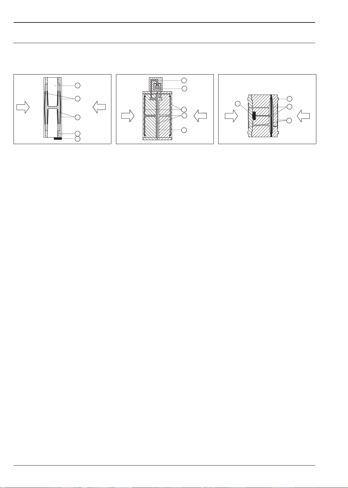
Measuring principle
Deltabar S
Ceramic measuring diaphragms used for PMD 70 and FMD 76
1
2
p
1
3
4
5
P01-xMD7xxxx-03-xx-xx-xx-000
Ceramic measuring cell PMD 70 and FMD 76
1 Meter body
2Diaphragm
3 Electrodes
4 Glass frit fixes the diaphragm onto the meter
body
5 Temperature sensor
p
2
Ceramic measuring diaphragms used for PMD 70 and FMD 76
The ceramic measuring cell is based on the principle of a plate capacitor with an electrode on (1) and a movable
electrode on the interior of the diaphragm (3). Standard silicone oil or mineral oil filling oils for this measuring
cell.
A differential pressure (p
are converted and are fed to the microprocessor of the transmitter as a digital signal.
Advantages:
• Self-monitoring for diaphragm break or oil loss (constant comparison of the measured temperature with a
temperature calculated from the capacitance values)
• Extremely high resistance to aggressive media
• Suitable for vacuums up to 0.02 psi
• Metal-free versions available
• Secondary process barrier for enhanced mechanical integrity
Metallic measuring diaphragms used for PMD 75, FMD 77 and FMD 78
1
2
6
5
P01-xMD7xxxx-03-xx-xx-xx-002
(1 mbar
abs
3
p
4
2
)
abs
p
1
Metal measuring cell for 40 inH2O (100 mbar) and
above
6 Sensing element
7 Overload diaphragm/Middle diaphragm
8 Filling oil
9 Separating diaphragm
p
1
Metal measuring cell 4 inH2O (10 mbar) and
12 inH
O (30 mbar)
2
1 Sensing element
2 Silicon diaphragm
3 Separating diaphragm
4 Filling oil
5 Integrated overload protection
≠ p2) causes a corresponding deflection of both diaphragms. Both capacitance values
1
7
8
p
2
9
P01-xMD7xxxx-03-xx -xx-xx-003
Metallic measuring diaphragms used for PMD 75, FMD 77 and FMD 78
The separating diaphragms (3/9) are deflected on both sides by the acting pressures. A filling oil (4/8) transfers
the pressure to a resistance circuit bridge (semi-conductor technology). The change due to differential pressure
of the bridge output voltage is measured and further processed.
Advantages:
• Standard operating pressures: 2320 psi and 6100 psi (160 bar and 420 bar)
• High long-term stability
• Very high single-sided overload resistance
• Secondary process barrier for enhanced mechanical integrity
6 Endress+Hauser
Deltabar S
Flow measurement Design and operation mode
++
Dp
p
p
2
1
Dp
Q~
Q
Flow measurement with Deltabar S and primary element, left: Orifice plate and right: Pitot tube
QFlow
∆
p Differential pressure, ∆p = p1 – p
2
Q~
Q
––
p
p
1
2
P01-PMD7xxxx-15-xx-xx-xx-000
Your benefits
• Choice of four flow modes of operation: volume flow, norm volume flow (European norm conditions),
standard volume flow (American standard conditions) and mass flow.
• Choice of flow units with automatic unit conversion.
• User-specified custom measuring units.
• Low flow cut off: when activated, this function suppresses small flows which can lead to large fluctuations
in the measured value.
• Contains two totalizers as standard. One totalizer is user-resettable.
• The totalizing mode and unit can be individually set for each totalizer. This allows independent daily and
annual quantity totalizing.
Endress+Hauser 7

Deltabar S
Level measurement (level, volume and mass)
Design and operation mode
–
–
h=
Dp
r g
1
h
2
+
3
+
P01xMD7xxxx-15-xx-xx-xx-000
Level measurement with Deltabar S
1 Level measurement via impulse piping and PMD 70
2 Level measurement with FMD 76
3 Level measurement via capillaries and FMD 78
h Height (level)
∆
p Differential pressure
ρ
Density of the medium
g Gravitation constant
Your benefits
• Choice of three level operating modes
• Volume and mass measurements in any tank shape by means of a freely programmable characteristic curve
• Choice of level units with automatic unit conversion
• User-specified custom measuring units
• Has a wide range of uses, e.g.
– for level measurement in tanks with static pressure
– in the event of foam formation
– in tanks with agitators of screen fittings
– in the event of liquid gases
– for standard level measurement
Communication protocol
• 4 to 20 mA with HART communication protocol
• PROFIBUS-PA
– The Endress+Hauser Deltabar S devices meet the requirements as per the FISCO model.
– Due to the low current consumption of 12 mA
– up to 9 Deltabar S for EEx ia, CSA IS and FM IS applications
– up to 32 Deltabar S for all other applications, e.g. in non-hazardous areas, EEx nA, etc.
can be operated at one bus segment with installation as per FISCO.
Further information on PROFIBUS-PA, such as requirements for bus system components, can be found in
the Operating Instructions BA 198F "PROFIBUS-DP/-PA: Guidelines for planning and commissioning" and
in the PNO guideline.
• Foundation Fieldbus
– The Endress+Hauser Deltabar S devices meet the requirements as per the FISCO model.
– Due to the low current consumption of 12 mA
– up to 9 Deltabar S for EEx ia, CSA IS and FM IS applications
– up to 32 Deltabar S for all other applications, e.g. in non-hazardous areas, EEx nA, etc.
can be operated on one bus segment with installation as per FISCO.
Further information on Foundation Fieldbus, such as requirements for bus system components, can be found
in the Operating Instructions BA 013S "Foundation Fieldbus Overview".
8 Endress+Hauser
Deltabar S
Human interface
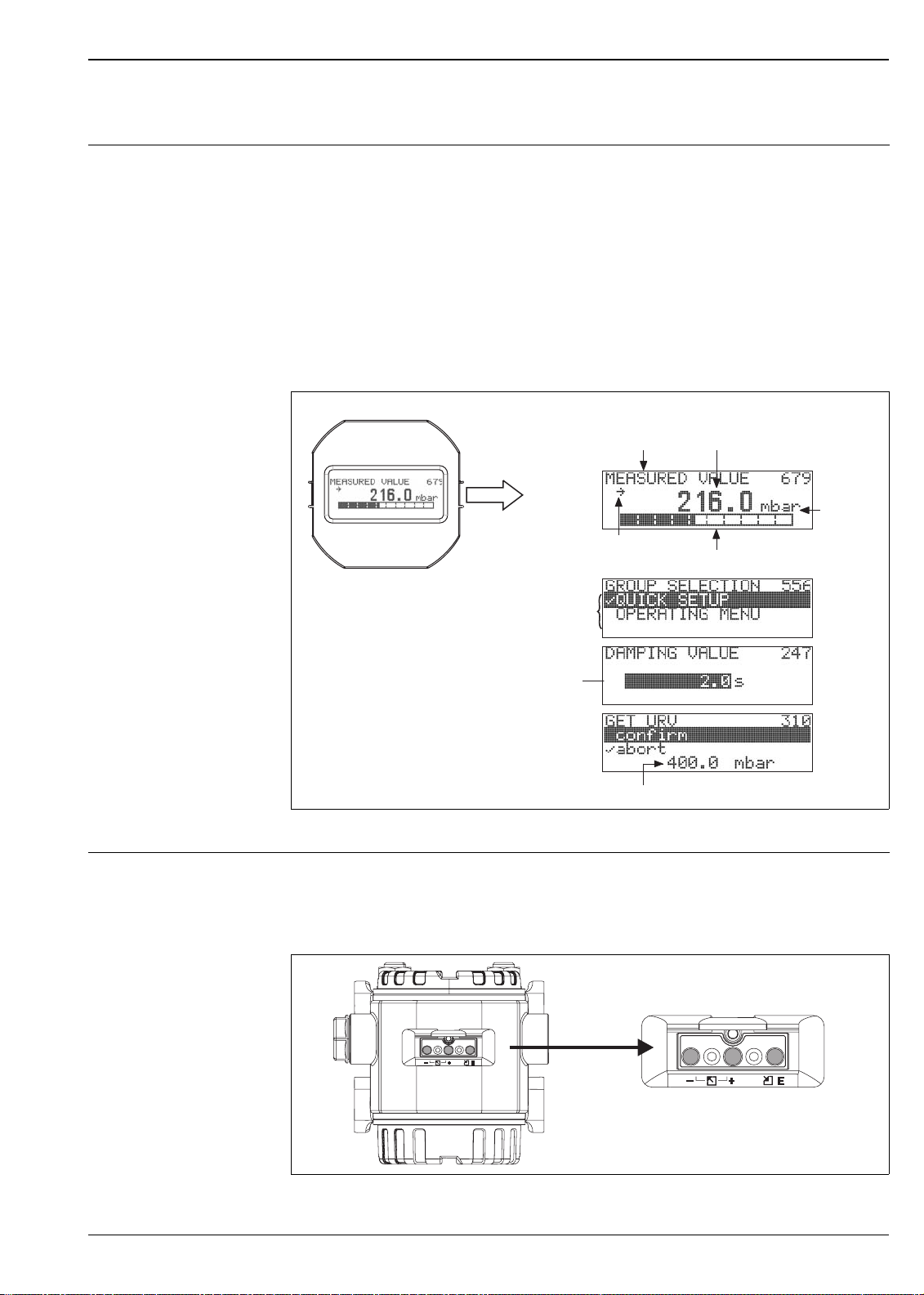
Display module (optional) A 4-line liquid crystal display (LCD) is used for display and operation. The display module shows measured
values, dialog text as well as fault and notice messages in plain text, thereby supporting the user in every stage
of operation.
Functions:
• 8-digit measured value display including sign and decimal point, bargraph for current display
• Simple and complete menu guidance due to separation of the parameters into three levels (blocks, groups
and functions)
• Each parameter is given a 3-digit ID number for easy navigation.
• Option for configuring the display according to individual requirements and desires, such as language,
alternating display, display of other measured values such as sensor temperature, contrast setting
• Comprehensive diagnostic functions (fault and warning message, peak-hold indicators, etc.)
• 4 to 20 mA HART: rapid and safe commissioning with the Quick Setup menus
Measured value display
Identification
number
Unit
Header line
Main line
Information
line
Function name Value
Symbol
Editing modes
Bargraph
Selection
option
Edit value
Current measured value
P01-xMD7xxxx-07-xx-xx-xx-000
Operating elements The operating buttons are located either under the protective cap on the exterior of the device or inside on the
electronic insert, depending on configuration of transmitter.
Operating buttons on the exterior of the device
P01-xxxxxxxx-19-xx-xx-xx-038
Endress+Hauser 9
Deltabar S
The operating buttons located externally on the device work on the Hall sensor principle. This guarantees the
following advantages:
• Complete protection against environmental influences such as moisture and contamination
• Simple operation without any tools
• No wear
Note!
With the "External push buttons" option, a display module is always purchased. → See also page 53 ff, feature
20 "Electronics, communication, display, operation".
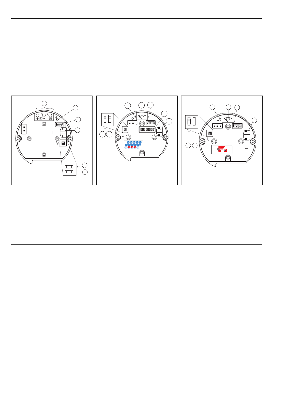
Operating keys and elements located internally on the electronic insert
1
2
3
4
PC
21
on
Sensor
Display
Histo
Damping
ROM
[]
off
5
t
6
onoff
P01-xxxxxxxx-19-xx-xx-xx-074
Electronic insert HART
1 Operating keys
2 Green LED to indicate acceptance of value
3 Slot for optional display
4 Slot for optional HistoROM
M-DAT
5 DIP-switch for locking/unlocking measured-
value parameters
6 DIP-switch for damping on/off
®
HistoROM
/M-DAT
(optional)
®
/
HistoROM®/M-DAT is a memory module, which is attached to the electronic insert. The HistoROM®/M-DAT
can be retrofitted into an existing transmitter.
2
0%
Zero
21
345 678
01
3
12
Address
3
Display
HW
CKON
SDA08
PC
5
678
SW
4
ROM
Histo
P01-xxxxxxxx-19-xx-xx-xx-075
4
5
1
off
on
2
1
7
6
on on
21
off off
Sensor
Electronic insert PROFIBUS PA
1 Green LED to indicate acceptance of value
2 Key for position calibration
3 Slot for optional display
4 Slot for optional HistoROM
®
/
M-DAT
5 DIP-switch for hardware address
6 DIP-switch without function
7 DIP-switch for locking/unlocking measured-
value parameters
Sensor
on
off
F
OUNDATION
2
0%
Zero
01
3
Display
P01-xxxxxxxx-19-xx-xx-xx-054
4
HW
PC
ROM
Histo
5
1
off
on
2
Simulation
6
1
21
Simulation
Electronic insert Foundation Fieldbus
1 Green LED to indicate acceptance of value
2 Key for position calibration
3 Slot for optional display
4 Slot for optional HistoROM
®
/
M-DAT
5 DIP-switch for simulation mode
6 DIP-switch for locking/unlocking measured-
value parameters
Your benefits
• Quick and safe commissioning of the same measuring points by copying the configuration data of one
transmitter to another transmitter
• Reliable process monitoring due to cyclical recording of pressure and sensor temperature measured values
• Simple diagnosis by recording events such as alarms, maximum indicators, counters for measuring
excursions outside user-specified pressure and temperature limits
• Analysis and graphic evaluation of the events and process parameters via ToF Tool (contained in scope of
supply)
®
HistoROM
/M-DAT can be ordered via feature 100 "Additional options 1" or feature 110 "Additional options
2". → See also page 53 ff.
10 Endress+Hauser

Deltabar S
Local operation Functions 4 to 20 mA HART
• With display module: navigate through the operating menu using three operating buttons
• Without display module:
– Position calibration (zero point correction)
– Setting lower-range value and upper-range value – reference pressure present at device
– Value acceptance indicated by green LED
• Device reset
• Locking and unlocking measured-value parameters
• Switching damping on and off
Functions PROFIBUS-PA
• Position calibration (zero point correction)
• Value acceptance indicated by green LED
• Locking and unlocking measured-value parameters
• Setting hardware address
Functions Foundation Fieldbus
• Position calibration (zero point correction)
• Value acceptance indicated by green LED
• Locking and unlocking measured-value parameters
• Switching simulation mode on and off
Handheld terminals – HART With a handheld terminal, all the parameters can be configured anywhere along the 4 to 20 mA line via menu
operation.
ToF Tool – HART, PROFIBUS PA
The ToF Tool is a graphic and menu-guided operating program for measuring devices from
Endress+Hauser. It is used for supporting the commissioning, data storage, signal analysis and documentation
of the devices. The following operating systems are supported: Win95, Win98, WinNT4.0, Win2000 and
Windows XP. You can set all parameters via the ToF Tool.
The ToF Tool supports the following functions:
Configuration of transmitters in online operation
•
• Loading and saving device data (upload/download)
• HistoROM
®
/M-DAT analysis
• Documentation of the measuring point
Connection options:
• HART via Commubox FXA 191 and the serial interface RS 232 C of a computer
• PROFIBUS-PA via segment coupler and PROFIBUS interface card
• Service interface with adapter FXA 193
Commuwin II – HART, PROFIBUS-PA
Commuwin II is a graphically supported operating program for intelligent measuring devices with the
communication protocols HART and PROFIBUS-PA. The following operating systems are supported: Win 3.1/
3.11, Win 95, Win 98, WinNT4.0 and Win2000. Commuwin II displays the most important parameters.
Commuwin II supports the following functions:
• Configuration of measuring devices in online operation via matrix operation
• Loading and saving device data (upload/download)
• Visualization of measured and limit values
• Presentation and recording of measured values with a line recorder.
Connection option:
• HART via Commubox FXA 191 and the serial interface RS 232 C of a computer
• PROFIBUS PA via segment coupler and PROFIBUS interface card
Remote operation – Foundation Fieldbus
An FF configuration program is required to integrate a device with "Foundation Fieldbus signal" into an FF
network or to set the FF-specific parameters. Please contact your local Endress+Hauser Sales for more
information.
Endress+Hauser 11

Deltabar S
Input
Measured variable Differential pressure, from which flow (volume or mass current) and level (level, volume or mass) are derived
Measuring range PMD 75, FMD 77, FMD 78 (with metallic measuring diaphragms)
7
7
2
sides
3480
(240)
3480
(240)
3480/9140
(240/630)
3480/9140
(240/630)
3480/9140
(240/630)
3480/9140
(240/630)
8
min.
operating
3
pressure
abs
0.001 (0.1) 7B –
7
0.001 (0.1) 7C –
7
0.001 (0.1) 7F 8F
0.001 (0.1) 7H 8H
0.001 (0.1) 7L 8L
0.001 (0.1) 7M 8M
Versions in the order
4
code
2320 psi
(PN 160)
6100 psi
6
(PN 420)
6
]
Nominal
Measurement limit Span MWP 1 Overload
value
lower (LRL) upper
(URL)
recommended
minimum
5
on one side on both
min./max.
psi [mbar] psi [mbar] psi [mbar] psi [mbar] psi [mbar] psi [bar] psi [bar] psi [bar] psi [mbar
4 inH
O
(10)
12 inH
(30)
40 inH
(100)
200 inH
(500)
O
2
O
2
O
2
(-10)
-12 inH2O
(-30)
-40 inH2O
(-100)
-200 inH2O
(-500)
-4 inH2O
2
43 (3000) -43
(-3000)
232
(16,000)
580
(40,000)
-232
(-16,000)
-580
(-40,000)
+4 inH2O
4 inH2O (10) 0.1 inH2O
(+10)
+12 inH2O
12 inH2O (30) 0.12 inH2O
(+30)
+40 inH2O
(+100)
+200 inH2O
(+500)
10/40 inH2O
(25/100)
13/200 inH2O
(33/500)
43 (+3000) 3/43
(200/3000)
+232
(+16,000)
+580
(+40,000)
15/232
1066/16,000
38/580
(2666/40,000)
(0.25)
(0.3)
2320
(160)
2320
(160)
2320
7
(160)
2320
7
(160)
0.4 inH2O (1) 2320 (160) 2320 (160) 3480 (240) 0.001 (0.1) 7D –
2 inH2O (5) 2320/6100
(160/420)
0.4 (30) 2320/6100
(160/420)
2 (160) 2320/6100
(160/420)
6 (400) 2320/6100
(160/420)
2320/6100
(160/420)
2320/6100
(160/420)
2320/6100
(160/420)
"+"side:
2320/6100
(160/420)
1) MWP = Maximum working pressure. → See also page 26, section "Pressure specifications".
2) FMD 77, FMD 78: The maximum pressure for the measuring device is dependent on the lowest-rated element, with regard to pressure, of the
selected components. → See also page 26, section "Pressure specifications".
3) The specified minimum operating pressure applies to the PMD 75 at the reference operating conditions for silicone oil. Min. operating
pressure at 185°F (85°C) for silicone oil: 0.145 psi
must also be observed for the FMD 77 and FMD 78. → See also page 46, section "Diaphragm seal filling oils".
(10 mbar
abs
). The pressure and temperature application limits of the selected filling oil
abs
4) Versions in the order code → See also page 53 ff, feature 40 "Measuring cell, nominal operating range, PN"
5) Minimum span that can be calibrated, turn down > 100:1 on request
6) 2320 psi (PN 160) versions with stainless steel M12 bolts, 6100 psi (PN 420) versions with steel M12 bolts, surface coating GEOMET
7) With copper seal: "MWP": max. 1450 psi (100 bar); "Overload on one side" and "Overload on both sides": max. 2175 psi (150 bar)
8) "–"side: 1450 psi (100 bar)
12 Endress+Hauser
Deltabar S
PMD 70, FMD 76 (with ceramic measuring diaphragms)
Nominal
Measurement limit Span MWP
1
Overload
value
lower (LRL) upper (URL) recom-
minimum
5
on one side on both
mended
min./max.
inH
O
2
[mbar]
inH2O [mbar] inH2O
[mbar]
inH2O [mbar] inH2O [mbar] psi [bar] psi [bar] psi [bar] psi [mbar
10 (25) -10 (25) +10 (+25) 10 (25) 0.1 (0.25) 145 (10) 145 (10) 217 (15) 14 (1) 7B
40 (100) -40 (-100) +40 (+100) 10/40 (25/100) 0.4 (1) 232 (16) 232 (16) 348 (24) 14 (1) 7D
200 (500) -200 (-500) +200 (+500) 13/200 (33/500) 2 (5) 1450 (100) 1450 (100) 2175 (150) 14 (1) 7F
1200 (3000) -1200 (-3000) +1200
(+3000)
80/1200
(200/3000)
12 (30) 1450 (100) 1450 (100) 2175 (150) 14 (1) 7H
1) MWP = Maximum working pressure. → See also page 26, section "Pressure specifications".
2) The specified overload only applies to the measuring cell. The maximum pressure for the measuring device is dependent on the weakest element,
with regard to pressure, of the selected components. → See also page 26, section "Pressure specifications".
3) Min. operating pressure at the reference operating conditions for silicone oil. Min. operating pressure at 185°F (85°C): to 0.145 psi
4) Versions in the order code → See also page 53 ff, feature 40 "Measuring cell, nominal operating range, PN"
5) Minimum span that can be calibrated, turn down > 100:1 on request
2
Min.
operating
pressure
3
Versions in the
order code
4
sides
]
abs
(10 mbar abs)
abs
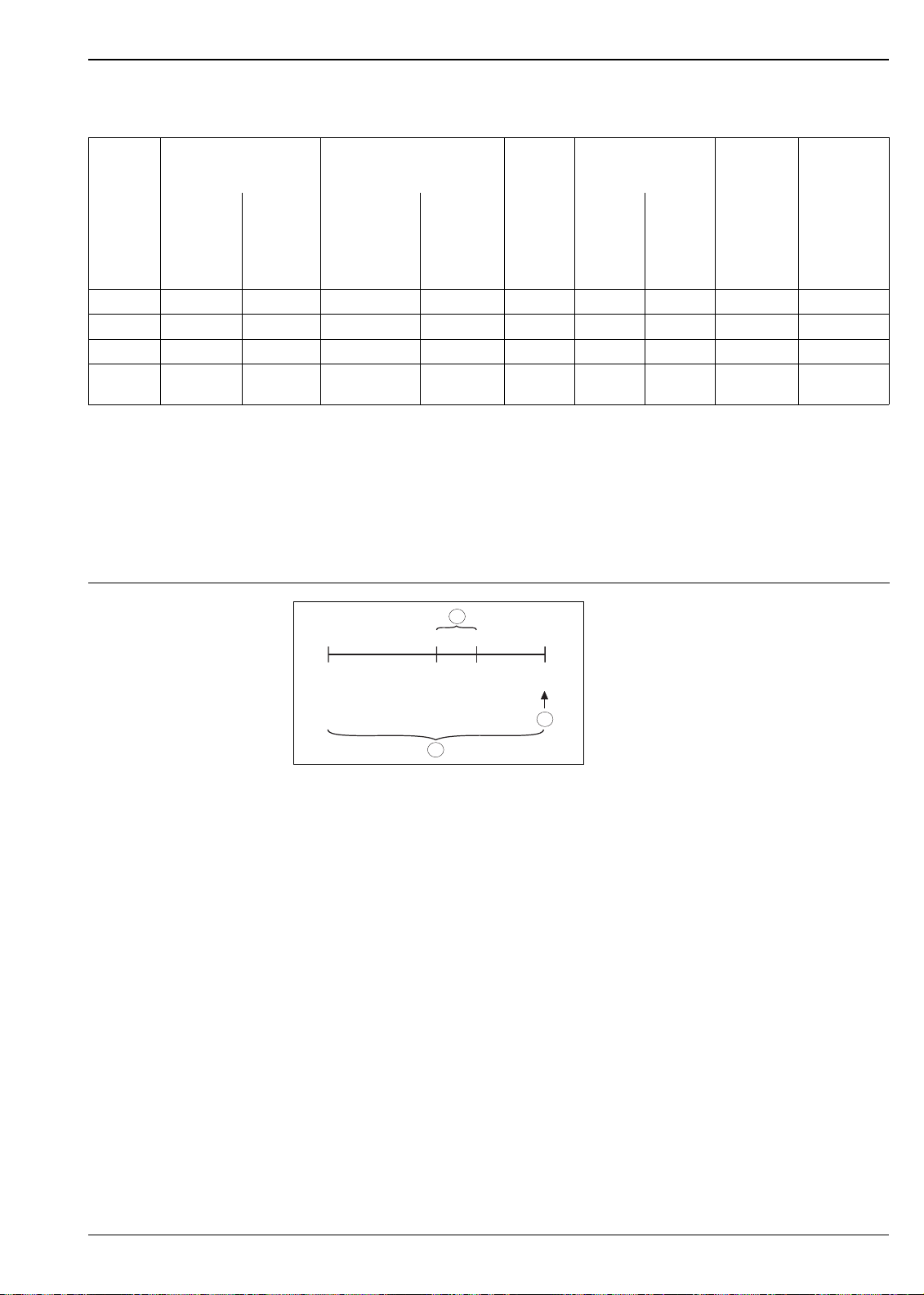
Explanation of terms
1
LRV
0
(40 inH O)
3
URV
100
LRL
–500 mbar
(-200 inH O)
2
Example: 200 inH2O (500 mbar) sensor
1Set span
2Nominal value
i
Upper range limit (URL)
3 Nominal measuring range
LRL Lower range limit
URL Upper range limit
LRV Lower range value
URV Upper range value
URL
+ 500 mbar
(+200 inH O)
2
2
P01-xxxxxxxx-05-xx-xx-xx-001
2
Explanation of the term 'Turn down (TD)'
(TD = turn down)
Turn down = nominal value/set span
Example:
Nominal value = 200 inH
Set span = 40 inH
TD = 5:1
O (500 mbar)
2
O (100 mbar)
2
Endress+Hauser 13
Output
Output signal • 4 to 20 mA with superimposed digital communication protocol HART, 2-wire
• Digital communication signal PROFIBUS-PA (Profile 3.0)
• Digital communication signal Foundation Fieldbus
Deltabar S
Signal on alarm
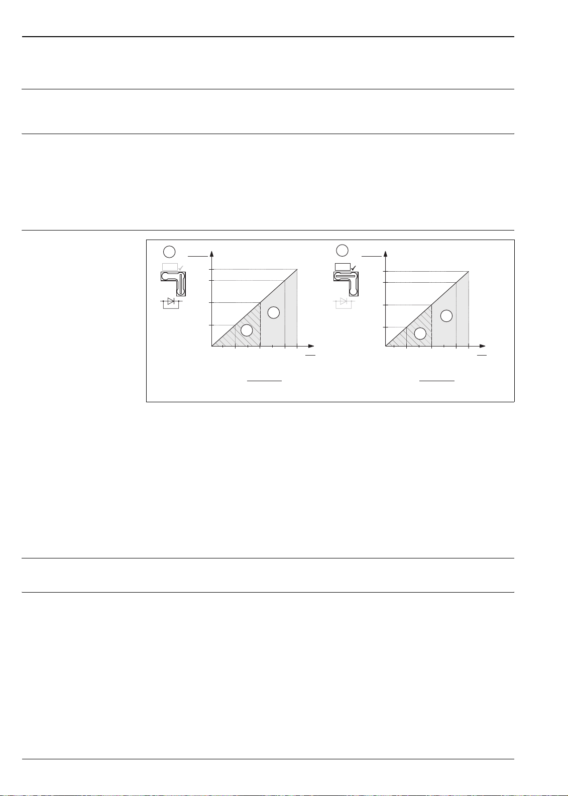
Load – 4 to 20 mA HART
• 4 to 20 mA HART
Options:
– Max. alarm*: can be set from 21 to 23 mA
– Keep measured value: last measured value is kept
– Min. alarm: 3.6 mA
* Factory setting: 22 mA
• PROFIBUS-PA: can be set in the Analog Input block, options: good, bad, uncertain
• Foundation Fieldbus: can be set, options: good, bad, uncertain
R
1
L
max
[]W
1500
1282
847
4
413
10.5
Load diagram, observe the position of the jumper and the explosion protection (→ See also page 16, section "Measuring 4
to 20 mA test signal".)
1 Jumper for 4 to 20 mA test signal inserted in "Standard" position
2 Jumper for 4 to 20 mA test signal inserted in "Test" position
3 Supply voltage 10.5 (11.5) to 30 V DC for EEx ia, 1/2 D, 1 GD, 1/2 GD, FM IS and CSA IS
4 Supply voltage 10.5 (11.5) to 45 V DC for device for non-hazardous areas, 1/3 D, EEx d, EEx nA, FM XP, FM DIP,
FM NI, CSA XP and CSA Dust-Ex
Maximum load resistance
R
Lmax
U Supply voltage
3
40 45
[V]
U
30
20
U – 10.5 V
R
£
L
max
23 mA
R
2
L
max
TestTest
[]W
1456
1239
804
4
369
11.5
3
30
20
U – 11.5 V
R
£
L
max
23 mA
U
40 45
[V]
P01-xMD7xxxx-05-xx-xx-xx-000
Note!
When operating via a handheld terminal or via PC with an operating program, a minimum communication
resistance of 250 Ω must exist within the loop.
Resolution
• Current output: 1 µA
• Display: can be set (setting at the factory: presentation of the maximum accuracy of the transmitter)
Reading cycle
• HART commands: on average 3 to 4 per second
• PROFIBUS-PA:
– cyclic: on average 100/s
– acyclic: on average 20/s
• Foundation Fieldbus:
– cyclic up to 5/s, dependent on the number and type of function blocks used in a closed-control loop
– acyclic: 10/s
14 Endress+Hauser
Deltabar S
Damping • Via display module, handheld terminal or PC with operating program, continuous from 0...999 s
• Additionally for HART: via DIP-switch on the electronic insert, switch position "On = set value" and "Off"
• Factory setting: 2 s
Power supply
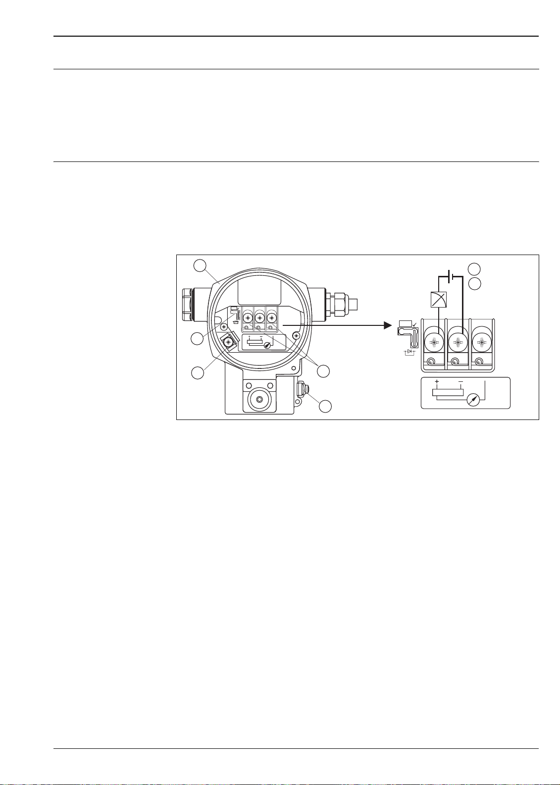
Electrical connection Note!
• When using the measuring device in hazardous areas, installation must comply with the corresponding
national standards and regulations and the Safety Instructions (XAs) or Installation or Control Drawings
(ZDs). → See also page 67, section "Safety Instructions" and "Installation/Control Drawings".
• Protective circuits against reverse polarity, HF influences and overvoltage peaks are installed.
4 to 20 mA HART
1
Test
2
3
4... 20mA
Test
5
4to20mA
Test
4 to 20mA
4
Electrical connection 4 to 20 mA HART
1Housing
2 Jumper for 4 to 20 mA test signal.
→ See also page 16, section "Measuring 4 to 20 mA" .
3 Internal ground terminal
4 External ground terminal
5 4 to 20 mA test signal between positive and test terminal
6 Minimum supply voltage = 10.5 V DC, jumper is inserted in accordance with the illustration.
7 Minimum supply voltage = 11.5 V DC, jumper is inserted in "Test" position.
PROFIBUS PA
The two-wire cable must be connected to the "PA+" and "PA–" terminals.
10.5 V DC
6
11.5 V DC
7
Test
P01-xMx7xxxx-04-xx-xx-xx-001
Foundation Fieldbus
The two-wire cable must be connected to the "FF+" and "FF–" terminals.
Endress+Hauser 15

Deltabar S
Measuring 4 to 20 mA test signal
A 4 to 20 mA signal may be measured via the positive and test terminal without interrupting the measurement.
The minimum supply voltage of the device can be reduced by simply changing the position of the jumper. As
a result, operation is also possible with lower voltage sources. Observe the position of the jumper in accordance
with the following table.
Jumper position for test signal Description
Test
– Measuring 4 to 20 mA test signal via plus and test terminal:
not possible.
– Delivery status
– minimum supply voltage: 10.5 V DC
Supply voltage Note!
• When using the measuring device in hazardous areas, installation must comply with the corresponding
national standards and regulations and the Safety Instructions (XAs) or Installation or Control Drawings
(ZDs).
• All explosion protection data are given in separate documentation which is available upon request. The Ex
documentation is supplied as standard with all devices approved for use in explosion hazardous areas. → See
also page 67, sections "Safety Instructions" and "Installation/Control drawing".
4 to 20 mA HART
• Version for non-hazardous areas, jumper for 4 to 20 mA test signal in "Standard" position: 10.5 to 45 V DC
• Version for non-hazardous areas, jumper for 4 to 20 mA test signal in "Test" position:
11.5 to 45 V DC
PROFIBUS-PA
Version for non-hazardous areas: 9 to 32 V DC
Foundation Fieldbus
Version for non-hazardous areas: 9 to 32 V DC
Test
– Measuring 4 to 20 mA test signal via plus and test terminal:
possible. (Thus, the output current can be measured without
interruption via the diode.)
– minimum supply voltage: 11.5 V DC
Current consumption
• PROFIBUS-PA: 11 mA ± 1 mA, switch-on current corresponds to table 4, IEC 61158-2
• Foundation Fieldbus: 11 mA ± 1 mA, switch-on current corresponds to table 4, IEC 61158-2
Cable entry → See also page 53 ff , feature 30 "Housing, Cable entry, Protection".
Cable specification
• Endress+Hauser recommends using shielded, twisted-pair two-wire cables.
• Terminals for wire cross-sections 0.5 to 2.5 mm
2
• Cable external diameter: 5 to 10 mm
Residual ripple Without influence on 4 to 20 mA signal up to ± 5 % residual ripple within the permitted voltage range
[according to HART hardware specification HCF_SPEC-54 (DIN IEC 60381-1)]
Influence of power supply ≤ 0.0006% of URL/1 V
16 Endress+Hauser

Deltabar S
Performance characteristics – general
Reference operating conditions • As per IEC 60770
• Ambient temperature T
• Humidity ϕ = constant, in the range of: 45 to 75 % r.H
• Ambient pressure p
• Position of the measuring cell: constant, in the range of: ±1°
• Input of LOW SENSOR TRIM and HIGH SENSOR TRIM for lower range value and upper range value
• Zero based span
• Membrane material PMD 75, FMD 77, FMD 78: AISI 316L
• Membrane material PMD 70, FMD 76: Al
• Filling oil: silicone oil
= constant, in the range of: +69.8 to +91.4°F (+21 to +33°C)
U
= constant, in the range of: 12 to 15 psi (860 to 1060 mbar)
U
(Aluminum oxide ceramic)
2O3
Long-term stability Measuring cells ≥ 200 inH
O (500 mbar):
2
• ±0.05% of URL/year
• ±0.125% of URL/5 years
Measuring cells ≤ 40 inH
O (100 mbar):
2
• ±0.18% of URL/year
Influence of the installation position
Vibration effects PMD 70, PMD 75: ≤ Reference accuracy to 15 to 25 Hz: 1.6 mm; 25 to 1000 Hz: 4g
Position-dependent zero shift can be corrected. → See also page 21, section "General installation instructions"
and page 50 ff, section "Installation instructions, Diaphragm seal systems".
Performance characteristics – metallic diaphragms
Reference accuracy – PMD 75, FMD 77, FMD 78
The reference accuracy comprises the non-linearity including hysteresis and non-reproducibility in accordance
with the limit point method as per IEC 60770.
PMD 75
O (10 mbar), 12 inH2O (30 mbar) measuring cells:
4 inH
2
• TD 1:1: ±0.15% of URV
• TD > 1:1: ±0.15% of URV x TD
O (100 mbar) measuring cell:
40 in H
2
• TD 1:1 to TD 4:1: ±0.075% [±0.05%] of URV
• TD > 4:1: ±(0.012 • TD + 0.027)% of URV
Measuring cells ≥ 200 inH
O (500 mbar):
2
• TD 1:1 to TD 15:1: ±0.075% [±0.05%] of URV
• TD > 15:1: ±(0.0015 • TD + 0.05252)% of URV
FMD 77, FMD 78
O (100 mbar) measuring cell:
40 in H
2
• TD 1:1 to TD 4:1: ±0.075% of URV + influence from the diaphragm seal
• TD > 4:1: ±(0.012 • TD + 0.027)% of URV + influence from the diaphragm seal
Measuring cells ≥ 200 inH
O (500 mbar):
2
• TD 1:1 bis TD 15:1: ±0.075% of URV + influence from the diaphragm seal
• TD > 15:1: ±(0.0015 • TD + 0.05252)% of URV + influence from the diaphragm seal
– Values in brackets [ ] for devices with improved reference accuracy (PLATINUM version)
– The following applies for the root-extracting characteristic curve:
The accuracy data of the Deltabar S is taken into the accuracy calculation of the flow rate with a factor of 0.5.
Endress+Hauser 17

Deltabar S
Total performance – PMD 75
Warm-up period – PMD 75, FMD 77, FMD 78
Dynamic response time (T63) – PMD 75, FMD 77, FMD 78
The "Total performance" specification comprises the non-linearity including hysteresis, non-reproducibility, the
thermal change of the zero point as well as the influence of the line pressure (p
• ±0.15% of URV
1. For measuring ranges ≥ 200 inH2O (500 mbar) to TD 2:1
2. All specifications apply to the temperature range +14 to +140°F (–10 to +60°C).
1, 2
= 1015 psi / 70 bar).
st
5.4 s
I
100 %
63 %
t1t
2
Dynamic response time
Type Dead time t
PMD 75 45 ms • 12 inH2O (30 mbar) measuring cell: 200 ms
1
Time constant (T63), t
• 40 inH
• 200 inH
• 43 psi (3 bar) measuring cell: 40 ms
FMD 77, FMD 78 dependent on the diaphragm seal
t
O (100 mbar) measuring cell: 60 ms
2
O (500 mbar) measuring cell: 45 ms
2
P01-xxxxxxxx-05-xx-xx-xx-007
2
Influence of the operating pressure on zero point and span – PMD 75, FMD 77, FMD 78
Measuring cell 4 inH2O (10 mbar) 12 inH2O (30 mbar) 40 inH2O (100 mbar) 200 inH2O (500 mbar)
Influence of the
operating pressure
on the zero point
Influence of the
operating pressure
on the span
Measuring cell 45 psi (3 bar) 230 psi (16 bar) 600 psi (40 bar)
Influence of the
operating pressure on
the zero point
Influence of the
operating pressure on
the span
±0.15% of URL/
100 psi (7 bar)
±0.035% of URL/
100 psi (7 bar)
±0.075% of URL/
1015 psi (70 bar)
±0.14% of URL/
1015 psi (70 bar)
±0.35% of URL/
1015 psi (70 bar)
±0.14% of URL/
1015 psi (70 bar)
±0.075% of URL/
1015 psi (70 bar)
±0.14% of URL/
1015 psi (70 bar)
±0.15% of URL/
1015 psi (70 bar)
±0.14% of URL/
1015 psi (70 bar)
±0.075% of URL/
1015 psi (70 bar)
±0.14% of URL/
1015 psi (70 bar)
±0.075% of URL/
1015 psi (70 bar)
±0.14% of URL/
1015 psi (70 bar)
Note!
The influence of the operating pressure on the zero point can be calibrated out.
18 Endress+Hauser

Deltabar S
Thermal change of the zero
output and the output span –
PMD 75
Reference accuracy – PMD 70, FMD 76
+14 to +140°F (–10 to +60°C):
• 4, 12 inH
• 40 inH
• 200 inH
O (10 mbar, 30 mbar) measuring cell: ±(0.31 • TD + 0.06)% of URV
2
O (100 mbar) measuring cell: ±(0.18 • TD + 0.02)% of URV
2
O, 45 psi (500 mbar, 3 bar) measuring cell: ±(0.08 • TD + 0.05)% of URV
2
• 230 psi (16 bar) measuring cell: ±(0.1 • TD + 0.1)% of URV
• 600 psi (40 bar) measuring cell: ±(0.025 • TD + 0.05)% of URV
–40 to +14°F, +140 to +185°F (–40 to –10°C, +60 to +85°C):
• 4, 12 inH
• 40 inH
• 200 inH
O (10 mbar, 30 mbar) measuring cell: ±(0.45 • TD + 0.1)% of URV
2
O (100 mbar) measuring cell: ±(0.3 • TD + 0.15)% of URV
2
O, 45 psi (500 mbar, 3 bar) measuring cell: ±(0.12 • TD + 0.1)% of URV
2
• 230 psi (16 bar) measuring cell: ±(0.15 • TD + 0.2)% of URV
• 600 psi (40 bar) measuring cell: ±(0.37 • TD + 0.1)% of URV
Performance characteristics – ceramic diaphragms
The reference accuracy comprises the non-linearity including hysteresis and non-reproducibility in accordance
with the limit point method as per IEC 60770.
10 inH
O (25 mbar) measuring cell:
2
• TD 1:1: ±0.15% of URV
• TD > 1:1: ±0.15% of URV x TD
O (100 mbar) measuring cell:
40 inH
2
• TD 1:1 to TD 4:1: ±0.075% [±0.05%] of URV
• TD > 4:1: ±(0.012 • TD + 0.027)% of URV
200 inH
• TD 1:1 to TD 15:1: ±0.075% [±0.05%] of URV
• TD > 15:1: ±(0.0015 • TD + 0.05252)% of URV
O, 43 psi (500 mbar, 3 bar) measuring cell:
2
Total performance – PMD 70, FMD 76
Warm-up period – PMD 70, FMD 76
– Values in brackets [ ] for devices with improved reference accuracy (PLATINUM version)
– The following applies for the root-extracting characteristic curve:
The accuracy data of the Deltabar S is taken into the accuracy calculation of the flow rate with a factor of 0.5.
The "Total performance" specification comprises the non-linearity including hysteresis, non-reproducibility, the
thermal change of the zero point as well as the influence of the line pressure (p
• ±0.15% of URV
1. For measuring ranges ≥ 200 inH
2. All specifications apply to the temperature range +14 to +140°F (–10 to +60°C).
1, 2
O (500 mbar), TD 1:1
2
= 1015 psi / 70 bar).
st
5.4 s
Endress+Hauser 19

Deltabar S
Dynamic response time (T63) – PMD 70, FMD 76
Influence of the operating pressure on zero point and span – PMD 70, FMD 76
I
100 %
63 %
t1t
2
Dynamic response time
Type Dead time t
PMD 70, FMD 76 90 ms • 10 inH2O (25 mbar) measuring cell: 4700 ms
Measuring cell 10 inH2O (25 mbar) 40 inH2O (100 mbar) 200 inH2O (500 mbar) 45 psi (3 bar)
Influence of the
operating pressure
on the zero point
Influence of the
operating pressure
on the span
±0.7% of URL/
100 psi (7 bar)
±0.14% of URL/
1015 psi (70 bar)
1
±0.175% of URL/
100 psi (7 bar)
±0.14% of URL/
1015 psi (70 bar)
Time constant (T63), t
• 40 inH
•
O (100 mbar) measuring cell: 280 ms
2
200 inH2O (500 mbar) measuring cell: 210 ms
±0.075% of URL/
1015 psi (70 bar)
±0.14% of URL/
1015 psi (70 bar)
t
P01-xxxxxxxx-05-xx-xx-xx-007
2
±0.075% of URL/
1015 psi (70 bar)
±0.14% of URL/
1015 psi (70 bar)
Thermal change of the zero
output and the output span –
PMD 70, FMD 76
Note!
The influence of the operating pressure on the zero point can be calibrated out.
+14 to +140°F (–10 to +60°C):
• 10 inH
• ≥ 40 inH
O (25 mbar) measuring cell: ±(0.35 • TD + 0.05)% of URV
2
O (100 mbar) measuring cells: ±(0.05 • TD + 0.05)% of URV
2
–40 to +14°F, +140 to +185°F (–40 to –10°C, +60 to +85°C):
• 10 inH
• ≥ 40 inH
O (25 mbar) measuring cell: ±(0.3 • TD + 0.15)% of URV
2
O (100 mbar) measuring cells: ±(0.08 • TD + 0.07)% of URV
2
20 Endress+Hauser

Deltabar S
Operating conditions (installation)
General installation instructions • For FMD 77 and FMD 78: See page 50 ff, "Installation instructions, Diaphragm seal systems" section.
• The position-dependent zero shift can be corrected directly at the device via operating keys, even in
hazardous areas. Diaphragm seals also shift the zero point, depending on the installation position (→ See also
page 50 ff, "Installation instructions, Diaphragm seal systems").
• The housing of the Deltabar S can be rotated up to 380°. → See also page 22, section "Rotating the
housing".
• Endress+Hauser offers a mounting bracket for installing on pipes or walls. → See also page 22, section
"Wall- and pipe-mounting".
• When measuring in media with solid proportions, such as dirty liquids, installing separators and drain valves
is useful for capturing and removing sediment.
• Using a three-valve or five-valve manifold allows for easy commissioning, installation and maintenance
without interrupting the process.
• General recommendations for the impulse piping can be found in DIN 19210 "Methods for measurement of
fluid flow; differential piping for flow measurement devices" or the corresponding national or international
standards.
• Install the impulse piping with a continuous gradient of at least 10%.
• When routing the impulse piping outdoors, ensure that sufficient anti-freeze protection is used, e.g. by using
pipe heat tracing.
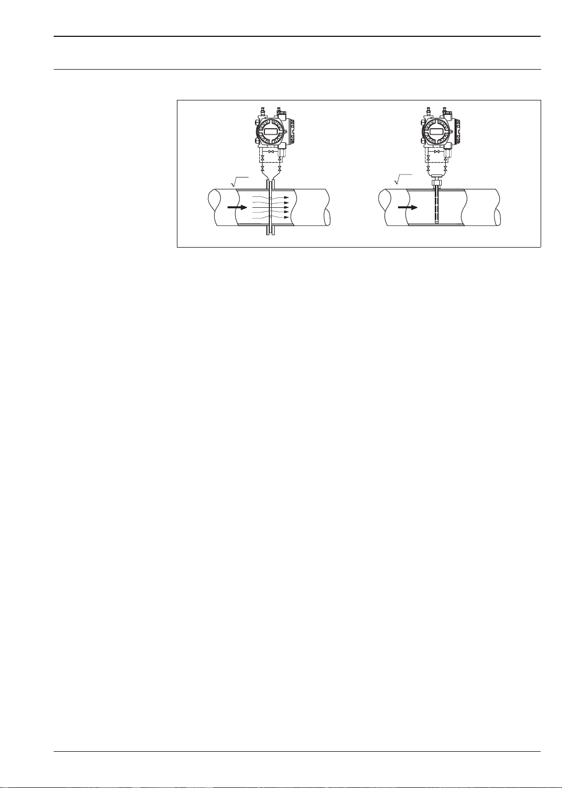
Measuring arrangement Flow measurement
• The PMD 70 and PMD 75 are best suited to flow measurement.
• Measuring arrangement for gases: Mount device above the measuring point.
• Measuring arrangement for liquids and steam: Mount device below tapping point.
• For flow measurement in steam, mount the condensate traps at the same level as the tapping point and at
the same distance from Deltabar S.
Level measurement
• PMD 70, PMD 75, FMD 76 and FMD 77 are best suited to level measurement in open tanks. All Deltabar
S devices are suitable for level measurement in closed tanks.
Measuring arrangement level measurement in open tanks
• PMD 70, PMD 75: Mount device below the lower measuring connection. The negative side is open to
atmosphere pressure.
• FMD 76, FMD 77: Mount device directly on the tank or with shut-off valve. The negative side is open to
atmospheric pressure.
Measuring arrangement level measurement in closed tanks and closed tanks with static pressure
• PMD 70, PMD 75: Mount device below the lower measuring connection. Always connect the negative side
above the maximum level.
• FMD 76, FMD 77: Mount device directy on the tank. Always connect the negative side above the maximum
level.
• In the case of level measurement in closed tanks with static pressure, a condensate trap ensures pressure
which remains constant on the minus side.
Pressure measurement
• The PMD 70 and PMD 75 are best suited to differential pressure measurement.
• Measuring arrangement for gases: Mount device above the measuring point.
• Measuring arrangement for liquids and steam: Mount device below tapping point.
• For differential pressure measurement in steam, mount the condensate traps at the same level as the tapping
point and at the same distance from Deltabar S.
Endress+Hauser 21
 Loading...