

Endress+Hauser Deltabar S FMD 77, Deltabar S FMD 78, Deltabar S FMD 76, Deltabar S PMD 75, Deltabar S PMD 70 Technical Information
Page 1

Technical Information
Deltabar S PMD 70/75, FMD 76/77/78
Differential pressure with ceramic and polysilicon sensors for flow,
level and differential measurement
High accuracy with excellent long-term stability
HART®, Foundation Fieldbus or PROFIBUS-PA protocols
PMD70
Applications
Deltabar S pressure transmitters are suitable for:
• Flow measurement (volumetric or mass flow) in
conjunction with primary elements in gas, steam
and liquid applications.
• Level, volume or mass measurement in liquids.
• Differential pressure monitoring, e.g. across filters or
pumps.
• Corrosive or abrasive applications using unique
ceramic sensor technology (PMD 70). For example,
DP measurement across a filter with abrasive
product.
• High temperatures up to 662°F (350°C) with
remote diaphragm seals (FMD 78).
Your benefits
Top of the line technical specifications:
• High long-term stability (0.05% of URL/year)
• High accuracy: up to ±0.075% span (< 15 : 1
turndown), with optional Platinum version (±0.05%
span)
• Turn down 100 : 1 standard, higher on request
Designed with safety in mind to keep your plant,
equipment and personnel safe:
• SIL-2 certificate optional
• Function-monitoring of the measuring cell by the
electronics provides alert upon sensor failure
PMD75
FMD76
FMD77 FMD78
• Secondary seals standard in every transmitter
• Built-in diagnostic software functionality (e.g.,
user-defined max/min operating window)
• Optional FM and CSA certificates, plus
combination certificates
Modular design for easy repair:
• Replaceable display
• Universal electronics for pressure and
differential pressure
Easy to setup with menu-driven interface, quick setup
menu for standard application modes:
• Pressure
• Level
• Flow
HistoROM/M-DAT memory module enables:
• Quick duplication of measuring points
• Process monitoring via periodic recording of
pressure and temperature values
• Monitoring of events and configuration changes
• Analysis and graphical evaluation of data by ToF tool
software
Flexible commissioning via multiple modes:
• On-board push buttons (external, or inside housing)
• HART® handheld operation
• ToF tool (PC software, free of charge with each
transmitter) plus HART modem
• PROFIBUS-PA or Foundation Fieldbus configuration
software
TI 382P/24/ae/04.04
Page 2

Table of contents
Deltabar S
Function and system design. . . . . . . . . . . . . . . . . . . . . . 4
Device selection . . . . . . . . . . . . . . . . . . . . . . . . . . . . . . . . . . . . . . 4
Overview of diaphragm seal FMD 78 . . . . . . . . . . . . . . . . . . . . . . 5
Measuring principle . . . . . . . . . . . . . . . . . . . . . . . . . . . . . . . . . . . 6
Flow measurement . . . . . . . . . . . . . . . . . . . . . . . . . . . . . . . . . . . . 7
Level measurement (level, volume and mass) . . . . . . . . . . . . . . . . 8
Communication protocol . . . . . . . . . . . . . . . . . . . . . . . . . . . . . . . 8
Human interface . . . . . . . . . . . . . . . . . . . . . . . . . . . . . . 9
Display module (optional) . . . . . . . . . . . . . . . . . . . . . . . . . . . . . . . 9
Operating elements . . . . . . . . . . . . . . . . . . . . . . . . . . . . . . . . . . . 9
HistoROM®/M-DAT (optional) . . . . . . . . . . . . . . . . . . . . . . . . . 10
Local operation . . . . . . . . . . . . . . . . . . . . . . . . . . . . . . . . . . . . . . 11
Handheld terminals – HART . . . . . . . . . . . . . . . . . . . . . . . . . . . . 11
ToF Tool – HART, PROFIBUS PA . . . . . . . . . . . . . . . . . . . . . . . . 11
Commuwin II – HART, PROFIBUS PA . . . . . . . . . . . . . . . . . . . . 11
Remote operation – Foundation Fieldbus . . . . . . . . . . . . . . . . . . 11
Input . . . . . . . . . . . . . . . . . . . . . . . . . . . . . . . . . . . . . 12
Measured variable . . . . . . . . . . . . . . . . . . . . . . . . . . . . . . . . . . . 12
Measuring range . . . . . . . . . . . . . . . . . . . . . . . . . . . . . . . . . . . . . 12
Explanation of terms . . . . . . . . . . . . . . . . . . . . . . . . . . . . . . . . . . 13
Output . . . . . . . . . . . . . . . . . . . . . . . . . . . . . . . . . . . . 14
Output signal . . . . . . . . . . . . . . . . . . . . . . . . . . . . . . . . . . . . . . . 14
Signal on alarm . . . . . . . . . . . . . . . . . . . . . . . . . . . . . . . . . . . . . 14
Load – 4 to 20 mA HART . . . . . . . . . . . . . . . . . . . . . . . . . . . . . . 14
Resolution . . . . . . . . . . . . . . . . . . . . . . . . . . . . . . . . . . . . . . . . . 14
Reading cycle . . . . . . . . . . . . . . . . . . . . . . . . . . . . . . . . . . . . . . . 14
Damping . . . . . . . . . . . . . . . . . . . . . . . . . . . . . . . . . . . . . . . . . . 15
Power supply . . . . . . . . . . . . . . . . . . . . . . . . . . . . . . . 15
Electrical connection . . . . . . . . . . . . . . . . . . . . . . . . . . . . . . . . . 15
Supply voltage . . . . . . . . . . . . . . . . . . . . . . . . . . . . . . . . . . . . . . 16
Current consumption . . . . . . . . . . . . . . . . . . . . . . . . . . . . . . . . . 16
Cable entry . . . . . . . . . . . . . . . . . . . . . . . . . . . . . . . . . . . . . . . . 16
Cable specification . . . . . . . . . . . . . . . . . . . . . . . . . . . . . . . . . . . 16
Residual ripple . . . . . . . . . . . . . . . . . . . . . . . . . . . . . . . . . . . . . . 16
Influence of power supply . . . . . . . . . . . . . . . . . . . . . . . . . . . . . . 16
Performance characteristics – general . . . . . . . . . . . . . 17
Reference operating conditions . . . . . . . . . . . . . . . . . . . . . . . . . . 17
Long-term stability . . . . . . . . . . . . . . . . . . . . . . . . . . . . . . . . . . . 17
Influence of the installation position . . . . . . . . . . . . . . . . . . . . . . 17
Vibration effects . . . . . . . . . . . . . . . . . . . . . . . . . . . . . . . . . . . . . 17
Performance characteristics –
ceramic diaphragms . . . . . . . . . . . . . . . . . . . . . . . . . . 19
Reference accuracy . . . . . . . . . . . . . . . . . . . . . . . . . . . . . . . . . . 19
Total performance. . . . . . . . . . . . . . . . . . . . . . . . . . . . . . . . . . . . 19
Warm-up period . . . . . . . . . . . . . . . . . . . . . . . . . . . . . . . . . . . . 19
Dynamic response time (T63) . . . . . . . . . . . . . . . . . . . . . . . . . . . 20
Influence of the operating pressure
on zero point and span . . . . . . . . . . . . . . . . . . . . . . . . . . . . . . . . 20
Thermal change of the
zero output and the output span . . . . . . . . . . . . . . . . . . . . . . . . . 20
Operating conditions (installation) . . . . . . . . . . . . . . . . 21
General installation instructions . . . . . . . . . . . . . . . . . . . . . . . . . 21
Measuring arrangement . . . . . . . . . . . . . . . . . . . . . . . . . . . . . . . 21
Wall- and pipe-mounting . . . . . . . . . . . . . . . . . . . . . . . . . . . . . . 22
Rotating the housing . . . . . . . . . . . . . . . . . . . . . . . . . . . . . . . . . 22
Oxygen applications . . . . . . . . . . . . . . . . . . . . . . . . . . . . . . . . . . 23
Ultra pure gas applications . . . . . . . . . . . . . . . . . . . . . . . . . . . . . 23
Diaphragms for materials with hydrogen build-up
(Rhodium-Gold coating) . . . . . . . . . . . . . . . . . . . . . . . . . . . . . . . 23
Operating conditions (Environment) . . . . . . . . . . . . . . 23
Ambient temperature range . . . . . . . . . . . . . . . . . . . . . . . . . . . . 23
Storage temperature range . . . . . . . . . . . . . . . . . . . . . . . . . . . . . 24
Degree of protection . . . . . . . . . . . . . . . . . . . . . . . . . . . . . . . . . 24
Climate class . . . . . . . . . . . . . . . . . . . . . . . . . . . . . . . . . . . . . . . 24
Vibration resistance . . . . . . . . . . . . . . . . . . . . . . . . . . . . . . . . . . 24
Electromagnetic compatibility . . . . . . . . . . . . . . . . . . . . . . . . . . 24
Overvoltage protection . . . . . . . . . . . . . . . . . . . . . . . . . . . . . . . . 24
Operating conditions (Process) . . . . . . . . . . . . . . . . . . 24
Process temperature limits . . . . . . . . . . . . . . . . . . . . . . . . . . . . . 24
Temperature operating range, seals . . . . . . . . . . . . . . . . . . . . . . 24
Pressure specifications . . . . . . . . . . . . . . . . . . . . . . . . . . . . . . . . 26
Mechanical construction . . . . . . . . . . . . . . . . . . . . . . . 26
Housing dimensions, optional display on the side (T14) . . . . . . . 26
Housing dimensions, optional display on the top (T15) . . . . . . . . 26
Process connections PMD 70 . . . . . . . . . . . . . . . . . . . . . . . . . . . 27
Process connections PMD 75 . . . . . . . . . . . . . . . . . . . . . . . . . . . 28
Process connection FMD 76 . . . . . . . . . . . . . . . . . . . . . . . . . . . . 31
Process connections FMD 77, low-pressure side . . . . . . . . . . . . . 33
Process connections FMD 77, high-pressure side . . . . . . . . . . . . 34
Process connection FMD 78 . . . . . . . . . . . . . . . . . . . . . . . . . . . . 37
Weight . . . . . . . . . . . . . . . . . . . . . . . . . . . . . . . . . . . . . . . . . . . 44
Material . . . . . . . . . . . . . . . . . . . . . . . . . . . . . . . . . . . . . . . . . . . 44
Performance characteristics –
metallic diaphragms . . . . . . . . . . . . . . . . . . . . . . . . . . 17
Reference accuracy . . . . . . . . . . . . . . . . . . . . . . . . . . . . . . . . . . . 17
Total performance . . . . . . . . . . . . . . . . . . . . . . . . . . . . . . . . . . . . 18
Warm-up period . . . . . . . . . . . . . . . . . . . . . . . . . . . . . . . . . . . . . 18
Dynamic response time (T63) . . . . . . . . . . . . . . . . . . . . . . . . . . . 18
Influence of the operating pressure
on zero point and span . . . . . . . . . . . . . . . . . . . . . . . . . . . . . . . . 18
Thermal change of the
zero output and the output span . . . . . . . . . . . . . . . . . . . . . . . . . 19
2 Endress+Hauser
Planning instructions, diaphragm seal systems . . . . . . . 45
Applications . . . . . . . . . . . . . . . . . . . . . . . . . . . . . . . . . . . . . . . . 45
Design and operation mode . . . . . . . . . . . . . . . . . . . . . . . . . . . . 45
Diaphragm seal filling oils . . . . . . . . . . . . . . . . . . . . . . . . . . . . . . 46
Influence of the temperature
on the zero point for diaphragm seal systems . . . . . . . . . . . . . . . 47
Ambient temperature range . . . . . . . . . . . . . . . . . . . . . . . . . . . . 49
Response time . . . . . . . . . . . . . . . . . . . . . . . . . . . . . . . . . . . . . . 49
Installation instructions . . . . . . . . . . . . . . . . . . . . . . . . . . . . . . . 50
Page 3

Certificates and approvals . . . . . . . . . . . . . . . . . . . . . . 52
CE mark . . . . . . . . . . . . . . . . . . . . . . . . . . . . . . . . . . . . . . . . . . 52
Hazardous area approvals . . . . . . . . . . . . . . . . . . . . . . . . . . . . . . 52
Pressure Equipment Directive (PED) . . . . . . . . . . . . . . . . . . . . . 52
Overspill protection . . . . . . . . . . . . . . . . . . . . . . . . . . . . . . . . . . 52
Standards and guidelines . . . . . . . . . . . . . . . . . . . . . . . . . . . . . . 52
Ordering information . . . . . . . . . . . . . . . . . . . . . . . . . 53
PMD 70 . . . . . . . . . . . . . . . . . . . . . . . . . . . . . . . . . . . . . . . . . . 53
PMD 75 . . . . . . . . . . . . . . . . . . . . . . . . . . . . . . . . . . . . . . . . . . 55
FMD 76 . . . . . . . . . . . . . . . . . . . . . . . . . . . . . . . . . . . . . . . . . . 58
FMD 77 . . . . . . . . . . . . . . . . . . . . . . . . . . . . . . . . . . . . . . . . . . 61
FMD 78 . . . . . . . . . . . . . . . . . . . . . . . . . . . . . . . . . . . . . . . . . . 64
Further documentation . . . . . . . . . . . . . . . . . . . . . . . . 67
Technical Information . . . . . . . . . . . . . . . . . . . . . . . . . . . . . . . . 67
Operating instructions . . . . . . . . . . . . . . . . . . . . . . . . . . . . . . . . 67
Safety Instructions . . . . . . . . . . . . . . . . . . . . . . . . . . . . . . . . . . . 67
Installation/Control Drawings . . . . . . . . . . . . . . . . . . . . . . . . . . 67
Overspill protection . . . . . . . . . . . . . . . . . . . . . . . . . . . . . . . . . . 67
Deltabar S
3 Endress+Hauser
Page 4

Device selection
–
Deltabar S
Function and system design
Deltabar S –
PMD 70
PMD 75
FMD 76
FMD 77
product family
+ –
P01-PMD70xxx-16-xx-xx-xx-000
With ceramic
measuring diaphragms
P01-PMD75xxx-16-xx-xx-xx-000
With metallic
measuring diaphragms
P01-FMD76xxx-16-xx-xx-xx-000
With ceramic
measuring diaphragms
With metallic
measuring diaphragms
and diaphragm seal
mounted on one side
Field of application – Flow
– Level
– Differential pressure
Process connections – 1/4 "– 18 NPT
–RC 1/4
Measuring ranges from -10 to +10 inH
(-25 to +25 mbar)
to -45 to +45 psi
(to -3 to +3 bar)
Overload
1
on one side: 1450 psi
(100 bar)
on both sides: 2175 psi
–Flow
– Level
– Differential pressure
– 1/4" – 18 NPT
–RC 1/4
O
from -0.4 to +0.4 inH
2
(-10 to +10 mbar)
to -600 to +600 psi
(-40 to +40 bar)
on one side:
max. 6100 psi
(max. 420 bar)
– Level – Level – Level
Low-pressure side (–):
– 1/4" – 18 NPT
–RC 1/4
High-pressure side (+):
– DN 80 – DN 100
–ANSI 3" – 4"
– JIS 80A – 100A
O
from -40 to +40 inH
2
(-100 to +100 mbar)
to to -45 to +45 psi
(-3 to +3 bar)
on one side:
max. 1450 psi
(max. 100 bar)
Low-pressure side (–):
– 1/4" – 18 NPT
–RC 1/4
High-pressure side (+):
– DN 50 – DN 100
– ANSI 2" – 4"
– JIS 80A – 100A
O
from -40 to +40 inH
2
(-100 to +100 mbar)
to -230 to +230 psi
(-16 bar to +16 bar)
on one side:
max. 2320 psi
(max. 160 bar)
(150 bar)
Process temperature –40 to +185°F
(–40 to +85°C)
Ambient temperature –40 to +185°F
(–40 to +85°C)
Reference Accuracy – Up to ±0.075% of the set span
–40 to +248°F
(–40 to +120°C)
–40 to +185°F
(–40 to +85°C)
–40 to +185°F
up to +662°F (+ 350°C) up to +662°F (+350°C)
(–40 to +85°C)
2
–40 to +185°F
(–40 to +85°C )
–40 to +185°F
(–40 to +85°C)
– Up to ±0.075 % of the set span + influence from
– PLATINUM version: up to ±0.05% of the set span
Supply voltage – For non-hazardous areas: 10.5 to 45 V DC
– Intrinsically safe (EEx ia): 10.5 to 30 V DC
Output 4 to 20 mA with superimposed HART protocol, PROFIBUS-PA or Foundation Fieldbus
Options – High-pressure version up to p
– PMD 75, FMD 77, FMD 78: Rhodium-Gold-coated diaphragm, NACE-compliant materials
Specialities
(options)
– Metal-free
measurement with
PVDF flange
10,000 psi (700 bar)
stat
up to 6100 psi
–p
stat
(420 bar)
– Diaphragm: tantalum
– Abrasion-resistant and
corrosion-resistant
– No diaphragm-seal
–For high media
temperature effects
– Metal-free
measurement possible
with ECTFE-coated
process connection
++–
P01-FMD77xxx-16-xx-xx-xx-000
2
the diaphragm seal
temperatures
FMD 78
P01-FMD78xxx-16-xx-xx-xx-003
With metallic
measuring diaphragms
and capillary diaphragm
seals
– Differential pressure
–Wide range of
diaphragm seals,
→ see page 5, section
"Overview of
diaphragm seal
FMD 78"
O
from - -40 to +40 inH
2
(-100 to +100 mbar)
to -600 to +600 psi
(-40 to +40 bar)
on one side:
max. 2320 psi
(max. 160 bar)
–40 to +185°F
(–40 to +85°C)
–Wide range of
diaphragm seals
O
2
2
1) dependent on the lowest-rated element, with regard to pressure, of the selected components
2) lower temperature on request
4 Endress+Hauser
Page 5

Deltabar S
Overview of diaphragm seal FMD 78
Design Diaphr. seal Connection Version Standard Nominal diameter Nom. press./Class
Cell Membrane
diaphragm seal
(MDM)
Threaded
connection with
separator
Membrane
diaphragm seal
(MDM)
Tri-Clamp Membrane
diaphragm seal
(MDM)
Pipe diaphragm
seal (RDM)
Hygienic
connections
Membrane
diaphragm seal
(MDM)
ANSI cell
DIN cell DIN 2501 – DN 50
P01-FMD78xxx-04-xx-xx-xx-000
NPT
P01-FMD78xxx-03-xx-xx-xx-011
G
P01-FMD78xxx-03-xx-xx-xx-010
Clamp
P01-FMD78xxx-03-xx-xx-xx-005
Clamp
P01-FMD78xxx-03-xx-xx-xx-009
Varivent
P01-FMD78xxx-03-xx-xx-xx-007
DRD
ANSI B 16.5 – 2"
150 to 2500 lb
–3"
–4"
PN 16 to 400
–DN 80
–DN 100
ANSI 1/2" NPT (inside) 600 psi
ISO 228 G 1/2 B PN 40
ISO 2852 – DN 25 – DN 38
(1 to 1-1/2")
Dependent on the
clamp used
–DN 40 – DN 51
(2")
– DN 70 – DN 76.1
(3")
ISO 2852 – DN 25 (1")
–DN 38 (1-1/2")
Dependent on the
clamp used
–DN 51 (2")
Type N for pipes
PN 40
DN 40 – DN 162
d = 65 mm 25 bar
Flange Membrane
diaphragm seal
(MDM)
Flange with
extended
diaphragm seal
Membrane
diaphragm seal
(MDM)
P01-FMD78xxx-03-xx-xx-xx-006
Sanitary tank spud
with 2" extended
diaphragm seal
P01-FMD78xxx-03-xx-xx-xx-008
Taper adapter with
DIN 11851 – DN 50
coupling nut
P01-FMD78xxx-03-xx-xx-xx-003
Threaded adapter
P01-FMD78xxx-03-xx-xx-xx-004
ANSI flange
EN/DIN flange EN 1092-1/
P01-FMD78xxx-03-xx-xx-xx-001
DIN 11851 – DN 50
ANSI B 16.5 – 2"
DIN 2527
ANSI flange
P01-FMD78xxx-03-xx-xx-xx-002
ANSI B 16.5 – 3" with 2"/4"/6"/
d = 100 mm Dependent on the
clamp used
PN 25
–DN 65
–DN 80
PN 25
–DN 65
–DN 80
150 lb and 300 lb
–3"
–4"
–DN 50
Up to 40 bar
–DN 80
–DN 100
150 lb
8" extended
diaphragm seal
– 4" with 2"/4"/6"/
8" ext. diaphr. seal
Endress+Hauser 5
Page 6
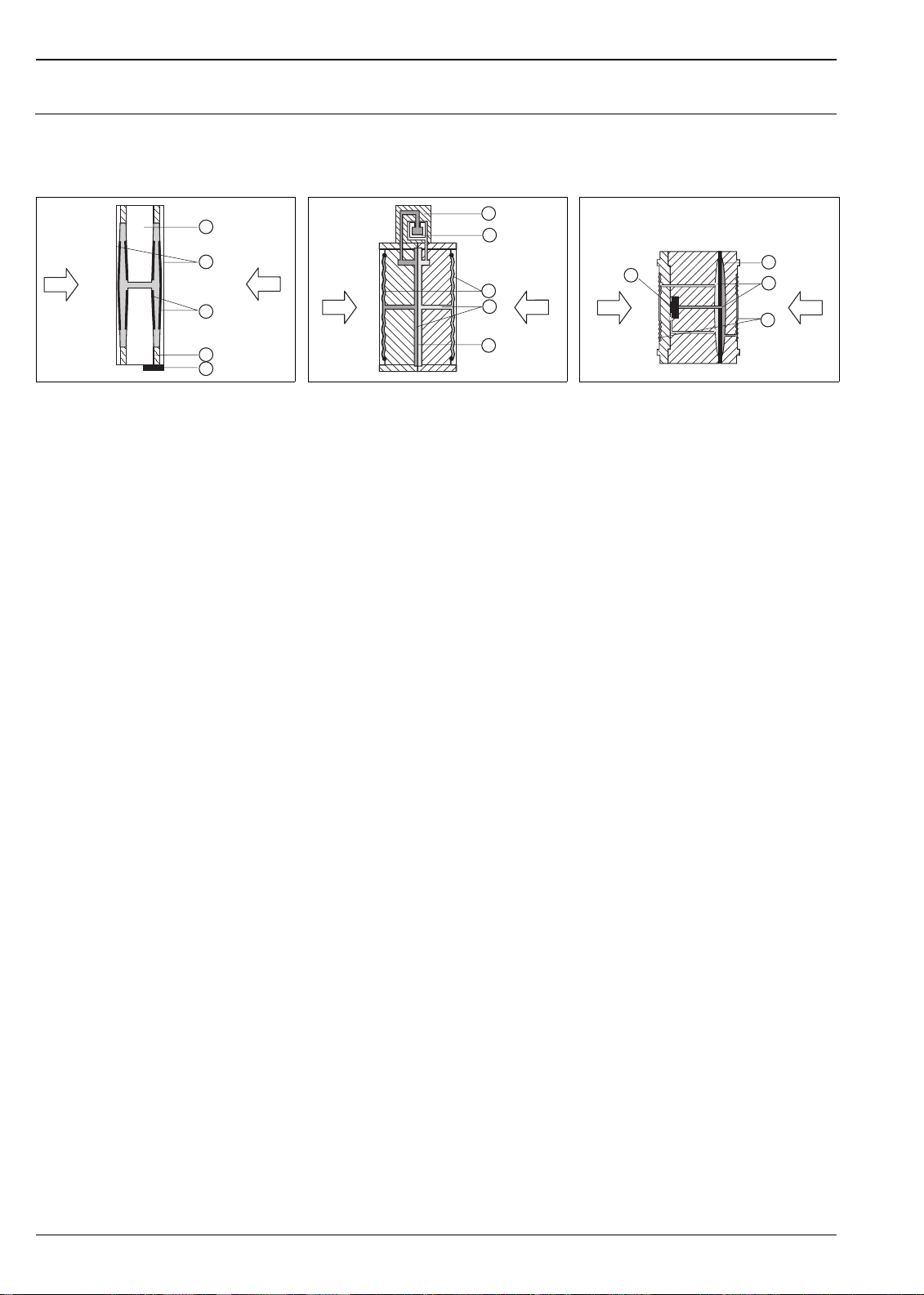
Measuring principle
Deltabar S
Ceramic measuring diaphragms used for PMD 70 and FMD 76
1
2
p
1
3
4
5
P01-xMD7xxxx-03-xx-xx-xx-000
Ceramic measuring cell PMD 70 and FMD 76
1 Meter body
2Diaphragm
3 Electrodes
4 Glass frit fixes the diaphragm onto the meter
body
5 Temperature sensor
p
2
Ceramic measuring diaphragms used for PMD 70 and FMD 76
The ceramic measuring cell is based on the principle of a plate capacitor with an electrode on (1) and a movable
electrode on the interior of the diaphragm (3). Standard silicone oil or mineral oil filling oils for this measuring
cell.
A differential pressure (p
are converted and are fed to the microprocessor of the transmitter as a digital signal.
Advantages:
• Self-monitoring for diaphragm break or oil loss (constant comparison of the measured temperature with a
temperature calculated from the capacitance values)
• Extremely high resistance to aggressive media
• Suitable for vacuums up to 0.02 psi
• Metal-free versions available
• Secondary process barrier for enhanced mechanical integrity
Metallic measuring diaphragms used for PMD 75, FMD 77 and FMD 78
1
2
6
5
P01-xMD7xxxx-03-xx-xx-xx-002
(1 mbar
abs
3
p
4
2
)
abs
p
1
Metal measuring cell for 40 inH2O (100 mbar) and
above
6 Sensing element
7 Overload diaphragm/Middle diaphragm
8 Filling oil
9 Separating diaphragm
p
1
Metal measuring cell 4 inH2O (10 mbar) and
12 inH
O (30 mbar)
2
1 Sensing element
2 Silicon diaphragm
3 Separating diaphragm
4 Filling oil
5 Integrated overload protection
≠ p2) causes a corresponding deflection of both diaphragms. Both capacitance values
1
7
8
p
2
9
P01-xMD7xxxx-03-xx -xx-xx-003
Metallic measuring diaphragms used for PMD 75, FMD 77 and FMD 78
The separating diaphragms (3/9) are deflected on both sides by the acting pressures. A filling oil (4/8) transfers
the pressure to a resistance circuit bridge (semi-conductor technology). The change due to differential pressure
of the bridge output voltage is measured and further processed.
Advantages:
• Standard operating pressures: 2320 psi and 6100 psi (160 bar and 420 bar)
• High long-term stability
• Very high single-sided overload resistance
• Secondary process barrier for enhanced mechanical integrity
6 Endress+Hauser
Page 7
Deltabar S
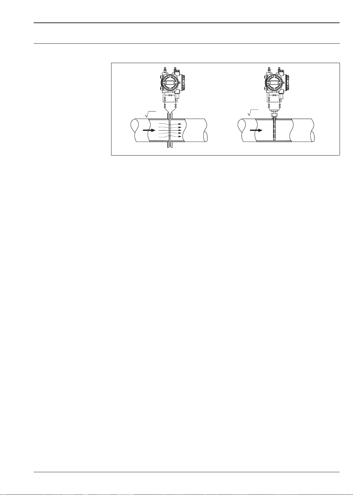
Flow measurement Design and operation mode
++
Dp
p
p
2
1
Dp
Q~
Q
Flow measurement with Deltabar S and primary element, left: Orifice plate and right: Pitot tube
QFlow
∆
p Differential pressure, ∆p = p1 – p
2
Q~
Q
––
p
p
1
2
P01-PMD7xxxx-15-xx-xx-xx-000
Your benefits
• Choice of four flow modes of operation: volume flow, norm volume flow (European norm conditions),
standard volume flow (American standard conditions) and mass flow.
• Choice of flow units with automatic unit conversion.
• User-specified custom measuring units.
• Low flow cut off: when activated, this function suppresses small flows which can lead to large fluctuations
in the measured value.
• Contains two totalizers as standard. One totalizer is user-resettable.
• The totalizing mode and unit can be individually set for each totalizer. This allows independent daily and
annual quantity totalizing.
Endress+Hauser 7
Page 8

Deltabar S
Level measurement (level, volume and mass)
Design and operation mode
–
–
h=
Dp
r g
1
h
2
+
3
+
P01xMD7xxxx-15-xx-xx-xx-000
Level measurement with Deltabar S
1 Level measurement via impulse piping and PMD 70
2 Level measurement with FMD 76
3 Level measurement via capillaries and FMD 78
h Height (level)
∆
p Differential pressure
ρ
Density of the medium
g Gravitation constant
Your benefits
• Choice of three level operating modes
• Volume and mass measurements in any tank shape by means of a freely programmable characteristic curve
• Choice of level units with automatic unit conversion
• User-specified custom measuring units
• Has a wide range of uses, e.g.
– for level measurement in tanks with static pressure
– in the event of foam formation
– in tanks with agitators of screen fittings
– in the event of liquid gases
– for standard level measurement
Communication protocol
• 4 to 20 mA with HART communication protocol
• PROFIBUS-PA
– The Endress+Hauser Deltabar S devices meet the requirements as per the FISCO model.
– Due to the low current consumption of 12 mA
– up to 9 Deltabar S for EEx ia, CSA IS and FM IS applications
– up to 32 Deltabar S for all other applications, e.g. in non-hazardous areas, EEx nA, etc.
can be operated at one bus segment with installation as per FISCO.
Further information on PROFIBUS-PA, such as requirements for bus system components, can be found in
the Operating Instructions BA 198F "PROFIBUS-DP/-PA: Guidelines for planning and commissioning" and
in the PNO guideline.
• Foundation Fieldbus
– The Endress+Hauser Deltabar S devices meet the requirements as per the FISCO model.
– Due to the low current consumption of 12 mA
– up to 9 Deltabar S for EEx ia, CSA IS and FM IS applications
– up to 32 Deltabar S for all other applications, e.g. in non-hazardous areas, EEx nA, etc.
can be operated on one bus segment with installation as per FISCO.
Further information on Foundation Fieldbus, such as requirements for bus system components, can be found
in the Operating Instructions BA 013S "Foundation Fieldbus Overview".
8 Endress+Hauser
Page 9
Deltabar S
Human interface
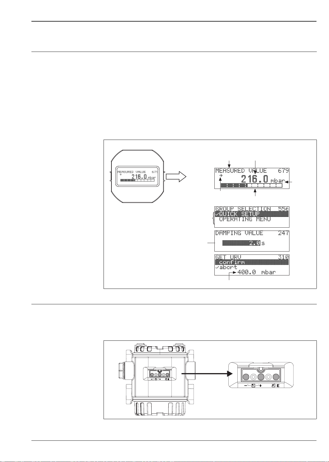
Display module (optional) A 4-line liquid crystal display (LCD) is used for display and operation. The display module shows measured
values, dialog text as well as fault and notice messages in plain text, thereby supporting the user in every stage
of operation.
Functions:
• 8-digit measured value display including sign and decimal point, bargraph for current display
• Simple and complete menu guidance due to separation of the parameters into three levels (blocks, groups
and functions)
• Each parameter is given a 3-digit ID number for easy navigation.
• Option for configuring the display according to individual requirements and desires, such as language,
alternating display, display of other measured values such as sensor temperature, contrast setting
• Comprehensive diagnostic functions (fault and warning message, peak-hold indicators, etc.)
• 4 to 20 mA HART: rapid and safe commissioning with the Quick Setup menus
Measured value display
Identification
number
Unit
Header line
Main line
Information
line
Function name Value
Symbol
Editing modes
Bargraph
Selection
option
Edit value
Current measured value
P01-xMD7xxxx-07-xx-xx-xx-000
Operating elements The operating buttons are located either under the protective cap on the exterior of the device or inside on the
electronic insert, depending on configuration of transmitter.
Operating buttons on the exterior of the device
P01-xxxxxxxx-19-xx-xx-xx-038
Endress+Hauser 9
Page 10
Deltabar S
The operating buttons located externally on the device work on the Hall sensor principle. This guarantees the
following advantages:
• Complete protection against environmental influences such as moisture and contamination
• Simple operation without any tools
• No wear
Note!
With the "External push buttons" option, a display module is always purchased. → See also page 53 ff, feature
20 "Electronics, communication, display, operation".
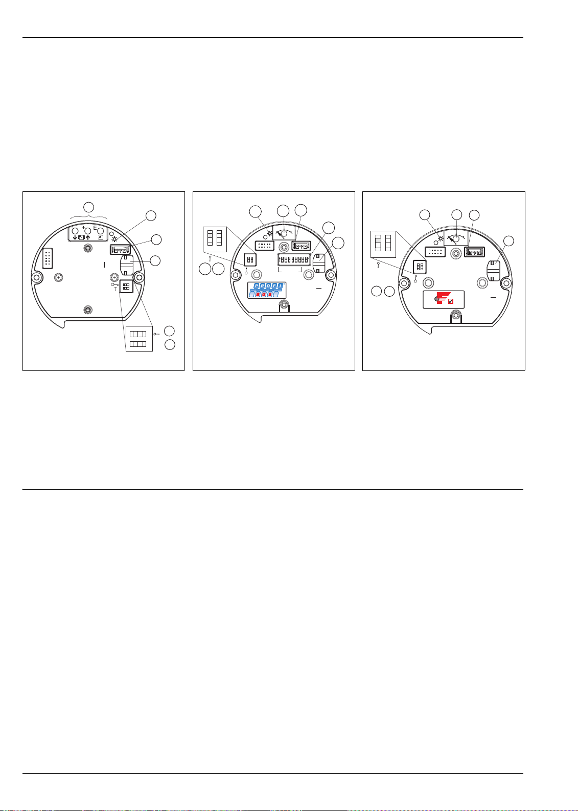
Operating keys and elements located internally on the electronic insert
1
2
3
4
PC
21
on
Sensor
Display
Histo
Damping
ROM
[]
off
5
t
6
onoff
P01-xxxxxxxx-19-xx-xx-xx-074
Electronic insert HART
1 Operating keys
2 Green LED to indicate acceptance of value
3 Slot for optional display
4 Slot for optional HistoROM
M-DAT
5 DIP-switch for locking/unlocking measured-
value parameters
6 DIP-switch for damping on/off
®
HistoROM
/M-DAT
(optional)
®
/
HistoROM®/M-DAT is a memory module, which is attached to the electronic insert. The HistoROM®/M-DAT
can be retrofitted into an existing transmitter.
2
0%
Zero
21
345 678
01
3
12
Address
3
Display
HW
CKON
SDA08
PC
5
678
SW
4
ROM
Histo
P01-xxxxxxxx-19-xx-xx-xx-075
4
5
1
off
on
2
1
7
6
on on
21
off off
Sensor
Electronic insert PROFIBUS PA
1 Green LED to indicate acceptance of value
2 Key for position calibration
3 Slot for optional display
4 Slot for optional HistoROM
®
/
M-DAT
5 DIP-switch for hardware address
6 DIP-switch without function
7 DIP-switch for locking/unlocking measured-
value parameters
Sensor
on
off
F
OUNDATION
2
0%
Zero
01
3
Display
P01-xxxxxxxx-19-xx-xx-xx-054
4
HW
PC
ROM
Histo
5
1
off
on
2
Simulation
6
1
21
Simulation
Electronic insert Foundation Fieldbus
1 Green LED to indicate acceptance of value
2 Key for position calibration
3 Slot for optional display
4 Slot for optional HistoROM
®
/
M-DAT
5 DIP-switch for simulation mode
6 DIP-switch for locking/unlocking measured-
value parameters
Your benefits
• Quick and safe commissioning of the same measuring points by copying the configuration data of one
transmitter to another transmitter
• Reliable process monitoring due to cyclical recording of pressure and sensor temperature measured values
• Simple diagnosis by recording events such as alarms, maximum indicators, counters for measuring
excursions outside user-specified pressure and temperature limits
• Analysis and graphic evaluation of the events and process parameters via ToF Tool (contained in scope of
supply)
®
HistoROM
/M-DAT can be ordered via feature 100 "Additional options 1" or feature 110 "Additional options
2". → See also page 53 ff.
10 Endress+Hauser
Page 11

Deltabar S
Local operation Functions 4 to 20 mA HART
• With display module: navigate through the operating menu using three operating buttons
• Without display module:
– Position calibration (zero point correction)
– Setting lower-range value and upper-range value – reference pressure present at device
– Value acceptance indicated by green LED
• Device reset
• Locking and unlocking measured-value parameters
• Switching damping on and off
Functions PROFIBUS-PA
• Position calibration (zero point correction)
• Value acceptance indicated by green LED
• Locking and unlocking measured-value parameters
• Setting hardware address
Functions Foundation Fieldbus
• Position calibration (zero point correction)
• Value acceptance indicated by green LED
• Locking and unlocking measured-value parameters
• Switching simulation mode on and off
Handheld terminals – HART With a handheld terminal, all the parameters can be configured anywhere along the 4 to 20 mA line via menu
operation.
ToF Tool – HART, PROFIBUS PA
The ToF Tool is a graphic and menu-guided operating program for measuring devices from
Endress+Hauser. It is used for supporting the commissioning, data storage, signal analysis and documentation
of the devices. The following operating systems are supported: Win95, Win98, WinNT4.0, Win2000 and
Windows XP. You can set all parameters via the ToF Tool.
The ToF Tool supports the following functions:
Configuration of transmitters in online operation
•
• Loading and saving device data (upload/download)
• HistoROM
®
/M-DAT analysis
• Documentation of the measuring point
Connection options:
• HART via Commubox FXA 191 and the serial interface RS 232 C of a computer
• PROFIBUS-PA via segment coupler and PROFIBUS interface card
• Service interface with adapter FXA 193
Commuwin II – HART, PROFIBUS-PA
Commuwin II is a graphically supported operating program for intelligent measuring devices with the
communication protocols HART and PROFIBUS-PA. The following operating systems are supported: Win 3.1/
3.11, Win 95, Win 98, WinNT4.0 and Win2000. Commuwin II displays the most important parameters.
Commuwin II supports the following functions:
• Configuration of measuring devices in online operation via matrix operation
• Loading and saving device data (upload/download)
• Visualization of measured and limit values
• Presentation and recording of measured values with a line recorder.
Connection option:
• HART via Commubox FXA 191 and the serial interface RS 232 C of a computer
• PROFIBUS PA via segment coupler and PROFIBUS interface card
Remote operation – Foundation Fieldbus
An FF configuration program is required to integrate a device with "Foundation Fieldbus signal" into an FF
network or to set the FF-specific parameters. Please contact your local Endress+Hauser Sales for more
information.
Endress+Hauser 11
Page 12

Deltabar S
Input
Measured variable Differential pressure, from which flow (volume or mass current) and level (level, volume or mass) are derived
Measuring range PMD 75, FMD 77, FMD 78 (with metallic measuring diaphragms)
7
7
2
sides
3480
(240)
3480
(240)
3480/9140
(240/630)
3480/9140
(240/630)
3480/9140
(240/630)
3480/9140
(240/630)
8
min.
operating
3
pressure
abs
0.001 (0.1) 7B –
7
0.001 (0.1) 7C –
7
0.001 (0.1) 7F 8F
0.001 (0.1) 7H 8H
0.001 (0.1) 7L 8L
0.001 (0.1) 7M 8M
Versions in the order
4
code
2320 psi
(PN 160)
6100 psi
6
(PN 420)
6
]
Nominal
Measurement limit Span MWP 1 Overload
value
lower (LRL) upper
(URL)
recommended
minimum
5
on one side on both
min./max.
psi [mbar] psi [mbar] psi [mbar] psi [mbar] psi [mbar] psi [bar] psi [bar] psi [bar] psi [mbar
4 inH
O
(10)
12 inH
(30)
40 inH
(100)
200 inH
(500)
O
2
O
2
O
2
(-10)
-12 inH2O
(-30)
-40 inH2O
(-100)
-200 inH2O
(-500)
-4 inH2O
2
43 (3000) -43
(-3000)
232
(16,000)
580
(40,000)
-232
(-16,000)
-580
(-40,000)
+4 inH2O
4 inH2O (10) 0.1 inH2O
(+10)
+12 inH2O
12 inH2O (30) 0.12 inH2O
(+30)
+40 inH2O
(+100)
+200 inH2O
(+500)
10/40 inH2O
(25/100)
13/200 inH2O
(33/500)
43 (+3000) 3/43
(200/3000)
+232
(+16,000)
+580
(+40,000)
15/232
1066/16,000
38/580
(2666/40,000)
(0.25)
(0.3)
2320
(160)
2320
(160)
2320
7
(160)
2320
7
(160)
0.4 inH2O (1) 2320 (160) 2320 (160) 3480 (240) 0.001 (0.1) 7D –
2 inH2O (5) 2320/6100
(160/420)
0.4 (30) 2320/6100
(160/420)
2 (160) 2320/6100
(160/420)
6 (400) 2320/6100
(160/420)
2320/6100
(160/420)
2320/6100
(160/420)
2320/6100
(160/420)
"+"side:
2320/6100
(160/420)
1) MWP = Maximum working pressure. → See also page 26, section "Pressure specifications".
2) FMD 77, FMD 78: The maximum pressure for the measuring device is dependent on the lowest-rated element, with regard to pressure, of the
selected components. → See also page 26, section "Pressure specifications".
3) The specified minimum operating pressure applies to the PMD 75 at the reference operating conditions for silicone oil. Min. operating
pressure at 185°F (85°C) for silicone oil: 0.145 psi
must also be observed for the FMD 77 and FMD 78. → See also page 46, section "Diaphragm seal filling oils".
(10 mbar
abs
). The pressure and temperature application limits of the selected filling oil
abs
4) Versions in the order code → See also page 53 ff, feature 40 "Measuring cell, nominal operating range, PN"
5) Minimum span that can be calibrated, turn down > 100:1 on request
6) 2320 psi (PN 160) versions with stainless steel M12 bolts, 6100 psi (PN 420) versions with steel M12 bolts, surface coating GEOMET
7) With copper seal: "MWP": max. 1450 psi (100 bar); "Overload on one side" and "Overload on both sides": max. 2175 psi (150 bar)
8) "–"side: 1450 psi (100 bar)
12 Endress+Hauser
Page 13
Deltabar S
PMD 70, FMD 76 (with ceramic measuring diaphragms)
Nominal
Measurement limit Span MWP
1
Overload
value
lower (LRL) upper (URL) recom-
minimum
5
on one side on both
mended
min./max.
inH
O
2
[mbar]
inH2O [mbar] inH2O
[mbar]
inH2O [mbar] inH2O [mbar] psi [bar] psi [bar] psi [bar] psi [mbar
10 (25) -10 (25) +10 (+25) 10 (25) 0.1 (0.25) 145 (10) 145 (10) 217 (15) 14 (1) 7B
40 (100) -40 (-100) +40 (+100) 10/40 (25/100) 0.4 (1) 232 (16) 232 (16) 348 (24) 14 (1) 7D
200 (500) -200 (-500) +200 (+500) 13/200 (33/500) 2 (5) 1450 (100) 1450 (100) 2175 (150) 14 (1) 7F
1200 (3000) -1200 (-3000) +1200
(+3000)
80/1200
(200/3000)
12 (30) 1450 (100) 1450 (100) 2175 (150) 14 (1) 7H
1) MWP = Maximum working pressure. → See also page 26, section "Pressure specifications".
2) The specified overload only applies to the measuring cell. The maximum pressure for the measuring device is dependent on the weakest element,
with regard to pressure, of the selected components. → See also page 26, section "Pressure specifications".
3) Min. operating pressure at the reference operating conditions for silicone oil. Min. operating pressure at 185°F (85°C): to 0.145 psi
4) Versions in the order code → See also page 53 ff, feature 40 "Measuring cell, nominal operating range, PN"
5) Minimum span that can be calibrated, turn down > 100:1 on request
2
Min.
operating
pressure
3
Versions in the
order code
4
sides
]
abs
(10 mbar abs)
abs
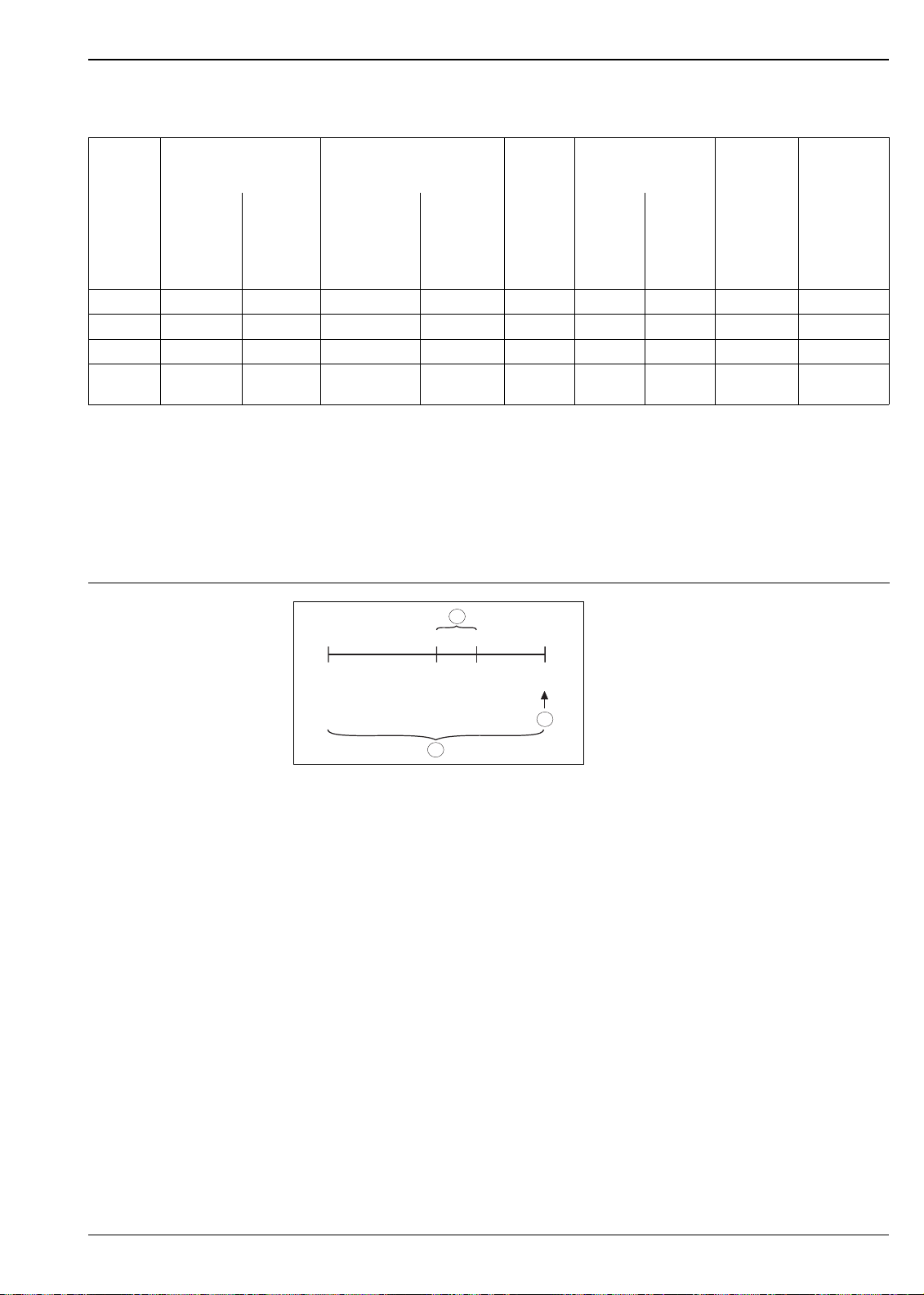
Explanation of terms
1
LRV
0
(40 inH O)
3
URV
100
LRL
–500 mbar
(-200 inH O)
2
Example: 200 inH2O (500 mbar) sensor
1Set span
2Nominal value
i
Upper range limit (URL)
3 Nominal measuring range
LRL Lower range limit
URL Upper range limit
LRV Lower range value
URV Upper range value
URL
+ 500 mbar
(+200 inH O)
2
2
P01-xxxxxxxx-05-xx-xx-xx-001
2
Explanation of the term 'Turn down (TD)'
(TD = turn down)
Turn down = nominal value/set span
Example:
Nominal value = 200 inH
Set span = 40 inH
TD = 5:1
O (500 mbar)
2
O (100 mbar)
2
Endress+Hauser 13
Page 14
Output
Output signal • 4 to 20 mA with superimposed digital communication protocol HART, 2-wire
• Digital communication signal PROFIBUS-PA (Profile 3.0)
• Digital communication signal Foundation Fieldbus
Deltabar S
Signal on alarm
Load – 4 to 20 mA HART
• 4 to 20 mA HART
Options:
– Max. alarm*: can be set from 21 to 23 mA
– Keep measured value: last measured value is kept
– Min. alarm: 3.6 mA
* Factory setting: 22 mA
• PROFIBUS-PA: can be set in the Analog Input block, options: good, bad, uncertain
• Foundation Fieldbus: can be set, options: good, bad, uncertain
R
1
L
max
[]W
1500
1282
847
4
413
10.5
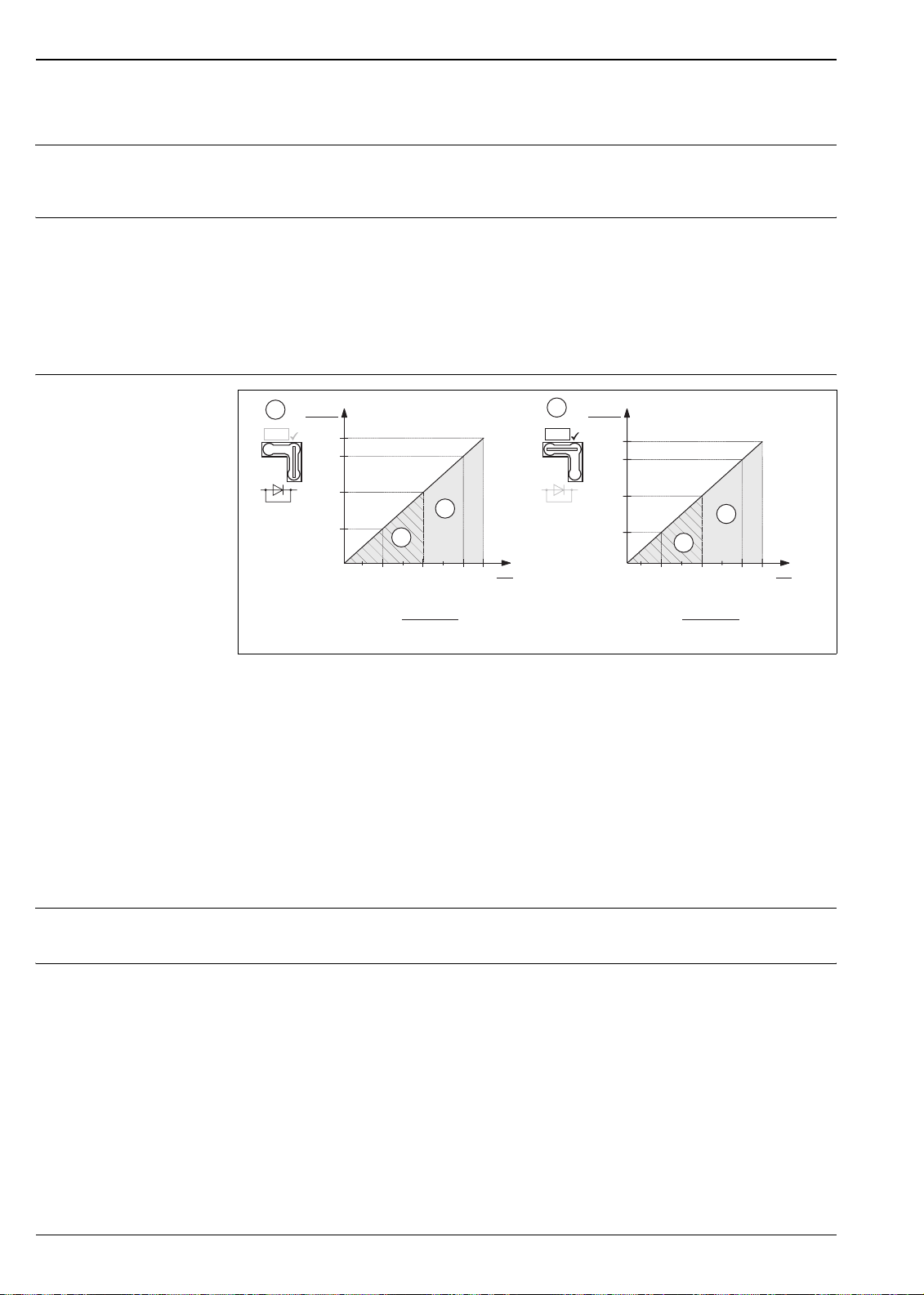
Load diagram, observe the position of the jumper and the explosion protection (→ See also page 16, section "Measuring 4
to 20 mA test signal".)
1 Jumper for 4 to 20 mA test signal inserted in "Standard" position
2 Jumper for 4 to 20 mA test signal inserted in "Test" position
3 Supply voltage 10.5 (11.5) to 30 V DC for EEx ia, 1/2 D, 1 GD, 1/2 GD, FM IS and CSA IS
4 Supply voltage 10.5 (11.5) to 45 V DC for device for non-hazardous areas, 1/3 D, EEx d, EEx nA, FM XP, FM DIP,
FM NI, CSA XP and CSA Dust-Ex
Maximum load resistance
R
Lmax
U Supply voltage
3
40 45
[V]
U
30
20
U – 10.5 V
R
£
L
max
23 mA
R
2
L
max
TestTest
[]W
1456
1239
804
4
369
11.5
3
30
20
U – 11.5 V
R
£
L
max
23 mA
U
40 45
[V]
P01-xMD7xxxx-05-xx-xx-xx-000
Note!
When operating via a handheld terminal or via PC with an operating program, a minimum communication
resistance of 250 Ω must exist within the loop.
Resolution
• Current output: 1 µA
• Display: can be set (setting at the factory: presentation of the maximum accuracy of the transmitter)
Reading cycle
• HART commands: on average 3 to 4 per second
• PROFIBUS-PA:
– cyclic: on average 100/s
– acyclic: on average 20/s
• Foundation Fieldbus:
– cyclic up to 5/s, dependent on the number and type of function blocks used in a closed-control loop
– acyclic: 10/s
14 Endress+Hauser
Page 15
Deltabar S
Damping • Via display module, handheld terminal or PC with operating program, continuous from 0...999 s
• Additionally for HART: via DIP-switch on the electronic insert, switch position "On = set value" and "Off"
• Factory setting: 2 s
Power supply
Electrical connection Note!
• When using the measuring device in hazardous areas, installation must comply with the corresponding
national standards and regulations and the Safety Instructions (XAs) or Installation or Control Drawings
(ZDs). → See also page 67, section "Safety Instructions" and "Installation/Control Drawings".
• Protective circuits against reverse polarity, HF influences and overvoltage peaks are installed.
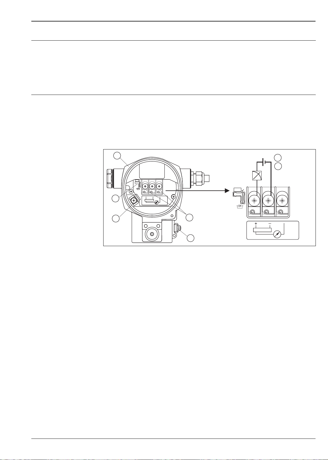
4 to 20 mA HART
1
Test
2
3
4... 20mA
Test
5
4to20mA
Test
4 to 20mA
4
Electrical connection 4 to 20 mA HART
1Housing
2 Jumper for 4 to 20 mA test signal.
→ See also page 16, section "Measuring 4 to 20 mA" .
3 Internal ground terminal
4 External ground terminal
5 4 to 20 mA test signal between positive and test terminal
6 Minimum supply voltage = 10.5 V DC, jumper is inserted in accordance with the illustration.
7 Minimum supply voltage = 11.5 V DC, jumper is inserted in "Test" position.
PROFIBUS PA
The two-wire cable must be connected to the "PA+" and "PA–" terminals.
10.5 V DC
6
11.5 V DC
7
Test
P01-xMx7xxxx-04-xx-xx-xx-001
Foundation Fieldbus
The two-wire cable must be connected to the "FF+" and "FF–" terminals.
Endress+Hauser 15
Page 16
Deltabar S
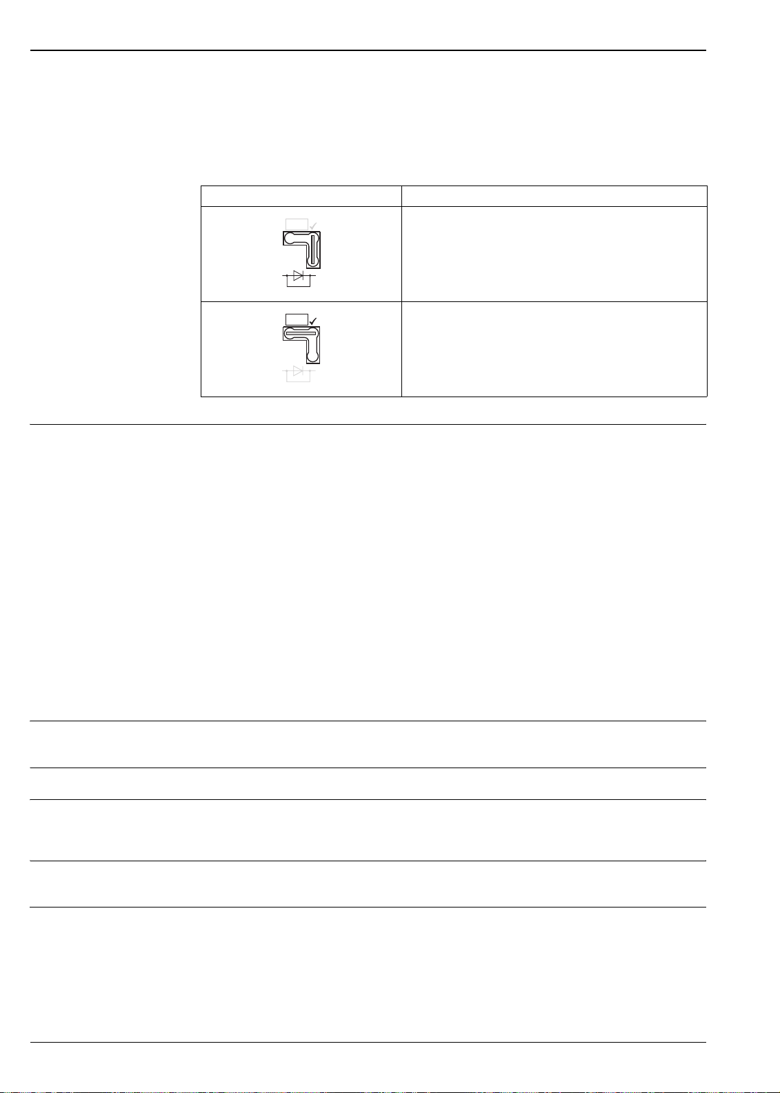
Measuring 4 to 20 mA test signal
A 4 to 20 mA signal may be measured via the positive and test terminal without interrupting the measurement.
The minimum supply voltage of the device can be reduced by simply changing the position of the jumper. As
a result, operation is also possible with lower voltage sources. Observe the position of the jumper in accordance
with the following table.
Jumper position for test signal Description
Test
– Measuring 4 to 20 mA test signal via plus and test terminal:
not possible.
– Delivery status
– minimum supply voltage: 10.5 V DC
Supply voltage Note!
• When using the measuring device in hazardous areas, installation must comply with the corresponding
national standards and regulations and the Safety Instructions (XAs) or Installation or Control Drawings
(ZDs).
• All explosion protection data are given in separate documentation which is available upon request. The Ex
documentation is supplied as standard with all devices approved for use in explosion hazardous areas. → See
also page 67, sections "Safety Instructions" and "Installation/Control drawing".
4 to 20 mA HART
• Version for non-hazardous areas, jumper for 4 to 20 mA test signal in "Standard" position: 10.5 to 45 V DC
• Version for non-hazardous areas, jumper for 4 to 20 mA test signal in "Test" position:
11.5 to 45 V DC
PROFIBUS-PA
Version for non-hazardous areas: 9 to 32 V DC
Foundation Fieldbus
Version for non-hazardous areas: 9 to 32 V DC
Test
– Measuring 4 to 20 mA test signal via plus and test terminal:
possible. (Thus, the output current can be measured without
interruption via the diode.)
– minimum supply voltage: 11.5 V DC
Current consumption
• PROFIBUS-PA: 11 mA ± 1 mA, switch-on current corresponds to table 4, IEC 61158-2
• Foundation Fieldbus: 11 mA ± 1 mA, switch-on current corresponds to table 4, IEC 61158-2
Cable entry → See also page 53 ff , feature 30 "Housing, Cable entry, Protection".
Cable specification
• Endress+Hauser recommends using shielded, twisted-pair two-wire cables.
• Terminals for wire cross-sections 0.5 to 2.5 mm
2
• Cable external diameter: 5 to 10 mm
Residual ripple Without influence on 4 to 20 mA signal up to ± 5 % residual ripple within the permitted voltage range
[according to HART hardware specification HCF_SPEC-54 (DIN IEC 60381-1)]
Influence of power supply ≤ 0.0006% of URL/1 V
16 Endress+Hauser
Page 17

Deltabar S
Performance characteristics – general
Reference operating conditions • As per IEC 60770
• Ambient temperature T
• Humidity ϕ = constant, in the range of: 45 to 75 % r.H
• Ambient pressure p
• Position of the measuring cell: constant, in the range of: ±1°
• Input of LOW SENSOR TRIM and HIGH SENSOR TRIM for lower range value and upper range value
• Zero based span
• Membrane material PMD 75, FMD 77, FMD 78: AISI 316L
• Membrane material PMD 70, FMD 76: Al
• Filling oil: silicone oil
= constant, in the range of: +69.8 to +91.4°F (+21 to +33°C)
U
= constant, in the range of: 12 to 15 psi (860 to 1060 mbar)
U
(Aluminum oxide ceramic)
2O3
Long-term stability Measuring cells ≥ 200 inH
O (500 mbar):
2
• ±0.05% of URL/year
• ±0.125% of URL/5 years
Measuring cells ≤ 40 inH
O (100 mbar):
2
• ±0.18% of URL/year
Influence of the installation position
Vibration effects PMD 70, PMD 75: ≤ Reference accuracy to 15 to 25 Hz: 1.6 mm; 25 to 1000 Hz: 4g
Position-dependent zero shift can be corrected. → See also page 21, section "General installation instructions"
and page 50 ff, section "Installation instructions, Diaphragm seal systems".
Performance characteristics – metallic diaphragms
Reference accuracy – PMD 75, FMD 77, FMD 78
The reference accuracy comprises the non-linearity including hysteresis and non-reproducibility in accordance
with the limit point method as per IEC 60770.
PMD 75
O (10 mbar), 12 inH2O (30 mbar) measuring cells:
4 inH
2
• TD 1:1: ±0.15% of URV
• TD > 1:1: ±0.15% of URV x TD
O (100 mbar) measuring cell:
40 in H
2
• TD 1:1 to TD 4:1: ±0.075% [±0.05%] of URV
• TD > 4:1: ±(0.012 • TD + 0.027)% of URV
Measuring cells ≥ 200 inH
O (500 mbar):
2
• TD 1:1 to TD 15:1: ±0.075% [±0.05%] of URV
• TD > 15:1: ±(0.0015 • TD + 0.05252)% of URV
FMD 77, FMD 78
O (100 mbar) measuring cell:
40 in H
2
• TD 1:1 to TD 4:1: ±0.075% of URV + influence from the diaphragm seal
• TD > 4:1: ±(0.012 • TD + 0.027)% of URV + influence from the diaphragm seal
Measuring cells ≥ 200 inH
O (500 mbar):
2
• TD 1:1 bis TD 15:1: ±0.075% of URV + influence from the diaphragm seal
• TD > 15:1: ±(0.0015 • TD + 0.05252)% of URV + influence from the diaphragm seal
– Values in brackets [ ] for devices with improved reference accuracy (PLATINUM version)
– The following applies for the root-extracting characteristic curve:
The accuracy data of the Deltabar S is taken into the accuracy calculation of the flow rate with a factor of 0.5.
Endress+Hauser 17
Page 18

Deltabar S
Total performance – PMD 75
Warm-up period – PMD 75, FMD 77, FMD 78
Dynamic response time (T63) – PMD 75, FMD 77, FMD 78
The "Total performance" specification comprises the non-linearity including hysteresis, non-reproducibility, the
thermal change of the zero point as well as the influence of the line pressure (p
• ±0.15% of URV
1. For measuring ranges ≥ 200 inH2O (500 mbar) to TD 2:1
2. All specifications apply to the temperature range +14 to +140°F (–10 to +60°C).
1, 2
= 1015 psi / 70 bar).
st
5.4 s
I
100 %
63 %
t1t
2
Dynamic response time
Type Dead time t
PMD 75 45 ms • 12 inH2O (30 mbar) measuring cell: 200 ms
1
Time constant (T63), t
• 40 inH
• 200 inH
• 43 psi (3 bar) measuring cell: 40 ms
FMD 77, FMD 78 dependent on the diaphragm seal
t
O (100 mbar) measuring cell: 60 ms
2
O (500 mbar) measuring cell: 45 ms
2
P01-xxxxxxxx-05-xx-xx-xx-007
2
Influence of the operating pressure on zero point and span – PMD 75, FMD 77, FMD 78
Measuring cell 4 inH2O (10 mbar) 12 inH2O (30 mbar) 40 inH2O (100 mbar) 200 inH2O (500 mbar)
Influence of the
operating pressure
on the zero point
Influence of the
operating pressure
on the span
Measuring cell 45 psi (3 bar) 230 psi (16 bar) 600 psi (40 bar)
Influence of the
operating pressure on
the zero point
Influence of the
operating pressure on
the span
±0.15% of URL/
100 psi (7 bar)
±0.035% of URL/
100 psi (7 bar)
±0.075% of URL/
1015 psi (70 bar)
±0.14% of URL/
1015 psi (70 bar)
±0.35% of URL/
1015 psi (70 bar)
±0.14% of URL/
1015 psi (70 bar)
±0.075% of URL/
1015 psi (70 bar)
±0.14% of URL/
1015 psi (70 bar)
±0.15% of URL/
1015 psi (70 bar)
±0.14% of URL/
1015 psi (70 bar)
±0.075% of URL/
1015 psi (70 bar)
±0.14% of URL/
1015 psi (70 bar)
±0.075% of URL/
1015 psi (70 bar)
±0.14% of URL/
1015 psi (70 bar)
Note!
The influence of the operating pressure on the zero point can be calibrated out.
18 Endress+Hauser
Page 19

Deltabar S
Thermal change of the zero
output and the output span –
PMD 75
Reference accuracy – PMD 70, FMD 76
+14 to +140°F (–10 to +60°C):
• 4, 12 inH
• 40 inH
• 200 inH
O (10 mbar, 30 mbar) measuring cell: ±(0.31 • TD + 0.06)% of URV
2
O (100 mbar) measuring cell: ±(0.18 • TD + 0.02)% of URV
2
O, 45 psi (500 mbar, 3 bar) measuring cell: ±(0.08 • TD + 0.05)% of URV
2
• 230 psi (16 bar) measuring cell: ±(0.1 • TD + 0.1)% of URV
• 600 psi (40 bar) measuring cell: ±(0.025 • TD + 0.05)% of URV
–40 to +14°F, +140 to +185°F (–40 to –10°C, +60 to +85°C):
• 4, 12 inH
• 40 inH
• 200 inH
O (10 mbar, 30 mbar) measuring cell: ±(0.45 • TD + 0.1)% of URV
2
O (100 mbar) measuring cell: ±(0.3 • TD + 0.15)% of URV
2
O, 45 psi (500 mbar, 3 bar) measuring cell: ±(0.12 • TD + 0.1)% of URV
2
• 230 psi (16 bar) measuring cell: ±(0.15 • TD + 0.2)% of URV
• 600 psi (40 bar) measuring cell: ±(0.37 • TD + 0.1)% of URV
Performance characteristics – ceramic diaphragms
The reference accuracy comprises the non-linearity including hysteresis and non-reproducibility in accordance
with the limit point method as per IEC 60770.
10 inH
O (25 mbar) measuring cell:
2
• TD 1:1: ±0.15% of URV
• TD > 1:1: ±0.15% of URV x TD
O (100 mbar) measuring cell:
40 inH
2
• TD 1:1 to TD 4:1: ±0.075% [±0.05%] of URV
• TD > 4:1: ±(0.012 • TD + 0.027)% of URV
200 inH
• TD 1:1 to TD 15:1: ±0.075% [±0.05%] of URV
• TD > 15:1: ±(0.0015 • TD + 0.05252)% of URV
O, 43 psi (500 mbar, 3 bar) measuring cell:
2
Total performance – PMD 70, FMD 76
Warm-up period – PMD 70, FMD 76
– Values in brackets [ ] for devices with improved reference accuracy (PLATINUM version)
– The following applies for the root-extracting characteristic curve:
The accuracy data of the Deltabar S is taken into the accuracy calculation of the flow rate with a factor of 0.5.
The "Total performance" specification comprises the non-linearity including hysteresis, non-reproducibility, the
thermal change of the zero point as well as the influence of the line pressure (p
• ±0.15% of URV
1. For measuring ranges ≥ 200 inH
2. All specifications apply to the temperature range +14 to +140°F (–10 to +60°C).
1, 2
O (500 mbar), TD 1:1
2
= 1015 psi / 70 bar).
st
5.4 s
Endress+Hauser 19
Page 20

Deltabar S
Dynamic response time (T63) – PMD 70, FMD 76
Influence of the operating pressure on zero point and span – PMD 70, FMD 76
I
100 %
63 %
t1t
2
Dynamic response time
Type Dead time t
PMD 70, FMD 76 90 ms • 10 inH2O (25 mbar) measuring cell: 4700 ms
Measuring cell 10 inH2O (25 mbar) 40 inH2O (100 mbar) 200 inH2O (500 mbar) 45 psi (3 bar)
Influence of the
operating pressure
on the zero point
Influence of the
operating pressure
on the span
±0.7% of URL/
100 psi (7 bar)
±0.14% of URL/
1015 psi (70 bar)
1
±0.175% of URL/
100 psi (7 bar)
±0.14% of URL/
1015 psi (70 bar)
Time constant (T63), t
• 40 inH
•
O (100 mbar) measuring cell: 280 ms
2
200 inH2O (500 mbar) measuring cell: 210 ms
±0.075% of URL/
1015 psi (70 bar)
±0.14% of URL/
1015 psi (70 bar)
t
P01-xxxxxxxx-05-xx-xx-xx-007
2
±0.075% of URL/
1015 psi (70 bar)
±0.14% of URL/
1015 psi (70 bar)
Thermal change of the zero
output and the output span –
PMD 70, FMD 76
Note!
The influence of the operating pressure on the zero point can be calibrated out.
+14 to +140°F (–10 to +60°C):
• 10 inH
• ≥ 40 inH
O (25 mbar) measuring cell: ±(0.35 • TD + 0.05)% of URV
2
O (100 mbar) measuring cells: ±(0.05 • TD + 0.05)% of URV
2
–40 to +14°F, +140 to +185°F (–40 to –10°C, +60 to +85°C):
• 10 inH
• ≥ 40 inH
O (25 mbar) measuring cell: ±(0.3 • TD + 0.15)% of URV
2
O (100 mbar) measuring cells: ±(0.08 • TD + 0.07)% of URV
2
20 Endress+Hauser
Page 21

Deltabar S
Operating conditions (installation)
General installation instructions • For FMD 77 and FMD 78: See page 50 ff, "Installation instructions, Diaphragm seal systems" section.
• The position-dependent zero shift can be corrected directly at the device via operating keys, even in
hazardous areas. Diaphragm seals also shift the zero point, depending on the installation position (→ See also
page 50 ff, "Installation instructions, Diaphragm seal systems").
• The housing of the Deltabar S can be rotated up to 380°. → See also page 22, section "Rotating the
housing".
• Endress+Hauser offers a mounting bracket for installing on pipes or walls. → See also page 22, section
"Wall- and pipe-mounting".
• When measuring in media with solid proportions, such as dirty liquids, installing separators and drain valves
is useful for capturing and removing sediment.
• Using a three-valve or five-valve manifold allows for easy commissioning, installation and maintenance
without interrupting the process.
• General recommendations for the impulse piping can be found in DIN 19210 "Methods for measurement of
fluid flow; differential piping for flow measurement devices" or the corresponding national or international
standards.
• Install the impulse piping with a continuous gradient of at least 10%.
• When routing the impulse piping outdoors, ensure that sufficient anti-freeze protection is used, e.g. by using
pipe heat tracing.
Measuring arrangement Flow measurement
• The PMD 70 and PMD 75 are best suited to flow measurement.
• Measuring arrangement for gases: Mount device above the measuring point.
• Measuring arrangement for liquids and steam: Mount device below tapping point.
• For flow measurement in steam, mount the condensate traps at the same level as the tapping point and at
the same distance from Deltabar S.
Level measurement
• PMD 70, PMD 75, FMD 76 and FMD 77 are best suited to level measurement in open tanks. All Deltabar
S devices are suitable for level measurement in closed tanks.
Measuring arrangement level measurement in open tanks
• PMD 70, PMD 75: Mount device below the lower measuring connection. The negative side is open to
atmosphere pressure.
• FMD 76, FMD 77: Mount device directly on the tank or with shut-off valve. The negative side is open to
atmospheric pressure.
Measuring arrangement level measurement in closed tanks and closed tanks with static pressure
• PMD 70, PMD 75: Mount device below the lower measuring connection. Always connect the negative side
above the maximum level.
• FMD 76, FMD 77: Mount device directy on the tank. Always connect the negative side above the maximum
level.
• In the case of level measurement in closed tanks with static pressure, a condensate trap ensures pressure
which remains constant on the minus side.
Pressure measurement
• The PMD 70 and PMD 75 are best suited to differential pressure measurement.
• Measuring arrangement for gases: Mount device above the measuring point.
• Measuring arrangement for liquids and steam: Mount device below tapping point.
• For differential pressure measurement in steam, mount the condensate traps at the same level as the tapping
point and at the same distance from Deltabar S.
Endress+Hauser 21
Page 22

Deltabar S
Wall- and pipe-mounting Endress+Hauser offers a mounting bracket for installing on pipes or walls. → See also page 53 ff, feature 110,
"Additional options 2".
Note!
If a manifold valve is used, its dimensions should also be taken into consideration.
~ 12.2”
310)
6.62”
(66.5)
3.41”
(86.5)
(
4.25”
(108)
4.84”
(123)
0.39”
(10)
max. ø2.50”
(63)
2.91”
(74)
5.63”
(143)
1.77”
(45)
~ 8.66”
(220)
~ 11.4”
(290)
Rotating the housing The housing can be rotated up to 380° by loosening the Allen screw.
Your benefits
• Simple mounting by optimally aligning the housing
• Good, accessible device operation
• Optimum readability of the display module (optional).
max. 380°
3.94”
(100)
P01-xMD7xxxx-17-xx-xx-xx-000
P01-xMD7xxxx-17-xx-xx-xx-001
Align the housing by loosening the Allen screw with an Allen key (2 mm)
22 Endress+Hauser
Page 23

Deltabar S
Oxygen applications Oxygen and other gases can react explosively to oils, grease and plastics, such that, among other things, the
following precautions must be taken:
– All components of the system, such as measuring devices, must be cleaned in accordance with standard
requirements (BAM, DIN 19247, CGA-4.1-1996, AGA G93-96).
– Dependent on the materials used, maximum temperature and a maximum pressure must not be exceeded.
The devices suitable for oxygen applications are listed in the following table with the specifications T
.
p
max
max
and
Order code for devices cleaned for
oxygen applications
PMD 70 – _ _ _ _ _ _ _ _ 2 _ _ 600 psi (40 bar) 140°F (60°C) FKM Viton V80G2 seal
PMD 75 – _ _ _ _ _ _ _ _ K _ _ 230 psi (160 bar)
PMD 75 – _ _ _ _ _ _ _ _ 2 _ _ 600 psi (40 bar)
PMD 75 – _ _ _ _ _ _ _ _ 3 _ _ 435 psi (30 bar)
FMD 76 – _ _ _ _ _ _ T _ _ _ 600 psi (40 bar) 140°F (60°C) FKM Viton V80G2 seal
FMD 77 – _ _ _ _ _ T _ F _ _ 600 psi (40 bar) 140°F (60°C) FKM Viton V80G2 seal
FMD 78 – _ _ _ _ _ _ __ 4 _ _ 1300 psi (90 bar) 140°F (60°C) Fluorolube FS-5 filling oil
1) For devices with 4 inH2O (10 mbar) and 12 inH2O (30 mbar) measuring cell: 1450 psi (100 bar)
2) Higher pressures on request
p
for oxygen
max
applications
T
for oxygen
max
applications
1
140°F (60°C) Halocarbon 6.3
2
140°F (60°C) FKM Viton V80G2 seal
2
140°F (60°C) PTFE seal GF 25
Restrictive component
(copper ring seal)
Ultra pure gas applications Endress+Hauser also offers degreased devices for special applications, such as ultra pure gas.
No special restrictions regarding the process conditions apply to these devices.
→ See also page 53 ff, PMD 70 and PMD 75: feature 80 "Gasket material", FMD 76 and FMD 77: feature 70
"Process connection low-pressure side, material, seal".
Diaphragms for materials with
hydrogen build-up (RhodiumGold coating)
When materials are used in which hydrogen build-up occurs, hydrogen atoms can diffuse through the metals
of the sensor. This can lead to corrupt measurement results.
Endress+Hauser offers diaphragms with Rhodium-Gold coating for this application.
→ See also page 56 "Ordering information PMD 75", page 62 "Ordering information FMD 77" or page 65
"Ordering information FMD 78", feature 60 "Material diaphragm".
Operating conditions (Environment)
Ambient temperature range • PMD 75, FMD 77, FMD 78: –40 to +185°F (–40 to +85°C),
devices for lower temperatures on request
• PMD 70, FMD 76: –40 to +185°F (–40 to +85°C)
For devices for use in hazardous areas, see Safety instructions (XA...), Installation or Control Drawing (ZD...).
(→ See also page 67, sections "Safety Instructions" and "Installation/Control drawings".)
The device can be used in this temperature range; however, certain specification values, such as accuracy, can
be exceeded. → See also DIN 16086.
Endress+Hauser 23
Page 24

Deltabar S
Storage temperature range • –40 to +212°F (–40 to +100°C)
• Display module: –40 to +185°F (–40 to +85°C)
Degree of protection → See page 53 ff, feature 30 "Housing, Cable entry, Protection".
Climate class Class 4K4H (air temperature:–4 to +131°F/ –20 to 55°C , relative humidity: 4 to 100%) fulfilled as per
DIN EN 60721-3-4 (condensation possible)
Vibration resistance PMD 70, PMD 75: guaranteed for 15 to 25 Hz: 1.6 mm; 25 to 1000 Hz: 4 g in all 3 planes
Electromagnetic compatibility
Overvoltage protection Protective diodes: gas discharger 230 V, nominal discharge current 10 kA
Interference emission as per EN 61326 electrical device B, Interference immunity as per EN 61326 appendix
A (industrial use) and NAMUR EMC recommendation (NE 21).
With increased interference immunity against electromagnetic fields as per EN 61000-4-3: 30 V/m
→ See also page 53 ff, feature 100 "Additional options 1" and feature 110 "Additional options 2".
Operating conditions (Process)
Process temperature limits • PMD 70: –40 to +185°F (–40 to +85°C)
• FMD 76: –40 to +185°F (–40 to +85°C)
• PMD 75: –40 to +248°F (–40 to +120°C),
with side flanges C22.8: 14 to +248°F (–10 to +120°C)
• FMD 77 and FMD 78, depending on the diaphragm seal and filling oil: up to +662°F (+ 350°C)
Note!
• For oxygen applications, observe page 23 "Oxygen applications" section.
• PMD 70, FMD 76, PMD 75 and FMD 78: Observe the temperature operating range of the seal.
→ See also the following section "Temperature operating range, seals".
• FMD 77 and FMD 78: Observe the temperature application limits of the diaphragm seal oil.
→ See also page 46, sections "Diaphragm seal filling oils".
• FMD 77 and FMD 78: Do not use diaphragm seals with 0.09 mm PTFE foil on AISI 316L (1.4435/1.4405)
for vacuum applications; upper temperature limit +400°F (+205°C).
Temperature operating range, seals
PMD 70 (with ceramic measuring diaphragms)
Versions in the order code Seal Temperature operating range
A FKM Viton, Compound VC601 –4 to +185°F (–20 to +85°C)
B EPDM, Compound E 7502 –4 to +185°F (–20 to +85°C)
C Kalrez, Compound 6375 +41 to +185°F (+5 to +85°C)
1 FKM Viton, degreased,
Compound V 80G2
2 FKM Viton, cleaned for oxygen service,
Compound V80G2
1) Seal for lower temperatures on request
+14 to +185°F (–10 to +85°C)
+14 to +140°F (–10 to +60°C)
1
24 Endress+Hauser
Page 25

Deltabar S
FMD 76 (with ceramic measuring diaphragms)
Versions in the order code Seal Temperature operating range
B, D, F, G, U FKM Viton, Compound VC601 –4 to +185°F (–20 to +85°C)
K, L EPDM, Compound E7502,
–4 to +185°F (–20 to +85°C)
FDA 21 CFR 177.2600
M, N Kalrez, Compound 6375 +41 to +185°F (+5 to +85°C)
P, Q Chemraz, Compound 505 –4 to +185°F (–20 to +85°C)
S FKM Viton, degreased,
+14 to +185°F (–10 to +85°C)
Compound V80G2
T FKM Viton, cleaned for oxygen service,
+14 to +140°F (–10 to +60°C)
Compound V80G2
1) Seal for lower temperatures on request
PMD 75 (with metallic measuring diaphragms)
Versions in the order code Seal Temperature operating range
A FKM Viton,
Compound 37559 FPM 90 GLT green
C PTFE, GF25 –40 to +185°F (–40 to +85°C)
FNBR,
Compound NB 3431/N7003/N7083
H Copper –40 to +185°F (–40 to +85°C)
K Copper, cleaned for oxygen service –40 to +140°F (–40 to +60°C)
1 FKM Viton, degreased, Compound V80G2 +14 to +185°F (–10 to +85°C)
2 FKM Viton, cleaned for oxygen service,
Compound V80G2
3 PTFE, cleaned for oxygen applications,
GF25
–4 to +185°F (–20 to +85°C)
–4 to +185°F (–20 to +85°C)
+14 to +140°F (–10 to +60°C)
–40 to +140°F (–40 to +60°C)
1
1
1
1
1
1) A lower temperature application limit of +14°F (–10°C) applies to measuring cells with PN 420.
FMD 77 (with metallic measuring diaphragms)
Versions in the order code Seal on the LP side (–) Temperature operating range
B, D, F, G FKM Viton,
Compound 37559 FPM 90 GLT green
H, J PTFE, Compound GF25 –40 to +185°F (–40 to +85°C)
K, L EPDM, Compound E7502 –40 to +185°F (–40 to +85°C)
M, N Kalrez, Compound 6375 +41 to +185°F (+5 to +85°C)
P, Q Chemraz, Compound 505 –4 to +185°F (–20 to +85°C)
S FKM Viton, degreased,
Compound V80G2
T FKM Viton, cleaned for oxygen service,
Compound V80G2
–4 to +185°F (–20 to +85°C)
+14 to +185°F (–10 to +85°C)
+14 to +140°F (–10 to +60°C)
Endress+Hauser 25
Page 26

Deltabar S
Pressure specifications The maximum pressure for the measuring device is dependent on the lowest-rated element with regard to
pressure, see the following sections for this:
– → page 12, section "Measuring range"
– → page 23, section "Oxygen applications"
– → chapter "Mechanical construction".
Observe pressure-temperature dependency.
Note!
• The MWP (maximum working pressure) is specified on the nameplate. This value refers to a reference
temperature of 68°F (20°C) or 100°F for ANSI flanges.
• Test pressure (Over pressure limit OPL) = MWP (nameplate) x 1.5.
• The pressure values permitted at higher temperatures can be found in the following standards:
– EN 1092-1: 2001 Tab. 18
– ASME B 16.5a – 1998 Tab. 2-2.2 F316
– ASME B 16.5a – 1998 Tab. 2.3.8 N10276
– JIS B2201
Mechanical construction
Housing dimensions, optional display on the side (T14)
Housing dimensions, optional display on the top (T15)
5.98”
(152)
4.37”
(111)
Front view, left-hand side view, top view
6.10”
(155)
4.53”
(115)
5.71”
(145)
6.06”
(154)
6.50”
(165)
FIELDTERMINALS
4.37”
(111)
5.00”
(127)
P01-xMD7xxxx-06-00-xx-xx-000
P01-xMD7xxxx-06-00-xx-xx-001
Front view, left-hand side view, top view
26 Endress+Hauser
Page 27

Deltabar S
Process connections PMD 70
(with ceramic measuring
diaphragms)
H
4.25”
(108)
1.63”
(41.3)
54
84
7/16”-20 UNF
M10
1/4”-18 NPT
RC1/4
3.78”
(96)
P01-xMD7xxxx-06-00-xx-xx-000
Process connection PMD 70, oval flange
H Device height → see page 28, section "Device height H"
Ver-
Connection Mounting Material Accessories Weight
1
sion
B 1/4"-18 NPT IEC 61518 7/16"-20 UNF Steel C 22.8 2 vent valves (AISI 316L)
D 1/4"-18 NPT IEC 61518 7/16"-20 UNF AISI 316L 8.8 lb (4.0 kg)
included
F 1/4"-18 NPT IEC 61518 7/16"-20 UNF Alloy C Vent valves, see page 54 feature
8.8 lb (4.0 kg)
9.3 lb (4.2 kg)
110 "Additional options 2".
U RC 1/4 7/16"-20 UNF AISI 316L 2 vent valves included 8.8 lb (4.0 kg)
1 1/4"-18 NPT IEC 61518 PN 160: M10 Steel C 22.8 8.8 lb (4.0 kg)
2 1/4"-18 NPT IEC 61518 PN 160: M10 AISI 316L 8.8 lb (4.0 kg)
3 1/4"-18 NPT IEC 61518 PN 160: M10 Alloy C Vent valves, see page 54, feature
9.3 lb (4.2 kg)
110 "Additional options 2".
1) Process connection weight, for housing weight see page 44
H
4.25”
(108)
1.63”
(41.3)
2.13”
(54)
3.31”
(84)
7/16”-20 UNF
3.78”
(96)
PVDF
1/4”-18 NPT
P01-PMD70xxx-06-09-xx-xx-001
Process connection PMD 70, version G, PVDF-coated
H Device height → see page 28, section "Device height H"
Version Connection Mounting Material Weight
1
G 1/4"-18 NPT IEC 61518 7/16"-20 UNF PVDF 8.4 lb (3.8 kg)
1) Process connection weight, for housing weight see page 44
Endress+Hauser 27
Page 28

Device height H
Description Device height H
Housing, optional display on the side 9.96" (253 mm)
Housing, optional display on the top, flat cover 10.2" (259 mm)
Housing, optional display on the top, high cover 10.6" (270 mm)
Deltabar S
Process connections PMD 75
(with metallic measuring)
Oval flange, connection 1/4"-18 NPT or RC 1/4
7/16”-20 UNF
M10
H
1.63”
(41.3)
3.35”
(85)
H
2.83”
1.63”
(72)
(41.3)
Process connection PMD 75,
above: 4 inH
below: Measuring cell ≥ 40 inH
O (10 mbar) and 12 inH2O (30 mbar) measuring cell
2
H Device height → see page 30, section "Device height H"
+
–
2.13”
(54)
3.35”
(85)
3.94”
(100)
+
2.13”
(54)
3.43”
(87)
3.86”
(98)
O (100 mbar)
2
1/4”-18 NPT
RC1/4
7/16”-20 UNF
M10 (M12)
–
1/4”-18 NPT
RC1/4
4.17”
(106)
3.94”
(100)
P01-PMD75xxx-06-09-xx-xx-005
Ver-
Connection Mounting Material Accessories Weight
1
sion
B 1/4"-18 NPT IEC 61518 7/16"-20 UNF Steel C 22.8 2 vent valves (AISI 316L)
D 1/4"-18 NPT IEC 61518 7/16"-20 UNF AISI 316L 6.8 lb (3.1 kg)
included
F 1/4"-18 NPT IEC 61518 7/16"-20 UNF Alloy C Vent valves, see page 57,
6.8 lb (3.1 kg)
7.3 lb (3.3 kg)
feature 110 "Additional
options 2".
U RC 1/4 7/16"-20 UNF AISI 316L 2 vent valves (AISI 316L)
1 1/4"-18 NPT IEC 61518 – PN 160: M10
Steel C 22.8 6.8 lb (3.1 kg)
included
6.8 lb (3.1 kg)
– PN 420: M12
2 1/4"-18 NPT IEC 61518 – PN 160: M10
AISI 316L 6.8 lb (3.1 kg)
– PN 420: M12
3 1/4"-18 NPT IEC 61518 – PN 160: M10
– PN 420: M12
Alloy C Vent valves, see page 57,
feature 110 "Additional
7.3 lb (3.3 kg)
options 2".
1) Process connection weight, for housing weight see page 44
28 Endress+Hauser
Page 29

Deltabar S
Oval flange, connection 1/4"-18 NPT or RC 1/4, with side vent
7/16”-20 UNF
H
3.35”
(85)
1.63”
(41.3)
+
2.13”
(54)
3.35”
(85)
3.94”
(100)
–
1/4”-18 NPT
RC1/4
4.17”
(106)
Process connection PMD 75, 4 inH2O (10 mbar) and 12 inH2O (30 mbar) measuring cell
7/16”-20 UNF
H
2.83”
(72)
1.63”
(41.3)
+
2.13”
(54)
3.43”
(87)
3.86”
(98)
–
1/4”-18 NPT
RC1/4
3.94”
(100)
Process connection PMD 75, nominal value ≥ 40 inH2O (100 mbar)
H Device height → see page 30, section "Device height H"
1/4”-18 NPT
RC1/4
1.65”
(42)
1/4”-18 NPT
P01-PMD75xxx-06-09-xx-xx-004
RC1/4
1.10”
(28)
P01-PMD75xxx-06-09-xx-xx-003
Ver-
Connection Mounting Material Accessories Weight
1
sion
C 1/4"-18 NPT IEC 61518 7/16"-20 UNF Steel C 22.8 4 locking screws (AISI 316L)
E 1/4"-18 NPT IEC 61518 7/16"-20 UNF AISI 316L 9.3 lb (4.2 kg)
included
H 1/4"-18 NPT IEC 61518 7/16"-20 UNF Alloy C Vent valves, see page 57,
9.3 lb (4.2 kg)
9.3 lb (4.2 kg)
feature 110 "Additional
options 2".
V RC 1/4 7/16"-20 UNF AISI 316L 4 looking screws (AISI 316L)
9.3 lb (4.2 kg)
included
1) Process connection weight, for housing weight see page 44
Endress+Hauser 29
Page 30

Oval flange, prepared for diaphragm seal mount
7/16-20 UNF
H
➀
+
72
Left: Process connection PMD 75, version W, prepared for diaphragm seal mount
Right: Position of the copper ring seal
H Device height → see the following section "Device height H"
1 Diaphragm seal attachment
2 Copper ring seal
3 Cup diaphragm
–
54 54
87
98
M6
Device height H
Description Device height H
Housing, optional display on the side 9.05" / 230 mm (8.54" / 217 mm)
Housing, optional display on the top, flat cover 9.29" / 236 mm (8.78" / 223 mm)
Housing, optional display on the top, high cover 9.72" / 247 mm (9.21" / 234 mm)
+
–
41.3
1
Deltabar S
➁
➂
P01-PMD75xxx-06-09-xx-xx-002
1) Values for devices with 4 inH2O (10 mbar) and 12 inH2O (30 mbar) measuring cell in brackets
30 Endress+Hauser
Page 31

Deltabar S
Process connection FMD 76
EN/DIN flanges, connection dimensions as per EN 1092-1/DIN 2527
(with ceramic measuring
diaphragms)
1.61”
(41)
1.63”
(41.3)
7/16”-20 UNF
h
g
2
ø1.81”
(46)
k
D
1/4”-18 NPT
Process connection FMD 76, high-pressure side: EN/DIN flange (see table below),
low-pressure side: connection 1/4"-18 NPT
H Device height → see page 33, section "Device height H, devices with flange"
h Height of the device without flange thickness b
Flange Bolt holes
Version Material Nominal
diameter
Shape Nominal
pressure
Diameter Thickness Quantity Diameter Hole circle Flange
Db g2k
[mm] [mm] [mm] [mm] [kg]
B AISI 316L DN 80 A PN 25/40 200 24 8 18 160 5.3
DECTFE
2
DN 80 – PN 10-40 200 24 8 18 160 5.3
E Alloy C276 DN 80 A PN 10-40 200 24 8 18 160 6
F AISI 316L DN 100 A PN 10/16 220 22 8 18 180 6
G AISI 316L DN 100 A PN 25-40 235 26 8 22 190 8
HECTFE
2
DN 100 – PN 25-40 235 26 8 22 190 8
J Alloy C276 DN 100 A PN 25-40 235 26 8 22 190 9
LECTFE
2
DN 100 – PN 10-16 220 22 8 18 180 6
M Alloy C276 DN 100 A PN 10-16 220 22 8 18 180 6.8
H
b
P01-FMD76xxx-06-09-xx-xx-000
weight
1
1) for housing weight see page 44
2) ECTFE coating on AISI 316L.
When operating in hazardous area, avoid electrostatic charge of the plastic surfaces.
Endress+Hauser 31
Page 32

ANSI flanges, connection dimensions as per ANSI B 16.5, raised face RF and
JIS flanges, connection dimensions as per B 2210, raised face RF
41
41.3
(1.63”)
7/16”-20 UNF
g
2
1.6
(0.06”)
(ø1.81”)
Process connection FMD 76, high-pressure side: ANSI or JIS flange (see table below),
low-pressure side: connection 1/4"-18 NPT
H Device height → see page 33, section "Device height H, devices with flange"
h Height of the device without flange thickness b
(1.61”)
1/4”-18 NPT
ø46
g
k
D
Deltabar S
H
h
b
P01-FMD76xxx-06-09-xx-xx-001
Flange Bolt holes
Version Material Nominal
diameter
Class/
Nominal
pressure
Diameter Thickness Raised face Quantity Diameter Hole circle Flange
1
weight
Dbg g2k
inch in
(mm)
in
(mm)
in
(mm)
in
(mm)
in
(mm)
lb
(kg)
ANSI flange
P AISI 316/
316L
RECTFE
3
4
3 150
lb./sq.in
7.5
(190.5)
0.94
(23.9)
5
(127)
40.75
(19.1)
6
(152.4)
11 (4.9)
11 (4.9)
S Alloy C276 12 (5.5)
T AISI 316/
316L
UECTFE
3
4
4 150
lb./sq.in
9
(228.5)
0.94
(23.9)
6.19
(157.2)
80.75
(19.1)
7.5
(190.5)
16 (7.1)
16 (7.1)
V Alloy C276 18 (8)
W AISI 316/
316L
3
4 300
lb./sq.in
10
(254)
1.25
31.8)
(
6.19
157.2)
(
80.88
22.4)
(
7.88
200.2)
(
26 (11.7)
JIS flange
1 AISI 316L 80 10 K (185)
7.32
(18)
0.71
(127)
5
8 (19.1)
0.75
(150)
5.9
7 (3.3)
3 Alloy C276 8 (3.7)
4 AISI 316L 100 10 K (210)
8.27
(18)
0.71
(151)
5.95
8 (19.1)
0.75
(175)
6.89
10 (4.4)
2
1) For ANSI flange Class in lb./sq.in and JIS flange Nominal pressure in K
2) For housing weight see page 44
3) Combination of AISI 316 for required pressure resistance and AISI 316L for required chemical resistance (dual rated)
4) ECTFE coating on AISI 316L.
When operating in hazardous area, avoid electrostatic charge of the plastic surfaces.
32 Endress+Hauser
Page 33

Deltabar S
Device height H, devices with flange
Description Device height H (h + b)
Housing, optional display on the side 6.89" (175 mm) + flange thickness b (see tables)
Housing, optional display on the top, flat cover 7.12" (181 mm) + flange thickness b (see tables)
Housing, optional display on the top, high cover 7.56" (192 mm) + flange thickness b (see tables)
Hygienic connection, sanitary tank spud
H
4.39”
(111.5)
2.11”
(53.5)
ø3.60”
(91.45)
ø3.94”
(100)
ø5.22”
(132.7)
P01-FMD76xxx-06-09-xx-xx-002
Process connection FMD 76, version 5, high-pressure side: sanitary tank spud, extended diaphragm seal 2",
low-pressure side: connection 1/4"-18 NPT, material AISI 316L
Note: DP ceramic cell not resistant to caustics.
Device height H
Process connections
FMD 77 (with metallic
measuring diaphragms), lowpressure side
Description Device height H
Housing, optional display on the side 10.1" (257 mm)
Housing, optional display on the top, flat cover 10.4" (263 mm)
Housing, optional display on the top, high cover 10.8" (274 mm)
3.94”
(100)
7/16”-20 UNF
1.63”
(41.3)
1/4”-18 NPT
P01-FMD77xxx-06-xx -xx-xx-000
5.91”
(150)
+
–
4.08”
(103.7)
Low-pressure side: connection 1/4"-18 NPT, mounting optionally 7/16"-20 UNF, high-pressure side, see the following
section "Process connections, high-pressure side FMD 77"
Endress+Hauser 33
Page 34

Deltabar S
Process connections
FMD 77 (with metallic
measuring diaphragms), highpressure side
Note!
Specifications for the "T
Ambient" and "TK Process" are listed in the following tables. These temperature
K
coefficients apply to silicone oil and the membrane material AISI 316L. For other filling oils, this temperature
coefficient must be multiplied by the T
correction factor of the corresponding filling oil. For the TK correction
K
factors, see also page 46, section "Diaphragm seal filling oils".
EN/DIN flanges, connections as per EN 1092-1/DIN 2527
h
g
2
d
M
k
D
Process connection FMD 77, high-pressure side EN/DIN flange with and without extended diaphragm seal, material AISI
316L
H Device height see page 36, → section "Device height H"
h Height of the device without flange thickness b
H
b
L
d
3
P01-FMD77xxx-06-09-xx-xx-002
Flange Bolt holes Diaphragm seal
Version
Nominal
diameter
Nominal
pressure
Shape
Diameter
DbLd
Thickness
Extension
length
Extension diameter
3
Quantity
Diameter
g
2
Hole
circle
Diaphragm
diameter
kd
M
T
K
Ambient
T
K
Process
1
[mm] [mm] [mm] [mm] [mm] [mm] [mm] [mbar/10 K] [kg]
A DN 50 PN 25/40 A 165 20 – – 4 18 125 52 +3.02 +1.15 3.0
B DN 80 PN 25/40 A 200 24 – – 8 18 160 80 +0.33 +0.20 5.2
C DN 80 PN 10-40 B1 (D) 200 24 50 76 8 18 160 72 +0.23 +0.11 6.2
100 6.7
200 7.8
F DN 100 PN 10/16 A 220 22 – – 8 18 180 80 +0.81 +0.46 4.8
G DN 100 PN 25-40 A 235 26 – – 8 22 190 80 +0.81 +0.46 6.7
1) Designation as per DIN 2527 in brackets
2) For housing weight see page 44
Flange
weight
2
34 Endress+Hauser
Page 35

Deltabar S
ANSI flanges, connection dimensions as per B 16.5, raised face RF
h
g
0.06”
(1.6)
2
d
M
g
k
D
Process connection FMD 77, high-pressure side ANSI flange with and without extended diaphragm seal, material AISI 316/
316L
H Device height → see page 36, section "Device height H"
h Height of the device without flange thickness b
Flange Bolt holes Diaphragm seal
Version
Nominal
dia-
Class Dia-
meter
Thickness
Raised
face
Extension
length
Extension diameter
Quantity
meter
Db g L d
[lb./sq.in] in
(mm)in(mm)
N2 150 6
(152.4)
P3 150 7.5
(190.5)
Q3 150 7.5
(190.5)
[in]
(mm)in(mm)in(mm)
0.75
(19.1)
0.94
3.62
(91.9)
– – 4 0.75
– – 4 0.75
(23.9)5(127)
0.94
(23.9)5(127)2(50.8)3(76.2)
3
40.75
4
(101.6)
6
(152.4)
8
(203.8)
T4 150 9
(228.6)
W4 300 10
(254)
0.94
(23.9)
1.25
(31.8)
6.19
(157.2)
6.19
(157.2)
– – 8 0.75
– – 8 0.88
H
b
Diameter
g
Hole
circle
kd
2
in
(mm)in(mm)in(mm)
4.75
(19.1)
(120.7)
(19.1)6(152.4)
(19.1)6(152.4)
7.5
(19.1)
(190.5)
7.88
(22.4)
(200.2)
Diaphragm
dia-meter
M
2.05
(52)
3.15
(80)
2.83
(72)
3.15
(80)
3.15
(80)
L
d
3
g
P01-FMD77xxx-06-09-xx-xx-000
T
T
K
Ambient
K
Process
Flange
weight
[mbar/10 K] lbs
(kg)
+3.02 +1.15 6 (2.6)
+0.33 +0.20 11 (5.1)
+0.23 +0.11 13 (6)
14 (6.6)
16 (7.1)
17 (7.7)
+0.81 +0.46 16 (7.2)
+0.81 +0.46 26 (11.7)
1
1) For housing weight see page 44
Endress+Hauser 35
Page 36

JIS flanges, connection dimensions as per B 2210, raised face RF
2
(0.079”)
Process connection FMD 77, high-pressure side, JIS flange, material AISI 316L
H Device height → see the following section "Device height H"
h Height of the device without flange thickness b
Flange Bolt holes Diaphragm seal
Version
Nominal
diameter
Nominal
pressure
Diameter Thick-
ness
Raised
face
Quantity
Diameter Hole
Db g g2kd
mm
[in]
X 50 A 10 K 155
[6.1]
1 80 A 10 K 185
[7.28]
4 100 A 10 K 210
[8.27]18[0.71]
mm
[in]
mm
[in]
16
[0.63]96[3.78]
18
[0.71]
126
[4.96]
151
[5.94]
mm
[in]
419
[0.75]
819
[0.75]
819
[0.75]
g
2
d
M
g
k
D
circle
mm
[in]
120
[4.72]46[1.81]
150
[5.91]80[3.15]
175
[6.89]80[3.15]
Diaphragm
diameter
M
mm
[in]
h
H
b
T
K
ambient
T
K
process
[mbar/10 K] kg
+3.02 +1.15 2.3
+0.33 +0.20 3.5
+0.81 +0.46 4.7
Deltabar S
P01-FMD77xxx-06-09-xx-xx-001
Flange
1
weight
(lbs)
(5)
(8)
(10)
1) For housing weight see page 44
Device height H
Description Device height H (h + b)
Housing, optional side-mount display 12.8" (325 mm) + flange thickness b (see tables)
Housing, optional top-mount display, flat cover 13" (331 mm) + flange thickness b (see tables)
Housing, optional top-mount display, high cover 13.5" (342 mm) + flange thickness b (see tables)
36 Endress+Hauser
Page 37

Deltabar S
Process connection FMD 78 (with metallic measuring diaphragms)
Note!
• Specifications for the "T
Process" are listed in the following tables. These temperature coefficients apply to
K
silicone oil and the membrane material AISI 316L. For other filling oils, this temperature coefficient must be
multiplied by the T
correction factor of the corresponding filling oil. For the TK correction factors, see also
K
page 46, section "Diaphragm seal filling oils".
• The temperature coefficient "T
Ambient" is listed in relation to the capillary length on page 47 in the
K
"Influence of the temperature on the zero point for diaphragm seal systems" section.
• The weights of the diaphragm seals are given in the tables. See page 28 for the weight of the transmitter and
page 44 for the weight of the housing.
Diaphragm seal cell structure
b
d
M
D
Process connection FMD 78, material AISI 316L
Flange Diaphragm seal
Version Nominal
diameter
UF DN 50 PN 16-400 102 20 52 +1.21 130 2.6
UH DN 80 PN 16-400 136 20 80 +0.19 130 4.6
UJ DN 100 PN 16-400 158 20 80 +0.19 130 6.2
Nominal
pressure
Diameter Thickness Diaphragm
1
Db d
[mm] [mm] [mm] [mbar/10K] [mm] [kg]
diameter
M
TK
Process
Minimum
installation
distance
A
P01-FMD78xxx-06-09-xx-xx-000
Weight of two
diaphragm
seals
Flange Diaphragm seal
Version Nominal
diameter
in lb/sq.in in
VF 2 150-2500 4.02
VH 3 150-2500 5.35
VJ 4 150-2500 6.22
1) The specified nominal pressure applies to the diaphragm seal. The maximum pressure for the measuring device is dependent on the lowest-rated
element, with regard to pressure, of the selected components. → See also page 26, section "Pressure specifications".
Nominal
pressure
Diameter Thickness Diaphragm
1
Db d
[mm]
[102]
[136]
[158]
in
[mm]
0.79
[20]
0.79
[20]
0.79
[20]
diameter
M
in
[mm]
2.05
[52]
3.15
[80]
3.15
[80]
TK
Process
[mbar/10K] in
+1.21 5
+0.08 5
+0.19 5
Minimum
installation
distance
[mm]
[130]
[130]
[130]
Weight of two
diaphragm
seals
lbs
[kg]
6
[2.6]
10
[4.6]
14
[6.2]
Endress+Hauser 37
Page 38

Deltabar S
Threaded connection ISO 228 G 1/2 B and ANSI 1/2" NPT (internal), separator with PTFE seal
3.54”
(90)
3.94”
(100)
G½
SW22
22 AF
0.24”
(6)
3.54”
1
(90)
3.94”
(100)
1.26”
(32)
1/2” NPT
SW 27
27 AF
P01-FMD78xxx-06-09-xx-xx-012
1
Process connection FMD 78, left: with threaded connection ISO 228 G 1/2 B, right: with threaded connection ANSI 1/2"
NPT (internal)
1 PTFE seal as standard
Version Material Nominal pressure TK Process Weight of two
diaphragm seals
[mbar/10 K] lbs [kg]
GA (G 1/2B) AISI 316L 600 psi [PN 40] +0.1 6.4 [2.9]
RL (1/2" NPT) AISI 316L 600 psi [PN 40] +0.1 6.4 [2.9]
Tri-Clamp ISO 2852
1.18”
(30)
d
M
C
7
P01-FMD78xxx-06-09-xx-xx-005
Process connection FMD 78, Material: AISI 316L, surface roughness of the wetted surfaces ≤ 30 µin as standard. Lower
surface roughness on request.
Version Nominal diameter
ISO 2852
TC DN 25 – 38 1" – 1-1/2" 2.00 [50.5] 1.34 [34] +5.44 4 [2.0]
TD DN 40 – 51 2" 2.50 [64] 1.77 [45] +1.91 5 [2.2]
TF DN 70 – 76.1 3" 3.58 [91] 2.81 [71.5] +0.08 5.3 [2.4]
Nominal diameter Diameter Diaphragm
diameter
C
7
d
M
in [mm] in [mm] [mbar/10 K] lbs [kg]
TK Process Weight of two
diaphragm seals
38 Endress+Hauser
Page 39

Deltabar S
Tri-Clamp pipe diaphragm seal ISO 2852
h
d
d
1
2
D
L
P01-FMD78xxx-06-09-xx-xx-001
Process connection FMD 78, Material: AISI 316L, surface roughness of the wetted surfaces ≤ 30 µin as standard. Lower
surface roughness on request.
Version Nominal
diameter
Nominal
diameter
Diameter Diameter Diameter Height Face-to-face
length
Process Weight of two
T
K
diaphragm seals
ISO 2852
Dd
1
d
2
hL
in in [mm] in [mm] in [mm] in [mm] in [mm] [mbar/10 K] lbs [kg]
SB DN 25 1 0.89 [22.5] 1.71 [43.5] 1.99 [50.5] 2.64 [67] 4.96 [126] +5.10 7.5 [3.4]
1
SC
SD
1
DN 38 1-1/2 1.40 [35.5] 1.71 [43.5] 1.99 [50.5] 2.64 [67] 4.96 [126] +2.51 4.4 [2]
DN 51 2 1.91 [48.6] 2.22 [56.5] 2.52 [64] 3.11 [79] 3.94 [100] +3.19 7.5 [3.4]
1) Including 3.1.B and pressure test as per Pressure Equipment Directive, category II
Varivent N for pipes DN 40 – DN 162
1.57”
(40)
d = 1.81”
M
(46)
ø2.68”
(68)
Process connection FMD 78, surface roughness of the wetted surfaces ≤ 30 µin as standard. Lower surface roughness on
request.
P01-FMD78xxx-06-09-xx-xx-006
Version Material Nominal pressure TK Process Weight of two diaphragm
seals
[mbar/10 K] lbs [kg]
TR AISI 316L 580 psi (PN 40) +2.01 5.7 [2.6]
Endress+Hauser 39
Page 40

Deltabar S
DRD 65 mm
41
23.6
d =50
M
ø65
–1.2
ø84
ø105
Process connection FMD 78, surface roughness of the wetted surfaces ≤ 0.8µm as standard. Lower surface roughness on
request.
4 x ø11.5
P01-FM78xxx-06-09-xx-xx-002
Version Material Nominal pressure TK Process Weight of two diaphragm
seals
[mbar/10 K] lbs [kg]
TK AISI 316L PN 25 +2.01 3.3 [1.5]
Hygienic connection, sanitary tank spud, extended diaphragm seal 2"
2.11”
(53.5)
ø3.60”
(91.45)
ø3.94”
(100)
ø5.22”
(132.7)
P01-FMD78xxx-06-09-xx-xx-011
Process connection FMD 78, surface roughness of the wetted surfaces ≤ 30 µin as standard. Lower surface roughness on
request.
Version Material TK Process Weight of two diaphragm
seals
[mbar/10 K] lbs [kg]
WH AISI 316L +1.64 11 [5]
40 Endress+Hauser
Page 41

Deltabar S
Taper adapter with coupling nut, DIN 11851 (dairy fitting)
1.57”
(40)
f
k
m
d
M
D
G
P01-FMD78xxx-06-09-xx-xx-007
Process connection FMD 78, surface roughness of the wetted surfaces ≤ 0.8 µm as standard. Lower surface roughness on
request.
Taper adapter Slotted nut Diaphragm seal
Ver-
Nominal
sion
diameter
MR DN 50 PN 25 68.5 11 Rd 78 x 1/6 22 19 52 +1.21 2.2
MS DN 65 PN 25 86 12 Rd 95 x 1/6 25 21 59 +0.29 4.0
MT DN 80 PN 25 100 12 Rd 110 x 1/4 30 26 80 +0.19 5.1
Nominal
pressure
Diameter Adapter
height
Df G kmd
Thread Height Height Diaphragm
diameter
M
T
Process Weight of
K
[mm] [mm] [mm] [mm] [mm] [mbar/10 K] [kg]
two
diaphragm
seals
Threaded adapter, DIN 11851 (dairy fitting)
h
d
M
d
1
G
Process connection FMD 78, surface roughness of the wetted surfaces ≤ 0.8 µm as standard. Lower surface roughness on
request.
Threaded adapter Diaphragm seal
Version Nominal
diameter
Nominal
pressure
Diameter Height Thread Diaphragm
diameter
d
1
hGd
M
T
Process Weight of two
K
[mm] [mm] [mm] [mbar/10 K] [kg]
M3 DN 50 PN 25 54 35 Rd 78 x 1/6 52 +1.21 1.8
M4 DN 65 PN 25 71 40 Rd 95 x 1/6 59 +0.29 3.4
M5 DN 80 PN 25 85 40 Rd 110 x 1/4 80 +0.19 4.0
P01-FMD78xxx-06-09-xx-xx-008
diaphragm
seals
Endress+Hauser 41
Page 42

EN/DIN flanges, connection dimensions as per EN 1092-1/DIN 2527
g
2
b
d
0.08”
(2)
Process connection FMD 78, EN/DIN flange, Material AISI 316L
Flange Bolt holes Diaphragm seal
Version
Nominal
dia-meter
Nominal
pressure
Shape
1
Diameter
Db g g
Thickness
Raised
face
Quantity
Diameter
2
mm mm mm mm mm mm mbar/10 K kg
B3 DN 50 PN 10-40 B1 (D) 165 20 102 4 18 125 52 +1.21 6.0
B5 DN 80 PN 10-40 B1 (D) 200 24 138 8 18 160 80 +0.19 10.5
BT DN 100 PN 10/16 A 220 20 – 8 18 180 80 +0.19 9.5
B6 DN 100 PN 25-40 B1 (D) 235 24 162 8 22 190 80 +0.19 13.3
M
g
k
D
Hole
circle
kd
Diaphragm
diameter
M
T
K
Process
P01-FMD78xxx-06-09-xx-xx-009
Weight of
two
diaphragm
seals
Deltabar S
1) Designation as per DIN 2527 in brackets
42 Endress+Hauser
Page 43

Deltabar S
Flange Bolt holes Diaphragm seal
Ver-
No-
sion
minal
diameter
AF 2 150 6
AR 2 300 6.5
AG 3 150 7.5
AS 3 300 8.25
J4 3 150 7.5
AH 4 150 9
AT 4 300 10
J5 4 150 9
Class Dia-
lb/sq.in in
ANSI flanges, connection dimensions as per ANSI B 16.5, raised face RF
g
2
b
d
0.06”
(1.6)
Process connection FMD 78, ANSI flange with and without extended diaphragm seal,
material AISI 316/AISI 316L
meter
Thickness
Raised
face
Db g L d
in
[mm]in[mm]
0.75
[152.4]
[19.1]
0.88
[165.1]
[22.5]
[mm]in[mm]in[mm]
3.62
[91.9]
3.62
[91.9]
0.94
[190.5]
[23.9]5[127]
1.12
[209.5]
[28.4]5[127]
0.94
[190.5]
[228.6]
[254]
[228.6]
[23.9]5[127]2[50.8]3[76]
0.94
[23.9]
1.25
[31.8]
0.94
[23.9
6.19
[157.2]
6.19
[157.2]
6.19
]
[157.2]2[50.8]
M
g
k
D
Extension
length
Extension diameter
3
Quantity
Diameter
g
2
in
[mm]in[mm]in[mm]
––40.75
[19.1]
––80.75
[19.1]5[127]
––40.75
[19.1]6[152.4]
––80.88
[22.4]
40.75
[19.1]6[152.4]
4
[101.6]
6
[152.4]
8
[203.6]
––80.75
[19.1]
––80.88
[22.4]
3.7
[94]
80.75
[19.1]
4
[101.6]
6
[152.4]
8
[203.6]
Hole
circle
Diaphragm
diameter
kd
4.75
[120.7]
M
2.05
[52]
2.05
[52]
3.15
[80]
6.62
[168.1]
3.15
[80]
2.83
[72]
7.5
[190.5]
7.88
[200.1]
7.5
[190.5]
3.15
[80]
3.15
[80]
3.15
[80]
d
3
g
T
K
Process
[mbar/
10 K]
+1.21 11
+1.21 15
+0.08 22
+0.08 31
+0.05 26
+0.19 32
+0.19 52
+0.19 38
L
P01-FMD78xxx-06-09-xx-xx-010
Weight of
two diaphragm
seals
lbs
[kg]
[5.2]
[6.8]
[10.2]
[14]
[12]
29
[13.2]
31
[14.2]
34
[15.4]
[14.4]
[23.4]
[17.3]
44
[19.8]
49
[22.3]
55
[24.8]
Endress+Hauser 43
Page 44

Weight Housing
Deltabar S
Material
With display including
electronic insert
Without display including
electronic insert
Optional display module, side-mount (T14) Optional display module,
Aluminum AISI 316L Aluminum
2.6 lb (1.2 kg) 4.6 lb (2.1 kg) 4 lb (1.8 kg)
2.4 lb (1.1 kg) 4.4 lb (2.0 kg) 3.7 lb (1.7 kg)
top-mount (T15)
Process connections
→ See corresponding process connection, page 26 ff.
• Housing:
– Optional display, side-mount (T14), selectable:
– Die-cast aluminum with protective polyester-based powder-coating: RAL 5012 (blue), cover: RAL 7035
(grey)
– Stainless steel AISI 316L (1.4435)
– Optional display, top-mount (T15):
– Die-cast aluminum with protective polyester-based powder-coating: RAL 5012 (blue), cover: RAL 7035
(grey)
• Measuring cell PMD 70/FMD 76, filling cell
– 10 inH
– 200 inH
– for oxygen and ultra pure gas applications: Voltalef
• Process diaphragm PMD 70/FMD 76: Al
O (25 mbar) and 40 inH2O (100 mbar) measuring cell: Silicone oil
2
O (500 mbar) and 1200 inH2O (3000 mbar) measuring cell: Mineral oil
2
(Aluminum oxide ceramic)
2O3
• O-ring for cover sealing: NBR
Nameplates: AISI 304 (1.4301)
•
• Mounting accessories: Mounting kit with screws AISI 304 (1.4301)
• Capillary: AISI 316 Ti (1.4571)
• Protective armor for capillary: AISI 304 (1.4301)
→ For process connections, process diaphragms, seals and filling oils see ordering information, page 53 ff.
44 Endress+Hauser
Page 45

Deltabar S
Planning instructions, diaphragm seal systems
Applications Diaphragm seal systems should be used if the process media and the device should be separated. Diaphragm
seal systems offer clear advantages in the following instances:
• In the case of high process temperatures (→ See also page 24, section "Process temperature limits".)
• In the case of process media that crystallize
• In the case of corrosive process media or process media with solids content
• In the case of heterogeneous and fibrous process media
• If measuring point cleaning is necessary
• The measuring point is exposed to vibration.
• Installation sites that are difficult to access (e.g. better view of display).
Design and operation mode Diaphragm seals separate the measuring system and the process medium.
A diaphragm seal system consists of:
• A diaphragm seal in a one-sided system, e.g. FMD 77 or two diaphragm seals, in a two-sided system, e.g.
FMD 78
• Capillary tube
• Fill fluid and
• A differential pressure transmitter.
The process pressure acts via the diaphragm seal membrane on the liquid-filled system, which transfers the
process pressure via the capillary tube onto the sensor of the differential pressure transmitter.
Endress+Hauser delivers all diaphragm seal systems as welded versions. The system is hermetically sealed,
which ensures the highest reliability.
Note!
The correlations between the individual diaphragm seal components are presented in the following section.
For further information and comprehensive diaphragm seal system designs, please contact Endress+Hauser
Sales.
Diaphragm seal
The diaphragm seal determines the application range of the system by
• the diaphragm diameter
• the diaphragm: stiffness and materials of construction
• the design (oil volume).
Diaphragm diameter
The larger the diaphragm diameter (less stiffness), the smaller the temperature effect on the measurement
result.
Note: When feasible, select diaphragm seals with a nominal diameter of ≥ 3" (DN 80), to reduce temperature
effects within acceptable limits.
Diaphragm stiffness
The stiffness is dependent on the diaphragm diameter, the material, any available coating and on the diaphragm
thickness and shape. The diaphragm thickness and the shape are defined by the limits of the process connection
construction. The stiffness of a diaphragm seal membrane influences the temperature operating range and the
measuring error caused by temperature effects.
Capillary
Diaphragm seals are used with the following capillary internal diameters as standard:
• ≤ 2" (DN 50): 0.04" (1 mm)
• > 2" (DN 50): 0.08" (2 mm)
The capillary tube influences the T
of a diaphragm seal system as a result of its length and internal diameter.
→ See also page 47 ff, sections "Influence of the temperature on the zero point for diaphragm seal
systems", "Ambient temperature range" and "Response time".
→ Observe the installation instructions regarding capillary tubes. See page 50 ff, section "Installation instruc-
tions".
zero point, the ambient temperature operating range and the response time
K
Endress+Hauser 45
Page 46

Diaphragm seal filling oils
Deltabar S
Filling oil
When selecting the filling oil, fluid and ambient temperature as well as the operating pressure are of crucial
importance. Pay attention to the temperatures and pressures during commissioning and cleaning. A further
selection criterion is the compatibility of the filling oil with the requirements of the process medium. For this
reason, only filling oils that are non-toxic are used in the food industry, such as vegetable oil or silicone oil.
→ See also the following section "Diaphragm seal filling oils".
The filling oil used influences the TK zero point and the temperature operating range of a diaphragm seal system
and the response time. → See also page 47 ff, sections "Influence of the temperature on the zero point
for diaphragm seal systems" and "Response time".
Differential pressure transmitter
The differential pressure transmitter influences the temperature operating range, the T
response time as a result of the volume of its side flange and as a result of its volume change. The volume
change is the volume that has to be shifted to pass through the complete measuring range.
Differential pressure transmitters from Endress+Hauser are optimized with regard to minimum volume change
and side flange.
zero point and the
K
Filling oil Permissible temperature
Silicone oil –40 to +356°F
High-temperature oil +14 to +392°F
Inert oil –40 to +176°F
Vegetable oil,
FDA 21 CFR 172.856
range at
0.7 psi p
(0.05 bar p
(–40 to +180°C)
(–10 to +200°C)
(–40 to +80°C)
+14 to +248°F
(–10 to +120°C)
≤ 14.5 psi p
abs
abs
≤ 1 bar)
Permissible
temperature range at
≥ 14.5 psi p
p
abs
abs
(p
≥ 1 bar)
abs
–40 to +482°F
(–40 to +250°C)
+14 to +662°F
(–10 to +350°C)
–40 to +347°F
(–40 to +175°C)
+14 to +392°F
(–10 to +200°C)
Density Viscosity Coefficient
abs
3
] [cSt at
[g/cm
0.96 100 0.00096 1 suitable for foods
0.81 30 0.0007 0.72 high
1.87 27 0.000876 0.91 Oil for ultra pure
0.94 9,5 0.00101 1.05 suitable for foods
77°F/25°C]
of thermal
expansion
[1/K]
correction
T
K
factor
Notes
temperatures
gas and oxygen
applications
46 Endress+Hauser
Page 47

Deltabar S
Influence of the temperature on the zero point for diaphragm seal systems
A temperature change results in a volume change of the filling oil. The volume change is dependent on the
coefficient of thermal expansion of the filling oil and on the volume of the filling oil at calibration temperature
(+77°F/+25°C , range: +69.8 to 91.4°F/+21 to +33°C). → See also page 46, section "Diaphragm seal filling
oils".
For example, the filling oil expands in the event of a temperature increase. The additional volume presses
against the diaphragm seal membrane. The stiffer a diaphragm is, the greater its return force, which counteracts
a volume change and acts on the measuring cell together with the operating pressure, thus shifting the zero
point. For the "T
The following diagrams display the temperature coefficient "T
Process", see page 37 ff, section "Process connections FMD 78".
K
Ambient" dependent on the capillary length.
K
The following application is displayed: capillary temperature and transmitter temperature (ambient
temperature) change, the process temperature corresponds to the calibration temperature.
The temperature coefficients obtained from the diagrams apply to silicone oil and the membrane material AISI
316L. For other filling oils, these temperature coefficients must be multiplied by the T
corresponding filling oil. For the T
T Ambient
K
[mbar/10 K]
1.4
mbar
10 K
12
10
8
6
4
2
0
01234 5678910
correction factors, see page 46, section "Diaphragm seal filling oils".
K
correction factor of the
K
8
7
6
5
4
3
2
1
Capillary length
[m]
P01-FMD78xxx-05-xx -xx-xx-001
Example for:
– Diaphragm seal versions "B5, EN/DIN Flange DN 80 PN 10-40 B1, AISI 316L"
– Capillary length: 16 ft (5 m)
– Ambient temperature, capillary/transmitter: 113°F (45°C)
– Filling oil: silicone oil
1. Select characteristic curve type for the diaphragm seal versions "B5" in accordance with the following
table.
Result: characteristic curve type 2
2. Obtain value for T
Ambient from the diagram.
K
Result: 1.4 mbar/10 K
3. T
ambient
– T
= 45°C – 25°C = 20°C ⇒ 1.4 mbar/10 K • 20 K = 2.8 mbar
calibration
Result: In this application, the zero point is shifted by 2.8 mbar.
Note!
The influence of temperature on the zero point can be corrected with position calibration.
Endress+Hauser 47
Page 48

Type Diaphragm seal version
Deltabar S
1 J4 ANSI flange 3" 150 lb RF, AISI 316L, Extensions: 2"/4"/6"/8"
2 GA Thread ISO 228 G 1/2 B, PN 40, AISI 316L, Separator, PTFE seal
3 MS DIN 11851 DN 65 PN 25, AISI 316L
4 SC RDM Tri-Clamp, ISO 2852 DN 38 (1-1/2"), AISI 316L
5 UF Cell DN 50 PN 16-400, AISI 316L
6 SD RDM Tri-Clamp, ISO 2852 DN 51 (2"), AISI 316L
7 TD Tri-Clamp, ISO 2852 DN 40 – DN 51 (2")/DN 50, AISI 316L
8 TK DRD 65 mm, PN 25, AISI 316L
TR Varivent Type N for tubes DN 40 – DN 162, PN 40, AISI 316L
VH Cell 3" 150-2500 lb, AISI 316L
AG ANSI flange 3" 150 lb RF, AISI 316/316L
AS ANSI flange 3" 300 lb RF, AISI 316/316L
TF Tri-Clamp, ISO 2852 DN 70 – DN 76.1 (3"), AISI 316L
RL Thread ANSI 1/2" FNPT, PN 40, AISI 316L, Separator, PTFE seal
UH Cell DN 80 PN 16-400, AISI 316L
UJ Cell DN 100 PN 16-400, AISI 316L
VJ Cell 4" 150-2500 lb, AISI 316L
B5 EN/DIN flange DN 80 PN 10-40 B1, AISI 316L
BT EN/DIN flange DN 100 PN 10/16 A, AISI 316L
B6 EN/DIN flange DN 100 PN 25/40 B1, AISI 316L
AH ANSI flange 4" 150 lb RF, AISI 316/316L
J5 ANSI flange 4" 150 lb RF, AISI 316/316L, Extensions: 2"/4"/6"/8"
AT ANSI flange 4" 300 lb RF, AISI 316/316L
MT DIN 11851 DN 80 PN 25, AISI 316L
M5 DIN 11851 DN 80 PN 25 socket, AISI 316L
M4 DIN 11851 DN 65 PN 25 socket, AISI 316L
VF Cell 2" 150-2500 lb, AISI 316L
B3 EN/DIN flange DN 50 PN 10-40 B1, AISI 316L
AF ANSI flange 2" 150 lb RF, AISI 316/316L
AR ANSI flange 2" 300 lb RF, AISI 316/316L
MR DIN 11851 DN 50 PN 25, AISI 316L
M3 DIN 11851 DN 50 PN 25 socket, AISI 316L
T Ambient
K
[mbar/10 K]
45
40
35
30
25
20
15
10
5
0
012345678910
Type Diaphragm seal version
9 SB RDM Tri-Clamp, ISO 2852 DN 25 (1"), AISI 316L
10 WH Sanitary tank spud, AISI 316L, Extensions 2"
11 TC Tri-Clamp, ISO 2852 DN 25 – DN 38 (1", 1-1/2"), AISI 316L
11
10
9
Capillary length
[m]
P01-FMD78xxx-05-xx-xx-xx-002
48 Endress+Hauser
Page 49

Deltabar S
Minimize temperature effect by Comment
Smaller capillary internal diameter The response time increases with decreasing diameter.
Shorter capillary –
Diaphragm seal with larger diaphragm diameter –
Filling oil with a smaller coefficient of thermal expansion – Observe compatibility of the filling oil with the fluid.
Ambient temperature range The filling oil, capillary length, capillary internal diameter and the diaphragm diameter of the diaphragm seal
have an influence on the ambient temperature operating range of a diaphragm seal system.
– Observe the filling oil operating limits.
Optimise ambient temperature operating range
Comments
by
Shorter capillaries –
Smaller capillary internal diameter The response time increases.
Diaphragm seals are used with the following capillary
internal diameters as standard:
– ≤ 2" (DN 50): 0.04" (1 mm)
– > 3" (DN 50): 0.08" (2 mm
Filling oil with smaller coefficient of thermal expansion – Observe compatibility of the filling oil with the fluid.
– Observe the filling oil operating limits.
Diaphragm seal with larger diaphragm diameter –
Note!
For further information and comprehensive diaphragm seal system designs, please see your local
Endress+Hauser Sales Center.
Response time The viscosity of the filling oil, the capillary length and the capillary internal diameter influence the frictional
resistance. The greater the frictional resistance, the longer the response time.
Furthermore, the volume change of the measuring cell influences the response time. The lower the
volume change of the measuring cell is, the less filling oil has to be shifted in the diaphragm seal system.
The following diagram shows typical response times (T90%) for the various filling oils dependent on the
measuring cell and the capillary internal diameter. The values given are in seconds per metre of capillary length
and must be multiplied by the actual length of the capillary. The rise time of the transmitter must also be taken
into consideration.
Ambient temperature range = 68°F (20°C)
26
20
Silicone oil
13
7
Response time (T90%) [sec/ft]
0
2” (DN 50) 2” (DN 50)
0.04” (1 mm) 0.04” (1 mm)
200 inH O (500 mbar)
3” (DN 80) 3” (DN 80)
0.08” (2 mm) 0.08” (2 mm)
2
45 psi (3 bar)
High temperature oil
Vegetable oil
Inert oil
Nominal diameter
Capillary internal diameter
Measuring cell
P01-FMD78xxx-05-xx -xx-xx-000
Endress+Hauser 49
Page 50

Deltabar S
100 %
90 %
Presentation of the response time (T90%)
1 Pressure step
2Output signal
Minimise response time by Comments
Larger capillary internal diameter The temperature effect increases with increasing diameter.
Shorter capillaries –
Filling oil with lower viscosity – Observe compatibility of the filling oil with the fluid.
Installation instructions Instructions for diaphragm seal systems
• The diaphragm seal together with the transmitter form a closed, calibrated system, which is filled through
ports in the diaphragm seal and in the measuring system of the transmitter. These ports are sealed and must
not be opened.
• When selecting the measuring cell, observe the zero shift resulting from the hydrostatic pressure of the filling
fluid columns in the capillaries. (→ See the following illustration).
• When using a mounting bracket, sufficient strain relief must be allowed in order to prevent the capillary from
exceeding a bending radius ≥ 4" / 100 mm.
• The temperature and length of both capillaries should be the same when using two-sided diaphragm seal
systems.
1
2
T90%
t
P01-xxxxxxxx-05-xx-xx-xx-006
– Observe the filling oil operating limits.
Selecting the measuring cell (observe the hydrostatic pressure of the filling fluid column in the
capillaries!)
p
i
–
max.
DH=1m
min.
Hu = 0.2 m
Tank with water
= 1.0 kg/dmr
M
+
Capillaries with silicone oil
= 0.96 kg/dmr
Fl
Hv = 1.8 m
H1 = 0.3 m
3
3
+ –
P01-FMD78xxx-11-xx-xx-xx-004.eps
50 Endress+Hauser
Page 51

Deltabar S
Pressure on the negative side of the differential pressure transmitter (p–) when the tank is empty (min. level)
p = p + p = Hv• • g + H1 • • g + pρρ
–
Hv
H1
= 1.8 m • 0.96 • 9.81 + 0.3 m • 0.96 • 9.81 + p
= 197.77 mbar + p
Fl i
dm
kg
3
m
s
i
Fl
kg
dm
m
3
s
i
Pressure on the positive side of the differential pressure transmitter (P
p = p + p = Hu• • g + H1 • • g + pρρ
Hu
+
H1
= 0.2 m • 1 • 9.81 + 0.3 m • 0.96 • 9.81 + p
= 47.87 mbar + p
kg
dm
M
3
m
s
i
Differential pressure at the transmitter (∆p
i
Fl
kg
dm
) when the tank is empty
Transmitter
3
) when the tank is empty (min. level)
+
m
i
s
Result:
If the tank were full, a differential pressure of –51.80 mbar would be present at the differential pressure transmitter. When
the tank is empty, a differential pressure of –149.90 mbar is present. Therefore, a 500 mbar measuring cell is required for
this application.
Installation instructions
In order to obtain more precise measurement results and to avoid a device failure, mount the capillaries as
follows:
• vibration-free (in order to avoid additional pressure fluctuations)
• not in the vicinity of heating or cooling lines
• insulate at colder or warmer ambient temperatures
• with a bending radius of ≥ 4" (100 mm).
Vacuum applications
For applications under vacuum, Endress+Hauser recommends mounting the pressure transmitter below the
lower diaphragm seal. A vacuum load of the diaphragm seal caused by the presence of filling oil in the capillaries
is hereby prevented.
When the pressure transmitter is mounted above the lower diaphragm seal, the maximum height difference
H1 in accordance with the following illustration on the left must not be exceeded. The maximum height
difference is dependent on the density of the filling oil and the minimum expected pressure that is permitted
to occur at the diaphragm seal on the positive side (empty tank), see the following illustration, on the right.
Endress+Hauser 51
Page 52

Deltabar S
46 (14.0)
40 (12.0)
+
–
–
+ –
H1
+
Hight difference H1 ft [m]
33 (10.0)
26 (8.0)
20 (6.0)
13 (4.0)
6.5 (2.0)
0.0
High temperature oil
0.14
(10)
2.9
1.4
(100)
Pressure, diaphragm seal positive side psia [mbar
(200)
4.4
(300)
5.8
(400)
7.3
(500)
Silicone oil
8.7
(600)10(700)
Vegetable oil
Inert oil
11.6
(800)13(900)
14.5
(1000)
]
abs
P01-FMD7xxxx-11-xx-xx-xx-001
Installation above the lower diaphragm seal
Diagram of maximum installation height above the lower diaphragm
P01-FMD7xxxx-05-xx-xx-xx-000
seal for vacuum applications dependent on the pressure at the
diaphragm seal on the positive side
Certificates and approvals
CE mark The device meets the legal requirements of the relevant EC directives. Endress+Hauser confirms that the
device has been successfully tested by applying the CE mark.
Hazardous area approvals All explosion protection data are given in separate documentation which is available upon request. The Ex
documentation is supplied as standard with all devices approved for use in explosion hazardous areas.
→ See also page 67 ff, sections "Safety Instructions" and "Installation/Control Drawings".
Pressure Equipment Directive (PED)
Overspill protection Overspill protection: WHG
Standards and guidelines DIN EN 60770 (IEC 60770):
– This measuring device corresponds to Article 3 (3) of the EC directive 97/23/EC (Pressure Equipment
Directive) and has been designed and manufactured according to good engineering practice.
– FMD 78 with pipe diaphragm seal ≥ 1.5"/PN40:
Suitable for stable gases in group 1, category II
– PMD 75, PN 420
Suitable for stable gases in group 1, category I
Transmitters for use in industrial-process control systems
Part 1: Methods for inspection and routine testing
DIN 16086:
Electrical pressure measuring instruments, pressure sensors, pressure transmitters, pressure measuring
instruments, concepts, specifications in data sheets
EN 61326:
Electrical equipment for measurement, control and laboratory use – EMC requirements
EN 61000-4-5:
Electromagnetic compatibility (EMC) –
Part 4: Testing and measurement techniques; Main section 5: Surge immunity test
52 Endress+Hauser
Page 53

Deltabar S
Ordering information
PMD 70
1
T15
10 Certificates
A For non-hazardous areas
1 ATEX II 1/2 G EEx ia IIC T6
6 ATEX II 1/2 G EEx ia IIC T6, overspill protection WHG
2 ATEX II 1/2 D
3 ATEX II 1/2 GD EEx ia IIC T6
4 ATEX II 1/3 D
7 ATEX II 3 G EEx nA II T6
S FM IS, Class I, II, III Division 1, Groups A – G; NI Class I Division 2, Groups A – D; AEx ia
Q FM DIP, Class II, III Division 1, Groups E – G
R FM NI, Class I, Division 2, Groups A – D
U CSA IS, Class I, II, III Division 1, Groups A – G; Class I Division 2, Groups A – D, Ex ia
W CSA Class II, III Division 1, Groups E – G (Dust-Ex)
20 Electronics, communication, display, operation
2
3
Display
Sensor
Histo
ROM
PC
2
1
[]
Damping
on
off
A 4 to 20 mA, HART, LCD, external push buttons (→ see Fig. 1, 2)
B 4 to 20 mA, HART, LCD (→ see Fig. 1, 3)
C 4 to 20 mA, HART (→ see Fig. 3)
M PROFIBUS PA, LCD, external push buttons (→ see Fig. 1, 2)
N PROFIBUS PA, LCD (→ see Fig. 1, 3)
OPROFIBUS PA (→ see Fig. 3)
P Foundation Fieldbus, LCD, external push buttons (→ see Fig. 1, 2)
Q Foundation Fieldbus, LCD (→ see Fig. 1, 3)
R Foundation Fieldbus (→ see Fig. 3)
30 Housing, Cable entry, Protection
A Aluminum T14 housing, optional side-mount display, M 20x1,5, IP 66/67/NEMA 6P
B Aluminum T14 housing, optional side-mount display, G 1/2, IP 66/67/NEMA 6P
C Aluminum T14 housing, optional side-mount display, 1/2" NPT, IP 66/67/NEMA 6P
D Aluminum T14 housing, optional side-mount display, M 12x1 PA plug, IP66/67/NEMA 6P
E Aluminum T14 housing, optional side-mount display, 7/8" FF plug, IP 66/67/NEMA 6P
F Aluminum T14 housing, optional side-mount displaye, Han7D plug, 90 deg.,
T14
IP 65/NEMA 4X
J Aluminum T15 housing, optional top-mount display, M 20x1,5, IP 66/67/NEMA 6P
K Aluminum T15 housing, optional top-mount display, G 1/2, IP 66/67/NEMA 6P
L Aluminum T15 housing, optional top-mount display, 1/2" NPT, IP 66/67/NEMA 6P
M Aluminum T15 housing, optional top-mount display, M 12x1 PA plug, IP 66/67/NEMA 6P
N Aluminum T15 housing, optional top-mount display, 7/8" FF plug, IP 66/67/NEMA 6P
P Aluminum T15 housing, optional top-mount display, Han7D plug, 90 deg.,
IP 66/67/NEMA 4X
1 AISI 316L T14 housing, optional side-mount display, M 20x1,5, IP 66/67/NEMA 6P
2 AISI 316L T14 housing, optional side-mount display, G 1/2, IP 66/67/NEMA 6P
3 AISI 316L T14 housing, optional side-mount display, 1/2" NPT, IP 66/67/NEMA 6P
4 AISI 316L T14 housing, optional side-mount display, M 12x1 PA plug, IP 66/67/NEMA 6P
5 AISI 316L T14 housing, optional side-mount display, 7/8" FF plug, IP 66/67/NEMA 6P
6 AISI 316L T14 housing, optional side-mount display, Han7D plug, 90 deg., IP 65/NEMA 4X
Z Housing: see additional specifications
40 Measuring cell, nominal operating range, PN
7B 10 inH2O measuring cell, PN 10 (25 mbar/2.5 kPa/250 mmH2O/0.375 psi)
7D 40 inH
7F 200 inH
7H 1200 inH
O measuring cell, PN 16 (100 mbar/10 kPa/1 mH2O/1.5 psi)
2
O measuring cell, PN 100 (500 mbar/50 kPa/5 mH2O/7.5 psi)
2
O measuring cell, PN 100 (3 bar/300 kPa/30 mH2O/45 psi)
2
PMD 70 complete order code
→ For continuation of PMD 70 ordering information, see the following page.
Endress+Hauser 53
Page 54

Deltabar S
PMD 70 (continued)
50 Calibration, units
1 Calibration: nominal range, mbar/bar
2 Calibration: nominal range, kPa/MPa
3 Calibration: nominal range, mmH
4 Calibration: nominal range, in H
6 Calibration: nominal range, psi
B Custom calibration: see additional specification
C Factory calibration: see additional specification, Factory calibration certificate, 5-point
D DKD calibration: see additional specification, DKD-Certificate
K Calibration: see additional specification, PLATINUM
L Factory calibration: see additional specification, PLATINUM,
Factory calibration certificate, 5-point
M DKD calibration: see additional specification. PLATINUM, DKD-Certificate
O/mH2O
2
O/ftH2O
2
70 Process connection, material
B 1/4" – 18 NPT IEC 61518, mounting: 7/16" – 20 UNF, C22.8
D 1/4" – 18 NPT IEC 61518, mounting: 7/16" – 20 UNF, AISI 316L
F 1/4 "– 18 NPT IEC 61518, mounting: 7/16" – 20 UNF, Alloy C
G 1/4" – 18 NPT IEC 61518, mounting: 7/16" – 20 UNF, PVDF
U RC 1/4 mounting: 7/1" – 20 UNF, AISI 316L
1 1/4" – 18 NPT, mounting: PN 160: M10, C22.8
2 1/4" – 18 NPT, mounting: PN 160: M10, AISI 316L
3 1/4 "– 18 NPT, mounting: PN 160: M10, Alloy C
80 Gasket material
A FKM Viton cell seal
B EPDM cell seal
D Kalrez cell seal
E Chemraz cell seal
1 FKM Viton cell seal, degreased
2 FKM Viton seal, cleaned for oxygen service
100 Additional options 1
A Additional options 1 not selected
B Material test certificate for wetted components, inspection certificate as per EN
10204 3.1.B acc. to specification 52005759
M Overvoltage protection
NHistoROM module
S GL (German Lloyd) marine certificate
V Mounting on shut-off valve from above
W Mounting on shut-off valve from below
2 Test report acc. to EN10204 2.2
3 Routine test with certificate, inspection certificate as per EN 10204 3.1.B
4 Overpressure test with certificate,
inspection certificate as per EN 10204 3.1.B
110 Additional options 2
A Additional options 2 not selected
K Vent valves (2 pieces), Alloy C
M Overvoltage protection
NHistoROM module
R Screws 7/16" UNF, length 1-1/2" (4 pieces)
S GL (German Lloyd) marine certificate
U Mounting bracket for wall and pipe, AISI 316L
2 Test report acc. to EN10204 2.2
3 Routine test with certificate, inspection certificate as per EN 10204 3.1.B
4 Overpressure test with certificate,
inspection certificate as per EN 10204 3.1.B
5 Helium leak test EN 1518 with test certificate,
inspection certificate as per EN 10204 3.1.B
PMD 70 complete order code
54 Endress+Hauser
Page 55

Deltabar S
PMD 75
T15
+ –
10 Certificates
A For non-hazardous areas
1 ATEX II 1/2 G EEx ia IIC T6
6 ATEX II 1/2 G EEx ia IIC T6, overspill protection WHG
2 ATEX II 1/2 D
3 ATEX II 1/2 GD EEx ia IIC T6
4 ATEX II 1/3 D
5 ATEX II 2 G EEx d IIC T6
7 ATEX II 3 G EEx nA II T6
S FM IS, Class I, II, III Division 1, Groups A – G; NI Class I Division 2, Groups A – D; AEx ia
T FM XP, Class I Division 1, Groups A – D; AEx ia
Q FM DIP, Class II, III Division 1, Groups E – G
1
R FM NI, Class I, Division 2, Groups A – D
U CSA IS, Class I, II, III Division 1, Groups A – G; Class I Division 2, Groups A – D, Ex ia
V CSA XP, Class I Division 1, Groups B – D; Ex d
W CSA Class II, III Division 1, Groups E – G (Dust-Ex)
C Combined certificate: FM IS and XP Class I Division 1, Groups A – D
D Combined certificate: CSA IS and XP Class I Division 1, Groups A – D
E Combined certificate: FM/CSA IS and XP Class I Division 1, Groups A – D
20 Electronics, communication, display, operation
2
3
Display
Sensor
Histo
ROM
PC
2
1
[]
Damping
on
off
A 4 to 20 mA, HART, LCD, external push buttons (→ see Fig. 1, 2)
B 4 to 20 mA, HART, LCD (→ see Fig. 1, 3)
C 4 to 20 mA, HART (→ see Fig. 3)
M PROFIBUS PA, LCD, external push buttons (→ see Fig. 1, 2)
N PROFIBUS PA, LCD (→ see Fig. 1, 3)
OPROFIBUS PA (→ see Fig. 3)
P Foundation Fieldbus, LCD, external push buttons (→ see Fig. 1, 2)
Q Foundation Fieldbus, LCD (→ see Fig. 1, 3)
R Foundation Fieldbus (→ see Fig. 3)
30 Housing, Cable entry, Protection
A Aluminum T14 housing, optional side-mount display, M 20x1,5, IP 66/67/NEMA 6P
B Aluminum T14 housing, optional side-mount display, G 1/2, IP 66/67/NEMA 6P
C Aluminum T14 housing, optional side-mount display, 1/2" NPT, IP 66/67/NEMA 6P
D Aluminum T14 housing, optional side-mount display, M 12x1 PA plug, IP66/67/NEMA 6P
E Aluminum T14 housing, optional side-mount display, 7/8" FF plug, IP 66/67/NEMA 6P
F Aluminum T14 housing, optional side-mount display, Han7D plug, 90 deg.,
IP 65/NEMA 4X
T14
J Aluminum T15 housing, optional top-mount display, M 20x1,5, IP 66/67/NEMA 6P
K Aluminum T15 housing, optional top-mount display, G 1/2, IP 66/67/NEMA 6P
L Aluminum T15 housing, optional top-mount display, 1/2" NPT, IP 66/67/NEMA 6P
M Aluminum T15 housing, optional top-mount display, M 12x1 PA plug, IP 66/67/NEMA 6P
N Aluminum T15 housing, optional top-mount display, 7/8" FF plug, IP 66/67/NEMA 6P
P Aluminum T15 housing, optional top-mount display, Han7D plug, 90 deg.,
IP 66/67/NEMA 4X
1 AISI 316L T14 housing, optional side-mount display, M 20x1,5, IP 66/67/NEMA 6P
2 AISI 316L T14 housing, optional side-mount display, G 1/2, IP 66/67/NEMA 6P
3 AISI 316L T14 housing, optional side-mount display, 1/2" NPT, IP 66/67/NEMA 6P
4 AISI 316L T14 housing, optional side-mount display, M 12x1 PA plug, IP 66/67/NEMA 6P
5 AISI 316L T14 housing, optional side-mount display, 7/8" FF plug, IP 66/67/NEMA 6P
6 AISI 316L T14 housing, optional side-mount display, Han7D plug, 90 deg., IP 65/NEMA 4X
Z Housing: see additional specifications
PMD 75 complete order code
→ For continuation of PMD 75 ordering information, see the following page.
Endress+Hauser 55
Page 56

Deltabar S
PMD 75 (continued)
40 Measuring cell, nominal operating range, PN
7B 4 inH2O measuring cell, PN 160 (10 mbar/1 kPa/100 mmH2O/0.15 psi)
7C 12 inH
7D 40 inH
7F 200 inH
7H 1200 inH
O measuring cell, PN 160 (30 mbar/3 kPa/300 mmH2O/0.45 psi)
2
O measuring cell, PN 160 (100 mbar/10 kPa/1 mH2O/1.5 psi)
2
O measuring cell, PN 160 (500 mbar/50 kPa/5 mH2O/7.5 psi)
2
O measuring cell, PN 160 (3 bar/300 kPa/30 mH2O/45 psi)
2
7L 240 psi measuring cell, PN 160 (16 bar/1.6 MPa/160 mH
7M 600 psi measuring cell, PN 160 (40 bar/4 MPa/400 mH
8F 200 inH
8H 1200 inH
O measuring cell, PN 420 (500 mbar/50 kPa/5 mH2O/7.5 psi)
2
O measuring cell, PN 420 (3 bar/300 kPa/30 mH2O//45 psi)
2
8L 240 psi measuring cell, PN 420 (16 bar/1.6 MPa/160 mH
8M 600 psi measuring cell, PN 420 (40 bar/4 MPa/400 mH
50 Calibration, units
1 Calibration: nominal range, mbar/bar
2 Calibration: nominal range, kPa/MPa
3 Calibration: nominal range, mmH
4 Calibration: nominal range, in H
O/mH2O
2
O/ftH2O
2
6 Calibration: nominal range, psi
B Custom calibration: see additional specification
C Factory calibration: see additional specification, Factory calibration certificate, 5-point
D DKD calibration: see additional specification, DKD-Certificate
K Calibration: see additional specification, PLATINUM
L Factory calibration: see additional specification, PLATINUM,
Factory calibration certificate, 5-point
M DKD calibration: see additional specification. PLATINUM, DKD-Certificate
60 Material diaphragm
1 AISI 316L
2Alloy C
3Monel
5Tantalum
6 AISI 316L with Rhodium-Gold coating
70 Process connection, material
B 1/4 "– 18 NPT IEC 61518, mounting: 7/16" – 20 UNF, C22.8
C 1/4" – 18 NPT IEC 61518, mounting: 7/16" – 20 UNF, C22.8, side vent, including 4
fastening bolt connections (AISI 316L) mounted
D 1/4" – 18 NPT IEC 61518, mounting: 7/16" – 20 UNF, AISI 316L
E 1/4" – 18 NPT IEC 61518, mounting: 7/16" – 20 UNF, AISI 316L, side vent, including
4 fastening bolt connections (AISI 316L) mounted
F 1/4" – 18 NPT IEC 61518, mounting: 7/16" – 20 UNF, Alloy C, without screws/vents
H 1/4" – 18 NPT IEC 61518, mounting: 7/16" – 20 UNF, Alloy C, side vent, without
screws/vent
U RC 1/4 mounting: 7/16" – 20 UNF, AISI 316L
V RC 1/4 mounting: 7/16" – 20 UNF, C22.8, side vent, including 4 fastening bolt
connections (AISI 316L) mounted
W Prepared for diaphragm seal mount
1 1/4" – 18 NPT, mounting: PN 160: M10, PN 420: M12, C22.8
2 1/4" – 18 NPT, mounting: PN 160: M10, PN 420: M12, AISI 316L
3 1/4" – 18 NPT, mounting: PN 160: M10, PN 420: M12, Alloy C
80 Gasket material
A FKM Viton cell seal
C PTFE cell seal
F NBR cell seal
K Copper ring seal, cleaned for oxygen service
1 FKM Viton cell seal, degreased
2 FKM Viton seal, cleaned for oxygen service
3 PTFE seal, cleaned for oxygen service
H Copper ring seal, diaphragm seal mount
O/528 ftH2O)
2
O/1320 ftH2O)
2
O/528 ftH2O)
2
O/1320 ftH2O)
2
PMD 75 complete order code
→ For continuation of PMD 75 ordering information, see the following page.
56 Endress+Hauser
Page 57

Deltabar S
PMD 75 (continued)
100 Additional options 1
A Additional options 1 not selected
B Material test certificate for wetted components, inspection certificate as per EN
10204 3.1.B acc. to specification 52005759
C NACE MR0175 material
D Material test certificate for wetted components as per EN 10204 3.1.B and
NACE MR0175 material, inspection certificate as per EN 10204 acc. to
specification 52010806
M Overvoltage protection
NHistoROM module
S GL (German Lloyd) marine certificate
V Mounting on shut-off valve from above
W Mounting on shut-off valve from below
2 Test report acc. to EN10204 2.2
3 Routine test with certificate, inspection certificate as per EN
10204 3.1.B
4 Overpressure test with certificate,
inspection certificate as per EN 10204 3.1.B
110 Additional options 2
A Additional options 2 not selected
K Vent valves (2 pieces), Alloy C
L Vent valves (4 pieces), Alloy C
M Overvoltage protection
NHistoROM module
R Screws 7/16 UNF, length 1 1/2" (4 pieces)
S GL (German Lloyd) marine certificate
U Mounting bracket for wall and pipe, AISI 316L
2 Test report acc. to EN10204 2.2
3 Routine test with certificate, inspection certificate as per EN
10204 3.1.B
4 Overpressure test with certificate,
inspection certificate as per EN 10204 3.1.B
5 Helium leak test EN 1518 with test certificate, inspection certificate as per
EN 10204 3.1.B
PMD 75 complete order code
Endress+Hauser 57
Page 58

Deltabar S
FMD 76
1
T15
10 Certificates
A For non-hazardous areas
1 ATEX II 1/2 G EEx ia IIC T6
6 ATEX II 1/2 G EEx ia IIC T6, overspill protection WHG
2 ATEX II 1/2 D EEx ia IIC T6
3 ATEX II 1/2 GD EEx ia IIC T6
4 ATEX II 1/3 D
7 ATEX II 3 G EEx nA II T6
S FM IS, Class I, II, III Division 1, Groups A – G; NI Class I Division 2, Groups A – D; AEx ia
R FM NI, Class I, Division 2, Groups A – D
U CSA IS, Class I, II, III Division 1, Groups A – G; Class I Division 2, Groups A – D, Ex ia
20 Electronics, communication, display, operation
2
3
Display
Sensor
Histo
ROM
PC
2
1
[]
Damping
on
off
A 4 to 20 mA, HART, LCD, external push buttons (→ see Fig. 1, 2)
B 4 to 20 mA, HART, LCD (→ see Fig. 1, 3)
C 4 to 20 mA, HART (→ see Fig. 3)
M PROFIBUS PA, LCD, external push buttons (→ see Fig. 1, 2)
N PROFIBUS PA, LCD (→ see Fig. 1, 3)
OPROFIBUS PA (→ see Fig. 3)
P Foundation Fieldbus, LCD, external push buttons (→ see Fig. 1, 2)
Q Foundation Fieldbus, LCD (→ see Fig. 1, 3)
R Foundation Fieldbus (→ see Fig. 3)
30 Housing, Cable entry, Protection
A Aluminum T14 housing, optional side-mount display, M 20x1,5, IP 66/67/NEMA 6P
B Aluminum T14 housing, optional side-mount display, G 1/2, IP 66/67/NEMA 6P
C Aluminum T14 housing, optional side-mount display, 1/2" NPT, IP 66/67/NEMA 6P
D Aluminum T14 housing, optional side-mount display, M 12x1 PA plug, IP66/67/NEMA 6P
E Aluminum T14 housing, optional side-mount display, 7/8" FF plug, IP 66/67/NEMA 6P
F Aluminum T14 housing, optional display on the side, Han7D plug, 90 deg.,
IP 65/NEMA 4X
J Aluminum T15 housing, optional top-mount display, M 20x1,5, IP 66/67/NEMA 6P
K Aluminum T15 housing, optional top-mount display, G 1/2, IP 66/67/NEMA 6P
T14
L Aluminum T15 housing, optional top-mount display, 1/2" NPT, IP 66/67/NEMA 6P
M Aluminum T15 housing, optional top-mount display, M 12x1 PA plug, IP 66/67/NEMA 6P
N Aluminum T15 housing, optional top-mount display, 7/8" FF plug, IP 66/67/NEMA 6P
P Aluminum T15 housing, optional top-mount display, Han7D plug, 90 deg.,
IP 66/67/NEMA 4X
1 AISI 316L T14 housing, optional side-mount display, M 20x1,5, IP 66/67/NEMA 6P
2 AISI 316L T14 housing, optional side-mount display, G 1/2, IP 66/67/NEMA 6P
3 AISI 316L T14 housing, optional side-mount display, 1/2" NPT, IP 66/67/NEMA 6P
4 AISI 316L T14 housing, optional side-mount display, M 12x1 PA plug, IP 66/67/NEMA 6P
5 AISI 316L T14 housing, optional side-mount display, 7/8" FF plug, IP 66/67/NEMA 6P
6 AISI 316L T14 housing, optional side-mount display, Han7D plug, 90 deg., IP 65/NEMA 4X
Z Housing: see additional specifications
40 Measuring cell, nominal operating range, PN
7D 40 inH2O measuring cell, PN 16 (100 mbar/10 kPa/1 mH2O/1.5 psi)
7F 200 inH
7H 1200 inH
O measuring cell, PN 100 (500 mbar/50 kPa/5 mH2O/7.5 psi)
2
O measuring cell, PN 100 (3 bar/300 kPa/30 mH2O/45 psi)
2
50 Calibration, units
1 Calibration: nominal range, mbar/bar
2 Calibration: nominal range, kPa/MPa
3 Calibration: nominal range, mmH
4 Calibration: nominal range, in H
6 Calibration: nominal range, psi
B Custom calibration: see additional specification
C Factory calibration: see additional specification, Factory calibration certificate, 5-point
D DKD calibration: see additional specification, DKD-Certificate
K Calibration: see additional specification, PLATINUM
L Factory calibration: see additional specification, PLATINUM,
Factory calibration certificate, 5-point
M DKD calibration: see additional specification. PLATINUM, DKD-Certificate
O/mH2O
2
O/ftH2O
2
FMD 76 complete order code
→ For continuation of FMD 76 ordering information, see the following page.
58 Endress+Hauser
Page 59

Deltabar S
FMD 76 (continued)
70 Process connection low-pressure side, material, seal
Mounting: 7/16 – 20 UNF
B 1/4" – 18 NPT IEC 61518, C22.8, FKM Viton
D 1/4" – 18 NPT IEC 61518, AISI 316L, FKM Viton
F 1/4" – 18 NPT IEC 61518, Alloy C, FKM Viton
G 1/4" – 18 NPT IEC 61518, PVDF, FKM Viton,
Safety instructions (XA), observe electrostatic charge.
K 1/4" – 18 NPT IEC 61518, AISI 316L, EPDM
L 1/4" – 18 NPT IEC 61518, Alloy C, EPDM
M 1/4" – 18 NPT IEC 61518, AISI 316L, Kalrez
N 1/4" – 18 NPT IEC 61518, Alloy C, Kalrez
P 1/4" – 18 NPT IEC 61518, AISI 316L, Chemraz
Q 1/4" – 18 NPT IEC 61518, Alloy C, Chemraz
S 1/4" – 18 NPT IEC 61518, AISI 316L, FKM Viton, degreased
T 1/4" – 18 NPT IEC 61518, AISI 316L, FKM Viton, cleaned for oxygen service
U RC 1/4, AISI 316L, FKM Viton
80 Process connection high-pressure side, material
EN/DIN flange
B DN 80 PN 25/40 A, AISI 316L
D DN 80 PN 10-40, AISI 316L with ECTFE coating, Safety instructions (XA), observe
electrostatic charge!
E DN 80 PN 10-40 A, Alloy C276
F DN 100 PN 10/16 A, AISI 316L
G DN 100 PN 25-40 A, AISI 316L
H DN 100 PN 25-40, AISI 316L with ECTFE coating, Safety instructions (XA), observe
electrostatic charge!
J DN 100 PN 25-40 A, Alloy C276
L DN 100 PN 10-16, AISI 316L with ECTFE coating, Safety instructions (XA), observe
electrostatic charge!
M DN 100 PN 10-16 A, Alloy C276
ANSI flange
P 3" 150 lb RF, AISI 316/316L
R 3" 150 lb, AISI 316/316L with ECTFE coating, Safety instructions (XA), observe
electrostatic charge!
S 3" 150 lb RF, Alloy C276
T 4" 150 lb RF, AISI 316/316L
U 4" 150 lb, AISI 316/316L with ECTFE coating, Safety instructions (XA), observe
electrostatic charge!
V 4" 150 lb RF, Alloy C276
W 4" 300 lb RF, AISI 316/316L
JIS flange
1 10K 80A RF, AISI 316L
3 10K 80A RF, Alloy C276
4 10K 100A RF, AISI 316L
Hygienic connection
5 Sanitary tank spud, AISI 316L, extended diaphragm seal 2"
100 Additional options 1
A Additional options 1 not selected
B Material test certificate for wetted components, inspection certificate as per EN
10204 3.1.B acc. to specification 52005759
M Overvoltage protection
N HistoROM module
S GL (German Lloyd) marine certificate
2 Test report acc. to EN10204 2.2
3 Routine test with certificate, inspection certificate as per EN
10204 3.1.B
4 Overpressure test with certificate,
inspection certificate as per EN 10204 3.1.B
FMD 76 complete order code
→ For continuation of FMD 76 ordering information, see the following page.
Endress+Hauser 59
Page 60

Deltabar S
FMD 76 (continued)
110 Additional options 2
A Additional options 2 not selected
K Vent valve, Alloy C
M Overvoltage protection
NHistoROM module
R Screws 7/16 UNF, length 1 1/2" (4 pieces)
S GL (German Lloyd) marine certificate
U Mounting bracket for wall and pipe, AISI 316L
2 Test report acc. to EN10204 2.2
3 Routine test with certificate, inspection certificate as per EN
10204 3.1.B
4 Overpressure test with certificate,
inspection certificate as per EN 10204 3.1.B
5 Helium leak test EN 1518 with test certificate, inspection certificate as per EN
10204 3.1.B
FMD 76 complete order code
60 Endress+Hauser
Page 61

Deltabar S
FMD 77
1
T15
+ –
10 Certificates
A For non-hazardous areas
1 ATEX II 1/2 G EEx ia IIC T6
6 ATEX II 1/2 G EEx ia IIC T6, overspill protection WHG
2 ATEX II 1/2 D
3 ATEX II 1/2 GD EEx ia IIC T6
4 ATEX II 1/3 D
5 ATEX II 2 G EEx d IIC T6
7 ATEX II 3 G EEx nA II T6
S FM IS, Class I, II, III Division 1, Groups A – G; NI Class I Division 2, Groups A – D; AEx ia
T FM XP, Class I Division 1, Groups A – D; AEx ia
Q FM DIP, Class II, III Division 1, Groups E – G
R FM NI, Class I, Division 2, Groups A – D
U CSA IS, Class I, II, III Division 1, Groups A – G; Class I Division 2, Groups A – D, Ex ia
V CSA XP, Class I Division 1, Groups B – D; Ex d
W CSA Class II, III Division 1, Groups E – G (Dust-Ex)
C Combined certificate: FM IS and XP Class I Division 1, Groups A – D
D Combined certificate: CSA IS and XP Class I Division 1, Groups A – D
E Combined certificate: FM/CSA IS and XP Class I Division 1, Groups A – D
20 Electronics, communication, display, operation
2
3
Display
Sensor
Histo
ROM
PC
2
1
[]
Damping
on
off
A 4 to 20 mA, HART, LCD, external push buttons (→ see Fig. 1, 2)
B 4 to 20 mA, HART, LCD (→ see Fig. 1, 3)
C 4 to 20 mA, HART (→ see Fig. 3)
M PROFIBUS PA, LCD, external push buttons (→ see Fig. 1, 2)
N PROFIBUS PA, LCD (→ see Fig. 1, 3)
OPROFIBUS PA (→ see Fig. 3)
P Foundation Fieldbus, LCD, external push buttons (→ see Fig. 1, 2)
Q Foundation Fieldbus, LCD (→ see Fig. 1, 3)
R Foundation Fieldbus (→ see Fig. 3)
30 Housing, Cable entry, Protection
A Aluminum T14 housing, optional side-mount display, M 20x1,5, IP 66/67/NEMA 6P
B Aluminum T14 housing, optional side-mount display, G 1/2, IP 66/67/NEMA 6P
C Aluminum T14 housing, optional side-mount display, 1/2" NPT, IP 66/67/NEMA 6P
D Aluminum T14 housing, optional side-mount display, M 12x1 PA plug, IP66/67/NEMA 6P
E Aluminum T14 housing, optional side-mount display, 7/8" FF plug, IP 66/67/NEMA 6P
F Aluminum T14 housing, optional side-mount displaye, Han7D plug, 90 deg.,
T14
IP 65/NEMA 4X
J Aluminum T15 housing, optional top-mount display, M 20x1,5, IP 66/67/NEMA 6P
K Aluminum T15 housing, optional top-mount display, G 1/2, IP 66/67/NEMA 6P
L Aluminum T15 housing, optional top-mount display, 1/2" NPT, IP 66/67/NEMA 6P
M Aluminum T15 housing, optional top-mount display, M 12x1 PA plug, IP 66/67/NEMA 6P
N Aluminum T15 housing, optional top-mount display, 7/8" FF plug, IP 66/67/NEMA 6P
P Aluminum T15 housing, optional top-mount display, Han7D plug, 90 deg.,
IP 66/67/NEMA 4X
1 AISI 316L T14 housing, optional side-mount display, M 20x1,5, IP 66/67/NEMA 6P
2 AISI 316L T14 housing, optional side-mount display, G 1/2, IP 66/67/NEMA 6P
3 AISI 316L T14 housing, optional side-mount display, 1/2" NPT, IP 66/67/NEMA 6P
4 AISI 316L T14 housing, optional side-mount display, M 12x1 PA plug, IP 66/67/NEMA 6P
5 AISI 316L T14 housing, optional side-mount display, 7/8" FF plug, IP 66/67/NEMA 6P
6 AISI 316L T14 housing, optional side-mount display, Han7D plug, 90 deg., IP 65/NEMA 4X
Z Housing: see additional specifications
40 Measuring cell, nominal operating range, PN
7D 40 inH2O measuring cell, PN 160 (100 mbar/10 kPa/1 mH2O/1.5 psi)
7F 200 inH
7H 1200 inH
7L 240 psi measuring cell, PN 160 (16 bar/1.6 MPa/160 mH
O measuring cell, PN 160 (500 mbar/50 kPa/5 mH2O/7.5 psi)
2
O measuring cell, PN 160 (3 bar/300 kPa/30 mH2O/45 psi)
2
O/528 ftH2O)
2
FMD 77 complete order code
→ For continuation of FMD 77 ordering information, see the following page.
Endress+Hauser 61
Page 62

Deltabar S
FMD 77 (continued)
50 Calibration, units
1 Calibration: nominal range, mbar/bar
2 Calibration: nominal range, kPa/MPa
3 Calibration: nominal range, mmH
4 Calibration: nominal range, in H
6 Calibration: nominal range, psi
B Custom calibration: see additional specification
C Factory calibration: see additional specification, Factory calibration certificate, 5-point
D DKD calibration: see additional specification, DKD-Certificate
O/mH2O
2
O/ftH2O
2
60 Material diaphragm
1 AISI 316L
2Alloy C
3Monel
5Tantalum
6 AISI 316L with Rhodium-Gold coating
7 AISI 316L with 0.09 mm PTFE foil (not for vacuum applications)
70 Process connection low-pressure side, material, seal
Mounting: 7/16 – 20 UNF
B 1/4" – 18 NPT IEC 61518, C22.8, FKM Viton
D 1/4" – 18 NPT IEC 61518, AISI 316L, FKM Viton
F 1/4" – 18 NPT IEC 61518, Alloy C276, FKM Viton
H 1/4" – 18 NPT IEC 61518, AISI 316L, PTFE+C4-ring
J 1/4" – 18 NPT IEC 61518, Alloy C, PTFE+C4-ring
K 1/4" – 18 NPT IEC 61518, AISI 316L, EPDM
L 1/4" – 18 NPT IEC 61518, Alloy C, EPDM
M 1/4" – 18 NPT IEC 61518, AISI 316L, Kalrez
N 1/4" – 18 NPT IEC 61518, Alloy C, Kalrez
P 1/4" – 18 NPT IEC 61518, AISI 316L, Chemraz
Q 1/4" – 18 NPT IEC 61518, Alloy C, Chemraz
S 1/4" – 18 NPT IEC 61518, AISI 316L, FKM Viton, degreased
T 1/4" – 18 NPT IEC 61518, AISI 316L, FKM Viton, cleaned for oxygen service
U RC 1/4, AISI 316L, FKM Viton
80 Process connection high-pressure side, material
EN/DIN flange
A DN 50 PN 25/40 A, AISI 316L
B DN 80 PN 25/40 A, AISI 316L
C DN 80 PN 10-40 B1, extended diaphragm seal: 50 mm/100 mm/200 mm,
extended diaphragm seal: see additional specification
F DN 100 PN 10/16 A, AISI 316L
G DN 100 PN 25-40 A, AISI 316L
ANSI flange
N 2" 150 lb, RF, AISI 316/316L
P 3" 150 lb, RF, AISI316/ 316L
Q 3" 150 lb, RF, AISI 316/316L, extended diaphragm seal: 2"/4"/6"/8", extended
diaphragm seal: see additional specification
T 4" 150 lb, RF, AISI 316L
W 4" 300 lb, RF, AISI 316L
JIS flange
X 10K 50A RF, AISI 316L
1 10K 80A RF, AISI 316L
4 10K 100 A RF, AISI 316L
90 Fill fluid, capillary / extensions
A Silicone oil fill
D Vegetable oil fill
V High-temperature oil fill
F Inert oil fill
FMD 77 complete order code
→ For continuation of FMD 77 ordering information, see the following page.
62 Endress+Hauser
Page 63

Deltabar S
FMD 77 (continued)
100 Additional options 1
A Additional options 1 not selected
B Material test certificate for wetted compon ents, inspection certificate as per
EN 10204 3.1.B acc. to specification 52005759
C NACE MR0175 material
D Material test certificate for wetted components as per EN 10204 3.1.B and
NACE MR0175 material, inspection certificate as per EN 10204 acc. to
specification 52010806
M Overvoltage protection
NHistoROM module
S GL (German Lloyd) marine certificate
2 Test report acc. to EN 10204 2.2
3 Routine test with certificate, inspection certificate as per EN
10204 3.1.B
4 Overpressure test with certificate,
inspection certificate as per EN 10204 3.1.B
110 Additional options 2
A Additional options 2 not selected
M Overvoltage protection
N HistoROM module
R Screws 7/16" UNF, length 1-1/2" (4 pieces)
S GL (German Lloyd) marine certificate
2 Test report acc. to EN 10204 2.2
3 Routine test with certificate, inspection certificate as per EN
10204 3.1.B
4 Overpressure test with certificate,
inspection certificate as per EN 10204 3.1.B
FMD 77 complete order code
Endress+Hauser 63
Page 64

Deltabar S
FMD 78
T15
10 Certificates
A For non-hazardous areas
1 ATEX II 1/2 G EEx ia IIC T6
6 ATEX II 1/2 G EEx ia IIC T6, overspill protection WHG
2 ATEX II 1/2 D
3 ATEX II 1/2 GD EEx ia IIC T6
4 ATEX II 1/3 D
5 ATEX II 2 G EEx d IIC T6
7 ATEX II 3 G EEx nA II T6
S FM IS, Class I, II, III Division 1, Groups A – G; NI Class I Division 2, Groups A – D; AEx ia
T FM XP, Class I Division 1, Groups A – D; AEx ia
Q FM DIP, Class II, III Division 1, Groups E – G
1
R FM NI, Class I, Division 2, Groups A – D
U CSA IS, Class I, II, III Division 1, Groups A – G; Class I Division 2, Groups A – D, Ex ia
V CSA XP, Class I Division 1, Groups B – D; Ex d
W CSA Class II, III Division 1, Groups E – G (Dust-Ex)
C Combined certificate: FM IS and XP Class I Division 1, Groups A – D
D Combined certificate: CSA IS and XP Class I Division 1, Groups A – D
E Combined certificate: FM/CSA IS and XP Class I Division 1, Groups A – D
20 Electronics, communication, display, operation
2
3
Display
Sensor
Histo
ROM
PC
2
1
[]
Damping
on
off
A 4 to 20 mA, HART, LCD, external push buttons (→ see Fig.1, 2)
B 4 to 20 mA, HART, LCD (→ see Fig. 1, 3)
C 4 to 20 mA, HART (→ see Fig. 3)
M PROFIBUS PA, LCD, external push buttons (→ see Fig. 1, 2)
N PROFIBUS PA, LCD (→ see Fig. 1, 3)
OPROFIBUS PA (→ see Fig. 3)
P Foundation Fieldbus, LCD, external push buttons (→ see Fig. 1, 2)
Q Foundation Fieldbus, LCD (→ see Fig. 1, 3)
R Foundation Fieldbus (→ see Fig. 3)
30 Housing, Cable entry, Protection
A Aluminum T14 housing, optional side-mount display, M 20x1,5, IP 66/67/NEMA 6P
B Aluminum T14 housing, optional side-mount display, G 1/2, IP 66/67/NEMA 6P
C Aluminum T14 housing, optional side-mount display, 1/2" NPT, IP 66/67/NEMA 6P
D Aluminum T14 housing, optional side-mount display, M 12x1 PA plug, IP66/67/NEMA 6P
E Aluminum T14 housing, optional side-mount display, 7/8" FF plug, IP 66/67/NEMA 6P
F Aluminum T14 housing, optional side-mount display, Han7D plug, 90 deg.,
T14
IP 65/NEMA 4X
J Aluminum T15 housing, optional top-mount display, M 20x1,5, IP 66/67/NEMA 6P
K Aluminum T15 housing, optional top-mount display, G 1/2, IP 66/67/NEMA 6P
L Aluminum T15 housing, optional top-mount display, 1/2" NPT, IP 66/67/NEMA 6P
M Aluminum T15 housing, optional top-mount display, M 12x1 PA plug, IP 66/67/NEMA 6P
+ –
N Aluminum T15 housing, optional top-mount display, 7/8" FF plug, IP 66/67/NEMA 6P
P Aluminum T15 housing, optional top-mount display, Han7D plug, 90 deg.,
IP 66/67/NEMA 4X
1 AISI 316L T14 housing, optional side-mount display, M 20x1,5, IP 66/67/NEMA 6P
2 AISI 316L T14 housing, optional side-mount display, G 1/2, IP 66/67/NEMA 6P
3 AISI 316L T14 housing, optional side-mount display, 1/2" NPT, IP 66/67/NEMA 6P
4 AISI 316L T14 housing, optional side-mount display, M 12x1 PA plug, IP 66/67/NEMA 6P
5 AISI 316L T14 housing, optional side-mount display, 7/8" FF plug, IP 66/67/NEMA 6P
6 AISI 316L T14 housing, optional side-mount display, Han7D plug, 90 deg., IP 65/NEMA 4X
Z Housing: see additional specifications
40 Measuring cell, nominal operating range, PN
7D 40 inH2O measuring cell, PN 160 (100 mbar/10 kPa/1 mH2O/1.5 psi)
7F 200 inH
7H 1200 inH
7L 240 psi measuring cell, PN 160 (16 bar/1.6 MPa/160 mH
7M 600 psi measuring cell, PN 160 (40 bar/4 MPa/400 mH
O measuring cell, PN 160 (500 mbar/50 kPa/5 mH2O/7.5 psi)
2
O measuring cell, PN 160 (3 bar/300 kPa/30 mH2O/45 psi)
2
O/528 ftH2O)
2
O/1320 ftH2O)
2
FMD 78 complete order code
→ For continuation of FMD 78 ordering information, see the following page.
64 Endress+Hauser
Page 65

Deltabar S
FMD 78 (continued)
50 Calibration, units
1 Calibration: nominal range, mbar/bar
2 Calibration: nominal range, kPa/MPa
3 Calibration: nominal range, mmH
4 Calibration: nominal range, in H
6 Calibration: nominal range, psi
B Custom calibration: see additional specification
C Factory calibration: see additional specification, Factory calibration certificate, 5-point
D DKD calibration: see additional specification, DKD-Certificate
O/mH2O
2
O/ftH2O
2
60 Material diaphragm
1 AISI 316L
2Alloy C
3Monel
5Tantalum
6 AISI 316L with Rhodium-Gold coating
7 AISI 316L with 0.09 mm PTFE foil (not for vacuum applications)
80 Process connection, material
Membrane diaphragm seal cell structure
UF Cell DN 50 PN 16-400, AISI 316L
UH Cell DN 80 PN 16-400, AISI 316L
UJ Cell DN 100 PN 16-400, AISI 316L
VF Cell 2" 150-2500 lb, AISI 316L
VH Cell 3" 150-2500 lb, AISI 316L
VJ Cell 4" 150-2500 lb, AISI 316L
Threaded connection
GA Thread ISO 228 G 1/2 B, PN 40, AISI 316L, separator, PTFE seal
RL Thread ANSI 1/2" FNPT, PN 40, AISI 316L, separator, PTFE seal
Tri-Clamp connection
TC ISO 2852 DN 25 – DN 38 (1", 1-1/2"), AISI 316L
TD ISO 2852 DN 40 – DN 51 (2")/DN 50, AISI 316L
TF ISO 2852 DN 70 – DN 76.1 (3"), AISI 316L
Pipe diaphragm seal Tri-Clamp
SB ISO 2852 DN 25 (1"), AISI 316L
SC ISO 2852 DN 38 (1 1/2"), AISI 316L, 3.1.B + Pressure test acc. to PED Cat.II
SD ISO 2852 DN 51 (2"), AISI 316L, 3.1.B + Pressure test acc. to PED Cat. II
Hygienic connections
TR Varivent model N for pipes DN 40 – DN 162, PN 40, AISI 316L
TK DRD 65 mm, PN 25, AISI 316L
WH Sanitary tank spud, AISI 316L, extended diaphragm seal 2"
MR DIN 11851 DN 50 PN 25, AISI 316L
MS DIN 11851 DN 65 PN 25, AISI 316L
MT DIN 11851 DN 80 PN 25, AISI 316L
M3 DIN 11851 DN 50 PN 25 socket, AISI 316L
M4 DIN 11851 DN 65 PN 25 socket, AISI 316L
M5 DIN 11851 DN 80 PN 25 socket, AISI 316L
EN/DIN flange
B3 DN 50 PN 10-40 B1, AISI 316L
B5 DN 80 PN 10-40 B1, AISI 316L
BT DN 100 PN 10/16 A, AISI 316L
B6 DN 100 PN 25/40 B1, AISI 316L
ANSI flange
AF 2" 150 lb RF, AISI 316/316L
AR 2" 300 lb RF, AISI 316/316L
AG 3" 150 lb RF, AISI 316/16L
AS 3" 300 lb RF, AISI 316/316L
J4 3" 150 lb RF, AISI 316/316L, extended diaphragm seal: 2"/4"/6"/8",
extended diaphragm seal: see additional specification
AH 4" 150 lb RF, AISI 316/316L
AT 4" 300 lb RF, AISI 316/316L
J5 4" 150 lb RF, AISI 316/316L, extended diaphragm seal: 2"/4"/6"/8",
extended diaphragm seal: see additional specification
FMD 78 complete order code
→ For continuation of FMD 78 ordering information, see the following page.
Endress+Hauser 65
Page 66

Deltabar S
FMD 78 (continued)
90 Capillary, Fill fluid
1 m capillary, silicone oil fill
2 m capillary, vegetable oil fill
3 m capillary, high temperature oil fill
4 m capillary, oil for oxygen service
100 Additional options 1
A Additional options 1 not selected
B Material test certificate for wetted components, inspection certificate as per
EN 10204 acc. to specification 52005759
C NACE MR0175 material
D Material test certificate for wetted components as per EN 10204 3.1.B and
NACE MR0175 material, inspection certificate as per EN 10204 acc. to
specification 52010806
M Overvoltage protection
N HistoROM module
S GL (German Lloyd) marine certificate
2 Test report acc. to EN 10204 2.2
3 Routine test with certificate, inspection certificate as per EN
10204 3.1.B
4 Overpressure test with certificate,
inspection certificate as per EN 10204 3.1.B
110 Additional options 2
A Additional options 2 not selected
M Overvoltage protection
NHistoROM module
R Screws 7/16" UNF, length 1-1/2" (4 pieces)
S GL (German Lloyd) marine certificate
U Mounting bracket for wall and pipe, AISI 316L
2 Test report acc. to EN 10204 2.2
3 Routine test with certificate, inspection certificate as per EN
10204 3.1.B
4 Overpressure test with certificate,
inspection certificate as per EN 10204 3.1.B
FMD 78 complete order code
66 Endress+Hauser
Page 67

Deltabar S
Further documentation
Technical Information • Cerabar S: TI 383P/24/ae
• EMC test basic principles: TI 241F/00/en
Operating instructions
Safety Instructions 4 to 20 mA HART:
• Deltabar S (HART): BA 270P/00/en
• ATEX II 1/2 G EEx ia IIC T6: XA 235P/00/a3
• ATEX II 1/2 D, PMD 70, PMD 75, FMD 77 and FMD 78: XA 237P/00/a3
• ATEX II 1/2 D EEx ia IIC T6, FMD 76: XA 238P/00/a3
• ATEX II 1/3 D, PMD 70, PMD 75, FMD 77 and FMD 78: XA 239P/00/a3
• ATEX II 2 G EEx d IIC T6, PMD 75, FMD 77 and FMD 78: XA 240P/00/a3
• ATEX II 3 G EEx nA II T6: XA 241P/00/a3
• ATEX II 1/2 GD EEx ia IIC T6: XA 243P/00/a3
• ATEX II 1 GD EEx ia IIC T6: XA 236P/00/a3
PROFIBUS-PA, Foundation Fieldbus:
• ATEX II 1/2 G EEx ia IIC T6: XA 278P/00/a3
• ATEX II 1/2 D, PMD 70, PMD 75, FMD 77 and FMD 78: XA 280P/00/a3
• ATEX II 1/2 D EEx ia IIC T6, FMD 76: XA 281P/00/a3
• ATEX II 1/3 D, PMD 70, PMD 75, FMD 77 and FMD 78: XA 282P/00/a3
• ATEX II 2 G EEx d IIC T6, PMD 75, FMD 77 and FMD 78: XA 283P/00/a3
• ATEX II 3 G EEx nA II T6: XA 284P/00/a3
• ATEX II 1/2 GD EEx ia IIC T6: XA 285P/00/a3
• ATEX II 1 GD EEx ia IIC T6: XA 286P/00/a3
Installation/ Control Drawings
4 to 20 mA HART:
• FM IS Class I, II, III Div. 1, Groups A – G; NI, Class I Div. 2, Groups A – D; AEx ia:
ZD 141P/00/en
• CSA IS Class I, II, III, Div. 1, Groups A – G; Class I Div. 2, Groups A – D: ZD 142P/00/en
PROFIBUS-PA:
• FM IS Class I, II, III Div. 1 Groups A – G; NI, Class I Div. 2, Groups A – D; AEx ia:
ZD 143P/00/en
• CSA IS Class I, II, III, Div. 1, Groups A – G; Class I Div. 2, Groups A – D: ZD 144P/00/en
Foundation Fieldbus:
• FM IS Class I, II, III Div. 1, Groups A – G; NI, Class I Div. 2, Groups A – D; AEx ia:
ZD 145P/00/en
• CSA IS Class I, II, III, Div. 1, Groups A – G; Class I Div. 2, Groups A – D: ZD 146P/00/en
Overspill protection
• Overspill protection WHG: ZE 259P/00/de
Endress+Hauser 67
Page 68

United States
Endress+Hauser, Inc.
2350 Endress Place
Greenwood, IN 46143
Tel. 317-535-7138
Sales 888-ENDRESS
Service 800-642-8737
Fax 317-535-8498
inquiry@us.endress.com
www.us.endress.com
TI 382P/24/ae/04.04
© 2004 Endress+Hauser, Inc.
Canada
Endress+Hauser Canada
1075 Sutton Drive
Burlington, ON L7L 5Z8
Tel. 905-681-9292
800-668-3199
Fax 905-681-9444
www.ca.endress.com
Mexico
Endress+Hauser
Paseo del Pedregal No. 610
Col. Jardines del Pedregal
01900, Mexico D.F.
MEXICO
Tel. 525-568-2405
Fax 525-568-7459
04.04/SCUSA
 Loading...