

Page 1
BA00490C/07/EN/06.18
71415440
2018-05-01
Products Solutions Services
Operating Instructions
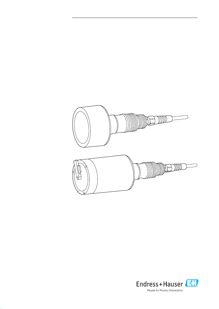
Turbimax CUS71D
Ultrasonic interface sensor
Page 2

Page 3

Turbimax CUS71D Table of contents
Table of contents
1 About this document ........... 4
1.1 Warnings ........................... 4
1.2 Symbols used ........................ 4
2 Basic safety instructions ....... 5
2.1 Requirements for personnel ........... 5
2.2 Designated use ...................... 5
2.3 Workplace safety .................... 6
2.4 Operational safety ................... 7
2.5 Product safety ....................... 7
2.6 IT security .......................... 7
3 Product description ............. 8
3.1 Product design ....................... 8
4 Incoming acceptance and
product identification .......... 8
4.1 Incoming acceptance ................. 8
4.2 Product identification ................. 9
4.3 Scope of delivery ..................... 9
4.4 Certificates and approvals ............ 10
5 Installation .................... 11
5.1 Installation conditions ............... 11
5.2 Mounting the sensor ................ 14
5.3 Post-installation check ............... 17
11 Repairs ......................... 23
11.1 General notes ...................... 23
11.2 Spare parts ........................ 23
11.3 Return ............................ 23
11.4 Disposal ........................... 24
12 Accessories .................... 25
12.1 Assemblies ........................ 25
12.2 Holder ............................ 26
12.3 Cable extension ..................... 27
13 Technical data ................. 27
13.1 Input .............................. 27
13.2 Performance characteristics .......... 27
13.3 Environment ....................... 28
13.4 Process ............................ 28
13.5 Mechanical construction ............. 28
Index ................................. 29
6 Electrical connection .......... 17
6.1 Connecting the sensor ............... 17
6.2 Post-connection check ............... 20
7 Commissioning ................ 20
7.1 Preparatory steps ................... 20
8 Operation ...................... 20
8.1 Sensor monitoring .................. 20
8.2 Cyclic cleaning ...................... 21
8.3 Automatic wiper function ............ 21
9 Diagnostics and
troubleshooting ............... 21
9.1 General troubleshooting ............. 21
10 Maintenance .................. 22
10.1 Maintenance tasks .................. 22
Endress+Hauser 3
Page 4

About this document Turbimax CUS71D
1 About this document
1.1 Warnings
Structure of information Meaning
DANGER
L
Causes (/consequences)
If necessary, Consequences of noncompliance (if applicable)
Corrective action
‣
WARNING
L
Causes (/consequences)
If necessary, Consequences of noncompliance (if applicable)
Corrective action
‣
CAUTION
L
Causes (/consequences)
If necessary, Consequences of noncompliance (if applicable)
Corrective action
‣
NOTICE
Cause/situation
If necessary, Consequences of noncompliance (if applicable)
Action/note
‣
This symbol alerts you to a dangerous situation.
Failure to avoid the dangerous situation will result in a fatal or serious injury.
This symbol alerts you to a dangerous situation.
Failure to avoid the dangerous situation can result in a fatal or serious injury.
This symbol alerts you to a dangerous situation.
Failure to avoid this situation can result in minor or more serious injuries.
This symbol alerts you to situations which may result in damage to property.
1.2 Symbols used
Symbol Meaning
Additional information, tips
Permitted or recommended
Not permitted or not recommended
Reference to device documentation
Reference to page
Reference to graphic
Result of a step
4 Endress+Hauser
Page 5
Turbimax CUS71D Basic safety instructions
1.2.1 Symbols on the device
Symbol Meaning
Reference to device documentation
2 Basic safety instructions
2.1 Requirements for personnel
• Installation, commissioning, operation and maintenance of the measuring system may be
carried out only by specially trained technical personnel.
• The technical personnel must be authorized by the plant operator to carry out the specified
activities.
• The electrical connection may be performed only by an electrical technician.
• The technical personnel must have read and understood these Operating Instructions and
must follow the instructions contained therein.
• Faults at the measuring point may only be rectified by authorized and specially trained
personnel.
Repairs not described in the Operating Instructions provided must be carried out only
directly at the manufacturer's site or by the service organization.
2.2 Designated use
CUS71D is a sensor designed for interface measurement in water and wastewater.
The sensor is particularly suited for use in the following applications:
• Wastewater treatment: primary clarifier, sludge thickener, secondary clarifier
• Water treatment: sedimentation tank after flocculant dosage, sludge height in contact
sludge processes
• Static separation processes: with/without slow stirring and without introduction of air
Use of the device for any purpose other than that described, poses a threat to the safety of
people and of the entire measuring system and is therefore not permitted.
The manufacturer is not liable for damage caused by improper or non-designated use.
NOTICE
Applications outside specifications!
Incorrect measurements, malfunctions and even measuring point failure could result
Use the product only in accordance with the specifications.
‣
Pay attention to the technical data on the nameplate.
‣
Endress+Hauser 5
Page 6

Basic safety instructions Turbimax CUS71D
2.3 Workplace safety
As the user, you are responsible for complying with the following safety conditions:
• Installation guidelines
• Local standards and regulations
Electromagnetic compatibility
• The product has been tested for electromagnetic compatibility in accordance with the
applicable European standards for industrial applications.
• The electromagnetic compatibility indicated applies only to a product that has been
connected in accordance with these Operating Instructions.
6 Endress+Hauser
Page 7

Turbimax CUS71D Basic safety instructions
2.4 Operational safety
Before commissioning the entire measuring point:
1. Verify that all connections are correct.
2. Ensure that electrical cables and hose connections are undamaged.
3. Do not operate damaged products, and protect them against unintentional operation.
4. Label damaged products as defective.
During operation:
If faults cannot be rectified:
‣
products must be taken out of service and protected against unintentional operation.
2.5 Product safety
The product is designed to meet state-of-the-art safety requirements, has been tested, and
left the factory in a condition in which it is safe to operate. The relevant regulations and
European standards have been observed.
2.6 IT security
We only provide a warranty if the device is installed and used as described in the Operating
Instructions. The device is equipped with security mechanisms to protect it against any
inadvertent changes to the device settings.
IT security measures in line with operators' security standards and designed to provide
additional protection for the device and device data transfer must be implemented by the
operators themselves.
Endress+Hauser 7
Page 8

Product description Turbimax CUS71D
3 Product description
3.1 Product design
The sensor is designed for continuous in-situ determination of interfaces.
The sensor includes all necessary modules:
• Power supply
• The ultrasonic source emits the measurement signals.
• The ultrasonic receiver receives the measurement signals, digitalizes the signals and
converts them to a measurement value.
• The sensor microcontroller controls the internal operations and data transmission.
The preconfigured sensor can be used at a measuring point.
3.1.1 Measuring principle
A piezoelectric crystal is enclosed in a flat cylindrical plastic housing. When the crystal is
excited by an electrical voltage, it generates a sonar signal. This causes ultrasonic waves to be
transmitted at a frequency of approx. 650 kHz and at an angle of 6° to scan the separation
zones.
The measured variable is the time the transmitted ultrasonic signal needs to reach the solid
particles in the separation zone and return to the receiver. The separation zone is computed
after the maximum slope and the maximum signal amplitude.
A sensor version featuring a wiper is available to reliably avoid the buildup of deposit on the
sensor membrane.
4 Incoming acceptance and product identification
4.1 Incoming acceptance
1. Verify that the packaging is undamaged.
Notify the supplier of any damage to the packaging.
Keep the damaged packaging until the issue has been resolved.
2. Verify that the contents are undamaged.
Notify the supplier of any damage to the delivery contents.
Keep the damaged goods until the issue has been resolved.
3. Check that the delivery is complete and nothing is missing.
Compare the shipping documents with your order.
4. Pack the product for storage and transportation in such a way that it is protected
against impact and moisture.
The original packaging offers the best protection.
Make sure to comply with the permitted ambient conditions.
If you have any questions, please contact your supplier or your local Sales Center.
8 Endress+Hauser
Page 9

Turbimax CUS71D Incoming acceptance and product identification
4.2 Product identification
4.2.1 Nameplate
The nameplate provides you with the following information on your device:
• Manufacturer identification
• Order code
• Extended order code
• Serial number
• Ambient and process conditions
• Safety information and warnings
Compare the information on the nameplate with the order.
‣
4.2.2 Product identification
Interpreting the order code
The order code and serial number of your product can be found in the following locations:
• On the nameplate
• In the delivery papers
Obtaining information on the product
1. Go to www.endress.com.
2. Call up the site search (magnifying glass).
3. Enter a valid serial number.
4. Search.
The product structure is displayed in a popup window.
5. Click on the product image in the popup window.
A new window (Device Viewer) opens. All of the information relating to your
device is displayed in this window as well as the product documentation.
Manufacturer address
Endress+Hauser Conducta GmbH+Co. KG
Dieselstraße 24
D-70839 Gerlingen
4.3 Scope of delivery
The delivery comprises:
• 1 Turbimax CUS71D sensor, version as ordered
• 1 set of Operating Instructions BA00490C/07/EN
If you have any queries:
‣
Please contact your supplier or local sales center.
Endress+Hauser 9
Page 10

Incoming acceptance and product identification Turbimax CUS71D
4.4 Certificates and approvals
4.4.1
mark
The product meets the requirements of the harmonized European standards. As such, it
complies with the legal specifications of the EU directives. The manufacturer confirms
successful testing of the product by affixing to it the mark.
4.4.2 EAC
The product has been certified according to guidelines TP TC 004/2011 and TP TC 020/2011
which apply in the European Economic Area (EEA). The EAC conformity mark is affixed to the
product.
4.4.3 Electromagnetic compatibility
Interference emission and interference immunity: Industrial environment as per
• EN 61326-1:2013
• EN 61326-2-3:2013
• NAMUR NE21: 2012
10 Endress+Hauser
Page 11
Turbimax CUS71D Installation
A
B
C
D
E
6°
F
5 Installation
5.1 Installation conditions
5.1.1 Installation instructions
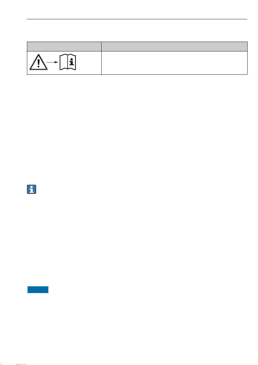
Basin configuration
A0031574
1 Basin configuration
A Sensor
B 50 cm (1.64 ft) Minimum distance between sensor and basin rim
C Fixed reference point, e.g. surface of water, basin rim, bridge/walkway etc.
D Sensor offset
E Basin depth
F Opening angle of ultrasonic cone 6°
Installation instructions
Find a suitable installation position for the sensor in the basin. Take the following points into
consideration when selecting the installation position:
1. Ensure the distance from the basin rim is at least 50 cm (1.64 ft) (the sensor emits
ultrasonic waves in a conical pattern).
There should not be any conduits or basin wall protrusions in the measuring range
below the sensor. Scraper units that are only temporarily in this area are permitted.
Endress+Hauser 11
Page 12

Installation Turbimax CUS71D
Ø 74 (2.9)
Ø 75 (3.0)
Ø 33.7(1.3)
20.5
(0.8)
17
(0.7)
15
(0.6)
G1"
NPT 3/4"
43 (1.7)
68 (2.7)
60.5 (2.4)
AF 27
Ø 34.7(1.4)
Ø74(2.9)
110
(
4
.
3
)
8
135
(5.3)
6
0.5(2.4)
Ø75(3.0)
Ø34.7
(1.4)
17
(0.7)
20.5
(0.8)
1
5
(0.6)
Ø 33.7 (1.3)
G1"
NPT 3/4"
AF 27
2. Mount the sensor so that it is straight and parallel to the basin wall (measured value
offset).
Do not install the sensor in zones where air bubbles, turbulence, high
concentrations of turbid material and suspended matter, or foam formation occur
(e.g. inlet).
3. Using a dip pipe, install the sensor at least 20 cm (0.66 ft) beneath the surface of the
water.
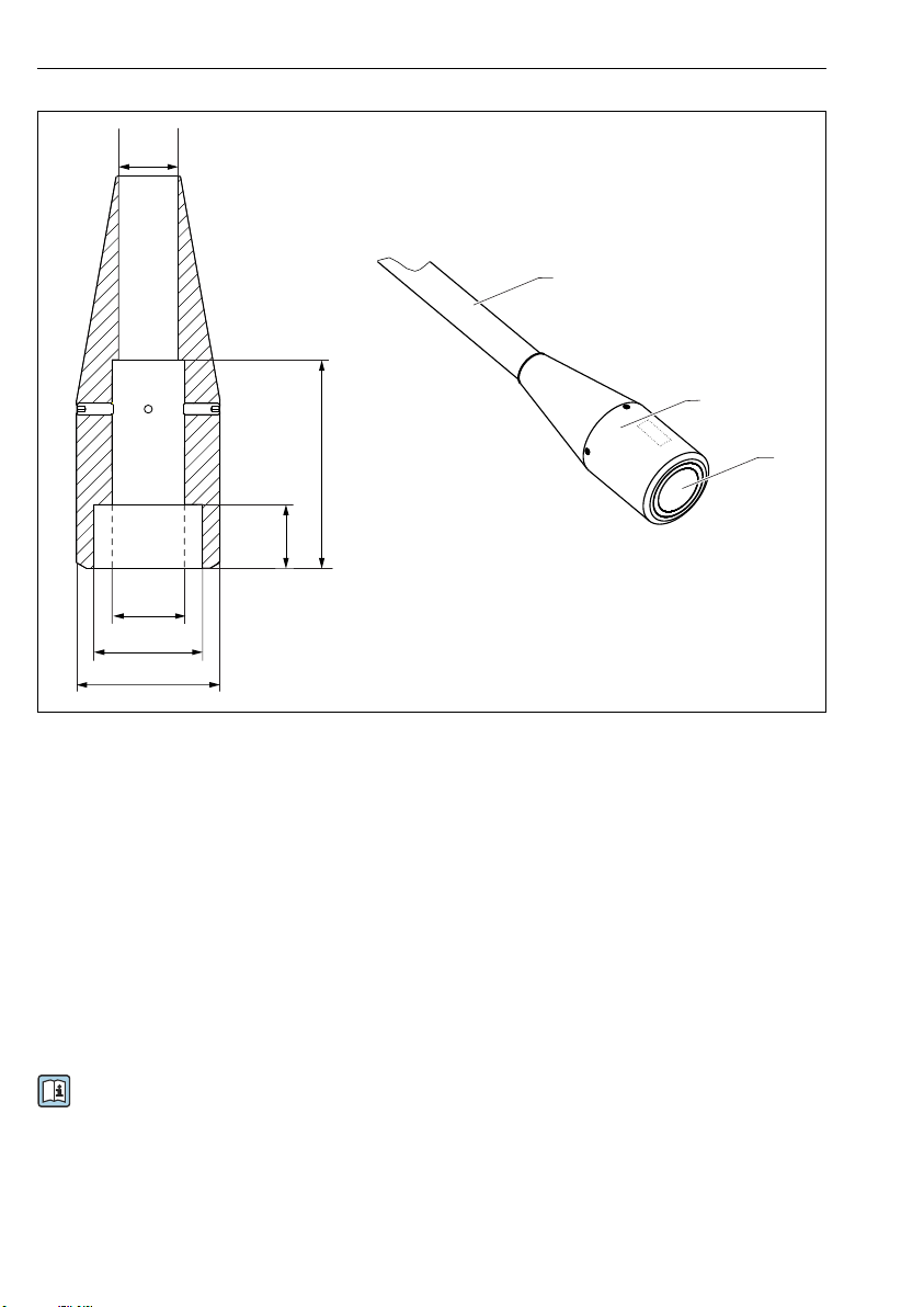
5.1.2 Dimensions
A0036897
3 Dimensions for sensor with wiper.
Dimensions: mm (in)
2 Dimensions for standard sensor.
Dimensions: mm (in)
12 Endress+Hauser
A0036898
Page 13

Turbimax CUS71D Installation
¹/₃
1
2
3
4
5
11
12
13
14
A
B
²/₃
¹/₃
²/₃
Circular clarifier
A0031579
4 Basin configuration in circular clarifiers
A View from above B Cross-section
1 Surface skimmer 11 Sensor
2 Bridge/walkway 12 Rail
3 Sensor position range 13 Surface skimmer
4 Floor rake 14 Floor rake
5 Direction of rake movement
Endress+Hauser 13
Page 14

Installation Turbimax CUS71D
5.2 Mounting the sensor
5.2.1 Measuring system
A complete measuring system comprises:
• Turbimax CUS71D ultrasonic sensor
• Liquiline CM44x multi-channel transmitter
and is optionally delivered with the following accessories:
• A weather protection cover CYY101
• A Flexdip CYH112 holder
• A fixed or rotatable Flexdip CYA112 dip pipe
14 Endress+Hauser
Page 15
Turbimax CUS71D Installation
1
2
3
4
1
5
90°
6
7
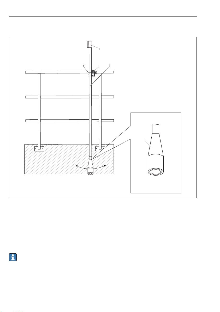
5 Ultrasonic sensor with basin holder system and multi-channel transmitter
1 Flexdip CYH112 holder
2 Liquiline CM44x multi-channel transmitter
3 Protective cover
4 Flexdip CYA112 assembly
5 Turbimax CUS71D ultrasonic sensor
6 Vertical from all sides
7 Splash protection cap
A0031577
Endress+Hauser 15
Page 16
Installation Turbimax CUS71D
1
2
3
4
5
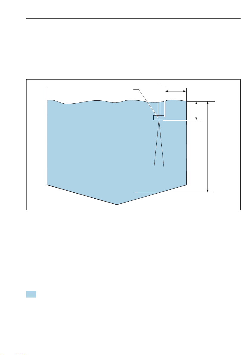
5.2.2 Measuring system with pendulum holder
6 Measuring system with pendulum holder
1 Flexdip CYH112 holder (cross clamp)
2 Flexdip CYH112 holder (pendulum holder)
3 Flexdip CYA112 assembly with CUS71D
4 PVC sensor protector
5 Splash protection cap
A0031578
The PVC sensor protector protects the ultrasonic sensor from being damaged by the surface
skimmer.
In the case of surface skimmers, only use the sensor without a wiper and with a PVC
sensor protector (→ 26).
16 Endress+Hauser
Page 17

Turbimax CUS71D Electrical connection
5.3 Post-installation check
Check the following:
• Are the sensor and cable undamaged?
• Is the cap undamaged?
• Is the orientation correct?
• Is the sensor installed in an assembly and not suspended from the cable?
Avoid the penetration of moisture by fitting the protective cap on the assembly.
6 Electrical connection
WARNING
L
Device is live!
Incorrect connection may result in injury or death!
The electrical connection may be performed only by an electrical technician.
‣
The electrical technician must have read and understood these Operating Instructions and
‣
must follow the instructions contained therein.
Prior to commencing connection work, ensure that no voltage is present on any cable.
‣
6.1 Connecting the sensor
1. Connect one sensor (maximum) to the Liquiline CM442. Connect up to 4 sensors to the
Liquiline CM444 and CM448 transmitters.
Endress+Hauser 17
Page 18
Electrical connection Turbimax CUS71D
N L
43 42 41
86 85 86
85
98 97 88 87
32 31
32 31
PK
GY
GN
YE
Sensor
PE
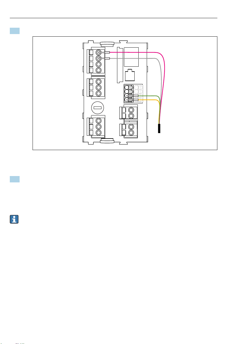
2. Connect the fixed cable of the sensor to the Liquiline CM44x transmitter as follows:
A0034802
7 Sensor connection
The maximum cable length is 100 m (328 ft).
3. Use the following accessories to extend the sensor cable if necessary:
• CYK11 measuring cable with ferrules → 27
• Cable/cable junction box → 27
6.1.1 Connecting the cable shield
Only use terminated original cables where possible. The sensor cables must be shielded
cables.
18 Endress+Hauser
Page 19

Turbimax CUS71D Electrical connection
1
2
3
4
Cable sample (does not necessarily correspond to the original cable supplied)
8 Terminated cable
1 Outer shield (exposed)
2 Cable cores with ferrules
3 Cable sheath (insulation)
9 Insert the cable
4 Grounding clip
10 Tighten screw (2 Nm)
The cable shield is grounded by the
grounding clip.
Endress+Hauser 19
Page 20

Commissioning Turbimax CUS71D
6.2 Post-connection check
Device condition and specifications Notes
Are the sensor, assembly, or cables free from damage on the outside? Visual inspection
Electrical connection Notes
Are the mounted cables strain-relieved and not twisted?
Is a sufficient length of the cable cores stripped, and are the cores
positioned in the terminal correctly?
Are all the screw terminals properly tightened? Tighten
Are all cable entries mounted, tightened and leak-tight? For lateral cable entries, make sure the cables
Are all cable entries installed downwards or mounted laterally?
Check the fit (by pulling gently)
loop downwards to allow water to drip off
7 Commissioning
7.1 Preparatory steps
7.1.1 Factory settings
The sensor is preconfigured on leaving the factory. Once the installation parameters have
been adjusted, the sensor is ready for use in a wide range of applications without further
adjustments. The factory settings cannot be deleted and can be restored at any time.
Enter the installation parameters at the Liquiline CM44x transmitter.
‣
For more information, please refer to the Operating Instructions of the transmitter.
8 Operation
8.1 Sensor monitoring
The acoustic signals are continuously monitored and analyzed for plausibility. If
inconsistencies occur, an error message is output via the transmitter.
In addition, the following fault conditions are detected by the sensor diagnostics of Liquiline
CM44x:
• Implausibly high or low measured values
• Disturbed regulation due to incorrect measured values
20 Endress+Hauser
Page 21

Turbimax CUS71D Diagnostics and troubleshooting
8.2 Cyclic cleaning
Cyclic cleaning is available for ultrasonic sensors with an integrated wiper. The wiper interval
is set to 240 minutes at the factory.
8.3 Automatic wiper function
Sensor versions with a wiper have an integrated automatic wiper function. The wiper starts as
soon as the sensor stops receiving a signal. This happens when the sensor membrane is
fouled, for example.
• The wiper wipes twice every 5 minutes for a maximum of 3 runs.
• If the sensor does not receive a signal after 30 minutes, the sensor triggers the diagnostic
message 172 Echo loss at the transmitter.
9 Diagnostics and troubleshooting
9.1 General troubleshooting
When troubleshooting, the entire measuring point must be taken into account:
• Transmitter
• Electrical connections and cables
• Assembly
• Sensor
The possible causes of error in the following table refer primarily to the sensor.
Display
No display, no sensor
reaction
Display value too high
or too low
Display value
fluctuating greatly
Pay attention to the troubleshooting information in the Operating Instructions for the
transmitter. Check the transmitter if necessary.
Endress+Hauser 21
Check Solution
• Mains voltage connected to the
transmitter
• Sensor connected correctly
• Deposit buildup on sensor
membrane
• Check sensor/channel configuration
• Basin configuration
• Check sensor installation
• Check mounting location
• Deposit buildup on sensor
membrane
• Basin configuration
• Apply line voltage
• Make the right
connection
• Clean sensor
• Assign sensor
Configure sensor
• Select a different
mounting location
• Clean sensor
• Configure sensor
Page 22

Maintenance Turbimax CUS71D
10 Maintenance
You must perform maintenance tasks at regular intervals.
‣
We recommend setting the maintenance times in advance in an operations journal or log.
The maintenance cycle primarily depends on the following:
• The system
• The installation conditions
• The medium in which measurement takes place
CAUTION
L
Risk of injury from acids or medium, damage to clothing and equipment!
Switch off the cleaning unit before removing the sensor from the medium.
‣
Wear protective goggles and safety gloves.
‣
Clean away splashes on clothes and other objects.
‣
10.1 Maintenance tasks
10.1.1 Cleaning the sensor Sensor without wiper
Sensor fouling can affect the measurement results and even cause a malfunction.
Clean the sensor, and the underside of the sensor in particular, at regular intervals to
‣
ensure reliable measurement.
The frequency and intensity of the cleaning process depend on the medium.
Clean the sensor:
• As specified in the maintenance schedule
• Before returning it for repair
After cleaning, rinse the sensor with copious amounts of water.
‣
Sensor with wiper
The wiping interval is preselected via the software. The cleaning interval depends on the
medium.
We recommend you replace the wiper blade every 6 to 12 months.
22 Endress+Hauser
Page 23

Turbimax CUS71D Repairs
11 Repairs
11.1 General notes
Only use spare parts from Endress + Hauser to guarantee the safe and stable functioning of
‣
the device.
Detailed information on the spare parts is available at:
www.endress.com/device-viewer
11.2 Spare parts
The following spare part kits are available for the sensor with a wiper:
Name of spare parts kit Order code
Wiper blade with plastic housing and washer 71156817
Motor assembly
• Gear motor
• Motor cable
Coupler assembly
• Set screw
• Coupling
Shaft assembly
• Socket
• O-ring
• Shaft
• Washer
71156830
71156832
71156833
For more detailed information on spare parts kits, please refer to the "Spare Part Finding Tool"
on the Internet:
www.products.endress.com/spareparts_consumables
11.3 Return
The product must be returned if repairs or a factory calibration are required, or if the wrong
product was ordered or delivered. As an ISO-certified company and also due to legal
regulations, Endress+Hauser is obliged to follow certain procedures when handling any
returned products that have been in contact with medium.
To ensure the swift, safe and professional return of the device:
Refer to the website www.endress.com/support/return-material for information on the
‣
procedure and conditions for returning devices.
Endress+Hauser 23
Page 24

Repairs Turbimax CUS71D
11.4 Disposal
The device contains electronic components. and must therefore be disposed of in accordance
with regulations on the disposal of electronic waste.
Observe the local regulations.
‣
24 Endress+Hauser
Page 25

Turbimax CUS71D Accessories
12 Accessories
The following are the most important accessories available at the time this documentation
was issued.
For accessories not listed here, please contact your Service or Sales Center.
‣
12.1 Assemblies
FlexdipCYA112
• Immersion assembly for water and wastewater
• Modular assembly system for sensors in open basins, channels and tanks
• Material: PVC or stainless steel
• Product Configurator on the product page: www.endress.com/cya112
Technical Information TI00432C
PVC sensor protector for pendulum holder
• The PVC sensor protector protects the CUS71D ultrasonic sensor from being damaged by
the surface skimmer.
• Available for order via the product structure
• Can be ordered individually via order number: 71404869
Only use the PVC sensor protector for the sensor version without a wiper.
Endress+Hauser 25
Page 26
Accessories Turbimax CUS71D
Ø 50
(2.0)
Ø 76 (3)
Ø 99 (3.9)
44
(1.7)
144 (5.7)
Ø 41
(1.6)
1
2
3
A0037314
11 PVC sensor protector for CUS71D. Dimensions: mm (in)
1 CYA112 assembly
2 PVC sensor protector
3 CUS71D ultrasonic sensor
12.2 Holder
Flexdip CYH112
• Modular holder system for sensors and assemblies in open basins, channels and tanks
• For Flexdip CYA112 water and wastewater assemblies
• Can be affixed anywhere: on the ground, on the capstone, on the wall or directly onto
railings.
• Stainless steel version
• Product Configurator on the product page: www.endress.com/cyh112
Technical Information TI00430C
26 Endress+Hauser
Page 27

Turbimax CUS71D Technical data
12.3 Cable extension
Memosens data cable CYK11
• Extension cable for digital sensors with Memosens protocol
• Product Configurator on the product page: www.endress.com/cyk11
Technical Information TI00118C
Junction box, cable/cable
• Material: aluminum, painted
• Cable extension: Memosens sensors, Liquiline
• Order number: 71145499
13 Technical data
13.1 Input
13.1.1 Measured values
Interface
13.1.2 Measuring ranges
0.3 to 10 m (1 to 32 ft)
13.2 Performance characteristics
13.2.1 Reference operating conditions
20 °C (68 °F), 1013 hPa
13.2.2 Maximum measured error
± 2 % of end of measuring range
13.2.3 Measured value resolution
± 0.3 % with end of measuring range up to 3 m (9.8 ft)
± 0.15 % with end of measuring range from 3 m (9.8 ft)
13.2.4 Measuring interval
Sensor-internal
Sensor to transmitter 12 seconds
13.2.5 Calibration
The sensor is factory-configured when delivered.
Endress+Hauser 27
Configurable
Page 28

Technical data Turbimax CUS71D
13.3 Environment
13.3.1 Storage temperature
–20 to 50 °C (–4 to 120 °F)
13.3.2 Degree of protection
IP 68 (1 m (3.3 ft) water column over 60 days, 1 mol/l KCl)
13.4 Process
13.4.1 Process temperature
1 to 50 °C (34 to 122 °F)
13.4.2 Process pressure
Standard version:
Version with wiper: 0 to 0.3 bar (0 to 4.4 psi)
0 to 6 bar (0 to 87 psi)
13.5 Mechanical construction
13.5.1 Dimensions
→ Section "Installation"
13.5.2 Weight
Standard sensor:
Sensor with wiper: 1.25 kg (2.75 lb)
13.5.3 Materials
Sensor:
Wiper: EPDM
Housing: Polyamide
13.5.4 Process connections
G1 and NPT ¾"
1.02 kg (2.25 lb)
ABS and epoxy resin
28 Endress+Hauser
Page 29

Turbimax CUS71D Index
Index
A
Accessories ..................... 25
Approvals ...................... 10
Assemblies ..................... 25
C
Cable extension ...................27
Certificates ..................... 10
Cleaning .......................22
Commissioning ...................20
Cyclic cleaning ................... 21
D
Designated use ....................5
Diagnostics ..................... 21
Dimensions ..................... 12
Disposal ....................... 24
E
Electrical connection ................17
F
Factory settings ...................20
H
Holder ........................ 26
I
Incoming acceptance ................ 8
Installation ..................... 11
IT security .......................7
Product description ................. 8
Product design .................... 8
Product identification ................ 9
Product safety .................... 7
R
Repairs ........................23
Return ........................ 23
S
Safety instructions ..................5
Scope of delivery ...................9
Sensor cleaning ...................22
Sensor monitoring ................. 20
Spare parts ..................... 23
Symbols ........................ 4
T
Technical data ................... 27
Troubleshooting .................. 21
W
Warnings ....................... 4
Wiper function ................... 21
Wiring ........................17
Workplace safety .................. 6
M
Maintenance .................... 22
Measuring principle .................8
Measuring system ................. 14
Pendulum holder ...............16
N
Nameplate ...................... 9
O
Operational safety ..................7
P
Post-connection check ...............20
Endress+Hauser 29
Page 30

Page 31

Page 32

*71415440*
71415440
www.addresses.endress.com
 Loading...