

Page 1
BA01275C/07/EN/06.20
71473306
2020-03-16
Products Solutions Services
Operating Instructions
Turbimax CUS52D
Turbidity sensor
Page 2

Page 3

Turbimax CUS52D Table of contents
Table of contents
1 About this document ................ 4
1.1 Warnings ............................ 4
1.2 Symbols used .......................... 4
1.3 Symbols on the device ................... 4
2 Basic safety instructions ............ 5
2.1 Requirements for personnel ............... 5
2.2 Designated use ........................ 5
2.3 Workplace safety ....................... 5
2.4 Operational safety ...................... 6
2.5 Product safety ......................... 6
3 Product description ................. 7
3.1 Product design ......................... 7
4 Incoming acceptance and product
identification ....................... 8
4.1 Incoming acceptance .................... 8
4.2 Product identification .................... 8
4.3 Scope of delivery ....................... 9
4.4 Certificates and approvals ................ 9
11.3 Return .............................. 37
11.4 Disposal ............................ 37
12 Accessories ....................... 38
12.1 Assemblies .......................... 38
12.2 Holder .............................. 39
12.3 Mounting material ..................... 39
12.4 Compressed air cleaning ................ 39
12.5 Ultrasonic cleaning .................... 40
12.6 Bubble trap .......................... 40
12.7 Solid state reference ................... 41
12.8 Calibration vessel ...................... 41
13 Technical data .................... 42
13.1 Input ............................... 42
13.2 Performance characteristics .............. 42
13.3 Environment ......................... 43
13.4 Process ............................. 43
13.5 Mechanical construction ................ 44
Index .................................. 45
5 Installation ....................... 10
5.1 Installation conditions .................. 10
5.2 Mounting the sensor ................... 15
5.3 Post-installation check .................. 20
6 Electrical connection .............. 21
6.1 Connecting the sensor .................. 21
6.2 Ensuring the degree of protection .......... 22
6.3 Post-connection check .................. 22
7 Commissioning .................... 23
7.1 Function check ....................... 23
8 Operation ......................... 24
8.1 Adapting the measuring device to the process
conditions ........................... 24
9 Diagnostics and troubleshooting ... 35
9.1 General troubleshooting ................. 35
10 Maintenance ...................... 36
10.1 Maintenance tasks ..................... 36
11 Repair ............................ 37
11.1 General information ................... 37
11.2 Spare parts .......................... 37
Endress+Hauser 3
Page 4
About this document Turbimax CUS52D
1 About this document
1.1 Warnings
Structure of information Meaning
DANGER
L
Causes (/consequences)
If necessary, Consequences of
non-compliance (if applicable)
Corrective action
‣
WARNING
L
Causes (/consequences)
If necessary, Consequences of
non-compliance (if applicable)
Corrective action
‣
CAUTION
L
Causes (/consequences)
If necessary, Consequences of
non-compliance (if applicable)
Corrective action
‣
NOTICE
Cause/situation
If necessary, Consequences of
non-compliance (if applicable)
Action/note
‣
This symbol alerts you to a dangerous situation.
Failure to avoid the dangerous situation will result in a fatal or serious
injury.
This symbol alerts you to a dangerous situation.
Failure to avoid the dangerous situation can result in a fatal or serious
injury.
This symbol alerts you to a dangerous situation.
Failure to avoid this situation can result in minor or more serious injuries.
This symbol alerts you to situations which may result in damage to
property.
1.2 Symbols used
Symbol Meaning
Additional information, tips
Permitted or recommended
Not permitted or not recommended
Reference to device documentation
Reference to page
Reference to graphic
Result of a step
1.3 Symbols on the device
Symbol Meaning
Reference to device documentation
4 Endress+Hauser
Page 5

Turbimax CUS52D Basic safety instructions
2 Basic safety instructions
2.1 Requirements for personnel
• Installation, commissioning, operation and maintenance of the measuring system may
be carried out only by specially trained technical personnel.
• The technical personnel must be authorized by the plant operator to carry out the
specified activities.
• The electrical connection may be performed only by an electrical technician.
• The technical personnel must have read and understood these Operating Instructions
and must follow the instructions contained therein.
• Faults at the measuring point may only be rectified by authorized and specially trained
personnel.
Repairs not described in the Operating Instructions provided must be carried out only
directly at the manufacturer's site or by the service organization.
2.2 Designated use
CUS52D is a sensor for measuring turbidity and low solids content in drinking water and
process water applications.
The sensor is particularly suited for use in the following applications:
• Final turbidity measurement in outlet of waterworks
• Turbidity measurement in inlet of waterworks
• Turbidity measurement at all process stages
• Turbidity measurement for filter monitoring and filter backwashing
• Turbidity measurement in drinking water networks
• Turbidity measurement in media with high salinity (plastic sensor only)
Use of the device for any purpose other than that described, poses a threat to the safety of
people and of the entire measuring system and is therefore not permitted.
The manufacturer is not liable for damage caused by improper or non-designated use.
2.3 Workplace safety
As the user, you are responsible for complying with the following safety conditions:
• Installation guidelines
• Local standards and regulations
Electromagnetic compatibility
• The product has been tested for electromagnetic compatibility in accordance with the
applicable international standards for industrial applications.
• The electromagnetic compatibility indicated applies only to a product that has been
connected in accordance with these Operating Instructions.
Endress+Hauser 5
Page 6

Basic safety instructions Turbimax CUS52D
2.4 Operational safety
Before commissioning the entire measuring point:
1. Verify that all connections are correct.
2. Ensure that electrical cables and hose connections are undamaged.
3. Do not operate damaged products, and protect them against unintentional operation.
4. Label damaged products as defective.
During operation:
If faults cannot be rectified:
‣
products must be taken out of service and protected against unintentional operation.
2.5 Product safety
2.5.1 State-of-the-art technology
The product is designed to meet state-of-the-art safety requirements, has been tested, and
left the factory in a condition in which it is safe to operate. The relevant regulations and
international standards have been observed.
6 Endress+Hauser
Page 7
Turbimax CUS52D Product description
1
2
90° ± 2.5°
20° - 30°
3 Product description
3.1 Product design
The sensor with the 40 mm (1.57 in) diameter can be operated directly and completely in
the process without the need for further sampling (in-situ).
The sensor includes all necessary modules:
• Power supply
• Light sources
• Detectors
Detectors record the measuring signals, digitize them and process them into a measured
value.
• Sensor microcontroller
This is responsible for controlling internal processes and transmitting data.
All data - including the calibration data - are stored in the sensor. The sensor can be
precalibrated and used at a measuring point, calibrated externally, or used for several
measuring points with different calibrations.
A0030692
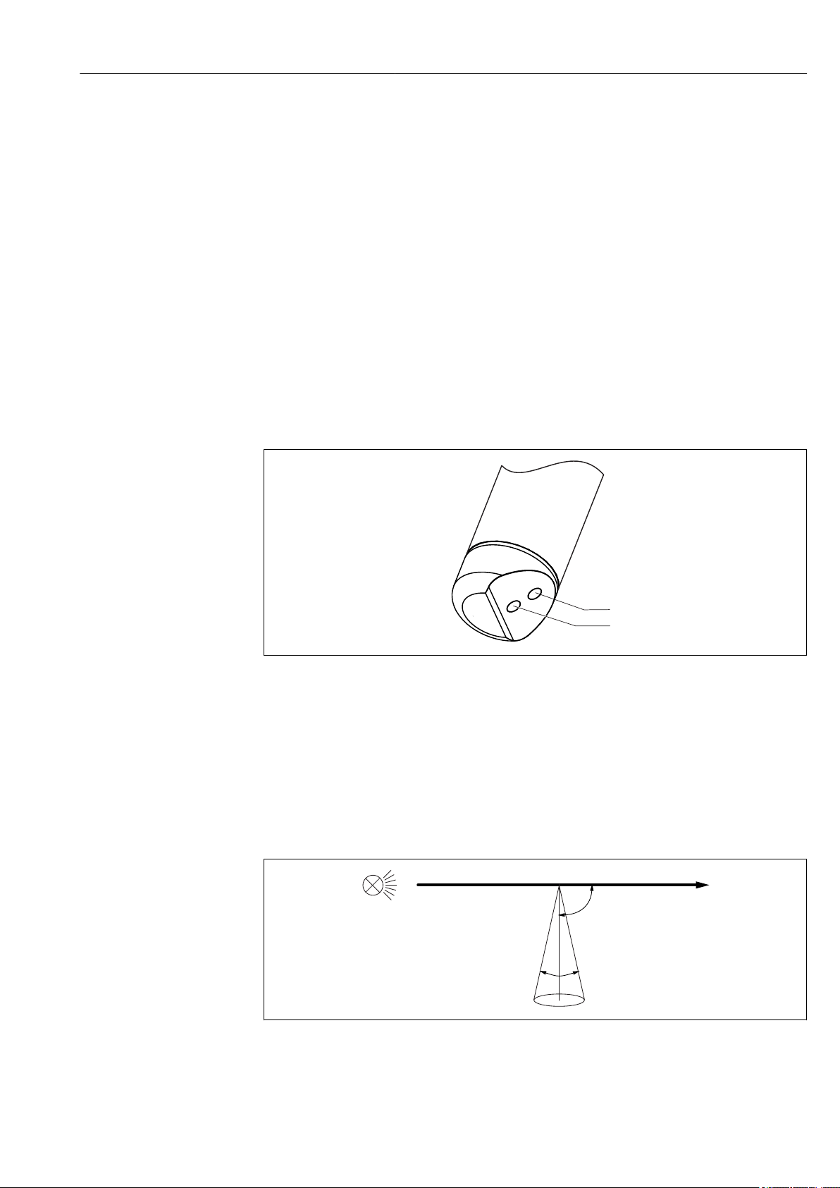
1 Arrangement of light source and light receiver
1 Light receiver
2 Light source
3.1.1 Measuring principle
The sensor works using the 90° light scattering principle in accordance with ISO 7027 and
meets all the requirements of this standard (no divergence and a maximum convergence
of 1.5°). The ISO 7027 standard is obligatory for turbidity measurements in the drinking
water sector.
A0030701
2 Measurement in accordance with ISO 7027
Measurement is done using a wavelength of 860 nm.
Endress+Hauser 7
Page 8

Incoming acceptance and product identification Turbimax CUS52D
4 Incoming acceptance and product
identification
4.1 Incoming acceptance
1. Verify that the packaging is undamaged.
Notify the supplier of any damage to the packaging.
Keep the damaged packaging until the issue has been resolved.
2. Verify that the contents are undamaged.
Notify the supplier of any damage to the delivery contents.
Keep the damaged goods until the issue has been resolved.
3. Check that the delivery is complete and nothing is missing.
Compare the shipping documents with your order.
4. Pack the product for storage and transportation in such a way that it is protected
against impact and moisture.
The original packaging offers the best protection.
Make sure to comply with the permitted ambient conditions.
If you have any questions, please contact your supplier or your local Sales Center.
4.2 Product identification
4.2.1 Nameplate
The nameplate provides you with the following information on your device:
• Manufacturer identification
• Order code
• Extended order code
• Serial number
• Safety information and warnings
Compare the information on the nameplate with the order.
‣
4.2.2 Product identification
The order code and serial number of your product can be found in the following locations:
• On the nameplate
• In the delivery papers
Obtaining information on the product
1. Go to www.endress.com.
2. Call up the site search (magnifying glass).
3. Enter a valid serial number.
4. Search.
The product structure is displayed in a popup window.
5. Click on the product image in the popup window.
A new window (Device Viewer) opens. All of the information relating to your
device is displayed in this window as well as the product documentation.
8 Endress+Hauser
Page 9

Turbimax CUS52D Incoming acceptance and product identification
4.2.3 Manufacturer's address
Endress+Hauser Conducta GmbH+Co. KG
Dieselstraße 24
D-70839 Gerlingen
4.3 Scope of delivery
The delivery comprises:
• 1 sensor, version as ordered
• 1 Operating Instructions BA01275C
4.4 Certificates and approvals
4.4.1 Electromagnetic compatibility
Interference emission and interference immunity as per
• EN 61326-1:2013
• EN 61326-2-3:2013
• NAMUR NE21: 2012
4.4.2 mark
The product meets the requirements of the harmonized European standards. As such, it
complies with the legal specifications of the EU directives. The manufacturer confirms
successful testing of the product by affixing to it the mark.
4.4.3 ISO 7027
The measurement method used in the sensor corresponds to the nephelometric turbidity
method according to ISO 7027-1:2016.
4.4.4 EAC
The product has been certified according to guidelines TP TC 004/2011 and TP TC
020/2011 which apply in the European Economic Area (EEA). The EAC conformity mark
is affixed to the product.
4.4.5 Marine approvals
A selection of sensors have type approval for marine applications, issued by the following
classification societies: ABS (American Bureau of Shipping), BV (Bureau Veritas), DNV-GL
(Det Norske Veritas-Germanischer Lloyd) and LR (Lloyd’s Register). Details of the order
codes of the approved sensors, and the installation and ambient conditions, are provided in
the relevant certificates for marine applications on the product page on the Internet.
Endress+Hauser 9
Page 10
Installation Turbimax CUS52D
Ø 40
(1.57)
NPT ¾“
G1
237.5 (9.35)
82.7 (3.26)
2 (0.08)
20.5 (0.81)
18.5 (0.73)
12.5
(0.49)
13.5
(0.53)
20.5
(0.81)
15
(0.59)
5 Installation
5.1 Installation conditions
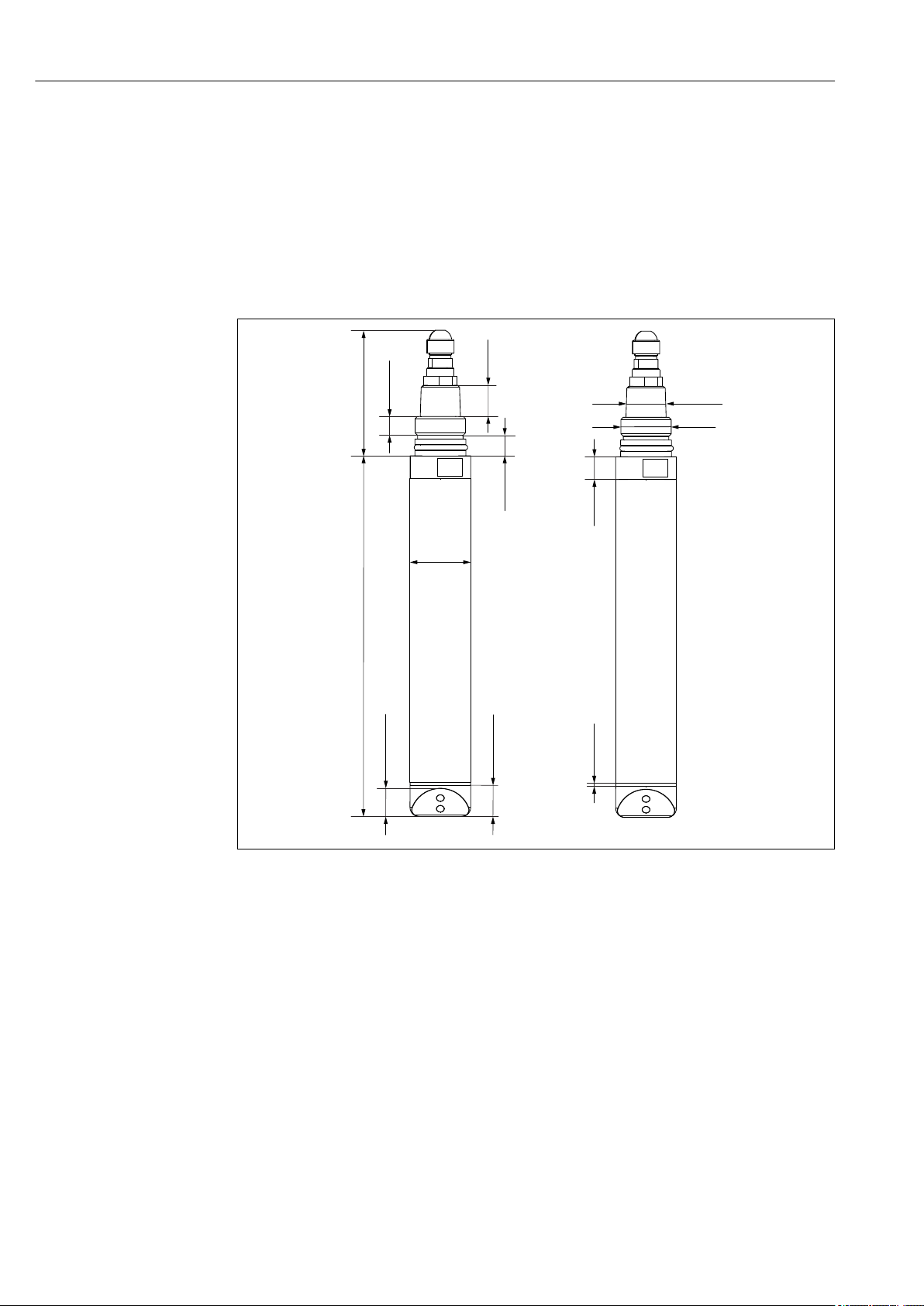
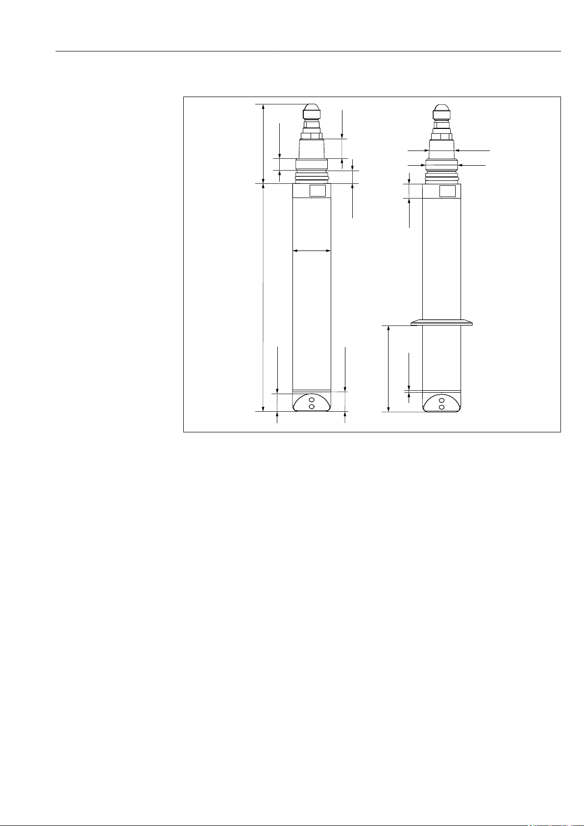
5.1.1 Dimensions
Plastic sensor
3 Dimensions of plastic sensor. Dimensions: mm (in)
10 Endress+Hauser
A0042002
Page 11
Turbimax CUS52D Installation
Ø 40
(1.57)
NPT ¾“
G1
237.5 (9.35)
82.7 (3.26)
84.5 (3.33)
2 (0.08)
20.5 (0.81)
18.5 (0.73)
12.5
(0.49)
13.5
(0.53)
20.5
(0.81)
15
(0.59)
Stainless steel sensor
4 Dimensions of stainless steel sensor and stainless steel sensor with clamp connection (right). Dimensions:
mm (in)
A0030699
Endress+Hauser 11
Page 12
Installation Turbimax CUS52D
18.5 (0.73)
82.7 (3.26)
237.5(9.35)
(1.57)
Ø 40
12.5
(0.49)
20.5
(0.81)
13.5
(0.53)
NPT ¾“
G1
15 (0.59)
2 (0.08)
20.5 (0.81)
42.5
(1.67)
22.5 (0.89)
35.5 (1.40)
13 (0.51)
A0035857
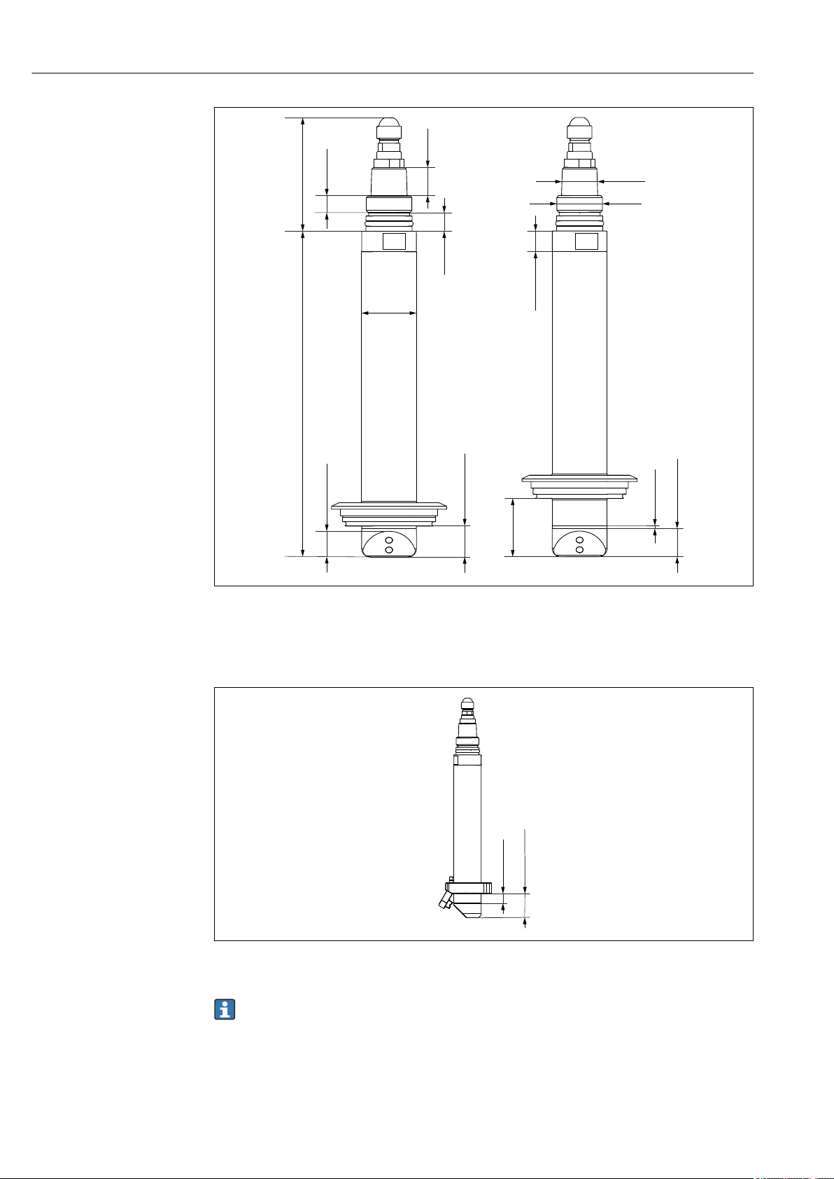
5 Dimensions of stainless steel sensor with standard Varivent connection (left) and extended shaft (right).
Dimensions: mm (in)
Compressed air cleaning
A0030691
6 Dimensions of sensor with compressed air cleaning. Dimensions: mm (in)
Compressed air cleaning accessory → 39
12 Endress+Hauser
Page 13
Turbimax CUS52D Installation
45 (1.77)
58 (2.28)
60 (2.36)
43 (1.69)
86 (3.39)
30
(1.18)
Ø 40 (1.57)
9.5 (0.37)
4
2
1
3
5
2
3
4
90°
Solid state reference
A0030821
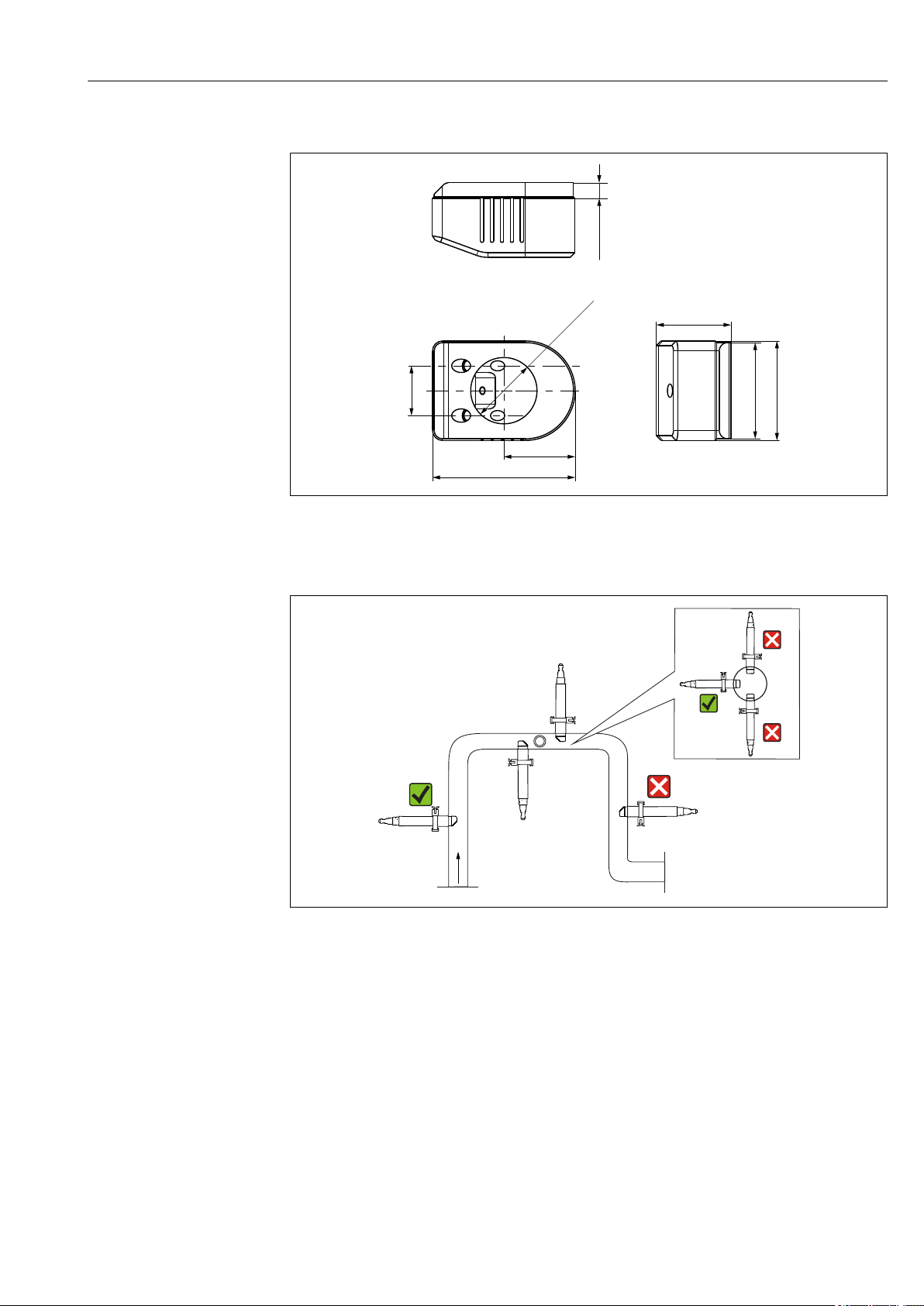
7 Solid state reference Calkit CUS52D. Dimensions: mm (in)
5.1.2 Orientation in pipes
8 Permitted and unacceptable orientations in pipes
• Install the sensor in places with consistent flow conditions.
• The best installation location is in the ascending pipe (item 1). Installation in the
horizontal pipe (item 4) is also possible.
• Do not install the sensor in places where air spaces or bubbles occur (item 3) or where
sedimentation may occur (item 2).
• Avoid installation in the down pipe (item 5).
• Avoid fittings downstream from pressure reduction stages which can lead to outgassing.
Wall effects
Backscattering on the pipe wall may result in the distortion of measured values in the case
of turbidity values < 200 FNU. Therefore a pipeline diameter of at least 100 mm (3.9 in) is
recommended for reflecting materials (e.g. stainless steel). An assembly adjustment onsite
is also recommended.
Endress+Hauser 13
A0030698
Page 14
Installation Turbimax CUS52D
6
7
8
9
10
1
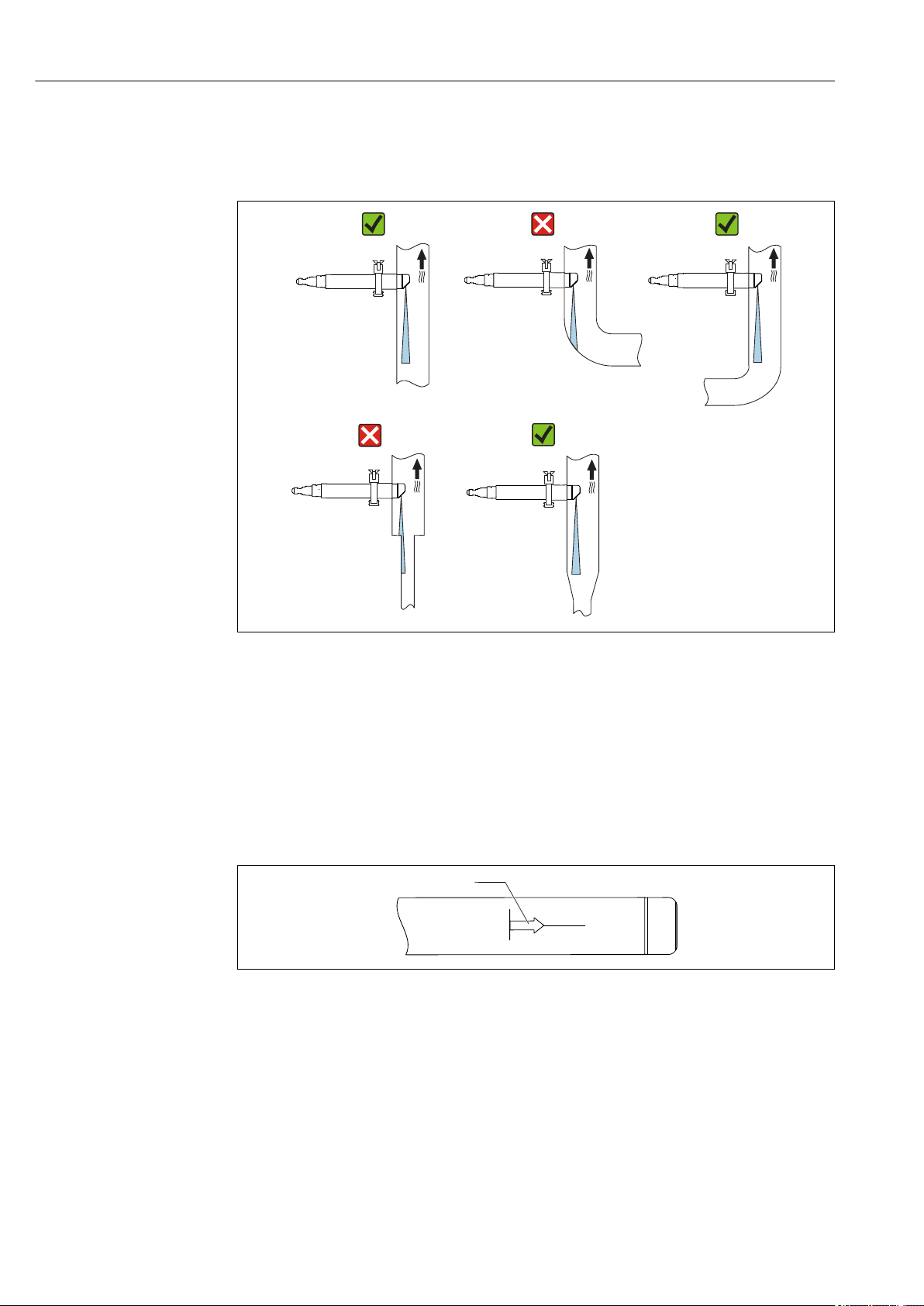
Pipes made of stainless steel with diameter >DN 300 exhibit hardly any wall effects.
Black plastic pipes with diameter > DN 60 exhibit hardly any wall effects (<0.05 FNU). For
this reason, the use of black plastic pipes is recommended.
A0030704
9 Orientations for pipes and assemblies
• Install the sensor in such a way that the light beam is not reflected → 9, 14 (item
6).
• Avoid sudden changes in cross-section (item 9). Changes in cross-section should be
gradual and located as far away as possible from the sensor (item 10).
• Do not install the sensor directly downstream from a bend (item 7). Instead position it as
far away as possible from the bend (item 8).
Installation marking
10 Installation marking for sensor alignment
1 Installation marking
A0030820
The installation marking on the sensor is aligned opposite the optical system.
Align the sensor against the flow direction.
‣
14 Endress+Hauser
Page 15
Turbimax CUS52D Installation
1
2
3
4
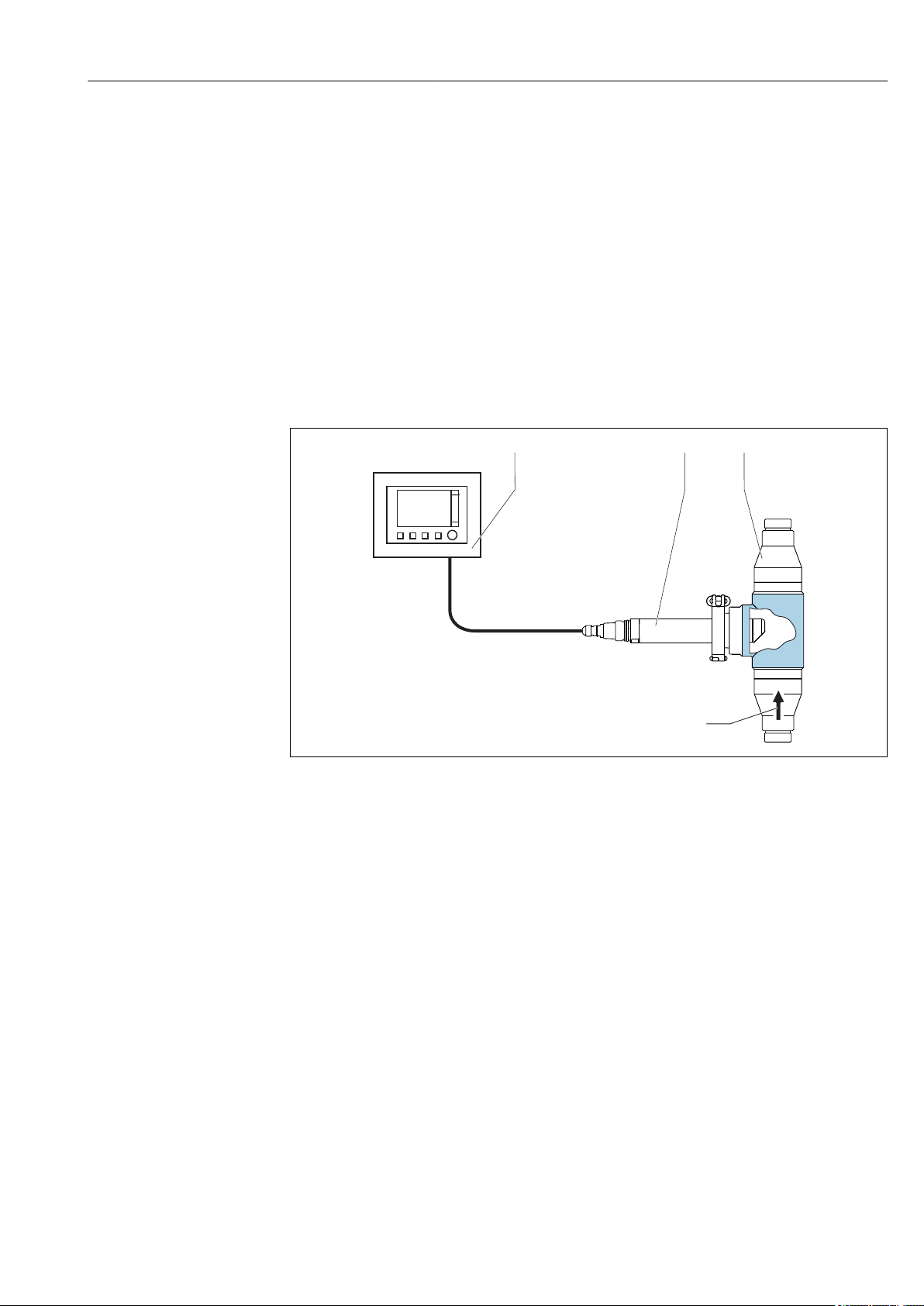
5.2 Mounting the sensor
5.2.1 Measuring system
A complete measuring system comprises:
• Turbimax CUS52D turbidity sensor
• Liquiline CM44x multi-channel transmitter
• Assembly:
• CUA252 flow assembly (only possible for stainless steel sensor) or
• CUA262 flow assembly (only possible for stainless steel sensor) or
• Flexdip CYA112 assembly and Flexdip CYH112 holder or
• Retractable assembly, e.g. Cleanfit CUA451
• Or direct installation via pipe connection (only possible for stainless steel sensor)
• Clamp 2" or
• Varivent
A0030694
11 Example of measuring system with CUA252 flow assembly, for stainless steel sensor
1 Liquiline CM44x multi-channel transmitter
2 Turbimax CUS52D turbidity sensor
3 CUA252 flow assembly
4 Direction of flow
Endress+Hauser 15
Page 16

Installation Turbimax CUS52D
1
2
3
1
4
5
2
A0030696
12 Example of measuring system with immersion assembly
1 Flexdip CYH112 holder
2 Liquiline CM44x multi-channel transmitter
3 Protective cover
4 Flexdip CYA112 assembly
5 Turbimax CUS52D turbidity sensor
This type of installation is particularly suitable for strong or turbulent flow
> 0.5 m/s (1.6 ft/s) in basins or channels.
5.2.2 Mounting options
Installing with CUA451 retractable assembly
13 Installing with CUA451 retractable assembly
The installation angle is 90°.
The arrow points in the direction of flow.
The optical windows in the sensor must be
aligned against the direction of flow.
The medium pressure may not exceed
2 bar (29 psi) for manual assembly
retraction.
A0022285
16 Endress+Hauser
Page 17

Turbimax CUS52D Installation
60 ... 64
(2.36 ... 2.52)
> 100 (3.94)
36
(1.42)
Installing with Flexdip CYA112 immersion assembly and Flexdip CYH112 holder
The installation angle is 0°.
The arrow points in the direction of flow.
A0022033
14 Installing with immersion assembly
If the sensor is being used in open basins, install the sensor in such a way that air
‣
bubbles cannot accumulate on it.
Installing with 2" clamp connection
A0022032
15 Installing with 2" clamp connection
The installation angle is 90°.
The arrow points in the direction of flow.
The optical windows in the sensor must be
aligned against the direction of flow.
A weld-in adapter is available as an accessory for
the installation → 39.
16 Pipe connection with weld-in adapter. Dimensions: mm (in)
Endress+Hauser 17
A0030819
Page 18

Installation Turbimax CUS52D
Installing with CUA252 or CUA262 flow assembly
The installation angle is 90°.
The arrow points in the direction of flow.
The optical windows in the sensor must be
aligned against the direction of flow.
A0022034
17 Installing with CUA252 flow assembly
The installation angle is 90°.
The arrow points in the direction of flow.
The optical windows in the sensor must be
aligned against the direction of flow.
A0022281
18 Installing with CUA262 flow assembly
Installing in Varivent assemblies
A0031130
19 Installing with standard Varivent connection
A0031132
20 Installing with Varivent connection with extended
shaft
The installation angle is 90°.
The arrow points in the direction of
flow.
The optical windows in the sensor
must be aligned against the direction
of flow.
18 Endress+Hauser
Page 19

Turbimax CUS52D Installation
1
2
3
4
5
6
7
8
9
10
Installation with CUA252 flow assembly and bubble trap
A0035917
21 Connection example with bubble trap and CUA252 flow assembly
1 Inlet from below
2 Shut-off valve
3 Bubble trap
4 Venting of bubble trap (included in scope of delivery)
5 Shut-off valve (throttle for increasing pressure)
6 Outlet
7 D 12 adapter with connection for vent pipe (included in scope of delivery)
8 CUA252 flow assembly
9 CUS52D turbidity sensor
10 D 12 adapter
For detailed information on installing the assembly and the bubble trap, see
BA01281C
Endress+Hauser 19
Page 20

Installation Turbimax CUS52D
1
2
3
20°
Compressed air cleaning
A0030785
22 Installation markings 1 to 3
23 Mounting position
Mount the compressed air cleaning system as follows:
1. Fit the compressed air cleaning system on the sensor (→ 23).
2. Position the securing ring for the compressed air cleaning system between
installation marks 2 and 3 (→ 22).
3. Using a 4 mm (0.16 in) Allen key, tighten the securing screw of the compressed air
cleaning system slightly so that the compressed air cleaning system can still be
rotated.
4. Turn the compressed air cleaning system so that the slit on the black ring is on
installation mark 1 (→ 22).
This way the nozzle is offset by 20° when blowing air at the optical windows.
5. Tighten the securing screw.
6. Fit the compressed air hose on the hose connection.
5.3 Post-installation check
Put the sensor into operation only if the following questions can be answered with "yes":
• Are the sensor and cable undamaged?
• Is the orientation correct?
• Has the sensor been installed in the process connection, and does not suspend freely
from the cable?
A0030786
20 Endress+Hauser
Page 21

Turbimax CUS52D Electrical connection
85 86
85
2DS
1
2
86
97 88 8798
97 88 8798
Sensor 1
Sensor 2
PK
GY
GN
YE
Sensor
85 86
85
1
2
86
97 88 8798
Sensor 1
PK
GY
GN
YE
BN
WH
Sensor
6 Electrical connection
WARNING
L
Device is live!
Incorrect connection may result in injury or death!
The electrical connection may be performed only by an electrical technician.
‣
The electrical technician must have read and understood these Operating Instructions
‣
and must follow the instructions contained therein.
Prior to commencing connection work, ensure that no voltage is present on any cable.
‣
6.1 Connecting the sensor
The following connection options are available:
• via M12 connector (version: fixed cable, M12 connector)
• via sensor cable to the plug-in terminals of a sensor input on the transmitter (version:
fixed cable, end sleeves)
A0033092
24 Sensor connection to sensor input (left) or via M12 connector (right)
Endress+Hauser 21
Page 22

Electrical connection Turbimax CUS52D
1
2
3
4
Connecting the cable shield
Cable sample (does not necessarily correspond to the original cable supplied)
25 Terminated cable
1 Outer shield (exposed)
2 Cable cores with ferrules
3 Cable sheath (insulation)
26 Inserting the cable
4 Grounding clip
27 Tightening the screw
(2 Nm (1.5 lbf ft))
The cable shield is grounded by the
grounding clip
The maximum cable length is 100 m (328.1 ft).
6.2 Ensuring the degree of protection
Only the mechanical and electrical connections which are described in these instructions
and which are necessary for the required, designated use, may be carried out on the device
delivered.
Exercise care when carrying out the work.
‣
Individual types of protection permitted for this product (impermeability (IP), electrical
safety, EMC interference immunity) can no longer be guaranteed if, for example :
• Covers are left off
• Different power units to the ones supplied are used
• Cable glands are not sufficiently tightened (must be tightened with 2 Nm (1.5 lbf ft) for
the permitted level of IP protection)
• Unsuitable cable diameters are used for the cable glands
• Modules are not fully secured
• The display is not fully secured (risk of moisture entering due to inadequate sealing)
• Loose or insufficiently tightened cables/cable ends
• Conductive cable strands are left in the device
6.3 Post-connection check
Device condition and specifications Action
Are the sensor, assembly, or cables free from damage on
the outside?
Electrical connection Action
Are the mounted cables strain-relieved and not twisted?
Is a sufficient length of the cable cores stripped, and are
the cores positioned in the terminal correctly?
Are all the screw terminals properly tightened?
22 Endress+Hauser
Are all cable entries mounted, tightened and leak-tight? In the case of lateral cable entries:
Are all cable entries installed downwards or mounted
laterally?
Perform a visual inspection.
‣
Untwist the cables.
‣
Pull gently to check they are seated correctly.
‣
Tighten the screw terminals.
‣
Point cable loops downward so that water can
‣
drip off.
Page 23

Turbimax CUS52D Commissioning
7 Commissioning
7.1 Function check
Prior to initial commissioning, ensure that:
• The sensor is correctly installed
• The electrical connection is correct.
Before commissioning, check the chemical compatibility of materials, the temperature
‣
range and the pressure range.
Endress+Hauser 23
Page 24

Operation Turbimax CUS52D
8 Operation
8.1 Adapting the measuring device to the process
conditions
8.1.1 Applications
The formazine factory calibration is used as the basis for precalibrating additional
applications and optimizing them for the different media characteristics.
Application Specified operational range
Formazine 0.000 to 1000 FNU
Kaolin 0 to 150 mg/l
PSL 0 to 125
Diatomite 0 to 550 mg/l
To adapt to a specific application, customer calibrations can be carried out with up to 6
points.
NOTICE
Multiple scattering
If the specific operational range is exceeded, the measured value displayed by the sensor
can decrease despite increasing turbidity. The indicated operational range is reduced in the
case of highly absorbing (e.g. dark) media.
In the case of highly absorbing (e.g. dark) media, determine the operational range
‣
experimentally beforehand.
8.1.2 Calibration
The sensor is precalibrated on leaving the factory. As such, it can be used in a wide range
of applications without the need for additional calibration.
The sensor offers the following options for adapting the measurement to the specific
application:
• Assembly adjustment (compensation for wall effects in pipes and assemblies)
• Calibration or adjustment (1 to 6 points)
• Entering of a factor (multiplication of measured values by a constant factor)
• Entering of an offset (addition/subtraction of a constant value to/from the measured
values)
• Duplication of factory calibration data records
24 Endress+Hauser
Page 25

Turbimax CUS52D Operation
yes
no
start measurement
measurement
correct
?
pipe or assembly
where is the
sensor installed
?
open basin
or channel
measurement
correct
?
activate reflection
compensation
no
yes
calibrate
and
adjust
end
28 Flowchart
Assembly adjustment
Both the optical design of sensor CUS52D and flow assemblies CUA252 and CUA262 are
optimized to minimize measuring errors caused by wall effects in assemblies or pipes
(measuring error in CUA252 < 0.02 FNU).
You can use the Assembly adjustment function to automatically compensate for any
remaining measuring errors caused by wall effects. The functionality is based on formazine
measurements and may thus require a calibration downstream in order to adapt the
measurement to the corresponding application or medium.
Adjustment Description
PE 100 Adjustment to flow assembly CUA252 (material: polyethylene)
1.4404 (AISI 316 L) Adjustment to flow assembly CUA262 (material: stainless steel 1.4404)
Customized, standard Adjustment to any pipe/assembly
Customized, advanced Adjustment only recommended for Endress+Hauser service personnel
A0030787-EN
In order to be able to use the "Offset", "Factor" or "Assembly adjustment" functions, a
new data record must first be generated by means of a 1 to 6-point calibration or by
duplication of a factory data record.
Endress+Hauser 25
Page 26

Operation Turbimax CUS52D
• PE100 and 1.4404/316L
All of the parameters are assigned default values in the firmware and cannot be
changed.
• Standard customization
It is possible to select the material, surface (matte/shiny) and the internal diameter of
the assembly in which the sensor is installed.
• Customized advanced
For special adjustments, the following table provides recommendations. Alternatively,
adjustments can be performed by the manufacturer's service department.
Assembly/pipe built-in adapter Zero adjustment Upper Limit Adjustment characteristic
1)
CUA250
1)
CYA251
VARIVENT N DN 65 1.28 500 6
VARIVENT N DN 80 0.75 500 6
VARIVENT N DN 100 0.35 500 6
VARIVENT N DN 125 0.20 500 6
1) Sensor adapter required to fit CUS52D in this assembly,
0.14 33 1.001
0.075 25 1.5
Application selection
During initial commissioning or calibration at the CM44x, select the appropriate
‣
application for your field of application.
Application Field of application Unit
Formazine Drinking water, process water FNU; NTU; TE/F; EBC; ASBC
Kaolin Drinking water, filterable matter, industrial water mg/l; g/l; ppm
PSL The calibration standard commonly used in Japan for drinking
water turbidity
Diatomite Mineral-based solids (sand) mg/l; g/l; ppm
(dough)
1 to 6 points can be calibrated for all applications.
In addition to the factory calibrations, which cannot be changed, the sensor contains 6
additional data records for storing process calibrations or for adjusting them to the
relevant measuring point (application).
1-point and multipoint calibration
1. Before a calibration, rinse the system until all air pockets and fouling have been
removed.
2. In the calibration table, edit the actual values as well as the set points (right and left
columns).
3. Add additional pairs of calibration values, even without measurement in a medium.
When factory calibration data records are duplicated, the value pair 1000/1000 is
automatically generated to map the factory data record 1:1 to the duplicated record.
If a single-point or multipoint calibration is performed following duplication, delete the
‣
value pair (1000/1000) in the calibration table
Lines interpolate between the calibration points.
26 Endress+Hauser
Page 27

Turbimax CUS52D Operation
1 2 3 4 5 6 7 8
1
2
3
4
5
6
x
y
a
b
1-point calibration
The measured error between the measured value of the device and the laboratory
measured value is too large. This is corrected by a 1-point calibration.
A0039320
29 Principle of a 1-point calibration
x Measured value
y Target sample value
a Factory calibration
b Application calibration
1. Select data record.
2. Set the calibration point in the medium and enter the target sample value (laboratory
value).
2-point calibration
Measured value deviations are to be compensated for at 2 different points in an
application (e.g. the maximum and minimum value of the application). This aims to ensure
a maximum level of accuracy between these two extreme values.
Endress+Hauser 27
Page 28

Operation Turbimax CUS52D
1 2 3 4 5 6 7 8
1
2
3
4
5
6
x
y
a
b
1 2 3 4 5 6 7 8
1
2
3
4
5
6
x
y
a
b
A0039325
30 Principle of a 2-point calibration
x Measured value
y Target sample value
a Factory calibration
b Application calibration
1. Select a data record.
2. Set 2 different calibration points in the medium and enter the corresponding set
points.
A linear extrapolation is performed outside the calibrated operational range (gray
line).
The calibration curve must be monotonically increasing.
3-point calibration
28 Endress+Hauser
31 Principle of multipoint calibration (3 points)
x Measured value
y Target sample value
a Factory calibration
b Application calibration
A0039322
Page 29

Turbimax CUS52D Operation
100 200 300 400 500 600 700 800 1000900
FNU
200
400
600
800
1000
FNU
Factory calibration
Application calibration
1. Select data record.
2. Set 3 different calibration points in the medium and specify the corresponding set
points.
A linear extrapolation is performed outside the calibrated operational range (gray
line).
The calibration curve must be monotonically increasing.
Calibration example for filter monitoring
Application example:
If a threshold is exceeded, the measured value is set to a maximum regardless of the actual
turbidity.
A0030814-EN
32 Example for filter monitoring
The following table shows the values in the example (→ 32):
Measured value Target sample value
0 0
100 100
101 1000
1000 1001
Stability criterion
During calibration, the measured values provided by the sensor are checked to ensure they
are constant. The maximum deviations that may occur in measured values during a
calibration are defined in the stability criterion.
The specifications comprise the following:
• The maximum permitted deviation in temperature measurement
• The maximum permitted deviation in measured value as a %
• The minimum time frame in which these values must be maintained
The calibration resumes as soon as the stability criteria for signal values and temperature
have been reached. If these criteria are not met in the maximum time frame of 5 minutes,
no calibration is performed - a warning is issued.
Endress+Hauser 29
Page 30

Operation Turbimax CUS52D
1 2 3 4 5 6 7 8
1
2
3
4
5
6
x
y
f = 1.1
a
b
The stability criteria are used to monitor the quality of the individual calibration points in
the course of the calibration process. The aim is to achieve the highest possible calibration
quality in the shortest possible time frame while taking external conditions into account.
For calibrations in the field in adverse weather and environmental conditions, the
measured value windows selected can be suitably large and the time frame selected
can be suitably short.
Factor
With the "Factor" function, the measured values are multiplied by a constant factor. The
functionality corresponds to that of a 1-point calibration.
Example:
This type of adjustment can be selected if the measured values are compared to the
laboratory values over a longer period of time and all values are too low by a constant
factor, e.g. 10%, in relation to the laboratory value (target sample value).
In the example, the adjustment is made by entering the factor 1.1.
A0039329
33 Principle of factor calibration
x Measured value
y Target sample value
a Factory calibration
b Factor calibration
Offset
With the "Offset" function, the measured values are offset by a constant amount (added or
subtracted).
30 Endress+Hauser
Page 31

Turbimax CUS52D Operation
1 2 3 4 5 6 7 8
1
2
3
4
5
6
x
y
a
b
A0039330
34 Principle of an offset
x Measured value
y Target sample value
a Factory calibration
b Offset calibration
8.1.3 Cyclic cleaning
For cyclic cleaning in open basins or channels, compressed air is the most suitable option.
The cleaning unit is either supplied or can be retrofitted, and is attached to the sensor
head. The following settings are recommended for the cleaning unit:
Type of fouling Cleaning interval Cleaning duration
Severe fouling with rapid buildup of deposits 5 minutes 10 seconds
Low risk of fouling 10 minutes 10 seconds
The CYR52 ultrasonic cleaning unit is suitable for cyclic cleaning in pipes or assemblies.
The cleaning unit (which can also be retrofitted) can be mounted on the CUA252, CUA262
flow assemblies or on any customer pipes.
The following cleaning settings are recommended to prevent the ultrasonic transducer
from overheating:
• Cleaning duration: maximum 5 seconds
• Cleaning interval: minimum 5 minutes
8.1.4 Signal filter
The sensor is fitted with an internal signal filter function in order to adapt the
measurement flexibly to different measuring requirements. Turbidity measurements based
on the principle of scattered light may have a low signal-to-noise ratio. In addition,
disturbances can occur as a result of air bubbles or fouling, for example.
However, a high level of damping affects the sensitivity of the measured value required in
applications.
Measured value filter
Endress+Hauser 31
Page 32

Operation Turbimax CUS52D
The following filter settings are available:
Measured value filter Description
Weak Low filtering, high sensitivity, fast response to changes (2 seconds)
Normal (default) Medium filtering, 10-second response time
Strong Strong filtering, low sensitivity, slow response to changes (25 seconds)
Specialist This menu is designed for the Endress+Hauser Service Department.
8.1.5 Solid state reference
The solid state reference can be used to check the functional integrity of the sensor.
During factory calibration, each Calkit solid state reference is matched specifically to a
special CUS52D sensor and can be used only with this sensor. Therefore, the Calkit solid
state reference and the CUS52D sensor are permanently assigned (married) to one
another.
The following Calkit solid state references are available:
• 5 FNU (NTU)
• 20 FNU (NTU)
• 50 FNU (NTU)
The reference value indicated on the Calkit solid state reference is reproduced with an
accuracy of ± 10% when the sensor is operating correctly.
The CUY52 solid state reference with approx. 4.0 FNU/NTU is used to check the function
of any CUS52D sensors. The standard is not assigned to a specific sensor and delivers
measured values in the range of 4.0 FNU ± 1.5 FNU/NTU with all CUS52D sensors.
A0035755
35 Solid state reference
32 Endress+Hauser
Page 33

Turbimax CUS52D Operation
A B
C
D
Function check with solid state reference
A0030842
36 Fitting the solid state reference on the sensor
Preparation:
1. Clean the sensor → 36.
2. Fix the sensor in place (e.g. with a laboratory stand).
3. With the solid state reference turned slightly (→ 36, B), fit it gently on the sensor
(C).
4. Slide the solid state reference into the final position (D).
Function check:
1. Enable the factory calibration on the transmitter.
2. Read the measured value at the transmitter (depending on the signal filter settings, it
can take 2 to 25 seconds until the correct measured value appears).
3. Compare the measured value with the reference value on the solid state reference.
The sensor is working correctly if the value deviation is within the imprinted
tolerance.
If you activate a calibration data record, other measured values will result. Therefore,
always select the factory calibration (formazine) when checking the function with the
calibration kit.
Calibration vessel
The CUY52 calibration vessel allows the sensors to be validated quickly and reliably. This
makes it easier to adapt to the actual measuring point by creating basic conditions that are
reproducible (e.g. vessels with minimal backscattering, shade from interfering light
sources etc.). There are two different types of calibration vessel into which the calibration
solution (e.g. formazine) can be transferred.
Endress+Hauser 33
Page 34

Operation Turbimax CUS52D
92
(3.62)
150 (5.91)
95°
293 (11.54)
42
80 (3.15)
95°
127 (5.00)
A0035756
37 Large calibration vessel (top) and small calibration vessel (bottom). Dimensions: mm (in)
For detailed information on calibration tools, see BA01309C
34 Endress+Hauser
Page 35

Turbimax CUS52D Diagnostics and troubleshooting
9 Diagnostics and troubleshooting
9.1 General troubleshooting
When troubleshooting, the entire measuring point must be taken into account:
• Transmitter
• Electrical connections and cables
• Assembly
• Sensor
The possible causes of error in the following table relate primarily to the sensor.
Problem Testing Solution
No display, no sensor reaction • Power supplied to transmitter?
• Sensor connected correctly?
• Buildup on optical windows?
Display value too high or too low • Buildup on optical windows?
• Sensor calibrated?
Display value fluctuating greatly Is the mounting location correct? • Select a different mounting location
• Connect mains voltage
• Connect sensor correctly
• Clean sensor
• Cleaning
• Calibration
• Adjust the measured value filter
Pay attention to the troubleshooting information in the Operating Instructions for the
transmitter. Check the transmitter if necessary.
Endress+Hauser 35
Page 36

Maintenance Turbimax CUS52D
10 Maintenance
CAUTION
L
Acid or medium
Risk of injury, damage to clothing and the system!
Switch off the cleaning unit before removing the sensor from the medium.
‣
Wear protective goggles and safety gloves.
‣
Clean away splashes on clothes and other objects.
‣
You must perform maintenance tasks at regular intervals.
‣
We recommend setting the maintenance times in advance in an operations journal or log.
The maintenance cycle primarily depends on the following:
• The system
• The installation conditions
• The medium in which measurement takes place
10.1 Maintenance tasks
10.1.1 Cleaning the sensor
Sensor fouling can affect the measurement results and even cause a malfunction.
The sensor must be cleaned regularly to ensure reliable measurement results. The
frequency and intensity of the cleaning process depend on the medium.
Clean the sensor:
• As specified in the maintenance schedule
• Before every calibration
• Before returning it for repairs
Type of fouling Cleaning measure
Lime deposits
Dirt particles on the optics
After cleaning:
Rinse the sensor thoroughly with water.
‣
Immerse the sensor in 1 to 5% hydrochloric acid (for several minutes).
‣
Clean the optics with a cleaning cloth.
‣
36 Endress+Hauser
Page 37

Turbimax CUS52D Repair
11 Repair
11.1 General information
Only use spare parts from Endress + Hauser to guarantee the safe and stable
‣
functioning of the device.
Detailed information on the spare parts is available at:
www.endress.com/device-viewer
11.2 Spare parts
For more detailed information on spare parts kits, please refer to the "Spare Part Finding
Tool" on the Internet:
www.products.endress.com/spareparts_consumables
11.3 Return
The product must be returned if repairs or a factory calibration are required, or if the
wrong product was ordered or delivered. As an ISO-certified company and also due to legal
regulations, Endress+Hauser is obliged to follow certain procedures when handling any
returned products that have been in contact with medium.
To ensure the swift, safe and professional return of the device:
Refer to the website www.endress.com/support/return-material for information on the
‣
procedure and conditions for returning devices.
11.4 Disposal
The device contains electronic components. The product must be disposed of as electronic
waste.
Observe the local regulations.
‣
Endress+Hauser 37
Page 38

Accessories Turbimax CUS52D
12 Accessories
The following are the most important accessories available at the time this documentation
was issued.
For accessories not listed here, please contact your Service or Sales Center.
‣
12.1 Assemblies
FlowFit CUA120
• Flange adapter for mounting turbidity sensors
• Product Configurator on the product page: www.endress.com/cua120
Technical Information TI096C
Flowfit CUA252
• Flow assembly
• Product Configurator on the product page: www.endress.com/cua252
Technical Information TI01139C
Flowfit CUA262
• Weld-in flow assembly
• Product Configurator on the product page: www.endress.com/cua262
Technical Information TI01152C
Flexdip CYA112
• Immersion assembly for water and wastewater
• Modular assembly system for sensors in open basins, channels and tanks
• Material: PVC or stainless steel
• Product Configurator on the product page: www.endress.com/cya112
Technical Information TI00432C
Cleanfit CUA451
• Manual retractable assembly made of stainless steel with ball valve shut-off for turbidity
sensors
• Product Configurator on the product page: www.endress.com/cua451
Technical Information TI00369C
Flowfit CYA251
• Connection: See product structure
• Material: PVC-U
• Product Configurator on the product page: www.endress.com/cya251
Technical Information TI00495C
Flowfit CUA250
• Flow assembly for water and wastewater applications
• Product Configurator on the product page: www.endress.com/cua250
Technical Information TI00096C
Built-in adapter
• For installing CUS52D in CUA250 or CYA251 assembly
• Order number: 71248647
38 Endress+Hauser
Page 39

Turbimax CUS52D Accessories
Ø 53 (2.09)
30 (1.18)
36 (1.42)
Ø 64 (2.52)
60 ... 64
(2.36 ... 2.52)
> 100 (3.94)
36
(1.42)
12.2 Holder
Flexdip CYH112
• Modular holder system for sensors and assemblies in open basins, channels and tanks
• For Flexdip CYA112 water and wastewater assemblies
• Can be affixed anywhere: on the ground, on the coping stone, on the wall or directly
onto railings.
• Stainless steel version
• Product Configurator on the product page: www.endress.com/cyh112
Technical Information TI00430C
12.3 Mounting material
Weld-in adapter for clamp connection DN 50
• Material: 1.4404 (AISI 316 L)
• Wall thickness 1.5 mm (0.06 in)
• Order number: 71242201
A0030841
38 Weld-in adapter. Dimensions: mm (in)
A0030819
39 Pipe connection with weld-in adapter. Dimensions: mm (in)
12.4 Compressed air cleaning
Compressed air cleaning for stainless steel sensors
• Pressure 1.5 to 2 bar (21.8 to 29 psi)
• Connection: 6 mm (0.24 in) or 8 mm (0.31 in)
• Materials: POM black, stainless steel
• Order number: 71242026
Endress+Hauser 39
Page 40

Accessories Turbimax CUS52D
76.4 (3.01)
65.7 (2.59)
Ø 40 (1.57
)
60 (2.36)
8.75
(0.34)
25
(0.98)
18 (0.71)
21.7
(0.85)
x
A0030837
40 Compressed air cleaning for stainless steel sensors. Dimensions: mm (in)
X 6 mm (0.2 in) hose barb
Compressor
• For compressed air cleaning
• 230 V AC, order number: 71072583
• 115 V AC, order number: 71194623
12.5 Ultrasonic cleaning
Ultrasonic cleaning system CYR52
• For attachment to assemblies and pipes
• Product Configurator on the product page: www.endress.com/cyr52
Technical Information TI01153C
12.6 Bubble trap
Bubble trap
• For sensor CUS52D
• Process pressure: up to 3 bar (43.5 psi)
• Process temperature: 0 to 50 °C (32 to 122 °F)
• D 12 adapter with connection for degassing line (upper connection on the CUA252) is
included in the scope of delivery.
• Orifice plates for the following volume flows:
• < 60 l/h (15.8 gal/h)
• 60 to 100 l/h (15.8 to 26.4 gal/h)
• 100 l/h (26.4 gal/h)
• The degassing line is fitted with a PVC hose, backpressure hose valve and luer lock
adapter.
• Order number, suitable for CUA252 assembly: 71242170
• Order number, suitable for assembly S of CUS31: 71247364
40 Endress+Hauser
Page 41

Turbimax CUS52D Accessories
254 (10.0)
12 (0.5)
12 (0.5)
1
2
3
A0035757
41 Bubble trap. Dimensions: mm (in)
1 Inlet for medium (without hose system)
2 Outlet for bubbles (hose system is included in scope of delivery)
3 Outlet for medium (without hose system)
12.7 Solid state reference
CUY52-AA+560
• Calibration tool for CUS52D turbidity sensor
• Easy and reliable validation and calibration of CUS52D turbidity sensors.
• Product Configurator on the product page: www.endress.com/cuy52
Technical Information TI01154C
12.8 Calibration vessel
CUY52-AA+640
• Calibration vessel for CUS52D turbidity sensor
• Easy and reliable validation and calibration of CUS52D turbidity sensors.
• Product Configurator on the product page: www.endress.com/cuy52
Technical Information TI01154C
Endress+Hauser 41
Page 42

Technical data Turbimax CUS52D
13 Technical data
13.1 Input
Measured variables • Turbidity
• Temperature
• Solids content
Measuring range
Reference operating conditions
Maximum measured error
CUS52D Application
Turbidity 0.000 to 4000 FNU
Display range up to 9999 FNU
Solids 0 to 600 mg/l
Display range up to 3 g/l
0 to 2 200 mg/l
Display range up to 10 g/l
Temperature –20 to 85 °C (–4 to 185 °F)
Formazine
Kaolin
Diatomite
Factory calibration
The sensor has been calibrated in the factory for "formazine" applications.
Basis: internal 20 point characteristic curve
13.2 Performance characteristics
20 °C (68 °F), 1013 hPa (15 psi)
Turbidity 2 % of the measured value or 0.1 FNU (the greater value applies in each case).
Reference: measured value in recommended operational range, factory
calibration
Solids < 5% of measured value or 1 % of the end of measuring range (the greater
value applies in each case). Applies for sensors that are calibrated to the
particular measuring range under analysis.
The measured error encompasses all inaccuracies of the measuring chain (sensor and
transmitter). However, it does not include the inaccuracy of the reference material
used for calibration.
For solids, the achievable measured errors depend very much on the media that are
actually present and may differ from the specified values. Extremely inhomogeneous
media cause the measured value to fluctuate and increase the measured error.
Repeatability < 0.5 % of the measured value
Long-term reliability Drift
Working on the basis of electronic controls, the sensor is largely free of drifts.
42 Endress+Hauser
Page 43

Turbimax CUS52D Technical data
Response time > 1 second, adjustable
Detection limit Detection limit in accordance with ISO 15839 in ultrapure water:
Application Measuring range Detection limit
Formazine 0 to 10 FNU (ISO 15839) 0.0015 FNU
13.3 Environment
Ambient temperature range
Storage temperature –20 to 70 °C (–4 to 158 °F)
Degree of protection IP 68 (1.8 m (5.91 ft) water column over 20 days, 1 mol/l KCl)
Electromagnetic compatibility (EMC)
–20 to 60 °C (–4 to 140 °F)
Interference emission and interference immunity as per
• EN 61326-1:2013
• EN 61326-2-3:2013
• NAMUR NE21: 2012
13.4 Process
Process temperature range Stainless steel sensor
–20 to 85 °C (–4 to 185 °F)
Plastic sensor
–20 to 60 °C (–4 to 140 °F)
Under high temperatures combined with extremely high or low pH values and chemical
boundary conditions, e.g. during CIP cleaning processes, the sensor has limited long-term
stability.
To avoid damage to the sensor, only use the sensor in combination with a retractable
assembly in CIP cleaning processes. The retractable assembly allows the sensor to be
removed from the process during cleaning.
Process pressure range Stainless steel sensor
0.5 to 10 bar (7.3 to 145 psi) (abs.)
Plastic sensor
0.5 to 6 bar (7.3 to 87 psi)
Flow limit Minimum flow
No minimum flow required.
For solids which have a tendency to form deposits, ensure that sufficient mixing is
performed.
Endress+Hauser 43
Page 44

Technical data Turbimax CUS52D
13.5 Mechanical construction
Dimensions → Section "Installation"
Weight Plastic sensor
Plastic sensor: 0.72 kg (1.58 lb)
The specifications apply to the sensor with a 7 m (22.9 ft) cable.
Stainless steel sensor
With clamp 1.54 kg (3.39 lb)
Without clamp 1.48 kg (3.26 lb)
With Varivent connection, standard 1.84 kg (4.07 lb)
With Varivent connection, extended shaft 1.83 kg (4.04 lb)
The specifications apply to the sensor with a 7 m (22.9 ft) cable.
Materials
Sensor head: PEEK GF30 Stainless steel 1.4404 (AISI 316 L)
Sensor housing: PPS GF40 Stainless steel 1.4404 (AISI 316 L)
O-rings: EPDM EPDM
Optical windows Sapphire Sapphire
Plastic sensor Stainless steel sensor
Process connections Plastic and stainless steel sensor
G1 and NPT ¾'
Stainless steel sensor
• Clamp 2" (depending on sensor version)/DIN 32676
• Varivent N DN 65 - 125 standard immersion depth 22.5 mm
• Varivent N DN 65 - 125 immersion depth 42.5 mm
44 Endress+Hauser
Page 45

Turbimax CUS52D Index
Index
0 … 9
1-point calibration .......................... 27
2-point calibration .......................... 27
3-point calibration .......................... 28
A
Accessories ................................ 38
Applications ............................... 26
Approvals .................................. 9
Marine ..................................9
Assembly adjustment ........................ 25
B
Bubble trap ................................ 19
C
Calibration ................................ 24
Calibration vessel ........................... 33
Certificates ................................. 9
Cleaning ............................... 31, 36
Compressed air cleaning ...................... 20
Cyclic cleaning ..............................31
D
Designated use .............................. 5
Diagnostics ................................ 35
Dimensions ................................10
Disposal .................................. 37
E
Electrical connection ......................... 21
Environment ...............................43
O
Offset .................................... 30
P
Performance characteristics ....................42
Post-connection check ........................22
Post-installation check ....................... 20
Process ................................... 43
Product description ........................... 7
Product design .............................. 7
Product identification ......................... 8
R
Repair ....................................37
Return ................................... 37
S
Safety instructions ............................5
Scope of delivery ............................. 9
Sensor structure ............................. 7
Signal filter ................................ 31
Solid state reference ......................... 32
Spare parts kit ..............................37
Stability criterion ............................29
Symbols ................................... 4
T
Technical data ..............................42
Troubleshooting ............................ 35
U
Use .......................................5
F
Factor .................................... 30
Filter monitoring ............................29
Function
Factor ................................. 30
Offset ................................. 30
Function check ............................. 23
I
Incoming acceptance .......................... 8
Input .....................................42
Installation ............................. 10, 15
M
Maintenance ...............................36
Marine .................................... 9
Measuring principle ...........................7
Measuring system ........................... 15
Mechanical construction ...................... 44
Mounting options ........................... 16
N
Nameplate ................................. 8
W
Warnings .................................. 4
Wiring ................................... 21
Endress+Hauser 45
Page 46

Page 47

Page 48

*71473306*
71473306
www.addresses.endress.com
 Loading...