

Page 1
TI01136C/07/EN/05.20
71473307
2020-03-16
Products
Solutions Services
Technical Information
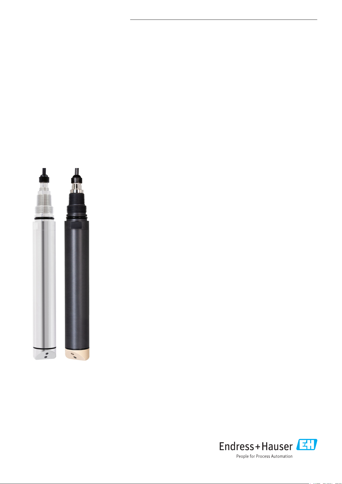
Turbimax CUS52D
Turbidity sensor
Application
Turbimax CUS52D is a sensor for measuring turbidity and low solids content in
drinking water and process water applications.
• Turbidity measurement at all stages of the water treatment process
• Final turbidity measurement in outlet of waterworks
• Turbidity measurement in inlet of waterworks
• Turbidity measurement for filter monitoring and filter backwashing
• Turbidity measurement in drinking water networks
• Turbidity measurement in saline media (plastic sensor only)
Your benefits
• Turbidity measurement in accordance with ISO 7027
• The hygienic design with the 2" clamp means it can be mounted directly in pipes
and fits into CUA252 (PE 100) and CUA262 (stainless steel) flow assemblies
• Immersion version can be installed in open channels and basins
• Can be used at high temperatures and high pressures
• Standardized communication (Memosens technology) enables "plug and play"
• Intelligent sensor - all characteristics and calibration values are stored in the
sensor
• Customer calibrations with 1 to 6 points can be performed in the lab or at place of
installation
• Completely safe, as the optical source requires little power to operate
Page 2

Table of contents
Turbimax CUS52D
Function and system design ................... 3
Measuring principle ............................ 3
Measuring system ............................. 4
Communication and data processing ................. 6
Dependability ................................ 7
Input ..................................... 7
Measured variable ............................. 7
Measuring range .............................. 7
Power supply .............................. 7
Electrical connection ........................... 7
Performance characteristics ................... 9
Reference operating conditions .................... 9
Maximum measured error ....................... 9
Repeatability ................................ 9
Long-term reliability ........................... 9
Response time ............................... 9
Detection limit ............................... 9
Installation ................................ 9
Orientation ................................. 9
Environment .............................. 13
Ambient temperature range ..................... 13
Storage temperature .......................... 13
Degree of protection .......................... 13
Electromagnetic compatibility (EMC) ............... 13
Mounting material ........................... 19
Compressed air cleaning ........................ 20
Ultrasonic cleaning ........................... 20
Bubble trap ................................ 21
Solid state reference .......................... 21
Calibration vessel ............................ 21
Process .................................. 13
Process temperature range ...................... 13
Process pressure range ......................... 13
Flow limit ................................. 13
Mechanical construction .................... 14
Dimensions ................................ 14
Weight ................................... 17
Materials .................................. 17
Process connections ........................... 17
Certificates and approvals ................... 18
mark ................................... 18
ISO 7027 .................................. 18
EAC ..................................... 18
Marine approvals ............................ 18
Ordering information ....................... 18
Scope of delivery ............................. 18
Product page ............................... 18
Product Configurator .......................... 18
Accessories ............................... 18
Assemblies ................................. 18
Holder .................................... 19
2 Endress+Hauser
Page 3
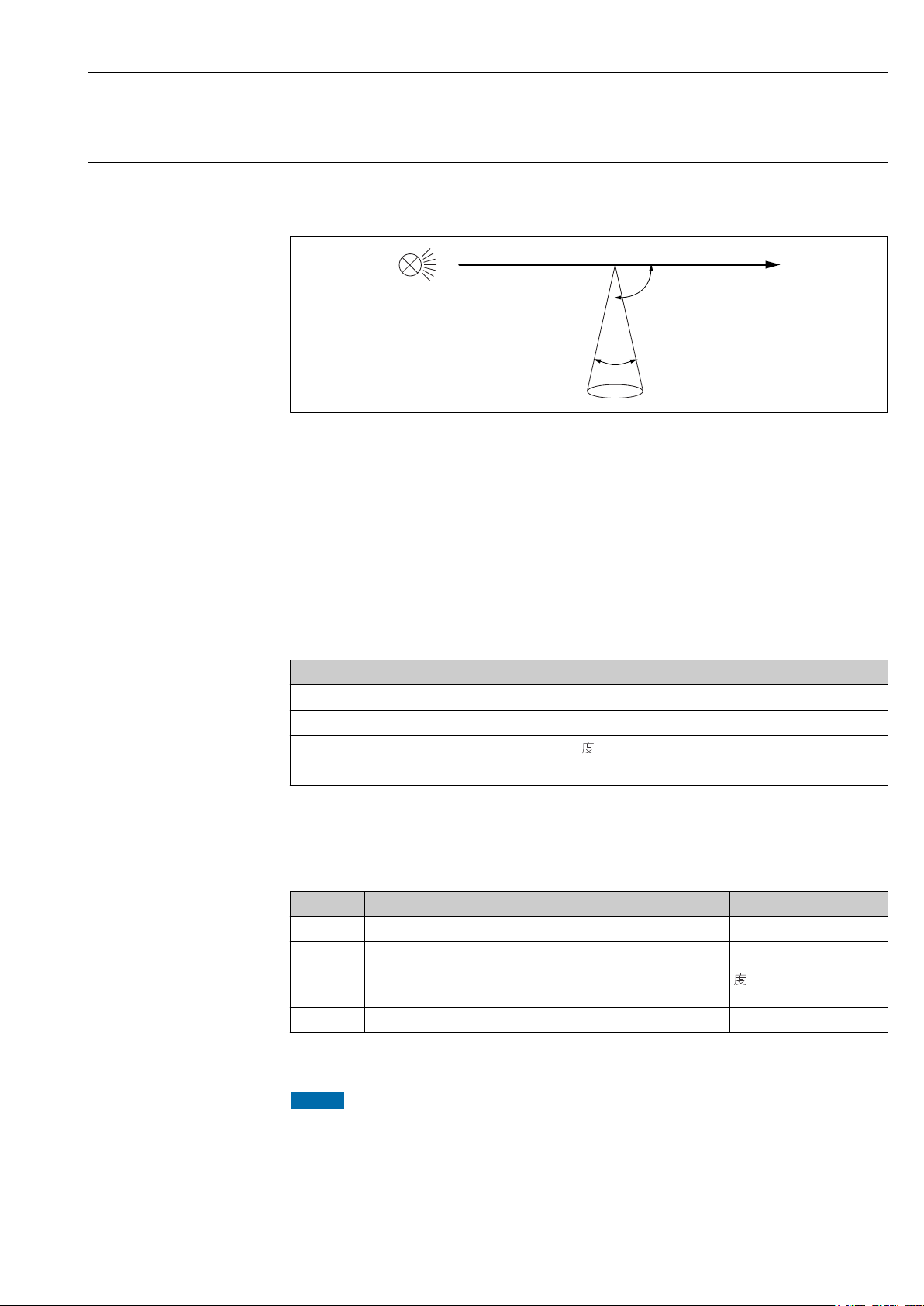
Turbimax CUS52D
90° ± 2.5°
20° - 30°
Function and system design
Measuring principle
The sensor works using the 90° light scattering principle in accordance with ISO 7027 and meets all
the requirements of this standard (no divergence and a maximum convergence of 1.5°). The ISO
7027 standard is obligatory for turbidity measurements in the drinking water sector.
A0030701
1 Measurement in accordance with ISO 7027
Measurement is done using a wavelength of 860 nm.
Sensor monitoring
The optical signals are continuously monitored and analyzed for plausibility. If inconsistencies occur,
an error message is output via the transmitter. The function is disabled by default.
Applications
The formazine factory calibration is used as the basis for precalibrating additional applications and
optimizing them for the different media characteristics.
Application Specified operational range
Formazine 0.000 to 1000 FNU
Kaolin 0 to 150 mg/l
PSL 0 to 125
Diatomite 0 to 550 mg/l
To adapt to a specific application, customer calibrations can be carried out with up to 6 points.
During initial commissioning or calibration at the CM44x, select the appropriate application for
‣
your field of application.
Application Field of application Unit
Formazine Drinking water, process water FNU; NTU; TE/F; EBC; ASBC
Kaolin Drinking water, filterable matter, industrial water mg/l; g/l; ppm
PSL The calibration standard commonly used in Japan for drinking
water turbidity
Diatomite Mineral-based solids (sand) mg/l; g/l; ppm
(dough)
1 to 6 points can be calibrated for all applications.
NOTICE
Multiple scattering
If the specific operational range is exceeded, the measured value displayed by the sensor can
decrease despite increasing turbidity. The indicated operational range is reduced in the case of highly
absorbing (e.g. dark) media.
In the case of highly absorbing (e.g. dark) media, determine the operational range
‣
experimentally beforehand.
Endress+Hauser 3
Page 4
Turbimax CUS52D
1
2
3
4
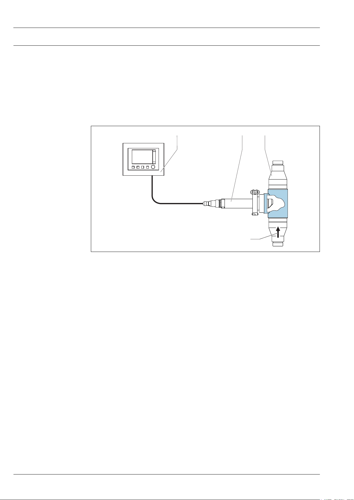
Measuring system
A complete measuring system comprises:
• Turbimax CUS52D turbidity sensor
• Liquiline CM44x multi-channel transmitter
• Assembly:
• CUA252 flow assembly (only possible for stainless steel sensor) or
• CUA262 flow assembly (only possible for stainless steel sensor) or
• Flexdip CYA112 assembly and Flexdip CYH112 holder or
• Retractable assembly, e.g. Cleanfit CUA451
• Or direct installation via pipe connection (only possible for stainless steel sensor)
• Clamp 2" or
• Varivent
A0030694
2 Example of measuring system with CUA252 flow assembly, for stainless steel sensor
1 Liquiline CM44x multi-channel transmitter
2 Turbimax CUS52D turbidity sensor
3 CUA252 flow assembly
4 Direction of flow
4 Endress+Hauser
Page 5
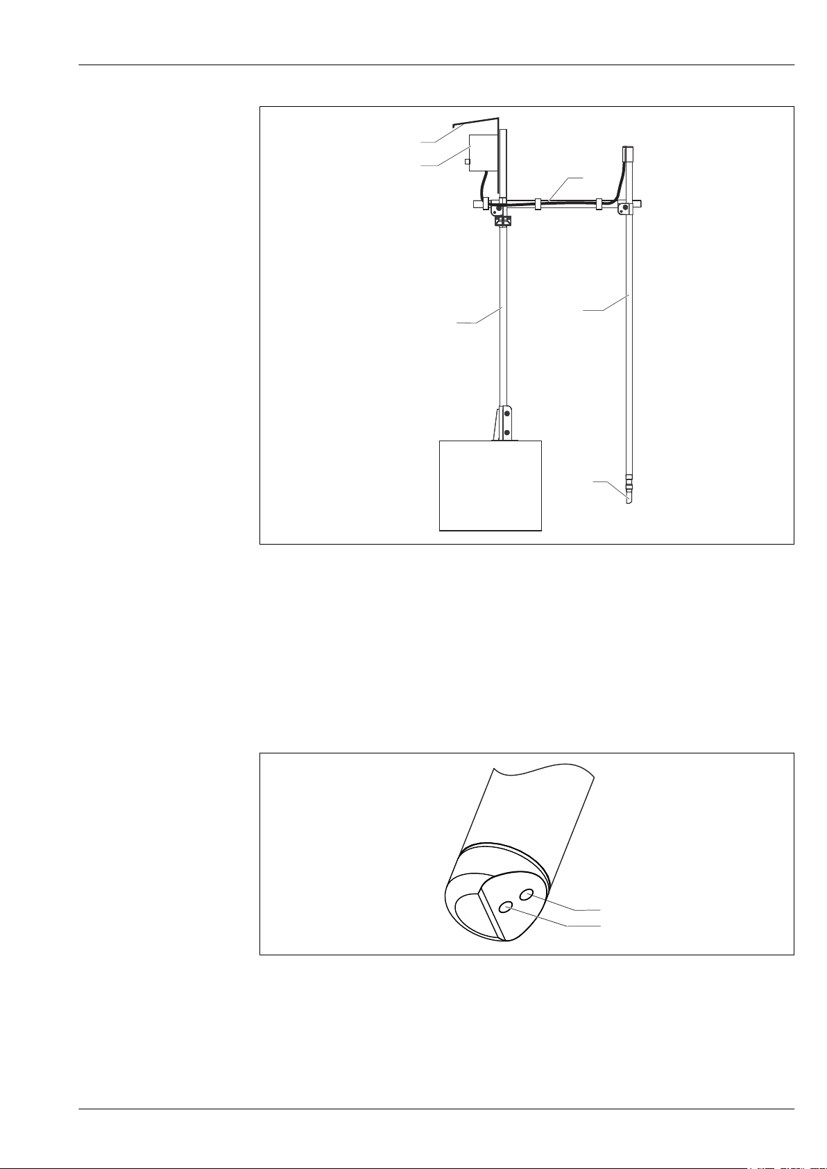
Turbimax CUS52D
1
2
3
1
4
5
1
2
A0030696
3 Example of measuring system with immersion assembly
1 Flexdip CYH112 holder
2 Liquiline CM44x multi-channel transmitter
3 Protective cover
4 Flexdip CYA112 assembly
5 Turbimax CUS52D turbidity sensor
This type of installation is particularly suitable for strong or turbulent flow > 0.5 m/s (1.6 ft/s) in
basins or channels.
Sensor structure
4 Arrangement of light source and light receiver
1 Light receiver
2 Light source
A0030692
Solid state reference
The solid state reference can be used to check the functional integrity of the sensor.
Endress+Hauser 5
Page 6
Turbimax CUS52D
92
(3.62)
150 (5.91)
95°
293 (11.54)
42
80 (3.15)
95°
127 (5.00)
During factory calibration, each Calkit solid state reference is matched specifically to a special
CUS52D sensor and can be used only with this sensor. Therefore, the Calkit solid state reference and
the CUS52D sensor are permanently assigned (married) to one another.
The following Calkit solid state references are available:
• 5 FNU (NTU)
• 20 FNU (NTU)
• 50 FNU (NTU)
The reference value indicated on the Calkit solid state reference is reproduced with an accuracy of
± 10% when the sensor is operating correctly.
The CUY52 solid state reference with approx. 4.0 FNU/NTU is used to check the function of any
CUS52D sensors. The standard is not assigned to a specific sensor and delivers measured values in
the range of 4.0 FNU ± 1.5 FNU/NTU with all CUS52D sensors.
A0035755
5 Solid state reference
Calibration vessel
The CUY52 calibration vessel allows the sensors to be validated quickly and reliably. This makes it
easier to adapt to the actual measuring point by creating basic conditions that are reproducible (e.g.
vessels with minimal backscattering, shade from interfering light sources etc.). There are two
different types of calibration vessel into which the calibration solution (e.g. formazine) can be
transferred.
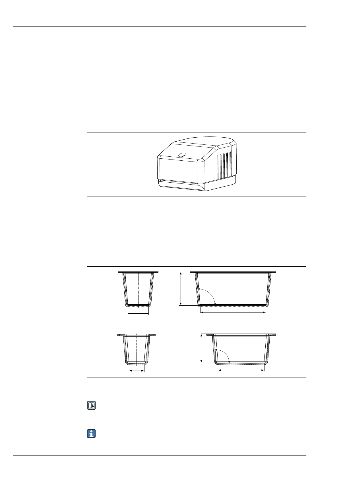
A0035756
6 Large calibration vessel (top) and small calibration vessel (bottom). Dimensions: mm (in)
Communication and data processing
For detailed information on calibration tools, see BA01309C
Communication with the transmitter
Always connect digital sensors with Memosens technology to a transmitter with Memosens
technology. Data transmission to a transmitter for analog sensors is not possible.
6 Endress+Hauser
Page 7

Turbimax CUS52D
Digital sensors can store measuring system data in the sensor. These include the following:
• Manufacturer data
• Serial number
• Order code
• Date of manufacture
• Calibration data
• Calibration date
• Number of calibrations
• Serial number of the transmitter used to perform the last calibration
• Operating data
• Temperature application range
• Date of initial commissioning
Dependability Maintainability
Easy handling
Sensors with Memosens technology have integrated electronics that store calibration data and other
information (e.g. total hours of operation or operating hours under extreme measuring conditions).
Once the sensor has been connected, the sensor data are transferred automatically to the transmitter
and used to calculate the current measured value. As the calibration data are stored in the sensor,
the sensor can be calibrated and adjusted independently of the measuring point. The result:
• Easy calibration in the measuring lab under optimum external conditions increases the quality of
the calibration.
• Pre-calibrated sensors can be replaced quickly and easily, resulting in a dramatic increase in the
availability of the measuring point.
• Thanks to the availability of the sensor data, maintenance intervals can be accurately defined and
predictive maintenance is possible.
• The sensor history can be documented on external data carriers and in evaluation programs.
• Thus, the current application of the sensors can be made to depend on their previous history.
Measured variable
Measuring range
Electrical connection
Input
• Turbidity
• Temperature
• Solids content
CUS52D Application
Turbidity 0.000 to 4000 FNU
Display range up to 9999 FNU
Solids 0 to 600 mg/l
Display range up to 3 g/l
0 to 2 200 mg/l
Display range up to 10 g/l
Temperature –20 to 85 °C (–4 to 185 °F)
Formazine
Kaolin
Diatomite
Power supply
The following connection options are available:
• via M12 connector (version: fixed cable, M12 connector)
• via sensor cable to the plug-in terminals of a sensor input on the transmitter (version: fixed cable,
end sleeves)
Endress+Hauser 7
Page 8
85 86
85
2DS
1
2
86
97 88 8798
97 88 8798
Sensor 1
Sensor 2
PK
GY
GN
YE
Sensor
85 86
85
1
2
86
97 88 8798
Sensor 1
PK
GY
GN
YE
BN
WH
Sensor
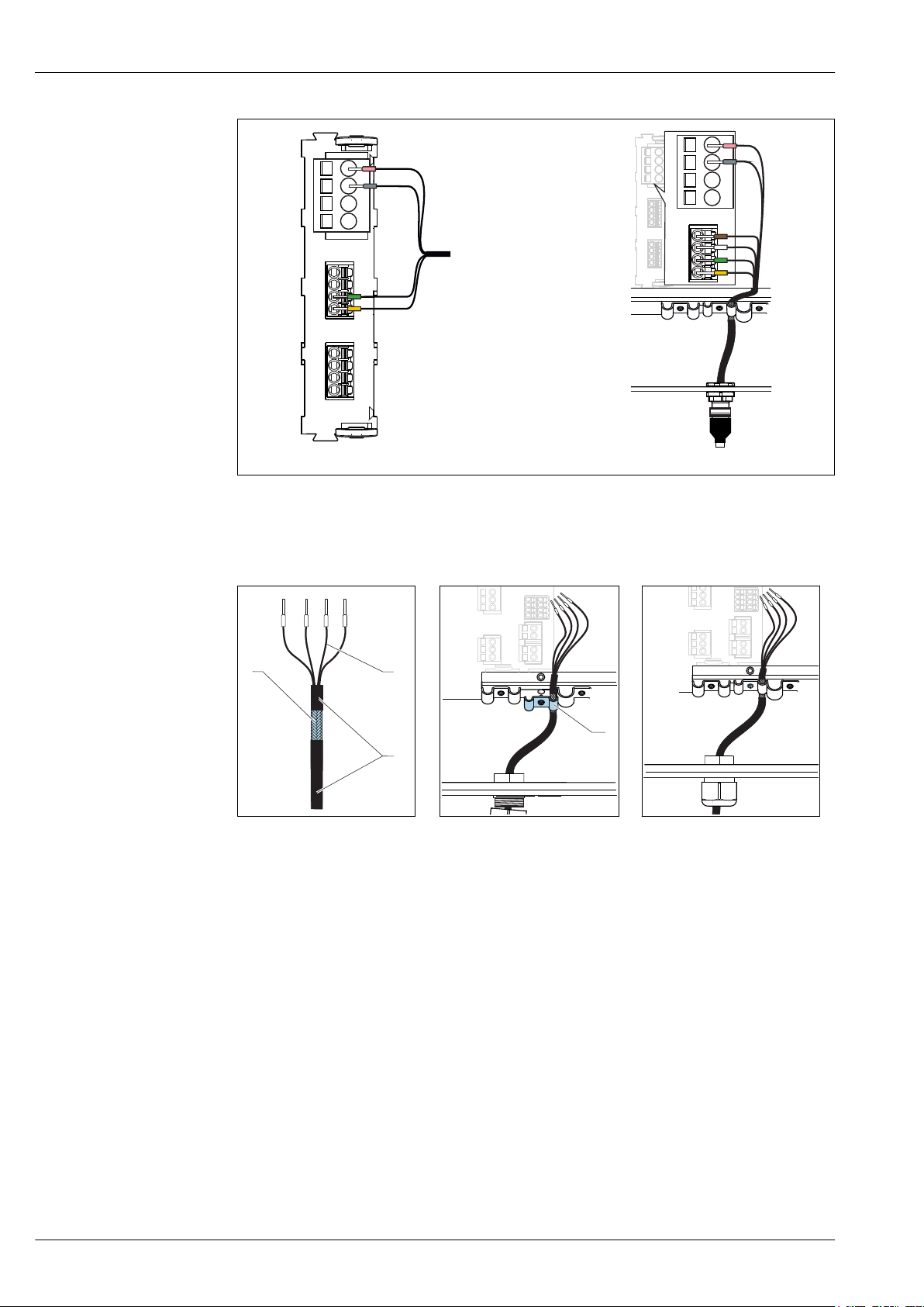
7 Sensor connection to sensor input (left) or via M12 connector (right)
1
2
3
4
Turbimax CUS52D
A0033092
Connecting the cable shield
Cable sample (does not necessarily correspond to the original cable supplied)
8 Terminated cable
1 Outer shield (exposed)
2 Cable cores with ferrules
3 Cable sheath (insulation)
9 Inserting the cable
4 Grounding clip
10 Tightening the screw
(2 Nm (1.5 lbf ft))
The cable shield is grounded by the
grounding clip
The maximum cable length is 100 m (328.1 ft).
8 Endress+Hauser
Page 9

Turbimax CUS52D
4
2
1
3
5
2
3
4
90°
Performance characteristics
Reference operating conditions
Maximum measured error
Repeatability
Long-term reliability Drift
Response time
20 °C (68 °F), 1013 hPa (15 psi)
Turbidity 2 % of the measured value or 0.1 FNU (the greater value applies in each case).
Solids < 5% of measured value or 1 % of the end of measuring range (the greater value applies
< 0.5 % of the measured value
Working on the basis of electronic controls, the sensor is largely free of drifts.
> 1 second, adjustable
Reference: measured value in recommended operational range, factory calibration
in each case). Applies for sensors that are calibrated to the particular measuring range
under analysis.
The measured error encompasses all inaccuracies of the measuring chain (sensor and
transmitter). However, it does not include the inaccuracy of the reference material used for
calibration.
For solids, the achievable measured errors depend very much on the media that are actually
present and may differ from the specified values. Extremely inhomogeneous media cause the
measured value to fluctuate and increase the measured error.
Detection limit
Detection limit in accordance with ISO 15839 in ultrapure water:
Application Measuring range Detection limit
Formazine 0 to 10 FNU (ISO 15839) 0.0015 FNU
Installation
Orientation Orientation in pipes
11 Permitted and unacceptable orientations in pipes
A0030698
Endress+Hauser 9
Page 10

Turbimax CUS52D
6
7
8
9
10
1
• Install the sensor in places with consistent flow conditions.
• The best installation location is in the ascending pipe (item 1). Installation in the horizontal pipe
(item 4) is also possible.
• Do not install the sensor in places where air spaces or bubbles occur (item 3) or where
sedimentation may occur (item 2).
• Avoid installation in the down pipe (item 5).
• Avoid fittings downstream from pressure reduction stages which can lead to outgassing.
Wall effects
Backscattering on the pipe wall may result in the distortion of measured values in the case of
turbidity values < 200 FNU. Therefore a pipeline diameter of at least 100 mm (3.9 in) is
recommended for reflecting materials (e.g. stainless steel). An assembly adjustment onsite is also
recommended.
Pipes made of stainless steel with diameter >DN 300 exhibit hardly any wall effects.
Black plastic pipes with diameter > DN 60 exhibit hardly any wall effects (<0.05 FNU). For this
reason, the use of black plastic pipes is recommended.
A0030704
12 Orientations for pipes and assemblies
• Install the sensor in such a way that the light beam is not reflected → 12, 10 (item 6).
• Avoid sudden changes in cross-section (item 9). Changes in cross-section should be gradual and
located as far away as possible from the sensor (item 10).
• Do not install the sensor directly downstream from a bend (item 7). Instead position it as far away
as possible from the bend (item 8).
Installation marking
A0030820
13 Installation marking for sensor alignment
1 Installation marking
10 Endress+Hauser
Page 11

Turbimax CUS52D
2
The installation marking on the sensor is aligned opposite the optical system.
Align the sensor against the flow direction.
‣
Mounting options
The installation angle is 90°.
The arrow points in the direction of
flow.
The optical windows in the sensor must
be aligned against the direction of flow.
The medium pressure may not exceed
2 bar (29 psi) for manual assembly
retraction.
A0022285
14 Installing with CUA451 retractable assembly
The installation angle is 0°.
The arrow points in the direction of
flow.
If the sensor is being used in open
‣
basins, install the sensor in such a
way that air bubbles cannot
accumulate on it.
15 Installing with immersion assembly
16 Installing with 2" clamp connection
A0022033
The installation angle is 90°.
The arrow points in the direction of
flow.
The optical windows in the sensor must
be aligned against the direction of flow.
A weld-in adapter is available as an
accessory for the installation → 11.
A0022032
The installation angle is 90°.
The arrow points in the direction of
flow.
The optical windows in the sensor must
be aligned against the direction of flow.
A0022034
17 Installing with CUA252 flow assembly
Endress+Hauser 11
Page 12

18 Installing with CUA262 flow assembly
60 ... 64
(2.36 ... 2.52)
> 100 (3.94)
36
(1.42)
19 Installing with standard Varivent connection
Turbimax CUS52D
The installation angle is 90°.
The arrow points in the direction of
flow.
The optical windows in the sensor must
be aligned against the direction of flow.
A0022281
The installation angle is 90°.
The arrow points in the direction of
flow.
The optical windows in the sensor must
be aligned against the direction of flow.
A0031130
A0031132
20 Installing with Varivent connection with extended
shaft
21 Pipe connection with weld-in adapter. Dimensions: mm (in)
For automatic sensor operation in pipe fittings or flow assemblies, there is the option of using the
ultrasonic cleaning system CYR52 (→ 20).
Bubbles result in errors in turbidity measurements. The effect of this interference can be minimized
by using a bubble trap (→ 21).
A0030819
12 Endress+Hauser
Page 13

Turbimax CUS52D
Environment
Ambient temperature range
Storage temperature
Degree of protection
Electromagnetic compatibility (EMC)
Process temperature range
–20 to 60 °C (–4 to 140 °F)
–20 to 70 °C (–4 to 158 °F)
IP 68 (1.8 m (5.91 ft) water column over 20 days, 1 mol/l KCl)
Interference emission and interference immunity as per
• EN 61326-1:2013
• EN 61326-2-3:2013
• NAMUR NE21: 2012
Process
Stainless steel sensor
–20 to 85 °C (–4 to 185 °F)
Plastic sensor
–20 to 60 °C (–4 to 140 °F)
Under high temperatures combined with extremely high or low pH values and chemical boundary
conditions, e.g. during CIP cleaning processes, the sensor has limited long-term stability.
To avoid damage to the sensor, only use the sensor in combination with a retractable assembly
in CIP cleaning processes. The retractable assembly allows the sensor to be removed from the
process during cleaning.
Process pressure range Stainless steel sensor
0.5 to 10 bar (7.3 to 145 psi) (abs.)
Plastic sensor
0.5 to 6 bar (7.3 to 87 psi)
Flow limit Minimum flow
No minimum flow required.
For solids which have a tendency to form deposits, ensure that sufficient mixing is performed.
Endress+Hauser 13
Page 14

Mechanical construction
Ø 40
(1.57)
NPT ¾“
G1
237.5 (9.35)
82.7 (3.26)
2 (0.08)
20.5 (0.81)
18.5 (0.73)
12.5
(0.49)
13.5
(0.53)
20.5
(0.81)
15
(0.59)
Dimensions Plastic version
Turbimax CUS52D
22 Dimensions of plastic sensor. Dimensions: mm (in)
A0042002
14 Endress+Hauser
Page 15

Turbimax CUS52D
Ø 40
(1.57)
NPT ¾“
G1
237.5 (9.35)
82.7 (3.26)
84.5 (3.33)
2 (0.08)
20.5 (0.81)
18.5 (0.73)
12.5
(0.49)
13.5
(0.53)
20.5
(0.81)
15
(0.59)
Stainless steel version
23 Dimensions of stainless steel sensor and stainless steel sensor with clamp connection (right). Dimensions:
mm (in)
A0030699
Endress+Hauser 15
Page 16

Turbimax CUS52D
18.5 (0.73)
82.7 (3.26)
237.5(9.35)
(1.57)
Ø 40
12.5
(0.49)
20.5
(0.81)
13.5
(0.53)
NPT ¾“
G1
15 (0.59)
2 (0.08)
20.5 (0.81)
42.5
(1.67)
22.5 (0.89)
35.5 (1.40)
13 (0.51)
A0035857
24 Dimensions of stainless steel sensor with standard Varivent connection (left) and extended shaft (right).
Dimensions: mm (in)
Compressed air cleaning
A0030691
25 Dimensions of sensor with compressed air cleaning. Dimensions: mm (in)
Compressed air cleaning accessory → 20
16 Endress+Hauser
Page 17

Turbimax CUS52D
45 (1.77)
58 (2.28)
60 (2.36)
43 (1.69)
86 (3.39)
30
(1.18)
Ø 40 (1.57)
9.5 (0.37)
Solid state reference
A0030821
26 Solid state reference Calkit CUS52D. Dimensions: mm (in)
Weight Plastic sensor
Plastic sensor: 0.72 kg (1.58 lb)
The specifications apply to the sensor with a 7 m (22.9 ft) cable.
Stainless steel sensor
With clamp 1.54 kg (3.39 lb)
Without clamp 1.48 kg (3.26 lb)
With Varivent connection, standard 1.84 kg (4.07 lb)
With Varivent connection, extended shaft 1.83 kg (4.04 lb)
The specifications apply to the sensor with a 7 m (22.9 ft) cable.
Materials
Sensor head: PEEK GF30 Stainless steel 1.4404 (AISI 316 L)
Sensor housing: PPS GF40 Stainless steel 1.4404 (AISI 316 L)
O-rings: EPDM EPDM
Optical windows Sapphire Sapphire
Process connections
Plastic and stainless steel sensor
G1 and NPT ¾'
Stainless steel sensor
• Clamp 2" (depending on sensor version)/DIN 32676
• Varivent N DN 65 - 125 standard immersion depth 22.5 mm
• Varivent N DN 65 - 125 immersion depth 42.5 mm
Plastic sensor Stainless steel sensor
Endress+Hauser 17
Page 18

Certificates and approvals
Turbimax CUS52D
mark
ISO 7027
EAC
Marine approvals
Scope of delivery
Product page
The product meets the requirements of the harmonized European standards. As such, it complies
with the legal specifications of the EU directives. The manufacturer confirms successful testing of the
product by affixing to it the mark.
The measurement method used in the sensor corresponds to the nephelometric turbidity method
according to ISO 7027-1:2016.
The product has been certified according to guidelines TP TC 004/2011 and TP TC 020/2011 which
apply in the European Economic Area (EEA). The EAC conformity mark is affixed to the product.
A selection of sensors have type approval for marine applications, issued by the following
classification societies: ABS (American Bureau of Shipping), BV (Bureau Veritas), DNV-GL (Det
Norske Veritas-Germanischer Lloyd) and LR (Lloyd’s Register). Details of the order codes of the
approved sensors, and the installation and ambient conditions, are provided in the relevant
certificates for marine applications on the product page on the Internet.
Ordering information
The delivery comprises:
• 1 sensor, version as ordered
• 1 Operating Instructions BA01275C
www.endress.com/cus52d
Product Configurator
Assemblies
On the product page there is a Configure button to the right of the product image.
1. Click this button.
The Configurator opens in a separate window.
2. Select all the options to configure the device in line with your requirements.
In this way, you receive a valid and complete order code for the device.
3. Export the order code as a PDF or Excel file. To do so, click the appropriate button on the right
above the selection window.
For many products you also have the option of downloading CAD or 2D drawings of the
selected product version. Click the CAD tab for this and select the desired file type using
picklists.
Accessories
The following are the most important accessories available at the time this documentation was
issued.
For accessories not listed here, please contact your Service or Sales Center.
‣
FlowFit CUA120
• Flange adapter for mounting turbidity sensors
• Product Configurator on the product page: www.endress.com/cua120
Technical Information TI096C
Flowfit CUA252
• Flow assembly
• Product Configurator on the product page: www.endress.com/cua252
Technical Information TI01139C
18 Endress+Hauser
Page 19

Turbimax CUS52D
Ø 53 (2.09)
30 (1.18)
36 (1.42)
Ø 64 (2.52)
Flowfit CUA262
• Weld-in flow assembly
• Product Configurator on the product page: www.endress.com/cua262
Technical Information TI01152C
Flexdip CYA112
• Immersion assembly for water and wastewater
• Modular assembly system for sensors in open basins, channels and tanks
• Material: PVC or stainless steel
• Product Configurator on the product page: www.endress.com/cya112
Technical Information TI00432C
Cleanfit CUA451
• Manual retractable assembly made of stainless steel with ball valve shut-off for turbidity sensors
• Product Configurator on the product page: www.endress.com/cua451
Technical Information TI00369C
Flowfit CYA251
• Connection: See product structure
• Material: PVC-U
• Product Configurator on the product page: www.endress.com/cya251
Technical Information TI00495C
Holder
Mounting material
Flowfit CUA250
• Flow assembly for water and wastewater applications
• Product Configurator on the product page: www.endress.com/cua250
Technical Information TI00096C
Built-in adapter
• For installing CUS52D in CUA250 or CYA251 assembly
• Order number: 71248647
Flexdip CYH112
• Modular holder system for sensors and assemblies in open basins, channels and tanks
• For Flexdip CYA112 water and wastewater assemblies
• Can be affixed anywhere: on the ground, on the coping stone, on the wall or directly onto railings.
• Stainless steel version
• Product Configurator on the product page: www.endress.com/cyh112
Technical Information TI00430C
Weld-in adapter for clamp connection DN 50
• Material: 1.4404 (AISI 316 L)
• Wall thickness 1.5 mm (0.06 in)
• Order number: 71242201
A0030841
27 Weld-in adapter. Dimensions: mm (in)
Endress+Hauser 19
Page 20

60 ... 64
(2.36 ... 2.52)
> 100 (3.94)
36
(1.42)
28 Pipe connection with weld-in adapter. Dimensions: mm (in)
76.4 (3.01)
65.7 (2.59)
Ø 40 (1.57
)
60 (2.36)
8.75
(0.34)
25
(0.98)
18 (0.71)
21.7
(0.85)
x
Turbimax CUS52D
A0030819
Compressed air cleaning
Compressed air cleaning for stainless steel sensors
• Pressure 1.5 to 2 bar (21.8 to 29 psi)
• Connection: 6 mm (0.24 in) or 8 mm (0.31 in)
• Materials: POM black, stainless steel
• Order number: 71242026
29 Compressed air cleaning for stainless steel sensors. Dimensions: mm (in)
X 6 mm (0.2 in) hose barb
Compressor
• For compressed air cleaning
• 230 V AC, order number: 71072583
• 115 V AC, order number: 71194623
Ultrasonic cleaning
Ultrasonic cleaning system CYR52
• For attachment to assemblies and pipes
• Product Configurator on the product page: www.endress.com/cyr52
Technical Information TI01153C
20 Endress+Hauser
A0030837
Page 21

Turbimax CUS52D
254 (10.0)
12 (0.5)
12 (0.5)
1
2
3
Bubble trap
Bubble trap
• For sensor CUS52D
• Process pressure: up to 3 bar (43.5 psi)
• Process temperature: 0 to 50 °C (32 to 122 °F)
• D 12 adapter with connection for degassing line (upper connection on the CUA252) is included in
the scope of delivery.
• Orifice plates for the following volume flows:
• < 60 l/h (15.8 gal/h)
• 60 to 100 l/h (15.8 to 26.4 gal/h)
• 100 l/h (26.4 gal/h)
• The degassing line is fitted with a PVC hose, backpressure hose valve and luer lock adapter.
• Order number, suitable for CUA252 assembly: 71242170
• Order number, suitable for assembly S of CUS31: 71247364
A0035757
30 Bubble trap. Dimensions: mm (in)
1 Inlet for medium (without hose system)
2 Outlet for bubbles (hose system is included in scope of delivery)
3 Outlet for medium (without hose system)
Solid state reference
Calibration vessel
CUY52-AA+560
• Calibration tool for CUS52D turbidity sensor
• Easy and reliable validation and calibration of CUS52D turbidity sensors.
• Product Configurator on the product page: www.endress.com/cuy52
Technical Information TI01154C
CUY52-AA+640
• Calibration vessel for CUS52D turbidity sensor
• Easy and reliable validation and calibration of CUS52D turbidity sensors.
• Product Configurator on the product page: www.endress.com/cuy52
Technical Information TI01154C
Endress+Hauser 21
Page 22

Page 23

Page 24

www.addresses.endress.com
 Loading...