

Page 1
BA00461C/07/EN/18.19
71438792
2019-01-31
Products Solutions Services
Operating Instructions
Turbimax CUS51D
Sensor for turbidity and solids content
Page 2

Page 3

Turbimax CUS51D Table of contents
Table of contents
1 About this document ................ 4
1.1 Warnings ............................ 4
1.2 Symbols used .......................... 4
1.3 Symbols on the device ................... 4
2 Basic safety instructions ............ 5
2.1 Requirements for the personnel ............ 5
2.2 Designated use ........................ 5
2.3 Occupational safety ..................... 5
2.4 Operational safety ...................... 6
2.5 Product safety ......................... 6
3 Product description ................. 7
3.1 Product design ......................... 7
4 Incoming acceptance and product
identification ..................... 12
4.1 Incoming acceptance ................... 12
4.2 Product identification ................... 12
4.3 Scope of delivery ...................... 13
4.4 Certificates and approvals ............... 13
12 Accessories ....................... 38
12.1 Assemblies .......................... 38
12.2 Holder .............................. 38
12.3 Compressed air cleaning ................ 38
13 Technical data .................... 40
13.1 Input ............................... 40
13.2 Performance characteristics .............. 40
13.3 Environment ......................... 42
13.4 Process ............................. 42
13.5 Mechanical construction ................ 42
Index .................................. 43
5 Installation ....................... 14
5.1 Mounting conditions ................... 14
5.2 Mounting the sensor ................... 14
5.3 Post-installation check .................. 20
6 Electrical connection .............. 21
6.1 Connecting the sensor .................. 21
6.2 Ensuring the degree of protection .......... 22
6.3 Post-connection check .................. 22
7 Commissioning .................... 23
7.1 Function check ....................... 23
8 Operation ......................... 24
8.1 Adapting the measuring device to the process
conditions ........................... 24
9 Diagnostics and troubleshooting ... 35
9.1 General troubleshooting ................. 35
10 Maintenance ...................... 36
10.1 Maintenance tasks ..................... 36
11 Repair ............................ 37
11.1 Return .............................. 37
11.2 Disposal ............................ 37
Endress+Hauser 3
Page 4
About this document Turbimax CUS51D
1 About this document
1.1 Warnings
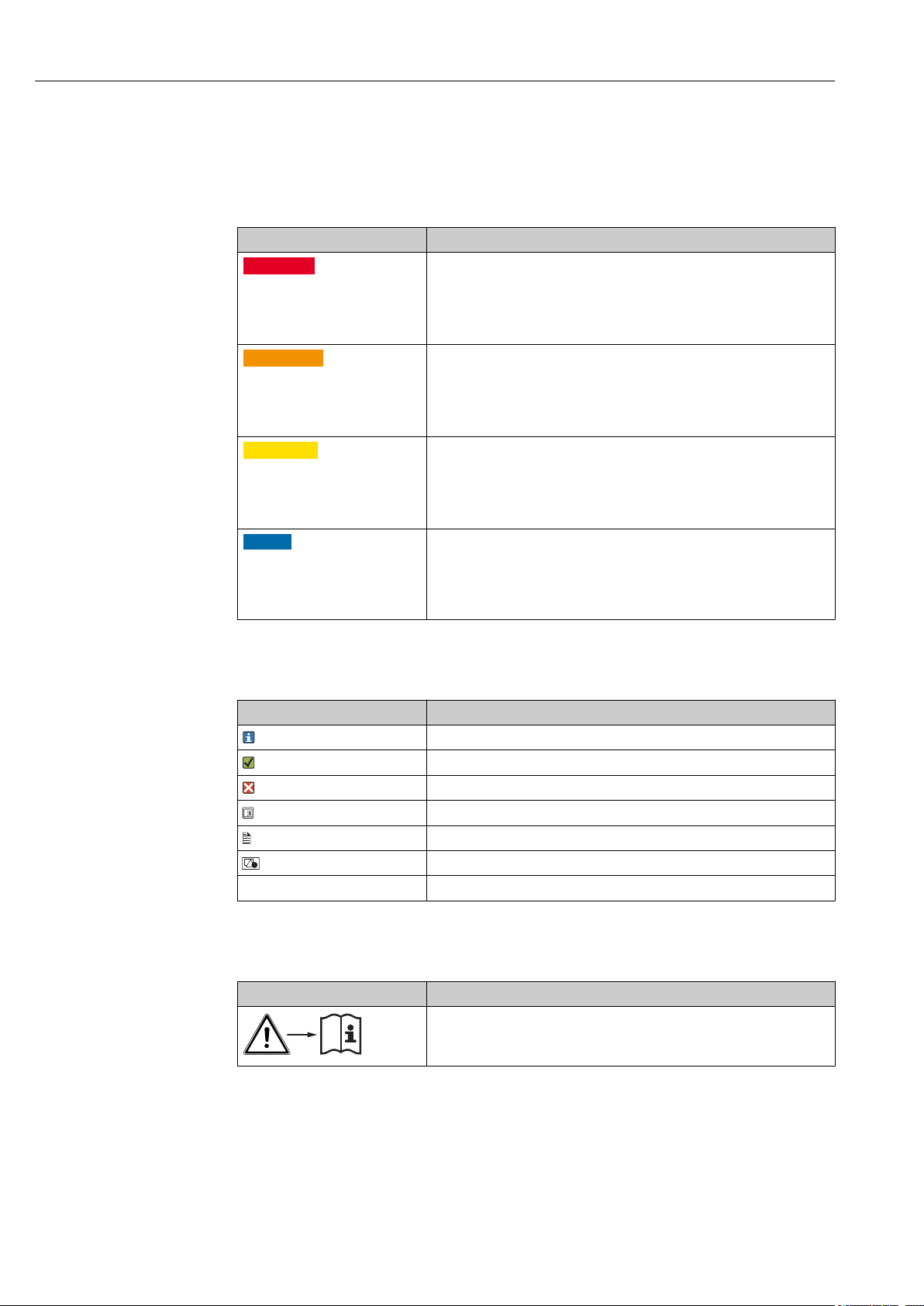
Structure of information Meaning
DANGER
L
Causes (/consequences)
If necessary, Consequences of
non-compliance (if applicable)
Corrective action
‣
WARNING
L
Causes (/consequences)
If necessary, Consequences of
non-compliance (if applicable)
Corrective action
‣
CAUTION
L
Causes (/consequences)
If necessary, Consequences of
non-compliance (if applicable)
Corrective action
‣
NOTICE
Cause/situation
If necessary, Consequences of
non-compliance (if applicable)
Action/note
‣
This symbol alerts you to a dangerous situation.
Failure to avoid the dangerous situation will result in a fatal or serious
injury.
This symbol alerts you to a dangerous situation.
Failure to avoid the dangerous situation can result in a fatal or serious
injury.
This symbol alerts you to a dangerous situation.
Failure to avoid this situation can result in minor or more serious injuries.
This symbol alerts you to situations which may result in damage to
property.
1.2 Symbols used
Symbol Meaning
Additional information, tips
Permitted or recommended
Not permitted or not recommended
Reference to device documentation
Reference to page
Reference to graphic
Result of a step
1.3 Symbols on the device
Symbol Meaning
Reference to device documentation
4 Endress+Hauser
Page 5

Turbimax CUS51D Basic safety instructions
2 Basic safety instructions
2.1 Requirements for the personnel
• Installation, commissioning, operation and maintenance of the measuring system may
be carried out only by specially trained technical personnel.
• The technical personnel must be authorized by the plant operator to carry out the
specified activities.
• The electrical connection may be performed only by an electrical technician.
• The technical personnel must have read and understood these Operating Instructions
and must follow the instructions contained therein.
• Faults at the measuring point may only be rectified by authorized and specially trained
personnel.
Repairs not described in the Operating Instructions provided must be carried out only
directly at the manufacturer's site or by the service organization.
2.2 Designated use
CUS51D is a sensor for measuring turbidity and solids content in water and wastewater.
The sensor is particularly suited for use in the following applications:
• Turbidity measurement in the outlet
• Solids content in sludge activation and recirculation
• Solids content in sludge treatment
• Filterable matter in outlet of WWTPs
Use of the device for any purpose other than that described, poses a threat to the safety of
people and of the entire measuring system and is therefore not permitted.
The manufacturer is not liable for damage caused by improper or non-designated use.
2.3 Occupational safety
As the user, you are responsible for complying with the following safety conditions:
• Installation guidelines
• Local standards and regulations
Electromagnetic compatibility
• The product has been tested for electromagnetic compatibility in accordance with the
applicable European standards for industrial applications.
• The electromagnetic compatibility indicated applies only to a product that has been
connected in accordance with these Operating Instructions.
Endress+Hauser 5
Page 6

Basic safety instructions Turbimax CUS51D
2.4 Operational safety
Before commissioning the entire measuring point:
1. Verify that all connections are correct.
2. Ensure that electrical cables and hose connections are undamaged.
3. Do not operate damaged products, and protect them against unintentional operation.
4. Label damaged products as defective.
During operation:
If faults cannot be rectified:
‣
products must be taken out of service and protected against unintentional operation.
2.5 Product safety
2.5.1 State of the art
The product is designed to meet state-of-the-art safety requirements, has been tested, and
left the factory in a condition in which it is safe to operate. The relevant regulations and
European standards have been observed.
6 Endress+Hauser
Page 7
Turbimax CUS51D Product description
1
2
3
4
3 Product description
3.1 Product design
The sensor is designed for continuous in-situ determination of interfaces and solids
content.
The sensor is designed as a 40 mm sensor that can be operated directly and completely in
the process without the need for further sampling (in-situ).
The sensor includes all necessary modules:
• Power supply
• Light sources
• Detectors,
Detectors record the measuring signals, digitize them and process them into a measured
value.
• Sensor microcontroller
This is responsible for controlling internal processes and transmitting data.
All data - including the calibration data - are stored in the sensor. The sensor can thus be
precalibrated and used at a measuring point, calibrated externally, or used for several
measuring points with different calibrations.
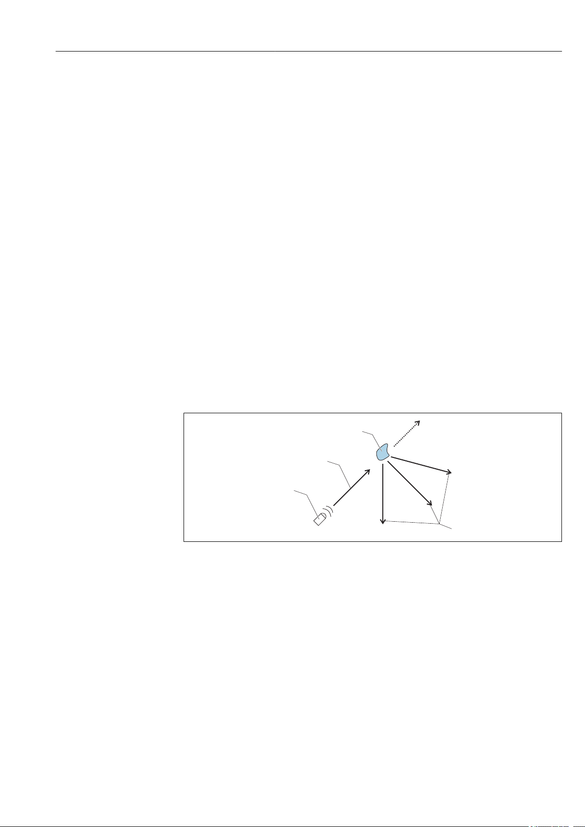
3.1.1 Measuring principle
For turbidity measurement a light beam is directed through the medium and is deflected
from its original direction by optically denser particles, e.g. particles of solid matter. This
process is also called scattering.
A0030850
1 Deflection of light
1 Light source
2 Light beam
3 Particle
4 Scattered light
The incident light is scattered in many directions, i.e. at different angles to the direction of
propagation. 2 angle ranges are of particular interest here:
• Light scattered at a 90° angle is used primarily for turbidity measurement in drinking
water.
• Light scattered at a 135° angle extends the dynamic range for high particle densities.
Endress+Hauser 7
Page 8
Product description Turbimax CUS51D
90°
135°
1
2
3
1
Ir
FNU
90°
135°
A0030846
2 Principle mode of operation of turbidity sensor
1 Light source
2 135° light receiver
3 90° light receiver
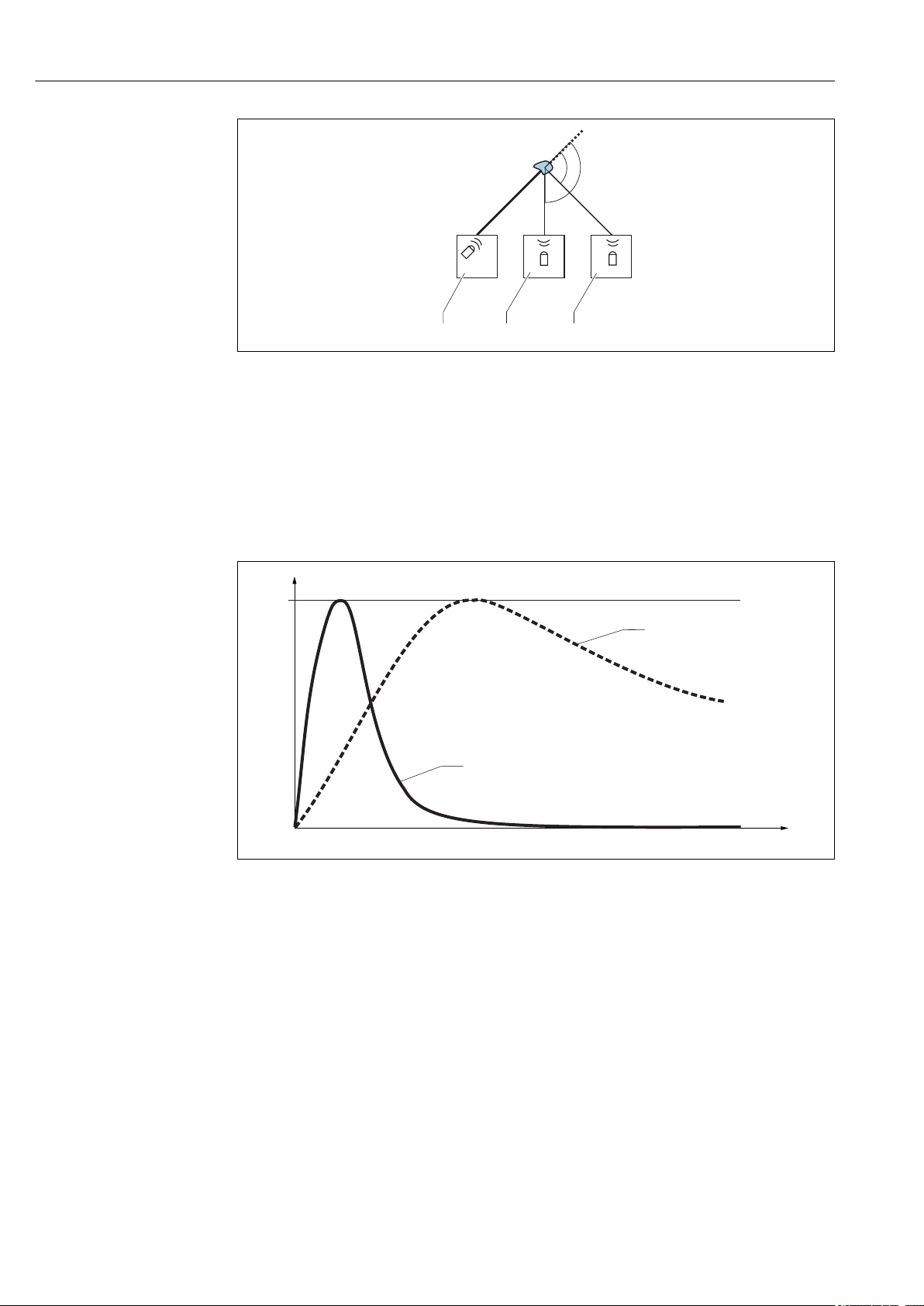
If the particle density in the medium is low, a large amount of light is scattered in the
90°channel and a small amount of light is scattered in the 135° channel. As the particle
density increases, this ratio shifts (more light in the 135° channel, less light in the 90°
channel).
3 Signal distribution as a function of the particle density
Ir Relative intensity
FNU Turbidity unit
The CUS51D turbidity sensor has 2 sensor units, which are independent of each other and
arranged in parallel. The application-dependent evaluation of both signals leads to stable
measured values.
8 Endress+Hauser
A0030849
Page 9

Turbimax CUS51D Product description
1
2
3
4
5
6
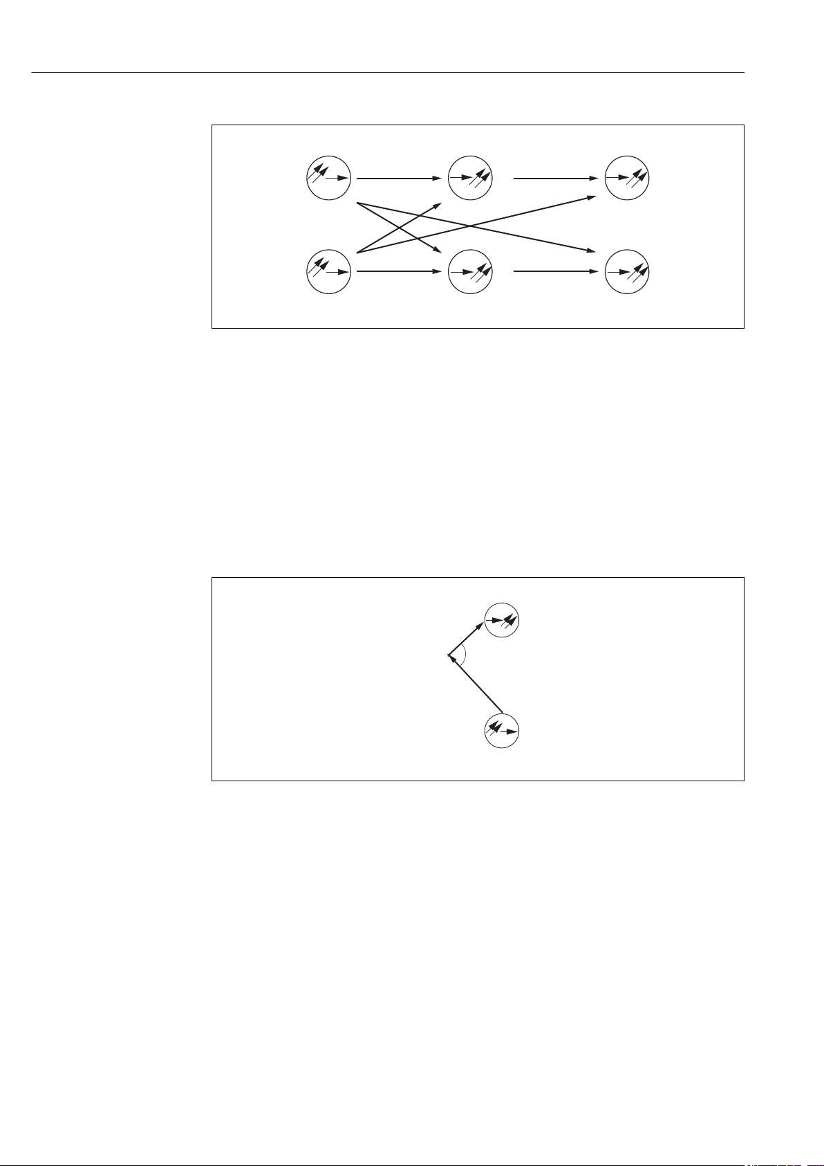
A0030845
4 Arrangement of light sources and light receivers
1, 2 Light sources 1 and 2
3, 5 135° light receiver
4, 6 90° light receiver
The sensor covers a broad range of turbidity and solids measurements thanks to the
optical arrangement with 2 light sources, each with 2 light receivers placed at different
angles (90° and 135°).
• As soon as the customer selects an application, e.g. activated sludge, the optical method
best suited for the particular measuring task is automatically activated in the sensor (e.g.
90° measurements with both light sources).
• The double sensing system (2 light sources with 2 receivers per source) largely
compensates for measured errors caused by fouling (4-beam pulsed light method
→ 9).
The sensor types available vary in terms of their measuring ranges and therefore the
range of available applications.
3.1.2 Measuring methods
4-beam pulsed light method
The method is based on 2 light sources and 4 light receivers. Long-life LEDs are used as
monochromatic light sources. These LEDs are pulsed alternately and generate 4 scattered
light signals per LED pulse at the receivers.
This offsets interference influences such as extraneous light, LED aging, fouling of
windows and absorption in the medium. Depending on the chosen application, different
scattered light signals are processed. The signal type, number and calculation are stored in
the sensor.
Endress+Hauser 9
Page 10
Product description Turbimax CUS51D
S
1
E
1-135
E
2-135
S
2
E
1-90
E
2-90
S
E
a
P
A0030847
5 4-beam pulsed light method
S1 S
E
90
E
135
Light source
2
Light receiver for 90° scattered light
Light receiver for 135° scattered light
90° scattered light method
Measurement is performed with a wavelength of 860 Nm (634.3 lbf ft), as described in
ISO 7027 / EN 27027.
The emitted light beam is scattered by the solid particles in the medium. The scattered
radiation generated in this way is measured by scattered light receivers, which are
arranged at an angle of 90° to the light sources. The turbidity of the medium is determined
by the amount of scattered light.
6 90° scattered light method
S Light source
E Receiver
P Particle
135° backscattered light method
The emitted light beam is scattered by the solid particles in the medium. The
backscattering generated is measured by scattered light receivers, which are arranged next
to the light sources. The turbidity of the medium is determined based on the quantity of
back-scattered light. It is possible to measure very high turbidity values with this type of
scattered light measurement.
10 Endress+Hauser
A0030852
Page 11

Turbimax CUS51D Product description
S
1
E
1
P
I
0
I
S
a
Is= I0· C · A· f(a)
A0030855
7 Principle of backscattered light method
IoIntensity of transmitted light
IsIntensity of scattered light
A Geometric factor
C Concentration
P Particle
f(α) Angle correlation
Endress+Hauser 11
Page 12

Incoming acceptance and product identification Turbimax CUS51D
4 Incoming acceptance and product
identification
4.1 Incoming acceptance
1. Verify that the packaging is undamaged.
Notify the supplier of any damage to the packaging.
Keep the damaged packaging until the issue has been resolved.
2. Verify that the contents are undamaged.
Notify the supplier of any damage to the delivery contents.
Keep the damaged goods until the issue has been resolved.
3. Check that the delivery is complete and nothing is missing.
Compare the shipping documents with your order.
4. Pack the product for storage and transportation in such a way that it is protected
against impact and moisture.
The original packaging offers the best protection.
Make sure to comply with the permitted ambient conditions.
If you have any questions, please contact your supplier or your local Sales Center.
4.2 Product identification
4.2.1 Nameplate
The nameplate provides you with the following information on your device:
• Manufacturer identification
• Order code
• Extended order code
• Serial number
• Safety information and warnings
Compare the information on the nameplate with the order.
‣
4.2.2 Product identification
Product page
www.endress.com/cus51d
Interpreting the order code
The order code and serial number of your product can be found in the following locations:
• On the nameplate
• In the delivery papers
Obtaining information on the product
1. Go to www.endress.com.
2. Call up the site search (magnifying glass).
3. Enter a valid serial number.
4. Search.
The product structure is displayed in a popup window.
12 Endress+Hauser
Page 13

Turbimax CUS51D Incoming acceptance and product identification
5. Click on the product image in the popup window.
A new window (Device Viewer) opens. All of the information relating to your
device is displayed in this window as well as the product documentation.
4.2.3 Manufacturer's address
Endress+Hauser Conducta GmbH+Co. KG
Dieselstraße 24
D-70839 Gerlingen
4.3 Scope of delivery
The delivery comprises:
• 1 Turbimax CUS51D sensor, version as ordered
• 1 Operating Instructions BA00461C
4.4 Certificates and approvals
4.4.1 mark
The product meets the requirements of the harmonized European standards. As such, it
complies with the legal specifications of the EU directives. The manufacturer confirms
successful testing of the product by affixing to it the mark.
4.4.2 Electromagnetic compatibility
Interference emission and interference immunity as per
• EN 61326-1:2013
• EN 61326-2-3:2013
• NAMUR NE21: 2012
4.4.3 EAC
The product has been certified according to guidelines TP TC 004/2011 and TP TC
020/2011 which apply in the European Economic Area (EEA). The EAC conformity mark
is affixed to the product.
Endress+Hauser 13
Page 14
Installation Turbimax CUS51D
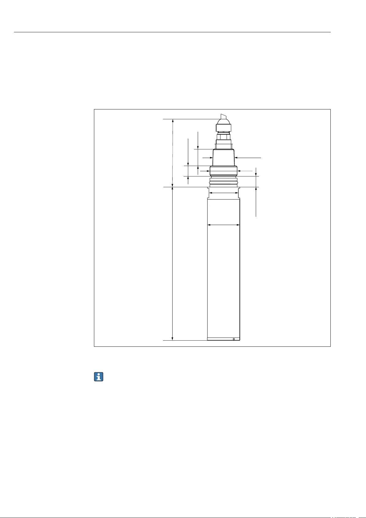
Ø 40
(1.57)
NPT ¾“
G1
82.7 (3.26)
188.5 (7.42)
12.5 (0.49)
20.5
(0.81)
13.5 (0.53)
36
(1.42)
5 Installation
5.1 Mounting conditions
5.1.1 Dimensions
8 Dimensions. Dimensions: mm (in)
Dimensions for compressed air cleaning → 38
5.2 Mounting the sensor
5.2.1 Measuring system
A complete measuring system comprises:
• Turbimax CUS51D turbidity sensor
• Liquiline CM44x multi-channel transmitter
• Assembly:
• Flexdip CYA112 assembly and Flexdip CYH112 holder or
• Retractable assembly, e.g. Cleanfit CUA451
A0030853
14 Endress+Hauser
Page 15

Turbimax CUS51D Installation
1
2
3
1
4
5
2
3
5
4
A0030844
9 Measuring system with immersion assembly (example)
1 Flexdip CYH112 holder
2 Liquiline CM44x multi-channel transmitter
3 Protective cover
4 Flexdip CYA112 assembly
5 Turbimax CUS51D turbidity sensor
10 Measuring system with immersion assembly (example)
1 Liquiline CM44x multi-channel transmitter
2 Protective cover
3 Flexdip CYH112 holder
4 Flexdip CYA112 assembly
5 Turbimax CUS51D turbidity sensor
Endress+Hauser 15
A0030856
Page 16

Installation Turbimax CUS51D
3
4
2
a
A0030843
11 Measuring system with retractable assembly (example)
1 Turbimax CUS51D turbidity sensor
2 Liquiline CM44x multi-channel transmitter
3 Cleanfit CUA451 retractable assembly
4 Direction of flow
5.2.2 Installation examples
Pipe installation
Arrow 1 points in the direction of flow.
The installation angle α must not exceed
90°.
The recommended installation angle is
75°.
The optical windows in the sensor must
be aligned either parallel to the direction
of flow (α = 90°) or against the direction
of flow (α < 90°).
The medium pressure may not exceed
A0031134
12 Installing with retractable assembly
1 Direction of flow
2 bar (29 psi) for manual assembly
retraction.
The installation angle is 90°.
For turbidity measurements < 200 FNU,
the backscattering of the internal surfaces
of the assembly causes distortions in the
measured values.
A0035858
13 Installing with CYA251 flow assembly
The following diagram shows different installation scenarios in pipes, indicating whether
or not they are permitted.
16 Endress+Hauser
Page 17

Turbimax CUS51D Installation
4
5
2
2
1
3
3
A0030848
14 Orientations and positions (with CUA451 retractable assembly )
• When using reflective materials (e.g. stainless steel), the pipe diameter must be at least
100 mm (3.9 in). An onsite calibration is recommended.
• Install the sensor in places with consistent flow conditions.
• The best installation location is in the ascending pipe (item 1). Installation is also
possible in the horizontal pipe (item 5).
• Do not install in places where air spaces or bubbles occur (item 3) or where
sedimentation may occur (item 2).
• Avoid installation in the down pipe (item 4).
• When measuring turbidity < 200 FNU, the backscattering of the pipe wall causes
distortions in the measured values. For this reason, a multipoint calibration is
recommended here.
• Avoid fittings downstream from pressure reduction stages which can lead to outgassing.
Endress+Hauser 17
Page 18

Installation Turbimax CUS51D
2
3
4
1
4
5
Immersion operation
Fixed installation with wastewater assembly
A0012965
15 Installation secured on railing
1 Turbimax CUS51D turbidity sensor
2 Wastewater assembly Flexdip CYA112
3 Flexdip CYH112 holder
4 Rail
A0013383
16 Installation with upright post
1 Flexdip CYH112 holder
2 Liquiline CM44x multi-channel transmitter
3 Protective cover
4 Wastewater assembly Flexdip CYA112
5 Turbimax CUS51D turbidity sensor
18 Endress+Hauser
Page 19

Turbimax CUS51D Installation
2
3
4
5
1
4
5
6
This type of installation is particularly suitable for strong or turbulent flow
(> 0.5 m/s (1.6 ft/s)) in basins or channels.
Installation with chain retainer
17 Chain retainer on railing
1 Turbimax CUS51D turbidity sensor
2 Wastewater assembly Flexdip CYA112
3 Chain of Flexdip CYH112 holder
4 Flexdip CYH112 holder
4 Rail
A0013384
18 Chain retainer on upright post
1 Rail
2 Liquiline CM44x multi-channel transmitter
3 Protective cover
4 Chain of Flexdip CYH112 holder
5 Wastewater assembly Flexdip CYA112
6 Turbimax CUS51D turbidity sensor
A0037077
The chain retainer is particularly suitable for applications that require a sufficient distance
between the mounting location and the edge of the aeration basin. As the assembly is
freely suspended, any vibration of the upright post is practically ruled out. The swinging
movement of the chain retainer enhances the self-cleaning effect of the optics.
Mounting the cleaning unit
A0031105
19 Turbimax CUS51D sensor with cleaning unit
Endress+Hauser 19
Page 20

Installation Turbimax CUS51D
1
1
2
The cleaning unit is particularly suitable for clear water and media with a high fat content
that tend to cause heavy buildup.
Mount the cleaning unit as follows:
1. Fit the cleaning unit onto the sensor as far as it will go.
2. Locate the two LEDs (they are installed at an angle and have a bright enclosure).
3. Position the cleaning unit in such a way that the nozzle is located at the side of the
two LEDs (→ 20).
4. Fix the cleaning unit in place with the securing screw (max. torque:
0.5 Nm (0.37 lbf ft).
5. Insert the compressed air hose of the compressor into the hose connection.
A0030860
20 Aligning the cleaning unit
1 LEDs
2 Nozzle
21 Fixing the cleaning unit
1 Hose connection
2 Fixing screw
5.3 Post-installation check
Put the sensor into operation only if the following questions can be answered with "yes":
• Are the sensor and cable undamaged?
• Is the orientation correct?
• Has the sensor been installed in the process connection, and does not suspend freely
from the cable?
A0030861
20 Endress+Hauser
Page 21

Turbimax CUS51D Electrical connection
85 86
85
2DS
1
2
86
97 88 8798
97 88 8798
Sensor 1
Sensor 2
PK
GY
GN
YE
Sensor
85 86
85
1
2
86
97 88 8798
Sensor 1
PK
GY
GN
YE
BN
WH
Sensor
6 Electrical connection
WARNING
L
Device is live!
Incorrect connection may result in injury or death!
The electrical connection may be performed only by an electrical technician.
‣
The electrical technician must have read and understood these Operating Instructions
‣
and must follow the instructions contained therein.
Prior to commencing connection work, ensure that no voltage is present on any cable.
‣
6.1 Connecting the sensor
The following connection options are available:
• via M12 connector (version: fixed cable, M12 connector)
• via sensor cable to the plug-in terminals of a sensor input on the transmitter (version:
fixed cable, end sleeves)
A0033092
22 Sensor connection to sensor input (left) or via M12 connector (right)
Endress+Hauser 21
Page 22

Electrical connection Turbimax CUS51D
1
2
3
4
Connecting the cable shield
Cable sample (does not necessarily correspond to the original cable supplied)
23 Terminated cable
1 Outer shield (exposed)
2 Cable cores with ferrules
3 Cable sheath (insulation)
24 Inserting the cable
4 Grounding clip
25 Tightening the screw
(2 Nm (1.5 lbf ft))
The cable shield is grounded by the
grounding clip
The maximum cable length is 100 m (328.1 ft).
6.2 Ensuring the degree of protection
Only the mechanical and electrical connections which are described in these instructions
and which are necessary for the required, designated use, may be carried out on the device
delivered.
Exercise care when carrying out the work.
‣
Individual types of protection permitted for this product (impermeability (IP), electrical
safety, EMC interference immunity) can no longer be guaranteed if, for example :
• Covers are left off
• Different power units to the ones supplied are used
• Cable glands are not sufficiently tightened (must be tightened with 2 Nm (1.5 lbf ft) for
the permitted level of IP protection)
• Unsuitable cable diameters are used for the cable glands
• Modules are not fully secured
• The display is not fully secured (risk of moisture entering due to inadequate sealing)
• Loose or insufficiently tightened cables/cable ends
• Conductive cable strands are left in the device
6.3 Post-connection check
Device condition and specifications Notes
Are the sensor, assembly, or cables free from damage on the
outside?
Electrical connection Notes
Are the mounted cables strain-relieved and not twisted?
Is a sufficient length of the cable cores stripped, and are the cores
positioned in the terminal correctly?
Are all the screw terminals properly tightened? Tighten
22 Endress+Hauser
Are all cable entries mounted, tightened and leak-tight? For lateral cable entries, make sure the
Are all cable entries installed downwards or mounted laterally?
Visual inspection
Check the fit (by pulling gently)
cables loop downwards to allow water to
drip off
Page 23

Turbimax CUS51D Commissioning
7 Commissioning
7.1 Function check
Prior to initial commissioning, ensure that:
• The sensor is correctly installed
• The electrical connection is correct.
Endress+Hauser 23
Page 24

Operation Turbimax CUS51D
0
5
10 15 20 25 30
35
40
45
50
55
60 100 110 120 130 140 150 160
0
1000
9999
2000
3000
4000
5000
6000
7000
8000
9000
TiO2
Kaolin
Kieselguhr (SiO2)
Formazine
Turbidity (FNU)
0
5
10 15 20 25 30
35
40
45
50
55
6080859095 100
Digested sludge
Excess sludge
Activated sludge
Thin sludge
Sludge univ.
8 Operation
8.1 Adapting the measuring device to the process
conditions
8.1.1 Applications
The sensor permits measurements in a wide variety of applications. The measuring
method is set automatically by selecting the relevant application.
"Clear water" application type
Application Method Measuring range
Formazine 135° - single-channel measurement 0 to 4000 FNU
Display range up to 9999 FNU
Kaolin 135° - single-channel measurement 0 to 5 g/l
TiO2 (titanium dioxide) 135°, 4-beam pulsed light 0.2 to 150 g/l
SiO2 (silicon dioxide) 135°, 4-beam pulsed light 5 to 100 g/l
A0030862-EN
"Solids" application type
Application Method Measuring range
Thin sludge 135° turbidity, single-channel 0 to 5 g/l
Sludge activation 90°, 4-beam pulsed light 2 to 15 g/l
Waste activated sludge 135°, 4-beam pulsed light 3 to 50 g/l
Sludge, univ. 135°, single-channel (for low TS content) 0 to 50 g/l
135°, 4-beam pulsed light (for high TS content)
Digested sludge 135° turbidity, single-channel 5 to 100 g/l / 300 g/l
24 Endress+Hauser
A0038988-EN
Page 25

Turbimax CUS51D Operation
Fields of application
Application
(models)
Formazine Industrial water, WWTP outlet FNU / NTU
Kaolin Filterable matter, industrial water, WWTP outlet, low
SiO
2
TiO
2
Thin sludge Thin sludge from activated sludge to clear water g/l; ppm; %
Activated sludge Activated sludge basin and similar media g/l; ppm; % X
Waste activated
sludge
Sludge, univ. Universal usage for clear water to sludge with high
Digested sludge Contaminated sludge, black homogeneous g/l; ppm; %
1) Contamination compensation with 4-beam pulsed light
Fields of application/use Unit Compen
mg/l; g/l;
concentrations of activated sludge
SiO2, mineral-based solids (sand) g/l; ppm; % X
TiO2, (white media) g/l; ppm; % X
Universal usage for sludge in wastewater sector between 5
and 50 g/l (activated sludge, return activated sludge, ...)
concentrations of solids, e.g. sludge extraction in thickeners.
0 g/l to 50 g/l
ppm; %
g/l; ppm; % X
g/l; ppm; % X
Fields of use and associated applications → 25
sation*
1)
NOTICE
Multiple scattering in the following applications: formazine, kaolin and thin sludge
If the specific operational range is exceeded, the measured value displayed by the sensor
can decrease despite increasing turbidity or increasing TS content. The indicated
operational range is reduced in the case of highly absorbing (e.g. dark) media.
In the case of highly absorbing (e.g. dark) media, determine the operational range
‣
experimentally beforehand.
8.1.2 Calibration
The sensor is precalibrated on leaving the factory. It can therefore be used in a wide variety
of applications (e.g. clear water measurements) without the need for additional
calibration. The factory calibrations are based on a 3-point calibration in each case. The
formazine application is already fully calibrated and can be used without any further
calibration.
All other applications are precalibrated with reference samples and require calibration to
the corresponding application.
In addition to the factory calibration data, which cannot be modified, the sensor has five
other data records to be used for storing process calibrations.
Application selection
During initial commissioning or calibration at the CM44x, select the appropriate
‣
application for your field of application.
Application: Wastewater
Field of application Application
Inlet Waste activated sludge (g/l, %TS),
Turbidity (formazine (FNU, NTU), thin sludge (mg/l, g/l))
Primary sludge extraction, primary
clarification
Waste activated sludge (g/l, %TS),
Digested sludge (g/l, %TS)
Endress+Hauser 25
Page 26

Operation Turbimax CUS51D
Field of application Application
Activated sludge basin,
0 to 5 g/l range, e.g. SBR
Activated sludge basin,
2 to 15 g/l range
Sequencing batch reactors
Range from 0 to approx. 50 g/l
Recirculation pipe Waste activated sludge (g/l, %TS)
Waste activated sludge extraction Waste activated sludge (g/l, %TS), digested sludge (g/l, %TS)
Sludge thickener (primary sludge) Waste activated sludge (g/l, %TS),
Digester inlet Waste activated sludge (g/l, %TS),
Digester outlet (sludge) Digested sludge (g/l, %TS),
WWTP outlet Turbidity (formazine (FNU, NTU), kaolin (mg/l, g/l)),
Sand filter monitoring Turbidity (formazine (FNU, NTU), thin sludge (mg/l, g/l))
Thin sludge (mg/l, g/l)
Activation (mg/l, g/l),
Waste activated sludge (g/l, %TS),
Universal model (mg/l, g/l, %TS)
For applications with wide dynamic range, from clear water to high
solids content
Digested sludge (g/l, %TS)
Digested sludge (g/l, %TS)
Waste activated sludge (g/l, %TS),
thin sludge (mg/l, g/l)
Preferred applications are highlighted in bold.
Application: process water
Field of application Application
Inlet Turbidity (formazine (FNU, NTU), kaolin (mg/l, g/l))
Process control SiO2 (ppm, g/l), TiO2 (ppm, g/l)
Filter flushing Turbidity (formazine (FNU, NTU), kaolin (mg/l, g/l)), thin sludge (mg/l, g/l)
Sedimentation tank Thin sludge (mg/l, g/l), waste activated sludge (g/l, %TS), digested sludge (g/l,
%TS)
Process water Turbidity (formazine (FNU, NTU), kaolin (mg/l, g/l), SiO2 (ppm, g/l), TiO2 (ppm,
g/l))
Process sludges Turbidity (formazine (FNU, NTU), kaolin (mg/l, g/l), SiO2 (ppm, g/l), TiO2 (ppm,
g/l))
Preferred applications are highlighted in bold.
Selecting the calibration type
1 to 5 points can be calibrated for all applications.
The following recommendation describes the usual calibration types.
Model 1-point calibration
(in medium)
Formazine X
Kaolin X
SiO
2
TiO
2
Thin sludge X
Activated sludge X
Univ. sludge X
At least 2-point calibration
(outside medium)
X
X
26 Endress+Hauser
Page 27

Turbimax CUS51D Operation
Model 1-point calibration
(in medium)
Waste activated sludge X
Digested sludge X
At least 2-point calibration
(outside medium)
The "thin sludge" model enables measurements in any sludge applications from 0 to 5
g/l. The "univ. sludge" model enables measurements in any sludge applications from
0 to 50 g/l. These models can be calibrated at a single point in the process during
operation.
1-point and 2-point calibrations are based on the data record stored internally in the
device. Calibration at 3 or more points always causes the measuring curve to be
recalculated.
For multipoint calibrations, the calibration points should always cover the complete
measuring range of the application. Points outside the specified measuring range of
the application (model) may not be selected.
A calibration with zero water (0 g/l) will result in unusable calibrations for the following
applications:
• Activated sludge
• Waste activated sludge
• Digested sludge
• SiO
2
• TiO
2
1-point calibration
The measured error between the measured value of the sensor and the laboratory
measured value is too large. This is corrected by a 1-point calibration.
Endress+Hauser 27
Page 28

Operation Turbimax CUS51D
1 2 3 4 5 6 7 8 9
1
2
3
4
5
6
7
8
9
x
y
A0039320
26 Principle of a 1-point calibration
x Measured value
y Target sample value
Blue Factory calibration
Red Application calibration
1. Select data record.
2. Set the calibration point in the medium and enter the target sample value (laboratory
value).
With 1-point calibration, the sensor can remain immersed in the process medium.
1. For the laboratory measurement, take a sample of the medium in the direct vicinity
of the sensor.
2. Give the sample to the laboratory so that the turbidity or solids content can be
determined.
3. Select a data record on the CM44x transmitter.
4. If possible, start the calibration at the same time as the sampling procedure and enter
the laboratory value of the sample as the set point.
5. Enter an approximate value as the set point if no laboratory value is available during
calibration.
As soon as the laboratory value is available, amend the set point on the
transmitter.
2-point calibration
Measured value deviations are to be compensated for at 2 different points in an
application (e.g. the maximum and minimum value of the application). This aims to ensure
a maximum level of accuracy between these two extreme values.
28 Endress+Hauser
Page 29

Turbimax CUS51D Operation
1 2 3 4 5 6 7 8 9
1
2
3
4
5
6
7
8
9
x
y
A0039325
27 Principle of a 2-point calibration
x Measured value
y Target sample value
Blue Factory calibration
Red Application calibration
1. Select a data record.
2. Set 2 different calibration points in the medium and enter the corresponding set
points.
A linear extrapolation is performed outside the calibrated operational range (gray
line).
The calibration curve must be monotonically increasing.
Endress+Hauser 29
Page 30

Operation Turbimax CUS51D
1 2 3 4 5 6 7 8 9
1
2
3
4
5
6
7
8
9
x
y
Multipoint calibration
A0039322
28 Principle of multipoint calibration (3 points)
x Measured value
y Target sample value
Blue Factory calibration
Red Application calibration
1. Select data record.
2. Set 3 different calibration points in the medium and specify the corresponding set
points.
A linear extrapolation is performed outside the calibrated operational range (gray
line).
The calibration curve must be monotonically increasing.
CAUTION
L
Acid or medium
Risk of injury, damage to clothing and the system!
Switch off the cleaning unit before removing the sensor from the medium.
‣
Wear protective goggles and safety gloves.
‣
Clean away splashes on clothes and other objects.
‣
30 Endress+Hauser
Page 31

Turbimax CUS51D Operation
1. Take a sample from the process (e.g.
10 l (2.6 gal) bucket).
A0020482
2. Wait until the sludge components
have settled.
A0035855
3. Siphon off the excess water (if
possible) in order to increase the
concentration of the sample.
Stir the sample to make it more
homogeneous.
A0035856
4. Remove a portion of the sample for
laboratory analysis.
A0020485
5. Transfer a defined amount of the
sample (e.g. 2 l (0.5 gal)) to the
calibration vessel (bucket).
Continue stirring the sample to
maintain homogeneity.
A0020486
Calibration of the CUS51D sensor
Preparing the CUS51D sensor for calibration
1. Clean the optical components (windows) of the sensor with water and a brush.
2. Place the sensor into the calibration vessel.
The sensor must be placed in the sample at an angle, not vertically. This prevents air
bubbles from adhering to the windows.
Endress+Hauser 31
Page 32

Operation Turbimax CUS51D
>10
(0.39)
~10 (0.39)
1
2
A0020487
29 Immersing the sensor
Observe the following:
• Sensor LEDs should be directed at the center of the calibration vessel.
• The minimum distance of the sensor to the vessel wall is 10 mm (0.4 in).
• The sensor should be distanced as far as possible from the bottom of the vessel, but at
least 10 mm (0.4 in) of the sensor must be immersed.
Secure the sensor in this position (ideally using a laboratory stand).
‣
A0030900
30 Positioning the sensor. Dimensions: mm (in)
1 Beam direction of LEDs
2 LEDs
Note the following during calibration:
• The calibration points should cover the complete measuring range.
• During calibration, ensure that the medium is well homogenized (use a magnetic
stirrer).
• Determine the laboratory measured values with utmost care (the quality of the
laboratory measurement has a direct influence on the accuracy of the sensor).
• Apply maximum precision when dosing volumes for the sample and the dilution water
(use a graduated cylinder).
• Air bubbles on optical components significantly interfere with the calibration result. For
this reason, remove air bubbles before every calibration action.
• Make sure the medium is always well mixed (homogeneity).
32 Endress+Hauser
Page 33

Turbimax CUS51D Operation
H O
2
H O
2
• Avoid temperature changes during the calibration.
Ensure that the temperatures of the dilution water and the medium are as identical as
possible.
• Do not alter the position of the sensor during calibration.
• It is also possible to edit the calibration set points in the CM44x at a later stage (e.g. if
the reference value of the laboratory measurement is not yet known at the time of
calibration).
Perform the calibration (example of a 3-point calibration)
1. Select a data record on the CM44x transmitter.
2. Wait at least 1 minute (to stabilize).
3. Start the calibration for measuring point 1 (e.g.2 l (0.5 gal) sample with a
concentration of 6 g/l).
4. Enter the value of the sample determined in the laboratory as the set point (e.g. 6
g/l) or edit the value later.
A0020489
5. Perform a 1:2 dilution of the sample. Add water (2 l (0.5 gal)), results in 3 g/l in the
example.
A0030901
6. Avoid air bubbles beneath the sensor.
7. Calibrate measuring point 2. For the set point, enter half of the laboratory value.
8. Perform a 1:3 dilution of the sample. Add water (2 l (0.5 gal)), results in 2 g/l in the
example.
9. Avoid air bubbles beneath the sensor.
10. Calibrate measuring point 3. For the set point, enter one third of the laboratory
value, or edit the value at a later stage.
The calibration can also be performed in increasing concentrations (less advisable).
Endress+Hauser 33
A0030902
Page 34

Operation Turbimax CUS51D
Stability criterion
During calibration, the measured values provided by the sensor are checked to ensure they
are constant. The maximum deviations that may occur in measured values during a
calibration are defined in the stability criterion.
The specifications comprise the following:
• The maximum permitted deviation in temperature measurement
• The maximum permitted deviation in measured value as a %
• The minimum time frame in which these values must be maintained
The calibration resumes as soon as the stability criteria for signal values and temperature
have been reached. If these criteria are not met in the maximum time frame of 5 minutes,
no calibration is performed - a warning is issued.
The stability criteria are used to monitor the quality of the individual calibration points in
the course of the calibration process. The aim is to achieve the highest possible calibration
quality in the shortest possible time frame while taking external conditions into account.
For calibrations in the field in adverse weather and environmental conditions, the
measured value windows selected can be suitably large and the time frame selected
can be suitably short.
8.1.3 Cyclic cleaning
For cyclic cleaning, compressed air is the most suitable option. The cleaning unit is either
supplied or can be retrofitted, and is attached to the sensor head. The following settings
are recommended for the cleaning unit:
Type of fouling Cleaning interval Cleaning duration
Severe fouling with rapid buildup of deposits 5 min 10 s
Low risk of fouling 10 min 10 s
34 Endress+Hauser
Page 35

Turbimax CUS51D Diagnostics and troubleshooting
9 Diagnostics and troubleshooting
9.1 General troubleshooting
When troubleshooting, the entire measuring point must be taken into account:
• Transmitter
• Electrical connections and cables
• Assembly
• Sensor
The possible causes of error in the following table relate primarily to the sensor.
Problem Testing Solution
No display, no sensor reaction • Power supplied to transmitter?
• Sensor connected correctly?
• Buildup on optical windows?
Display value too high or too low • Buildup on optical windows?
• Sensor calibrated?
Display value fluctuating greatly Is the mounting location correct? • Select a different mounting location
• Connect mains voltage
• Connect sensor correctly
• Clean sensor
• Cleaning
• Calibration
• Adjust the measured value filter
Pay attention to the troubleshooting information in the Operating Instructions for the
transmitter. Check the transmitter if necessary.
Endress+Hauser 35
Page 36

Maintenance Turbimax CUS51D
10 Maintenance
You must perform maintenance tasks at regular intervals.
‣
We recommend setting the maintenance times in advance in an operations journal or log.
The maintenance cycle primarily depends on the following:
• The system
• The installation conditions
• The medium in which measurement takes place
CAUTION
L
Acid or medium
Risk of injury, damage to clothing and the system!
Switch off the cleaning unit before removing the sensor from the medium.
‣
Wear protective goggles and safety gloves.
‣
Clean away splashes on clothes and other objects.
‣
10.1 Maintenance tasks
10.1.1 Clean sensor
Sensor fouling can affect the measurement results and even cause a malfunction.
The sensor must be cleaned regularly to ensure reliable measurement results. The
frequency and intensity of the cleaning process depend on the medium.
Clean the sensor:
• As specified in the maintenance schedule
• Before every calibration
• Before returning it for repairs
Type of fouling Cleaning measure
Lime deposits
Dirt particles on the optics
After cleaning:
Rinse the sensor thoroughly with water.
‣
Immerse the sensor in 1 to 5% hydrochloric acid (for several minutes).
‣
Clean the optics with a cleaning cloth.
‣
36 Endress+Hauser
Page 37

Turbimax CUS51D Repair
11 Repair
11.1 Return
The product must be returned if repairs or a factory calibration are required, or if the
wrong product was ordered or delivered. As an ISO-certified company and also due to legal
regulations, Endress+Hauser is obliged to follow certain procedures when handling any
returned products that have been in contact with medium.
To ensure the swift, safe and professional return of the device:
Refer to the website www.endress.com/support/return-material for information on the
‣
procedure and conditions for returning devices.
11.2 Disposal
The device contains electronic components. The product must be disposed of as electronic
waste.
Observe the local regulations.
‣
Endress+Hauser 37
Page 38

Accessories Turbimax CUS51D
12 Accessories
12.1 Assemblies
FlowFit CUA120
• Flange adapter for mounting turbidity sensors CUS
• Product Configurator on the product page: www.endress.com/cua120
Technical Information TI096C
Flexdip CYA112
• Immersion assembly for water and wastewater
• Modular assembly system for sensors in open basins, channels and tanks
• Material: PVC or stainless steel
• Product Configurator on the product page: www.endress.com/cya112
Technical Information TI00432C
Cleanfit CUA451
• Manual retractable assembly made of stainless steel with ball valve shut-off for turbidity
sensors
• Product Configurator on the product page: www.endress.com/cua451
Technical Information TI00369C
Flowfit CYA251
• Connection: See product structure
• Material: PVC-U
• Product Configurator on the product page: www.endress.com/cya251
Technical Information TI00495C
12.2 Holder
Flexdip CYH112
• Modular holder system for sensors and assemblies in open basins, channels and tanks
• For Flexdip CYA112 water and wastewater assemblies
• Can be affixed anywhere: on the ground, on the capstone, on the wall or directly onto
railings.
• Plastic or stainless steel version
• Product Configurator on the product page: www.endress.com/cyh112
Technical Information TI00430C
12.3 Compressed air cleaning
Compressed air cleaning for CUS51D
• Connection: 6 mm (0.24 in) or 8 mm (0.31 in) (metric) or 6.35 mm (0.25 in)
• Materials: POM/V4A
• 6 or 8 mm order no.: 71110782
• 6.35 mm order no.: 71110783
38 Endress+Hauser
Page 39

Turbimax CUS51D Accessories
Ø 40.1
(1.58)
Ø 50 (1.97)
72 (2.83)
77.3 (3.04)
17.8
(0.70)
11.5
(0.45)
65.8 (2.59)
17.8
(0.70)
48 (1.89)
A
B
A0030854
31 Compressed air cleaning. Dimensions: mm (in)
A Version 6 mm (0.24 in)
B Version 6.35 mm (0.25 in)
Compressor
• For compressed air cleaning
• 230 V AC order no. 71072583
• 115 V AC order no. 71194623
Endress+Hauser 39
Page 40

Technical data Turbimax CUS51D
13 Technical data
13.1 Input
Measured values • Turbidity
• Solids content
• Temperature
Measuring range
CUS51D-**C1 Application
Turbidity 0,000 to 4000 FNU
Display range up to 9999 FNU
Solids content 0 to 5 g/l Kaolin, filterable matter
Temperature –20 to 80 °C (–4 to 176 °F)
CUS51D-**D1 Application
Turbidity 0,000 to 4000 FNU
Display range up to 9999 FNU
Solids content 0 to 300 g/l
0 to 30 %
Temperature –20 to 80 °C (–4 to 176 °F)
Formazine
Solids content depending on the selected application (see list)
Formazine
Measuring range with solids content:
For solids, the achievable ranges depend very much on the media that are actually
present and may differ from the recommended operating ranges. Extremely
inhomogeneous media may cause fluctuations in measured values, thus narrowing
the measuring range.
13.2 Performance characteristics
Reference operating conditions
Maximum measured error
Factory calibration FNU and NTU in accordance with application table
Applications The sensor has been calibrated in the factory for "formazine" applications. All other
20 °C (68 °F), 1013 hPa (15 psi)
Turbidity < 2% of measured value or 0.1 FNU (the greater value applies in each case).
Solids < 5% of the measured value or 1% of the upper range value (the greater
value applies in each case); applies to sensors that are calibrated for the
observed measuring range.
The measured error encompasses all inaccuracies of the measuring chain (sensor and
transmitter). However, it does not include the inaccuracy of the reference material
used for calibration.
Standard: 3 points
applications are precalibrated with reference samples and require calibration to the
corresponding application.
40 Endress+Hauser
Page 41

Turbimax CUS51D Technical data
0
5
10 15 20 25 30
35
40
45
50
55
60 100 110 120 130 140 150 160
0
1000
9999
2000
3000
4000
5000
6000
7000
8000
9000
TiO2
Kaolin
Kieselguhr (SiO2)
Formazine
Turbidity (FNU)
0
5
10 15 20 25 30
35
40
45
50
55
6080859095 100
Digested sludge
Excess sludge
Activated sludge
Thin sludge
Sludge univ.
Calibration can be performed with up to 5 points.
Clear water application type Recommended operating ranges CUS51D
C1 D1
Application: Formazine 0 to 4000 FNU X X
Application: Kaolin 0 to 5 g/l X X
Application: SiO
2
Application: titanium dioxide 0.2 to 150 g/l X
5 to 100 g/l X
Solids application type Recommended operating ranges CUS51D
C1 D1
Application: thin sludge 0 to 5 g/l X
Application: activated sludge 2 to 15 g/l X
Application: waste activated sludge 3 to 50 g/l X
Application: univ. sludge 0 to 50 g/l X
Digested sludge application 5 to 100 g/l / 300 g/l X
A0030862-EN
A0038988-EN
Drift Working on the basis of electronic controls, the sensor is largely free of drifts.
Endress+Hauser 41
For solids, the achievable ranges depend very much on the media that are actually
present and may differ from the recommended operating ranges.
Page 42

Technical data Turbimax CUS51D
Detection limits
Application Measuring range Detection limit
Formazine 0 to 50 FNU 0.006 FNU
0 to 4000 FNU 0.4 FNU
Kaolin 0 to 5000 mg/l 0.85 mg/l
13.3 Environment
Ambient temperature range
Storage temperature –20 to 70 °C (–4 to 158 °F)
Degree of protection IP 68 (1 m (3.3 ft) water column, 60 days, 1 mol/l KCl)
–20 to 60 °C (–4 to 140 °F)
13.4 Process
Process temperature range –5 to 50 °C (23 to 122 °F)
Up to 80 °C (176 °F) for a short period of time (1 h)
Process pressure range 0.5 to 10 bar (7.3 to 145 psi) (abs.)
Minimum flow No minimum flow required.
For solids which have a tendency to form deposits, ensure that sufficient mixing is
performed.
13.5 Mechanical construction
Dimensions → Section "Installation"
Weight Approx. 0.7 kg (1.5 lb)without cable
Materials Sensor Stainless steel 1.4404 (AISI 316 L)
Stainless steel 1.4571 (AISI 316 Ti)
Optical windows Sapphire
O-rings EPDM
Process connections G1 and NPT ¾''
42 Endress+Hauser
Page 43

Turbimax CUS51D Index
Index
0 … 9
4-beam pulsed light method .................... 9
90° scattered light method .....................10
135° backscattered light method ................ 10
A
Accessories ................................ 38
Applications ............................... 25
Approvals ................................. 13
C
Calibration ................................ 25
Certificates ................................ 13
Cleaning ............................... 34, 36
Cyclic cleaning ..............................34
D
Designated use .............................. 5
Diagnostics ................................ 35
Dimensions ................................14
Disposal .................................. 37
E
Electrical connection ......................... 21
Environment ...............................42
R
Repair ....................................37
Return ................................... 37
S
Safety instructions ............................5
Scope of delivery ............................ 13
Sensor structure ............................. 7
Stability criterion ............................34
Symbols ................................... 4
T
Technical data ..............................40
Troubleshooting ............................ 35
U
Use .......................................5
W
Warnings .................................. 4
Wiring ................................... 21
F
Function check ............................. 23
I
Immersion operation ......................... 18
Incoming acceptance ......................... 12
Input .....................................40
Installation ................................ 14
Installation examples ........................ 16
M
Maintenance ...............................36
Measuring methods ...........................9
Measuring principle ...........................7
Measuring system ........................... 14
Mechanical construction ...................... 42
N
Nameplate ................................ 12
P
Performance characteristics ....................40
Pipe installation ............................ 16
Post-connection check ........................22
Post-installation check ....................... 20
Process ................................... 42
Product description ........................... 7
Product design .............................. 7
Product identification ........................ 12
Endress+Hauser 43
Page 44

*71438792*
71438792
www.addresses.endress.com
 Loading...