

Page 1
TI00461C/07/EN/17.19
71438793
2019-01-31
Products Solutions Services
Technical Information
Turbimax CUS51D
Sensor for turbidity and solids content
Application
Turbimax CUS51D is a sensor for all wastewater treatment
applications.
• Turbidity measurement in the outlet
• Solids content in sludge activation and recirculation
• Solids content in sludge treatment
• Filterable matter in outlet of WWTPs
Your benefits
• All sensor principles (90°, 135° and 4-beam pulsed light) are
contained in the sensor head and enable optimum
adaptation to the measuring task.
• The sensor is calibrated in the factory (on the basis of
formazine). All selectable applications (e.g. activated sludge)
are pre-calibrated, thereby enabling quick and easy
commissioning.
• Standardized communication (Memosens technology)
enables "plug and play".
• Intelligent sensor - all characteristics and calibration values
are stored in the sensor.
• Customer calibrations with 1 to 5 points (max.) - can be
performed in the lab or at place of installation.
Page 2
Function and system design
1
2
3
4
90°
135°
1
2
3
Turbimax CUS51D
Measuring principle
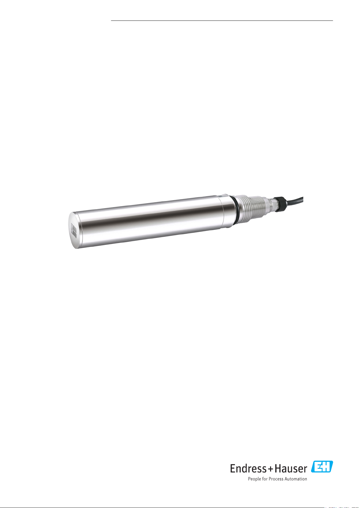
For turbidity measurement a light beam is directed through the medium and is deflected from its
original direction by optically denser particles, e.g. particles of solid matter. This process is also called
scattering.
A0030850
1 Deflection of light
1 Light source
2 Light beam
3 Particle
4 Scattered light
The incident light is scattered in many directions, i.e. at different angles to the direction of
propagation. 2 angle ranges are of particular interest here:
• Light scattered at a 90° angle is used primarily for turbidity measurement in drinking water.
• Light scattered at a 135° angle extends the dynamic range for high particle densities.
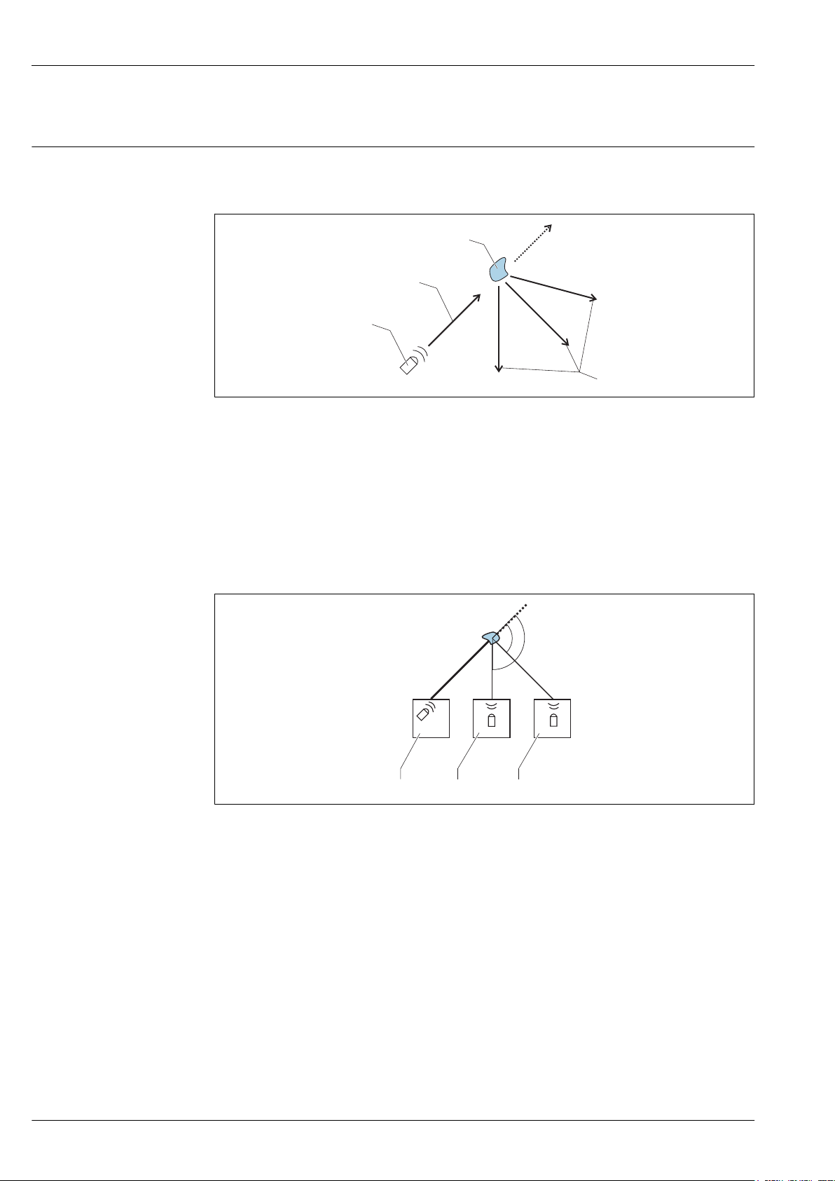
2 Principle mode of operation of turbidity sensor
1 Light source
2 135° light receiver
3 90° light receiver
If the particle density in the medium is low, a large amount of light is scattered in the 90°channel
and a small amount of light is scattered in the 135° channel. As the particle density increases, this
ratio shifts (more light in the 135° channel, less light in the 90° channel).
2 Endress+Hauser
A0030846
Page 3
Turbimax CUS51D
1
Ir
FNU
90°
135°
1
2
3
4
5
6
A0030849
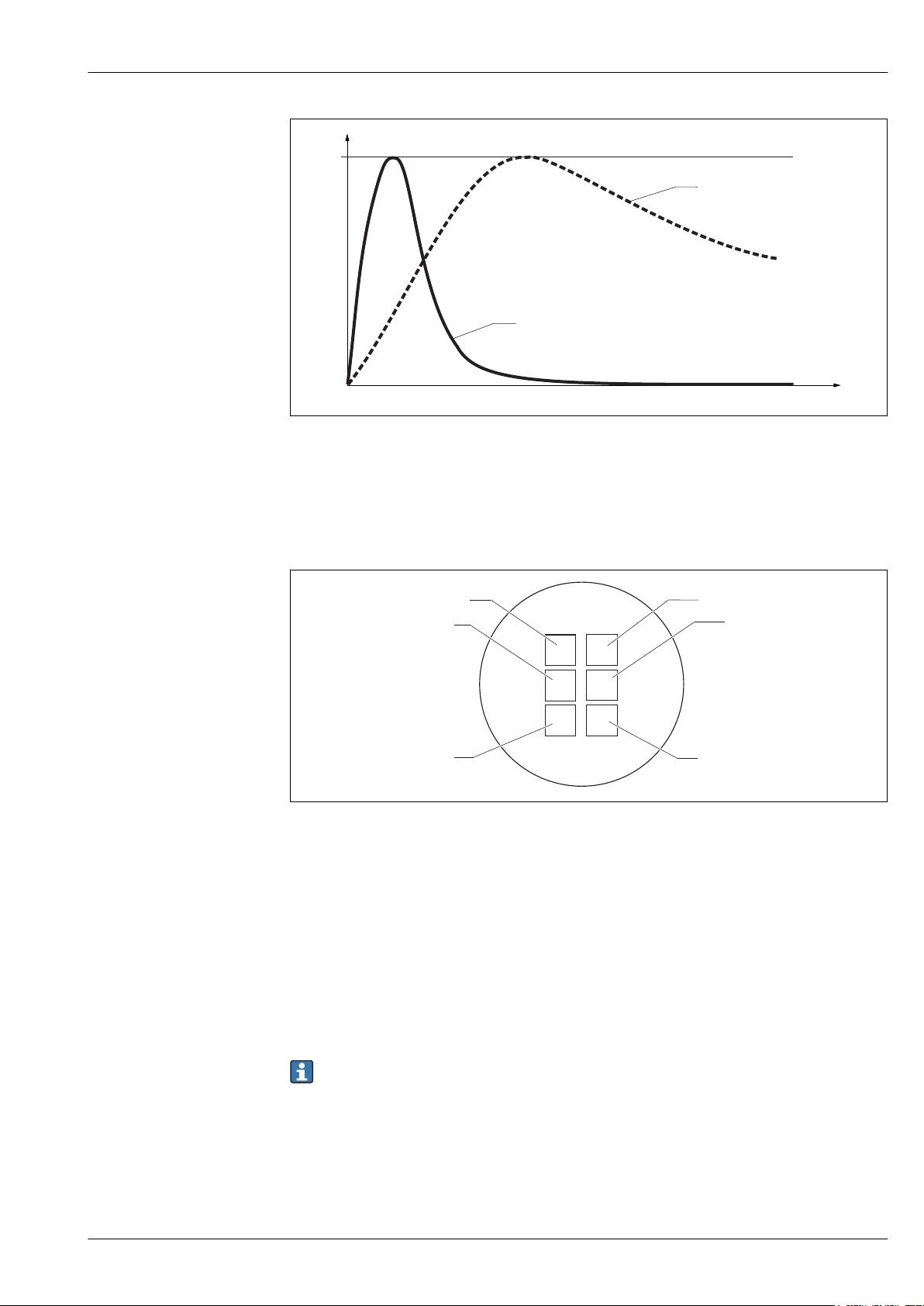
3 Signal distribution as a function of the particle density
Ir Relative intensity
FNU Turbidity unit
The CUS51D turbidity sensor has 2 sensor units, which are independent of each other and arranged
in parallel. The application-dependent evaluation of both signals leads to stable measured values.
A0030845
4 Arrangement of light sources and light receivers
1, 2 Light sources 1 and 2
3, 5 135° light receiver
4, 6 90° light receiver
The sensor covers a broad range of turbidity and solids measurements thanks to the optical
arrangement with 2 light sources, each with 2 light receivers placed at different angles (90° and
135°).
• As soon as the customer selects an application, e.g. activated sludge, the optical method best
suited for the particular measuring task is automatically activated in the sensor (e.g. 90°
measurements with both light sources).
• The double sensing system (2 light sources with 2 receivers per source) largely compensates for
measured errors caused by fouling (4-beam pulsed light method → 3).
The sensor types available vary in terms of their measuring ranges and therefore the range of
available applications.
Measuring methods
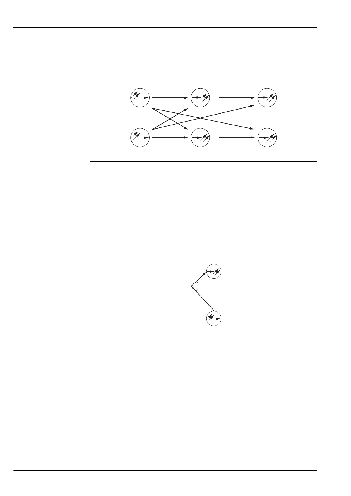
4-beam pulsed light method
The method is based on 2 light sources and 4 light receivers. Long-life LEDs are used as
monochromatic light sources. These LEDs are pulsed alternately and generate 4 scattered light
signals per LED pulse at the receivers.
Endress+Hauser 3
Page 4
Turbimax CUS51D
S
1
E
1-135
E
2-135
S
2
E
1-90
E
2-90
S
E
a
P
This offsets interference influences such as extraneous light, LED aging, fouling of windows and
absorption in the medium. Depending on the chosen application, different scattered light signals are
processed. The signal type, number and calculation are stored in the sensor.
A0030847
5 4-beam pulsed light method
S1 S
E
90
E
135
Light source
2
Light receiver for 90° scattered light
Light receiver for 135° scattered light
90° scattered light method
Measurement is performed with a wavelength of 860 Nm (634.3 lbf ft), as described in ISO 7027 /
EN 27027.
The emitted light beam is scattered by the solid particles in the medium. The scattered radiation
generated in this way is measured by scattered light receivers, which are arranged at an angle of 90°
to the light sources. The turbidity of the medium is determined by the amount of scattered light.
A0030852
6 90° scattered light method
S Light source
E Receiver
P Particle
135° backscattered light method
The emitted light beam is scattered by the solid particles in the medium. The backscattering
generated is measured by scattered light receivers, which are arranged next to the light sources. The
turbidity of the medium is determined based on the quantity of back-scattered light. It is possible to
measure very high turbidity values with this type of scattered light measurement.
4 Endress+Hauser
Page 5

Turbimax CUS51D
S
1
E
1
P
I
0
I
S
a
Is= I0· C · A· f(a)
A0030855
7 Principle of backscattered light method
IoIntensity of transmitted light
IsIntensity of scattered light
A Geometric factor
C Concentration
P Particle
f(α) Angle correlation
Sensor monitoring
The optical signals are continuously monitored and analyzed for plausibility. If inconsistencies occur,
an error message is output via the transmitter. The function is disabled by default.
In addition, the following fault states are detected in conjunction with the sensor check system of the
Liquiline M:
• Implausibly high or low measured values
• Disturbed regulation due to incorrect measured values
Applications
Fields of application
Application
(models)
Formazine Industrial water, WWTP outlet FNU / NTU
Kaolin Filterable matter, industrial water, WWTP outlet, low
SiO
2
TiO
2
Thin sludge Thin sludge, ranging from activated sludge to clear water g/l; ppm; %
Activated sludge Activated sludge basin and similar media g/l; ppm; % X
Waste activated
sludge
Univ. sludge Universal use ranging from clear water to sludge with a high
Digested sludge Contaminated sludge, black - homogeneous g/l; ppm; %
Fields of application/use Unit Compen
sation*
mg/l ; g/l;
concentrations of activated sludge
SiO2, mineral-based solids (sand) g/l; ppm; % X
TiO2, (white media) g/l; ppm; % X
Universal use for sludge in wastewater sector between 5 and
50 g/l (activated sludge, return activated sludge, ...)
concentration of solids, e.g. sludge extraction in thickeners. 0
g/l bis 50 g/l
ppm; %
g/l; ppm; % X
g/l; ppm; % X
* Contamination compensation with 4-beam pulsed light
NOTICE
Multiple scattering in the following applications: formazine, kaolin and thin sludge
If the specific operational range is exceeded, the measured value displayed by the sensor can
decrease despite increasing turbidity or increasing TS content. The indicated operational range is
Endress+Hauser 5
reduced in the case of highly absorbing (e.g. dark) media.
In the case of highly absorbing (e.g. dark) media, determine the operational range
‣
experimentally beforehand.
Page 6
Turbimax CUS51D
1
2
3
1
4
5
Measuring system
A complete measuring system comprises:
• Turbimax CUS51D turbidity sensor
• Liquiline CM44x multi-channel transmitter
• Assembly:
• Flexdip CYA112 assembly and Flexdip CYH112 holder or
• Retractable assembly, e.g. Cleanfit CUA451
A0030844
8 Measuring system with immersion assembly (example)
1 Flexdip CYH112 holder
2 Liquiline CM44x multi-channel transmitter
3 Protective cover
4 Flexdip CYA112 assembly
5 Turbimax CUS51D turbidity sensor
6 Endress+Hauser
Page 7

Turbimax CUS51D
2
3
5
4
3
4
2
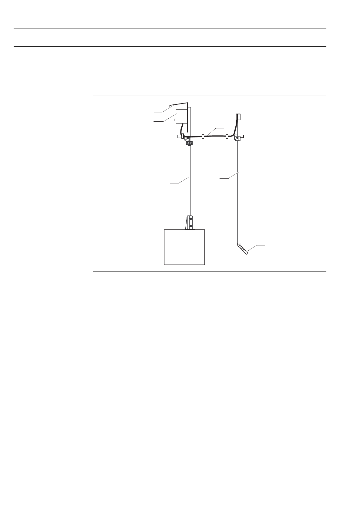
9 Measuring system with immersion assembly (example)
1 Liquiline CM44x multi-channel transmitter
2 Protective cover
3 Flexdip CYH112 holder
4 Flexdip CYA112 assembly
5 Turbimax CUS51D turbidity sensor
10 Measuring system with retractable assembly (example)
1 Turbimax CUS51D turbidity sensor
2 Liquiline CM44x multi-channel transmitter
3 Cleanfit CUA451 retractable assembly
4 Direction of flow
A0030856
A0030843
Endress+Hauser 7
Page 8

Turbimax CUS51D
1
4
5
6
Measured variable
Measuring range
11 Measuring system with immersion assembly on chain holder system
1 Flexdip CYH112 holder
2 Liquiline CM44x multi-channel transmitter
3 Protective cover
4 Chain of Flexdip CYH112 holder
5 Flexdip CYA112 assembly
6 Turbimax CUS51D turbidity sensor
Input
• Turbidity
• Solids content
• Temperature
CUS51D-**C1 Application
Turbidity 0,000 to 4000 FNU
Display range up to 9999 FNU
Solids content 0 to 5 g/l Kaolin, filterable matter
Temperature –20 to 80 °C (–4 to 176 °F)
Formazine
A0037077
8 Endress+Hauser
Page 9

Turbimax CUS51D
85 86
85
2DS
1
2
86
97 88 8798
97 88 8798
Sensor 1
Sensor 2
PK
GY
GN
YE
Sensor
85 86
85
1
2
86
97 88 8798
Sensor 1
PK
GY
GN
YE
BN
WH
Sensor
CUS51D-**D1 Application
Turbidity 0,000 to 4000 FNU
Formazine
Display range up to 9999 FNU
Solids content 0 to 300 g/l
Solids content depending on the selected application (see list)
0 to 30 %
Temperature –20 to 80 °C (–4 to 176 °F)
Measuring range with solids content:
For solids, the achievable ranges depend very much on the media that are actually present and
may differ from the recommended operating ranges. Extremely inhomogeneous media may
cause fluctuations in measured values, thus narrowing the measuring range.
Power supply
Electrical connection
The following connection options are available:
• via M12 connector (version: fixed cable, M12 connector)
• via sensor cable to the plug-in terminals of a sensor input on the transmitter (version: fixed cable,
end sleeves)
A0033092
12 Sensor connection to sensor input (left) or via M12 connector (right)
Endress+Hauser 9
Page 10

Connecting the cable shield
1
2
3
4
Cable sample (does not necessarily correspond to the original cable supplied)
Turbimax CUS51D
Reference operating conditions
Maximum measured error
Factory calibration
13 Terminated cable
1 Outer shield (exposed)
2 Cable cores with ferrules
3 Cable sheath (insulation)
14 Inserting the cable
4 Grounding clip
15 Tightening the screw
(2 Nm (1.5 lbf ft))
The cable shield is grounded by the
grounding clip
The maximum cable length is 100 m (328.1 ft).
Performance characteristics
20 °C (68 °F), 1013 hPa (15 psi)
Turbidity
Solids < 5% of the measured value or 1% of the upper range value (the greater value applies
The measured error encompasses all inaccuracies of the measuring chain (sensor and
transmitter). However, it does not include the inaccuracy of the reference material used for
calibration.
FNU and NTU in accordance with application table
Standard: 3 points
< 2% of measured value or 0.1 FNU (the greater value applies in each case).
in each case); applies to sensors that are calibrated for the observed measuring range.
Applications
The sensor has been calibrated in the factory for "formazine" applications. All other applications are
precalibrated with reference samples and require calibration to the corresponding application.
Calibration can be performed with up to 5 points.
Clear water application type Recommended operating ranges CUS51D
C1 D1
Application: Formazine 0 to 4000 FNU X X
Application: Kaolin 0 to 5 g/l X X
Application: SiO
Application: titanium dioxide 0.2 to 150 g/l X
2
5 to 100 g/l X
10 Endress+Hauser
Page 11

Turbimax CUS51D
0
5
10 15 20 25 30
35
40
45
505560 100 110 120 130 140 150 160
0
1000
9999
2000
3000
4000
5000
6000
7000
8000
9000
TiO2
Kaolin
Kieselguhr (SiO2)
Formazine
Turbidity (FNU)
0
5
10 15 20 25 30
35
40
45
50556080859095 100
Digested sludge
Excess sludge
Activated sludge
Thin sludge
Sludge univ.
A0030862-EN
Solids application type Recommended operating ranges CUS51D
C1 D1
Application: thin sludge 0 to 5 g/l X
Application: activated sludge 2 to 15 g/l X
Application: waste activated sludge 3 to 50 g/l X
Application: univ. sludge 0 to 50 g/l X
Digested sludge application 5 to 100 g/l / 300 g/l X
Drift
Detection limits
Installation instructions
Endress+Hauser 11
For solids, the achievable ranges depend very much on the media that are actually present and
may differ from the recommended operating ranges.
Working on the basis of electronic controls, the sensor is largely free of drifts.
Application Measuring range Detection limit
Formazine 0 to 50 FNU 0.006 FNU
0 to 4000 FNU 0.4 FNU
Kaolin 0 to 5000 mg/l 0.85 mg/l
Installation
Installation options:
• with Cleanfit W CUA451 retractable assembly
• with Flexdip CYA112 wastewater assembly and Flexdip CYH112 holder
• with Flowfit CYA251 flow assembly
A0038988-EN
Page 12

a
16 Installing with retractable assembly
1 Direction of flow
Turbimax CUS51D
Arrow 1 points in the direction of flow.
The installation angle α must not exceed 90°.
The recommended installation angle is 75°.
The optical windows in the sensor must be
aligned either parallel to the direction of flow
(α = 90°) or against the direction of flow
(α < 90°).
The medium pressure may not exceed
2 bar (29 psi) for manual assembly retraction.
A0031134
The arrow points in the direction of flow.
The installation angle is 45° (preferably) or
90°.
• If you are using the sensor in open basins,
install the sensor in such a way that air
bubbles cannot accumulate on it.
• If you are using the sensor in highly aerated
basins, install the sensor at an angle of 90°
to reduce the effects of air bubbles.
Pipes
A0037105
17 Installing with wastewater assembly
The installation angle is 90°.
For turbidity measurements < 200 FNU, the
backscattering of the internal surfaces of the
assembly causes distortions in the measured
values.
A0035858
18 Installing with CYA251 flow assembly
The following diagram shows different installation scenarios in pipes, indicating whether or not they
are permitted.
12 Endress+Hauser
Page 13

Turbimax CUS51D
4
5
2
2
1
3
3
A0030848
19 Orientations and positions (with CUA451 retractable assembly )
• When using reflective materials (e.g. stainless steel), the pipe diameter must be at least
100 mm (3.9 in). An onsite calibration is recommended.
• Install the sensor in places with consistent flow conditions.
• The best installation location is in the ascending pipe (item 1). Installation is also possible in the
horizontal pipe (item 5).
• Do not install in places where air spaces or bubbles occur (item 3) or where sedimentation may
occur (item 2).
• Avoid installation in the down pipe (item 4).
• When measuring turbidity < 200 FNU, the backscattering of the pipe wall causes distortions in the
measured values. For this reason, a multipoint calibration is recommended here.
• Avoid fittings downstream from pressure reduction stages which can lead to outgassing.
Ambient temperature range
Storage temperature
Degree of protection
Electromagnetic compatibility (EMC)
Process temperature range
Process pressure range
Minimum flow
Environment
–20 to 60 °C (–4 to 140 °F)
–20 to 70 °C (–4 to 158 °F)
IP 68 (1 m (3.3 ft) water column, 60 days, 1 mol/l KCl)
Interference emission and interference immunity as per
• EN 61326-1:2013
• EN 61326-2-3:2013
• NAMUR NE21: 2012
Process
–5 to 50 °C (23 to 122 °F)
Up to 80 °C (176 °F) for a short period of time (1 h)
0.5 to 10 bar (7.3 to 145 psi) (abs.)
No minimum flow required.
For solids which have a tendency to form deposits, ensure that sufficient mixing is performed.
Endress+Hauser 13
Page 14

Dimensions
Ø 40
(1.57)
NPT ¾“
G1
82.7 (3.26)
188.5 (7.42)
12.5 (0.49)
20.5
(0.81)
13.5 (0.53)
36
(1.42)
Turbimax CUS51D
Mechanical construction
Weight
Materials
Process connections
20 Dimensions. Dimensions: mm (in)
Dimensions for compressed air cleaning → 16
Approx. 0.7 kg (1.5 lb)without cable
Sensor
Optical windows Sapphire
O-rings EPDM
G1 and NPT ¾''
A0030853
Stainless steel 1.4404 (AISI 316 L)
Stainless steel 1.4571 (AISI 316 Ti)
14 Endress+Hauser
Page 15

Turbimax CUS51D
Accessories Compressed air cleaning
21 CUS51D with compressed air cleaning
Compressed air cleaning
Consumption: 50 l/min (13.2 gal/min)
Pressure: 1.5 to 2 bar (22 to 30 psi)
Connection: 6/8 mm or 6.35 mm (¼")
A0031105
mark
Electromagnetic compatibility
ISO 7027
EAC
Product page
Product Configurator
Certificates and approvals
The product meets the requirements of the harmonized European standards. As such, it complies
with the legal specifications of the EU directives. The manufacturer confirms successful testing of the
product by affixing to it the mark.
Interference emission and interference immunity as per
• EN 61326-1:2013
• EN 61326-2-3:2013
• NAMUR NE21: 2012
The measuring method used with the sensor complies with the ISO 7027-1:2016 standard.
The product has been certified according to guidelines TP TC 004/2011 and TP TC 020/2011 which
apply in the European Economic Area (EEA). The EAC conformity mark is affixed to the product.
Ordering information
www.endress.com/cus51d
On the product page there is a Configure button to the right of the product image.
1. Click this button.
The Configurator opens in a separate window.
2. Select all the options to configure the device in line with your requirements.
In this way, you receive a valid and complete order code for the device.
3. Export the order code as a PDF or Excel file. To do so, click the appropriate button on the right
above the selection window.
For many products you also have the option of downloading CAD or 2D drawings of the
selected product version. Click the CAD tab for this and select the desired file type using
picklists.
Scope of delivery
The delivery comprises:
• 1 Turbimax CUS51D sensor, version as ordered
• 1 Operating Instructions BA00461C
Endress+Hauser 15
Page 16

Turbimax CUS51D
Accessories
The following are the most important accessories available at the time this documentation was
issued.
For accessories not listed here, please contact your Service or Sales Center.
‣
Assemblies
Holder
FlowFit CUA120
• Flange adapter for mounting turbidity sensors CUS
• Product Configurator on the product page: www.endress.com/cua120
Technical Information TI096C
Flexdip CYA112
• Immersion assembly for water and wastewater
• Modular assembly system for sensors in open basins, channels and tanks
• Material: PVC or stainless steel
• Product Configurator on the product page: www.endress.com/cya112
Technical Information TI00432C
Cleanfit CUA451
• Manual retractable assembly made of stainless steel with ball valve shut-off for turbidity sensors
• Product Configurator on the product page: www.endress.com/cua451
Technical Information TI00369C
Flowfit CYA251
• Connection: See product structure
• Material: PVC-U
• Product Configurator on the product page: www.endress.com/cya251
Technical Information TI00495C
Flexdip CYH112
• Modular holder system for sensors and assemblies in open basins, channels and tanks
• For Flexdip CYA112 water and wastewater assemblies
• Can be affixed anywhere: on the ground, on the capstone, on the wall or directly onto railings.
• Plastic or stainless steel version
• Product Configurator on the product page: www.endress.com/cyh112
Technical Information TI00430C
Compressed air cleaning
Compressed air cleaning for CUS51D
• Connection: 6 mm (0.24 in) or 8 mm (0.31 in) (metric) or 6.35 mm (0.25 in)
• Materials: POM/V4A
• 6 or 8 mm order no.: 71110782
• 6.35 mm order no.: 71110783
16 Endress+Hauser
Page 17

Turbimax CUS51D
Ø 40.1
(1.58)
Ø 50 (1.97)
72 (2.83)
77.3 (3.04)
17.8
(0.70)
11.5
(0.45)
65.8 (2.59)
17.8
(0.70)
48 (1.89)
A
B
A0030854
22 Compressed air cleaning. Dimensions: mm (in)
A Version 6 mm (0.24 in)
B Version 6.35 mm (0.25 in)
Compressor
• For compressed air cleaning
• 230 V AC order no. 71072583
• 115 V AC order no. 71194623
Endress+Hauser 17
Page 18

Page 19

Page 20

www.addresses.endress.com
 Loading...