

Page 1
BA01281C/07/EN/03.19
71440423
2019-03-01
Products Solutions Services
Operating Instructions
Flowfit CUA252
Flow assembly for CUS52D turbidity sensor
Page 2

Page 3

Flowfit CUA252 Table of contents
Table of contents
1 About this document ................ 4
1.1 Warnings ............................ 4
1.2 Symbols used .......................... 4
2 Basic safety instructions ............ 5
2.1 Requirements for the personnel ............ 5
2.2 Designated use ........................ 5
2.3 Workplace safety ....................... 5
2.4 Operational safety ...................... 6
2.5 Product safety ......................... 6
3 Product description ................. 7
3.1 Product design ......................... 7
4 Incoming acceptance and product
identification ....................... 8
4.1 Incoming acceptance .................... 8
4.2 Product identification .................... 8
4.3 Scope of delivery ....................... 9
4.4 Certificates and approvals ................ 9
5 Installation ....................... 10
5.1 Mounting conditions ................... 10
5.2 Mounting the flow assembly ............. 12
5.3 Mounting the sensor ................... 15
5.4 Post-installation check .................. 15
6 Commissioning .................... 16
7 Maintenance ...................... 17
7.1 Maintenance tasks ..................... 17
7.2 Cleaning agent ....................... 18
8 Repair ............................ 19
8.1 Spare parts .......................... 19
8.2 Return .............................. 19
8.3 Disposal ............................ 19
9 Accessories ....................... 20
10 Technical data .................... 22
10.1 Environment ......................... 22
10.2 Process ............................. 22
10.3 Mechanical construction ................ 23
Index .................................. 25
Endress+Hauser 3
Page 4
About this document Flowfit CUA252
1 About this document
1.1 Warnings
Structure of information Meaning
DANGER
L
Causes (/consequences)
If necessary, Consequences of
non-compliance (if applicable)
Corrective action
‣
WARNING
L
Causes (/consequences)
If necessary, Consequences of
non-compliance (if applicable)
Corrective action
‣
CAUTION
L
Causes (/consequences)
If necessary, Consequences of
non-compliance (if applicable)
Corrective action
‣
NOTICE
Cause/situation
If necessary, Consequences of
non-compliance (if applicable)
Action/note
‣
This symbol alerts you to a dangerous situation.
Failure to avoid the dangerous situation will result in a fatal or serious
injury.
This symbol alerts you to a dangerous situation.
Failure to avoid the dangerous situation can result in a fatal or serious
injury.
This symbol alerts you to a dangerous situation.
Failure to avoid this situation can result in minor or more serious injuries.
This symbol alerts you to situations which may result in damage to
property.
1.2 Symbols used
Symbol Meaning
Additional information, tips
Permitted or recommended
Not permitted or not recommended
Reference to device documentation
Reference to page
Reference to graphic
Result of a step
1.2.1 Symbols on the device
Symbol Meaning
Reference to device documentation
4 Endress+Hauser
Page 5

Flowfit CUA252 Basic safety instructions
2 Basic safety instructions
2.1 Requirements for the personnel
• Installation, commissioning, operation and maintenance of the measuring system may
be carried out only by specially trained technical personnel.
• The technical personnel must be authorized by the plant operator to carry out the
specified activities.
• The electrical connection may be performed only by an electrical technician.
• The technical personnel must have read and understood these Operating Instructions
and must follow the instructions contained therein.
• Faults at the measuring point may only be rectified by authorized and specially trained
personnel.
Repairs not described in the Operating Instructions provided must be carried out only
directly at the manufacturer's site or by the service organization.
2.2 Designated use
The CUA252 flow assembly is designed for the installation of the CUS52D turbidity sensor.
Its mechanical construction means that it can be operated in pressurized systems (see
technical data→ 22).
The main areas of application are:
• Final turbidity measurement in outlet of waterworks
• Turbidity measurement in inlet of waterworks
• Turbidity measurement at all process stages
• Turbidity measurement for filter monitoring and filter backwashing
• Turbidity measurement in drinking water networks
The assembly is designed exclusively for use in liquid media.
Use of the device for any purpose other than that described, poses a threat to the safety of
people and of the entire measuring system and is therefore not permitted.
The manufacturer is not liable for damage caused by improper or non-designated use.
2.3 Workplace safety
As the user, you are responsible for complying with the following safety conditions:
• Installation guidelines
• Local standards and regulations
Endress+Hauser 5
Page 6

Basic safety instructions Flowfit CUA252
2.4 Operational safety
Before commissioning the entire measuring point:
1. Verify that all connections are correct.
2. Ensure that electrical cables and hose connections are undamaged.
3. Do not operate damaged products, and protect them against unintentional operation.
4. Label damaged products as defective.
During operation:
If faults cannot be rectified:
‣
products must be taken out of service and protected against unintentional operation.
2.5 Product safety
2.5.1 State of the art
The product is designed to meet state-of-the-art safety requirements, has been tested, and
left the factory in a condition in which it is safe to operate. The relevant regulations and
European standards have been observed.
6 Endress+Hauser
Page 7
Flowfit CUA252 Product description
1
2
3
4
3 Product description
3.1 Product design
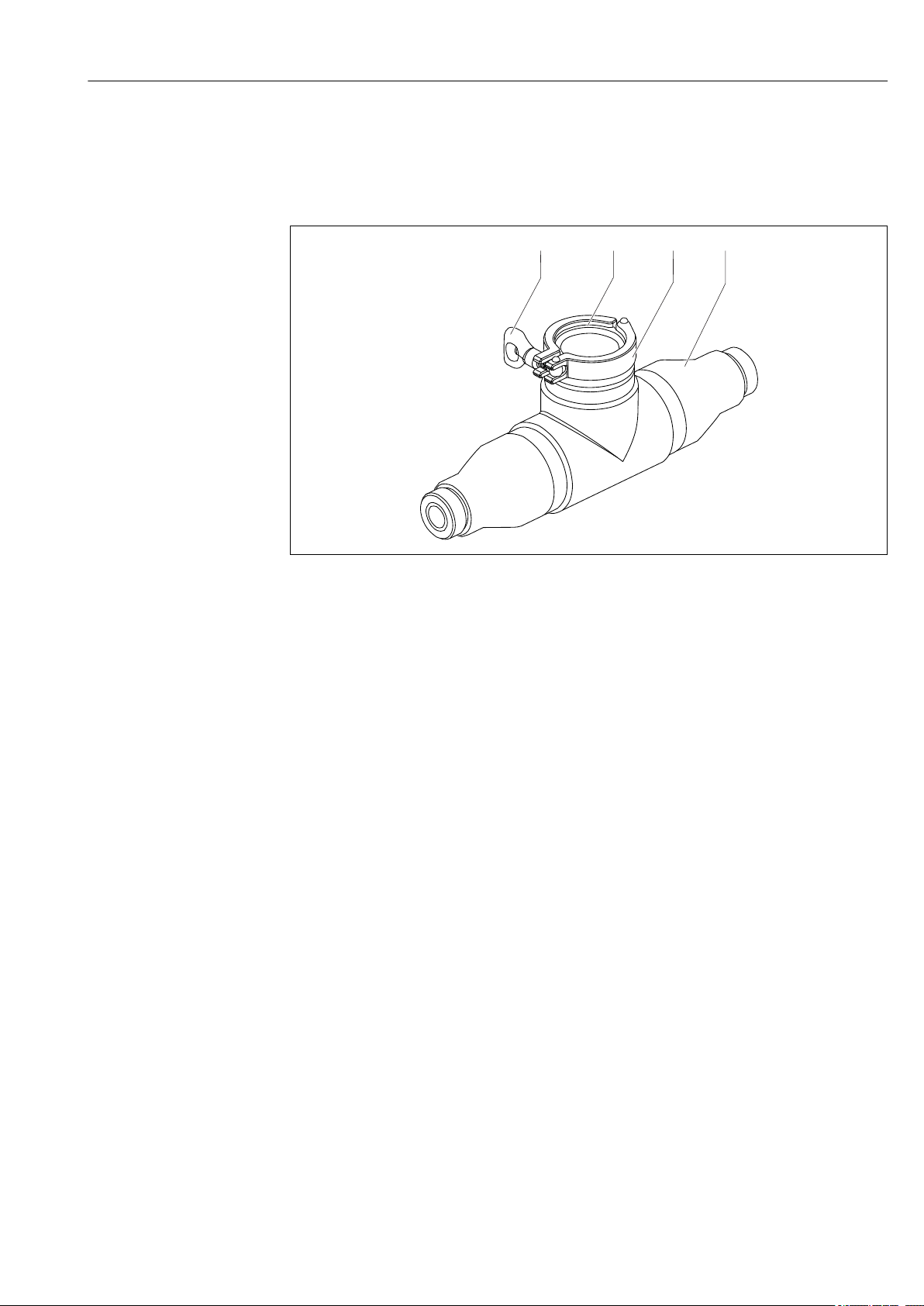
1 CUA252 flow assembly with locking clamp
1 Butterfly nut of locking clamp
2 Clamp seal
3 Locking clamp
4 Flow assembly CUA252
A0038827
Endress+Hauser 7
Page 8

Incoming acceptance and product identification Flowfit CUA252
4 Incoming acceptance and product
identification
4.1 Incoming acceptance
1. Verify that the packaging is undamaged.
Notify the supplier of any damage to the packaging.
Keep the damaged packaging until the issue has been resolved.
2. Verify that the contents are undamaged.
Notify the supplier of any damage to the delivery contents.
Keep the damaged goods until the issue has been resolved.
3. Check that the delivery is complete and nothing is missing.
Compare the shipping documents with your order.
4. Pack the product for storage and transportation in such a way that it is protected
against impact and moisture.
The original packaging offers the best protection.
Make sure to comply with the permitted ambient conditions.
If you have any questions, please contact your supplier or your local Sales Center.
4.2 Product identification
4.2.1 Nameplate
The nameplate provides you with the following information on your device:
• Manufacturer identification
• Order code
• Extended order code
• Serial number
• Ambient and process conditions
• Safety information and warnings
Compare the information on the nameplate with the order.
‣
4.2.2 Product identification
The order code and serial number of your product can be found in the following locations:
• On the nameplate
• In the delivery papers
Obtaining information on the product
1. Go to www.endress.com.
2. Call up the site search (magnifying glass).
3. Enter a valid serial number.
4. Search.
The product structure is displayed in a popup window.
5. Click on the product image in the popup window.
A new window (Device Viewer) opens. All of the information relating to your
device is displayed in this window as well as the product documentation.
8 Endress+Hauser
Page 9

Flowfit CUA252 Incoming acceptance and product identification
4.2.3 Manufacturer's address
Endress+Hauser Conducta GmbH+Co. KG
Dieselstraße 24
D-70839 Gerlingen
4.3 Scope of delivery
The scope of delivery comprises:
• 1 Flowfit CUA252 flow assembly, version as ordered
• 1 clamp seal and locking clamp
• 2 process connections, version as ordered
• 1 set of Operating Instructions
4.4 Certificates and approvals
DRGL- 2014/68/EU / PED- 2014/68/EU
The assembly has been manufactured according to good engineering practice as per Article
4, Paragraph 3 of the Pressure Equipment Directive 2014/68/EU and is therefore not
required to bear the CE label.
Endress+Hauser 9
Page 10

Installation Flowfit CUA252
5 Installation
5.1 Mounting conditions
5.1.1 Installation instructions
2 Connection example with open outlet
A0022259
10 Endress+Hauser
Page 11

Flowfit CUA252 Installation
p1
p2
p1 > p2
1
A0022258
3 Connection example with bypass and orifice plate in the main pipe (supply from below)
1 Orifice plate
No measures to increase pressure are required for branch pipes (pipes that branch off
from the main pipe).
To achieve flow through the assembly with a bypass, pressure p1 must be higher than
pressure p2.
Install the orifice plate in the main pipe → 3, 11.
‣
The inlet and outlet connection of the flow assembly are always identical. The system is
symmetrical.
1. Install the flow assembly vertically.
2. Connect the inflow at the bottom end (upward flow in the pipe).
Avoid buckles and loops in the hose system.
Pay attention to the installation instructions (flow direction) for the sensor.
Many media tend to develop gas bubbles in a depressurized state. The operation of the
flow assembly under pressure (adjustable valve after the flow assembly) prevents this
behavior in many cases.
Endress+Hauser 11
Page 12

Installation Flowfit CUA252
7
1
2
3
4
5
6
5.2 Mounting the flow assembly
5.2.1 Measuring system
A complete measuring system comprises:
• Flow assembly Flowfit CUA252
• Sensor Turbimax CUS52D
• Transmitter, e.g. Liquiline CM442
• Measuring cable
4 Measuring system
1 Process pipe
2 Measuring cable
3 Liquiline CM442 transmitter
4 Return line with shut-off valve
5 Turbidity sensor CUS52D
6 Flow assembly CUA252
7 Inlet with shut-off valve
12 Endress+Hauser
A0022262
Page 13

Flowfit CUA252 Installation
291 (11.46)
1
5.2.2 Mounting the assembly with wall holder unit
A0022264
5 Wall holder unit. Engineering unit: mm (in)
1 Hanger bolt STST 10x60 (included in scope of delivery of wall mounting kit)
Mounting the flow assembly in a bypass
1. Install a shut-off valve upstream and downstream from the flow assembly in the
bypass line.
This makes it possible to perform maintenance tasks,
such as the cleaning of the sensor, without affecting the process.
2. Mount the assembly vertically.
3. Establish the medium connection using commercially available connection fittings.
Mounting the flow assembly in a branch pipe with an open outlet
1. Install a shut-off valve upstream from the flow assembly.
2. Mount the assembly vertically.
3. Establish the medium connection using commercially available connection fittings.
Endress+Hauser 13
Page 14

Installation Flowfit CUA252
1
2
3
4
5
6
7
8
9
10
5.2.3 Mounting the assembly with a bubble trap
A0035917
6 Connection example with bubble trap
1 Inlet from below
2 Shutoff valve
3 Bubble trap
4 Venting of bubble trap (included in scope of delivery)
5 Shut-off valve (throttle for increasing pressure)
6 Outlet
7 D 12 adapter with connection for vent pipe (included in scope of delivery)
8 Flow assembly CUA252
9 Turbidity sensor CUS52D
10 D 12 adapter
The wastewater from the bubble trap is not suitable for feeding back into the process.
1. For the hose system, use PVC hoses with an internal diameter of 12 mm (0.5 in).
2. Secure the hose system using worm drive hose clips (not included in scope of
delivery).
The inlet and outlet connection of the flow assembly are always identical. The system is
symmetrical.
Mounting the flow assembly
1. Install the flow assembly vertically. The inflow must be connected at the bottom end
(upward flow in the pipe).
14 Endress+Hauser
Page 15

Flowfit CUA252 Installation
10
11
12
13
1
2
3
2. Insert an orifice plate into the upper assembly connection to obtain the desired
volume flow (included in the delivery).
Orifice plates:
• 1 mm (0.04 in) for volume flow < 60 l/h (15.8 gal/h)
• 3 mm (0.12 in) for volume flow 60 to 100 l/h (15.8 to 26.4 gal/h)
• 5 mm (0.2 in) for volume flow > 100 l/h (26.4 gal/h)
Avoid buckles and loops in the hose system.
Pay attention to the installation instructions (flow direction) for the sensor → 10.
Note the maximum pressure and maximum temperature when operating the bubble
trap → 22.
5.3 Mounting the sensor
A0035919
8 Sensor orientation
A0035918
7 Sensor installation
10 Flow assembly CUA252
11 Clamp seal
12 Locking clamp
13 Turbidity sensor CUS52D
1 Optical windows
2 Direction of flow
3 Installation marking
Only insert turbidity sensors into the assembly with a 2" clamp.
1. Install the sensor in such a way that the optical windows of the sensor are aligned
against the direction of flow (item 2).
2. Use the installation marking (item 3) on the sensor to ensure the correct sensor
orientation.
5.4 Post-installation check
• After mounting, check all the connections to ensure they are secure and leak-tight.
• Make sure that the orientation is correct.
• Ensure that the hoses cannot be removed without force.
• Check all hoses for damage.
Endress+Hauser 15
Page 16

Commissioning Flowfit CUA252
6 Commissioning
Prior to initial commissioning, ensure that:
• all seals are correctly seated (on the assembly and on the process connection).
• the sensor is correctly installed and connected.
WARNING
L
Medium incorrectly connected to the assembly
Medium can escape!
Before applying pressure to an assembly, ensure that the connection has been
‣
established correctly. Otherwise, do not introduce the assembly into the process.
16 Endress+Hauser
Page 17

Flowfit CUA252 Maintenance
1
2
2
7 Maintenance
Perform maintenance tasks at regular intervals.
‣
We recommend setting the maintenance times in advance in an operations journal or
log.
The maintenance cycle primarily depends on the following:
• The system
• The mounting conditions
• The medium in which measurement takes place
CAUTION
L
Escaping medium
Risk of injury to skin and eyes!
Before the maintenance task, ensure that the process pipe is unpressurized, empty and
‣
rinsed.
Wear protective gloves, protective goggles and protective clothing.
‣
7.1 Maintenance tasks
7.1.1 Cleaning the assembly
• Remove light dirt and fouling with suitable cleaning solutions. Cleaning agent → 18
• Remove heavy soiling using a soft brush and a suitable cleaning agent.
• For very persistent dirt, immerse the parts in a cleaning solution. Then clean the parts
with a brush.
A typical cleaning interval for drinking water, for example, is 6 months.
7.1.2 Checking and replacing the seals
1. Inspect seals at regular intervals.
2. Replace seals if necessary.
A0035921
9 Position of seals
1 Clamp seal
2 O-rings
The seals are available as a spare parts kit.
Endress+Hauser 17
Page 18

Maintenance Flowfit CUA252
7.2 Cleaning agent
WARNING
L
Organic solvents containing halogens
Limited evidence of carcinogenicity! Dangerous for the environment with long-term
effects!
Do not use organic solvents that contain halogens.
‣
WARNING
L
Thiocarbamide
Harmful if swallowed! Limited evidence of carcinogenicity! Possible risk of harm to the
unborn child! Dangerous for the environment with long-term effects!
Wear protective goggles, protective gloves and appropriate protective clothing.
‣
Avoid all contact with the eyes, mouth and skin.
‣
Avoid discharge into the environment.
‣
The most common types of soiling and the cleaning agents used in each case are shown in
the following table.
Type of soiling Cleaning agent
Greases and oils Hot water or tempered (alkaline) agents containing
surfactants or water-soluble organic solvents (e. g.
ethanol)
Limescale deposits, metal
hydroxide buildup, lyophobic
biological buildup
Sulfide deposits Mixture of 3% hydrochloric acid and thiocarbamide
Protein buildup Mixture of 3% hydrochloric acid and pepsin
Fibers, suspended substances Pressurized water, possibly surface-active agents
Light biological buildup Pressurized water
Choose a cleaning agent to suit the degree and type of soiling.
‣
Approx. 3% hydrochloric acid
(commercially available)
(commercially available)
18 Endress+Hauser
Page 19

Flowfit CUA252 Repair
8 Repair
8.1 Spare parts
Order number Description
71241882 Clamp seal, DN 50, FDA, 2 pcs
71241892 O-rings, EPDM, 2 sets
8.2 Return
The product must be returned if repairs or a factory calibration are required, or if the
wrong product was ordered or delivered. As an ISO-certified company and also due to legal
regulations, Endress+Hauser is obliged to follow certain procedures when handling any
returned products that have been in contact with medium.
To ensure the swift, safe and professional return of the device:
Refer to the website www.endress.com/support/return-material for information on the
‣
procedure and conditions for returning devices.
8.3 Disposal
Please observe local regulations!
‣
Endress+Hauser 19
Page 20

Accessories Flowfit CUA252
254 (10.0)
12 (0.5)
12 (0.5)
1
2
3
9 Accessories
The following are the most important accessories available at the time this documentation
was issued.
For accessories not listed here, please contact your Service or Sales Center.
‣
Description Order number
Dummy cover for clamp connection; 1 pc 71242180
Adapter, internal thread, RP ¾", material: PE; 1 pc 71242172
Adapter, internal thread, NPT ¾", material: PE; 1 pc 71242173
Adapter, welded connection, D 25, material: PE; 1 pc 71242174
Adapter, hose connection nipple, D 25, material: PE; 1 pc 71242175
Adapter, hose connection nipple, D 12, material: PE; 1 pc 71242176
Adapter, flange ANSI 2", 1 pc 71242177
Ultrasonic cleaning system CYR52
• For attachment to assemblies and pipes
• Product Configurator on the product page: www.endress.com/cyr52
Technical Information TI01153C
Bubble trap
• For the CUS52D sensor
• Process pressure: up to 3 bar (43.5 psi)
• Process temperature: 0 to 50 °C (32 to 122 °F)
• D 12 adapter with connection for degassing line (upper connection on the CUA252) is
included in the scope of delivery.
• Orifice plates for the following volume flows:
• < 60 l/h (15.8 gal/h)
• 60 to 100 l/h (15.8 to 26.4 gal/h)
• > 100 l/h (26.4 gal/h)
• The degassing line is fitted with a PVC hose, backpressure hose valve and luer lock
adapter.
• Order number, suitable for CUA252 assembly: 71242170
10 Bubble trap. Engineering unit: mm (in)
1 Inlet for medium (without hose system)
2 Outlet for bubbles (hose system is included in scope of delivery)
3 Outlet for medium (without hose system)
Wall mounting kit for CUA252
Order number: 71242171
20 Endress+Hauser
A0035757
Page 21

Flowfit CUA252 Accessories
291 (11.46)
1
A0022264
11 Wall mounting kit. Engineering unit: mm (in)
1 Hanger bolt STST 10 x 60 mm (included in scope of delivery)
Endress+Hauser 21
Page 22

Technical data Flowfit CUA252
p [bar]
T[°C]
10 4030
4
20
T[°F]
p [psi]
58
0
32
0
0
6
87
50 60
50
68 86
104
122
140
p [bar]
T[°C]
10 4030
3
20
T[°F]
p [psi]
43,5
0
32
0
0
50
50
68 86
104
122
10 Technical data
10.1 Environment
Ambient temperature
0 to 55 °C (32 to 131 °F)
range
Storage temperature 0 to 60 °C (32 to 140 °F), in the original packaging
10.2 Process
Process temperature range 0 to 60 °C (32 to 140 °F)
Process pressure range 0 to 6 bar (0 to 87 psi)
0 to 3 bar (0 to 43.5 psi)
Pressure/temperature ratings
12 Pressure/temperature ratings
13 Pressure/temperature ratings for bubble trap
22 Endress+Hauser
A0035922
A0039233
Page 23

Flowfit CUA252 Technical data
X X
Y
Y
105
(4.13)
50
(1.97)
Ø 81.5
(3.21)
124
(4.88)
197 (7.76)
350 (13.78)
Ø 75
(2.95)
Ø 50 (1.97)
Ø 81.5
(3.21)
Flow velocity Max. 2 m/s (6.6 ft/s) for low-viscosity media in pipes NW 50
Flow limit
Recommended flow: 60 l/h (15.8 gal/h)
Range: 10 to 100 l/h (2.64 to 26.4 gal/h)
If operating with lost sample (water loss)
Pressure loss < 0.05 bar (0.7 psi) for flow up to 100 l/h (26.4 gal/h)
10.3 Mechanical construction
Dimensions
A0022255
14 Dimensions. Engineering unit: mm (in)
Connections NPT ¾" Rp ¾ Glue-in port D25ANSI 2" Hose D 25 Hose D 12 G1 ¾
X mm (in) 70 (2.76) 64 (2.52) 22 (0.87) 71 (2.80) 74 (2.91) 74 (2.91) 0
Y mm (in) Ø 58(2.28) Ø 58(2.28) Ø 58(2.28) Ø 152
(5.98)
Ø 58(2.28) Ø 58(2.28) Ø 58(2.28)
Weight 1.17 kg (2.58 lb) without process connection
Materials
Assembly housing: PE100
Seals: EPDM
Flange: PP-GF
Dummy cover: Stainless steel 1.4404 (AISI 316 L)
Endress+Hauser 23
Page 24

Technical data Flowfit CUA252
B2
B3
C1
D1
E2
Bubble trap: Polycarbonate
Process connections: PE
Process connection for bubble trap: PVC
Process connections
A0035923
15 Process connections
B2 Internal thread Rp ¾"
B3 Internal thread NPT ¾"
C1 Glue-in port D 25
D1 Hose D 25
E2 Flange ANSI 2"
It is also possible to use an external thread G1 ¼ (standard) or a D 12 hose.
24 Endress+Hauser
Page 25

Flowfit CUA252 Index
Index
A
Approvals .................................. 9
C
Certificates ................................. 9
D
Designated use .............................. 5
I
Incoming acceptance .......................... 8
N
Nameplate ................................. 8
P
Product identification ......................... 8
S
Safety instructions ............................5
Symbols ................................... 4
U
Use .......................................5
W
Warnings .................................. 4
Endress+Hauser 25
Page 26

Page 27

Page 28

*71440423*
71440423
www.addresses.endress.com
 Loading...