

Page 1
BA00465C/07/EN/24.20
71473511
2020-03-19
Valid as of version
01.07.00
Products Solutions Services
Operating Instructions
Liquiport CSP44
Portable sampler for liquid media
Page 2

Page 3

Liquiport CSP44 Table of contents
Table of contents
1 About this document ................ 5
1.1 Warnings ............................ 5
1.2 Symbols .............................. 5
1.3 Symbols on the device ................... 5
1.4 Documentation ........................ 6
2 Basic safety instructions ............ 7
2.1 Requirements for personnel ............... 7
2.2 Designated use ........................ 7
2.3 Workplace safety ....................... 7
2.4 Operational safety ...................... 8
2.5 Product safety ......................... 9
3 Product description ................ 10
3.1 Device design ......................... 10
3.2 Terminal diagram ..................... 11
4 Incoming acceptance and product
identification ..................... 12
4.1 Incoming acceptance ................... 12
4.2 Product identification ................... 12
4.3 Scope of delivery ...................... 12
4.4 Certificates and approvals ............... 13
5 Installation ....................... 14
5.1 Installation conditions .................. 14
5.2 Installation .......................... 16
5.3 Connecting the suction line .............. 16
5.4 Post-installation check .................. 16
6 Electrical connection .............. 17
6.1 Connecting the sampler ................. 17
6.2 Connecting modules and sensors .......... 19
6.3 Terminal assignment for input/output
signals .............................. 19
6.4 Signal cable connection (optional) ......... 20
6.5 Ensuring the degree of protection .......... 21
6.6 Post-connection check .................. 22
7 System integration ................ 23
7.1 Service interface ...................... 23
8 Operation options ................. 24
8.1 Overview ............................ 24
8.2 Access to the operating menu via the local
display ............................. 25
8.3 Configuration options .................. 26
9 Commissioning .................... 29
9.1 Function check ....................... 29
9.2 Switching on the measuring device ......... 29
9.3 Setting the operating language ............ 30
9.4 Configuring the measuring device .......... 30
10 Operation ......................... 35
10.1 Display ............................. 35
10.2 General settings ....................... 36
10.3 Programming ........................ 47
10.4 Inputs .............................. 81
10.5 Outputs ............................. 86
11 Diagnostics and troubleshooting ... 94
11.1 General troubleshooting ................. 94
11.2 Diagnostic information on local display ...... 95
11.3 Adapting the diagnostic information ....... 95
11.4 Overview of diagnostic information ........ 97
11.5 Pending diagnostic messages ............ 104
11.6 Diagnosis list ........................ 104
11.7 Logbooks ........................... 104
11.8 Device information ................... 110
11.9 Simulation .......................... 111
11.10 Device test .......................... 113
11.11 Resetting the measuring device .......... 115
11.12 Information on operating times .......... 115
11.13 Status of inputs/outputs ................ 115
11.14 Firmware history ..................... 116
12 Maintenance .................... 120
12.1 Recommended maintenance ............ 120
12.2 Calibration ......................... 121
12.3 Replacing the pump tube ............... 122
12.4 Cleaning ........................... 124
12.5 Replacing the rechargeable batteries ...... 126
12.6 Technical support .................... 127
13 Repair ........................... 128
13.1 Spare parts ......................... 128
13.2 Return ............................. 129
13.3 Disposal ........................... 129
14 Accessories ...................... 130
14.1 Measuring cable ..................... 131
14.2 Sensors ............................ 131
15 Technical data ................... 136
15.1 Input .............................. 136
15.2 Binary input, passive (optional) .......... 136
15.3 Temperature inputs (optional) ........... 136
15.4 Analog input, passive/active (optional) ..... 136
Endress+Hauser 3
Page 4

Table of contents Liquiport CSP44
15.5 Output optional ...................... 136
15.6 Power supply ........................ 137
15.7 Performance characteristics ............. 137
15.8 Environment ........................ 138
15.9 Process ............................ 138
15.10 Mechanical construction ............... 139
Index ................................. 141
4 Endress+Hauser
Page 5
Liquiport CSP44 About this document
1 About this document
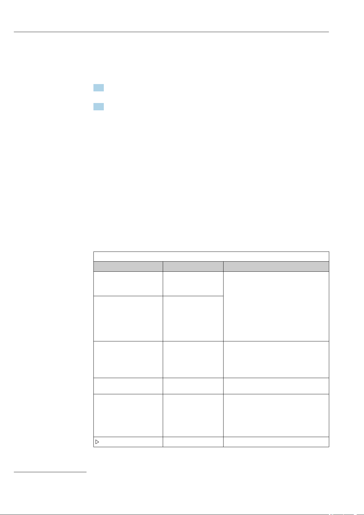
1.1 Warnings
Structure of information Meaning
DANGER
L
Causes (/consequences)
If necessary, Consequences of
non-compliance (if applicable)
Corrective action
‣
WARNING
L
Causes (/consequences)
If necessary, Consequences of
non-compliance (if applicable)
Corrective action
‣
CAUTION
L
Causes (/consequences)
If necessary, Consequences of
non-compliance (if applicable)
Corrective action
‣
NOTICE
Cause/situation
If necessary, Consequences of
non-compliance (if applicable)
Action/note
‣
This symbol alerts you to a dangerous situation.
Failure to avoid the dangerous situation will result in a fatal or serious
injury.
This symbol alerts you to a dangerous situation.
Failure to avoid the dangerous situation can result in a fatal or serious
injury.
This symbol alerts you to a dangerous situation.
Failure to avoid this situation can result in minor or more serious injuries.
This symbol alerts you to situations which may result in damage to
property.
1.2 Symbols
Symbol Meaning
Additional information, tips
Permitted or recommended
Not permitted or not recommended
Reference to device documentation
Reference to page
Reference to graphic
Result of a step
1.3 Symbols on the device
Symbol Meaning
Reference to device documentation
Endress+Hauser 5
Page 6

About this document Liquiport CSP44
1.4 Documentation
The following manuals which are available on the complement these Brief Operating
Instructions Operating Instructions:
• Brief Operating Instructions for Liquiport CSP44, BA00465C
• Operating Instructions for Memosens, BA01245C
• Software description for Memosens inputs
• Calibration of Memosens sensors
• Sensor-specific diagnostics and troubleshooting
• Guidelines for communication via fieldbus and web server
• Special Documentation: Sampler application manual SD01068C
• Documentation on other devices in the Liquiline platform:
• Liquiline CM44xR (DIN rail device)
• Liquiline System CA80 (analyzer)
• Liquiline System CAT8x0 (sample preparation)
• Liquistation CSFxx (sampler)
• Liquiport CSP44 (sampler)
6 Endress+Hauser
Page 7

Liquiport CSP44 Basic safety instructions
2 Basic safety instructions
2.1 Requirements for personnel
• Installation, commissioning, operation and maintenance of the measuring system may
be carried out only by specially trained technical personnel.
• The technical personnel must be authorized by the plant operator to carry out the
specified activities.
• The electrical connection may be performed only by an electrical technician.
• The technical personnel must have read and understood these Operating Instructions
and must follow the instructions contained therein.
• Faults at the measuring point may only be rectified by authorized and specially trained
personnel.
Repairs not described in the Operating Instructions provided must be carried out only
directly at the manufacturer's site or by the service organization.
2.2 Designated use
Liquiport 2010 CSP44 is a portable sampler for liquid media in non-hazardous areas. The
samples are taken discontinuously using a peristaltic pump and are then distributed into
sampling containers.
The sampler is designed for use in the following applications:
• Communal and industrial wastewater treatment plants
• Laboratories and water management offices
• Monitoring of liquid media in industrial processes
Use of the device for any purpose other than that described, poses a threat to the safety of
people and of the entire measuring system and is therefore not permitted. The
manufacturer is not liable for damage caused by improper or non-designated use.
2.3 Workplace safety
As the user, you are responsible for complying with the following safety conditions:
• Installation guidelines
• Local standards and regulations
• Regulations for explosion protection
Electromagnetic compatibility
• The product has been tested for electromagnetic compatibility in accordance with the
applicable international standards for industrial applications.
• The electromagnetic compatibility indicated applies only to a product that has been
connected in accordance with these Operating Instructions.
Endress+Hauser 7
Page 8

Basic safety instructions Liquiport CSP44
2.4 Operational safety
Before commissioning the entire measuring point:
1. Verify that all connections are correct.
2. Ensure that electrical cables and hose connections are undamaged.
3. Do not operate damaged products, and protect them against unintentional operation.
4. Label damaged products as defective.
During operation:
If faults cannot be rectified:
‣
products must be taken out of service and protected against unintentional operation.
8 Endress+Hauser
Page 9

Liquiport CSP44 Basic safety instructions
2.5 Product safety
2.5.1 State of the art
The product is designed to meet state-of-the-art safety requirements, has been tested, and
left the factory in a condition in which it is safe to operate. The relevant regulations and
international standards have been observed.
Devices connected to the sampler must comply with the applicable safety standards.
2.5.2 IT security
We only provide a warranty if the device is installed and used as described in the
Operating Instructions. The device is equipped with security mechanisms to protect it
against any inadvertent changes to the device settings.
IT security measures in line with operators' security standards and designed to provide
additional protection for the device and device data transfer must be implemented by the
operators themselves.
Endress+Hauser 9
Page 10
Product description Liquiport CSP44
1
2
3
4
5
6
7
8
9
10
11
12
13
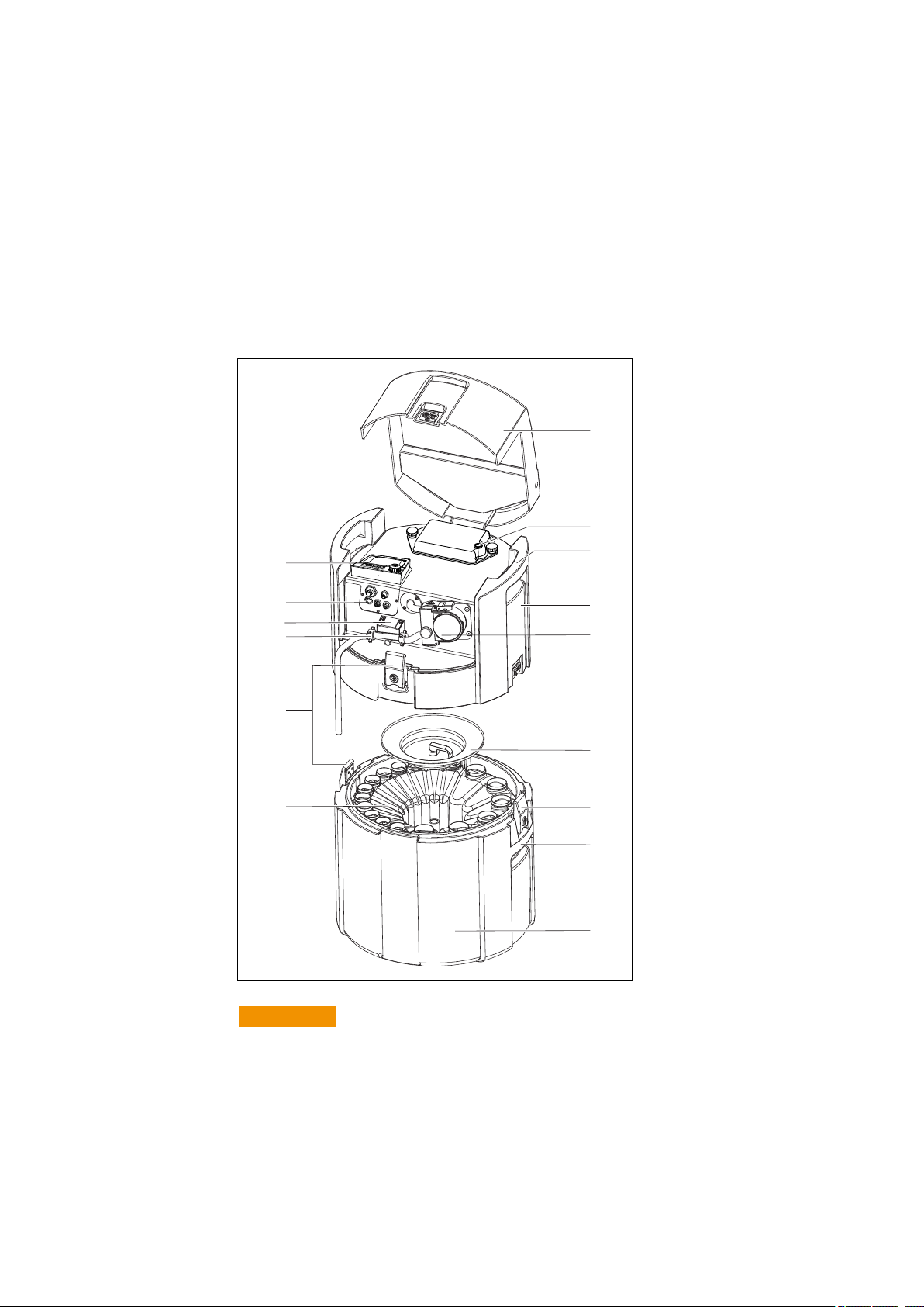
3 Product description
3.1 Device design
A complete sampling unit comprises:
• Controller with display, soft keys and navigator
• Vacuum or peristaltic pump for sampling
• PE or glass sample bottles for sample preservation
• Sampling chamber temperature regulator (optional) for safe sample storage
• Suction line with suction head
1 Device cover
2 Battery compartment cover
with switch
3 Upper carrying handles
4 Unit upper compartment
5 Peristaltic pump with pump
tubing
6 Bottle retaining cover
7 Lockable latches
8 Lower carrying handles
9 Unit lower compartment
10 Bottle distribution
11 Lockable latches
12 Hose connection
13 Medium detection
14 Electrical connections
15 Controller
WARNING
L
A0013533
Risk of injury
Danger of injury due to rotating parts
Secure the sampler against unintentional start-up whilst you work on the opened hose
‣
pump.
10 Endress+Hauser
Page 11

Liquiport CSP44 Product description
3.2 Terminal diagram
The unique terminal name is derived from:
Slot no. : Port no. : Terminal
Example, NO contact of a relay
Device with inputs for digital sensors, 4 current outputs and 4 relays
• Base module BASE2-E (contains 2 sensor inputs, 2 current outputs)
• 2AO module (2 current outputs)
• 4R module (4 relays)
Endress+Hauser 11
Page 12

Incoming acceptance and product identification Liquiport CSP44
4 Incoming acceptance and product
identification
4.1 Incoming acceptance
1. Verify that the packaging is undamaged.
Notify the supplier of any damage to the packaging.
Keep the damaged packaging until the issue has been resolved.
2. Verify that the contents are undamaged.
Notify the supplier of any damage to the delivery contents.
Keep the damaged goods until the issue has been resolved.
3. Check that the delivery is complete and nothing is missing.
Compare the shipping documents with your order.
4. Pack the product for storage and transportation in such a way that it is protected
against impact and moisture.
The original packaging offers the best protection.
Make sure to comply with the permitted ambient conditions.
If you have any questions, please contact your supplier or your local Sales Center.
4.2 Product identification
Nameplates can be found:
• On the inside of the door
• On the packaging (adhesive label, portrait format)
• On the inside of the device cover
4.2.1 Nameplate
The nameplate provides you with the following information on your device:
• Manufacturer identification
• Order code
• Extended order code
• Serial number
• Firmware version
• Ambient and process conditions
• Input and output values
• Activation codes
• Safety information and warnings
• Certificate information
Compare the information on the nameplate with the order.
‣
4.3 Scope of delivery
The scope of delivery comprises:
• 1 Liquiport 2010 CSP44 with:
• The ordered bottle configuration
• Optional hardware
• 1 print version of Brief Operating Instructions in the language ordered
• Optional accessories
If you have any queries:
‣
Please contact your supplier or local sales center.
12 Endress+Hauser
Page 13

Liquiport CSP44 Incoming acceptance and product identification
4.4 Certificates and approvals
4.4.1
Declaration of Conformity
The product meets the requirements of the harmonized European standards. As such, it
complies with the legal specifications of the EU directives. The manufacturer confirms
successful testing of the product by affixing to it the mark.
MCERTS
The device has been assessed by Sira Certification Service and complies with "MCERTS
Performance Standards for Water Monitoring Equipment Part 1, Version 2.1 dated
November 2009"; certificate no.: Sira MC100176/02.
EAC
The product has been certified according to guidelines TP TC 004/2011 and TP TC
020/2011 which apply in the European Economic Area (EEA). The EAC conformity mark
is affixed to the product.
mark
Endress+Hauser 13
Page 14
Installation Liquiport CSP44
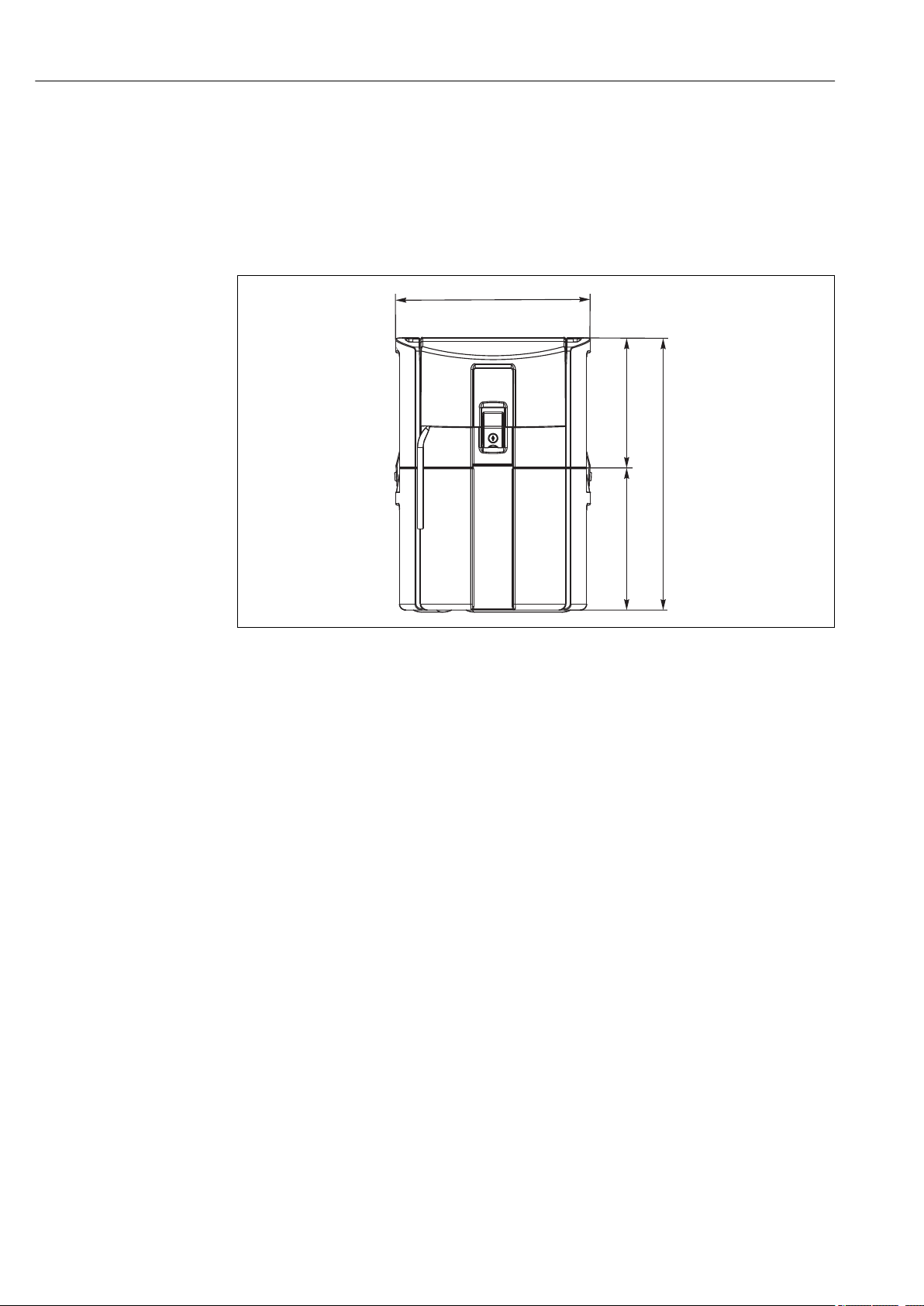
480 (18.9)
675 (26.6)
320 (12.6)
355 (14.0)
5 Installation
5.1 Installation conditions
5.1.1 Dimensions
A0013473
1 CSP44 standard version, dimensions in mm (in)
14 Endress+Hauser
Page 15
Liquiport CSP44 Installation
5.1.2 Installation site
A0013474
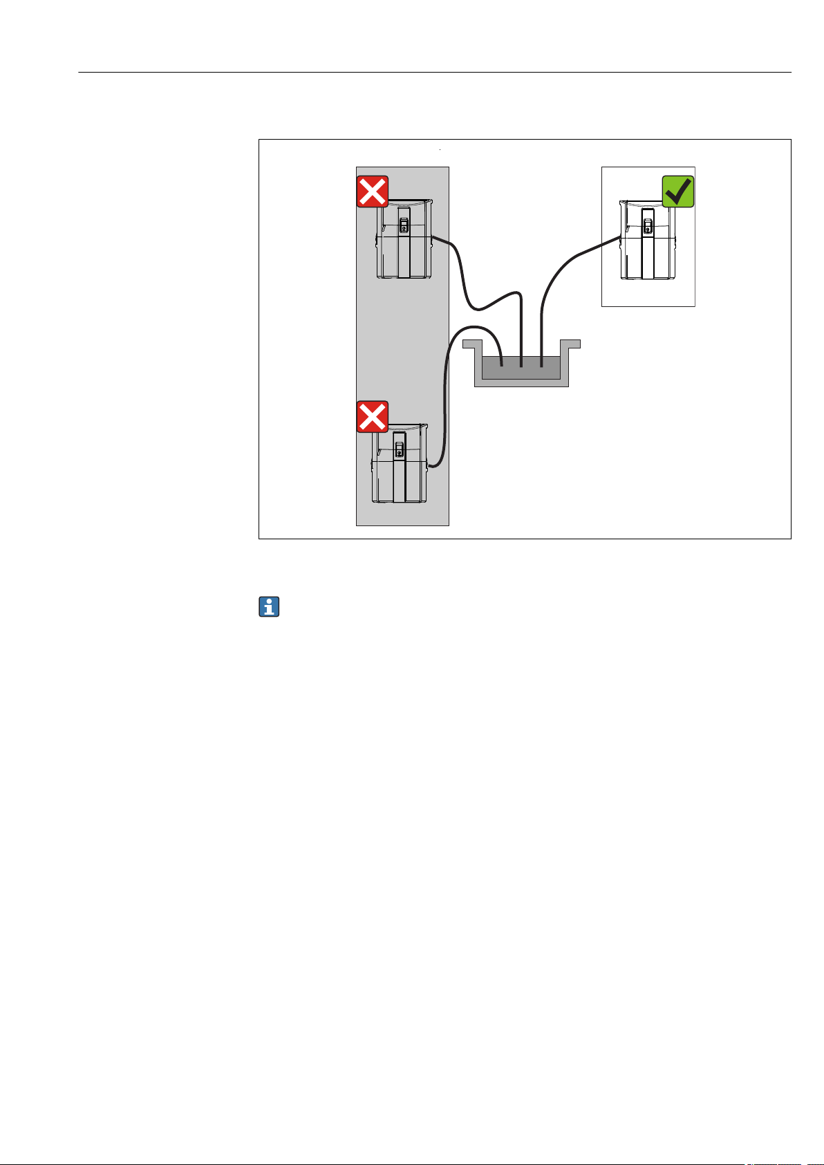
2 Installation site, example
The suction line must be routed with a downward slope to the sampling point. Avoid
siphon formation!
Note the following when erecting the device:
• Erect the device on a level surface.
• Securely connect the device at the fastening points to the surface underneath.
• Protect the device against additional heating (e.g. heater or direct sunlight in the case of
PS housing).
• Protect the device against mechanical vibrations.
• Protect the device against strong magnetic fields.
5.1.3 Connection for suctioning samples
• Maximum suction height: 8 m (26 ft)
• Maximum hose length: 30 m (98 ft)
• Diameter of hose connection: 10 mm (3/8")) internal diameter
• Intake speed:
> 0.5 m/s (> 1.6 ft/s) as per EN 25667, ISO 5667
> 0.6 m/s (> 1.9 ft/s) as per Ö 5893, US EPA
Note the following when erecting the device:
• Always route the suction line so that it slopes upwards from the sampling point to the
sampler.
• The sampler must be located above the sampling point.
• Avoid siphoning effects in the suction line.
Endress+Hauser 15
Page 16

Installation Liquiport CSP44
Requirements for the sampling point:
• Do not connect the suction line to pressurized systems.
• Use the suction filter to impede coarse and abrasive solids and solids which can cause
clogging.
• Immerse the suction line in the direction of flow.
• Take the sample at a representative point (turbulent flow, not directly at the bottom of
the channel).
Useful sampling accessories
Suction filter:
Impedes coarser solids and solids which can cause clogging.
5.1.4 Connection for sample intake on version with sample pump
• Maximum suction height: 8 m (26 ft)
• Maximum hose length: 30 m (98 ft)
• Diameter of hose connection: 10 mm (3/8")) internal diameter
• Intake speed:
> 0.5 m/s (> 1.6 ft/s) as per EN 25667, ISO 5667
> 0.6 m/s (> 1.9 ft/s) as per Ö 5893, US EPA
Note the following when erecting the device:
• Always route the suction line so that it slopes upwards from the sampling point to the
sampler.
• The sampler must be located above the sampling point.
• Avoid siphoning effects in the suction line.
Requirements for the sampling point:
• Do not connect the suction line to pressurized systems.
• Use the suction filter to impede coarse and abrasive solids and solids which can cause
clogging.
• Immerse the suction line in the direction of flow.
• Take the sample at a representative point (turbulent flow, not directly at the bottom of
the channel).
Useful sampling accessories
Suction filter:
Impedes coarser solids and solids which can cause clogging.
5.2 Installation
5.3 Connecting the suction line
1. When installing the device, take the installation conditions into account.
2. Open the device cover at the front fastening clasp.
3. Route the suction line from the sampling point to the device.
4. Screw the suction line onto the device's hose connection.
5.4 Post-installation check
1. Verify that the suction line is securely connected to the device.
2. Visually check that the suction line is installed correctly from the sampling point to
the device.
3. Verify that the rotating arm is correctly engaged.
16 Endress+Hauser
Page 17
Liquiport CSP44 Electrical connection
1
2
3
4
5
OFFON
6 Electrical connection
6.1 Connecting the sampler
WARNING
L
Device is live!
Incorrect connection may result in injury or death!
The electrical connection may be performed only by an electrical technician.
‣
The electrical technician must have read and understood these Operating Instructions
‣
and must follow the instructions contained therein.
Prior to commencing connection work, ensure that no voltage is present on any cable.
‣
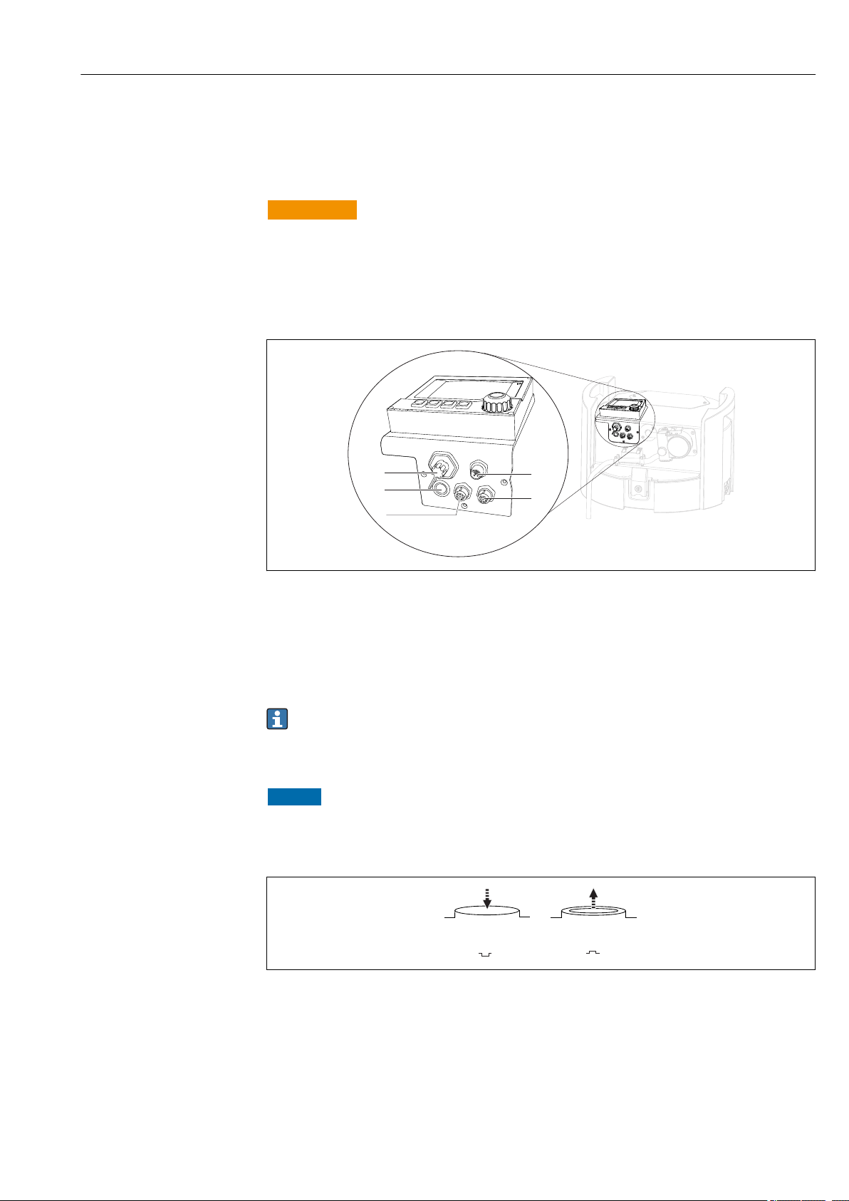
3 Electrical connections of the controller
1 Connection socket for charger
2 Socket for M12 sensor connector (optional)
3 Socket for M12 sensor connector (optional)
4 Connection socket for signal cable (optional)
5 Service interface
The polarity of the switch connections does not have to be taken into account.
6.1.1 Charging the battery
NOTICE
Defective batteries
The batteries can be destroyed if they are discharged completely.
To prevent complete discharge, move the switch to the "OFF" position.
‣
4 Switch position
A0029150
A0035816
Endress+Hauser 17
Page 18
Electrical connection Liquiport CSP44
Charge the battery before initial commissioning. It takes approx. 5 hours to fully charge
the battery. Please refer to the charger's operating manual for detailed information on the
charger.
Connect the device with the mains plug to the supply voltage.
‣
The battery starts charging as soon as the power unit is connected, regardless of
the switch position.
Only replace batteries with the following battery type: Panasonic LC-R127R2PG1.
Connecting the charger when the batteries are installed
The mains plug of the charger must be easily accessible so that the charger can be easily
disconnected from the power supply.
Connect the battery charger to the connection socket (item 1). If the battery is not fully
‣
charged, it is recharged by the charger.
Only use the chargers specified by the manufacturer. → 136
Connecting the charger when the batteries are removed
If you are charging batteries that have been removed, you require the adapter cable
(accessory no.: 71111882) to connect to the charger.
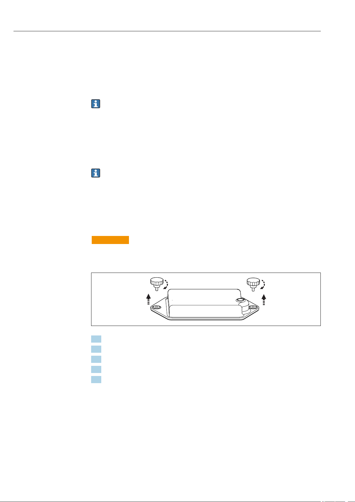
6.1.2 Removing the cover
WARNING
L
Device is live
Incorrect connection may result in injury or death
If a power unit or charger is connected, disconnect it from the power supply.
‣
1. Release both securing screws.
2. Remove the cover of the battery compartment.
3. Remove the old batteries and release the plug-in connections.
4. Connect the new batteries (pay attention to the battery polarity).
5. Insert the new batteries and secure the battery compartment cover.
A0035817
18 Endress+Hauser
Page 19
Liquiport CSP44 Electrical connection
1
2
6.2 Connecting modules and sensors
6.2.1 Connecting the sensors
Sensor connection
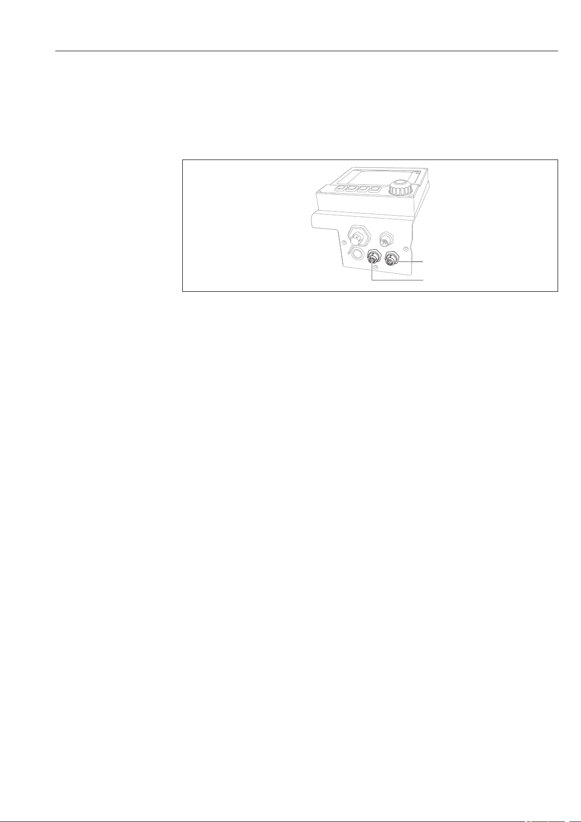
A0028664
5 Connection sockets for sensors
1 Socket for M12 sensor connector (= channel 1 for version with one sensor)
2 Socket for M12 sensor connector (= channel 2 for version with two sensors)
6.3 Terminal assignment for input/output signals
Input signals
• 2 analog signals 0/4 to 20 mA (optional)
• 2 binary signals > 100 ms pulse width or edge (optional)
Signals of digital sensors with Memosens protocol (optional)
Output signals
2 binary signals > 1 s pulse width or edge (optional)
2 current outputs 0/4 to 20 mA (optional)
Endress+Hauser 19
Page 20
Electrical connection Liquiport CSP44
+
-
+
-
-
-
+
+
R R
l l
Ui
Ui
1
(A)
(K)
(J)
(H)
(M)
(G)
(F)
(E)
(D)
(C)
(L)
(B)
(A)
(B)
(C)
(D)
(E)
(F)
(G)
(H)
(J)
(K)
(L)
(M)
1
2
3
4
U1-
U1+
B 1+I
B 1-I
B 2+I
B 2-I
B 1+O
B 1-O
B 2+O
B 2-O
AI1
In
AI1
GND
WH
BN
BU
RD
GN
YE
GY
PK
BK
VT
GY/PK
RD/BU
+
-
Ui
-
+
Ui
1
(A)
(K)
(J)
(H)
(M)
(G)
(F)
(E)
(D)
(C)
(L)
(B)
(A)
(B)
(C)
(D)
(E)
(F)
(G)
(H)
(J)
(K)
(L)
(M)
1
2
3
4
-
+
-
+
U1-
U1+
B 1+I
B 1-I
B 1+O
B 1-O
AI1
OUT
AI1
IN
AI1
GND
AI2
OUT
AI2
IN
AI2
GND
WH
BN
BU
RD
GN
YE
GY
PK
BK
VT
GY/PK
RD/BU
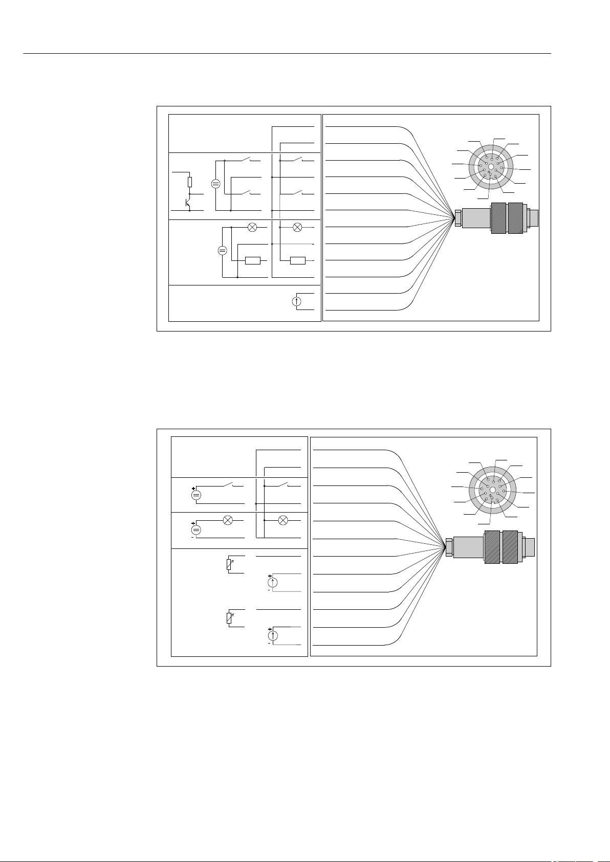
6.4 Signal cable connection (optional)
A0014162
6 Pin assignment and wiring diagram of signal cable (version K3)
1 Auxiliary voltage U: 24 V max. 30 mA load capacity
2 Binary inputs BI: > 20 ms, only extra-low voltage Ui £ 30 V DC
3 Binary outputs BO: only extra-low voltage Ui £ 30 V DC, max. current when using ext. auxiliary voltage (max.
200 mA)
4 Analog input AI: 0 to 20 mA, 4 to 20 mA
20 Endress+Hauser
7 Pin assignment and wiring diagram of signal cable (version K4)
1 Auxiliary voltage U: 24 V max. 30 mA load capacity
2 Binary input BI: > 20 ms, only extra-low voltage Ui £ 30 V DC
3 Binary output BO: only extra-low voltage Ui £ 30 V DC, max. current when using ext. auxiliary voltage (max.
200 mA)
4 Analog inputs AI: 0 to 20 mA, 4 to 20 mA
A0014197
Page 21
Liquiport CSP44 Electrical connection
+
-
Ui
-
+
Ui
-
+
Ui
1
(A)
(K)
(J)
(H)
(M)
(G)
(F)
(E)
(D)
(C)
(L)
(B)
(A)
(B)
(C)
(D)
(E)
(F)
(G)
(H)
(J)
(K)
(L)
(M)
1
2
3
4
-
+
A
-
+
A
U1-
U1+
B 1+I
B 1-I
B 1+O
B 1-O
B 2+O
B 2-O
I 1+O
I 1-O
I 2+O
I 2-O
WH
BN
BU
RD
GN
YE
GY
PK
BK
VT
GY/PK
RD/BU
A0014198
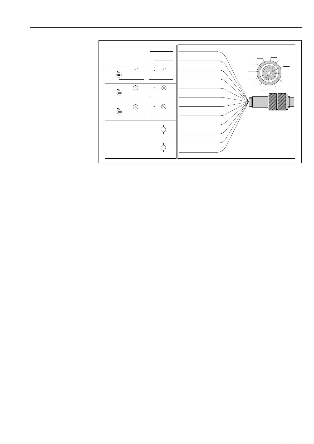
8 Pin assignment and wiring diagram of signal cable (version K5)
1 Auxiliary voltage U: 24 V max. 30 mA load capacity
2 Binary input BI: > 20 ms, only extra-low voltage Ui £ 30 V DC
3 Binary output BO: only extra-low voltage Ui £ 30 V DC, max. current when using ext. auxiliary voltage (max.
200 mA)
4 Analog inputs AI: 0 to 20 mA, 4 to 20 mA
6.5 Ensuring the degree of protection
Only the mechanical and electrical connections which are described in these instructions
and which are necessary for the required, designated use, may be carried out on the device
delivered.
Exercise care when carrying out the work.
‣
Individual types of protection permitted for this product (impermeability (IP), electrical
safety, EMC interference immunity, Ex protection) can no longer be guaranteed if, for
example :
• Covers are left off
• Different power units to the ones supplied are used
• Cable glands are not sufficiently tightened (must be tightened with 2 Nm (1.5 lbf ft) for
the permitted level of IP protection)
• Unsuitable cable diameters are used for the cable glands
• Modules are not fully secured
• The display is not fully secured (risk of moisture entering due to inadequate sealing)
• Loose or insufficiently tightened cables/cable ends
• Conductive cable strands are left in the device
Endress+Hauser 21
Page 22

Electrical connection Liquiport CSP44
6.6 Post-connection check
WARNING
L
Connection errors
The safety of people and of the measuring point is at risk! The manufacturer does not
accept any responsibility for errors that result from failure to comply with the instructions
in this manual.
Put the device into operation only if you can answer yes to all the following questions.
‣
Instrument status and specifications
Are the device and all the cables free from damage on the outside?
‣
Electrical connection
Are the mounted cables strain relieved?
‣
Are the cables routed without loops and cross-overs?
‣
Are the signal cables correctly connected as per the wiring diagram?
‣
Are all plug-in terminals securely engaged?
‣
Are all the connection wires securely positioned in the cable terminals?
‣
22 Endress+Hauser
Page 23
Liquiport CSP44 System integration
FieldCare
Service
FXA291
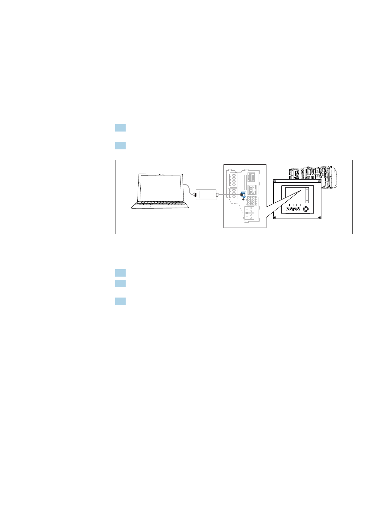
7 System integration
7.1 Service interface
You can connect the device to a computer via the service interface and configure it using
"FieldCare" . Furthermore, configurations can also be saved, transferred and documented.
7.1.1 Connection
1. Connect the service connector to the interface on the Liquiline base module and
connect it to the Commubox.
2. Connect the Commubox via the USB connection to the computer on which FieldCare
is installed.
A0039618
9 Connection overview
7.1.2 Establishing the data connection
1. Start FieldCare.
2. Establish a connection to the Commubox. To do so, select the "CDI Communication
FXA291" ComDTM.
3. Then select the "Liquiline CM44x" DTM and start configuration.
You can now start online configuration via the DTM.
Online configuration competes with onsite operation, i. e. each of the two options blocks
the other one. On both sides it is possible to take away access from the other side.
7.1.3 Operation
• In the DTM the menu structure corresponds to the onsite operation. The functions of the
Liquiline soft keys are found in the main window on the left.
• Clicking a menu name or a function corresponds to pressing the navigator.
• You can make your settings conveniently via the computer keyboard.
• You can use FieldCare to save logbooks, make backups of configurations and transfer
configurations to other devices.
• You can also print out configurations or save them as PDFs.
Endress+Hauser 23
Page 24
Operation options Liquiport CSP44
EH_CSF
09:11:05 31.03.2015
MODE
4
3
2
1
1
2
3
8 Operation options
8.1 Overview
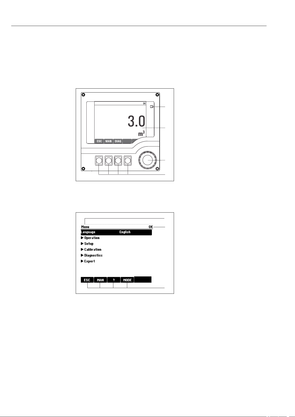
8.1.1 Display and operating elements
1
LED
2
Display (with red display background in alarm
3
condition)
4
Navigator (jog/shuttle and press/hold function)
Soft keys (function depends on menu)
10 Overview of operation
8.1.2 Display
11 Display (example)
A0025501
A0029090-EN
1
Menu path and/or device designation
2
Status display
3
Assignment of soft keys, e. g.:
ESC: escape or abortion of a sampling process
MAN: manual sample
?: Help, if available
MODE: switch the device to standby or cancel the
program
24 Endress+Hauser
Page 25
Liquiport CSP44 Operation options
MODE
MODE
MODE
Menu/Language
Menu/LanguageMenu/Language
MODE
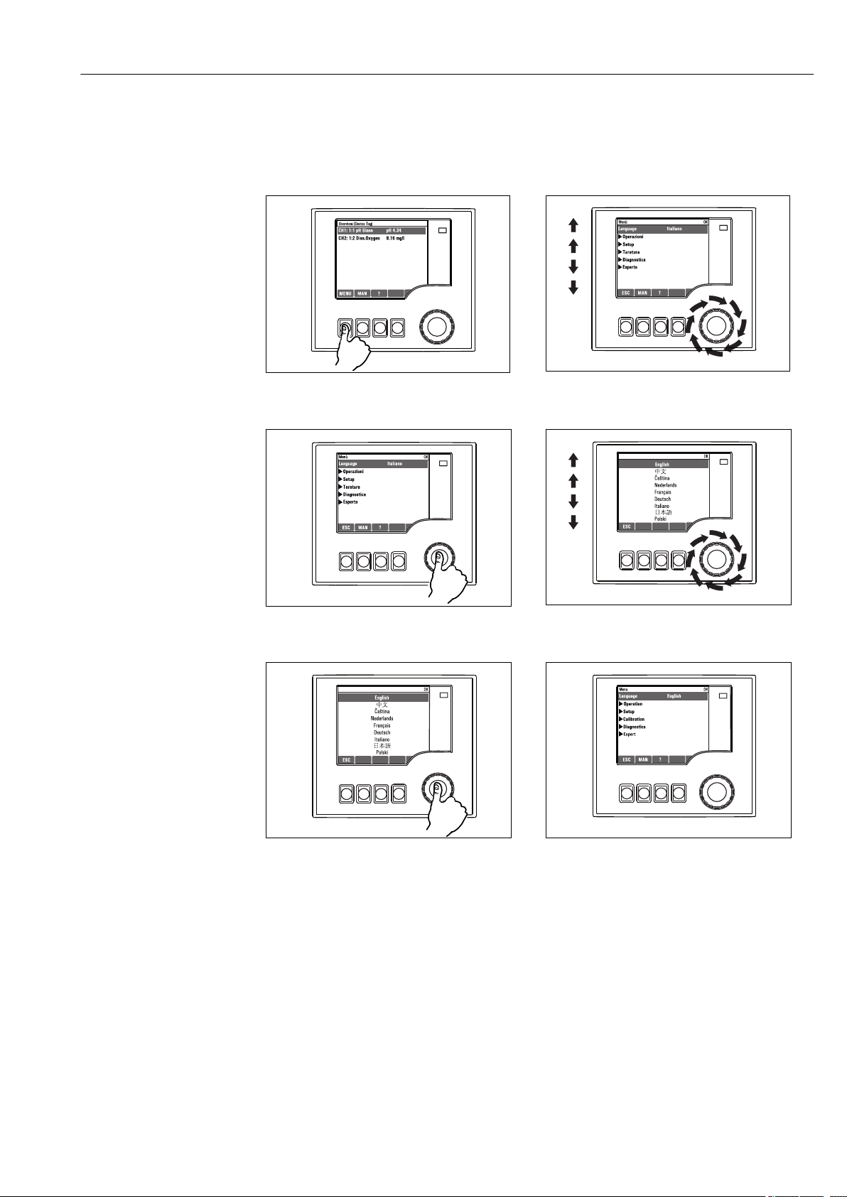
8.2 Access to the operating menu via the local display
8.2.1 Operating concept
Pressingthe soft key: selecting the menu directly
Pressingthe navigator: launching a function
Turningthe navigator: moving the cursor in the menu
Turningthe navigator: selecting a value (e.g. from a list)
Pressingthe navigator: accepting the new value
New setting is accepted
8.2.2 Locking or unlocking operating keys
Locking operating keys
Press the navigator for longer than 2 s.
‣
A context menu for locking the operating keys is displayed.
You have the choice of locking the keys with or without password protection. "With
Endress+Hauser 25
password" means that you can only unlock the keys again by entering the correct
Page 26

Operation options Liquiport CSP44
password. This password is set here: MenuSetupGeneral settingsExtended setupData
managementChange lock password
Choose whether you want to lock without or without a password.
‣
The keys are locked. No more entries can be made. In the soft key bar, you will see
the symbol.
The password is 0000 when the device is delivered from the factory. Make sure to
note down any changes to the password, as otherwise you will not be able to unlock
the keypad yourself.
Unlocking operating keys
1. Press the navigator for longer than 2 s.
A context menu for unlocking the operating keys is displayed.
2. Select Key unlock
The keys are unlocked immediately if you did not choose to lock with a password.
Otherwise you are asked to enter your password.
3. Only if keypad is password-protected: enter the right password.
The keys are unlocked. It is possible to access the entire onsite operation again.
The symbol is no longer visible on the display.
The password is 0000 when the device is delivered from the factory. Make sure to
note down any changes to the password, as otherwise you will not be able to unlock
the keypad yourself.
8.3 Configuration options
8.3.1 Display only
• You can only read the values but cannot change them.
• Typical read-only values are: sensor data and system information
• Example: Menu/Setup/Inputs/../Sensor type
8.3.2 Picklists
• You receive a list of options. In a few cases, these also appear in the form of multiple
choice boxes.
• Usually you just select one option; in rare instances you select one or more options.
• Example: Menu/Setup/General settings/Temperature unit
26 Endress+Hauser
Page 27
Liquiport CSP44 Operation options
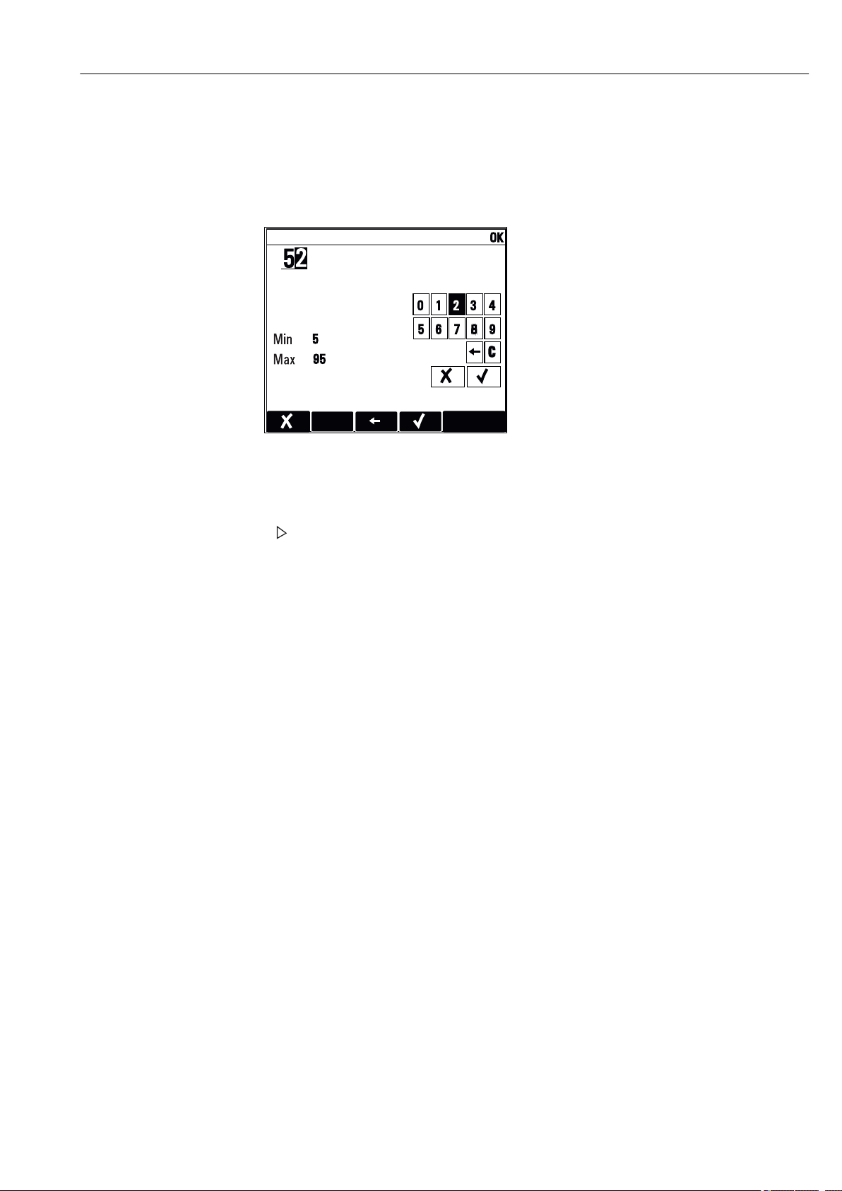
8.3.3 Numerical values
• You are changing a variable.
• The maximum and minimum values for this variable are shown on the display.
• Configure a value within these limits.
• Example: Menu/Operation/Display/Contrast
8.3.4 Actions
• You trigger an action with the appropriate function.
• You know that the item in question is an action if it is preceded by the following symbol:
• Examples of typical actions include:
• Deleting log entries
• Saving or loading configurations
• Triggering cleaning programs
• Examples of typical actions include:
• Start a sampling program
• Start manual sampling
• Saving or loading configurations
• Example: Menu/Manual sampling/Start sampling
Endress+Hauser 27
Page 28
Operation options Liquiport CSP44
E+H CSP4
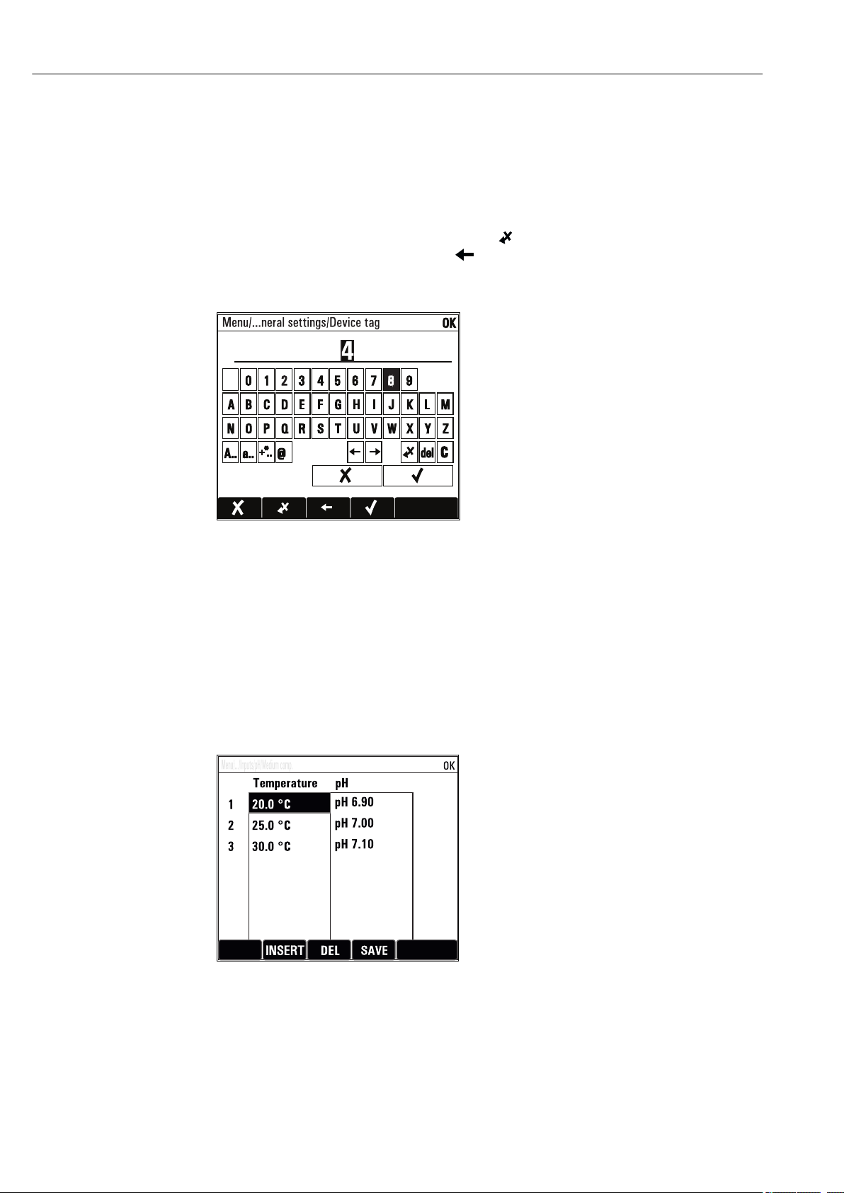
8.3.5 Free text
• You are assigning an individual designation.
• Enter a text. You can use the characters in the editor for this purpose (upper-case and
lower-case letters, numbers and special characters).
• Using the soft keys, you can:
• Cancel your entries without saving the data ()
• Delete the character in front of the cursor ( )
• Move the cursor back one position ( )
• Finish your entries and save ()
• Example: Menu/Setup/General settings/Device tag
8.3.6 Tables
• Tables are needed to map mathematical functions or to enter irregular interval samples.
• You edit a table by navigating through rows and columns with the navigator and
changing the values of the cells.
• You only edit the numerical values. The controller automatically takes care of the
engineering units.
• You can add lines to the table ( INSERT) or delete lines from the table ( DEL).
• Afterwards, you save the table ( SAVE).
• You can also cancel your entries any time using the soft key.
• Example: Menu/Setup/Inputs/pH/Medium comp.
28 Endress+Hauser
Page 29
Liquiport CSP44 Commissioning
OFFON
9 Commissioning
9.1 Function check
WARNING
L
Incorrect connection, incorrect supply voltage
Safety risks for staff and device malfunctions!
Check that all connections have been established correctly in accordance with the
‣
wiring diagram.
Ensure that the supply voltage matches the voltage indicated on the nameplate.
‣
Saving displays as a screenshot
Via the local display, you can take screenshots at any time and save them to an SD
card.
1. Insert an SD card into the SD card slot in the basic module.
2. Press the navigator button for at least 3 seconds.
3. In the context menu select the "Screenshot" item.
The current screen is saved as a bitmap file to the SD card in the "Screenshots"
folder.
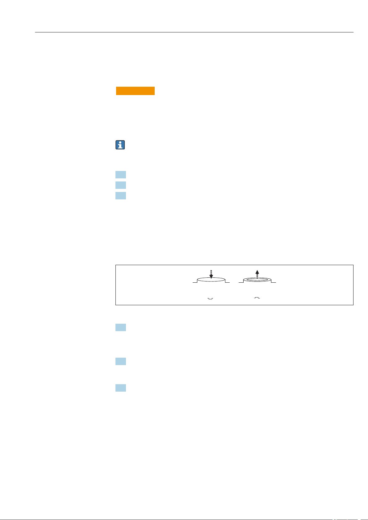
9.2 Switching on the measuring device
The device is delivered with a built-in rechargeable battery. The switch in the battery cover
is set to "OFF".
A0035816
12 Switch position
1. Prior to initial commissioning, charge the batteries by connecting the power unit.
The battery starts charging as soon as the power unit is connected, regardless of
the switch position. It takes approx. 5 hours to fully charge the battery. Please
refer to the charger's operating manual for detailed information on the charger.
2. Once the charging process is complete, press the switch on the battery cover to the
"ON" position.
The transmitter starts up.
3. Wait for the boot process to complete.
Disconnecting the batteries when the sampler is not in use:
Press the switch on the battery cover to the "OFF" position.
‣
When the switch is in the "OFF" position, it provides reliable and effective
protection against the battery discharging completely and thus becoming
irreparably damaged.
Endress+Hauser 29
Page 30
Commissioning Liquiport CSP44
9.3 Setting the operating language
Configuring the language
If you have not already done so, close the housing cover and screw the device closed.
1. Connect the rechargeable battery (see "Electrical connection" section).
Wait for the initialization to finish.
2. Press the soft key MENU . Set your language in the top menu item.
The device can now be operated in your chosen language.
9.4 Configuring the measuring device
9.4.1 Start screen
You can find the following menu items and soft keys on the initial screen:
• Select sampling program
• Edit program %0V
• Start program %0V
• MENU
• MAN
• MEAS
• MODE
1)
1)
9.4.2 Display behavior
Menu/Operation/Display
Function Options Info
Contrast 5 to 95 %
Factory setting
50 %
Backlight Selection
• On
• Off
• Automatic
Factory setting
Automatic
Screen rotation Selection
• Manual
• Automatic
Factory setting
Manual
Current program: Read only The name of the sampling program currently
Status Read only Active
Start Action The selected sampling program is started.
Adjust the screen settings to suit your working
environment.
Backlight = Automatic
The backlighting is switched off automatically
after a short time if a button is not pressed. It
switches back on again as soon as you press the
navigator button.
Backlight = On
The backlighting does not switch off
automatically.
If Automatic is selected, the single‐channel
measured value display switches from one
channel to the next every second.
selected is displayed.
The sampling program has been started and the
device takes a sample as per the set parameters.
Inactive
No sampling program has been started, or a
program that was running has been stopped.
1) "%0V" here stands for text that depends on the context. This text is generated automatically by the software and inserted in place of %0V.
30 Endress+Hauser
Page 31

Liquiport CSP44 Commissioning
Menu/Operation/Display
Function Options Info
Measurement Current measured values at the inputs are
displayed. Analog and binary inputs cannot be
modified here.
Show summary of current
program
Show summary of inputs The configured counters of the analog and
The bottle statistics for the sampler are
displayed. The statistics appear for each
individual bottle after the start of the program.
You can find more information in the Chap.
"Bottle statistics".
binary input are displayed.
Max. 8 lines
9.4.3 User definable screens
Menu/Operation/User definable screens
Function Options Info
Meas. screen 1 ... 6 You can create 6 measuring screens of your own
and give them a name. The functions are
identical for all 6 measuring screens.
Meas. screen Selection
• On
• Off
Factory setting
Off
Label Customized text, 20
characters
Number of lines 1 to 8
Factory setting
8
Line 1 ... 8 User interface
Label
Source of data Selection
• None
• See list in "Info" column
Factory setting
None
Measured value
Source of data is an
input
Selection
Depends on the input
Factory setting
None
Once you have defined your own measuring
screen, you can switch it on here. You can find
the new screen under User definable screens.
Name of the measuring screen
Appears in the status bar of the display.
Specify the number of measured values
displayed.
Specify the content of Label in the submenu of
each line.
Select a source of data.
‣
You can choose from the following:
• Sensor inputs
• Binary inputs
• Current inputs
• Temperature
• Memosens sensor input (optional)
• Fieldbus signals
• Mathematical functions
• Binary inputs and outputs
• Current outputs
• Relay
• Measuring range switching
You can display different main, secondary and
raw measured values depending on the type of
input.
No options can be selected for outputs here.
Endress+Hauser 31
Page 32

Commissioning Liquiport CSP44
Menu/Operation/User definable screens
Function Options Info
Label Customized text, 20
characters
Set label to "%0V"
1) "%0V" here stands for text that depends on the context. This text is generated automatically by the
software and inserted in place of %0V. In the simplest situations, the generated text could be the name of
the measuring channel, for example.
1)
Action If you perform this action you accept the
User-defined name for the parameter to be
displayed
parameter name that is automatically suggested.
Your own parameter name (Label) is lost!
9.4.4 Basic setup
Making basic settings
1. Switch to the Setup/Basic setup menu.
Make the following settings.
2. Device tag: Give your device any name of your choice (max. 32 characters).
3. Set date: Correct the set date if necessary.
4. Set time: Correct the set time if necessary.
5. Number of bottles: Correct the set number of bottles if necessary.
6. Bottle volume: Correct the set bottle volume if necessary.
For quick commissioning, you can ignore the additional settings for outputs etc.
You can make these settings later in the specific menus.
7. To return to the display overview: press the soft key for ESC for at least one second.
Your sampler now works with your basic settings.
If you wish to configure your most important input and output parameters in the Basic
setup :
Configure the current inputs, limit switches, cleaning cycles and device diagnostics with
‣
the following submenus.
9.4.5 Sampling programs
Difference between program types
The following box provides an overview of the differences between the Basic, Standard and
Advanced program types.
Basic (1 sampling program)
Start condition:
• Immediate
• Date/time
• Immediate activation
• Time-paced, volume-paced or
flow-paced (CTCV, VTCV, CTVV),
external signal,
• Bottle change after time or
number of samples, external
signal
• Bottle synchronization
• Multiple bottles
Stop condition:
• Program end
• Continuous operation
32 Endress+Hauser
Page 33

Liquiport CSP44 Commissioning
15000 ml
MODE
1
Menu/Manual sampling
Distribution position
Bottle 1
Multiplier
Standard (1 sampling program with 1-5 sub-programs)
Start condition:
• Immediate
• Date/time
• Volume
Advanced (1 sampling program with 1-24 sub-programs)
Start condition:
• Immediate
• Date/time
• Volume
• External signal
• Immediate activation, individual
times, multiple times, interval,
deactivation of sub-program 1
• Time-paced, volume-paced or
flow-paced (CTCV, VTCV, CTVV),
external signal
• Bottle change after time or
number of samples, external
signal
• Bottle synchronization
• Multiple bottles
• Immediate activation, individual
times, multiple times, interval,
event, external start,
deactivation of sub-program 1
• Time-paced, volume-paced or
flow-paced (CTCV, VTCV, CTVV),
single sample, sample table,
external signal
• Bottle change after time or
number of samples, external
signal, fieldbus
• Sample synchronization
• Bottle synchronization
• Multiple bottles
Stop condition:
• Program end
• Continuous operation
• Date/time
Stop condition:
• Program end
• Continuous operation
• Date/time
Manual sampling
A0036865-EN
1. Manual sampling is triggered by the MAN soft key. This pauses any program
currently running.
The current bottle configuration and the current sample volume are displayed.
You can select the distributor position. In peristaltic systems, you can also change
the sample volume.
In vacuum systems, Multiplier a multiple of a single manual sample can be taken
under . Specification of Multiplierrange of adjustment 1 to 50.
2. Select Start sampling
A new screen is displayed indicating the progress of the sampling process.
Endress+Hauser 33
Page 34

Commissioning Liquiport CSP44
15000 ml
100 ml
144
MODE
144
2
3. After manual sampling, a running program can be displayed and continued with the
ESC ESC button.
The sample volume for "Manual sampling" is not taken into account in the
calculated bottle volumes.
Programming for automatic sampling
Create a simple sampling program in the general overview under Select sampling
program/New/Basic or in the menu Menu/Setup/Sampling programs/Setup
program/New/Basic :
1. Enter the "Program name".
2. The settings from the Basic setup for bottle configuration and bottle volume are
displayed.
3. Sampling mode=Time paced CTCV is preset.
4. Enter the Sampling interval .
5. Enter the Sampling volume per sample. (For version with vacuum pump, configure
under Menu/Setup/General settings/Sampling .)
6. Select the Bottle change mode after number of samples or time for average samples.
With the option "Bottle change after a time", you can enter the change time and bottle
synchronization (None, 1st bottle change time, 1st time of change + bottle number).
The description for this can be found in the "Bottle synchronization" section.
With the option "Bottle change after a time", you can choose the bottle
synchronization before the start condition (None, 1st bottle change time, 1st time of
change + bottle number). The description for this can be found in the "Bottle
synchronization" section.
1. For Multiple bottles enter the number of bottles the sample should be distributed
over.
2. Start condition: immediately or after date/time
3. Stop condition: after program end or continuous operation.
4. Pressing the SAVE saves the program and ends data entry.
Example:
A0029242-EN
The program can be started.
34 Endress+Hauser
Page 35

Liquiport CSP44 Operation
10 Operation
10.1 Display
10.1.1 Measuring mode
To display the measured values, press the soft key MEAS in the start screen, or during
‣
operation press STAT under Measurement.
Press the navigator button to change the mode
There are various display modes:
• Channel overview
The names of all the channels, the sensor type connected and the current main value are
displayed.
• Main value of the selected channel
The name of the channel, the sensor type connected and the current main value are
displayed.
• Main value and secondary value of the selected channel
The name of the channel, the connected sensor type and the current main value and
secondary value are displayed.
Temperature sensor 1 has a special function. The states of the compressor, ventilator
and heater are displayed (on/off).
• All the measured values of all the inputs and outputs
The current main value and secondary value as well as all the raw values are displayed.
• User-defined measuring screens
You configure what values you want to display. You can choose from all the measured
values of physical and "virtual" sensors (calculated using mathematical functions) and
output parameters.
In the first 3 modes, you can switch between channels by turning the navigator. In
addition to having an overview of all the channels, in the 4th mode you can also select
a value and press the navigator to see more details for the value. You can also find
your user-defined screens in this mode.
10.1.2 Device status
Icons on the display alert you to special device states.
Icon Location Description
Header bar Diagnostic message "Failure"
Header bar Diagnostic message "Maintenance request"
Header bar Diagnostic message "Check"
Header bar Diagnostic message "Out of specification"
Header bar Fieldbus or TCP/IP communication active
Header bar Hold active (for sensors)
At measured value Hold for the actuator (current output, limit switch etc.) is active
At measured value
At measured value Measured value in "Bad" or "Alarm" state
At measured value Automatic temperature compensation active (for sensors)
At measured value Manual temperature compensation active (for sensors)
Header bar Simulation mode active or Memocheck SIM connected
At measured value The measured value is influenced by a simulated value
Endress+Hauser 35
1)
An offset has been added to the measured value
Page 36

Operation Liquiport CSP44
Icon Location Description
At measured value The displayed measured value is simulated (for sensors)
Header bar Controller is active
1) Only pH or ORP measurement
If two or more diagnostic messages occur simultaneously, only the icon for the
message with the highest priority is shown on the display (for the order of priority
according to NAMUR, → 95).
10.1.3 Assignment views
Assignment views, e.g. Channel assignment view, appear as the last function in many
sections of the menu. You can use this function to see which actuators or functions are
connected to an input or output. The assignments appear in hierarchical order.
10.2 General settings
10.2.1 Basic settings
Some settings are visible with optional hardware only.
Menu/Setup/General settings
Function Options Info
Device tag Customized text, 32
characters
Temperature unit Selection
• °C
• °F
• K
Factory setting
°C
Current output range Selection
• 0..20 mA
• 4..20 mA
Factory setting
4..20 mA
Failure current 0.0 to 23.0 mA
Factory setting
22.5 mA
The value for Failure current should be outside the measuring range. If you decided that your Current
output range = 0..20 mA you should set an error current between 20.1 and 23 mA. If the Current
output range = 4..20 mA you could also define a value < 4 mA as the error current.
The device allows an error current within the measuring range. In such instances pay attention to any
effects this may have on your process.
Select any name for your controller, e.g. use
‣
the TAG name.
In accordance with Namur NE43, the linear
range is from 3.8 to 20.5 mA (4..20 mA) or
from 0 to 20.5 mA (0..20 mA). If the range is
exceeded or undershot, the current value stops
at the range limit and a diagnostic message (460
or 461) is output.
The function meets NAMUR NE43.
Set the current value that should be output
‣
at the current outputs in the event of an
error.
36 Endress+Hauser
Page 37

Liquiport CSP44 Operation
Menu/Setup/General settings
Function Options Info
Alarm delay 0 to 9999 s
Factory setting
0 s
Device hold Selection
• Disabled
• Enabled
Factory setting
Disabled
The software displays only the errors that are
present longer than the set delay time. This
makes it possible to suppress messages that only
occur briefly and are caused by normal processspecific fluctuations.
You can enable an immediate, general hold (for
sensors) here. The function acts in the same way
as the HOLD soft key in the screens.
10.2.2 Date and time
Menu/Setup/General settings/Date/Time
Function Options Info
Set date Depends on the format Editing mode:
Day (two-digit): 01 to 31
Month (two-digit): 01 to 12
Year (four-digit): 1970 to 2106
Set time Depends on the format Editing mode:
hh (hour): 00 to 23 / 0 am to 12 pm
mm (minutes): 00 to 59
ss (seconds): 00 to 59
Extended setup
Date format Selection
• DD.MM.YYYY
• YYYY-MM-DD
• MM-DD-YYYY
Factory setting
DD.MM.YYYY
Time format Selection
• hh:mm am (12h)
• hh:mm (24h)
• hh:mm:ss (24h)
Factory setting
hh:mm:ss (24h)
Time zone Selection
• None
• Choice of 35 time zones
Factory setting
None
DST Selection
• Off
• Europe
• USA
• Manual
Factory setting
Off
Select a date format.
‣
Choose between 12-hour display or 24-hour
‣
display. Seconds can also be displayed with
the latter version.
None = Greenwich Mean Time (London).
The controller adapts the summertime/normal
time changeover automatically if you choose
European or American daylight saving time.
Manual means that you can specify the start and
end of daylight saving time yourself. Here, two
additional submenus are displayed in which you
specify the changeover date and time.
Endress+Hauser 37
Page 38

Operation Liquiport CSP44
10.2.3 Hold settings
Menu/Setup/General settings/Hold settings
Function Options Info
Settings automatic Hold
Hold release time 0...600 s
Factory setting
0 s
Setup menu Selection
Diagnostics menu Decide whether a hold should be output at the
Calibration active Factory setting
• Disabled
• Enabled
Factory setting
Disabled
Enabled
If a device-specific hold is enabled, any cleaning that was previously started is
stopped. You can only start a manual cleaning if a hold is active. The hold has no
influence on the sampling.
The hold is maintained for the duration of the
delay time when you switch to the measuring
mode.
current output when the particular menu is
opened.
10.2.4 Logbooks
Logbooks record the following events:
• Calibration/adjustment events
• Operator events
• Diagnostic events
• Programming events
You define how the logbooks should store the data.
In addition, you can also define individual data logbooks .
1. Assign the logbook name.
2. Select the measured value to be recorded.
3. Set the scan time (Scan time).
You can set the scan time individually for every data logbook.
Further information on the logbooks: .
Menu/Setup/General settings/Logbooks
Function Options Info
Logbook ident Customized text, 16
characters
Event logbook Selection
• Off
• Ring buffer
• Fill up buffer
Factory setting
Ring buffer
Part of the file name when exporting a logbook
All diagnostic messages are recorded
Ring buffer
If the memory is full, the most recent entry
automatically overwrites the oldest entry.
Fill up buffer
If the memory is full, there is an overflow,i. e.
you cannot store any new values. The controller
displays a corresponding diagnostic message.
The memory then has to be cleared manually.
38 Endress+Hauser
Page 39

Liquiport CSP44 Operation
Menu/Setup/General settings/Logbooks
Function Options Info
Logbook program Selection
• Off
• Ring buffer
• Fill up buffer
Factory setting
Ring buffer
Overflow warnings
Event logbook = Fill up buffer
Calibration logbook Selection
Diagnostic logbook
Configuration logbook
Data logbooks
New You can create a maximum of 8 data logbooks.
Logbook name Customized text, 20
Source of data Selection
Measured value Selection
Scan time 0:00:01 to 1:00:00
Data logbook Selection
Overflow warnings
Event logbook =
Fill up buffer
Add another
logbook
Finished Action This allows you to exit the New menu.
• Off
• On
Factory setting
Off
characters
• Sensor inputs
• Controller
• Current inputs
• Temperature
• Fieldbus signals
• Binary inputs
• Mathematical functions
Factory setting
None
Depends on Source of data
Factory setting
None
Factory setting
0:01:00
• Ring buffer
• Fill up buffer
Factory setting
Ring buffer
Selection
• Off
• On
Factory setting
Off
Action Only if you want to create another data logbook
All program cycles are recorded
Ring buffer
If the memory is full, the most recent entry
automatically overwrites the oldest entry.
Fill up buffer
If the memory is 80 % full, the device displays a
diagnostic message.
If the memory is full, there is an overflow, i. e. no
new values can be saved. The controller displays
a corresponding diagnostic message. The
memory then has to be cleared manually.
Decide whether you want to receive a
‣
diagnostic message if the fill buffer of the
relevant logbook overflows.
Select a data source for the logbook entries.
‣
You can choose from the following:
• Connected sensors
• Available controllers
• Current inputs
• Fieldbus signals
• Binary input signals
• Mathematical functions
You can record different measured values
depending on the data source.
Minimum time interval between two entries
Format: H:MM:SS
Ring buffer
If the memory is full, the most recent entry
automatically overwrites the oldest entry.
Fill up buffer
If the memory is full, there is an overflow,i. e. no
new values can be saved. The controller displays
a corresponding diagnostic message. The
memory then has to be cleared manually.
Decide whether you want to receive a
‣
diagnostic message if the fill buffer of the
relevant logbook overflows.
immediately. You add a new data logbook at a
later date using New.
Endress+Hauser 39
Page 40

Operation Liquiport CSP44
Menu/Setup/General settings/Logbooks
Function Options Info
Start/stop
simultaneously
Logbook name The name of this submenu is based on the name
This menu appears several times if you have several data logbooks.
Source of data Read only This is for information purposes only. If you
Measured value
Log time left
Event logbook =
Fill up buffer
Log size
Event logbook =
Fill up buffer
Logbook name Customized text, 20
Scan time 0:00:01 to 1:00:00
Data logbook Selection
Overflow warnings
Event logbook =
Fill up buffer
Action Appears if you have created more than one data
logbook. With one mouse click, you can start or
stop recording all the data logbooks.
of the logbook and only appears once you have
created a logbook.
want to record another value, delete this logbook
and create a new data logbook.
Read only Displays the days, hours and minutes remaining
until the logbook is full.
Read only Displays the number of entries remaining until
the logbook is full.
You can change the name here again.
characters
As above
Factory setting
0:01:00
• Ring buffer
• Fill up buffer
Factory setting
Ring buffer
Selection
• Off
• On
Factory setting
Off
Minimum time interval between two entries
Format: H:MM:SS
Ring buffer
If the memory is full, the most recent entry
automatically overwrites the oldest entry.
Fill up buffer
If the memory is full, there is an overflow, i. e. no
new values can be saved. The controller displays
a corresponding diagnostic message. The
memory then has to be cleared manually.
Decide whether you want to receive a
‣
diagnostic message if the fill buffer of the
relevant logbook overflows.
40 Endress+Hauser
Page 41

Liquiport CSP44 Operation
Menu/Setup/General settings/Logbooks
Function Options Info
Line plotter Menu to define the graphic display
Axes Selection
• Off
• On
Factory setting
On
Orientation Selection
• Horizontal
• Vertical
Factory setting
Horizontal
X-Description Selection
Y-Description
Grids
Pitches
X Pitch/Grid distance 10 to 50%
Y Pitch/Grid distance
Remove Action This action removes the data logbook. Any data
• Off
• On
Factory setting
On
Factory setting
10 %
Should the axes (x, y) be displayed (On) or not
(Off)?
You can choose whether the value curves should
be displayed from left to right (Horizontal) or
from top to bottom (Vertical). If you want to
display two data logbooks simultaneously, make
sure that both logbooks have the same settings
here.
Decide whether a description should be
‣
displayed for the axes and whether gridlines
should be shown. In addition, you can also
decide whether pitches should be displayed.
Determine the pitch.
‣
that have not been saved are lost.
Example: New data logbook (Setup/General settings/Logbooks/Data logbooks/New)
1. Make the settings:
• Logbook name
Assign a name. Example: "01".
• Source of data
Select a data source. Example: Sensor connected to channel 1 (CH1).
• Measured value
Select the measured value to be recorded. Example: pH value.
• Scan time
Specify the time interval between two logbook entries.
• Data logbook
Activate the logbook: specify the data storage method.
2. ../Finished: Perform the action.
The device shows the new logbook in the list of data logbooks.
3. Select data logbook "01".
Additional display: Log time left.
4. Only in the case of Fill up buffer:
Decide to set Overflow warning: On or Off.
On: The device displays a diagnostic message in the event of memory overflow.
5. Line plotter submenu: Specify the type of graphic representation.
10.2.5 Configuring the sampling depending on the device version
The list of functions displayed depends on the device version selected with:
• Vacuum pump
• Peristaltic pump
• Distribution drive
• Sampling assembly:
Endress+Hauser 41
1)
2)
3)
4)
Page 42

Operation Liquiport CSP44
Menu/Setup/General settings/
Function Options Info
Sampling
Number of bottles Choice of all possible bottle
combinations
Bottle volume 0 to 100000 ml
Factory setting
Depends on the bottle
configuration
Distribution parking
(only for version with
distributor drive)
3)
Selection
• Back
• None
Factory setting
Back
Distribution reference
(only for version with
distributor drive)
Selection
• Pre sampling
• Pre bottle change
• Pre program start
Factory setting
Pre sampling
Power failure Selection
• Resume program
• Stop program
Factory setting
Resume program
Sample retries
1), 2), 3)
0 to 3
Factory setting
0
Sampling delay 0 to 99 s
Factory setting
0 s
Liquid detection Selection
• Automatic
• Semi automatic
• Off
Factory setting
Automatic
Rinse cycles 0 to 3
Factory setting
0
The bottle configuration you ordered
is preset in the device.
If continuous operation is selected for
a sampling program, there is the
danger of overfilling the bottles. Do
not forget to empty the bottles!
Causes the distribution arm to go to
the center at the back or remain
parked in the current position when
the device is started or the program is
ended.
The distributor arm goes through a
reference point depending on the
option selected.
Decide how the sampler should react
when it is energized after a power
failure.
Resume program:
• Time and flow-paced
The program calculates the omitted
samples and enters them in the
logbook as failed. When the
program is restarted, it continues
where it was interrupted.
• Flow-paced
No samples are entered in the
logbook during the power failure.
When the program is restarted, it
continues where it was interrupted.
If sampling is started and no sample is
drawn in, sampling can be repeated
up to 3 times.
The start of the sampling cycle can be
delayed by up to 99 s. The binary
output is switched without any delay.
If "Semiautomatic" is selected, the
purge times and intake times can be
defined separately.
Off:
The definition of the purge times and
intake times is completely timecontrolled.
Automatic:
The last intake time determined is the
new purge time.
Semi automatic:
If the suction heights tend to vary
greatly.
The suction line is rinsed with the
sample up to 3 times.
42 Endress+Hauser
Page 43

Liquiport CSP44 Operation
Menu/Setup/General settings/
Function Options Info
Safety interlock(optional) Selection
Off
Factory setting
Off
Diagnostics settings
Pump tube life
Control Selection
Warning 10 to 50 h
Alarm 10 to 50 h
Totalizer 00-00:00 to 49710-06:28
Reset Action The tube life counter is reset to 0:00
2)
• Off
• On
Factory setting
On
Factory setting
30 h
Factory setting
30 h
Factory setting
00-00:00
If the peristaltic pump is opened, the
safety interlock stops all the
functions.
Indicates the pump hose has to be
exchanged.
When the tube has been in operation
for this length of time, a diagnostic
message is displayed to indicate that
the tube should be replaced in time.
Operating time of the current pump
hose in days, hours and minutes
h.
10.2.6 Advanced setup
Diagnostics settings
The list of diagnostic messages displayed depends on the path selected. There are devicespecific messages, and messages that depend on what sensor is connected.
Menu/Setup/(General settings or Inputs<Sensor channel>)/Extended setup/Diagnostics settings/Diag.
behavior
Function Options Info
List of diagnostic messages
Diag. code Read only
Diagnostic message Selection
• On
• Off
Factory setting
Depends on the message
Failure current Selection
• On
• Off
Factory setting
Depends on the message
Select the message to be changed. Only then
‣
can you make the settings for this message.
You can deactivate or reactivate a diagnostic
message here.
Deactivating means:
• No error message in the measuring mode
• No error current at the current output
Decide whether an error current should be
‣
output at the current output if the diagnostic
message display is activated.
In the event of general device errors, the
error current is output at all the current
outputs. In the event of channel-specific
errors, the error current is only output at
the assigned current output.
Endress+Hauser 43
Page 44

Operation Liquiport CSP44
Menu/Setup/(General settings or Inputs<Sensor channel>)/Extended setup/Diagnostics settings/Diag.
behavior
Function Options Info
Status signal Selection
• Maintenance (M)
• Out of specification (S)
• Function check (C)
• Failure (F)
Factory setting
Depends on the message
Diag. output Selection
• None
• Alarm relay
• Binary output
• Relay 1 to n (depends on
the device version)
Factory setting
None
An alarm relay is always available, regardless of the device version. Other relays are optional.
The messages are divided into different error
categories in accordance with NAMUR NE 107.
Decide whether you want to change a status
‣
signal assignment for your application.
You can use this function to select a binary
output to which the diagnostic message should
be assigned.
For sensors with the Memosens protocol: Before
being able to assign the message to an output
you must first configure a relay output to
Diagnostics .
(Menu/Setup/Outputs: Assign the Diagnostics
function and set the Operating mode to as
assigned .)
Cleaning program Selection
• None
• Cleaning 1
• Cleaning 2
• Cleaning 3
• Cleaning 4
Factory setting
None
Detail information Read only Here you can find more information on the
Decide whether the diagnostic message
‣
should trigger a cleaning program.
You can define the cleaning programs under:
Menu/Setup/Additional functions/Cleaning.
diagnostic message and instructions on how to
resolve the problem.
Modbus
Menu/Setup/General settings/Extended setup/Modbus
Function Options Info
Enable Selection
• Off
• On
Factory setting
On
Termination Read only If the device is the last in the bus, you can
You can switch off communication at this point.
The software can then only be accessed via local
operation.
terminate via the hardware.
44 Endress+Hauser
Page 45

Liquiport CSP44 Operation
Menu/Setup/General settings/Extended setup/Modbus
Function Options Info
Settings
Transmission Mode Selection
• TCP
• RTU
• ASCII
Factory setting
(Modbus-RS485 only)
RTU
Parity
Modbus-RS485 only
Byte order Selection
Watchdog 0 to 999 s
Selection
• Even (1 Stopbit)
• Odd (1 Stopbit)
• None (2 Stopbit)
Factory setting
Even (1 Stopbit)
• 1-0-3-2
• 0-1-2-3
• 2-3-0-1
• 3-2-1-0
Factory setting
1-0-3-2
Factory setting
5 s
The transmission mode is displayed depending
on the version ordered.
In the case of RS485 transmission, you can
choose between RTU and ASCII . There are no
choices for Modbus-TCP.
If no data transmission takes place for longer
than the time set, this is an indicator that
communication has been interrupted. After this
time, input values received via the Modbus are
considered to be invalid.
Data management
Firmware update
Please contact your local sales office for information on firmware updates available
for your controller and its compatibility with earlier versions.
Current firmware version : Menu/Diagnostics/System information/.
Back up your current setup and your logbooks to an SD card.
‣
To install a firmware update, you must have the update available on an SD card.
1. Insert the SD card into the controller card reader.
2. Go to Menu/Setup/General settings/Extended setup/Data management/
Firmware update .
The update files on the SD card are displayed.
3. Select the desired update and select yes when asked the following:
The current firmware will be overwritten.
After this the device will reboot.
Do you want to proceed?
The firmware is loaded and the device is then started with the new firmware.
Saving the setup
Saving a setup offers the following advantages, among others :
• Copying settings for other devices
• Quick and easy switching between various setups, e. g. for different user groups or for
recurring sensor type changes
• Restoring a tried-and-tested setup, e. g. if you have changed a lot of settings and no
longer know what the original settings were
Endress+Hauser 45
Page 46

Operation Liquiport CSP44
1. Insert the SD card into the controller card reader.
2. Go to Menu/Setup/General settings/Extended setup/Data management/Save
setup .
3. Name: Assign a file name.
4. Then select Save .
If you have already assigned the file name, you will be asked whether you want to
overwrite the existing setup.
5. Use OK to confirm or cancel and assign a new file name.
Your setup is stored on the SD card and you can upload it quickly to the device at
a later date.
Loading the setup
When you load a setup, the current configuration is overwritten.
1. Insert the SD card into the controller card reader. A setup must have been saved to
the SD card.
2. Go to Menu/Setup/General settings/Extended setup/Data management/Load
setup .
A list of all the setups on the SD card is displayed.
An error message is displayed if there is no valid setup on the card.
3. Select the desired setup.
A warning is displayed:
The current parameters will be overwritten and the device will reboot.
Warning: Please note that cleaning and controller programs can be active.
Do you want to proceed?
4. Use OK to confirm or cancel.
If you select OK to confirm, the device restarts with the desired setup.
Exporting the setup
Exporting a setup offers the following advantages, among others:
• Export in XML format with a stylesheet for formatted display in an XML-compatible
application, such as . Microsoft Internet Explorer
• Importing the data (drag and drop the XML file into a browser window)
1. Insert the SD card into the controller card reader.
2. Go to Menu/Setup/General settings/Extended setup/Data management/Export
setup .
3. Name: Assign a file name.
4. Then select Export .
If you have already assigned the file name, you will be asked whether you want to
overwrite the existing setup.
5. Use OK to confirm or cancel and assign a new file name.
Your setup is saved on the SD card in the "Device" folder.
You cannot upload the exported setup to the device again. You must use the Save
setup . This is the only way you can save a setup to an SD card and reload it later on or
upload it to other devices.
46 Endress+Hauser
Page 47

Liquiport CSP44 Operation
Activation code
You require activation codes for:
• Additional functions
• Firmware upgrades
If your original device has activation codes, these can be found on . The corresponding
device functions are activated at the factory. You only require the codes if servicing
the device or deactivating fieldbus protocols.
1. Enter activation code: Menu/Setup/General settings/Extended setup/Data
management/Activation code.
2. Confirm your entry.
The new hardware or software function is activated and can be configured.
Functions that are enabled by an activation code:
Function Activation code beginning with
Two current outputs (BASE2-E module only) 081...
Web server
HART 0B1...
PROFIBUS DP 0B3...
Modbus TCP 0B8...
Modbus RS485 0B5...
EtherNet/IP 0B9...
PROFINET 0B7...
Feedforward control 220...
Chemoclean Plus 25...
Configure the mathematical function Cation exchanger capacity 301...
1)
351...
1) Via Ethernet socket of the Base2 module, for versions without an Ethernet fieldbus
10.3 Programming
The following box provides an overview of the differences between the Basic, Standard and
Advanced program types.
Basic (1 sampling program)
Start condition:
• Immediate
• Date/time
• Immediate activation
• Time-paced, volume-paced or
flow-paced (CTCV, VTCV, CTVV),
external signal,
• Bottle change after time or
number of samples, external
signal
• Bottle synchronization
• Multiple bottles
Stop condition:
• Program end
• Continuous operation
Endress+Hauser 47
Page 48

Operation Liquiport CSP44
Standard (1 sampling program with 1-5 sub-programs)
Start condition:
• Immediate
• Date/time
• Volume
Advanced (1 sampling program with 1-24 sub-programs)
Start condition:
• Immediate
• Date/time
• Volume
• External signal
• Immediate activation, individual
times, multiple times, interval,
deactivation of sub-program 1
• Time-paced, volume-paced or
flow-paced (CTCV, VTCV, CTVV),
external signal
• Bottle change after time or
number of samples, external
signal
• Bottle synchronization
• Multiple bottles
• Immediate activation, individual
times, multiple times, interval,
event, external start,
deactivation of sub-program 1
• Time-paced, volume-paced or
flow-paced (CTCV, VTCV, CTVV),
single sample, sample table,
external signal
• Bottle change after time or
number of samples, external
signal, fieldbus
• Sample synchronization
• Bottle synchronization
• Multiple bottles
Stop condition:
• Program end
• Continuous operation
• Date/time
Stop condition:
• Program end
• Continuous operation
• Date/time
10.3.1 Overview of the possible program types
Basic program type Standard program type Advanced program type
Time-paced Time-paced Time-paced
Flow-paced Flow-paced Flow-paced
Single sample
Sampling table
External signal
Fieldbus (optional)
Flow proportional
sampling/time override
(CTVV)
Flow proportional sampling/
time override (CTVV)
Flow proportional sampling/time override
(CTVV)
48 Endress+Hauser
Page 49

Liquiport CSP44 Operation
a
b
c
d
e
The graphic below explains the various ways sampling can be controlled on the basis of a
flow curve:
a. Flow curve
b. Time-proportional sampling (CTCV)
A constant sample volume (e.g. 50 ml) is taken at regular
intervals (e.g. every 5 min).
c. Volume-proportional sampling (VTCV)
A constant sample volume is taken at variable intervals
(depending on the inflow volume).
d. Flow-proportional sampling (CTVV)
A variable sample volume (the sample volume depends on the
flow rate) is taken at regular intervals (e.g. every 10 min).
e. Event-controlled sampling
Sampling is triggered by an event (e.g. pH limit value). Sampling
can be time-paced, volume-paced or flow-paced, or single
samples can be taken.
A0014045
13 Sampling control
Q Flow
t Time
Endress+Hauser 49
Page 50

Operation Liquiport CSP44
The following table explains the various types of sampling using specific examples.
Type of sampling Example Info
Time-paced • Sampling interval: 5 min
• Sampling volume: 50 ml
• Bottle change mode: 2 h
With this setting, a 50 ml sample is taken
every 5 minutes. 12 samples are thus taken
every hour. Each bottle is filled over a period
of 2 hours. This results in a total sampling
volume of 24 samples per bottle x 50 ml =
1200 ml.
Flow-paced Controlled via current input
• Signal: 0 to 20 mA = 0 to 600 m3/h
• Sampling interval: 5 min
• Sampling volume: 50 ml
• Bottle change mode: 2 h
If 20 mA = 600 m3/h, a sample is taken
every two minutes (smallest sampling
interval with maximum flow rate). The total
number of samples amounts to 60 samples
per bottle. With a flow rate of 300 m3/h, a
sample is taken every four minutes.
Controlled via binary input
• Signal pulse: 5 m
• Sampling interval: 5 min
• Sampling volume: 50 ml
• Bottle change mode: 2 h
The pulses are scaled at the flowmeter. By
multiplying the pulses at the sampling
interval, the shortest sampling interval at the
maximum pulse frequency can be set.
Example: With a maximum flow rate of 600
m3/h, the pulse frequency at 5 m3 is 120
pulses/h or 2 pulses/min. With a sampling
interval of 20 m3, a sample is taken after 4
pulses = 2 minutes.
This type of sampling remains
constant over time and does not
take changes in flow or polluting
load into account. It is possible to
take a representative sample if
the intervals are brief (e.g. 5 min).
• The current inputs can be
configured for the current
range of 0 to 20 mA or 4 to 20
mA.
• The binary inputs require
power (24 V DC) for floating
contacts.
In the case of flow-paced
sampling, the sampling interval is
calculated on the basis of the
volume flow. The same sampling
volume is take at variable
intervals.
Advantage:
Good, representative results in the
event of minor fluctuations in
flow.
Disadvantage:
Longer intervals when the level of
water is low mean that
malfunctions cannot be detected.
50 Endress+Hauser
Page 51

Liquiport CSP44 Operation
Type of sampling Example Info
Time/flow-paced (only
possible with peristaltic
pump) Time/flow-paced
Event Event-based sampling is controlled via the
Controlled via current input
• Signal: 0 to 20 mA
• Sampling interval: 10 min
• Sampling volume: variable
The maximum sampling volume is defined at
the maximum flow rate. Example: The
maximum flow rate at 20 mA at the current
input is 160 l/s, and the maximum sampling
volume is 200 ml. When transferring
samples into a 30l mixed sample container,
144 samples are taken per day with a
maximum sampling volume of 28.8 l. With a
flow rate of 80 l/s, a sampling volume of
only 100 ml would be grabbed, and a
sampling volume of 50 ml would be grabbed
at a flow rate of 40 l/s. The sampling volume
is always calculated based on the flow.
Controlled via binary input
• Binary input (pulse per flow unit)
• Sampling interval: 10 min
• Sampling volume: variable
The sampling volume is defined for a flow
pulse, e.g.: 1 pulse is 20 ml. For instance, if 5
flow pulses are counted between the
sampling intervals, this results in a sampling
volume of 5 x 20 = 100 ml, and a volume of
8 x 20 = 160 ml for 8 pulses. If a binary
input is used for time/flow-paced sampling,
the sampling volume is calculated per sample
as a percentage of the specified sampling
volume.
current input, binary input and/or sensor
input. The subprogram created waits to be
activated by an event that can consist of up
to 3 individual events. Every possible
condition can be created using logical "and" /
"or" links. For example, the information from
a flowmeter connected to the current input
can be linked to a rain gage and a pH sensor
signal connected to the binary input. An
event is defined as limit value violation
(exceeded or undershot), range monitoring
within or outside a range, or a rate of
change. Users can decide whether additional
sampling is started when the event starts
and/or ends. For the duration of the event,
users can choose from time-paced, flowpaced or time/flow-paced sampling, or can
take single samples, use a sampling table or
the external control system.
Samples are taken at set intervals
with a variable sampling volume.
The sampling volume is calculated
from the flow rate. More volume
is grabbed when the flow is high
than when it is low. Since the flow
normally fluctuates and the
maximum flow is only rarely a
constant variable, the sampling
volume transferred to the
container will depend on the daily
average.
Advantage:
Very good, representative
sampling given large fluctuations
in the flow and constant time
intervals.
Disadvantage:
Too little sampling volume is
made available for analysis when
the flow is low.
Advantage with current input:
For the sampling interval, either
the current flow rate or the
average value between the last
and current flow rate is used to
calculate the exact sampling
volume (depending on the
presetting).
Disadvantage with binary input:
For the sampling interval, the
pulses counted since the last
sampling are multiplied by a
volume. If this is too high - e.g.
100 ml - the composition of the
sample is not representative for
analysis.
The sampler waits for an event.
This event takes place via internal
sensor signal processing or via
devices connected externally. As
bottle assignment is possible
when using several bottles, events
can be assigned to individual
bottles. A maximum of 24
subprograms can be started
simultaneously and assigned to
individual bottles.
Bottle synchronization
The bottle synchronization setting is possible with all types of program. In addition, bottle
synchronization can be switched via an external signal. Bottle synchronization is only
possible with a bottle change after a specific time and not with a bottle change after a
number of samples.
Endress+Hauser 51
Page 52

Operation Liquiport CSP44
Specific bottles can be assigned specific filling times with the bottle synchronization
function. For example, bottle 1 is to be filled from midnight to 2 a.m., bottle 2 from 2 a.m.
to 4 a.m. etc.. The following options are available for this:
• None:
The sampling and bottle change times are not synchronized.
• 1. bottle change time:
Sampling starts with the first bottle. The change to the next bottle is synchronized. For
example, a time of 2 hours was set for bottle changeover, and 00:00 was set for the
synchronization. If the program is started at 5:23 a.m., for example, bottle 1 is initially
filled. The system switches for the first time to bottle 2 at midnight (00:00), to bottle 3
at 2 a.m. etc.
• Time of change + bottle number: A specific filling time is assigned to every bottle.
E.g.: 00:00 to 02:00: bottle 1;
02:00 to 04:00: bottle 2;
04:00 to 06:00: bottle 3, etc.
If the program is started at 10:00, for example, the device starts by filling bottle 6.
It is also possible to start synchronization on a specific day of the week. For example, a
time of 24 hours was set for bottle changeover, Monday 00:00 was the time set for
synchronization, and Tuesday 8 a.m. was set for starting the program. The system fills
bottle 2 until 00:00 on Wednesday and then switches to bottle 3.
• External signal:
The system changes to the next bottle when an external signal is received. The external
signal first has to be configured via the binary input. The binary input can then be
selected as the source.
In the Standard and Advanced program, the bottle position is not currently restored
following a power failure.
10.3.2 Program type: Basic
With the Basic program type, you can create simple sampling programs quickly based on
time, volume and flow.
In the case of volume- and flow-controlled sampling, the inputs must be configured
appropriately beforehand. If you want to create a program and use it immediately, you
must check the configuration of the sampler before programming.
The dosing volume setting makes it possible to correctly calculate the level in the bottle
and is a reliable way of preventing the bottles from being overfilled.
Here you can adjust the bottle configuration, the bottle volume and, in the case of the
device version with vacuum pump, the correct dosing volume:
Menu /Setup/General settings/Sampling
‣
You can go to Setup program either via the overview under Select sampling
program or via the path Menu/Setup/Sampling programs
Menu/Setup/Sampling programs
Function Options Info
Current program: Read only The last sampling program to be created or
used is displayed.
Status Read only User interface Active:
The sampling program has been started and
the device takes a sample as per the set
parameters.
User interface Inactive:
No sampling program has been started, or a
program that was running has been paused.
User interface Pause:
Sampling program paused.
52 Endress+Hauser
Page 53

Liquiport CSP44 Operation
Menu/Setup/Sampling programs
Function Options Info
Setup program
New A list of all the programs created is
displayed. For this reason, it is often helpful
to add a "B" for Basic in the program name.
Program1, which is supplied with the device, is displayed, as is a list of all the programs already created (Basic,
Standard or Advanced programs). You can either create a new program or select an existing one.
If you select an existing program, you can edit, delete, start or duplicate it. Furthermore, you can also see
whether this program is a Basic, Standard or Advanced program. If you are creating a new program, select the
Basic, Standard or Advanced program type.
Basic
Program name Free text Use a distinct name for your sampling
program. The program name can be up to 16
characters long.
Bottle configuration Choice of all possible bottle
combinations
Options:
• 1 x PE direct distribution
• 12 x PE direct
distribution
• 24 x PE direct
distribution
• 12 x + 6 x PE direct
distribution
Bottle volume 0 to 100000 ml
Factory setting
• 30000 ml
• 20000 ml
Sampling mode Selection
• Time paced CTCV
• Flow paced VTCV
• Time/flow paced CTVV
• External signal
Factory setting
Time paced CTCV
The ordered bottle configuration is preset or
the configuration selected in the setup is
displayed.
Set the bottle volume. The preset value
depends on the bottle configuration
configured. The bottle volume is always 30 l
for individual containers. The preset value
depends on the bottle configuration. The
bottle volume is always 20 l for individual
containers.
In the case of asymmetric distribution, e.g.
6 x 3 l + 2 x 13 l or 12 x 1 l + 6 x 2 l, you can
set the bottle volume on the left and right in
the menu items that follow.
The following functions depend on the
option selected. These versions are
illustrated individually in the following
section to provide a clearer understanding of
the options.
Time paced CTCV
A constant sampling volume is taken at
steady intervals.
In "Advanced" only:
Time monitoring
(min: 00:01:00; max: 99:59:00)
Flow paced VTCV
A constant sampling volume is taken at
variable intervals.
Time/flow paced CTVV
A sampling volume adjusted to the flow rate
is taken at steady intervals. The sampling
volume is calculated based on the current
flow rate or the average value between two
samples.
External signal
Controlled via binary input.
Endress+Hauser 53
Page 54

Operation Liquiport CSP44
Settings with a time-paced Basic program
Settings with the Basic program type with 1 bottle
Sampling mode = Time paced CTCV
Menu/Setup/Sampling programs/Setup program/New/Basic
Function Options Info
Sampling interval 00:01:00 ... 99:59:00
HH:MM:SS
Factory setting
00:10:00 HH:MM:SS
00:10:00 HH:MM:SS
HH:MM:SS
Factory setting
00:10:00 HH:MM:SS
Dosing volume
Sampling volume
Sampling volume
Sampling volume 10 to 10000 ml
Bottle change mode Selection
If is selected: Bottle change mode Number of samples:
Samples per bottle 1 ... 9999
Having selected Bottle change mode Time:
Time interval 00-00:02 ... 31-00:00
Bottle synchronization Selection
Factory setting
Vacuum pump:
200 ml
Peristaltic pump:
100 ml
Sampling assembly:
200 ml
Factory setting
100 ml
• Number of samples
• Time
• External signal
Factory setting
External signal
Factory setting
1
DD-HH:MM
Factory setting
00‐01:00 DD‐HH:MM
• None
• 1. bottle change time
• 1. Time of change +
bottle number
Factory setting
None
Set the sampling interval.
Set the dosing volume or the sampling
volume.
Set the sampling volume.
In the version with a vacuum pump or
sampling assembly, the volume is taken
from the setup and can only be modified
there.
The volume accuracy and the repeatability of
a sampling volume < 20 ml may vary with
the peristaltic pump depending on the
specific application.
Set the sampling volume.
The dosing accuracy and the repeatability of
a sample volume < 20 ml can vary,
depending on the specific application.
The bottle can be changed after a specific
number of samples, after a time or by an
external signal.
Set the number of samples.
If the bottle is full beforehand based on the
calculated level, the system prevents more
samples being added to the bottle. Such
samples are logged as failed samples in the
program logbook. At the same time, the
diagnostics message "Overfill check" (F353)
is also triggered. Set the number of samples.
Set the time (days, hours and minutes) after
which the system should change to the next
bottle.
None
The sampling and bottle change times are
not synchronized.
1. bottle change time
Sampling starts with the first bottle. Set the
synchronization time.
1. Time of change + bottle number
Each bottle is assigned to a specific fill time.
Set the synchronization time and the
weekday.
54 Endress+Hauser
Page 55

Liquiport CSP44 Operation
Menu/Setup/Sampling programs/Setup program/New/Basic
Function Options Info
Having selected Bottle change mode Bottle change external signal:
External event Selection
• No bottle change input
configured
• Binary input Sx
Factory setting
No bottle change input
configured
Multiple bottles 0 ... 23
The configuration options
depend on the current
number of bottles
Factory setting
0
Start condition Selection
• Immediate
• Date/time
Factory setting
Immediate
Having selected Start condition Immediate:
Sample at start Selection
• Yes
• No
Factory setting
Yes
Having selected Start condition Date/time:
Start date 01.01.2000 ... 31.12.2099
Factory setting
DD.MM.YYYY
Start time 00:00:00 ... 23:59:59
Factory setting
HH:MM:SS (24h)
Stop condition Selection
• Program end
• Continuous
Factory setting
Program end
Assignment bin. output Selection
• No binary output
configured
• Binary output Sx
Factory setting
No binary output
configured
Inputs Settings for the inputs can be made as
A binary input must be configured for this
function. The sampling input can be
configured under "Inputs".
Multiple bottles:
"Simultaneous" transfer of two samples to
separate bottles.
The sampling program can be started either
immediately or at a specific, configurable
time.
Yes
The first sample is taken when the program
is started.
No
The system waits for the interval to elapse
before the first sample is taken.
Set the start date for the sampling program.
The format depends on the option
configured under general settings.
Set the time when the sampling program is
started. The format depends on the option
configured under general settings.
Program end
The device stops sampling automatically
once it has run through the set program.
Continuous
The device runs through the set program
continuously in an infinite loop. Do not
forget to empty the bottles.
Assignment of the binary output to the
program cycle.
described in the "Inputs" section.
Endress+Hauser 55
Page 56

Operation Liquiport CSP44
Settings with the Basic program type with multiple bottles
Sampling mode = Time paced CTCV
Menu/Setup/Sampling programs/Setup program/New/Basic
Function Options Info
Sampling interval 00:01:00 ... 99:59:00
HH:MM:SS
Factory setting
00:10:00 HH:MM:SS
00:10:00 HH:MM:SS
HH:MM:SS
Factory setting
00:10:00 HH:MM:SS
Sampling volume 10 to 10000 ml
Factory setting
100 ml
Bottle change mode Selection
• Number of samples
• Time
• External signal
Factory setting
External signal
If is selected: Bottle change mode Number of samples
Samples per bottle 1 ... 9999
Factory setting
1
Having selected Bottle change mode Time
External event Selection
• No bottle change input
configured
• Binary input Sx
Factory setting
No bottle change input
configured
Time interval 00-00:02 ... 31-00:00
DD-HH:MM
Factory setting
00‐01:00 DD‐HH:MM
Multiple bottles 0 ... 23
The configuration options
depend on the current
number of bottles
Factory setting
0
Set the sampling interval.
Set the sampling volume.
The dosing accuracy and the repeatability of
a sample volume < 20 ml can vary,
depending on the specific application.
The bottle can be changed after a specific
number of samples, after a time or by an
external signal.
Set the number of samples.
If the bottle is full beforehand based on the
calculated level, the system prevents more
samples being added to the bottle. Such
samples are logged as failed samples in the
program logbook. At the same time, the
diagnostics message "Overfill check" (F353)
is also triggered. Set the number of samples.
A binary input must be configured for this
function. The sampling input can be
configured under "Inputs".
Set the time (days, hours and minutes) after
which the system should change to the next
bottle.
Multiple bottles
"Simultaneous" transfer of two samples to
separate bottles.
56 Endress+Hauser
Page 57

Liquiport CSP44 Operation
Menu/Setup/Sampling programs/Setup program/New/Basic
Function Options Info
Bottle synchronization Selection
• None
• 1. bottle change time
• 1. Time of change +
bottle number
Factory setting
None
Having selected Bottle change mode External signal
Bottle chg. sig. input Selection
• No bottle change input
configured
• Binary input Sx
Factory setting
No bottle change input
configured
Multiple bottles 0 ... 23
The configuration options
depend on the current
number of bottles
Factory setting
0
Start condition Selection
• Immediate
• Date/time
Factory setting
Immediate
Having selected Start condition Immediate
Sample at start Selection
• Yes
• No
Factory setting
Yes
Start date 01.01.2000 ... 31.12.2099
Factory setting
DD.MM.YYYY
Start time 00:00:00 ... 23:59:59
Factory setting
HH:MM:SS (24h)
Stop condition Selection
• Program end
• Continuous
Factory setting
Program end
None
The sampling and bottle change times are
not synchronized.
1. bottle change time
Sampling starts with the first bottle. Set the
synchronization time.
1. Time of change + bottle number
Each bottle is assigned to a specific fill time.
Set the synchronization time and the
weekday.
A binary input must be configured for this
function. The sampling input can be
configured under "Inputs".
Multiple bottles
"Simultaneous" transfer of two samples to
separate bottles.
The sampling program can be started either
immediately or at a specific, configurable
time.
Yes
The first sample is taken when the program
is started.
No
The system waits for the interval to elapse
before the first sample is taken.
Set the start date for the sampling program.
The format depends on the option
configured under general settings.
Set the time when the sampling program is
started. The format depends on the option
configured under general settings.
Program end
The device stops sampling automatically
once it has run through the set program.
Continuous
The device runs through the set program
continuously in an infinite loop. Do not
forget to empty the bottles.
Endress+Hauser 57
Page 58

Operation Liquiport CSP44
Menu/Setup/Sampling programs/Setup program/New/Basic
Function Options Info
Assignment bin. output Selection
• No binary output
configured
• Binary output Sx
Factory setting
No binary output
configured
Inputs Settings for the inputs can be made as
Assignment of the binary output to the
program cycle.
described in the "Inputs" section.
Settings with a flow-paced Basic program
Settings with the Basic program type with 1 bottle
Sampling mode = Flow paced VTCV
Menu/Setup/Sampling programs/Setup program/New/Basic
Function Options Info
Flowmeter input Selection
• No flow input
configured
• Binary input S:x
• Current input S:x
Factory setting
No flow input configured
Sampling interval (for version
with vacuum pump or peristaltic
pump)
Sampling interval
Sampling volume 10 to 10000 ml
Bottle change mode Selection
If is selected: Bottle change mode Number of samples
Samples per bottle 1 ... 9999
Having selected Bottle change mode Time
Time interval 00-00:02 ... 31-00:00
1000 to 9,999,000 m33
Factory setting
10,000 m33
Factory setting
100 m
• Number of samples
• Time
• External signal
Factory setting
External signal
Factory setting
1
DD-HH:MM
Factory setting
00‐01:00 DD‐HH:MM
Select the flow input. The binary input or the
current input must be configured for this
function.
Only the inputs configured as a flow input
are displayed.
Set the sampling interval. The unit and the
number of decimal places are displayed as
configured under Setup/ Inputs.
Set the sampling volume.
The dosing accuracy and the repeatability of
a sample volume < 20 ml can vary,
depending on the specific application.
The bottle can be changed after a specific
number of samples, after a time or by an
external signal.
Set the number of samples.
Set the time (days, hours and minutes) after
which the system should change to the next
bottle.
58 Endress+Hauser
Page 59

Liquiport CSP44 Operation
Menu/Setup/Sampling programs/Setup program/New/Basic
Function Options Info
Bottle synchronization Selection
• None
• 1. bottle change time
• 1. Time of change +
bottle number
Factory setting
None
Start condition Selection
• Immediate
• Date/time
Factory setting
Immediate
Having selected Start condition Immediate
Sample at start Selection
• Yes
• No
Factory setting
Yes
Having selected Start condition Date/time
Start date 01.01.2000 ... 31.12.2099
Factory setting
DD.MM.YYYY
Start time 00:00:00 ... 23:59:59
Factory setting
HH:MM:SS (24h)
Stop condition Selection
• Program end
• Continuous
Factory setting
Program end
Assignment bin. output Selection
• No binary output
configured
• Binary output Sx
Factory setting
No binary output
configured
Inputs Settings for the inputs can be made as
None
The sampling and bottle change times are
not synchronized.
1. bottle change time
Sampling starts with the first bottle. Set the
synchronization time.
1. Time of change + bottle number
Each bottle is assigned to a specific fill time.
Set the synchronization time and the
weekday.
The sampling program can be started either
immediately or at a specific, configurable
time.
Yes
The first sample is taken when the program
is started.
No
The system waits for the interval to elapse
before the first sample is taken.
Set the start date for the sampling program.
The format depends on the option
configured under general settings.
Set the time when the sampling program is
started. The format depends on the option
configured under general settings.
Program end
The device stops sampling automatically
once it has run through the set program.
Continuous
The device runs through the set program
continuously in an infinite loop. Do not
forget to empty the bottles.
Assignment of the binary output to the
program cycle.
described in the "Inputs" section.
Endress+Hauser 59
Page 60

Operation Liquiport CSP44
Settings with the Basic program type with multiple bottles
Sampling mode = Flow paced VTCV
Menu/Setup/Sampling programs/Setup program/New/Basic
Function Options Info
Flowmeter input Selection
• No flow input
configured
• Binary input S:x
• Current input S:x
Factory setting
No flow input configured
Sampling interval (for version
with vacuum pump or peristaltic
pump)
Sampling interval
Sampling volume 10 to 10000 ml
Bottle change mode Selection
If is selected: Bottle change mode Number of samples
Samples per bottle 1 ... 9999
Having selected Bottle change mode Time
Time interval 00-00:02 ... 31-00:00
Multiple bottles 0 ... 23
Bottle synchronization Selection
Having selected Bottle change mode External signal
1000 to 9,999,000 m33
Factory setting
10,000 m33
Factory setting
100 ml
• Number of samples
• Time
• External signal
Factory setting
External signal
Factory setting
1
DD-HH:MM
Factory setting
00‐01:00 DD‐HH:MM
The configuration options
depend on the current
number of bottles
Factory setting
0
• None
• 1. bottle change time
• 1. Time of change +
bottle number
Factory setting
None
Select the flow input. The binary input or the
current input must be configured for this
function. Only the inputs configured as a
flow input are displayed.
Set the sampling interval. The unit and the
number of decimal places are displayed as
configured under Setup/ Inputs.
Set the sampling volume.
The dosing accuracy and the repeatability of
a sample volume < 20 ml can vary,
depending on the specific application.
The bottle can be changed after a specific
number of samples, after a time or by an
external signal.
Set the number of samples.
Set the time (days, hours and minutes) after
which the system should change to the next
bottle.
Multiple bottles
"Simultaneous" transfer of two samples to
separate bottles.
None
The sampling and bottle change times are
not synchronized.
1. bottle change time
Sampling starts with the first bottle. Set the
synchronization time.
1. Time of change + bottle number
Each bottle is assigned to a specific fill time.
Set the synchronization time and the
weekday.
60 Endress+Hauser
Page 61

Liquiport CSP44 Operation
Menu/Setup/Sampling programs/Setup program/New/Basic
Function Options Info
Bottle chg. sig. input Selection
• No bottle change input
configured
• Binary input Sx
Factory setting
No bottle change input
configured
Multiple bottles 0 ... 23
The configuration options
depend on the current
number of bottles
Factory setting
0
Start condition Selection
• Immediate
• Date/time
Factory setting
Immediate
Having selected Start condition Immediate
Sample at start Selection
• Yes
• No
Factory setting
Yes
Having selected Start condition Date/time
Start date 01.01.2000 ... 31.12.2099
Factory setting
DD.MM.YYYY
Start time 00:00:00 ... 23:59:59
Factory setting
HH:MM:SS (24h)
Stop condition Selection
• Program end
• Continuous
Factory setting
Program end
Assignment bin. output Selection
• No binary output
configured
• Binary output Sx
Factory setting
No binary output
configured
Inputs Settings for the inputs can be made as
The bottle change input can be configured
under Inputs .
A binary input must be configured for this
function. The sampling input can be
configured under "Inputs".
Multiple bottles
"Simultaneous" transfer of two samples to
separate bottles.
The sampling program can be started either
immediately or at a specific, configurable
time.
Yes
The first sample is taken when the program
is started.
No
The system waits for the interval to elapse
before the first sample is taken.
Set the start date for the sampling program.
The format depends on the option
configured under general settings.
Set the time when the sampling program is
started. The format depends on the option
configured under general settings.
Program end
The device stops sampling automatically
once it has run through the set program.
Continuous
The device runs through the set program
continuously in an infinite loop. Do not
forget to empty the bottles.
Assignment of the binary output to the
program cycle.
described in the "Inputs" section.
Endress+Hauser 61
Page 62

Operation Liquiport CSP44
Settings for the time/flow-paced Basic program (only for version with peristaltic
pump)
Settings with the Basic program type with 1 bottle
Sampling mode = Time/flow paced CTVV
Menu/Setup/Sampling programs/Setup program/New/Basic
Function Options Info
Sampling volume input Selection
• No flow input
configured
• Binary input S:x
• Current input S:x
Factory setting
No flow input configured
Sampling interval 00:01:00 ... 99:59:00
HH:MM:SS
Factory setting
00:10:00 HH:MM:SS
00:10:00 HH:MM:SS
HH:MM:SS
Factory setting
00:10:00 HH:MM:SS
If is selected: Sampling volume input Binary input
Sampling volume 10 to 10000 ml
Factory setting
20 ml
If is selected: Sampling volume input Current input
Sampling volume 20mA 10 to 10000 ml
Factory setting
100 ml
Flow calculation Selection
• Current
• Average flow
Factory setting
Current
Bottle change mode Selection
• Number of samples
• Time
• External signal
Factory setting
External signal
Having selected Bottle change mode Number of samples
Samples per bottle 1 ... 9999
Factory setting
1
Having selected Bottle change mode Time
Time interval 00-00:02 ... 31-00:00
DD-HH:MM
Factory setting
00‐01:00 DD‐HH:MM
Select the sampling volume input. The
binary input or the current input must be
configured for this function. Only the inputs
configured as a sampling volume input are
displayed.
Set the sampling interval.
Set the sampling volume.
The dosing accuracy and the repeatability of
a sample volume < 20 ml can vary,
depending on the specific application.
Set what sampling volume should be
grabbed at 20 mA.
The dosing accuracy and the repeatability of
a sample volume < 20 ml can vary,
depending on the specific application.
Current:
The current flow is converted to the
sampling volume at the time of sampling.
Average flow:
The system calculates the mean between the
last and the current sample and sets the
sampling volume accordingly.
The bottle can be changed after a specific
number of samples, after a time or by an
external signal.
Set the number of samples.
Set the time (days, hours and minutes) after
which the system should change to the next
bottle.
62 Endress+Hauser
Page 63

Liquiport CSP44 Operation
Menu/Setup/Sampling programs/Setup program/New/Basic
Function Options Info
Bottle synchronization Selection
• None
• 1. bottle change time
• 1. Time of change +
bottle number
Factory setting
None
Start condition Selection
• Immediate
• Date/time
Factory setting
Immediate
Having selected Start condition Date/time
Start date 01.01.2000 ... 31.12.2099
Factory setting
DD.MM.YYYY
Start time 00:00:00 ... 23:59:59
Factory setting
HH:MM:SS (24h)
Stop condition Selection
• Program end
• Continuous
Factory setting
Program end
Assignment bin. output Selection
• No binary output
configured
• Binary output Sx
Factory setting
No binary output
configured
Inputs Settings for the inputs can be made as
None
The sampling and bottle change times are
not synchronized.
1. bottle change time
Sampling starts with the first bottle. Set the
synchronization time.
1. Time of change + bottle number
Each bottle is assigned to a specific fill time.
Set the synchronization time and the
weekday.
The sampling program can be started either
immediately or at a specific, configurable
time.
Set the start date for the sampling program.
The format depends on the option
configured under general settings.
Set the time when the sampling program is
started. The format depends on the option
configured under general settings.
Program end
The device stops sampling automatically
once it has run through the set program.
Continuous
The device runs through the set program
continuously in an infinite loop. Do not
forget to empty the bottles.
Assignment of the binary output to the
program cycle.
described in the "Inputs" section.
Endress+Hauser 63
Page 64

Operation Liquiport CSP44
Settings with the Basic program type with multiple bottles
Sampling mode = Time/flow paced CTVV
Menu/Setup/Sampling programs/Setup program/New/Basic
Function Options Info
Sampling volume input Selection
• No flow input
configured
• Binary input S:x
• Current input S:x
Factory setting
No flow input configured
Sampling interval 00:01:00 ... 99:59:00
HH:MM:SS
Factory setting
00:10:00 HH:MM:SS
00:10:00 HH:MM:SS
HH:MM:SS
Factory setting
00:10:00 HH:MM:SS
If is selected: Sampling volume input Binary input
Sampling volume 10 to 10000 ml
Factory setting
20 ml
If is selected: Sampling volume input Current input
Sampling volume 20mA 10 to 10000 ml
Factory setting
100 ml
Flow calculation Selection
• Current
• Average flow
Factory setting
Current
Bottle change mode Selection
• Number of samples
• Time
• External signal
Factory setting
External signal
Having selected Bottle change mode Number of samples
Samples per bottle 1 ... 9999
Factory setting
1
Having selected Bottle change mode Time
Time interval 00-00:02 ... 31-00:00
DD-HH:MM
Factory setting
00‐01:00 DD‐HH:MM
Select the sampling volume input. The
binary input or the current input must be
configured for this function. Only the inputs
configured as a sampling volume input are
displayed.
Set the sampling interval.
Set the sampling volume.
The dosing accuracy and the repeatability of
a sample volume < 20 ml can vary,
depending on the specific application.
Set what sampling volume should be
grabbed at 20 mA.
The dosing accuracy and the repeatability of
a sample volume < 20 ml can vary,
depending on the specific application.
Current:
The current flow is converted to the
sampling volume at the time of sampling.
Average flow:
The system calculates the mean between the
last and the current sample and sets the
sampling volume accordingly.
The bottle can be changed after a specific
number of samples, after a time or by an
external signal.
Set the number of samples.
Set the time (days, hours and minutes) after
which the system should change to the next
bottle.
64 Endress+Hauser
Page 65

Liquiport CSP44 Operation
Menu/Setup/Sampling programs/Setup program/New/Basic
Function Options Info
Multiple bottles 0 ... 23
The configuration options
depend on the current
number of bottles
Factory setting
0
Having selected Bottle change mode External signal
Bottle chg. sig. input Selection
• No bottle change input
configured
• Binary input Sx
Factory setting
No bottle change input
configured
Multiple bottles 0 ... 23
The configuration options
depend on the current
number of bottles
Factory setting
0
Start condition Selection
• Immediate
• Date/time
Factory setting
Immediate
Having selected Start condition Date/time
Start date 01.01.2000 ... 31.12.2099
Factory setting
DD.MM.YYYY
Start time 00:00:00 ... 23:59:59
Factory setting
HH:MM:SS (24h)
Stop condition Selection
• Program end
• Continuous
Factory setting
Program end
Assignment bin. output Selection
• No binary output
configured
• Binary output Sx
Factory setting
No binary output
configured
Inputs Settings for the inputs can be made as
Multiple bottles:
"Simultaneous" transfer of two samples to
separate bottles.
The bottle change input can be configured
under Inputs .
A binary input must be configured for this
function. The sampling input can be
configured under "Inputs".
Multiple bottles:
"Simultaneous" transfer of two samples to
separate bottles.
The sampling program can be started either
immediately or at a specific, configurable
time.
Set the start date for the sampling program.
The format depends on the option
configured under general settings.
Set the time when the sampling program is
started. The format depends on the option
configured under general settings.
Program end
The device stops sampling automatically
once it has run through the set program.
Continuous
The device runs through the set program
continuously in an infinite loop. Do not
forget to empty the bottles.
Assignment of the binary output to the
program cycle.
described in the "Inputs" section.
Endress+Hauser 65
Page 66

Operation Liquiport CSP44
Settings with a Basic program and external signal
Settings with the Basic program type via an external signal with 1 bottle
Sampling mode = External signal
Menu/Setup/Sampling programs/Setup program/New/Basic
Function Options Info
Sampling volume input 10 to 1000 ml
Factory setting
100 ml
Sampling signal input Selection
No sampling input
configured
Factory setting
No sampling input
configured
Bottle change mode Selection
• Number of samples
• Time
• Number of samples
Factory setting
Number of samples
Having selected Bottle change mode Number of samples
Samples per bottle 1 ... 9999
Factory setting
1
Having selected Bottle change mode Time
Time interval 00-00:02 ... 31-00:00
DD-HH:MM
Factory setting
00‐01:00 DD‐HH:MM
Bottle synchronization Selection
• None
• 1. bottle change time
• 1. Time of change +
bottle number
Factory setting
None
Enter the sample volume.
Select the input for the sampling signal. The
fieldbus must be configured for this
function.
The sampling input can be configured under
Inputs .
The bottle can be changed after a specific
number of samples, after a time or by an
external signal.
Set the number of samples.
Set the time (days, hours and minutes) after
which the system should change to the next
bottle.
None
The sampling and bottle change times are
not synchronized.
1. bottle change time
Sampling starts with the first bottle. Set the
synchronization time.
1. Time of change + bottle number
Each bottle is assigned to a specific fill time.
Set the synchronization time and the
weekday.
Start condition Selection
• Immediate
• Date/time
Factory setting
Immediate
Having selected Start condition Immediate
Sample at start Selection
• Yes
• No
Factory setting
Yes
Having selected Start condition Date/time
The sampling program can be started either
immediately or at a specific, configurable
time.
Yes
The first sample is taken when the program
is started.
No
The system waits for the interval to elapse
before the first sample is taken.
66 Endress+Hauser
Page 67

Liquiport CSP44 Operation
Menu/Setup/Sampling programs/Setup program/New/Basic
Function Options Info
Start date 01.01.2000 ... 31.12.2099
Factory setting
DD.MM.YYYY
Start time 00:00:00 ... 23:59:59
Factory setting
HH:MM:SS (24h)
Stop condition Selection
• Program end
• Continuous
Factory setting
Program end
Assignment bin. output Selection
• No binary output
configured
• Binary output Sx
Factory setting
No binary output
configured
Inputs Settings for the inputs can be made as
Set the start date for the sampling program.
The format depends on the option
configured under general settings.
Set the time when the sampling program is
started. The format depends on the option
configured under general settings.
Program end
The device stops sampling automatically
once it has run through the set program.
Continuous
The device runs through the set program
continuously in an infinite loop. Do not
forget to empty the bottles.
Assignment of the binary output to the
program cycle.
described in the "Inputs" section.
Settings with the Basic program type via an external signal with multiple bottles
Sampling mode = External signal
Menu/Setup/Sampling programs/Setup program/New/Basic
Function Options Info
Sampling volume input 10 to 1000 ml
Factory setting
100 ml
Sampling signal input Selection
No sampling input
configured
Factory setting
No sampling input
configured
Bottle change mode Selection
• Number of samples
• Time
• Number of samples
Factory setting
Number of samples
Having selected Bottle change mode Number of samples
Samples per bottle 1 ... 9999
Factory setting
1
Having selected Bottle change mode Time
Time interval 00-00:02 ... 31-00:00
DD-HH:MM
Factory setting
00‐01:00 DD‐HH:MM
Enter the sample volume.
Select the input for the sampling signal. The
fieldbus must be configured for this
function.
The sampling input can be configured under
Inputs .
The bottle can be changed after a specific
number of samples, after a time or by an
external signal.
Set the number of samples.
Set the time (days, hours and minutes) after
which the system should change to the next
bottle.
Endress+Hauser 67
Page 68

Operation Liquiport CSP44
Menu/Setup/Sampling programs/Setup program/New/Basic
Function Options Info
Having selected Bottle change mode External signal
Bottle chg. sig. input Selection
• No bottle change input
configured
• Binary input Sx
Factory setting
No bottle change input
configured
Multiple bottles 0 ... 23
The configuration options
depend on the current
number of bottles
Factory setting
0
Start condition Selection
• Immediate
• Date/time
Factory setting
Immediate
Having selected Start condition Immediate
Sample at start Selection
• Yes
• No
Factory setting
Yes
Having selected Start condition Date/time
Start date 01.01.2000 ... 31.12.2099
Factory setting
DD.MM.YYYY
Start time 00:00:00 ... 23:59:59
Factory setting
HH:MM:SS (24h)
Stop condition Selection
• Program end
• Continuous
Factory setting
Program end
Assignment bin. output Selection
• No binary output
configured
• Binary output Sx
Factory setting
No binary output
configured
Inputs Settings for the inputs can be made as
The bottle change input can be configured
under Inputs .
A binary input must be configured for this
function. The sampling input can be
configured under "Inputs".
Multiple bottles:
"Simultaneous" transfer of two samples to
separate bottles.
The sampling program can be started either
immediately or at a specific, configurable
time.
Yes
The first sample is taken when the program
is started.
No
The system waits for the interval to elapse
before the first sample is taken.
Set the start date for the sampling program.
The format depends on the option
configured under general settings.
Set the time when the sampling program is
started. The format depends on the option
configured under general settings.
Program end
The device stops sampling automatically
once it has run through the set program.
Continuous
The device runs through the set program
continuously in an infinite loop. Do not
forget to empty the bottles.
Assignment of the binary output to the
program cycle.
described in the "Inputs" section.
10.3.3 Program types: Standard and Advanced
Standard program:
Comprises a maximum of five subprograms
68 Endress+Hauser
Page 69

Liquiport CSP44 Operation
Advanced program:
• Comprises a maximum of 24 subprograms.
• These subprograms can be run simultaneously or consecutively.
• Each event subprogram can consist of up to 3 conditions.
• As the device contains dual bottle trays, you can assign a program easily, and easily
detect a change in the program.
Settings for the Standard program
Menu/Setup/Sampling programs
Function Options Info
Setup program
New A list of all the programs created is
displayed. For this reason, it is often helpful
to add an "S" for Standard in the program
name.
Standard
Program name Free text Use a distinct name for your sampling
program. The program name can be up to 16
characters long.
Bottle volume 0 to 100000 ml
0 to 20000 ml
Factory setting
• 30000 ml
• 20000 ml
Bottle configuration Choice of all possible bottle
combinations
Start condition Selection
• Immediate
• Date/time
• Volume
Factory setting
Immediate
Having selected Start condition Date/time
Start time 00:00:00 ... 23:59:59
Factory setting
HH:MM:SS (24h)
Start date 01.01.2000 ... 31.12.2099
Factory setting
DD.MM.YYYY
Having selected Start condition Volume
Start volume input Selection
• No flow input
configured
• Binary input S:x
• Current input S:x
Factory setting
No flow input configured
Start flow sum 1000 to 9,999,000 m
Factory setting
10,000 m
3
Set the bottle volume. The preset value
depends on the bottle configuration
configured. The bottle volume is always 30 l
for individual containers. The preset value
depends on the bottle configuration. The
bottle volume is always 20 l for individual
containers.
In the case of asymmetric distribution, e.g. 6
x 3 l + 2 x 13 l, you can set the bottle volume
on the left and right in the menu items that
follow.
The ordered bottle configuration is preset or
the configuration selected in the setup is
displayed.
The sampling program can be started either
immediately, at a specific, configurable time,
or when a certain totalized flow is reached.
Set the time when the sampling program is
started. The format depends on the option
configured under general settings.
Set the start date for the sampling program.
The format depends on the option
configured under general settings.
Select the start volume input. The binary
input or the current input must be
configured for this function. Only the inputs
configured for flow measurement are
displayed.
3
Set the start volume.
Endress+Hauser 69
Page 70

Operation Liquiport CSP44
Menu/Setup/Sampling programs
Function Options Info
Stop condition Selection
• Program end
• Continuous
• Date/time
Factory setting
Program end
Having selected Start condition Date/time
Stop date 01.01.2000 ... 31.12.2099
Factory setting
DD.MM.YYYY
Stop time 00:00:00 ... 23:59:59
Factory setting
HH:MM:SS (24h)
Setup subprogram
New
Programpart Use a distinct name for your subprogram.
Sampling mode Selection
• Time paced CTCV
• Flow paced VTCV
• Time/flow paced CTVV
• External signal
Factory setting
The settings that depend on the sampling mode are listed in the "Program type: Basic" section.
Enable subprogram Selection
• Immediate
• Individual dates
• Repeating date
• Interval
• Deactivation
Factory setting
Immediate
Program end
The device stops sampling automatically
once it has run through the set program.
Continuous
The device runs through the set program
continuously in an infinite loop. Do not
forget to empty the bottles.
Date/time
The device stops the set program at a
specific time.
Set the stop date for the sampling program.
The format depends on the option
configured under general settings.
Set the time when the sampling program is
stopped. The format depends on the option
configured under general settings.
The program name can be up to 16
characters long.
Time paced CTCV
A constant sampling volume is taken at
steady intervals.
Flow paced VTCV
A constant sampling volume is taken at
variable intervals. Time override can be
enabled in an advanced program. With time
monitoring, it is possible to interrupt long,
flow-controlled sampling intervals caused by
a low flow rate. A sample which is also timecontrolled is taken.
Time/flow paced CTVV
• (only for version with peristaltic pump)
• A variable sampling volume is taken at
steady intervals.
External signal
A pulse at the binary input starts a sampling
cycle.
Immediate
The subprogram is enabled immediately.
Individual dates
Set the start and stop dates for enabling the
subprogram.
Repeating date
Set the start condition, activity time and
repetition interval for the subprogram.
Interval
Set the start condition, activity time and
inactivity time for the subprogram.
Deactivation
Subprogram 2 or 2+n is started as soon as
subprogram 1 is disabled. Only possible with
multiple subprograms.
70 Endress+Hauser
Page 71

Liquiport CSP44 Operation
Menu/Setup/Sampling programs
Function Options Info
Having selected Enable subprogram Individual dates
Individual dates
Set the start and stop times for the subprogram. Enter a new date via "INSERT". Delete a date via
"DELETE". You can assign a maximum of 25 start and stop dates.
Having selected Enable subprogram Repeating date
Start condition Selection
• No delay
• Date/Time
• Time
• No delay (sync)
Factory setting
No delay (sync)
Activity time 00:01 to 99:59 HH:MM
Factory setting
00:01 HH:MM
Multiple date
Repetition mode Selection
• Daily interval
• Weekly interval
• Days of week
Factory setting
Daily interval
Repetition interval
(only with Daily interval
and Weekly interval)
Having selected Enable subprogram Interval
Ensure activation Selection
1 ... 999
Factory setting
1
• No
• Daily
• Weekly
Factory setting
No
No delay
The subprogram is started when the
program is enabled.
Date/Time
Set the start date and start time for enabling
the subprogram.
Time
Set the start time for enabling the
subprogram.
No delay (sync)
Only possible on program start Immediate
and with bottle assignment "Dynamic or
Static".
Specify how long the subprogram should be
active in hours and minutes. The time to be
selected depends on the setting for the
repetition mode.
Daily interval
Specify whether the subprogram should be
repeated every day.
Weekly interval
Specify whether the subprogram should be
repeated every week.
Days of week
Specify whether the subprogram should be
repeated on certain days of the week. -->
Select the days of the week in the
subsequent menu item.
Specify for how many days or weeks the
subprogram should be active.
Example: Repetition mode = daily interval
Repetition interval = 2
The subprogram is enabled every second day
from the start condition.
Ensures that the subprogram is activated at
the specified intervals. If necessary, the
inactivity time is shortened by one day or
one week.
Endress+Hauser 71
Page 72

Operation Liquiport CSP44
Menu/Setup/Sampling programs
Function Options Info
Start condition Selection
• No delay
• Date/Time
• Time
• No delay (sync)
Factory setting
No delay (sync)
Start date 01.01.2000 ... 31.12.2099
Factory setting
DD.MM.YYYY
Start time 00:00:00 ... 23:59:59
Factory setting
00‐00:01 DD‐HH:MM
Activity time 00-00:01 ... 31-00:00
DD-HH:MM
Factory setting
00‐00:01 DD‐HH:MM
Inactivity time 00-00:01 ... 31-00:00
DD-HH:MM
Factory setting
00‐00:01 DD‐HH:MM
Sample at enable Selection
• Yes
• No
Factory setting
Yes
Sample at disable Selection
• Yes
• No
Factory setting
No
New bottle at disable Selection
• Yes
• No
Factory setting
Yes
The subprogram is started when the
program is enabled.
Date/Time
Set the start date and start time for enabling
the subprogram.
Time
Set the start time for enabling the
subprogram.
No delay (sync)
Only possible on program start Immediate
and with bottle assignment "Dynamic or
Static".
Set the start date for the 1st interval. The
format depends on the option configured
under general settings.
Set the time for the 1st interval. The format
depends on the option configured under
general settings.
Specify how long the subprogram should be
active in days, hours and minutes. The
subprogram always begins with an
activation.
Specify how long the subprogram should be
inactive in days, hours and minutes.
Specify whether the first sample should be
taken directly when the subprogram is
enabled. For example, with intervals, a
sample is taken at the start of every
activation interval.
Specify whether a sample should be taken
when the subprogram is disabled. For
example, with intervals, a sample is taken at
the end of every activation interval.
72 Endress+Hauser
Page 73

Liquiport CSP44 Operation
Menu/Setup/Sampling programs
Function Options Info
Bottle synchronization Selection
• None
• 1. bottle change time
• 1. Time of change +
bottle number
• External BC sync input
Factory setting
None
Assignment bin. output Selection
• No binary output
configured
• Binary output S:x
Factory setting
No binary output
configured
Use "SAVE" to save the subprogram setup. Then press "ESC" to return to the main program. A prompt to save the
program appears if you have not yet saved the subprogram. You can avoid saving the program by pressing "ESC".
Inputs Settings for the inputs can be made as
Bottle assignment(only possible
with multiple bottles)
This menu item appears when
more than one bottle is available,
regardless of the number of
subprograms.
Via the "Bottle change" menu item, the bottle change can be configured after a certain time or number of
samples if bottle distribution with more than one bottle has been selected and either dynamic or static bottle
assignment has been selected.
Having selected Bottle assignmentStatical bottle assignment:
Bottle assignment table
Select a bottle and assign it a subprogram.
Selection
• No bottle assignment
• Dynamical bottle
assignment
• Statical bottle
assignment
Factory setting
Dynamical bottle
assignment
Specific bottles can be assigned specific
filling times with the bottle synchronization
function. For example, bottle 1 is to be filled
from midnight to 2 a.m., bottle 2 from 2
a.m. to 4 a.m. etc..
None
The sampling and bottle change times are
not synchronized.
1. bottle change time
Sampling starts with the first bottle. The
change to the next bottle is synchronized.
1. Time of change + bottle number
Each bottle is allocated a specific filling time.
External BC sync input
The system changes to the next bottle when
an external signal is received. The external
signal first has to be configured via the
binary input. The binary input can then be
selected as the source.
Assignment of the binary output to the
program cycle.
described in the "Inputs" section.
No bottle assignment:
Each subprogram fills the same bottle until
the bottle is full. All the subprograms then
change to the next bottle. Only visible if
there is more than one subprogram.
Dynamical bottle assignment:
When the subprogram changes, the system
switches to the next empty bottle
Statical bottle assignment:
A table can be used to assign a subprogram
to each bottle
Endress+Hauser 73
Page 74

Operation Liquiport CSP44
Settings for the Advanced program
Menu/Setup/Sampling programs
Function Options Info
Setup program
New A list of all the programs created is
displayed. For this reason, it is often helpful
to add an "S" for Standard in the program
name.
Advanced
Program name Free text Use a distinct name for your sampling
program. The program name can be up to 16
characters long.
Bottle configuration Choice of all possible bottle
combinations
Bottle volume 0 to 100000 ml
Factory setting
• 30000 ml
• 20000 ml
Start condition Selection
• Immediate
• Date/time
• Volume
• External start
• External duration
Factory setting
Immediate
Having selected Start condition Date/time
Start date 01.01.2000 ... 31.12.2099
Factory setting
DD.MM.YYYY
Start time 00:00:00 ... 23:59:59
Factory setting
HH:MM:SS (24h)
Having selected Start condition Volume
Start volume input Selection
• No flow input configured
• Binary input S:x
• Current input S:x
Factory setting
No flow input configured
The ordered bottle configuration is preset or
the configuration selected in the setup is
displayed.
Set the bottle volume. The preset value
depends on the bottle configuration
configured. The bottle volume is always 30 l
for individual containers. The preset value
depends on the bottle configuration. The
bottle volume is always 20 l for individual
containers.
In the case of asymmetric distribution, e.g. 6
x 3 l + 2 x 13 l, you can set the bottle volume
on the left and right in the menu items that
follow.
Immediate
The sampling program is started
immediately.
Date/time
The sampling program is started at a specific
time that can be configured.
Volume
The sampling program is started when a
certain totalized flow is reached.
External start
The sampling program is started by a pulse
at the configured binary input.
External duration
The sampling program is active as long as
the configured input has the corresponding
level
Set the start date for the sampling program.
The format depends on the option
configured under general settings.
Set the time when the sampling program is
started. The format depends on the option
configured under general settings.
Select the start volume input. The binary
input or the current input must be
configured for this function. Only the inputs
configured for flow measurement are
displayed.
74 Endress+Hauser
Page 75

Liquiport CSP44 Operation
Menu/Setup/Sampling programs
Function Options Info
Start flow sum 1000 to 9,999,000 m
Factory setting
10,000 m
3
Having selected Start condition External start
Start signal input Selection
• No program start input
configured
• Binary input S:x
•
Factory setting
No program start input
configured
Having selected Start condition External duration
Start signal input Selection
• No program start input
configured
• Binary input S:x
•
Factory setting
No program start input
configured
Having selected Start condition PROFIBUS DPor Modbus
Start signal input Selection
• None
• %0V DO 01
• %0V DO 02
• %0V DO 03
• %0V DO 04
• %0V DO 05
• %0V DO 06
• %0V DO 07
• %0V DO 08
Factory setting
None
Stop condition
(not for external start)
Selection
• Program end
• Continuous
• Date/time
• External duration
Factory setting
Program end
Having selected Stop condition Date/time
Stop date 01.01.2000 ... 31.12.2099
Factory setting
DD.MM.YYYY
Stop time 00:00:00 ... 23:59:59
Factory setting
HH:MM:SS (24h)
Having selected Stop condition External signal
3
Set the start volume.
Select the program start input. The binary
input must be configured for this function.
Only the inputs configured as a program
start input are displayed.
Select the program duration input. The
binary input must be configured for this
function. Only the inputs configured as a
program start input are displayed.
Select the program start input.
Program end
The device stops sampling automatically
once it has run through the set program.
Continuous
The device runs through the set program
continuously in an infinite loop. Do not
forget to empty the bottles.
External duration
The device stops the set program if a pulse is
sent to a binary input configured accordingly.
Set the stop date for the sampling program.
The format depends on the option
configured under general settings.
Set the time when the sampling program is
stopped. The format depends on the option
configured under general settings.
Endress+Hauser 75
Page 76

Operation Liquiport CSP44
Menu/Setup/Sampling programs
Function Options Info
Stop signal input Selection
• No program start input
configured
• Binary input S:x
•
Factory setting
No program start input
configured
Having selected Stop conditionPROFIBUS DPor Modbus
Stop signal input Selection
• None
• %0V DO 01
• %0V DO 02
• %0V DO 03
• %0V DO 04
• %0V DO 05
• %0V DO 06
• %0V DO 07
• %0V DO 08
Factory setting
None
Setup subprogram
New
Programpart Use a distinct name for your subprogram.
Sampling mode Selection
• Time paced CTCV
• Flow paced VTCV
• Time/flow paced CTVV
• Single sample
• Sampling table
• External signal
•
Factory setting
Flow paced VTCV
The settings that depend on the sampling mode (time-paced, flow-paced and time/flow-paced sampling) are
listed in the "Program type: Basic" section.
Having selected Sampling modeSingle sample
Dosing volume
(for version with vacuum
pump or sampling
assembly)
Sampling volume
(for version with
peristaltic pump)
Vacuum pump: 20 to 350 ml
Peristaltic pump: 10 to 10000
ml
Sampling assembly: 10 to
1000 ml
Factory setting
Vacuum pump: 200 ml
Peristaltic pump: 100 ml
Sampling assembly: 200 ml
Select the program stop input. The binary
input must be configured for this function.
Only the inputs configured as a program stop
input are displayed.
Select the program stop input.
The program name can be up to 16
characters long.
Time paced CTCV
A constant sampling volume is taken at
steady intervals.
Flow paced VTCV
A constant sampling volume is taken at
variable intervals.
Time/flow paced CTVV
A variable sampling volume is taken at
steady intervals.
Single sample
The device takes a single sample with a
specific volume.
Sampling table
The time and the sampling volume is
assigned to a certain bottle in the sampling
table.
External signal
A sample is taken when an external signal is
received.
Depending on the version, set the dosing
volume or the sampling volume
The volume is taken from the setup in the
version with a vacuum pump or sampling
assembly.
The dosing accuracy and the repeatability of
a sample volume < 20 ml may vary
depending on the specific application
76 Endress+Hauser
Page 77

Liquiport CSP44 Operation
Menu/Setup/Sampling programs
Function Options Info
Sampling volume 10 to 10000 ml
Factory setting
100 ml
Having selected Sampling mode Sampling table
Sampling table
Assign the time and sampling volume to a certain bottle. Add a new entry via "INSERT". Delete an entry
via "DELETE". You can make a maximum of 24 entries.
Example:
• Bottle 1
• Bottle 2
1st sampling one hour after program start: 100 ml in bottle 1
2nd sampling 10 minutes later: 100 ml in bottle 2
The sampling table indicates: After the defined "Delta time" (column 2) the volume of column 3 will be
dosed into the bottle of column 1.
Enable subprogram Selection
Having selected Enable subprogram Event
Start condition Selection
Activation event
Number of events Selection
Example:
• Delta (=waiting time):
01:00:00
• Delta (=waiting time):
00:10:00
• Immediate
• Individual dates
• Repeating date
• Interval
• Event
• External start
• Deactivation
Factory setting
Immediate
• No delay
• Date/Time
• Time
Factory setting
Date/Time
• 1
• 2
• 3
Factory setting
1
Set the sampling volume.
The dosing accuracy and the repeatability of
a sample volume < 20 ml may vary
depending on the specific application
• Volume: 100 ml
• Volume: 100 ml
Immediate
The subprogram is enabled immediately.
Individual dates
Set the start and stop dates for enabling the
subprogram.
Repeating date
Set the start condition, activity time and
repetition interval for the subprogram.
Interval
Set the start condition, activity time and
inactivity time for the subprogram.
Event
The subprogram is enabled by an event. Up
to three measuring signals are linked to form
a start signal using "and"/"or" links.
External start
The subprogram is enabled by a pulse at a
binary input configured accordingly.
Deactivation
Subprogram 2 or 2+n is started as soon as
subprogram 1 is disabled. Only possible with
multiple subprograms.
No delay
The subprogram is started when the
program is enabled.
Date/Time
Set the start date and start time for enabling
the subprogram.
Time
Set the start time for enabling the
subprogram.
Specify how many measuring inputs (1‐3)
you want to link to generate an activation
signal.
Endress+Hauser 77
Page 78

Operation Liquiport CSP44
Menu/Setup/Sampling programs
Function Options Info
Event Editor 1
If you have more than one event editor, the "Event editor" menu item appears often. Use the "Link" menu
item to configure the logical link between the signals.
Source of data Selection
• None
• Binary input S:x
• Current input S:x
• Temperature Input
• Fieldbus
Factory setting
None
Measured value Options (depends on
sensor/data source)
• None
• Totalized flow
• Current
• Temperature
• PROFIBUS AO 0x
Factory setting
None
Operating mode Selection
• Upper limit
• Lower limit
• Within range
• Out of range
• Rate of change
Factory setting
Upper limit
Limit value Range of adjustment and
factory setting
Depends on the measured
value
Range lower value Range of adjustment and
Range upper value
Hysteresis Range of adjustment and
Start delay 0 to 9999 s
Switch off delay
Delta value Range of adjustment and
factory setting
Depends on the measured
value
factory setting
Depends on the measured
value
Factory setting
0 s
factory setting
Depends on the measured
value
Select the input via which the activation
event is to be output. The inputs are
configured in the menu Setup Inputs. The
binary inputs are only visible if they have
been configured accordingly (rainfall or
flow).
Type of limit value monitoring:
• Limit value overshoot or undershoot
• Measured value within or outside a range
• Rate of change
Operating mode = Above limit check or
Below limit check
• The event is triggered if the limit value +
hysteresis is exceeded for the switch-on
duration.
• The event is reset again if the limit value ‐
hysteresis is undershot for the duration of
the switch-off delay at least.
Operating mode = In range check or Out of
range check
• The event is triggered if the range lower
value + hysteresis is exceeded for the
switch-on duration.
• The event is reset again if the range upper
value ‐ hysteresis is undershot for the
duration of the switch-off delay at least.
The hysteresis is the difference between the
switch-on point and the switch-off point if
values, which cause the limit switch to pick
up, become closer or move further apart. It is
needed to ensure a stable switching
behavior.
Synonyms: pick-up and drop-out delay
Operating mode = Change rate
The event is triggered if the measured value
changes by at least the delta value (both
positive and negative) within the set delta
time. The event is deleted as soon as the rate
of change is lower than the set value and the
auto confirmation time has elapsed.
78 Endress+Hauser
Page 79

Liquiport CSP44 Operation
Menu/Setup/Sampling programs
Function Options Info
Delta time 00:01 ... 23:59
Factory setting
01:00
Auto Confirm 00:01 ... 23:59
Factory setting
01:00
Having selected Activation input External start
Activation input Selection
• No program part start input
configured
• Binary input S:x
Factory setting
No program part start input
configured
Sample at enable
(not for single sample
and sampling table and
also not for "Immediate"
and event)
Sample at disable Selection
Deactivation Selection
Bottle change mode Selection
Synchronize samplings Selection
Selection
• Yes
• No
Factory setting
Yes
• Yes
• No
Factory setting
No
• Bottles full
• Enable invalid
• Deactivation with event
Factory setting
Enable invalid
• No
• Yes
Factory setting
Yes
• To subprogram start
• To clock
Factory setting
Select the input for start of the subprogram.
The binary input must be configured for this
function. Only the configured inputs are
displayed.
Specify whether the first sample should be
taken directly when the subprogram is
enabled. For example, with intervals, a
sample is taken at the start of every
activation interval.
Specify whether a sample should be taken
when the subprogram is disabled. For
example, with intervals, a sample is taken at
the end of every activation interval.
Select the disable function of the
subprogram:
Bottles full
The subprogram is disabled once all the
assigned bottles have been filled.
Enable invalid
Disable via limit value
Deactivation with event
New parameter can be defined
No
The bottle is changed following a disable/
enable
Yes
When the cycle is finished, the system
continues filling the last bottle.
To subprogram start
The intervals defined in the sampling mode
are enabled when the subprogram is started.
To clock
The intervals defined in the sampling mode
are enabled after a specific time. For
example, if 30 min is entered this means
that the interval is only activated at a time of
xx:30.
--> You configure this time in the ""Offset
synchronization menu item.
Endress+Hauser 79
Page 80

Operation Liquiport CSP44
Menu/Setup/Sampling programs
Function Options Info
Bottle synchronization Selection
• None
• 1. bottle change time
• 1. Time of change + bottle
number
• External BC sync input
Factory setting
None
Assignment bin. output Selection
• No binary output
configured
• Binary output S:x
Factory setting
No binary output configured
Use "SAVE" to save the subprogram setup. Then press "ESC" to return to the main program.
Inputs Settings for the inputs can be made as
Bottle assignment
(only possible with
multiple bottles)
This menu item appears
when more than one
bottle is available,
regardless of the number
of subprograms.
Via the "Bottle change" menu item, the bottle change can be configured after a certain time or number of
samples if bottle distribution with more than one bottle has been selected and either dynamic or static bottle
assignment has been selected.
Having selected Bottle assignmentStatical bottle assignment:
Bottle assignment table
Select a bottle and assign it a subprogram.
Selection
• No bottle assignment
• Dynamical bottle
assignment
• Statical bottle assignment
• Statical bottle assignment
Factory setting
Dynamical bottle assignment
Specific bottles can be assigned specific
filling times with the bottle synchronization
function. For example, bottle 1 is to be filled
from midnight to 2 a.m., bottle 2 from 2 a.m.
to 4 a.m. etc..
None
The sampling and bottle change times are
not synchronized.
1. bottle change time
Sampling starts with the first bottle. The
change to the next bottle is synchronized.
1. Time of change + bottle number
Each bottle is allocated a specific filling time.
External BC sync input
The system changes to the next bottle when
an external signal is received. The external
signal first has to be configured via the
binary input. The binary input can then be
selected as the source.
Assignment of the binary output to the
program cycle.
described in the "Inputs" section.
No bottle assignment:
Each subprogram fills the same bottle until
the bottle is full. All the subprograms then
change to the next bottle. Only visible if
there is more than one subprogram.
Dynamical bottle assignment:
When the subprogram changes, the system
switches to the next empty bottle
Statical bottle assignment:
A table can be used to assign a subprogram
to each bottle
10.3.4 Selecting and executing the program
In the overview, under Select sampling program you can see all the programs created.
Here you can also use New to create a new program.
Using the navigator, you can select the program you want to execute here and then choose
from the following menu items:
• Edit
• Start
• Duplicate
• Cancel
80 Endress+Hauser
Page 81

Liquiport CSP44 Operation
Setup program
Function Info
Edit The selected program is displayed and can be edited. Press the "SAVE"
button to save the changes.
Delete The selected program is deleted following a confirmation prompt.
Start The selected program is started immediately. The program can be
canceled or paused by pressing the OFFbutton. If there are differences
between the setup and the selected program, the Program configuration
contains errorsmessage appears, e.g. the bottle configuration in the
program does not match the configuration in the setup. The program is
not started. In this example, the actual bottle configuration must be
checked against the configuration in the setup and the program and
changed accordingly. Only the bottle configuration entered in the setup is
valid for the program to be executed.
Duplicate The selected program is duplicated and saved with an ID.
Cancel Back to the overview.
The Setup programdisplay features the ESC, MAN, ? and MODE softkeys.
The Program enableddisplay features the ESC, STAT and MODE softkeys.
Setup program
Function Info
ESC Back to the overview. Any program currently running is canceled.
MAN Manual sampling can be configured and started here. Any program
currently running is paused. ‐> See "Sampling program/Manual sampling"
section
? A help text is displayed for the item.
STAT For selecting statistics about measured values, sampling and inputs, see
the "Display behavior" section.
MODE If no program is enabled, the device can be switched off here. If a program
is enabled, the following options appear:
Power down sampler:
Following a confirmation prompt, the device is set to the standby mode.
Power continues to be supplied to the device and the LED flashes green.
The display goes dark.
Stop program %0V:
Stops a program currently running following a confirmation prompt. The
overview display appears.
Pause program %0V:
Is selected if maintenance work is pending. The program is paused and
the pause time is entered in the logbook. After pressing the Resume
program button, the current program is continued.
1) "%0V" here stands for text that depends on the context. This text is generated automatically by the
software and inserted in place of %0V. In the simplest scenario, this could be the name of the measuring
channel, for example.
1)
10.4 Inputs
Liquiport 2010 CSP44 is fitted with the number of inputs specified in the order option.
Galvanically isolated from one another
10.4.1 Binary inputs
The binary inputs are used to control the sampler using external signals.
Endress+Hauser 81
Page 82

Operation Liquiport CSP44
With the CSP 44, the power supply of 24 V DC from the multiple I/O socket can be used for
floating contacts (see the "Electrical connection" section).
Menu/Setup/Inputs
Function Options Info
Binary input S:x
Mode Selection
• Off
• On
Factory setting
Off
Input variable Selection
• Flow rate
• Rainfall
• External event
• Armature end position
detection
(only for version with
sampling assembly)
Factory setting
Flow rate
Having selected Input variable Flow rate
Signal slope Selection
• Low-High
• High-Low
Factory setting
Low-High
Unit Selection
• m³
• l
• cf
• gal
Factory setting
m³
Meas. value format Factory setting
#.#
1 Impulse = 0 to 1000 m
Factory setting
10 m
Unit of totalized flow
Current totalized flow - - - The totalized flow values are displayed.
Reset totalizer Selection
• Manual
• Automatic
• At program start
Factory setting
Manual
Having selected Reset totalizer Manual
Reset totalized flow Action The totalized flow currently calculated is set
Having selected Reset totalizer Automatic
3
3
Switches the function on or off
• Pulse input for connected flowmeters or
rain gages
• Control of sampling functions via external
signals
Preselect the level change of the signal.
Select the unit.
Specify the number of decimal places for the
flow.
Definition of the pulse value, limits are
calculated depending on the unit
Manual
Reset the counter manually.
Automatic
The counter is reset automatically at
intervals.
At program start
The counter is reset at program start.
to zero when the counter is reset.
82 Endress+Hauser
Page 83

Liquiport CSP44 Operation
Menu/Setup/Inputs
Function Options Info
Interval Selection
• Daily
• Weekly
• Monthly
Factory setting
Daily
Time 00:00:00 ... 23:59:59
HH:MM:SS
Factory setting
12:00:00 HH:MM:SS
Having selected Input variable Rainfall
Signal slope Selection
• Low-High
• High-Low
Factory setting
Low-High
Unit Selection
• mm
• inch
Factory setting
mm
Meas. value format Factory setting
#.#
1 Impulse = 0.00 to 5.00 mm
Factory setting
1.0 mm
Intensity Selection
• mm/min
• mm/h
• mm/d
Factory setting
mm/min
Totalized rainfall
Totalized rainfall - - - The totalized rainfall is displayed.
Reset totalizer Selection
• Manual
• Automatic
• At program start
Factory setting
Manual
Having selected Reset totalizer Manual
Reset totalized rainfall Action The totalized rainfall currently calculated is
Having selected Reset totalizer Automatic
Daily
If a daily interval is selected, set the Time .
Weekly
If a weekly interval is selected, set the Day
of week and the Time .
Monthly
If a monthly interval is selected, set the Day
of month and theTime .
Preselect the level change of the signal.
Select the unit.
Specify the number of decimal places.
Definition of the pulse value, limits are
calculated depending on the unit. The
correct switch value is provided in the
Operating Instructions of your rain gage.
Select the intensity per minute, hour or day
according to your requirements.
Manual
Reset the counter manually.
Automatic
The counter is reset automatically at
intervals.
At program start
The counter is reset at program start.
set to zero when the meter is reset
manually.
Endress+Hauser 83
Page 84

Operation Liquiport CSP44
Menu/Setup/Inputs
Function Options Info
Interval Selection
• Daily
• Weekly
• Monthly
Factory setting
Daily
Time 00:00:00 ... 23:59:59
HH:MM:SS
Factory setting
12:00:00 HH:MM:SS
Input variable External event
Signal slope Selection
• Low-High
• High-Low
Factory setting
Low-High
Having selected Input variable Armature end position detection (only for version with sampling assembly)
Position Selection
• Off
• Front (sampling)
• Back (dosing)
Factory setting
Off
Binary input assignment view Overview of the outputs to which this binary
Daily
If a daily interval is selected, set the Time .
Weekly
If a weekly interval is selected, set the Day
of week and the Time .
Monthly
If a monthly interval is selected, set the Day
of month and theTime .
Preselect the level change of the signal. ‐‐> If
Low‐High is selected, the high level brings
about the corresponding setting.
Setting specifying the assembly position
(front or back) to which the end position
sensor is connected.
input is linked.
10.4.2 Current inputs
The current input must be assigned an analog signal for the functions described.
For the correct wiring of the current inputs see the "Electrical connection" section → 17
Menu/Setup/Inputs
Function Options Info
Current input S:x
Mode Selection
• Off
• 0..20 mA
• 4..20 mA
Factory setting
Off
Enter the output signal of the connected
device: 0 to 20 mA or 4 to 20 mA.
84 Endress+Hauser
Page 85

Liquiport CSP44 Operation
Menu/Setup/Inputs
Function Options Info
Input variable Selection
• Flow rate
• Parameter
• Current
Factory setting
Current
Having selected Input variable Flow rate
Unit of flow Selection
• l/s
• m³/s
• m³/h
• m³/d
• cfs
• gpm
• gph
• mgd
Factory setting
l/s
Unit of totalized flow Selection
• l
• m³
• cf
• gal
Factory setting
m³
Meas. value format Factory setting
#.#
Minimum flow 0 to 10000 l/s
Factory setting
0 l/s
Lower range value 0 to 10000 l/s
Factory setting
0 l/s
Upper range value 0 to 10000 l/s
Factory setting
100000 l/s
Damping 0 ... 60 s
Factory setting
0 s
Totalized flow
The totalized flow is calculated when the program is started if you use a sampling program with
volume, flow-paced sampling or time/flow-paced sampling as the start condition. The samples are
taken based on this value. The current totalizer is used for calculating purposes if the totalized flow is
used as the measured value for an enabling or disabling event.
Current totalized flow - - - The totalized flow values are displayed.
Select the input variable.
Flow rate
The input can be used as the source for
time/flow-paced or flow-paced sampling
programs.
Parameter
The input can be used as the source for limit
switches, logbooks and enabling and
disabling events for sampling programs.
Current
The input can be used as the source for limit
switches, logbooks and enabling and
disabling events for sampling programs. A
unit name cannot be specified.
Select the unit.
Select the unit for the totalized flow.
Specify the number of decimal places for the
flow.
The set limit value prevents sampling if the
flow falls below this value (only for time/
flow-paced sampling).
Enter a value for the start of the measuring
range. 0/4 mA is assigned to this value as
per your specifications.
Enter a value for the end of the measuring
range. 20 mA is assigned to this value as per
your specifications.
The damping causes a floating average curve
of the measured values over the time
specified.
Endress+Hauser 85
Page 86

Operation Liquiport CSP44
Menu/Setup/Inputs
Function Options Info
Reset totalizer Selection
• Manual
• Automatic
• At program start
Factory setting
Manual
Flow rate - - - The current flow rate is displayed.
Having selected Reset totalizer Manual
Reset totalized flow Action The totalized flow currently calculated is set
Having selected Reset totalizer Automatic
Interval Selection
• Daily
• Weekly
• Monthly
Factory setting
Daily
Having selected Input variable Parameter
Meas. value format Factory setting
#.#
Parameter name Free text Assign a name.
Unit of measure Free text Enter the engineering unit.
Lower range value -20 ... 10000
Factory setting
0
-20 ... 10000
Factory setting
10
Upper range value 0 ... 60 s
Factory setting
0 s
Having selected Input variable Current
Meas. value format Factory setting
#.#
Damping 0 ... 60 s
Factory setting
0 s
Manual
Reset the counter manually.
Automatic
The counter is reset automatically at
intervals.
At program start
The counter is reset at program start.
to zero when the counter is reset.
Daily
If a daily interval is selected, set the Time
menu item.
Weekly
If a weekly interval is selected, set the Day
of week and the Time menu item.
Monthly
If a monthly interval is selected, set the Day
of month and theTime menu item.
Specify the number of decimal places.
Enter a value for the start of the measuring
range. 0/4 mA is assigned to this value as
per your specifications.
Enter a value for the end of the measuring
range. 20 mA is assigned to this value as per
your specifications.
The damping causes a floating average curve
of the measured values over the time
specified.
Specify the number of decimal places.
The damping causes a floating average curve
of the measured values over the time
specified.
10.5 Outputs
10.5.1 Binary outputs (optional)
Up to two binary outputs are available as an option.
Possible application --> For outputting a manipulated variable to connected actuators
The binary output must be assigned in the program or subprogram before it can be
activated.
86 Endress+Hauser
Page 87

Liquiport CSP44 Operation
Menu/Setup/Outputs
Function Options Info
OutputBinary
Function Selection
• Off
• Event
• Limit value
• Diagnostics message
• Cleaning
(only for version with
sensors with the
Memosens protocol)
Factory setting
Off
Having selected Function Event
Signal slope Selection
• Low-High
• High-Low
Factory setting
Low-High
Event Selection
• Program enabled
• End of program
• Sampling start
• End of sampling
• End of mult. samp.
• Dosing
• Sampling cycle
• Bottle change
• External stop
• No sample
• Sub program enabled
• Sub prog. activ.
• Sub prog. deactiv.
Factory setting
Sampling cycle
Having selected Function Limit value
The following functions depend on the
option selected. Function = "Off" switches off
the function of the binary output and means
no further settings are required.
In Cleaning:
The outputs can only switch 100mA. A
relay must be added to control valves
or motors.
Select the level change of the signal
Program enabled
A permanent signal is switched when the
sampling program starts.
End of program
A pulse or permanent signal is switched
when the sampling program ends.
Sampling start
A pulse is switched when a sample is taken.
End of sampling
A pulse is switched when sampling has
ended.
End of mult. samp.
A pulse is switched when sampling of the
last multiple bottle has ended.
Dosing
A pulse is switched at the start of dosing.
Sampling cycle
The output signal is switched for the
duration of the sampling cycle.
Bottle change
A pulse is switched when a bottle is
changed.
External stop
A pulse is switched when an external stop is
performed.
No sample
The output signal is switched if no sample
was taken.
Sub program enabled
The output signal is switched if this
subprogram is active.
Sub prog. activ.
The output signal is switched when the
subprogram starts.
Sub prog. deactiv.
The output signal is switched when the
subprogram ends.
Endress+Hauser 87
Page 88

Operation Liquiport CSP44
Menu/Setup/Outputs
Function Options Info
Signal slope Selection
• Low-High
• High-Low
Factory setting
Low-High
Source of data Selection
• None
• Limit switch 1-8
Factory setting
None
Having selected Function Diagnostics message
Signal slope Selection
• Low-High
• High-Low
Factory setting
Low-High
Operating mode Selection
• as assigned
• Namur M
• Namur S
• Namur C
• Namur F
Factory setting
as assigned
Attributed diagnostic
messages
Having selected Function Cleaning(only for version with sensors with the Memosens protocol)
Signal slope Selection
Assignment Selection
Read-only list of diagnostic
messages
• Low-High
• High-Low
Factory setting
Low-High
• None
• Cleaning 1-4
Factory setting
None
Preselect the level change of the signal.
Select the limit switch via which the status
of the relay is to be output. The limit
switches are configured in the menu "Setup/
Additional functions/Limit switch".
Preselect the level change of the signal.
as assigned
If this option is selected, the diagnostics
messages which you have individually
assigned to the binary output are output via
the binary output.
Namur M to F
If you decided to use one of the Namur
classes, all the messages that are assigned to
the individual class are output via the binary
output. You can also change the Namur class
assignment for every diagnostics message.
(Menu/Setup/General settings/
Diagnostics/Device behavior or Menu/
Setup/Inputs/../Diagnostics settings/Diag.
behavior)
All the messages assigned to the relay
output appear on the display. You do not
have the option of editing the information
here.
Preselect the level change of the signal.
Use this function to choose the cleaning
instance which should be started when the
binary output is active.
10.5.2 Current outputs
Up to two current outputs are optionally available.
Setting the current output range
Menu/Setup/General settings: Select 0..20 mA or 4..20 mA.
‣
88 Endress+Hauser
Page 89

Liquiport CSP44 Operation
Possible applications
• For outputting a measured value to a process control system or an external recorder
• For outputting a manipulated variable to connected actuators
The current output curve is always linear.
of data
1)
Use this function to activate or deactivate a
variable being output at the current output
The sources of data on offer depend on your
device version.
The measured value you can select depends on
the option selected under Source of data.
You can output the entire measuring range or
just some of it at the current output. To do so,
specify the upper and lower range values in
accordance with your requirements.
Freeze last value
The device freezes the last current value.
Fixed value
You define a fixed current value that is output at
the output.
Ignore
A hold does not affect this current output.
Specify which current should be output at
‣
this current output in the hold state.
Menu/Setup/Outputs/Current output x:y
Function Options Info
Current output Selection
• Off
• On
Factory setting
Off
Source of data Selection
• None
• Connected inputs
• Temperature sensors
Factory setting
None
Measured value Selection
• None
• Depends on the Source
Factory setting
None
The list of dependent measured values is provided in the Measured value table, subject to the Source of
data→ 89.
Range lower value Range of adjustment and
Range upper value
Hold behavior Selection
Hold current
Hold behavior = Fixed value
factory settings depending
on the Measured value
• Freeze last value
• Fixed value
• Ignore
Factory setting
Depends on the
channel:output
0.0 to 23.0 mA
Factory setting
22.0 mA
1) x:y = slot:output number
Measured value depending on the Source of data
Source of data Measured value
pH Glass Selection
pH ISFET
ORP Selection
• Raw value mV
• pH
• Temperature
• Temperature
• ORP mV
• ORP %
Endress+Hauser 89
Page 90

Operation Liquiport CSP44
Source of data Measured value
Oxygen (amp.) Selection
Oxygen (opt.)
Cond i Selection
Cond c
Cond c 4-pol
Disinfection Selection
ISE Selection
TU/TS Selection
TU
Nitrate Selection
Ultrasonic interface Selection
SAC Selection
Current input 1 ... 3 Selection
Temperature 1 ... 3
Mathematical functions All the mathematical functions can also be used as a data source and the calculated
• Temperature
• Partial pressure
• Concentration liquid
• Saturation
• Raw value nA
(only Oxygen (amp.))
• Raw value μs
(only Oxygen (opt.))
• Temperature
• Conductivity
• Resistance
(only Cond c)
• Concentration
(onlyCond i and Cond c 4-pol)
• Temperature
• Sensor current
• Concentration
• Temperature
• pH
• Ammonium
• Nitrate
• Potassium
• Chloride
• Temperature
• Turbidity g/l
(only TU/TS)
• Turbidity FNU
(only TU/TS)
• Turbidity Formazine
(only TU)
• Turbidity solid
(only TU)
• Temperature
• NO3
• NO3-N
• Temperature
• Interface
• Turbidity
• Temperature
• SAC
• Transm.
• Absorption
• COD
• BOD
• Bipolar
(only for current outputs)
• Unipolar+
• Unipolar-
value can be used as the measured value.
90 Endress+Hauser
Page 91

Liquiport CSP44 Operation
10.5.3 Alarm relays and optional relays, functions of the optional
binary outputs
The basic version of the device always has one alarm relay. Additional relays are also
available depending on the version of the device.
The following functions can be output via a relay:
• Limit switch status
• Controller manipulated variable for controlling an actuator
• Diagnostic messages
• Status of a cleaning function in order to control a pump or a valve
You can assign a relay to multiple inputs in order to clean several sensors with just
one cleaning unit, for example.
Menu/Setup/Outputs/Alarm relay or relay at channel no.
Function Options Info
Function Selection
• Off
• Limit switch
• Controller
• Diagnostics
• Cleaning
(sensor)
• Formula
(sensor)
Factory setting
• Alarm relays:
Diagnostics
• Other relays:
Off
The following functions depend on the option
selected.
These versions are illustrated individually in the
following sections to provide a clearer
understanding of the options.
Function = Off
Switches off the relay function and means no
further settings are required.
Outputting the status of a limit switch
Function = Limit switch
Function Options Info
Source of data Selection
Limit switch 1 ... 8
Factory setting
None
Hold behavior Selection
• Freeze last value
• Fixed value
• Ignore
Factory setting
Ignore
Select the limit switch via which the status of the
relay is to be output.
The limit switches are configured in the menu:
Setup/Additional functions/Limit switches.
Use the ALL and NONE soft keys to select
or deselect all the limit switches in one go.
Outputting diagnostics messages via the relay
If a relay is defined as a diagnostic relay (Function = Diagnostics), it works in the "fail-
safe mode".
This means that the relay is always energized ("normally closed", n.c.) in the basic state if
an error is not present. In this way it can also indicate a drop in voltage, for example.
The alarm relay always works in the failsafe mode.
You can output two categories of diagnostic messages via the relay:
• Diagnostic messages from one of the 4 Namur classes
• Diagnostic messages which you have individually assigned to the relay output
Endress+Hauser 91
Page 92

Operation Liquiport CSP44
A message is individually assigned to the relay output at 2 specific points in the menu:
• Menu/Setup/General settings/Extended setup/Diagnostics settings/Diag. behavior
(device-specific messages)
• Menu/Setup/Inputs/<Sensor>/Extended setup/Diagnostics settings/Diag. behavior
(sensor-specific messages)
Before being able to assign the relay output to a special message in Diag. behavior
you must first configure Outputs/Relay x:y or /Alarm relay/Function = Diagnostics .
Function = Diagnostics
Function Options Info
Operating mode Selection
• as assigned
• Namur M
• Namur S
• Namur C
• Namur F
Factory setting
• Relay:
as assigned
• Alarm relays:
Namur F
Attributed diagnostic messages
Operating mode = as
assigned
Read only All the messages assigned to the relay output
as assigned
If this option is selected, the diagnostic messages
which you have individually assigned to the relay
are output via the relay.
Namur M ... Namur F
If you decided to use one of the Namur classes,
all the messages that are assigned to the
individual class are output via the relay. You can
also change the Namur class assignment for
every diagnostic message.
(Menu/Setup/General settings/Extended
setup/Diagnostics settings/Diag. behavior or
Menu/Setup/Inputs/<Sensor>/Extended
setup/Diagnostics settings/Diag. behavior)
appear on the display. You do not have the
option of editing the information here.
Outputting the status of a cleaning function
Function = Cleaning
Function Options Info
Assignments Selection
• None
• Depends on the type of
cleaning
Factory setting
None
Hold behavior Selection
• Freeze last value
• Fixed value
• Ignore
Factory setting
Ignore
Here you can specify how a cleaning function
should be displayed for the relay.
You have the following options depending on the
cleaning program that is selected (Menu/Setup/
Additional functions/Cleaning:
• Cleaning type = Standard clean
• Cleaning type = Chemoclean
• Cleaning type = Chemoclean Plus
Freeze last value
The device freezes the last measured value.
Fixed value
You define a fixed measured value that is output
at the output.
Ignore
A hold has no effect.
Cleaning 1 - Water, Cleaning 2 - Water,
Cleaning 3 - Water, Cleaning 4 - Water
Cleaning 1 - Water, Cleaning 1 - Cleaner,
Cleaning 2 - Water, Cleaning 2 - Cleaner,
Cleaning 3 - Water, Cleaning 3 - Cleaner,
Cleaning 4 - Water, Cleaning 4 - Cleaner
4x Cleaning 1 - %0V, 4x Cleaning 2 - %0V
1)
1) %0V is variable text which you can assign in Menu/Setup/Additional functions/Cleaning/Chemoclean
Plus/Output label 1 ... 4.
92 Endress+Hauser
Page 93

Liquiport CSP44 Operation
10.5.4 Modbus RS485 and Modbus TCP
Specify which process values should be output via Modbus RS485 Communication or via
Modbus TCP.
In the case of Modbus RS485, you can switch between the RTU and the ASCII protocol.
You can define a maximum of 16 device variables.
1. Define the data source.
You can choose from sensor inputs and controllers.
2. Select the measured value to be output.
3. Define how the device should behave in the hold state. (Configuration options of
Source of data, Measured value and Hold behavior) → 89
Please note that if you select Hold behavior = Freeze , the system not only flags the status
but also actually "freezes" the measured value.
Further information on "Modbus" can be found in the Guideline for Communication via
Modbus, SD01189C
Endress+Hauser 93
Page 94

Diagnostics and troubleshooting Liquiport CSP44
11 Diagnostics and troubleshooting
11.1 General troubleshooting
The sampler continuously monitors its functions itself.
The color of the display background changes to red if a diagnostic message for error
category "F" occurs.
The LED beside the display flashes red if a diagnostic message for error category "M"
occurs.
11.1.1 Troubleshooting
A diagnostic message appears on the display , measured values are not plausible, or you
identify a fault.
1. See the Diagnostics menu for details on the diagnostic message.
Follow the instructions to rectify the problem.
2. If this does not help, search for the diagnostic message under "Overview of diagnostic
information" in these Operating Instructions. Use the message number as a search
criterion. Ignore the letters indicating the Namur error category.
Follow the troubleshooting instructions provided in the last column of the error
tables.
3. If the measured values are implausible, the local display is faulty or you encounter
other problems, search for the faults under "Process errors without messages" (→
Operating Instructions Memosens, BA01245C) or "Device-specific errors" ().
Follow the recommended measures.
4. Contact the Service Department if you cannot rectify the error yourself, citing only
the error number.
11.1.2 Process errors without messages
Operating Instructions "Memosens", BA01245C
11.1.3 Device-specific errors
Problem Possible cause Tests and/or remedial measures
Dark display No supply voltage
Base module defective
Values appear on display but:
• Display does not change
and/or
• Device cannot be operated
Implausible measured values Inputs defective
Controller signals not
accepted or outputs do not
switch
Module not wired
correctly
Impermissible operating
system condition
Incorrect program setting
Incorrect wiring
Electronics failure
Check if supply voltage applied.
‣
Replace base module
‣
Check modules and wiring.
‣
Switch off device and switch it on again.
‣
First perform tests and take measures as
‣
outlined in "Process-specific errors" section.
Measuring input test:
Connect the Memocheck Sim CYP03D to the
‣
input and use it to check the function of the
input.
Check program setting
‣
Check wiring
‣
Replace base module
‣
94 Endress+Hauser
Page 95

Liquiport CSP44 Diagnostics and troubleshooting
Problem Possible cause Tests and/or remedial measures
Sample not representative Siphon in sampling hose
Connection not tight/
sampling hose drawing in
air
Bottles not filling correctly Incorrect distribution selected in operation
Distribution arm stops Incorrect distribution selected in operation
Incorrect bottle filled Incorrect distribution selected in operation
No sample cooling
Incorrect pump tubing
Sensory mechanism is
faulty
No sampling Connection not tight
Sampling hose drawing in
air
Air manager defective Have repaired by E+H Service
Vacuum pump defective Have repaired by E+H Service
Incorrect pump tubing
Sensory mechanism is
faulty
Current output, incorrect
current value
No current output signal Base module defective
Incorrect adjustment
Load too large
Shunt/short to ground in
current loop
Check the sampling hose
‣
1. Check hoses/connections
2. Check routing of the sampling hose
Calibrate the distribution arm
‣
1. Check the distribution arm connection
2. Distributor is defective, replace distributor
or arrange for repair by E+H Service
Check the setting for the sample compartment
‣
temperature at the console
Refrigeration system defective --> have repaired
by E+H Service
Only use the original pump tubing
‣
Replace the sensory mechanism (contact E+H
‣
Service)
Check tightness of hoses/connections
‣
Check routing of the sampling hose
‣
Only use the original pump tubing
‣
Replace the sensory mechanism (contact E+H
‣
Service)
Check with integrated current simulation,
‣
connect mA meter directly to current output.
Check with integrated current simulation,
‣
connect mA meter directly to current output.
11.2 Diagnostic information on local display
Up-to-date diagnostic events are displayed along with their status category, diagnostic
code and short text. Clicking on the navigator lets you retrieve more information and tips
on remedial measures.
11.3 Adapting the diagnostic information
11.3.1 Classification of diagnostics messages
In the DIAG/Diagnostics list menu you can find more detailed information on the current
diagnostic messages displayed.
Endress+Hauser 95
Page 96

Diagnostics and troubleshooting Liquiport CSP44
In accordance with Namur specification NE 107, the diagnostic messages are characterized
by:
• Message number
• Error category (letter in front of the message number)
• F = (Failure) a malfunction has been detected
The cause of the malfunction is to be found in the sampling point/measuring point.
Any control system connected should be set to manual mode.
• C = (Function check), (no error)
Maintenance work is being performed on the device. Wait until the work has been
completed.
• S = (Out of specification), the measuring point is being operated outside its
specification
Operation is still possible. However, you run the risk of increased wear, shorter
operating life or lower measurement accuracy. The cause of the problem is to be found
outside the measuring point.
• M = (Maintenance required), action should be taken as soon as possible
The device still measures/takes samples correctly. Immediate measures are not
necessary. However, proper maintenance efforts would prevent a possible malfunction
in the future.
• Message text
If you contact the Service Department, please cite the message number only. Since you
can individually change the assignment of an error to an error category, the Service
Department cannot use this information.
11.3.2 Adapting the diagnostic behavior
All the diagnostic messages are assigned to specific error categories at the factory. Since
other settings might be preferred depending on the application, error categories and the
effect errors have on the measuring point can be configured individually. Furthermore,
every diagnostic message can be disabled.
Example
Diagnostic message 531 Logbook fullappears on the display. You want to change this
message so that an error is not shown on the display for example.
1. Select the diagnostics message and press the navigator button.
2. Decide: (a) Should the message be deactivated? (Diagnostics message = Off)
(b) Do you want to change the error category?(Status signal)
(c) Should an error current be output? (Failure current = On)
(d) Do you want to trigger a cleaning program? (Cleaning program)
3. Example: You deactivate the message.
The message is no longer displayed. In the DIAG menu, the message appears as
Past message.
Possible settings
The list of diagnostic messages displayed depends on the path selected. There are devicespecific messages, and messages that depend on what sensor is connected.
Menu/Setup/Run the ../Extended setup/Diagnostics settings/Diag. behavior
Function Options Info
List of diagnostic messages
Diag. code Read only
Select the message to be changed.
‣
Only then can you make the settings for this
message.
96 Endress+Hauser
Page 97

Liquiport CSP44 Diagnostics and troubleshooting
Menu/Setup/Run the ../Extended setup/Diagnostics settings/Diag. behavior
Function Options Info
Diagnostic message Selection
• Off
• On
Factory setting
Depends on the
Diag. code
Failure current Selection
• Off
• On
Factory setting
Depends on the
Diag. code
Status signal Selection
• Maintenance (M)
• Out of specification (S)
• Function check (C)
• Failure (F)
Factory setting
Depends on the
Diag. code
Diag. output Selection
• None
• Binary outputs
• Alarm relay
• Relay
Factory setting
None
Cleaning program Selection
• None
• Cleaning 1 ... 4
Factory setting
None
Detail information Read only Here you can find more information on the
You can deactivate or reactivate a diagnostic
message here.
Deactivating means:
• No error message in the measuring mode
• No error current at the current output
Decide whether an error current should be
output at the current output if the diagnostic
message display is activated.
In the event of general device errors, the error
current is switched to all the current outputs. In
the event of channel-specific errors, the error
current is only switched to the current output in
question.
The messages are divided into different error
categories in accordance with NAMUR NE 107.
Decide whether you want to change a status
signal assignment for your application.
You can use this function to select a relay output
to which the diagnostic message should be
assigned.
An alarm relay is always available,
regardless of the device version. Other
relays are optional.
Before you can assign the message to an output:
Configure one of the output types mentioned as
follows:
Menu/Setup/Outputs/(Alarm relay or Binary
output or relay)/Function = Diagnostics and
Operating mode = as assigned.
Decide whether the diagnostic message should
trigger a cleaning program.
You can define cleaning programs under:
Menu/Setup/Additional functions/Cleaning.
diagnostic message and instructions on how to
resolve the problem.
11.4 Overview of diagnostic information
11.4.1 Device-specific, general diagnostic messages
No. Message Factory settings Tests or remedial action
1)
S
202 Selftest active F On Off Wait for self-test to be finished
216 Hold active C On Off Output values and status of the channel are on
Endress+Hauser 97
2)
D
3)
F
hold
Page 98

Diagnostics and troubleshooting Liquiport CSP44
No. Message Factory settings Tests or remedial action
1)
S
241 Firmware failure F On On Internal device error
242 Firmware incomp. F On On
243 Firmware failure F On On
261 Electronics module F On On Electronics module defective
262 Module connection F On On Electronics module not communicating
263 Incomp. detected F On On Wrong kind of electronics module
284 Firmware update M On Off Update completed successfully
285 Update error F On On Firmware update failed
302 Battery low M On Off Buffer battery of real time clock is low
304 Module data F On On At least 1 module has incorrect configuration data
305 Power consumption F On On Total power consumption too high
306 Software error F On On Internal firmware error
314 No sample flow F On On A vacuum cannot be generated in the peristaltic
322 Read sub-program F On On Selected subprogram cannot be read from the
323 Write sub-program F On On Subprogram created cannot be saved
2)
D
3)
F
1. Update the software.
2. Contact the Service Department.
3. Replace the backplane (Service).
1. Replace the module.
2. Contact the Service Department.
1. Check the cable connection , replace it if
necessary.
2. Check the power supply of the sampling
control module.
3. Contact the Service Department.
1. Replace the module.
2. Contact the Service Department.
1. Repeat.
2. SD card error → use another card.
3. Incorrect firmware → repeat with suitable
firmware.
4. Contact the Service Department.
The date and time are lost if the power is
interrupted.
Contact the Service Department (battery
‣
replacement).
1. Check the system information.
2. Contact the Service Department.
1. Check installation.
2. Remove sensors/modules.
Contact the Service Department.
‣
pump.
1. Check the pump hose for leaks.
2. Immerse the suction line in the medium.
program memory
Create a new subprogram.
‣
1. Hardware error
2. Contact the Service Department.
98 Endress+Hauser
Page 99

Liquiport CSP44 Diagnostics and troubleshooting
No. Message Factory settings Tests or remedial action
1)
S
324 Delete sub-program F On On Selected subprogram cannot be deleted from the
325 Read subprogram list F On On Subprogram list cannot be read from the program
328 Distribution arm F On On Distribution arm zero point not found during
331 Peristaltic pump F On On • Peristaltic pump defective
332 Peristaltic pump F On On Control of peristaltic pump defective
333 Pressure sensor F On On Medium detection not possible, sampling not
337 Pump hose warning M On Off End of pump hose service life will be reached
338 Pump hose alarm M On Off End of pump hose service life reached
343 Power supply M On Off Power supply failure
344 Program pause C On Off Sampling program paused
345 Time changeover M On Off Daylight saving time/winter time setting
346 Time changeover M On Off Daylight saving time/winter time setting
347 No sample confirm. F On On Sampling command has not been processed
348 Read program F On On Selected program cannot be read from the
2)
D
3)
F
program memory
Perform a software reset.
‣
memory
Perform a software reset.
‣
reference run
1. Perform the distribution arm test under
Menu/Diagnostics/System test/
Distribution arm.
2. Contact the Service Department.
• Motor cable broken
Contact the Service Department.
‣
Contact the Service Department.
‣
possible
• Suction line not drained before sampling
• Pressure sensor defective
1. Check the suction line, if necessary use the
pump test under Menu/Diagnostics/
System test/Pump purge.
2. Contact the Service Department.
shortly
Display under Menu/Diagnostics/Operating
time information/Pump tube life
1. Schedule replacement.
2. After replacing, reset the operating time
under Menu/Diagnostics/Operating time
information.
Display under Menu/Diagnostics/Operating
time information/Pump tube life.
1. Replace the pump hose.
2. After replacing, reset the operating time
under Menu/Diagnostics/Operating time
information.
Normal time (winter time) active
Daylight saving time active
1. Check the internal cable to 1IF.
2. Perform a software reset.
program memory
Create a new program.
‣
Endress+Hauser 99
Page 100

Diagnostics and troubleshooting Liquiport CSP44
No. Message Factory settings Tests or remedial action
1)
S
349 Read program F On On Program created cannot be saved
351 Delete program F On On Selected program cannot be deleted from the
352 Read Programlist F On On Program list cannot be read from the program
353 Overfill check F On Off Total capacity of bottle reached
354 Bottle check F On Off No empty bottles available for current program
355 Start time over M On Off Start time entered is in the past
356 Overfill check F On Off The total sample volume does not fit in the
357 Sampling faulted M On Off • Sample discarded
358 Configuration F On On Program configuration does not match the current
359 Emptying error F On On • Error during emptying
366 Module connection F On On No communication with the actuator module
370 Internal voltage F On On Internal voltage outside the valid range
373 Electronictemp. high M On Off High electronics temperature
374 Sensor check F On Off No measurement signal from sensor
2)
D
3)
F
Hardware error has occurred
Contact the Service Department.
‣
program memory
Perform a software reset.
‣
memory
Reset the device: Menu/Diagnostics/Device
‣
restart
No further sampling to current bottle is triggered
If desired: Make changes to the sampling
‣
program under Select sampling program.
No further sampling
Check program settings under Select
‣
sampling program.
Enter a new start time.
‣
sample bottle
Change the sample volume.
‣
• There are too many sampling requests pending
Make changes to the sampling program
‣
under: Select sampling program.
device configuration
Adjust the configuration.
‣
• Emptying and sampling program is canceled
1. Check the connection to the FMSY1
module.
2. Check the 4R module, replace it if
necessary.
3. Reset the device: Menu/Diagnostics/
Device restart
Check the internal connecting cable to the 1IF
‣
module.
1. Check supply voltage.
2. Check inputs and outputs for shortcircuiting.
Check ambient temperature and energy
‣
consumption.
1. Check sensor connection.
2. Check the sensor, replace it if necessary.
100 Endress+Hauser
 Loading...