

Page 1
Technical Information
Tophit CPS491 and CPS491D
ISFET Sensor for long-term stable pH measurement in media with high
dirt loads
Analog or digital sensors with Memosens technology
Application
• Process applications with:
– Quickly changing pH values
– Alternating temperatures and pressures
• Water purification and wastewater
• Media with high dirt loads:
– Solids
– Emulsions
– Precipitation processes
With ATEX, FM and CSA approval for application in hazardous
areas
Your benefits
• Resistant to breaking
– Sensor body made completely of PEEK
– Direct installation into the process, reduces effort and costs
for sampling and laboratory analysis
• Double-chamber reference system:
– poisoning resistant
– polyacrylamide free gel
• Application possible in heavily soiled media
• Application possible at low temperatures
– Short response time
– Constantly high accuracy
• Longer calibration intervals than glass electrodes
– Lower hysteresis with alternating temperatures
– Low measuring error after high-temperature loading
– Almost no acid and alkaline errors
• With built-in temperature sensor for effective temperature
compensation
Further benefits offered by Memosens technology
• Maximum process safety through contactless inductive signal
transmission
• Data safety through digital data transmission
• Easy handling thanks to storage of sensor-specific data in the
sensor
• Predictive maintenance possible thanks to registration of
sensor load data in the sensor
TI377C/24/EN/05.10
Page 2
Tophit CPS491/CPS491D
U
D
U
GS
1
2
S
D
Si (p)
Si (n)
Si (n)
I
D
U
D
U
GS
13
4
5
6
2
S
D
Si (p)
Si (n)
Si (n)
I
D
U =U+
GS 0
lg a
ion
RT
nF
2.3
RT
nF
2.3
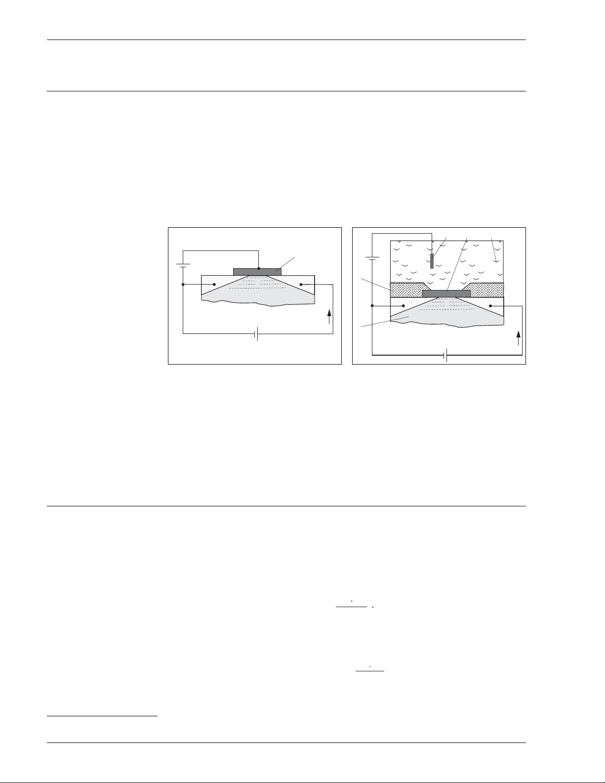
Function and system design
Measuring principle Ion-selective, or more generally ion-sensitive field effect transistors (ISFET) were developed in the 1970s as
an alternative to the glass electrode for pH measurement.
Basics
Ion-selective field effect transistors use an MOS
(pos. 1) is not a control electrode. Instead, the medium (see Fig 2, pos. 3) in the ISFET is in direct contact with
the gate isolator layer (pos. 2).Two strongly N-conducting areas are diffused in P-conducting substrate (see Fig
2, pos. 5) of the semiconductor material (Si). These N-conducting areas are current supplying ("Source", S) and
current accepting ("Drain", D) electrodes. The metallic gate electrode (in case of the MOSFET) resp. the
medium (in case of the ISFET) forms a capacitor with the substrate below. A potential difference between gate
and substrate (U
) causes a higher electron density between "Source" and "Drain". A N-conducting channel
GS
(pos. 2) is formed, i.e. a drain current (I
1)
) is induced.
D
transistor arrangement (see Fig 1) where the metallic gate
Fig. 1: Principle MOSFET
1 Metallic gate
2 N-conducting channel
With the ISFET, the medium is in direct contact with the gate isolator layer. Therefore, H
medium, which are located in the medium / gate isolator boundary layer, create the electric field (gate
potential). Depending on the effect described above, a N-conducting channel is formed and a current between
"Source" and "Drain" is induced. Suitable sensor circuits use the dependence on the ion-selective gate potential
to create an output signal proportional to the concentration of the ion type.
pH selective IsFET The gate isolator serves as an ion-selective layer for H
well (isolator effect) but allows reversible surface reactions with the H
Depending on the acidic or alkaline character of the measurement solutions, functional groups in the isolator
surface accept or reject H
+
ions (amphoteric character of the functional groups). This leads to a positive (H+
acceptance in the acidic medium) or negative (H
surface. Depending on the pH value, a defined surface charge can be used to control the field effect in the
channel between "Source" and "Drain".The processes which lead to the creation of a charge potential and
therefore to a control voltage U
UGS ...
U
R ...
T ...
n ...
Potential between gate and source
...
Offset voltage
0
Gas constant (8.3143 J/molK)
Temperature [K]
electrochemical valueability (1/mol)
between "Gate" and "Source" are described with the Nernst equation:
GS
a0003855
Fig. 2: Principle ISFET
1 Reference electrode
2 N-conducting channel
3 Gate isolator layer
4 Medium
5 P-doped silicon substrate
6 Sensor shaft
+
ions available in the
+
ions. The gate isolator is impermeable to the ions as
+
rejection in the alkaline medium) charging of the isolator
F ...
...
a
ion
+
ions.
Faraday constant (26.803 Ah)
Activity of ion kind (H+)
Nernst factor
a0003856
1) Metal Oxide Semiconductor
2 Endress+Hauser
At 25 °C (77 °F), the Nernst factor is –59.16 mV/pH.
Page 3
Tophit CPS491/CPS491D
pH (25 °C)
ΔpH
1 M NaOH1 M HCl
E+H ISFET
pH 1 … 13
Glass 1
Glass 2
-0.2
0.0
0.2
0.4
0.6
0.8
Important characteristics of
Tophit CPS491
• Resistance to breaking
This is the most obvious feature of the sensor. The complete sensor technology is embedded in a PEEK shaft.
Only the highly resistant isolator layer and the reference have direct contact with the medium.
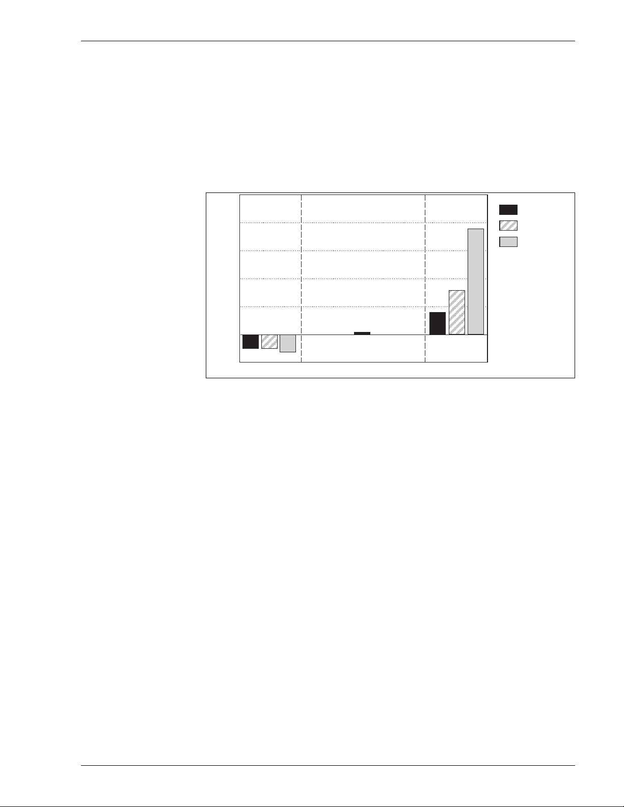
• Acid or alkaline errors
A further, important benefit compared with the glass electrode is the considerably reduced number of acid
or alkaline errors in extreme pH ranges. In contrast to glass electrodes, practically no foreign ions can build
up at the ISFET gate. The measuring error of < 0.01 pH (between pH 1 and 13) at 25°C (77 °F) is near by
the detection limit.
The figure below shows the acid or alkaline error of the ISFET between pH 1 and 13 and the comparison to
the glass electrode (two different pH glasses) at pH values 0.09 and 13.86.
Fig. 3: Comparison of acid and alkaline errors
a0003867-en
• Measurement stability and sensor response time
The ISFET response times are very short over the whole temperature range.
With the ISFET sensor, there is no (temperature-dependent) equilibrium setting as in the source layer of a
pH glass of a glass electrode. They can also be used at low temperatures without a deceleration in response
time.Large and fast temperature and pH value fluctuations have a smaller effect on the measuring error
(hysteresis) than with a glass electrode, as there is no stress exerted on the pH glass.
• Reference system
The integrated reference electrode of the sensor is a double-chamber reference system with a bridge
electrolyte. The benefits are an efficient and stable contact between the diaphragm and the reference lead,
and the extremely long poisoning path. The bridge electrolyte is highly resistant to temperature and pressure
changes.
Endress+Hauser 3
Page 4
Tophit CPS491/CPS491D
500
300
100
-100
-300
-500
0246 8101214
pH
mV
a
b
c
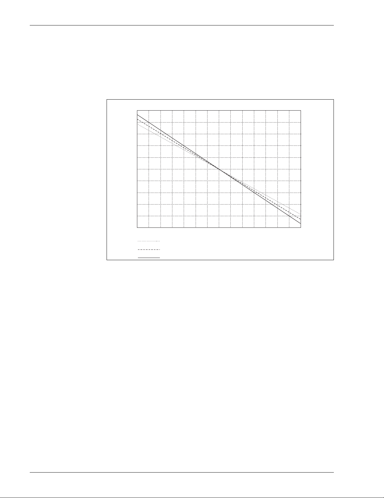
• Isothermic curves
– The Nernst equation defines the dependence of the measuring voltage on the hydrogen ion content (pH
value) and the temperature. It is the basis of pH measuring technology and for ISFET sensors too. A
temperature-dependent value for the potential change per pH value can be worked out from this equation
(isothermic curve, potential change per pH value at a defined temperature).
– The isothermic curves of the ISFET sensor are very close to the theoretical values (see Fig 4). This is further
proof for the high pH measurement precision of the sensor.
Fig. 4: Isothermic curves
a0003868-de
a Isothermic curve at 8 °C (46 °F), slope –55.8 mV/pH
b Isothermic curve at 37 °C (99 °F), slope –61.5 mV/pH
c Isothermic curve at 61 °C (142 °F), slope –66.3 mV/pH
4 Endress+Hauser
Page 5

Tophit CPS491/CPS491D
Memosens (CPS491D) Maximum process safety
The inductive and non-contacting measured value transmission of Memosens guarantees maximum process
safety and offers the following benefits:
• All problems caused by moisture are eliminated.
– The plug-in connection is free from corrosion.
– Measured value distortion from moisture is not possible.
– The plug-in system can even be connected under water.
• The transmitter is galvanically decoupled from the medium. The result: No more need to ask about
"symmetrically high-impedance" or "unsymmetrical" (for pH/ORP measurement) or an impedance
converter.
• EMC safety is guaranteed by screening measures for the digital measured value transmission.
• Application in explosion-hazardous areas is unproblematic; the integrated electronics are intrinsically safe.
Data safety through digital data transfer
The Memosens technology digitalizes the measured values in the sensor and transfers them to the transmitter
contactlessly and free from interference potential. The result:
• An automatic error message is generated if the sensor fails or the connection between sensor and transmitter
is interrupted.
• The availability of the measuring point is dramatically increased by immediate error detection.
Easy handling
Sensors with Memosens technology have integrated electronics that allow for saving calibration data and
further information such as total hours of operation and operating hours under extreme measuring conditions.
When the sensor is mounted, the calibration data are automatically transferred to the transmitter and used to
calculate the current measured value. Storing the calibration data in the sensor allows for calibration away from
the measuring point. The result:
• Sensors can be calibrated under optimum external conditions in the measuring lab. Wind and weather do
neither affect the calibration quality nor the operator.
• The measuring point availability is dramatically increased by the quick and easy replacement of precalibrated
sensors.
• The transmitter does not need to be installed close to the measuring point but can be placed in the control
room.
• Maintenance intervals can be defined based on all stored sensor load and calibration data and predictive
maintenance is possible.
• The sensor history can be documented on external data carriers and evaluation programs at any time. Thus,
the current application of the sensors can be made to depend on their previous history.
Communication with the transmitter
Always connect digital sensors to a transmitter with Memosens technology. Data transmission to a transmitter
for analog sensors is not possible.
The sensor is connected to the cable connection (CYK10) without contact. The power and data are transferred
inductively
Once connected to the transmitter, the data saved in the sensor are read digitally. You can call up these data
using the corresponding DIAG menu.
Data that digital sensors save include the following:
• Manufacturer data
– Serial number
–Order code
– Date of manufacture
• Calibration data
–Calibration date
– Calibration values
– Number of calibrations
– Serial number of the transmitter used to perform the last calibration
• Operational data
– Date of commissioning
– Hours of operation under extreme conditions
– Number of sterilizations
– Data for sensor monitoring.
Endress+Hauser 5
Page 6

Measuring system The complete measuring system comprises at least:
1
2
3
4
5
6
7
8
9
10
11
MEAS CAL
DIAG PARAM
PARAM
?
zone 1
zone 0/1
Atex zone Non-Ex
•ISFET sensor Tophit
• Measuring cable CPK12 (analog, with TOP68 connection) or CYK10 (digital, with Memosens)
• Transmitter, e.g. Liquiline CM4x, Liquisys CPM223 (for panel mounting) or Liquisys CPM253 (field
instrument) or Mycom CPM153.
•Assembly
– Immersion assembly, e.g. Dipfit CPA111
– Flow assembly, e.g. Flowfit CPA250
– Retractable assembly, e.g. Cleanfit CPA471
(CPA450 only with CPS471D, CPS491D or special versions CPS471-ESA and CPS491-ESA, --> Ordering
information)
– Fixed installation assembly, e.g. Unifit CPA442
There are additional accessories available depending on the application:
• Topclean CPC30 or Topcal CPC310 automatic cleaning system
• Extension cable, VBA, VBM or RM junction box
Chemicals and process (Ex applications)
Tophit CPS491/CPS491D
Fig. 5: Measuring system with fully automatic measuring, cleaning and calibration system Topcal
1
Tophit
2
Cleanfit CPA475
3
Mycom CPM153
4
Power supply
Process sterilizibility is no problem due to the wide range of applications for the ISFET pH sensor, not only
5
Control unit CPG310
6
Cleaner, buffer solutions
7
Steam, water, cleaner
8
Rinse block
9
Power cable
10
Compressed air
11
Liquids / cleaner
a0003880-en
relating to temperature but also to pH. There is only a small range of high pH values connected with high
temperatures where the sensor is not constantly stable (see "Process"). Media with these characteristics remove
the isolator oxide from the ISFET chip. As this is the pH and temperature range of CIP cleaning media, the
ISFET pH sensor should only be used in combination with an automatic retractable assembly.
Benefits of the Topcal fully automatic measurement, cleaning and calibration system:
• CIP cleaning
The sensor built into the retractable assembly is automatically "moved" out of the medium before cleaning.
In the rinse chamber of the retractable assembly the sensor is cleaned with suitable cleaning solutions.
• Calibration cycles can individually be set.
• Low maintenance costs due to fully automatic cleaning and calibration functions.
• Measuring results are optimally reproducable and the individual value tolerances are very low due to the
automatic calibration.
6 Endress+Hauser
Page 7

Tophit CPS491/CPS491D
1
2
3
4
RD
GN
Coaxial shield
WH
Coaxial cable
YE
BN
Shield
DRN
SRC (pH)
Source
Drain
Pt 1000
Pt 1000
Reference
Pt 1000
PM
GND
Water and wastewater
Fig. 6: Measuring system for water and wastewater applications
1 Tophit
2 Immersion assembly Dipfit CPA111
3 Special measuring cable CPK12 or CYK10
4 Transmitter Liquiline
Input
Measured variable pH value
Temperature
Measuring range 0 to 14 pH
–15 to 110 °C (5 to 230 °F)
Caution!
Note the process operating conditions.
Power supply
Electrical connection CPS491 The sensor is connected to the measuring transmitter using the special measuring cable CPK12.
a0003875
Endress+Hauser 7
Fig. 7: Special measuring cable CPK12
Note!
• The cable cors Yellow and White are connected on the sensor side.
a0003887-en
Page 8

Tophit CPS491/CPS491D
GN/YE
YE
GN
BN
WH
GND
+
–
Com A
Com B
GY
advised angle of installation
permissible with respect to
the application specific
conditions
• Make sure you comply with the instructions for connecting the sensor (wiring diagram) in the Operating
Instructions of the transmitter. The transmitter has to be appropriate for the use of ISFET sensors (e.g.
Liquiline CM42, Mycom CPM153 or Liquisys CPM223/253-IS).
A transmitter with only a standard pH input is inappropriate.
Electrical connection
The sensor is electrically connected to the transmitter by means of the special measuring cable CYK10.
CPS491D
Special measuring cable CYK10
a0003350
Performance characteristics
Response time < 5 s
for buffer change from pH 4 to pH 7 under reference operating conditions
Note!
The response of the integrated temperature sensor can be slower with extreme temperature changes.
Reference operating
conditions
Maximum measured error
Repeatability ± 0.1 % of measuring range
Start-up drift Everytime when switching on the measuring device a control loop is set up. During this time the measured
Reference temperature: 25 °C (77 °F)
Reference pressure: 1013 mbar (15 psi)
pH: ± 0.2 % of measuring range
Temperature: Class B acc. to DIN IEC 60751
value moves to the true value.
The settling time depends on the kind of interruption and the interruption time:
• Supply voltage interruption, sensor left in medium: approx. 3 to 5 minutes
• Interruption of the fluid film between pH sensitive ISFET and reference lead: approx. 5 to 8 minutes
• Longer dry storage of the sensor: up to 30 minutes
Installation
Installation angle ISFET sensors can be installed in any position, as there is no liquid internal lead. However, in case of an
overhead installation, a possible air cushion
between the medium and the diaphragm.
Fig. 8: Angle of installation
2) The sensor is delivered without air cushions. Air cushion formation is possible in case of working with vacuum, e.g. cleaning out of tanks.
8 Endress+Hauser
2)
in the reference system might interrupt the electrical contact
a0003897-en
Page 9

Tophit CPS491/CPS491D
z
y
1
2
z
y
08156767
08156768
30...45 °
x
z
y
1
3
5
4
Note!
• The installed sensor may be held under dry conditions for maximum 6 hours (also applies to overhead
installation).
• Make sure you comply with the instructions in the operating instructions for the assembly used.
Sensor orientation When installing the sensor, note the flow-past direction of the medium. The ISFET chip should be fixed at an
angle of approx 45° to the flow-past direction (see Fig 10). Fixing at the correct angle is very easy because of
the rotable plug-in head.
Fig. 9: Sensor orientation, front view
1 Serial number
2 Nameplate
a0003893
Fig. 10: Sensor orientation, 3d view
1 Serial number
3 rotable part of the connection head
a0003891
4 Medium flow-past direction
5 ISFET chip
When installing the sensor in an assembly, use the engraved serial number on the connection head for correct
sensor orientation. The serial number is always located in the same plane as the ISFET chip and the nameplate
(z-y-direction, see Fig 9).
Note!
ISFET sensors are not designed for the use in abrasive media. If you use them in such applications anyhow, you
must avoid direct flow against the chip. This considerably lengthens the service life and improves the drift
behavior of the sensor. You have however the disadvantage that the display of the pH value is not stable.
Environment
Ambient temperature range Caution!
Danger of frost damage
Do not operate the sensor at temperatures below –15°C (5 °F).
Storage temperature 0 to 50 °C (32 to 120 °F)
Endress+Hauser 9
Page 10

Tophit CPS491/CPS491D
120
100
80
60
40
20
0
024 6 81012
°C
14
pH
248
212
176
140
104
68
32
°F
Restricted
lifetime!
application range
ISFET
3
100
110
°C
°F
psi
145
212
230
43.5
10
bar
ISFET application range
bar
Ingress protection TOP68:
• IP 68 [1 m (3.3 ft) water column, 50 °C (122 °F), 168 h], autoclavable up to 135 °C (275 °F)
Memosens:
• IP 68 (10 m (32.8) ft water column, 25 °C (77 °F), 45 d, 1M KCl), autoclavable up to 135 °C (275 °F)
Sensitivity to light As every semiconductor the ISFET is light-sensitive (fluctuations of measured value). Avoid direct sunlight
during calibration and operation!
Normal environment light does not influence the measurement.
Process
Medium temperature
depending on pH
Application at low
temperatures
Pressure-temperature
diagram
At high temperatures over a long period of time, alkalis irreversibly destroy the gate isolator oxide.The sensor
can only be used in the indicated range (see Fig 11) at a cost to its life span. If it is constantly subjected to the
effects of a 2% sodium hydroxide solution at 80°C (176 °F), the sensor life span drops to approx. 10-15 hours.
a0003899-en
Fig. 11: Temperature and pH
Application range of the sensor according to the order code (see ordering information, product structure)
Max. 10 bar / 100 °C (145 psi / 212 °F), 3 bar / 110 °C (44 psi / 230 °F)
Fig. 12: Pressure-temperature diagram
Caution!
Danger of damage to the sensor
Never use the Tophit for applications outside the given specifications!
10 Endress+Hauser
a0003902-en
Page 11

Tophit CPS491/CPS491D
1
2
3
4
12
(0.47)
12
(0.47)
mm
(inch)
120 / 225 /
360 / 425 *
(4.72 / 8.86 /
14.2 / 16.7)
120 / 225 /
360 / 425 *
(4.72 / 8.86 /
14.2 / 16.7)
4
5
3
Recommended cleaning Depending on the degree of pollution:
• Hot water / soap (to be preferred)
• Isopropanole
• Chlorine cleaner
• Storing in KCl solution
Mechanical construction
Design, dimensions
Fig. 13: Tophit CPS491
* depending on the sensor version
a0003903
Weight 0.1 to 0.5 kg (0.2 to 1.1 lbs), depending on the sensor version
Material
Sensor shaft PEEK, FDA conform
Seals Perfluoroelastomer
Process connection Pg 13.5
Surface roughness R
< 0.8 μm (31.5 μin)
a
Temperature sensor Pt 1000 (class B acc. to DIN IEC 60751)
Plug-in head CPS491:
• ESB; TOP68, rotatable
CPS491D:
• Memosens, rotatable
Diaphragm Open aperture
Fig. 14: Sensor head
a0003904
1 Plug-in head
2 Sensor shaft
3 Reference electrode
4 ISFET chip
5 Seal (perfluoroelastomer)
Endress+Hauser 11
Page 12

Ordering information
PEEK ISFET sensor for glass free pH measurement
• For media with high dirt loads, also with organic solvents content
• Integrated Pt 1000 temperature sensor
• Double chamber reference system with poisoning resistant gel
•Open aperture
• Sealing material: Perfluoro elastomer
• Application range: pH 0 to 14, –15 to 110 °C (5 to 230 °F)
• For Ex and Non-Ex applications
Tophit CPS491/CPS491D
Product structure CPS491
Product structure CPS491D
Shaft length
2 120 mm (4.72 in)
4 225 mm (8.86 in)
5 360 mm (14.2 in)
6 425 mm (16.7 in)
Plug-in head
ESB Threaded plug-in head, Pg 13.5, TOP68 rotatable
Options
2 Chip sealing: Perfluoro elastomer
CPS491- complete order code
Version
7 Basic version
Shaft length
2 120 mm (4.72 in)
4 225 mm (8.86 in)
5 360 mm (14.2 in)
6 425 mm (16.7 in)
Additional option
2 Perfluoro elastomer
Approval
G ATEX II 1G Ex ia IIC T4/T6, FM/CSA IS/NI Cl I DIV 1&2 GP A-D
1 Non-hazardous location
CPS491D- complete order code
Special version CPS491-ESA
•Open aperture
• Chip sealing: perfluorelastomer
• 120 mm (4.72 inch)
• TOP68 / ESA plug-in head
• Order no.: 51512562
Certificates and approvals
Ex approval FM/CSA •FM
IS/NI Cl I DIV 1&2 GP A-D, associated apparatus Mycom 153-O/-P or Liquiline CM42-*P
•CSA
IS/NI Cl I DIV 1&2 GP A-D, associated apparatus Mycom 153-S or Liquiline CM42-*S
Ex approval ATEX Device group II, Category 1G
Explosion protection Ex ia IIC T4/T6
12 Endress+Hauser
Page 13

Tophit CPS491/CPS491D
Accessories
Note!
In the following sections, you find the accessories available at the time of issue of this documentation.
For information on accessories that are not listed here, please contact your local service or sales representation.
Transmitters Liquiline CM42
• Modular two-wire transmitter, stainless steel or plastic, field or panel instrument
• Various Ex approvals (ATEX, FM, CSA, Nepsi, TIIS)
• HART, PROFIBUS or FOUNDATION Fieldbus available
• Ordering acc. to product structure, see Technical Information (TI381C/07/en)
Liquisys CPM223/253
• Transmitter for pH and ORP, field or panel-mounted housing
• HART or PROFIBUS available
• Ordering acc. to product structure, see Technical Information (TI194C/07/en)
Mycom CPM153
• Transmitter for pH and ORP, one or two channel version, Ex or non-Ex
• HART or PROFIBUS available
• Ordering acc. to product structure, see Technical Information (TI233C/07/en)
Fully automatic measuring
systems
Service tool Memocheck Plus CYP01D, Memocheck CYP02D
Assemblies (selection) Dipfit CPA111
Topcal CPC310
• Fully automatic measuring, cleaning and calibration system; Ex or non-Ex
• In-situ cleaning and calibration, automatic sensor monitoring
• Ordering acc. to product structure, Technical Information TI404C/07/en
Topclean CPC30
• Fully automatic measuring and cleaning system; Ex or non-Ex
• In-situ cleaning, automatic sensor monitoring
• Ordering acc. to product structure, see Technical Information TI235C/07/en
• Tool for the qualification of measuring chains
• Service tool for quick, on-site checks of measuring systems with Memosens technology
• Verification of data transmission
• Ordering acc. to product structure, KA399C/07/a2
• Immersion and installation assembly for open and closed tanks
• Technical Information TI112C/07/en
Flowfit CPA250
• Flow assembly for installation in pipework
• Technical Information TI041C/07/en
Cleanfit CPA471
• Retractable assembly for tank and pipe installation
• Technical Information TI217C/07/en
Cleanfit CPA450
• Manual retractable assembly for installing 120 mm sensors in tanks and pipework
• Technical Information TI183C/07/en
Unifit CPA442
• Installation assembly for food, biotechnology and pharmaceuticals, with EHEDG and 3A certificate
• Technical Information TI306C/07/en
Note!
Ordering of assemblies is acc. to product structure. Please refer to the corresponding Technical Information.
Endress+Hauser 13
Page 14

Buffer solutions High-quality buffer solutions of Endress+Hauser - CPY20
The secondary buffer solutions have been referenced to primary reference material of the PTB (German Federal
Physico-technical Institute) and to standard reference material of NIST (National Institute of Standards and
Technology) according to DIN 19266 by a DKD (German Calibration Service) accredited laboratory.
pH value
A pH 2.00 (accuracy ± 0.02 pH)
C pH 4.00 (accuracy ± 0.02 pH)
E pH 7.00 (accuracy ± 0.02 pH)
G pH 9.00 (accuracy ± 0.02 pH)
I pH 9.20 (accuracy ± 0.02 pH)
K pH 10.00 (accuracy ± 0.05 pH)
M pH 12.00 (accuracy ± 0.05 pH)
Quantity
01 20 x 18 ml (0.68 fl.oz) only buffer solutions pH 4.00 and 7.00
02 250 ml (8.45 fl.oz)
10 1000 ml (0.26 US gal)
50 5000 ml (1.32 US gal) canister for Topcal S
Certificates
A Buffer analysis certificate
Version
1Standard
CPY20- complete order code
Tophit CPS491/CPS491D
Cables CPK12 (TOP68)
Cable length
HA Cable length: 5 m (16.41 ft), TPE sheath, max. 130 °C (266 °F)
HB Cable length: 10 m (32.82 ft), TPE sheath, max. 130 °C (266 °F)
HC Cable length: 15 m (49.23 ft), TPE sheath, max. 130 °C (266 °F)
HD Cable length: 20 m (65.64 ft), TPE sheath, max. 130 °C (266 °F)
HF Cable length: 5 to 20 m (16.41 to 65.64 ft), TPE sheath, max. 130 °C (266 °F)
HG Cable length: 16 - 160 ft, TPE sheath, max. 130 °C (266 °F)
CPK12- complete order code
Version
AStandard version
Termination
1 End sleeve on device side, braided cable screening
Potential matching
A External potential matching with flat plug
14 Endress+Hauser
Page 15

Tophit CPS491/CPS491D
CYK10 (Memosens)
CYK10 Memosens data cable
• For digital sensors with Memosens technology
• Ordering according to product structure, see below
Certificates
A Standard, non-Ex
G ATEX II 1G Ex ia IIC T6/T4/T3, FM/CSA IS/NI Cl I DIV 1&2 GP A-D
L LABS free, non-Ex
O FM IS/NI Cl I DIV 1&2 GP A-D
S CSA IS/NI Cl I DIV 1&2 GP A-D
TTIIS
V ATEX/NEPSI II 3G Ex nL IIC
Cable length
03 Cable length: 3 m (9.8 ft)
05 Cable length: 5 m (16 ft)
10 Cable length: 10 m (33 ft)
15 Cable length: 15 m (49 ft)
20 Cable length: 20 m (66 ft)
25 Cable length: 25 m (82 ft)
88 ... m length
89 ... ft length
Ready-made
1Wire terminals
2 M12 plug
CYK10- complete order code
Note!
Ex versions of CYK10 are indicated by an orange-red coupling end.
Cable extension CYK12
CYK12 measuring cable
• Non-terminated cable for extension of sensor cables, used in combination with CPK1, CPK9 and CPK12
• Coax and 5 pilot wires
• Sold by the meter:
– Non-Ex version, black: order no. 51506598
– Ex-version, blue: order no. 51506616
CYK81
CYK81 measuring cable
• Non-terminated measuring cable for extension of sensor cables of e.g. Memosens sensors, CUS31/CUS41
• 2 wires, twisted pair with shield and PVC-sheath (2 x 2 x 0.5 mm
• Sold by the meter, order no.: 51502543
2
+ shield)
Endress+Hauser 15
Page 16

Junction boxes
United States
Endress+Hauser, Inc.
2350 Endress Place
Greenwood, IN 46143
Tel. 317-535-7138
Sales 888-ENDRESS
888-363-7377
Service 800-642-8737
fax 317-535-8498
inquiry@us.endress.com
www.us.endress.com
TI377C/24/en/05.10
© 2010 Endress+Hauser, Inc.
Canada
Endress+Hauser Canada
1075 Sutton Drive
Burlington, ON L7L 5Z8
Tel. 905-681-9292
800-668-3199
Fax 905-681-9444
info@ca.endress.com
www.ca.endress.com
Mexico
Endress+Hauser, México, S.A. de C.V.
Fernando Montes de Oca 21 Edificio A Piso 3
Fracc. Industrial San Nicolás
54030. Tlalnepantla de Baz
Estado de México
México
Tel: +52 55 5321 2080
Fax +52 55 5321 2099
eh.mexico@mx.endress.com
www.mx.endress.com
Junction box VBA
• For cable extension of pH/ORP sensors
• 10 terminals, protection class: IP 65 (i NEMA 4X)
• Cable entries: 2 x Pg 13.5, 2 x Pg 16
• Material: polycarbonate
• Order no.: 50005276
Junction box RM
• For cable extension (e.g. for Memosens sensors or CUS31/CUS41)
•5 terminals
• Cable entries: 2 x Pg 13.5
•Material: PC
• Ingress protection: IP 65 (i NEMA 4X)
• Order no.: 51500832
Junction box VBM
• For cable extension
•10 terminals
• Cable entries: 2 x Pg 13.5 or 2 x NPT ½"
• Material: aluminum
• Ingress protection: IP 65 (i NEMA 4X)
• Order numbers:
– cable entries Pg 13.5: 50003987
– cable entries NPT ½": 51500177
Tophit CPS491/CPS491D
16 Endress+Hauser
 Loading...