

Endress+Hauser CPA871 Operating Manual
BA01323C/07/EN/05.19
71439183
2019-04-30
Products Solutions Services
Operating Instructions
Cleanfit CPA871
Flexible retractable process assembly for water,
wastewater, chemical industry and heavy industry


Cleanfit CPA871 Table of contents
Table of contents
1 About this document ................ 4
1.1 Warnings ............................ 4
1.2 Symbols used .......................... 4
1.3 Symbols on the device ................... 4
2 Basic safety instructions ............ 5
2.1 Requirements for the personnel ............ 5
2.2 Designated use ........................ 5
2.3 Occupational safety ..................... 5
2.4 Operational safety ...................... 6
2.5 Product safety ......................... 6
3 Product description ................. 7
3.1 Product design ......................... 7
4 Incoming acceptance and product
identification ....................... 9
4.1 Incoming acceptance .................... 9
4.2 Scope of delivery ....................... 9
4.3 Product identification ................... 10
4.4 Certificates and approvals ............... 11
10.3 Flow vessel .......................... 55
10.4 Sensors ............................. 56
10.5 Absorption sensor ..................... 58
11 Technical data .................... 59
11.1 Environment ......................... 59
11.2 Process ............................. 59
11.3 Mechanical construction ................ 63
Index .................................. 64
5 Installation ....................... 12
5.1 Installation conditions .................. 12
5.2 Mounting the assembly ................. 18
5.3 Installing the sensor ................... 26
5.4 Post-installation check .................. 31
6 Commissioning .................... 32
7 Operation ......................... 33
7.1 Adapting the assembly to the process
conditions ........................... 33
8 Maintenance ...................... 36
8.1 Maintenance intervals .................. 36
8.2 Cleaning the assembly .................. 38
8.3 Cleaning the sensor .................... 38
8.4 Cleaning agent ....................... 39
8.5 Replacing seals ....................... 40
9 Repair ............................ 52
9.1 Spare parts .......................... 52
9.2 Return .............................. 52
9.3 Disposal ............................ 52
10 Accessories ....................... 53
10.1 Installation material for rinse connections ... 54
10.2 Cleaning systems ...................... 54
Endress+Hauser 3
About this document Cleanfit CPA871
1 About this document
1.1 Warnings
Structure of information Meaning
DANGER
L
Causes (/consequences)
If necessary, Consequences of
non-compliance (if applicable)
Corrective action
‣
WARNING
L
Causes (/consequences)
If necessary, Consequences of
non-compliance (if applicable)
Corrective action
‣
CAUTION
L
Causes (/consequences)
If necessary, Consequences of
non-compliance (if applicable)
Corrective action
‣
NOTICE
Cause/situation
If necessary, Consequences of
non-compliance (if applicable)
Action/note
‣
This symbol alerts you to a dangerous situation.
Failure to avoid the dangerous situation will result in a fatal or serious
injury.
This symbol alerts you to a dangerous situation.
Failure to avoid the dangerous situation can result in a fatal or serious
injury.
This symbol alerts you to a dangerous situation.
Failure to avoid this situation can result in minor or more serious injuries.
This symbol alerts you to situations which may result in damage to
property.
1.2 Symbols used
Symbol Meaning
Additional information, tips
Permitted or recommended
Not permitted or not recommended
Reference to device documentation
Reference to page
Reference to graphic
Result of a step
1.3 Symbols on the device
Symbol Meaning
Reference to device documentation
4 Endress+Hauser

Cleanfit CPA871 Basic safety instructions
2 Basic safety instructions
2.1 Requirements for the personnel
• Installation, commissioning, operation and maintenance of the measuring system may
be carried out only by specially trained technical personnel.
• The technical personnel must be authorized by the plant operator to carry out the
specified activities.
• The electrical connection may be performed only by an electrical technician.
• The technical personnel must have read and understood these Operating Instructions
and must follow the instructions contained therein.
• Faults at the measuring point may only be rectified by authorized and specially trained
personnel.
Repairs not described in the Operating Instructions provided must be carried out only
directly at the manufacturer's site or by the service organization.
2.2 Designated use
The Cleanfit CPA871 retractable assembly, which can be manually or pneumatically
operated, is designed for the installation of sensors in vessels and pipes.
Thanks to its design, it can be operated in pressurized systems (→ 59).
Use of the device for any purpose other than that described, poses a threat to the safety of
people and of the entire measuring system and is therefore not permitted.
The manufacturer is not liable for damage caused by improper or non-designated use.
2.2.1 Use in explosion-proof areas
As a manufacturer of products used for analysis, we declare that the product supplied has
undergone an ignition risk assessment and may be used in hazardous atmospheres once
the following conditions for safe usage have been met:
• The protective ring is labeled as follows: "CAUTION, DANGER DUE TO ELECTROSTATIC
CHARGES, CLEAN USING ONLY AN ANTISTATIC CLOTH". This instruction must be
observed.
• Assemblies comprising wetted parts made of non-conductive material, must not be used
in potentially explosive atmospheres.
• The compressed air supply, sensors and limit position switches must comply with the
applicable guidelines and standards for use in hazardous atmospheres, be labeled with
the degree of protection and meet the requirements of the relevant range of application.
The ambient temperatures must be observed. The limit position switch used in the
product complies with this requirement.
• Ensure that the compressed air does not contain a potentially explosive atmosphere.
• Care must be taken to ensure that movements during insertion and retraction of the
sensor do not damage the connection.
• The product must be incorporated into the local potential equalization system.
• The Operating Instructions for the product and in particular the conditions for safe usage
must be read, understood and implemented.
The product does not need to be labeled with the degree of protection.
2.3 Occupational safety
As the user, you are responsible for complying with the following safety conditions:
• Installation guidelines
• Local standards and regulations
Endress+Hauser 5

Basic safety instructions Cleanfit CPA871
2.4 Operational safety
Before commissioning the entire measuring point:
1. Verify that all connections are correct.
2. Ensure that electrical cables and hose connections are undamaged.
3. Do not operate damaged products, and protect them against unintentional operation.
4. Label damaged products as defective.
During operation:
If faults cannot be rectified:
‣
products must be taken out of service and protected against unintentional operation.
2.5 Product safety
2.5.1 State of the art
The product is designed to meet state-of-the-art safety requirements, has been tested, and
left the factory in a condition in which it is safe to operate. The relevant regulations and
European standards have been observed.
6 Endress+Hauser
Cleanfit CPA871 Product description
1
2
3
4
5
6
7
8
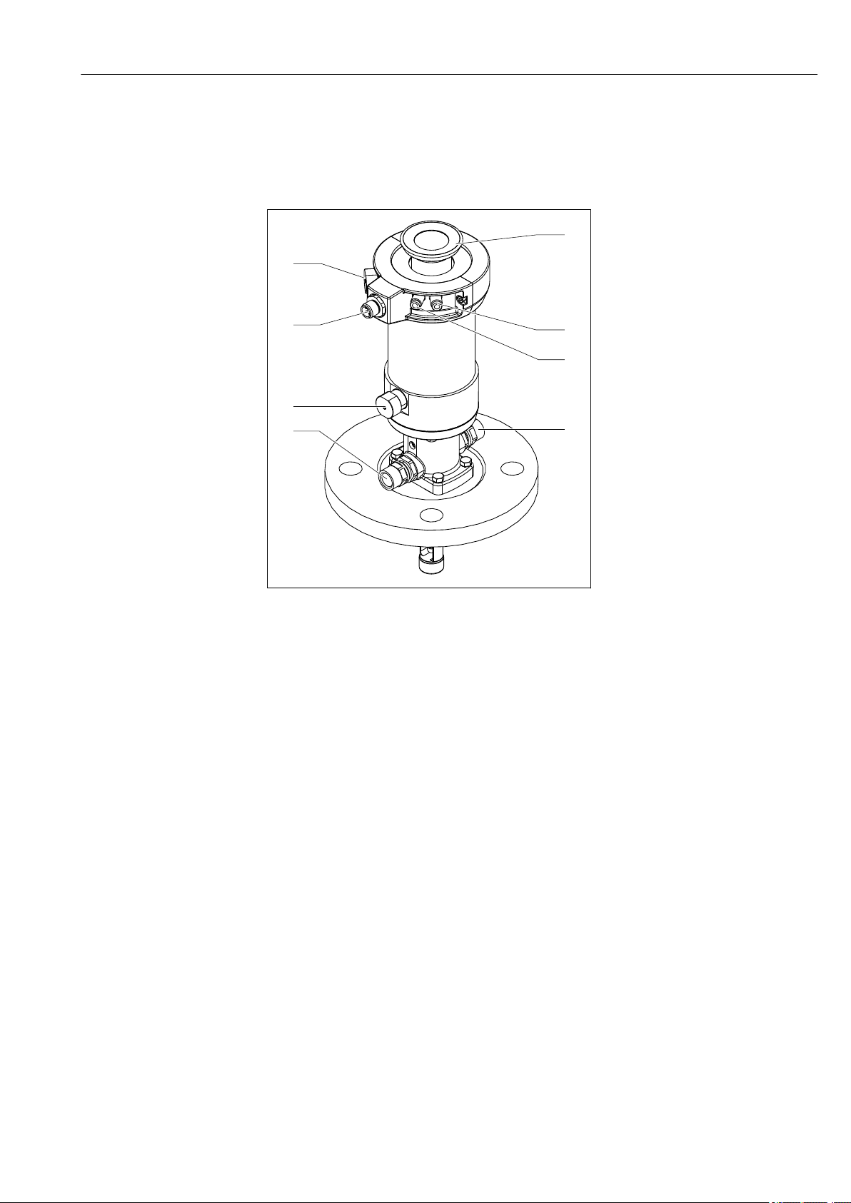
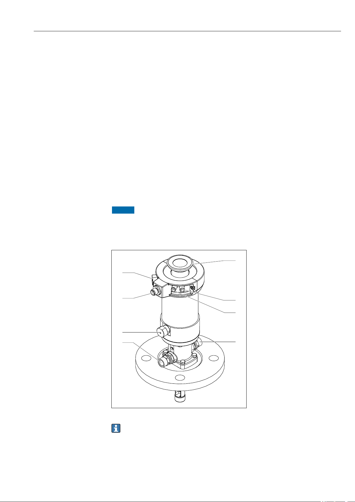
3 Product description
3.1 Product design
1 Rinse connection (outlet)
2 Automatic limit position lock,
process
3 Connection for limit position
switch
4 Automatic limit position lock,
service
5 Fastening ring for protective
cover
6 Pneumatic connection (move
to measuring position)
7 Pneumatic connection (move
to service position)
8 Rinse connection (inlet)
A0029614
1 Assembly with pneumatic drive (without protective cover)
Endress+Hauser 7
Product description Cleanfit CPA871
1
2
3
4
5
6
7
1
2
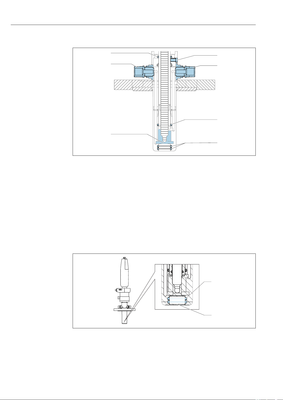
3.1.1 Operating principle
A0039361
2 Sealing system, assembly in service position
1 Rinse chamber, inlet
2 Seal, drive (1 x O-ring)
3 Leakage hole
4 Rinse chamber, outlet
5 Seal, rinse chamber (1 x O-ring)
6 Process seal (2 x O-ring)
7 Rinse chamber
The assembly is open to the process during insertion/retraction; the rinse connections
must either be pipe-fitted or sealed.
The assembly has a pin seal. This seals the assembly from the process in the relevant limit
position.
Process seal
3 Process seal, assembly in service position
1 Process seal (2 x O-ring)
2 Pin
A0039106
8 Endress+Hauser

Cleanfit CPA871 Incoming acceptance and product identification
4 Incoming acceptance and product
identification
4.1 Incoming acceptance
1. Verify that the packaging is undamaged.
Notify the supplier of any damage to the packaging.
Keep the damaged packaging until the issue has been resolved.
2. Verify that the contents are undamaged.
Notify the supplier of any damage to the delivery contents.
Keep the damaged goods until the issue has been resolved.
3. Check that the delivery is complete and nothing is missing.
Compare the shipping documents with your order.
4. Pack the product for storage and transportation in such a way that it is protected
against impact and moisture.
The original packaging offers the best protection.
Make sure to comply with the permitted ambient conditions.
If you have any questions, please contact your supplier or your local Sales Center.
4.2 Scope of delivery
The scope of delivery comprises:
• Ordered version of assembly
• Operating Instructions
• Adapter push connector 6 mm (0.24 in) of 4 mm (0.16 in) (outer diameter)
Endress+Hauser 9

Incoming acceptance and product identification Cleanfit CPA871
4.3 Product identification
4.3.1 Nameplate
The nameplate provides you with the following information on your device:
• Manufacturer identification
• Order code
• Extended order code
• Serial number
• Ambient and process conditions
• Safety information and warnings
Compare the information on the nameplate with the order.
‣
4.3.2 Product identification
The order code and serial number of your product can be found in the following locations:
• On the nameplate
• In the delivery papers
Obtaining information on the product
1. Go to www.endress.com.
2. Call up the site search (magnifying glass).
3. Enter a valid serial number.
4. Search.
The product structure is displayed in a popup window.
5. Click on the product image in the popup window.
A new window (Device Viewer) opens. All of the information relating to your
device is displayed in this window as well as the product documentation.
Product page
www.endress.com/CPA871
10 Endress+Hauser

Cleanfit CPA871 Incoming acceptance and product identification
4.4 Certificates and approvals
CRN
The design of the assembly was reviewed and registered by the Canadian safety authorities
for all Canadian provinces in accordance with the requirements of the "Canadian
Registration Number (CRN)" system.
ATEX- 2014/34/EU
The assembly does not fall within the scope of the directive. However, if conditions for safe
use are adhered to, it may be deployed in the hazardous area.
DRGL- 2014/68/EU / PED- 2014/68/EU
The assembly has been manufactured according to good engineering practice as per Article
4, Paragraph 3 of the Pressure Equipment Directive 2014/68/EU and is therefore not
required to bear the CE label.
Endress+Hauser 11

Installation Cleanfit CPA871
5 Installation
5.1 Installation conditions
5.1.1 Orientation
The assembly is designed for installation on tanks and pipes. Suitable process connections
must be available for this.
NOTICE
Frost damage to the assembly
If used outdoors, ensure that water cannot penetrate the drive.
‣
The assembly is designed in such a way that there are no restrictions with regard to the
orientation.
The sensor that is used can restrict the orientation.
Ensure compliance with the Operating Instructions of the sensor installed.
12 Endress+Hauser
Cleanfit CPA871 Installation
XP
XM/XS = 398/434 (15.67/17.09)
158 (6.22)
! 61
(2.40)
117
(4.61)
XA
63
(2.48)
19!
(0.47)
24
(0.9)
11,7
(4.6)
! 61
(2.40)
XA
! 61
(2.40)
107
(4.21)
42 (1.65)
63
(2.48)
XP
155 (6.10)
XM/XS = 398/434 (15.67/17.09)
19!
(0.47)
11,7
(4.6)
24
(0.9)
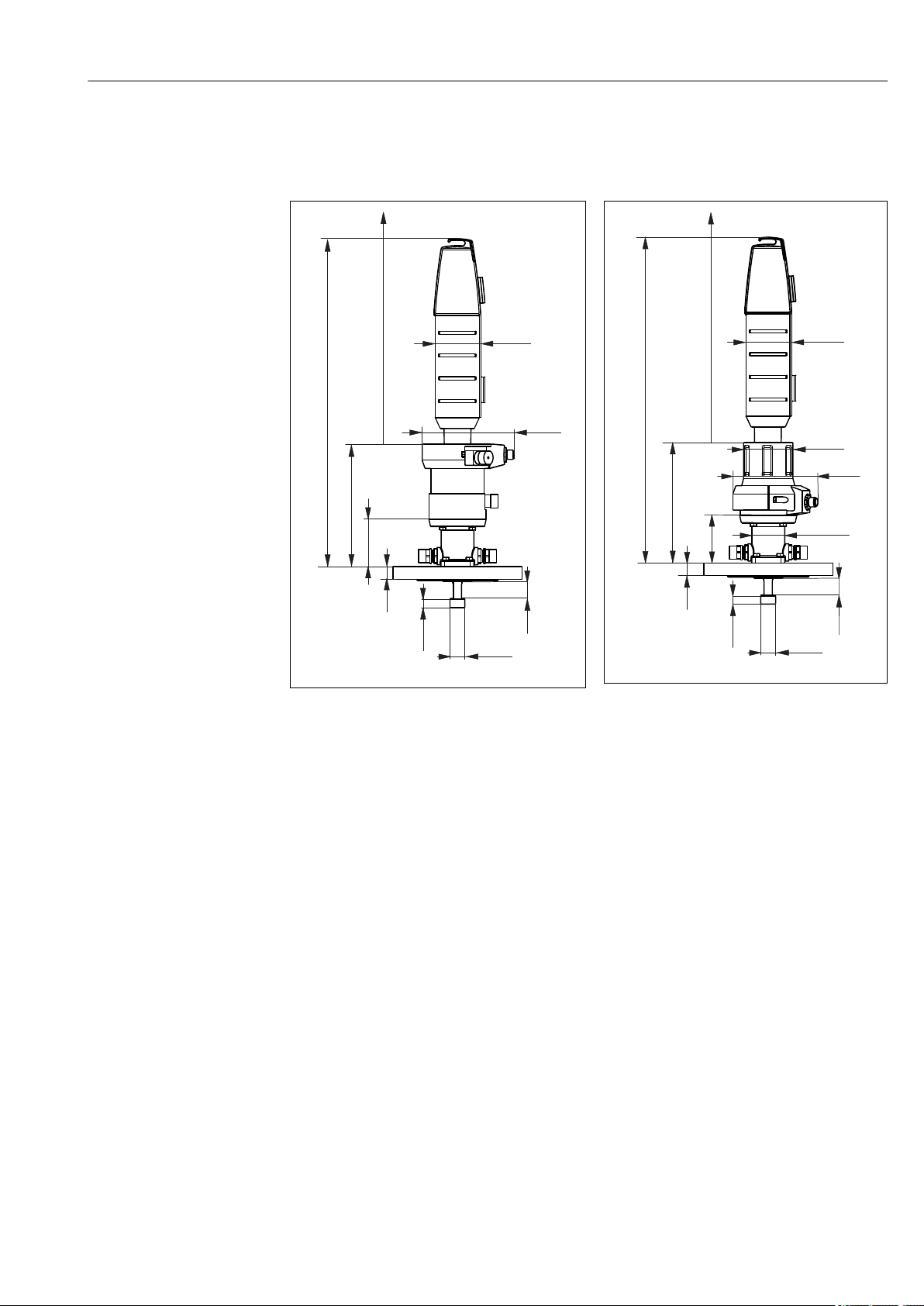
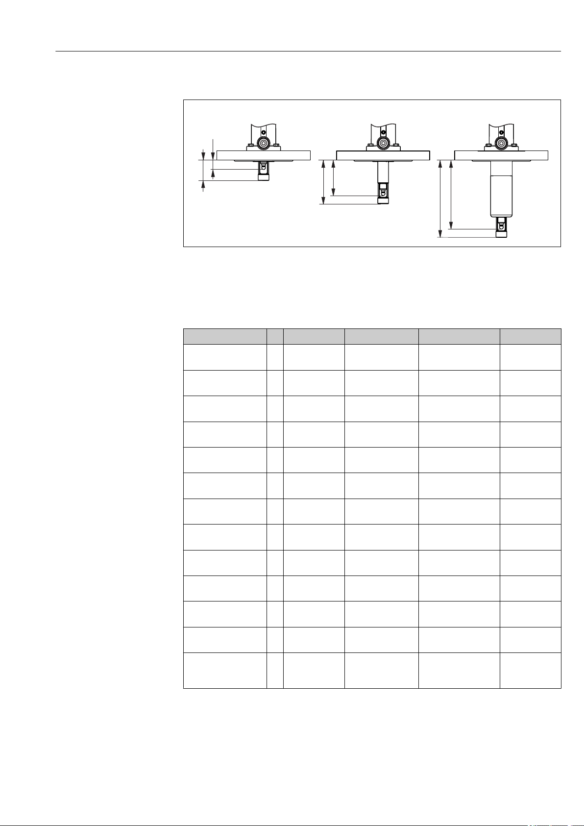
5.1.2 Dimensions
Short version
A0023894
4 Pneumatic drive, short version, dimensions in
mm (in)
XM
Assembly in measuring position
XS
Assembly in service position
XP
Height of particular process connection (see table below)
XA
Necessary mounting distance for sensor replacement
5 Manual drive, short version, dimensions in
mm (in)
The mounting distance XA is 280 mm (11.02") for 120 mm sensors
The mounting distance XA is 408 mm (15.94") for 225 mm sensors
A0023897
Endress+Hauser 13
Installation Cleanfit CPA871
! 61
(2.40)
XP
200 (7.87)
107
(4.21)
63
XM/XS = 440/518 (17.32/20.39)
XA
(2.48)
24
(0.9)
11,7
(4.6)
! 19
(0.7)
19!
(0.47)
! 61
(2.40)
! 61
(2.40)
107
(4.21)
42 (1.65)
63
(2.48)
XP
197 (7.76)
XM/XS = 440/518 (17.32/20.39)
XA
24
(0.9)
11,7
(4.6)
! 19
(0.7)
19!
(0.47)
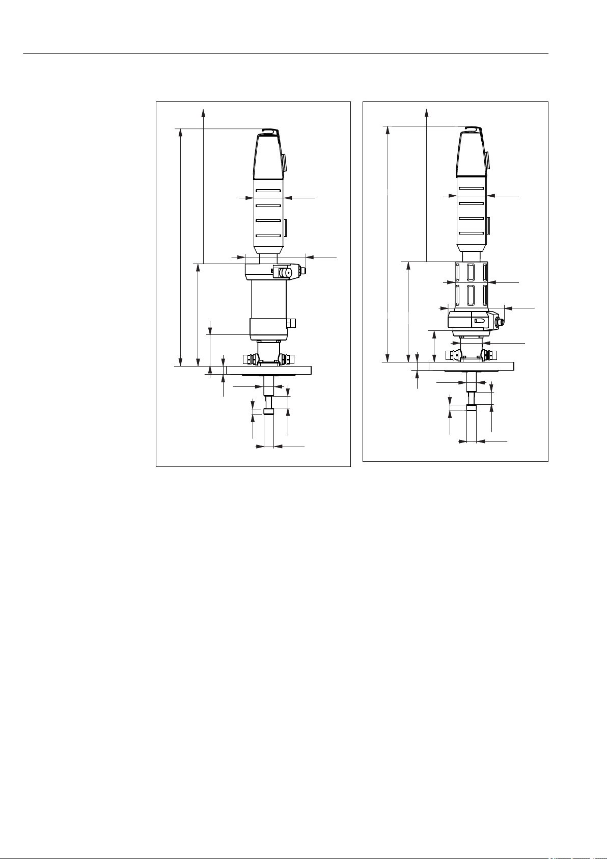
Long version
A0023895
6 Pneumatic drive, long version, dimensions in
mm (in)
XM
Assembly in measuring position
XS
Assembly in service position
XP
Height of particular process connection (see table below)
XA
Necessary mounting distance for sensor replacement
7 Manual drive, long version, dimensions in
mm (in)
The mounting distance XA is 360 mm (14.17") for 225 mm sensors
A0023898
14 Endress+Hauser
Cleanfit CPA871 Installation
! 61
(2.40)
117
(4.61)
158 (6.22)
63
XP
XM/XS = 398/434 (15.67/17.09)
XA
(2.48)
24
(0.9)
11,7
(4.6)
! 38
(1.5)
19!
(0.47)
XP
XM/XS = 398/434 (15.67/17.09)
155 (6.10)
! 61
(2.40)
107
(4.21)
42 (1.65)
63
(2.48)
! 61
(2.40)
XA
24
(0.9)
11,7
(4.6)
! 38
(1.5)
19!
(0.47)
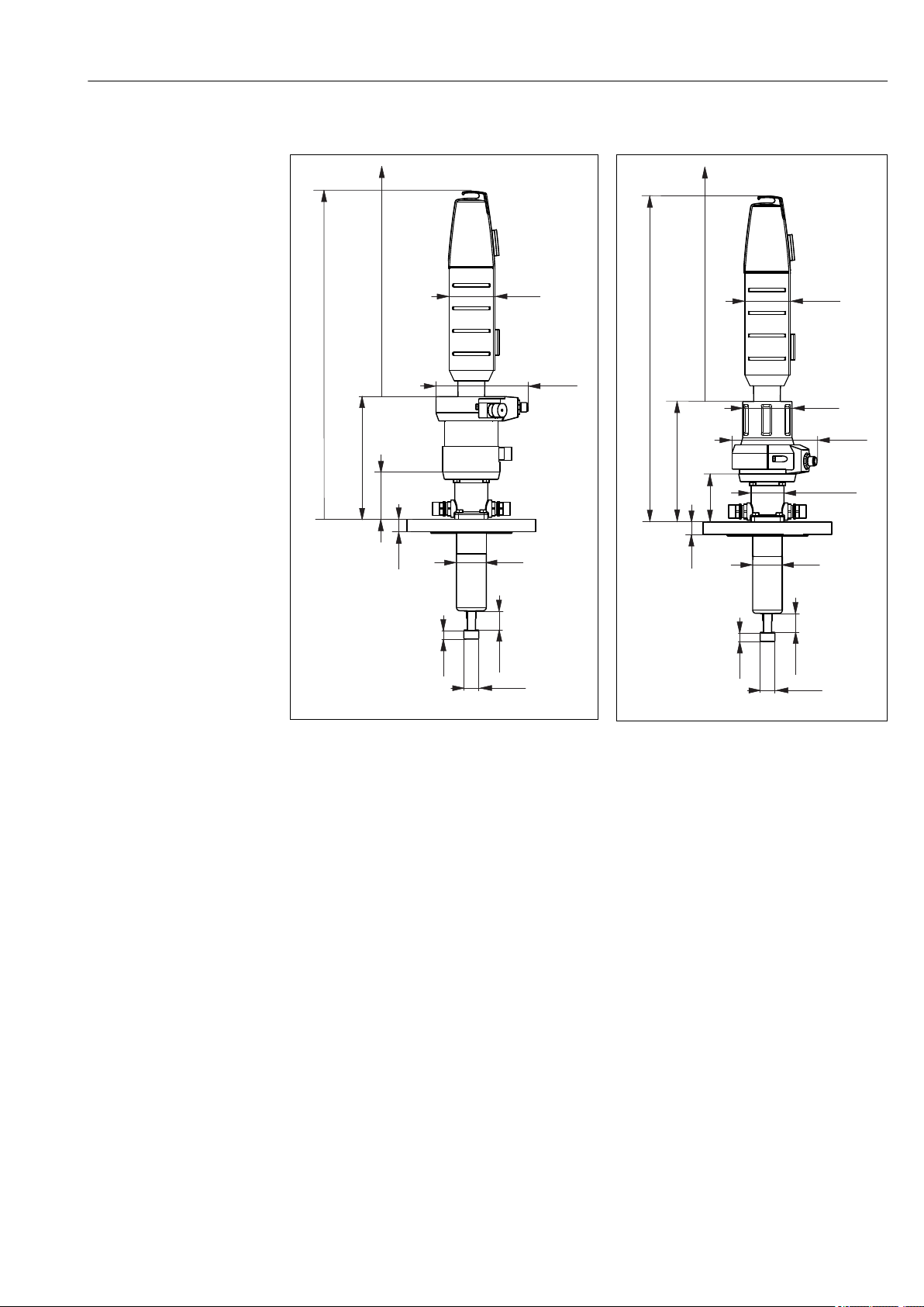
Immersion chamber version
A0023896
8 Immersion chamber version with pneumatic drive,
dimensions in mm (in)
XM
Assembly in measuring position
XS
Assembly in service position
XP
Height of particular process connection (see table below)
XA
Necessary mounting distance for sensor replacement
9 Immersion chamber version with manual
drive, dimensions in mm (in)
The mounting distance XA is 280 mm (11.02") for 225 mm sensors
The mounting distance XA is 570 mm (22.44") for 360 mm sensors
A0023899
Endress+Hauser 15
Installation Cleanfit CPA871
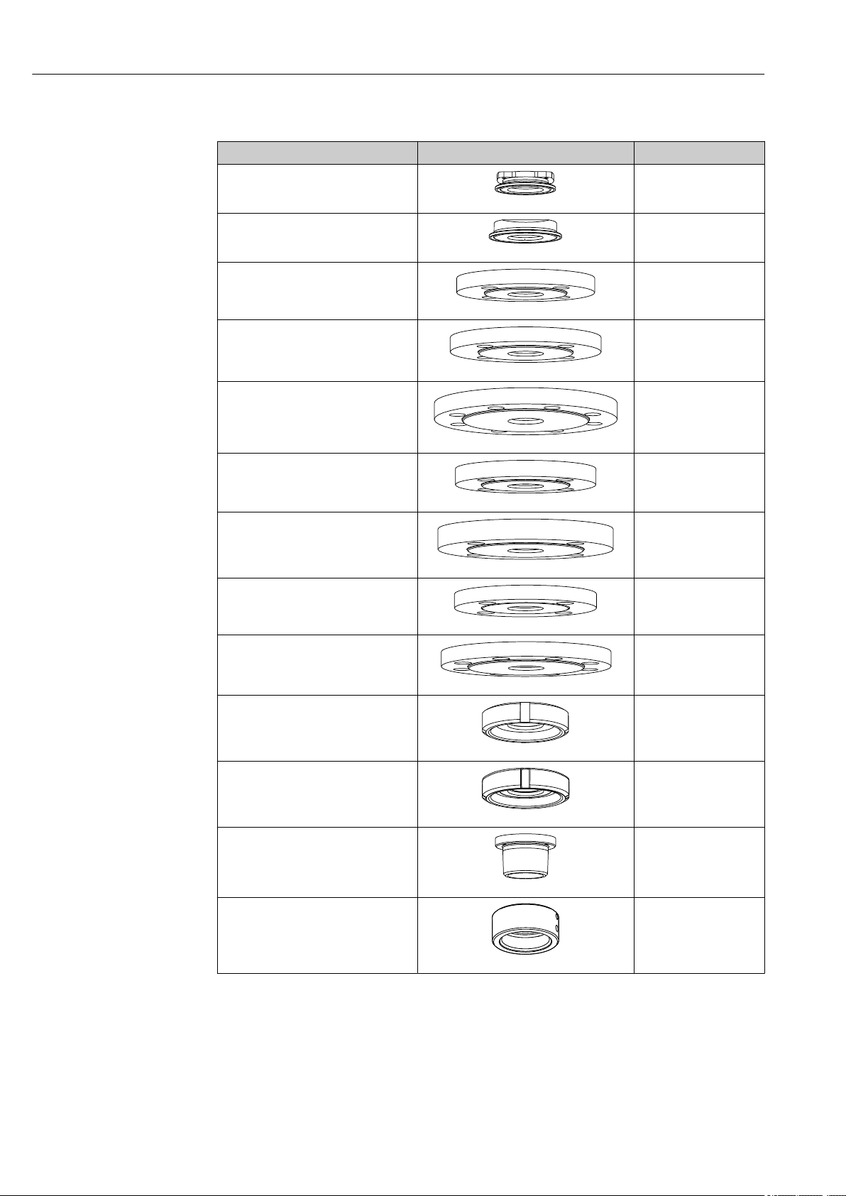
Process connection height
Process connection Height XP in mm (in)
CB Clamp 2"
ISO2852, ASME BPE-2012
CC Clamp 2½"
ISO2852, ASME BPE-2012
FA Flange DN 40 PN16, EN1092-1
FB Flange DN 50 PN16, EN1092-1
FC Flange DN 80 PN10, EN1092-1
FD Flange 2" 150 lbs, ASME B16.5
16 (0.63)
A0024100
16 (0.63)
A0024101
18 (0.71)
A0024102
18 (0.71)
A0024103
20 (0.79)
A0024104
19.1 (0.75)
FE Flange 3" 150 lbs, ASME B16.5
FF 10K50, JIS B2220
FG 10K80, JIS B2220
MA Dairy fitting DN 50 DIN 11851
MB Dairy fitting DN 65 DIN 11851
HB Thread NPT 1½"
NA
Thread ISO 228 G1¼
A0024105
23.8 (0.94)
A0024106
16 (0.63)
A0024107
18 (0.71)
A0024108
15.5 (0.61)
A0024109
15.5 (0.61)
A0024110
40.5 (1.57)
A0024111
31.1 (1.22)
A0039368
16 Endress+Hauser
Cleanfit CPA871 Installation
X1
X2
X1
X2
X1
X2
1 2
3/4
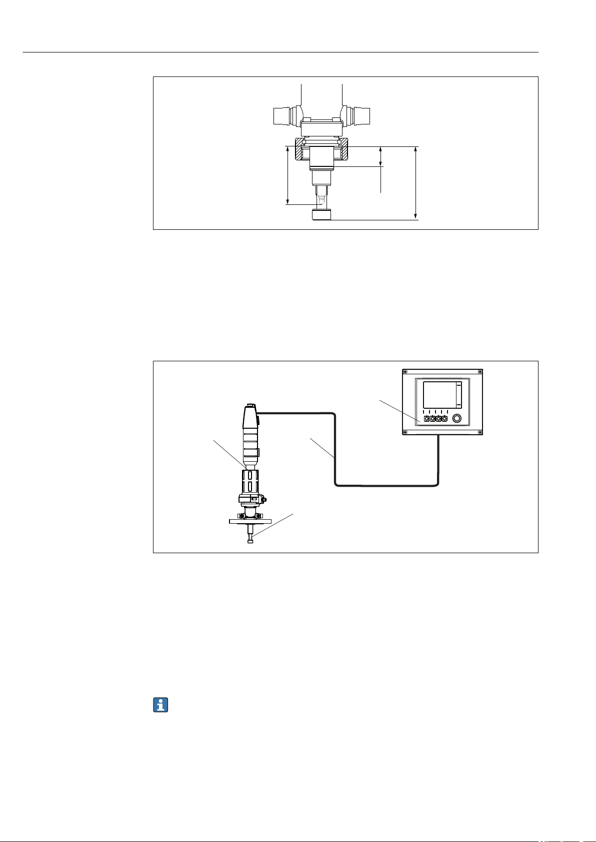
5.1.3 Immersion depths
A0023893
10 Immersion depths in mm (in)
1 Short stroke, 36 mm (1.42 in)
2 Long stroke, 78 mm (3.07 in)
3 Immersion version
Versions
Process connection 1 2 3 4
CB Clamp ISO2852
ASME BPE-2012 2"X1X2
CC Clamp ISO2852
ASME BPE-2012 2½"X1X2
FA Flange DN 40
EN1092-1
FB Flange DN 50
EN1092-1
FC Flange DN 80
EN1092-1
FD Flange 2" 150 lbs
ASME B16.5
FE Flange 3" 150 lbs
ASME B16.5
FF Flange 10K50
JIS B2220
FG Flange 10K80
JIS B2220
HB Thread NPT 1½" X1
MA Dairy fitting
DN 50 DIN 11851
MB Dairy fitting
DN 65 DIN 11851
NA Thread ISO 228
G 1¼
14.9 (0.59)
34.2 (1.35)
14.9 (0.59)
34.2 (1.35)
X1X214.9 (0.59)
34.2 (1.35)
X1X214.9 (0.59)
34.2 (1.35)
X1X212.9 (0.51)
32.2 (1.27)
X1X213.8 (0.54)
33.1 (1.30)
X1
X2
X1X214.4 (0.57)
X1X214.4 (0.57)
X2
X1X215.4 (0.61)
X1X215.4 (0.61)
X1
X2
X3
-
-
33.7 (1.33)
33.7 (1.33)
-
-
34.7 (1.37)
34.7 (1.37)
-
-
61.0 (2.40)
75.7 (2.98)
61.0 (2.40)
75.7 (2.98)
61.0 (2.40)
75.7 (2.98)
61.0 (2.40)
75.7 (2.98)
59.0 (2.32)
73.7 (2.90)
59.9 (2.36)
74.6 (2.94)
-
-
61.3 (2.41)
76.0 (2.99)
60.5 (2.38)
75.2 (2.96)
63.0 (2.48)
77.7 (3.06)
61.5 (2.42)
76.2 (3.00)
61.5 (2.42)
76.2 (3.00)
61.5 (2.42)
76.2 (3.00)
20.6 (0.81)
119.9 (4.72)
134.6 (5.30)
119.9 (4.72)
134.6 (5.30)
119.9 (4.72)
134.6 (5.30)
119.9 (4.72)
134.6 (5.30)
117.9 (4.64)
132.6 (5.22)
118.8 (4.68)
133.5 (5.26)
114.1 (4.49)
128.8 (5.07)
120.2 (4.73)
134.9 (5.31)
119.4 (4.70)
134.1 (5.28)
121.9 (4.80)
136.6 (5.38)
120.4 (4.74)
135.1 (5.32)
120.4 (4.74)
135.1 (5.32)
-
-
171.9 (6,76)
186.6 (7.35)
171.9 (6,76)
186.6 (7.35)
171.9 (6,76)
186.6 (7.35)
171.9 (6,76)
186.6 (7.35)
169.9 (6.69)
184.6 (7.27)
170.9 (6.73)
185.6 (7.30)
166.1 (6.54)
180.8 (7.11)
172.2 (6.78)
186.9 (7.36)
171.4 (6.75)
186.1 (7.33)
173.9 (6.85)
188.6 (7.40)
172.4 (6.79)
187.1 (6.37)
172.4 (6.79)
187.1 (6.37)
-
-
Endress+Hauser 17
Installation Cleanfit CPA871
X2
X3
X1
2
3
4
A0039342
11 Immersion depth in mm (in) for process connection NA thread ISO 228 G1¼
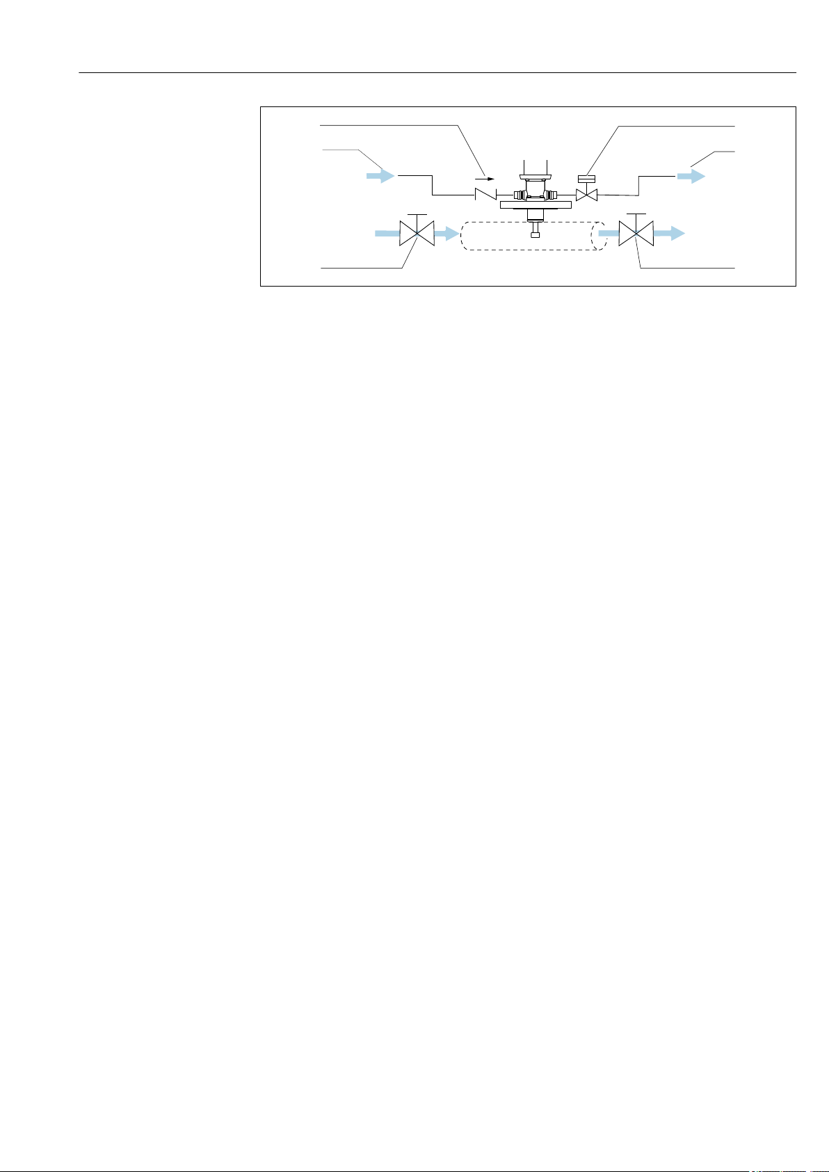
5.2 Mounting the assembly
5.2.1 Installation
Measuring system
12 Measuring system (example)
1 Cleanfit assembly CPA871
2 Measuring cable
3 Liquiline CM44x transmitter
4 Sensor
A0029620
Installation recommendation
The two O-rings of the process seal close off the process in the relevant limit position. The
assembly is open to the process during insertion/retraction; the rinse connections must
either be pipe-fitted or sealed.
The connection between the service chamber and the process is open during
movement; the sealing water function can be used as a result. The rinse chamber
outlet must be blocked (e.g., with a shutoff valve) to implement the sealing water
18 Endress+Hauser
function.
Cleanfit CPA871 Installation
1
2
3
4
5
A0039105
13 Sealing system using a bypass
1 Check valve
2 Valve open/closed, sealing water function
3 Wastewater
4 Shutoff valve open/closed
5 Water/cleaning agent
The seals must be checked and serviced regularly. Therefore measures must be taken to
separate the assembly from the process, e.g., by installing a bypass.
Endress+Hauser 19
Installation Cleanfit CPA871
Installing/removing the assembly from the process
WARNING
L
Risk of injury from high pressure, high temperature or chemical hazards if process
medium escapes.
Wear protective gloves, protective goggles and protective clothing.
‣
Mount the assembly only if vessels or pipes are empty and unpressurized.
‣
Prior to installation, check the flange seal between the flanges.
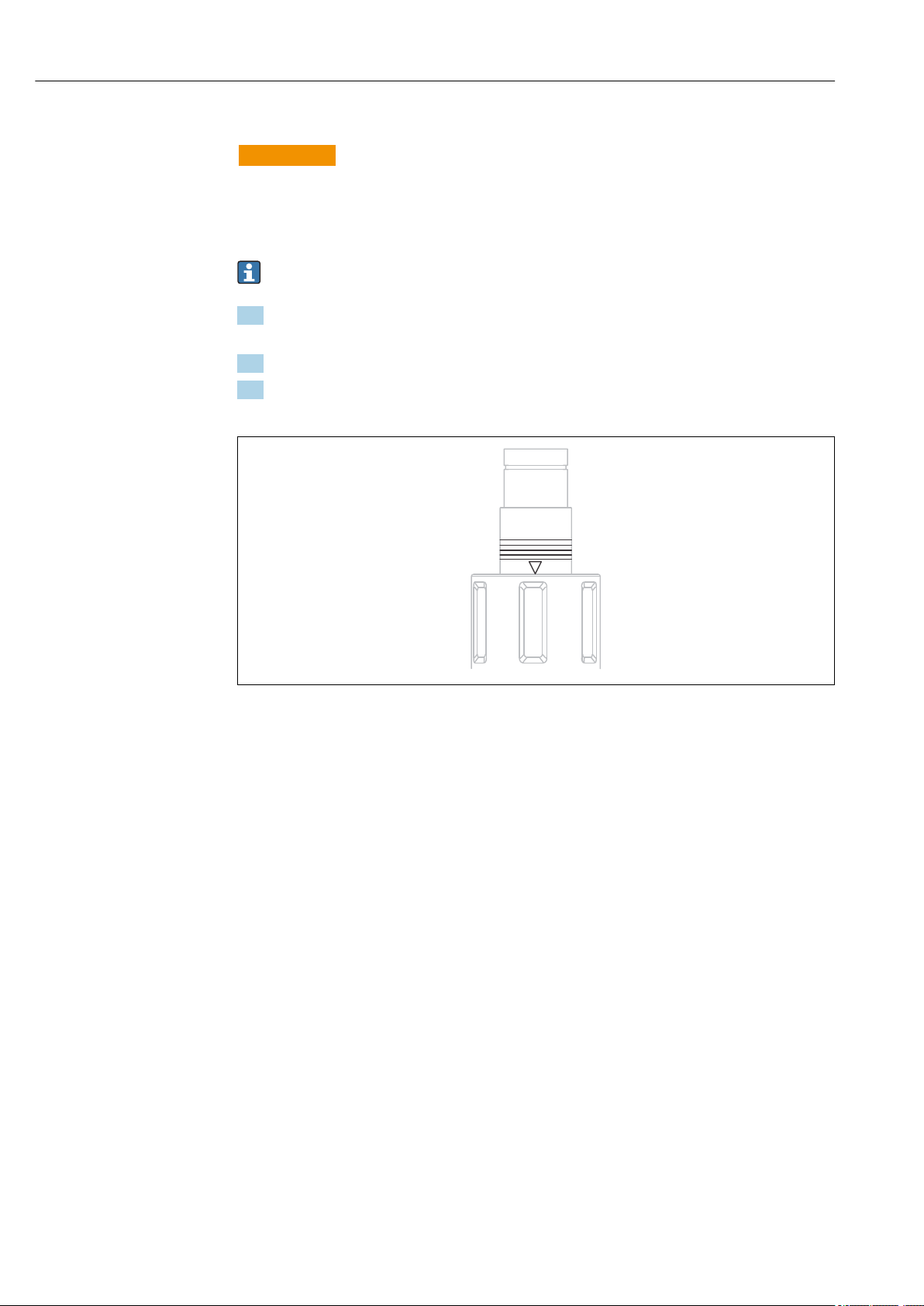
1. Move the assembly to the service position.
(The triangle position marking is visible (→ 14).
2. Secure the assembly on the tank or piping via the process connection.
3. Follow the instructions in the next section to connect pipes for compressed air and
rinse water (for the relevant assembly version).
14 Position markings (service position)
A0023307
20 Endress+Hauser
Cleanfit CPA871 Installation
1
2
3
4
5
6
7
8
Pneumatic connection for automatic operation
Prerequisites:
• Air pressure 4 to 7 bar (absolute pressure) (58 to 102 psi)
• Compressed air quality in accordance with ISO 8573-1:2001
Quality class 3.3.3 or 3.4.3
• Solids class 3 (max. 5 μm, max. 5 mg/m3, contamination with particles)
• Water content for temperatures ≥ 15 °C: Class 4 pressure condensation point 3 °C or
lower
• Water content for temperatures of 5 to 15 °C: Class 3 pressure condensation point -20 °C
or lower
• Oil content: Class 3 (max. 1 mg/m3)
• Air temperature: 5 °C or higher
• No continuous air consumption
• Minimum nominal diameter of air pipes: 2 mm (0.08 ")
A dual-operating cylinder is used to operate the pneumatic drive.
An automatic limit position lock both in service and measuring position secures the
assembly to prevent it from moving inadvertently in the event of a failure in the control
air. The assembly remains in the relevant position.
Connection: Push connector M5, hose 4/2 mm OD/ID (adapter for 6/4 mm OD/ID
enclosed)
NOTICE
Air pressure too high
Damage to seals.
Connect a pressure-reducing valve upstream if the air pressure is likely to rise to above
‣
7 bar (absolute pressure) (102 psi) (even short pressure surges).
1 Rinse connection
2 Automatic limit position lock,
process
3 Connection for limit position
switch, optional
4 Automatic limit position lock,
service
5 Fastening ring for protective
cover
6 Pneumatic connection (move
to measuring position)
7 Pneumatic connection (move
to service position)
8 Rinse connection
15 Assembly with pneumatic drive (without protective cover)
A0029614
Use a pneumatic pilot valve to insert/retract the assembly (4/2-way or 5/2-way
valve). Connect both inputs.
Endress+Hauser 21
 Loading...