

Endress+Hauser CPA450 Operating Manual
BA00183C/07/EN/15.20
71481806
2020-05-31
Products Solutions Services
Operating Instructions
Cleanfit CPA450
Retractable assembly for 12mm sensors for pH/ORP and
oxygen measurement


Cleanfit CPA450 Table of contents
Table of contents
1 About this document ................ 4
1.1 Warnings ............................ 4
1.2 Symbols used .......................... 4
1.3 Symbols on the device ................... 4
2 Basic safety instructions ............ 5
2.1 Requirements for personnel ............... 5
2.2 Designated use ........................ 5
2.3 Occupational safety ..................... 5
2.4 Operational safety ...................... 6
2.5 Product safety ......................... 6
3 Incoming acceptance and product
identification ....................... 7
3.1 Incoming acceptance .................... 7
3.2 Product identification .................... 8
3.3 Scope of delivery ....................... 8
3.4 Certificates and approvals ................ 9
4 Installation ....................... 10
4.1 Installation conditions .................. 10
4.2 Installation .......................... 13
4.3 Post-installation check .................. 18
9.3 Mechanical construction ................ 37
Index .................................. 38
5 Operation options ................. 19
5.1 Initial commissioning ................... 19
5.2 Operating elements .................... 19
5.3 Operating the assembly ................. 20
6 Maintenance ...................... 22
6.1 Cleaning the assembly .................. 22
6.2 Cleaning agent ....................... 23
6.3 Replacing seals ....................... 24
7 Repair ............................ 27
7.1 Spare parts .......................... 28
7.2 Return .............................. 31
7.3 Disposal ............................ 31
8 Accessories ....................... 32
8.1 Accessory kits ........................ 32
8.2 Welding socket ....................... 32
8.3 Safety kit ............................ 32
8.4 Sensors ............................. 33
8.5 Connection accessories .................. 34
9 Technical data .................... 36
9.1 Environment ......................... 36
9.2 Process ............................. 36
Endress+Hauser 3
About this document Cleanfit CPA450
1 About this document
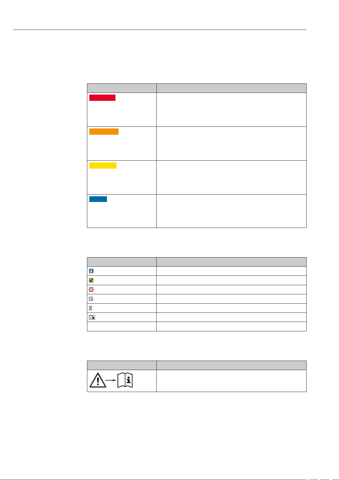
1.1 Warnings
Structure of information Meaning
DANGER
L
Causes (/consequences)
If necessary, Consequences of
non-compliance (if applicable)
Corrective action
‣
WARNING
L
Causes (/consequences)
If necessary, Consequences of
non-compliance (if applicable)
Corrective action
‣
CAUTION
L
Causes (/consequences)
If necessary, Consequences of
non-compliance (if applicable)
Corrective action
‣
NOTICE
Cause/situation
If necessary, Consequences of
non-compliance (if applicable)
Action/note
‣
This symbol alerts you to a dangerous situation.
Failure to avoid the dangerous situation will result in a fatal or serious
injury.
This symbol alerts you to a dangerous situation.
Failure to avoid the dangerous situation can result in a fatal or serious
injury.
This symbol alerts you to a dangerous situation.
Failure to avoid this situation can result in minor or more serious injuries.
This symbol alerts you to situations which may result in damage to
property.
1.2 Symbols used
Symbol Meaning
Additional information, tips
Permitted or recommended
Not permitted or not recommended
Reference to device documentation
Reference to page
Reference to graphic
Result of a step
1.3 Symbols on the device
Symbol Meaning
Reference to device documentation
4 Endress+Hauser

Cleanfit CPA450 Basic safety instructions
2 Basic safety instructions
2.1 Requirements for personnel
• Installation, commissioning, operation and maintenance of the measuring system may
be carried out only by specially trained technical personnel.
• The technical personnel must be authorized by the plant operator to carry out the
specified activities.
• The electrical connection may be performed only by an electrical technician.
• The technical personnel must have read and understood these Operating Instructions
and must follow the instructions contained therein.
• Faults at the measuring point may only be rectified by authorized and specially trained
personnel.
Repairs not described in the Operating Instructions provided must be carried out only
directly at the manufacturer's site or by the service organization.
2.2 Designated use
The assembly is designed exclusively for use in liquid media.
The manually operated Cleanfit CPA450 retractable assembly is designed for the
installation of pH, ORP and oxygen sensors in vessels and pipelines.
Thanks to its design, it can be used in pressurized systems → 36.
Use of the device for any purpose other than that described, poses a threat to the safety of
people and of the entire measuring system and is therefore not permitted.
The manufacturer is not liable for damage caused by improper or non-designated use.
2.3 Occupational safety
As the user, you are responsible for complying with the following safety conditions:
• Installation guidelines
• Local standards and regulations
Endress+Hauser 5

Basic safety instructions Cleanfit CPA450
2.4 Operational safety
Before commissioning the entire measuring point:
1. Verify that all connections are correct.
2. Ensure that electrical cables and hose connections are undamaged.
3. Do not operate damaged products, and protect them against unintentional operation.
4. Label damaged products as defective.
During operation:
If faults cannot be rectified:
‣
products must be taken out of service and protected against unintentional operation.
2.5 Product safety
2.5.1 State-of-the-art technology
The product is designed to meet state-of-the-art safety requirements, has been tested, and
left the factory in a condition in which it is safe to operate. The relevant regulations and
international standards have been observed.
6 Endress+Hauser

Cleanfit CPA450 Incoming acceptance and product identification
3 Incoming acceptance and product
identification
3.1 Incoming acceptance
1. Verify that the packaging is undamaged.
Notify the supplier of any damage to the packaging.
Keep the damaged packaging until the issue has been resolved.
2. Verify that the contents are undamaged.
Notify the supplier of any damage to the delivery contents.
Keep the damaged goods until the issue has been resolved.
3. Check that the delivery is complete and nothing is missing.
Compare the shipping documents with your order.
4. Pack the product for storage and transportation in such a way that it is protected
against impact and moisture.
The original packaging offers the best protection.
Make sure to comply with the permitted ambient conditions.
If you have any questions, please contact your supplier or your local Sales Center.
Endress+Hauser 7

Incoming acceptance and product identification Cleanfit CPA450
3.2 Product identification
3.2.1 Nameplate
The nameplate provides you with the following information on your device:
• Order code
• Serial number
• Permitted pressure
• Permitted temperature
Compare the information on the nameplate with the order.
‣
3.2.2 Product identification
Product page
www.endress.com/cpa450
Interpreting the order code
The order code and serial number of your product can be found in the following locations:
• On the nameplate
• In the delivery papers
Obtaining information on the product
1. Go to www.endress.com.
2. Call up the site search (magnifying glass).
3. Enter a valid serial number.
4. Search.
The product structure is displayed in a popup window.
5. Click on the product image in the popup window.
A new window (Device Viewer) opens. All of the information relating to your
device is displayed in this window as well as the product documentation.
3.2.3 Manufacturer's address
Endress+Hauser Conducta GmbH+Co. KG
Dieselstraße 24
D-70839 Gerlingen
3.3 Scope of delivery
The scope of delivery comprises:
• Assembly in the version ordered
• PAL mounting kit
• Hook wrench
• Operating Instructions
8 Endress+Hauser

Cleanfit CPA450 Incoming acceptance and product identification
3.4 Certificates and approvals
3.4.1 CE/PED
The assembly has been manufactured according to good engineering practice as per Article
4, Paragraph 3 of the Pressure Equipment Directive 2014/68/EU and is therefore not
required to bear the CE label.
3.4.2 EAC
The product has been certified according to guidelines TP TC 004/2011 and TP TC
020/2011 which apply in the European Economic Area (EEA). The EAC conformity mark
is affixed to the product.
Endress+Hauser 9
Installation Cleanfit CPA450
Ø 27 (1.06)
135 (5.31)
46
(1.81)
M23 + 1.5
Ø 21.2 (0.83)
Ø 25 (0.98)
Z
X
Y
Z
X
Y
X
Y
89
(3.5)
89
X
X
X
(3.5)
Y
Z
Y
Z
Y
Z
A B
C
D E
F, G
4 Installation
4.1 Installation conditions
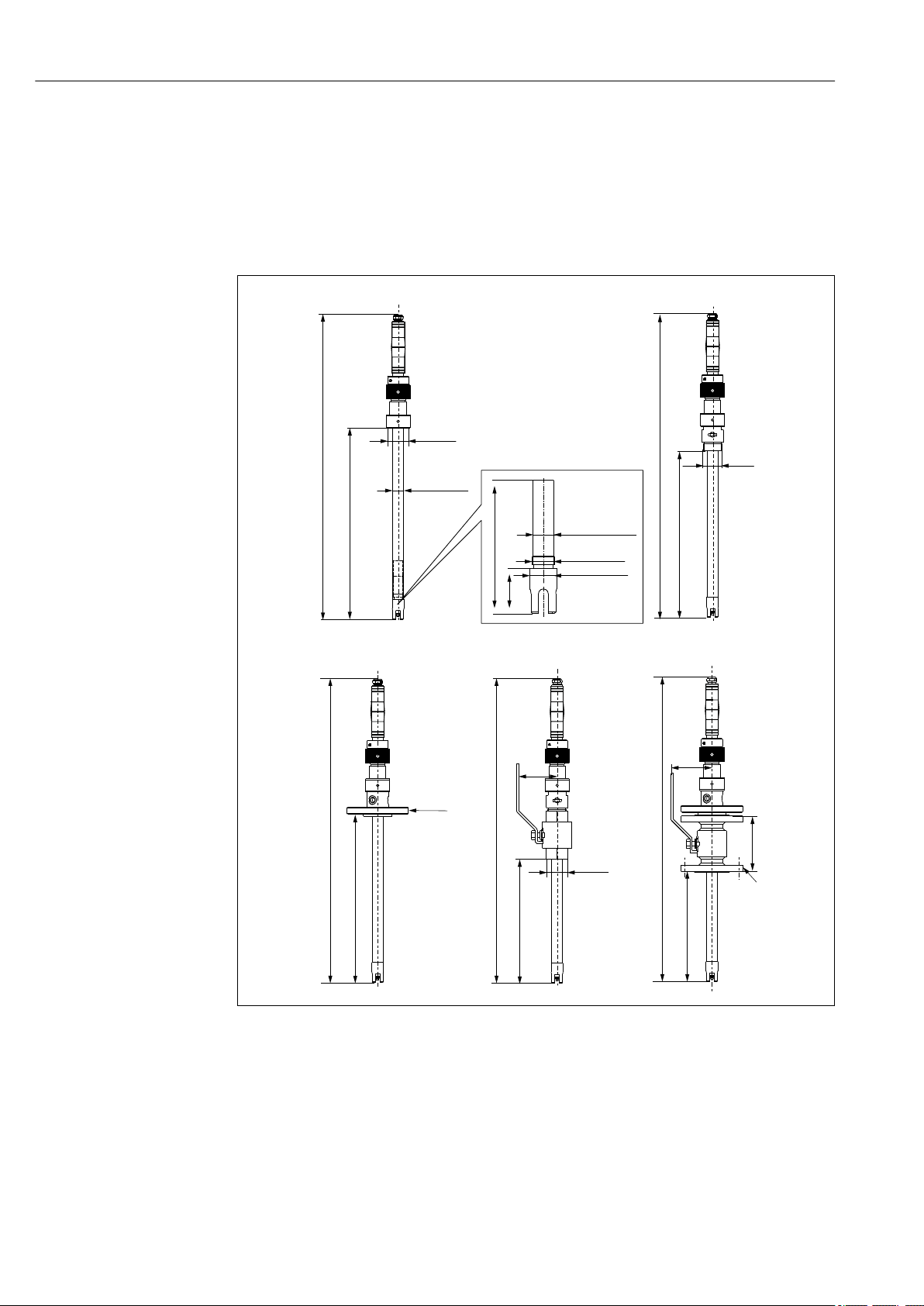
4.1.1 Dimensions and process connections
1 Dimensions (see the following table). Engineering unit in mm (inch)
F 130 mm (5.12 in) (flange DN32)
G 140 mm (5.51 in) (flange ANSI 1¼")
10 Endress+Hauser
A0037726

Cleanfit CPA450 Installation
Type Assembly Immersion depth
mm (inch)
A CPA450-*A*** 100 (3.94)
250 (9.84)
700 (27.5)
B CPA450-*B*** 100 (3.94)
250 (9.84)
700 (27.5)
B CPA450-*C*** 100 (3.94)
250 (9.84)
700 (27.5)
C CPA450-*D*** 100 (3.94)
250 (9.84)
700 (27.5)
C CPA450-*E*** 100 (3.94)
250 (9.84)
700 (27.5)
D CPA450-*F*** 100 (3.94)
250 (9.84)
700 (27.5)
D CPA450-*H*** 100 (3.94)
250 (9.84)
700 (27.5)
E CPA450-*I*** 100 (3.94)
250 (9.84)
700 (27.5)
E CPA450-*K*** 100 (3.94)
250 (9.84)
700 (27.5)
B CPA450-*M***
and
CPA450-*Q***
C CPA450-*N***
and
CPA450-*R***
100 (3.94)
250 (9.84)
700 (27.5)
100 (3.94)
250 (9.84)
700 (27.5)
X
Adapter
G1½ internal 558 (21.97)
G1¼ external 558 (21.97)
NPT 1¼" external 558 (21.97)
Flange DN32(as per DIN EN
1092-1)
Flange ANSI 1¼" (as per ASME
B16.5)
G1¼ internal 558 (21.97)
NPT 1¼" external 558 (21.97)
Flange DN32 (as per DIN EN
1092-1)
Flange ANSI 1¼" (as per ASME
B16.5)
M-NPT 1½ external 558 (21.97)
Flange ANSI 2" (as per ASME B16.5) 558 (21.97)
Y
mm (inch)Zmm (inch)
708 (27.87)
1158 (45.59)
708 (27.87)
1158 (45.59)
708 (27.87)
1158 (45.59)
558 (21.97)
708 (27.87)
1158 (45.59)
558 (21.97)
708 (27.87)
1158 (45.59)
708 (27.87)
1158 (45.59)
708 (27.87)
1158 (45.59)
558 (21.97)
708 (27.87)
1158 (45.59)
558 (21.97)
708 (27.87)
1158 (45.59)
708 (27.87)
1158 (45.59)
708 (27.87)
1158 (45.59)
275 (10.83)
425 (16.7)
875 (34.5)
220 (9.06)
370 (14.9)
820 (32.6)
220 (9.06)
370 (14.9)
820 (32.6)
225 (8.86)
375 (14.76)
825 (32.48)
225 (8.86)
375 (14.76)
825 (32.48)
130 (5.12)
280 (11.2)
730 (28.7)
130 (5.12)
280 (11.2)
730 (28.7)
92 (3.62)
242 (9.53)
792 (31.18)
82 (3.23)
232 (9.13)
782 (30.79)
220 (8.66)
370 (14.57)
820 (32.28)
225 (8.86)
375 (14.76)
825 (32.48)
4.1.2 Mounting instructions
Suitable sensors
The following sensors are suitable for installation in the assembly:
• Digital sensors with Memosens technology, length 120 mm (4.72")
• pH/ORP glass electrodes, length 120 mm (4.72")
• ISFET sensors: Only the ISFET sensors specified in the "Accessories" section can be
installed.
• Oxygen sensors, length 120 mm (4.72")
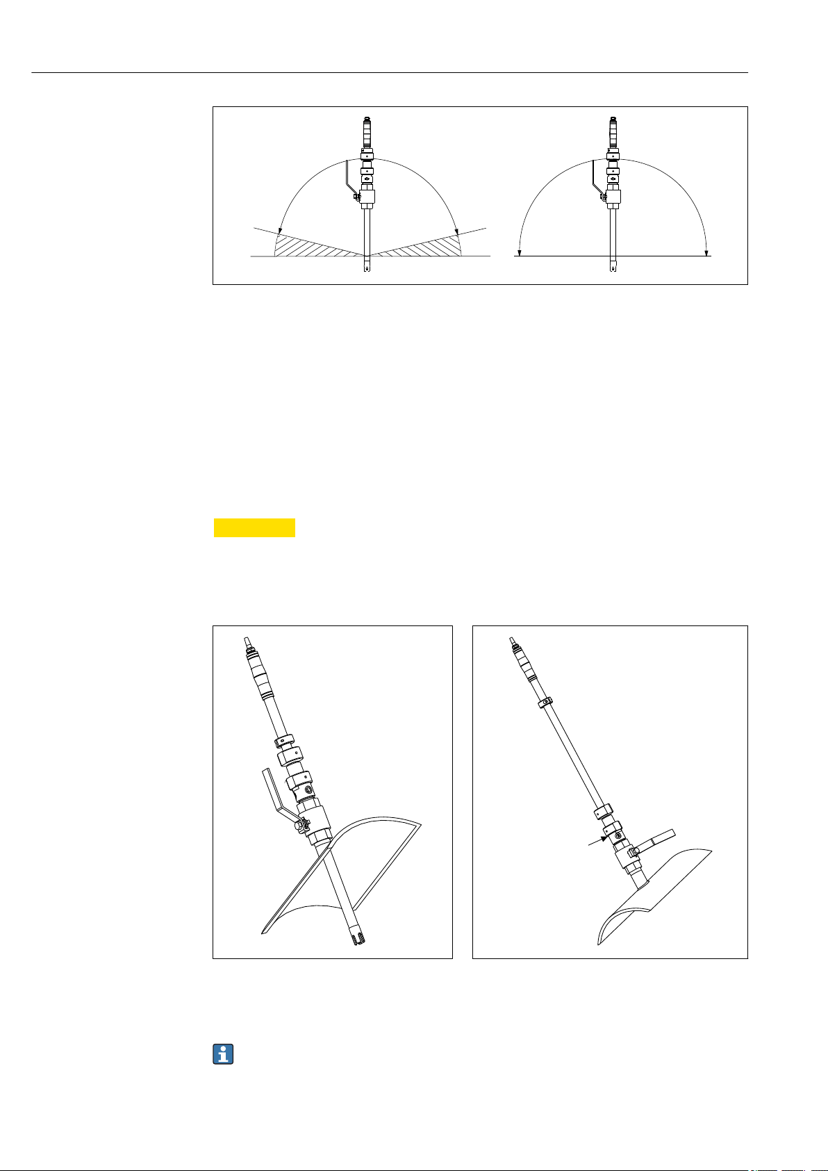
Orientation
The permitted orientation of the assembly depends on the sensor used:
• Digital sensors with Memosens technology, pH/ORP glass electrodes:
Install the assembly at an angle of at least 15° to the horizontal → 2, 12.
• ISFET sensors:
For ISFET sensors, there are basically no restrictions regarding orientation. The
installation angle should be from 0 to 180°.
• All other sensors:
Pay attention to the information in the relevant TI.
Endress+Hauser 11
Installation Cleanfit CPA450
15°
15°
A B
A
A0011679
2 Orientations
A Glass sensors: 15 ° to the horizontal
B ISFET sensors: 0 to 180° recommended
Insert the immersion assembly into the vessel or pipe to a depth that will ensure that
medium continuously washes around the electrode, even at the minimum level.
Installing with a ball valve
To replace the sensor without interrupting the process, a ball valve is required. Depending
on the version, the ball valve forms part of the assembly or must be installed by the
customer.
CAUTION
L
There is a risk of injury if used without a ball valve. due to the risk of medium
escaping.
If used without a ball valve, the process must be stopped prior to dismantling the
‣
immersion tube or replacing the sensor.
A0010209
3 Measuring mode (ball valve is open):
assembly is retracted
4 Service position (ball valve is closed): assembly is
extended for electrode replacement, calibration,
rinsing
A Top edge of adapter
Depending on the assembly version, a mounting clearance of at least 700 or 1150
mm (27.6" or 45.3") is required from the top edge of the adapter.
12 Endress+Hauser
A0010210
 Loading...