

Endress+Hauser CPA250 Operating Manual
Operating Instructions
Flowfit W CPA250
Flow assembly for pH/ORP sensors
BA041C/07/en/04.09
71093238
Brief overview
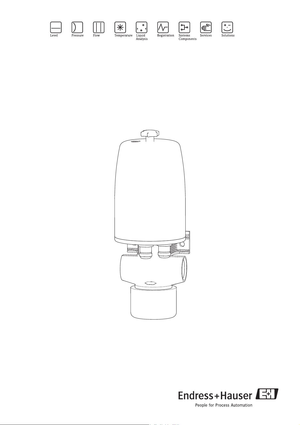
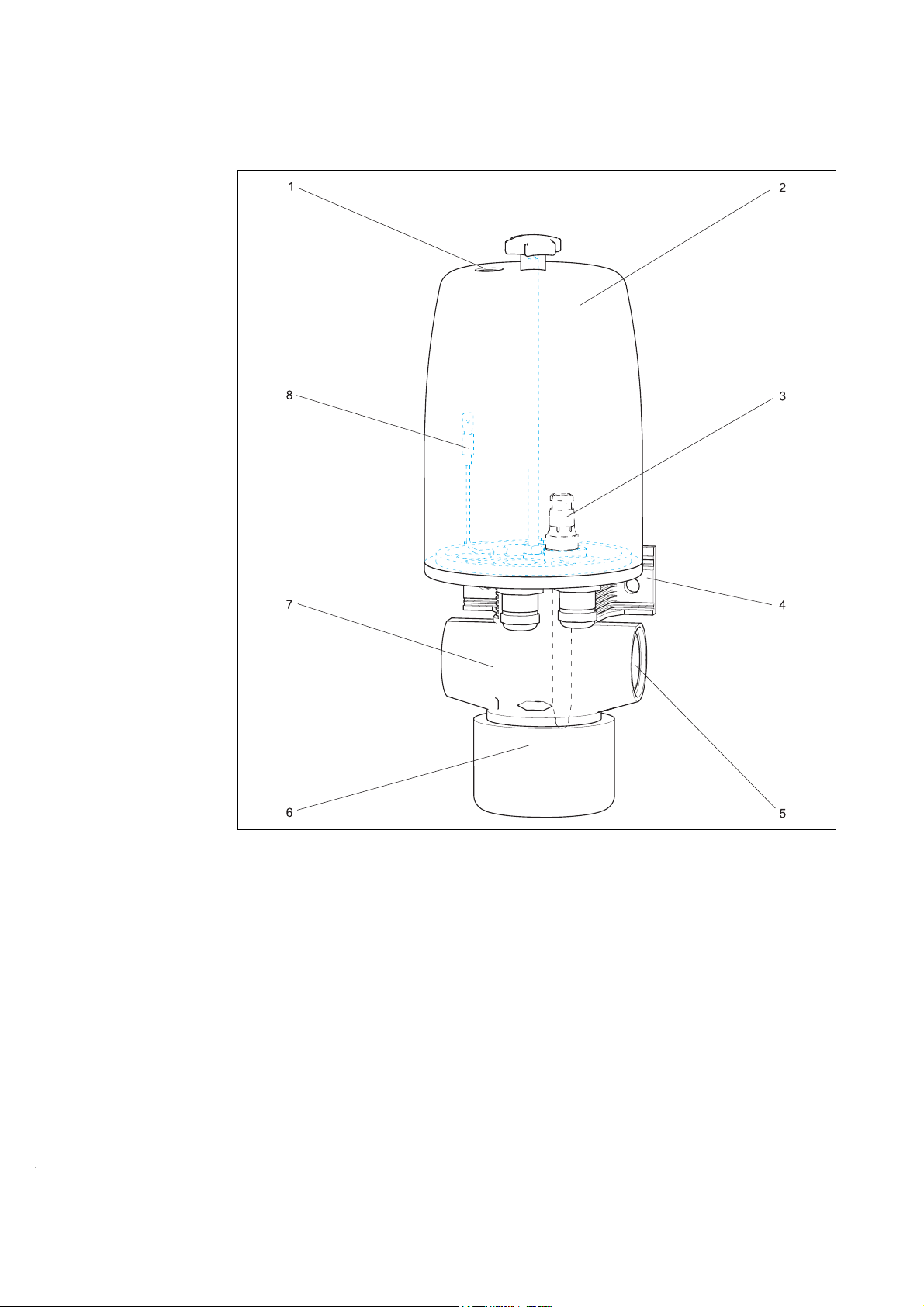
Fig. 1: CPA250 with Sensor
1)
1 Reference bore
2 Protection cover
3 pH/ORP sensor (--> accessories, not in scope of delivery)
for electrolyte supply from reservoir CPY7 (--> accessories, not in scope of delivery)
2)
4 Fastening plate
5 Process connection (depending on version)
6 Calibration vessel
7 Cable gland(s)
3)
8PML connection
1) Before connecting the electrolyte supply you must break-through the reference bore (by using a screw driver).
2) There are 3 installation positions for pH/ORP sensors (combined or single electrodes).
3) 2 cable glands are in the scope of delivery and already mounted. The third cable entry is sealed by a dummy plug.
a0007325

Table of contents
1 Safety instructions . . . . . . . . . . . . . . . . 4
1.1 Designated use . . . . . . . . . . . . . . . . . . . . . . . . . . . . 4
1.2 Installation, commissioning and operation . . . . . . . . 4
1.3 Operational safety . . . . . . . . . . . . . . . . . . . . . . . . . . 4
1.4 Return . . . . . . . . . . . . . . . . . . . . . . . . . . . . . . . . . . . 4
1.5 Notes on safety icons and symbols . . . . . . . . . . . . . . 5
2 Identification . . . . . . . . . . . . . . . . . . . . 6
2.1 Nameplate . . . . . . . . . . . . . . . . . . . . . . . . . . . . . . . 6
2.2 Product structure . . . . . . . . . . . . . . . . . . . . . . . . . . 6
2.3 Scope of delivery . . . . . . . . . . . . . . . . . . . . . . . . . . . 6
3 Installation . . . . . . . . . . . . . . . . . . . . . . 7
3.1 Incoming acceptance, transport, storage . . . . . . . . . . 7
3.2 Installation conditions . . . . . . . . . . . . . . . . . . . . . . . 7
3.3 Installation instructions . . . . . . . . . . . . . . . . . . . . . . 8
3.4 Post-installation check . . . . . . . . . . . . . . . . . . . . . . 11
4 Commissioning. . . . . . . . . . . . . . . . . . 12
5 Maintenance. . . . . . . . . . . . . . . . . . . . 13
5.1 Cleaning the assembly . . . . . . . . . . . . . . . . . . . . . . 13
5.2 Cleaning the sensor . . . . . . . . . . . . . . . . . . . . . . . . 13
5.3 Cleaning agents . . . . . . . . . . . . . . . . . . . . . . . . . . . 13
6 Accessories. . . . . . . . . . . . . . . . . . . . . 15
6.1 Accessories kits . . . . . . . . . . . . . . . . . . . . . . . . . . . 15
6.2 Sensors . . . . . . . . . . . . . . . . . . . . . . . . . . . . . . . . . 15
6.3 Cleaning systems . . . . . . . . . . . . . . . . . . . . . . . . . . 15
7 Trouble-shooting . . . . . . . . . . . . . . . . 16
7.1 Replacing damaged parts . . . . . . . . . . . . . . . . . . . . 16
7.2 Return . . . . . . . . . . . . . . . . . . . . . . . . . . . . . . . . . . 16
7.3 Disposal . . . . . . . . . . . . . . . . . . . . . . . . . . . . . . . . 16
8 Technical data . . . . . . . . . . . . . . . . . . 17
8.1 Environment . . . . . . . . . . . . . . . . . . . . . . . . . . . . . 17
8.2 Process . . . . . . . . . . . . . . . . . . . . . . . . . . . . . . . . . 17
8.3 Mechanical construction . . . . . . . . . . . . . . . . . . . . 17
Index . . . . . . . . . . . . . . . . . . . . . . . . . 18
3

Safety instructions
1 Safety instructions
1.1 Designated use
The flow assembly has been designed for the installation of pH and ORP electrodes in pipes.
Its mechanical design permits its use in pressurised systems (see "Technical data").
Any other use than the one described here compromises the safety of persons and the entire
measuring system and is not permitted.
The manufacturer is not liable for damage caused by improper or non-designated use.
1.2 Installation, commissioning and operation
Please note the following items:
• Installation, commissioning, operation and maintenance of the measuring system must only be
carried out by trained technical personnel.
Trained personnel must be authorized for the specified activities by the system operator.
• Electrical connection must only be carried out by a certified electrician.
• Technical personnel must have read and understood these Operating Instructions and must
adhere to them.
• Before commissioning the entire measuring point, check all the connections. Ensure that
electrical cables and hose connections are not damaged.
• Do not operate damaged products and secure them against unintentional commissioning.
Mark the damaged product as being defective.
• Measuring point faults may only be rectified by authorized and specially trained personnel.
• If faults can not be rectified, the products must be taken out of service and secured against
unintentional commissioning.
• Repairs not described in these Operating Instructions may only be carried out at the
manufacturer’s or by the service organization.
1.3 Operational safety
The assembly has been designed and tested in accordance with the latest industry standards and left
the factory in perfect functioning order.
Relevant regulations and standards have been met.
As the user, you are responsible for complying with the following safety conditions:
• Installation instructions
• Local prevailing standards and regulations.
1.4 Return
If the assembly has to be repaired, please return it cleaned to the appropriate sales center.
Please use the original packaging, if possible.
Please enclose the completed "Declaration of contamination" (copy the second to last page of these
Operating Instructions) with the packaging and the transportation documents.
No repair without completed "Declaration of contamination"!
4

#
"
!
Safety instructions
1.5 Notes on safety icons and symbols
Warning!
This symbol alerts you to hazards that can cause serious damage to the instrument or to persons if
ignored.
Caution!
This symbol alerts you to possible faults which could arise from incorrect operation. They could
cause damage to the instrument if ignored.
Note!
This symbol indicates important items of information.
5
Identification
2 Identification
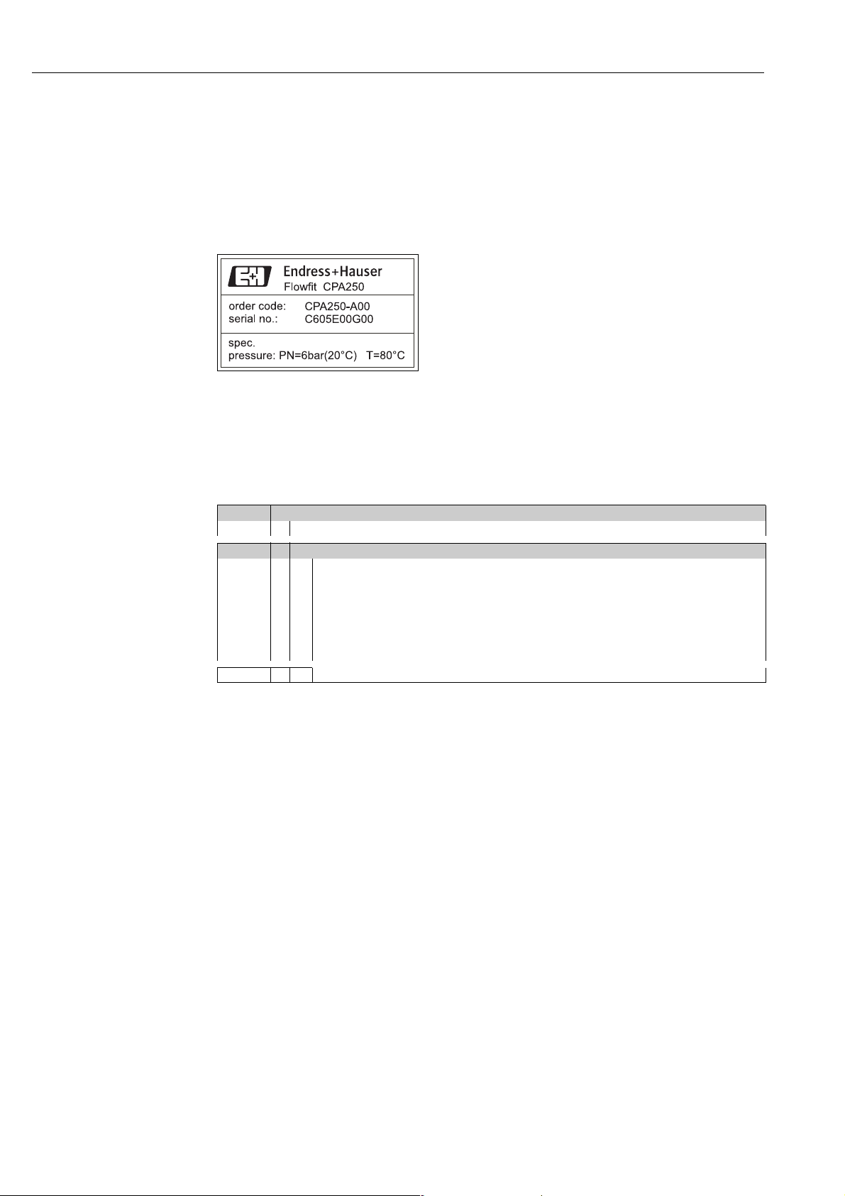
2.1 Nameplate
You can identify the assembly version by the order code on the nameplate. Please compare this code
with your order.
a0007302
Fig. 2: Example of a nameplate
You can find possible assembly versions and the resulting order codes in the product structure.
2.2 Product structure
Design
A Mounting places for 3 sensors
Process connection, Material, Potential matching pin (PMP)
00 G1, PP, PMP 1.4571 (316 Ti)
01 G1, PP, PMP titanium
02 NPT 1", PP, PMP 1.4571 (316 Ti)
03 NPT 1", PP, PMP titanium
04 NPT 1", PP, no PMP
05 G1, PP, no PMP
30 G1, PP LABS free, PMP titanium
CPA250- complete order code
2.3 Scope of delivery
The scope of delivery comprises:
• Flowfit assembly (ordered version)
• Operating Instructions (English)
If you have any questions, please contact your supplier or your local sales center.
6
 Loading...