

Page 1
BA01845C/07/EN/01.18
71406304
2018-04-30
Products Solutions Services
Operating Instructions
Liquiline Compact CM82
Compact transmitter configurable for Memosens sensors
from the Liquiline series
Page 2

Page 3

Liquiline Compact CM82 Table of contents
Table of contents
1 Document information .............. 4
1.1 Warnings ............................ 4
1.2 Symbols .............................. 4
1.3 Symbols at the device .................... 4
1.4 Documentation ........................ 5
2 Basic safety instructions ............ 6
2.1 Requirements for personnel ............... 6
2.2 Designated use ........................ 6
2.3 Occupational safety ..................... 6
2.4 Operational safety ...................... 6
3 Product description ................. 8
3.1 Product design ......................... 8
4 Incoming acceptance and product
identification ....................... 9
4.1 Incoming acceptance .................... 9
4.2 Product identification .................... 9
4.3 Scope of delivery ...................... 10
4.4 Certificates and approvals ............... 10
5 Installation ....................... 12
5.1 Dimensions .......................... 12
6 Electrical connection .............. 13
6.1 Connection .......................... 13
6.2 Post-connection check .................. 14
7 Operation options ................. 15
7.1 Overview of operating options ............ 15
7.2 Access to operating menu via SmartBlue
(app) ............................... 15
7.3 Access to operating menu via RIA15 ........ 17
10 Operation ......................... 35
10.1 Reading measured values ................ 35
10.2 Adapting the measuring device to the process
conditions ........................... 36
11 Diagnostics and troubleshooting ... 38
11.1 Diagnostic information via LED ........... 38
11.2 Adapting the diagnostic information ....... 38
11.3 Adapting sensor diagnostic information ..... 39
11.4 Simulation ........................... 47
11.5 Diagnostic list ........................ 48
11.6 Event logbook ........................ 62
11.7 Resetting the measuring device ........... 62
11.8 Device information .................... 63
11.9 Firmware history ..................... 63
12 Maintenance ...................... 64
12.1 Maintenance tasks ..................... 64
13 Repair ............................ 65
13.1 General notes ........................ 65
13.2 Return .............................. 65
13.3 Disposal ............................ 65
14 Accessories ....................... 66
14.1 Sensors ............................. 66
14.2 Software ............................ 69
14.3 Other accessories ...................... 69
15 Technical data .................... 71
15.1 Input ............................... 71
15.2 Output ............................. 71
15.3 Power supply ......................... 71
15.4 Performance characteristics .............. 72
15.5 Environment ......................... 72
15.6 Mechanical construction ................ 73
8 System integration ................ 18
8.1 Integrating the measuring device into the
system ............................. 18
Index .................................. 75
9 Commissioning .................... 19
9.1 Preparatory steps ...................... 19
9.2 Function check ....................... 19
9.3 Establishing connection via SmartBlue (app) .. 20
9.4 Establishing a connection via RIA15 ........ 21
9.5 Setting the operating language ............ 27
9.6 Date and time ........................ 27
9.7 Configuring the measuring device .......... 27
9.8 Configuration management .............. 34
9.9 Unauthorized access ................... 34
Endress+Hauser 3
Page 4
Document information Liquiline Compact CM82
1 Document information
1.1 Warnings
Structure of information Meaning
DANGER
L
Causes (/consequences)
If necessary, Consequences of
non-compliance (if applicable)
Corrective action
‣
WARNING
L
Causes (/consequences)
If necessary, Consequences of
non-compliance (if applicable)
Corrective action
‣
CAUTION
L
Causes (/consequences)
If necessary, Consequences of
non-compliance (if applicable)
Corrective action
‣
NOTICE
Cause/situation
If necessary, Consequences of
non-compliance (if applicable)
Action/note
‣
This symbol alerts you to a dangerous situation.
Failure to avoid the dangerous situation will result in a fatal or serious
injury.
This symbol alerts you to a dangerous situation.
Failure to avoid the dangerous situation can result in a fatal or serious
injury.
This symbol alerts you to a dangerous situation.
Failure to avoid this situation can result in minor or more serious injuries.
This symbol alerts you to situations which may result in damage to
property.
1.2 Symbols
Symbol Meaning
Additional information, tips
Permitted or recommended
Not permitted or not recommended
Reference to device documentation
Reference to page
Reference to graphic
Result of a step
1.3 Symbols at the device
Symbol Meaning
Reference to device documentation
4 Endress+Hauser
Page 5

Liquiline Compact CM82 Document information
1.4 Documentation
The following instructions complement these Operating Instructions and are available on
the product pages on the Internet:
Operating Instructions Memosens, BA01245C
– Software description for Memosens inputs
– Calibration of Memosens sensors
– Sensor-specific diagnostics and troubleshooting
Endress+Hauser 5
Page 6

Basic safety instructions Liquiline Compact CM82
2 Basic safety instructions
2.1 Requirements for personnel
• Installation, commissioning, operation and maintenance of the measuring system may
be carried out only by specially trained technical personnel.
• The technical personnel must be authorized by the plant operator to carry out the
specified activities.
• The electrical connection may be performed only by an electrical technician.
• The technical personnel must have read and understood these Operating Instructions
and must follow the instructions contained therein.
• Faults at the measuring point may only be rectified by authorized and specially trained
personnel.
Repairs not described in the Operating Instructions provided must be carried out only
directly at the manufacturer's site or by the service organization.
2.2 Designated use
The Liquiline CM72 Liquiline CM82 is a transmitter for connecting digital sensors with
Memosens technology, configurable, with 4..20 mA/HART communication and optional
operation via smartphone or other mobile devices via Bluetooth.
The device is designed for use in the following industries:
• Life science
• Chemical industry
• Water and wastewater
• Food and beverages
• Power stations
• Other industrial applications
2.3 Occupational safety
As the user, you are responsible for complying with the following safety conditions:
• Installation guidelines
• Local standards and regulations
• Regulations for explosion protection
Electromagnetic compatibility
• The product has been tested for electromagnetic compatibility in accordance with the
applicable European standards for industrial applications.
• The electromagnetic compatibility indicated applies only to a product that has been
connected in accordance with these Operating Instructions.
2.4 Operational safety
Before commissioning the entire measuring point:
1. Verify that all connections are correct.
2. Ensure that electrical cables and hose connections are undamaged.
3. Do not operate damaged products, and protect them against unintentional operation.
4. Label damaged products as defective.
6 Endress+Hauser
Page 7

Liquiline Compact CM82 Basic safety instructions
During operation:
If faults cannot be rectified:
‣
products must be taken out of service and protected against unintentional operation.
CAUTION
L
Cleaning not switched off during calibration or maintenance activities
Risk of injury due to medium or cleaning agent!
If a cleaning system is connected, switch it off before removing a sensor from the
‣
medium.
If you wish to check the cleaning function and have therefore not switched off the
‣
cleaning system, wear protective clothing, goggles and gloves or take other appropriate
measures.
Endress+Hauser 7
Page 8

Product description Liquiline Compact CM82
1
2
3
4
3 Product description
3.1 Product design
A0036216
1 Transmitter design
1 Cable
2 Housing
3 Memosens connection
4 LED, for optical signaling of operating statuses of measuring point
3.1.1 Measuring parameters
The transmitter is designed for digital Memosens sensors with inductive plug-in head:
• pH, ORP. pH/ORP combined sensors
• Conductive Conductivity
• Dissolved oxygen
8 Endress+Hauser
Page 9

Liquiline Compact CM82 Incoming acceptance and product identification
4 Incoming acceptance and product
identification
4.1 Incoming acceptance
1. Verify that the packaging is undamaged.
Notify the supplier of any damage to the packaging.
Keep the damaged packaging until the issue has been resolved.
2. Verify that the contents are undamaged.
Notify the supplier of any damage to the delivery contents.
Keep the damaged goods until the issue has been resolved.
3. Check that the delivery is complete and nothing is missing.
Compare the shipping documents with your order.
4. Pack the product for storage and transportation in such a way that it is protected
against impact and moisture.
The original packaging offers the best protection.
Make sure to comply with the permitted ambient conditions.
If you have any questions, please contact your supplier or your local Sales Center.
4.2 Product identification
4.2.1 Nameplate
The nameplate provides you with the following information on your device:
• Manufacturer identification
• Order code
• Extended order code
• Serial number
• Firmware version
• Ambient and process conditions
• Input and output values
• Safety information and warnings
• Approvals as per version ordered
Compare the data on the nameplate with your order.
‣
4.2.2 Product identification
Product page
www.endress.com/CM82
Interpreting the order code
The order code and serial number of your product can be found in the following locations:
• On the nameplate
• In the delivery papers
Obtaining information on the product
1. Open the product website.
2. In the page header, select: Product tools.
Online Tools: An additional area opens up.
Endress+Hauser 9
Page 10

Incoming acceptance and product identification Liquiline Compact CM82
3. Select: Access device specific information.
An additional window opens.
4. Enter the order code from the nameplate into the search field. Then select: Show
details.
Details of each feature (selected option) of the order code are displayed.
4.3 Scope of delivery
The scope of delivery includes:
• CM82
• Brief Operating Instructions
If you have any queries:
‣
Please contact your supplier or local sales center.
4.4 Certificates and approvals
4.4.1
Endress+Hauser Conducta GmbH+CO. KG hereby declares that the radio system type
CM82 complies with directives 2014/53/EU and 2011/65/EU.
The complete text of the EU declaration of conformity can be found at the following web
address: "http://www.endress.com/CM82"
Frequency band: 2400-2483.5 MHz, power output: < 10dBm EIRP
mark
4.4.2 FCC/IC
Radio approval for USA/Canada
This device complies with Part 15 of the FCC Rules [and with Industry Canada licenseexempt RSS standard(s)]. Operation is subject to the following two conditions: (1) this
device may not cause harmful interference, and (2) this device must accept any
interference received, including interference that may cause undesired operation.
Any changes or modifications made to this equipment not expressly approved by Endress
+Hauser may void the FCC authorization to operate this equipment. This device complies
with Part 15 of the FCC Rules and with Industry Canada license- exempt RSS standard(s).
Operation is subject to the following two conditions:
• this device may not cause harmful interference, and
• this device must accept any interference received, including interference that may cause
undesired operation.
Le présent appareil est conforme aux CNR d'Industrie Canada applicables aux appareils
radio exempts de licence. L'exploitation est autorisée aux deux conditions suivantes:
• l'appareil ne doit pas produire de brouillage, et
• l'utilisateur de l'appareil doit accepter tout brouillage radioélectrique subi, même si le
brouillage est susceptible d'en compromettre le fonctionnement.
Note: This equipment has been tested and found to comply with the limits for a Class B
digital device, pursuant to part 15 of the FCC Rules. These limits are designed to provide
reasonable protection against harmful interference in a residential installation. This
equipment generates, uses and can radiate radio frequency energy and, if not installed and
used in accordance with the instructions, may cause harmful interference to radio
communications. However, there is no guarantee that interference will not occur in a
particular installation. If this equipment does cause harmful interference to radio or
television reception, which can be determined by turning the equipment off and on, the
10 Endress+Hauser
Page 11

Liquiline Compact CM82 Incoming acceptance and product identification
202-LSF040
R
R-CRM-E1H-CM82A
user is encouraged to try to correct the interference by one or more of the following
measures:
• Increase the separation between the equipment and receiver.
• Consult the dealer or an experienced radio technician for help.
Radio approval for Japan
A0036603
Japanese Radio Law and Japanese Telecommunications Business Law Compliance. This
device is granted pursuant to the Japanese Radio Law (電波法). This device should not be
modified (otherwise the granted designation number will become invalid).
Radio approval for China
Certification number: CMIIT ID: 2017DJ6495
Radio approval for South Korea
A0036602
Endress+Hauser 11
Page 12
Installation Liquiline Compact CM82
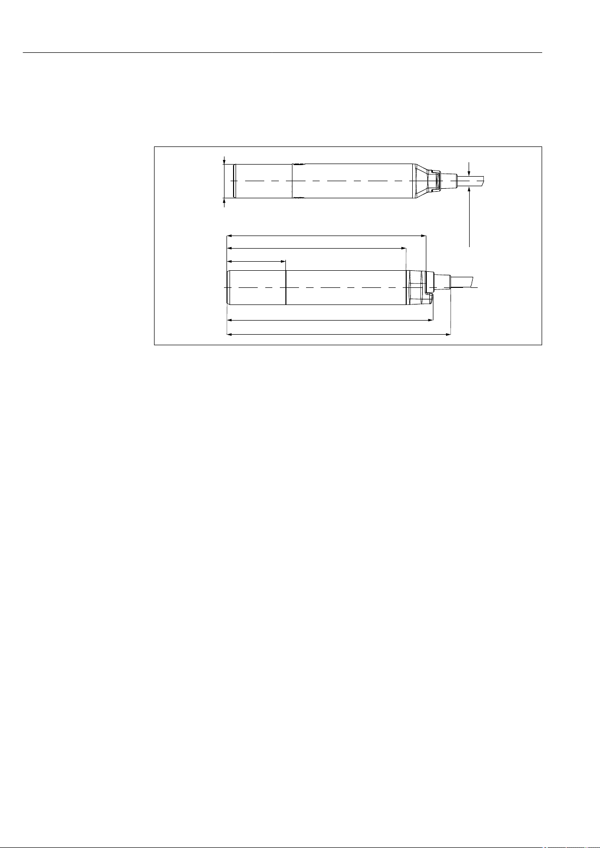
110.8 (4.33)
99.8 (3.92)
32.75 (1.29)
114.7 (4.52)
124.6 (4.90)
Ø
18.95 (0.75)
Ø
5.5 (0.22)
5 Installation
5.1 Dimensions
2 Dimensions in mm (inch)
A0033272
12 Endress+Hauser
Page 13
Liquiline Compact CM82 Electrical connection
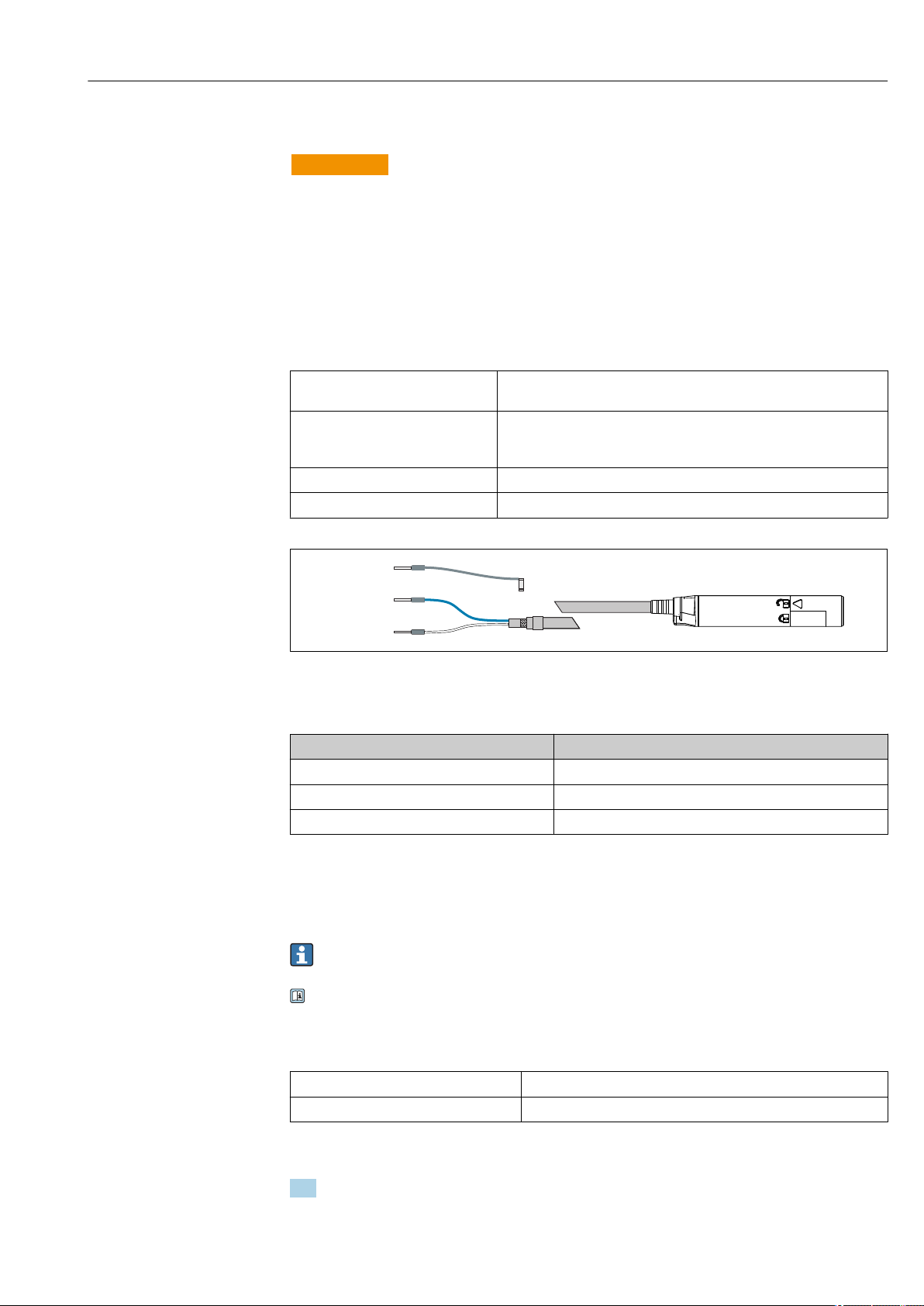
GN/YE
BU
WH
+
–
GN/YE
GND
GY
6 Electrical connection
WARNING
L
Device is live!
Incorrect connection may result in injury or death!
The electrical connection may be performed only by an electrical technician.
‣
The electrical technician must have read and understood these Operating Instructions
‣
and must follow the instructions contained therein.
Prior to commencing connection work, ensure that no voltage is present on any cable.
‣
6.1 Connection
Supply voltage: 12,6 to 30 VDC (In the case of a residual current > 20 mA)
14 to 30 VDC (When the failure current is set to 3.6 mA.)
Cable length: 3 m (10 ft)
7 m (23 ft)
15 m (46 ft)
Signal output: 4 to 20 mA
Signal on alarm: 3.6 to 23 mA
3 Electrical connection
Connect ferrules as specified in the table:
‣
Cable Function
Gray (GY) Grounding, GND
BU (blue) 4 to 20 mA +
White (WH) 4 to 20 mA -
The grounding cable must be provided by the customer.
6.1.1 With RIA15
The RIA15 process display unit is loop-powered and does not require any external
power supply.
Further information is available in the RIA15 Operating Instructions BA01170K.
6.1.2 With junction box
Max. operating voltage: 30 V
Max. operating current 30 mA
A0033282
Wiring
1. Unscrew cover and remove.
The terminal assignment is indicated in the box.
Endress+Hauser 13
Page 14

Electrical connection Liquiline Compact CM82
1
2
3
4
5
6
7
8
9
10
11
12
0/4...20 mA Source+
0/4...20 mA Source+
0/4...20 mA Source-
Display+
Display (Bridge)
Display- or LED
Sensor+ (w/Display)
Sensor+ (w/o Display)
Sensor-
Shield
HART-
HART+
2. Guide the cable cores through the M16 cable gland.
3. Connect cores in accordance with the assignment provided.
A0034718
4 Terminal diagram
Further information is available in the Operating Instructions BA01802C.
6.2 Post-connection check
WARNING
L
Connection errors
The safety of people and of the measuring point is under threat. The manufacturer does
not accept any responsibility for errors that result from failure to comply with the
instructions in this manual.
Put the device into operation only if you can answer yes to all the following questions.
‣
Electrical connection
Is the device or cable undamaged (visual inspection)?
‣
Do the mounted cables have adequate strain relief?
‣
Are the cables routed without loops and cross-overs?
‣
Does the supply voltage match the specifications on the nameplate?
‣
No reverse polarity, is terminal assignment correct?
‣
14 Endress+Hauser
Page 15
Liquiline Compact CM82 Operation options
EH_FMRx0_0123456
CM82_M50053105G11
7 Operation options
7.1 Overview of operating options
Operation and settings via:
• SmartBlue (app)
• RIA15 (with reduced operating function compared to app and HART)
• PLC control station (via HART)
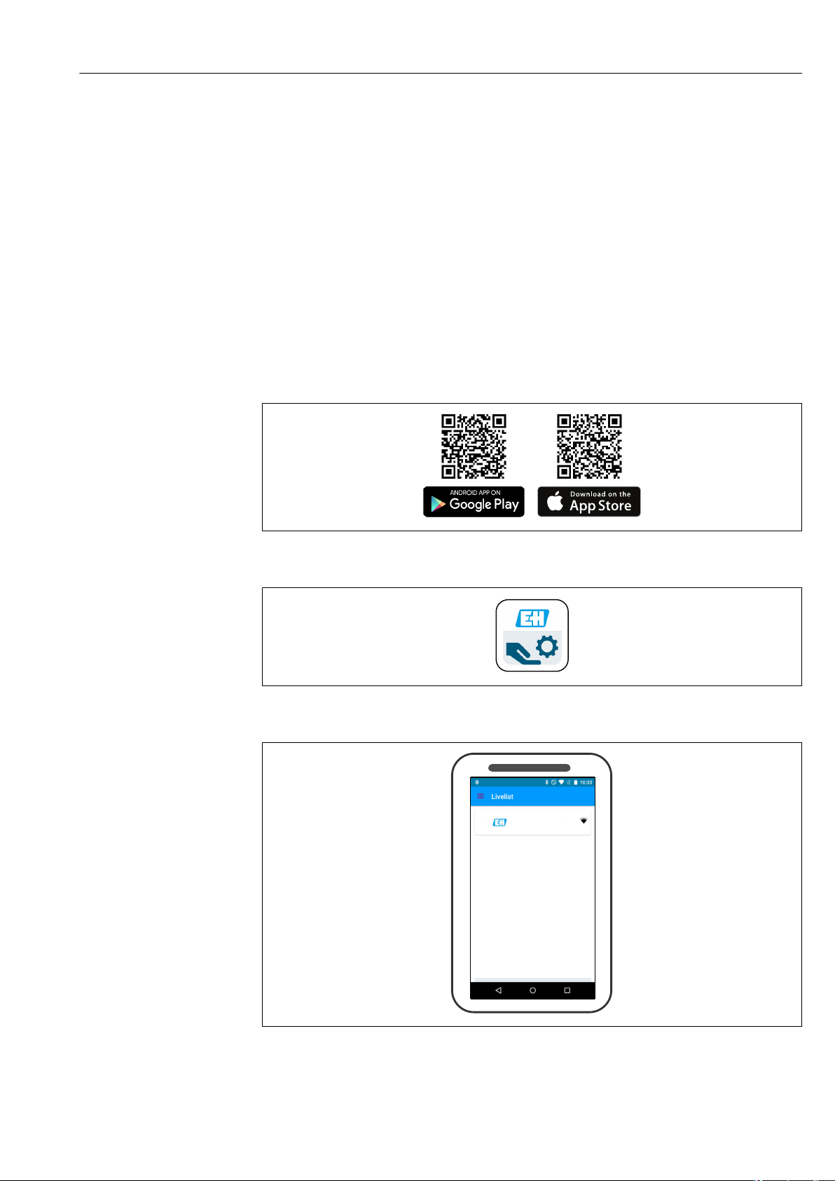
7.2 Access to operating menu via SmartBlue (app)
SmartBlue is available as a download for Android terminals from the Google Playstore and
for iOS devices from the Apple iTunes Store.
If you scan the QR code, you will be brought directly to the app:
5 Download links
6 SmartBlue App
A0031189-EN
A0029747
7 Livelist
The Livelist displays all of the devices that are within range.
Endress+Hauser 15
A0035117
Page 16
Operation options Liquiline Compact CM82
System requirements
• iOS devices: iPhone 4S or higher from iOS9.0; iPad2 or higher from iOS9.0; iPod Touch
5. Generation or higher from iOS9.0
• Devices with Android: from Android 4.4 KitKat and Bluetooth® 4.0
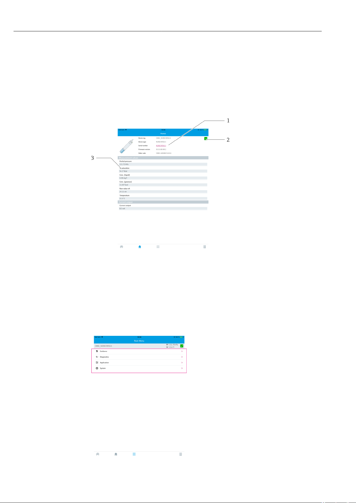
7.2.1 Structure and function of the operating menu
In the Home view, the current measured values are displayed along with the device
information (tag, serial number, firmware version, order code).
8 Overview of current measured values
1 System and device information CM82
2 Shortcut to diagnostic list
3 Overview of measured values of connected sensor
The device is operated via four main menus:
• Guidance
• Diagnostics
• Application
• System
9 Main menu
16 Endress+Hauser
Page 17
Liquiline Compact CM82 Operation options
Menu Function
Guidance Contains functions involving a self-contained sequence of activities, e.g. for calibration (="Wizard",
guided operation).
Diagnostics Contains information regarding operation, diagnostics and troubleshooting, as well as
configuration of the diagnostic behavior.
Application Sensor data for specific optimization and for detailed process adjustment. Adjustment of
measuring point to the application.
System These menus contain parameters for configuring the overall system.
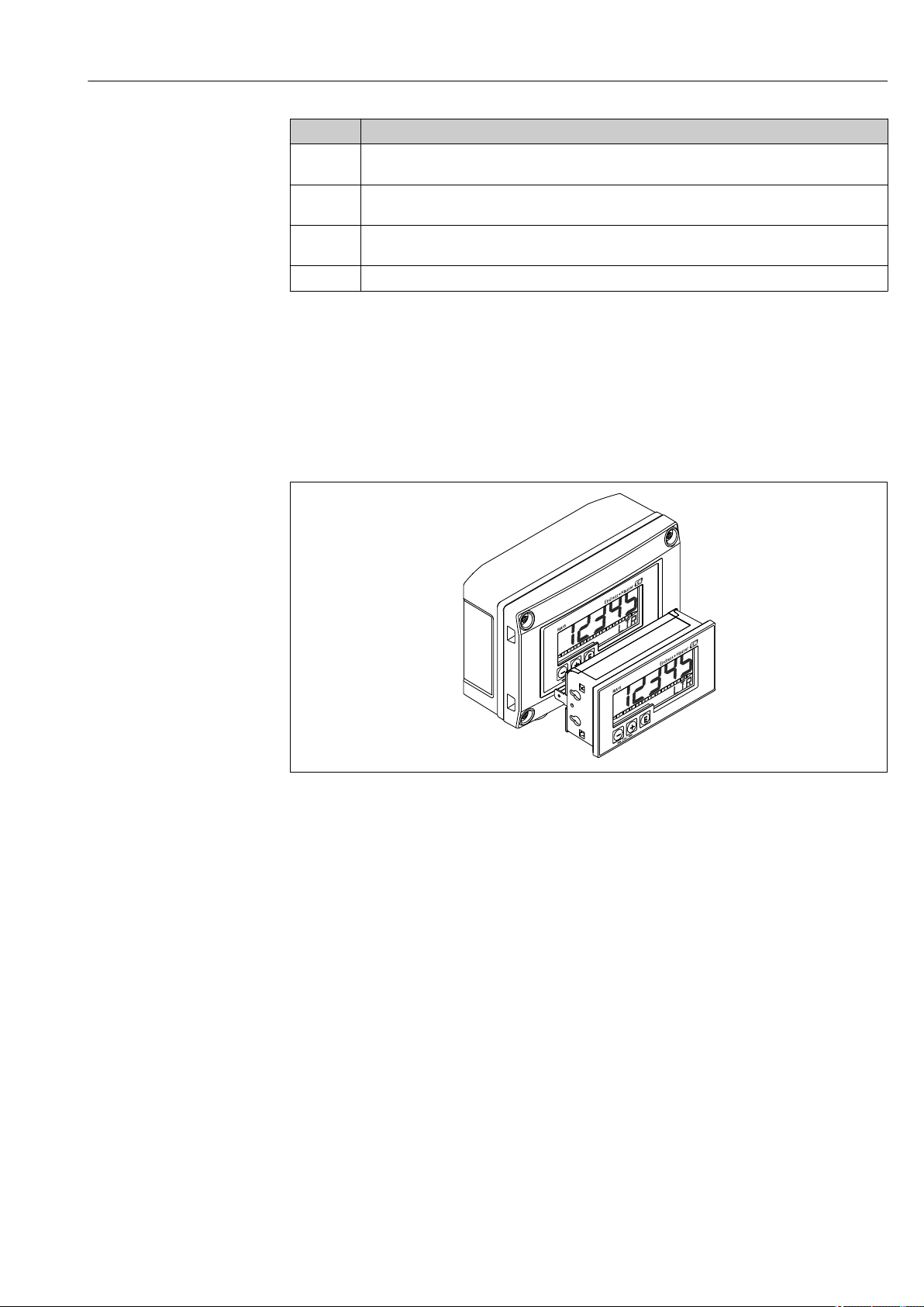
7.3 Access to operating menu via RIA15
The RIA15 process indicator is incorporated into the 4 to 20 mA/HART® loop and displays
the measuring signal in digital form. The process indicator does not require an external
power supply. It is powered directly from the current loop.
By means of HART® communication, the RIA15 enables configuration and commissioning
of selected field devices and readouts of device/sensor status messages.
10 Process display unit RIA15
A0017816
Endress+Hauser 17
Page 18
System integration Liquiline Compact CM82
1
2
8 System integration
8.1 Integrating the measuring device into the system
Interfaces for measured value transmission:
• 4 to 20 mA
• Bluetooth® LE wireless technology
• HART
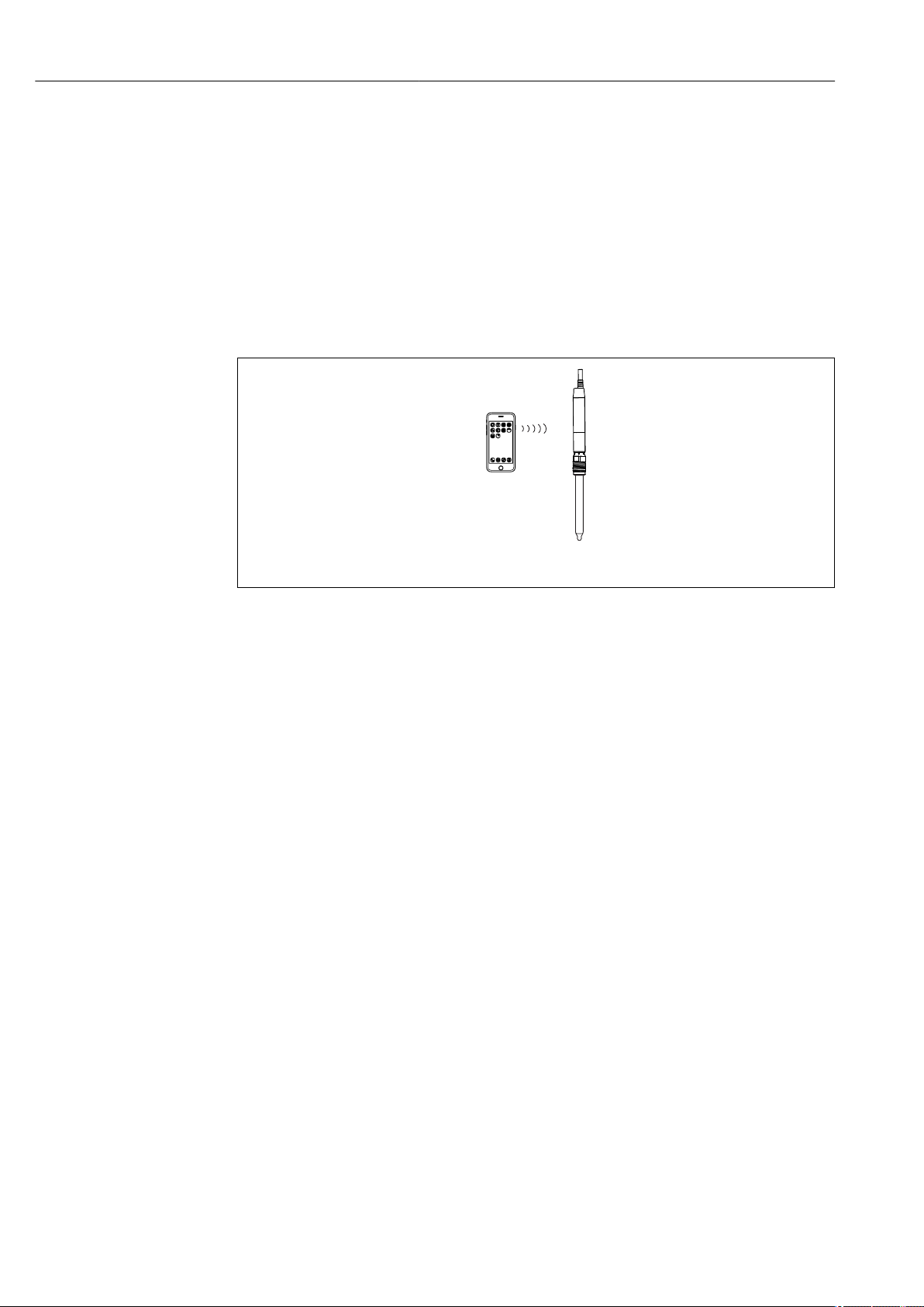
8.1.1 Bluetooth® wireless technology
11 Options for remote operation via Bluetooth® LE wireless technology
1 Smartphone / tablet with SmartBlue (app)
3 Transmitter with Bluetooth® wireless technology
8.1.2 HART
In addition to the analog 4 ... 20 mA signal, as well as the status of the device can be
transmitted digitally.
Parameterisation is also possible using an additional control unit and a suitable driver.
HART operation is possible via the following hosts (at least):
• Fieldcare und kompatible DTM-Hosts
• SFX350 Handheld
• Emerson 475 Handheld
• Emerson AMS
• Siemens PDM
A0036075
18 Endress+Hauser
Page 19
Liquiline Compact CM82 Commissioning
ESC
E
+
1
3
4
2
5
6
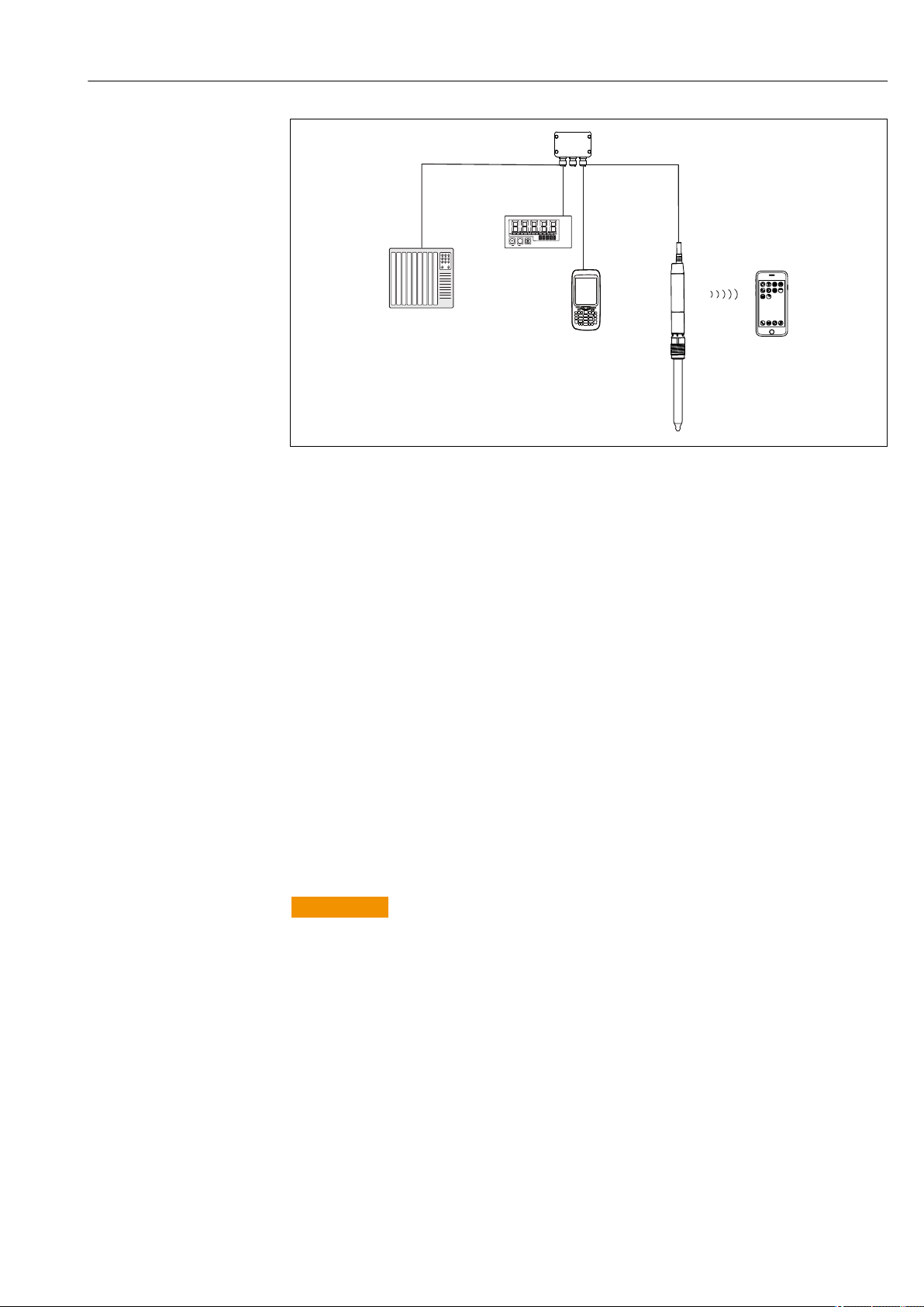
A0036740
12 Wiring options for remote operation via HART protocol
1 PLC (programmable logic controller)
2 Loop-powered process display unit RIA15, optional
3 HART control unit (e.g. SFX350)
4 Junction box
5 Transmitter with Bluetooth® LE wireless technology
6 Optional: Smartphone / tablet with SmartBlue (app)
9 Commissioning
9.1 Preparatory steps
Connect the device.
‣
The device starts up and transmits the measured value as a current value.
To operate via the SmartBlue, the Bluetooth® LE signal on the smartphone or tablet must
be switched on.
9.2 Function check
WARNING
L
Incorrect connection, incorrect supply voltage
Safety risks for staff and device malfunctions!
Check that all connections have been established correctly in accordance with the
‣
wiring diagram.
Ensure that the supply voltage matches the voltage indicated on the nameplate.
‣
Familiarize yourself with the operation of the device before it is first switched on. In
particular please read the "Basic safety instructions" sections. After power-up, the device
performs a self-test and then goes to the measuring mode.
Endress+Hauser 19
Page 20
Commissioning Liquiline Compact CM82
9.2.1 LED display
LED messages signal the status of the device and sensor.
LED behavior Status
Green
Flashes quickly
Green
Flashes twice
Green
Flashes slowly
Green
Flashes quickly three times
Red
Flashes quickly
Red, green
Three red flashes
alternating with three
green flashes
Everything OK
Device starting up
Everything OK
Read out Memosens sensor information from sensor to transmitter (sensor type,
calibration data, etc.)
Everything OK
Sensor and device OK and functioning correctly.
Everything OK
Measured value at PLC in automatic HOLD.
If the "Sensor replacement alarm delay" is exceeded, the device transmits a signal
on alarm.
The automatic hold is set to 30 seconds but can be configured to suit the
customer's needs.
Failure of device or sensor
Fault state as per NAMUR NE107
Squawk
Squawk is signaled briefly while the connection is established. Squawk can also be
activated via the app. This makes it possible to locate the device more quickly, e. g.
when several devices are installed, you can see which one the connection is
established with.
9.3 Establishing connection via SmartBlue (app)
1. Download and install the SmartBlue.
2. Start the SmartBlue.
3. Select device from livelist displayed. All available devices are displayed.
4. Perform login
5. Enter user name -> admin
6. Enter initial password -> device serial number
7. It is advisable to change the user name and password after logging in for the first
time.
You can drag additional information (e.g. main menu) onto the screen by swiping
across the screen
9.3.1 System settings
Path: Settings
Function Options Info
Information
Version Displays the app version
About Endress+Hauser Manufacturer's information
User interface
Language Picklist of
different
languages
Change language
20 Endress+Hauser
Page 21
Liquiline Compact CM82 Commissioning
ESC
E
+
1
4
2
3
A
B
Path: Settings
Function Options Info
Save device login
passwords
Device List
Sorting Selection
Show demo devices Selection
Selection
• Off
• 5 minutes
• 15 minutes
• 60 minutes
• Signal
strength
• Name
•
•
Options for saving password
The password is stored temporarily for the selected time period.
It does not need to be entered when re-establishing a
connection, e.g. to replace a sensor.
Sorting options
Which devices are displayed in the list
9.4 Establishing a connection via RIA15
The RIA15 can be used as a local indicator of the measured values as well as for basic
configuration of the Liquiline CM82 via HART®.
Here, the RIA15 communicates with the CM82 via HART as a secondary master in
addition to the PLC or process control system. The RIA15 is not invisible to the PLC in this
case. The RIA15 does not alter the current value of the current output of the CM82.
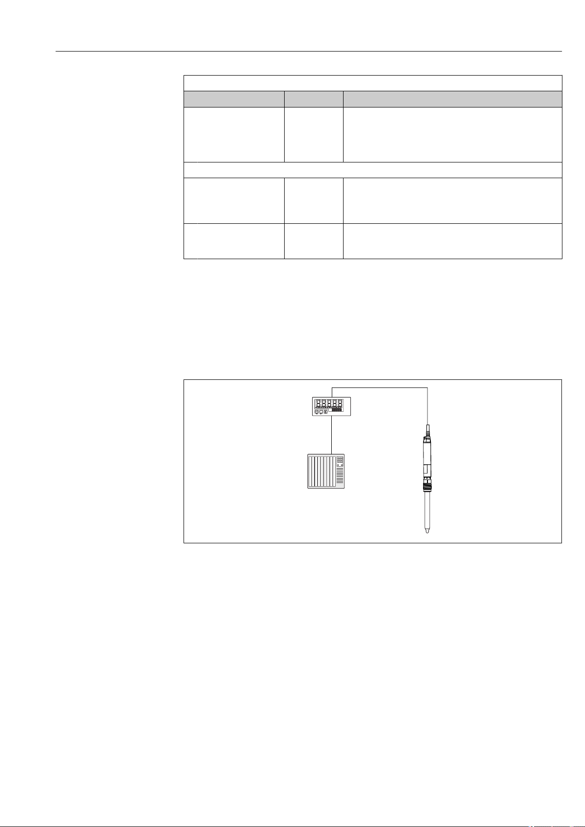
A0036208
13 Remote operation of CM82 via RIA15
1 PLC
2 RIA15 loop-powered process display unit
3 CM82 transmitter
4 Memosens sensor (e.g. pH sensor)
A 4 to 20mA (HART optional)
B 4 to 20mA with HART
Endress+Hauser 21
Page 22
Commissioning Liquiline Compact CM82
1
2
3
4
5
6
7
8
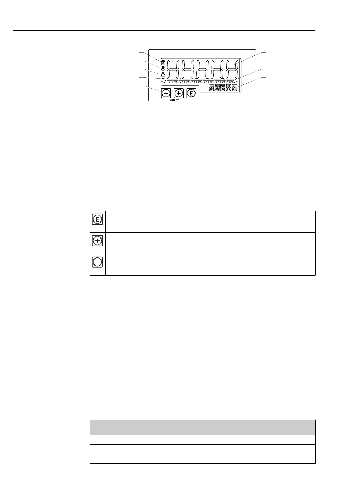
A0017719
14 Display and operating elements of the process display unit
1 Operating menu locked
2 Error
3 Warning
4 HART communication enabled
5 Operating keys "-", "+", "E"
6 14-segment display for unit/TAG
7 Bar graph with indicators for under range and over range
8 5-digit 7-segment display for measured value, digit height 17 mm (0.67 in)
The device is operated using three operating keys on the front of the housing.
The device setup can be disabled with a 4-digit user code. If the setup is disabled, a padlock
symbol appears on the display when an operating parameter is selected.
Enter key; calling up the operating menu, confirming the option/setting parameters in the operating
menu
A0017716
Selecting and setting/changing values in the operating menu; pressing the '-' and '+' keys simultaneously
takes the user back up a menu level. The configured value is not saved.
A0017715
A0017714
9.4.1 RIA15 operating matrix
In HART mode, the RIA15 with "Analysis" option can be used for basic configuration of the
Liquiline CM82.
The measuring ranges are dependent on the connected sensor and can be found in the
relevant sensor documentation.
Local measured value display and basic configuration of the CM82
The RIA15 can be used as a local indicator of the measured values as well as for basic
configuration of the Liquiline CM82 via HART®.
The following values are output here: Digital output (HART®): Measured value and unit
depending on the connected sensor
PV: Configured primary value (CMAIN operating parameter)
SV: Temperature (sensor)
TV: Dependent on the connected transmitter parameter + sensor type
QV: Dependent on the connected transmitter parameter + sensor type
Transmitter
parameter
pH Glass Raw value in mV Glass impedance in MOhm
pH ISFET Raw value in mV Leak current in nA
pH ORP Relative ORP value as % Raw value in mV
22 Endress+Hauser
Sensor type "TV" value "QV" value
Page 23
Liquiline Compact CM82 Commissioning
Transmitter
parameter
pH pH/ORP combined
Conductivity Resistance Conductivity, raw value
Dissolved oxygen Liquid concentration Saturation as %
Sensor type "TV" value "QV" value
pH ORP in mV
sensor
If "UC170" is displayed instead of the unit, see footnote in table.
The following settings for the CM82 can be made using the three operating keys on the
front of the RIA15:
• Units of connected sensor
• Current output range
• Retrieval of diagnostic information
Basic configuration of the CM82
The RIA15 must be in the HART mode (MODE = HART) to make the basic settings. The
ANALYSIS menu is not visible in analog mode (MODE = 4-20).
1. Press the key.
The Setup menu opens.
2. Press the key.
The CT submenu opens.
3. Set the desired parameters. For parameter descriptions, see the following table.
Setup -> ANALYSIS menu
The CT menu and all of the associated submenus are visible only if the RIA15 was ordered with the "Analysis" option, the HART option has been
configured and a CM82 has been detected by the RIA15. Using this menu, the basic settings for the CM82 can be made via the RIA15.
Parameter Values Description
CT This menu contains the parameters for configuring the CM82
compact transmitter.
CSET Access the "CM82 setup" submenu
TUNIT °C
°F
°K
OUTS Access the "CM82 - Output Setting" submenu to change the setting
pH glass sensors
CMAIN pH
mV_PH
IMPGL
TEMP
pH/ISFET sensors
CMAIN pH
mV_PH
LEAKC
TEMP
pH/ORP sensors
Select the unit for temperature on the CM82.
on the CM82.
The primary value (CMAIN) of the CM82 is assigned here and the
measuring range (4-20mA) configured.
Depending on the sensor type connected, only certain
measured values can be configured/displayed.
PH: pH measured value in pH
mV_PH: pH raw value in mV
IMPGL: Glass impedance in MOhm
TEMP: Temperature in °C/°F/K (unit as per setting in TUNIT)
PH: pH measured value in pH
mV_PH: pH raw value in mV
LEAKC: ISFET leak current in "nA"
TEMP: Temperature in °C/°F/K (unit as per setting in TUNIT)
1)
1)
Endress+Hauser 23
Page 24
Commissioning Liquiline Compact CM82
Setup -> ANALYSIS menu
The CT menu and all of the associated submenus are visible only if the RIA15 was ordered with the "Analysis" option, the HART option has been
configured and a CM82 has been detected by the RIA15. Using this menu, the basic settings for the CM82 can be made via the RIA15.
Parameter Values Description
CMAIN mVORP
%_ORP
TEMP
pH/ORP combined sensors
CMAIN pH
mV_PH
IMPGL
IMPRE
mVORP
%_ORP
RH
TEMP
Oxygen sensors
CMAIN PAR_P
%SAT
C_LIQ
C_GAS
CURR
RTIME
TEMP
UCLIQ
mG_L
uG_L
PPM
PPB
UCGAS
%_VOL
PPM_V
Conductivity sensors
CMAIN COND
RESIS
RAWC
TEMP
URES
KO*CM
MO*CM
KO*M
UCOND
uS/cm
mS/cm
S/cm
uS/m
mS/m
S/m
for all sensors
mVORP: ORP measured value in mV
%_ORP: Percentage ORP value as %
TEMP: Temperature in °C/°F/K (unit as per setting in TUNIT)
PH: pH measured value in pH
mV_PH: pH raw value in mV
IMPGL: Glass impedance in MOhm
1)
IMPRE: Reference impedance in Ohm
mVORP: ORP measured value in mV
%_ORP: Percentage ORP value as %
RH: rH value in rH
TEMP: Temperature in °C/°F/K (unit as per setting in TUNIT)
PAR_P: Partial pressure of oxygen in hPa
%SAT: Percentage saturation as %
C_LIQ: Liquid concentration (unit as per setting in UCLIQ)
C_GAS: Gas concentration (unit as per setting in UCGAS)
CURR: Raw value, measuring current of sensor in nA
1)
(visible only
in the case of amperometric oxygen sensors)
RTIME: Decay time, raw value in μs (visible only in the case of
optical oxygen sensors)
TEMP: Temperature in °C/°F/K (unit as per setting in TUNIT)
Unit of upper and lower turndown setting if the primary value
(CMAIN) is set to C_LIQ
mG_L: milligram/liter
1)
uG_L: microgram/liter
PPM: parts per million
PPB: parts per billion
Unit of upper and lower turndown setting if the primary value
(CMAIN) is set to C_GAS
%_VOL: percent by volume
PPM_V: parts per million
COND: specific conductivity (unit as per setting in UCOND)
RESIS: specific resistance (unit as per setting in URES)
RAWC: uncompensated conductivity (unit as per setting in UCOND)
TEMP: temperature (unit as per setting in TUNIT)
Unit of upper and lower turndown setting if the primary value
(CMAIN) is set to RESIS
KO*CM: kOhm*cm
MO*CM: MOhm*cm
KO*M: kOhm*m
Unit of upper and lower turndown setting if the primary value
(CMAIN) is set to COND or RESIS
uS/cm: microsiemens/cm
mS/cm: millisiemens/cm
S/cm: siemens/cm
uS/m: microsiemens/m
mS/m: millisiemens/m
S/m: siemens/m
24 Endress+Hauser
Page 25

Liquiline Compact CM82 Commissioning
Setup -> ANALYSIS menu
The CT menu and all of the associated submenus are visible only if the RIA15 was ordered with the "Analysis" option, the HART option has been
configured and a CM82 has been detected by the RIA15. Using this menu, the basic settings for the CM82 can be made via the RIA15.
Parameter Values Description
LOW -19,999 to
99,999
Configure turndown of current output. The measured value that
corresponds to 4 mA is set here. The limits of adjustment vary
depending on the sensor type and measured value. The position of
the decimal point is permanently preset depending on the primary
value (CMAIN) configured.
Valid ranges of adjustment:
pH sensor:
PH: -2.00 to 16.00 pH
mV_PH: -2000 to 2000 mV
LEAKC: -4000.0 to 4000.0 nA
IMPGL: 0 to 99999 MOhm
IMPRE: 0 to 99999 Ohm
mVORP: -2000 to 2000 mV
%_ORP: -3000.0 to 3000.0 %
RH: 0.0 to 70.0 rH
TEMP: -50.0 to 150.0 °C (depending on the unit configured under
TEMP)
-58.0 to 302.0°F
223.1 to 423.1 K
dissolved oxygen sensor:
PAR_P: 0.0 to 2500.0 hPa
%SAT: 0.02 to 200.00 % saturation
C_LIQ:
-0.02 to 120.00 mg/l
-20.00 to 999.99 ug/l
-0.02 to 120.00 ppm
-20.00 to 999.99 ppb
(depending on the unit configured in UCLIQ)
C_GAS:
-0.02 to 200 .00 % Vol
-0.02 to 200 .00 % Vol
-200.00 to 999.99 ppm Vol
(depending on the unit configured under UCGAS)
CURR: 0.0 to 9999.9 nA
RTIME: 0.0 to 100.0 µs
TEMP:
-10.0 to 140.0 °C
14.0 to 284 °F
263.1 to 413.1 K
(depending on the unit configured under TEMP)
Conductivity sensor:
COND:
0.000 to 99.999 uS/cm
0.000 to 99.999 mS/cm
0.000 to 2.000 S/cm
0.000 to 99.999 uS/m
0.000 to 99.999 mS/m
0.000 to 99.999 S/m
(depending on the unit configured in UCOND)
RESIS:
0.00 to 999.99 kOhm*cm
0.00 to 200.00 MOhm*cm
0.00 to 999.99 kOhm*m
(depending on the unit configured in URES)
RAWC:
0.000 to 99.999 uS/cm
0.000 to 99.999 mS/cm
0.000 to 2.000 S/cm
0.000 to 99.999 uS/m
0.000 to 99.999 mS/m
0.000 to 99.999 S/m
(depending on the unit configured in UCOND)
Endress+Hauser 25
Page 26

Commissioning Liquiline Compact CM82
Setup -> ANALYSIS menu
The CT menu and all of the associated submenus are visible only if the RIA15 was ordered with the "Analysis" option, the HART option has been
configured and a CM82 has been detected by the RIA15. Using this menu, the basic settings for the CM82 can be made via the RIA15.
Parameter Values Description
TEMP:
-50.0 to 250.0 °C
-58.0 to 482.0 °F
223.1 to 523.1 K
(depending on the unit configured under TEMP)
HIGH -19,999 to
99,999
ERRC 3.6 to 23.0 Configure the error current on the CM82 in mA
CDIAC Access the "CM82 - Device diagnostics" submenu
FCSM Error category as
per NAMUR and
error number
DTAG Device tag Display the device tag of the CM82 (use +/- keys to scroll through
DSER Device serial
number
SENOC Sensor order
code
SENSN Sensor serial
number
CTRES Access the "CM82 -Reset" submenu
RBOOT No
YES
FDEF No
YES
CTSIM Access the "CM82 -Simulation" submenu
SIMUL OFF
ON
VALUE 3.6 to 23.0 Configure current output value on CM82 for simulation in mA
Configure turndown of current output. The measured value that
corresponds to 20 mA is set here. The limits of adjustment vary
depending on the sensor type and measured value. The position of
the decimal point is permanently preset depending on the primary
value (CMAIN) and units (UCLIQ, UCGAS, URES, UCOND)
configured.
For valid ranges of adjustment, see LOW (setting for 4 mA)
Display the error message with the highest priority on the CM82
text)
Display the serial number of the CM82 (use +/- keys to scroll
through text)
Display the oder code of the sensor (use +/- keys to scroll through
text)
Display the serial number of the sensor (use +/- keys to scroll
through text)
Trigger a restart of the CM82
Reset the CM82 to factory settings
Switch on simulation for current output value on CM82
1) If "UC170" is displayed instead of unit. To remedy this, the unit must be set individually and manually in the "TEXT1" menu item. (SETUP => HART
=> HART1-4 => UNIT1-4 => TEXT1-4) → 26
Further information is available in the RIA15 Operating Instructions BA01170K.
"UC170" displayed instead of HART® unit
By default, the unit of the transmitted measured value is automatically read out and
displayed using a HART® command. If the transmitted "unit code" cannot be uniquely
assigned by the RIA15, the unit code (UC170) is displayed instead of the unit. To remedy
this, the unit must be set manually. (SETUP => HART => HART1-4 => UNIT1-4 =>
TEXT1-4).
26 Endress+Hauser
Page 27

Liquiline Compact CM82 Commissioning
The unit codes 170 to 219 are assigned multiple times as per the HART® specification. As
the UC170 is also used with the CM82, the unit must be assigned manually. This applies to
the following measured values/units:
PV (TEXT1):
Transmitter parameter Primary value (CMAIN) Unit
pH Leak current (LEAKC) nA
pH Glass impedance (IMPGL) MOhm
Dissolved oxygen Liquid concentration (C_LIQ) mg/l
Dissolved oxygen Raw value of sensor (CURR) nA
QV (TEXT4):
Transmitter parameter Sensor type Unit
pH Glass MOhm
pH ISFET nA
9.5 Setting the operating language
You can change the operating language in the app settings:
Settings/User interface/Language
9.6 Date and time
Configure the date and time under System/Date/Time .
The date and time function runs only while the device is supplied with power. They
must be reset if the power supply is interrupted.
(Start time: 01.01.1970 0:00 hours...)
9.7 Configuring the measuring device
Path: Application
Function Options Info
Units
Temperature unit Selection
• °C
• °F
• K
Factory setting
°C
Cond. unit Selection
• Automatic
• µS/cm
• mS/cm
• S/cm
• µS/m
• mS/m
• S/m
Factory setting
mS/cm
To be selected for conductivity
Endress+Hauser 27
Page 28

Commissioning Liquiline Compact CM82
Path: Application
Function Options Info
Conc. (liquid) unit Selection
• mg/l
• µg/l
• ppm
• ppb
Conc. (gaseous)
unit
Selection
• %vol
• ppm
To be selected for oxygen.
9.7.1 Changing the device tag
You can change the device tag here:
System/Device management/TAG
9.7.2 Configuring the sensor
Path: Application
Function Options Info
Sensor Sensor-dependent settings
Sensor type Display the sensor type
Order code Order code of sensor
Damping The damping causes a floating average curve of
the measured values over the time specified.
Damping ORP,
Damping pH,
Damping DO,
Damping conductivity
Damping temperature 0 to 60 s
Tag control
Sensor check Selection
Group Range: 0 to 65535
Extended setup
Conductivity:
Current cell constant Read only Value currently saved in the sensor
Compensation Selection
0 ... 60 s
Factory setting
0 s
Factory setting
0 s
• Off
• Tag
• Group
Factory setting
Off
• None
• Linear
• NaCl (IEC 746-3)
• Water ISO7888
(20 °C)
• Water ISO7888
(25°C)
Factory setting
Linear
These functions determine the damping of the
primary value of the connected sensor.
These functions determine the damping of the
integrated temperature sensor.
Various methods are available to compensate for
the temperature dependency. Depending on your
process, decide which type of compensation you
want to use.
Alternatively, you can also select None and thus
measure uncompensated conductivity.
28 Endress+Hauser
Page 29

Liquiline Compact CM82 Commissioning
Path: Application
Function Options Info
Meas. ref. temp. -5.0 to 100.0 °C
(23.0 to 212.0 °F)
Factory setting
25.0 °C (77.0 °F)
Factor alpha 0.000 to 20.000 %/K
Factory setting
2.100 %/K
pH:
Temp. compensation Selection
• Off
• Automatic
• Manual
Factory setting
Automatic
Medium comp. Selection
• Off
• 2-point calibration
• Table
Factory setting
Off
Offset -18.00 to 18.00 pH
-100 to 100 mg/l
Factory setting
0.00 pH
0.00 mg/l
Internal buffer pH 0 to 14
Factory setting
pH 7.00
Oxygen:
Medium pressure Selection
• Process pressure
• Air pressure
• Altitude
• Measured value
Factory setting
Air pressure
Air pressure Choose from
Medium pressure
Salinity Selection
• Fixed value
• Measured value
Factory setting
Fixed value
Reference temperature for calculating the
temperature-compensated conductivity
Enter the conductivity coefficient of your process
medium
Decide how you want to compensate the medium
temperature:
• Automatically using the temperature sensor of
your sensor (ATC)
• Manually by entering the medium temperature
• Not at all
Take a sample from the medium and determine
its pH value at different temperatures in the lab.
Decide whether you want to compensate using
two points or several points in a table.
The offset compensates for a difference between
a laboratory measurement and an online
measurement which is caused by interference
ions. Enter this value manually. If you are using a
compensation electrode, keep the offset at zero.
Only change the value if you are using a sensor
with an internal buffer other than pH 7.
Press Measured value you can connect a
pressure measured value via a fieldbus input or a
current input. This measured value is then used
for medium pressure compensation.
For the other types of compensation, specify a
compensation value for the measurement in each
case.
1. Specify either the altitude (-300 to
4000 m), the process pressure (500 to
9999 hPa) or the air pressure (500 to
1200 hPa) of the measuring point.
The pressure used during the
calibration is also displayed for
information purposes. You can change
this pressure in: Calib. settings/
Medium pressure.
2. Confirm.
Specify air pressure (500 to 9999 hPa) of
measuring point
Endress+Hauser 29
Page 30

Commissioning Liquiline Compact CM82
Path: Application
Function Options Info
Diagnostic settings For diagnostic settings of sensor, see
section→ 39
Format settings Number of decimal places
Calibration settings
Path: Application/Sensor/Extended setup/Calibration settings
Function Options Info
pH:
Stability criteria Once the stability criterion is met, the measured
value is displayed in mV.
Delta mV 0.20 to 2.00 %
Factory setting
0 %
Duration 0 ... 60 s
Factory setting
0 s
Temp. compensation Selection
• Off
• Automatic
• Manual
Factory setting
Automatic
Buffer recognition Selection
• Fixed
• Automatic
• Manual
Factory setting
Fixed
Buffer manufacturer Selection
• Endress+Hauser
• Ingold/Mettler
• DIN 19266
• DIN 19267
• Merck/Riedel
• Hamilton
• Special buffer
Factory setting
Endress+Hauser
Calibration buffer 1 ... 2 The possible options and the factory setting
Oxygen:
1)
Measured value depending on connected sensor
Decide how you want to compensate the buffer
temperature:
• Automatically using the temperature sensor of
your sensor (ATC)
• Manually by entering the medium temperature
• Not at all
Fixed
You choose values from a list. This list depends on
the setting for Buffer manufacturer.
Automatic
The device recognizes the buffer automatically.
The recognition depends on the setting for Buffer
manufacturer.
As their zero point is offset, enamel pH
sensors cannot be calibrated and adjusted
with automatic buffer recognition.
Manual
You enter any two buffer values. These must
differ in terms of their pH value.
Temperature tables are stored internally in the
unit for the following pH values:
• Endress+Hauser
2.00 / 4.00 / 7.00 / (9.00) / 9.22 / 10.00 /
12.00
• Ingold/Mettler
2.00 / 4.01 / 7.00 / 9.21
• DIN 19266
1.68 / 4.01 / 6.86 / 9.18
• DIN 19267
1.09 / 4.65 / 6.79 / 9.23 / 12.75
• Merck/Riedel
2.00 / 4.01 / 6.98 / 8.95 / 12.00
• Hamilton
1.09 / 1.68 / 2.00 / 3.06 / 4.01 / 5.00 / 6.00
7.00 / 8.00 / 9.21 / 10.01 / 11.00 / 12.00
depend on the Buffer manufacturer
30 Endress+Hauser
Page 31

Liquiline Compact CM82 Commissioning
Path: Application/Sensor/Extended setup/Calibration settings
Function Options Info
Stability criteria
Delta signal 0.1 to 2.0 %
Factory setting
0.2 %
Delta temperature 0.10 to 2.00 K
Factory setting
0.50 K
Duration 5 to 60 s
Factory setting
20 s
Ambient conditions
Medium pressure Selection
• Process pressure
• Air pressure
• Altitude
Factory setting
Air pressure
Process pressure
Medium pressure = Process
pressure
Air pressure
Medium pressure = Air
pressure
Altitude
Medium pressure = Altitude
Rel. hum. (air variable) 0 to 100 %
Calibration timer
Function Selection
Calibration check The function checks whether the calibration of a
Function Selection
500 to 9999 hPa
Factory setting
1013 hPa
500 to 1200 hPa
Factory setting
1013 hPa
-300 to 4000 m
Factory setting
0 m
Factory setting
100 %
• Off
• On
Factory setting
Off
• Off
• On
Factory setting
Off
Permitted measured value fluctuation during
calibration.
Referenced to the raw value in nA in the case of
amperometric sensors, and referenced to the raw
value in µS in the case of optical sensors.
Permitted temperature fluctuation during
calibration
Timeframe within which the permitted measured
value variation may not be exceeded
Enter the altitude or the average air pressure of
the place of calibration (mutually dependent
values).
If you specify the altitude, the average air
pressure is calculated from the barometric
altitude formula and vice versa.
If you are compensating using the process
pressure, enter the pressure in your calibration
medium here. The pressure is then independent
of the altitude.
sensor is still valid. Example: you install a precalibrated sensor. The function checks how long
ago the sensor was last calibrated. A diagnostics
message is displayed if the time since the last
calibration is longer than specified by the
predefined warning and alarm limit.
Endress+Hauser 31
Page 32

Commissioning Liquiline Compact CM82
Path: Application/Sensor/Extended setup/Calibration settings
Function Options Info
Warning limit 1 to 50 w
Factory setting
0 w
Alarm limit 1 to 50 w
Factory setting
0 w
1) Only pH sensor or pH/ORP combined sensor
Warning and alarm limits mutually influence
each other's possible adjustment range.
Warning and alarm limits mutually influence
each other's possible adjustment range.
9.7.3 Current output
Path: Application
Function Options Info
Current output
Output value pH, ISFET, ORP and
combined options
• pH
• Raw value pH
• Impedance glass
• Impedance reference
• rH
• ISFET Leakage current
• ORP mV
• ORP %
• Temperature
Oxygen options
• Partial pressure
• % saturation
• Conc. (liquid) unit
• Conc. (gaseous) unit
• Raw value µs
• Raw value nA
• Temperature
Conductivity options
• Conductivity
• Resistivity
• Raw value (cond.
uncomp.)
• Temperature
Range lower value (4mA) The unit depends on the
Range upper value (20mA)
sensor configured.
Depends on connected sensor
Enter the measuring range. The lower and
upper range values are assigned to the 3.6
mA value and the 20 mA value respectively.
The system uses the engineering unit which
you entered beforehand.
9.7.4 HART
Path Application/HART
Function Options Info
Bus address 0 to 63
Factory setting
0
PV value Choose from Current
output/Output value
Partial pressure Partial pressure dependence for oxygen
32 Endress+Hauser
Enter the bus address
Address 1 to 63 Multidrop - mode
Primary process value
Page 33

Liquiline Compact CM82 Commissioning
Path Application/HART
Function Options Info
SV value pH, ISFET, ORP and
TV value
QV value
combined units
• pH
• Raw value pH
• Impedance glass
• Impedance reference
• rH
• ISFET Leakage current
• ORP mV
• ORP %
• Temperature
Oxygen units
• Partial pressure
• % saturation
• Conc. (liquid) unit
• Conc. (gaseous) unit
• Raw value µs
• Raw value nA
• Temperature
Conductivity units
• Conductivity
• Resistivity
• Raw value (cond.
uncomp.)
• Temperature
Protocol-specific data, dynamic variables of
HART communication.
SV = Secondary
TV = Tertiary
QV = Quaternary
9.7.5 Hold
The hold state is a safe condition during configuration and calibration.
Path:System/Hold
Function Options Info
Hold release time 0 to 600 s
Factory setting
0 s
Hold behavior Selection
• None
• Freeze
• Fixed value
Factory setting
Freeze
Hold current 3.6 to 23 mA
Factory setting
0 mA
Manual hold Selection
• Off
• On
Factory setting
Off
Calibration hold Selection
• Off
• On
Factory setting
Off
The hold status is maintained for the
duration of the delay time when you
switch to the measuring mode.
On
You can use this function to set the
channel manually to "Hold".
Off
No channel-specific hold
During calibration, the output signal is set
to "HOLD"
Endress+Hauser 33
Page 34

Commissioning Liquiline Compact CM82
9.8 Configuration management
Display the following configurations:
System/System information
• General information
• HART
System/Sensor information
• General information
• Extreme values
• Sensor operation
• Sensor specifications
• Calibration information
– Temperature adjustment
– Primary value
9.9 Unauthorized access
The compact transmitter is password-protected against unauthorized access.
You can change this password immediately after the password has been entered or under:
System/Bluetooth password
9.9.1 Resetting the password
The recovery password is used to resolve password problems during commissioning of the
device. Data security is achieved only if the default setting for the recovery password is
changed by the user.
If the user-defined password is lost, access can be restored via a recovery password.
The recovery password is the serial number of the device in reverse.
NOTICE
Forgotten recovery password.
If lost, passwords can be reset via Bluetooth only if HART is used. The device cannot be
used if it does not have HART communication.
Ensure that the login and recovery password are stored in a safe place.
‣
9.9.2 Safe signal transmission via Bluetooth® LE
Signal transmission via Bluetooth® wireless technology uses a cryptographic
technique tested by the Fraunhofer Institute.
• Without the SmartBlue app, the device is not visible via Bluetooth® wireless technology.
• Only one point-to-point connection is established between a sensor and a smartphone or
tablet.
• The Bluetooth® wireless technology interface can be disabled via the SmartBlue.
• Bluetooth® is optional. It can be ordered with this functionality enabled.
If ordered with Bluetooth® disabled, Bluetooth® can be enabled at a later stage by means
of an activation code (accessory kit) linked to the serial number.
• If the Bluetooth® interface has been disabled, it can be reactivated only via HART.
9.9.3 RIA15 locking
The device setup can be disabled with a 4-digit user code.
Further information is available in the RIA15 Operating Instructions BA01170K.
34 Endress+Hauser
Page 35

Liquiline Compact CM82 Operation
10 Operation
10.1 Reading measured values
The display of the primary values in the app is dependent on the connected sensor.
HOME view
Function
Measurement values
For pH glass, ISFET, ORP or combined sensors:
pH
Raw value pH
Impedance glass
Impedance reference
ORP mV
ORP %
rH
Temperature
For oxygen sensors:
Partial pressure
% saturation
Conc. (liquid) unit
Conc. (gaseous)
Raw value nA
Raw value µs
Temperature
For conductivity sensors:
Conductivity
Resistivity
Raw value (cond. uncomp.)
Temperature
Current output
Data relating to the transmitter:
TAG
Device type
Serial number
Firmware version
Order code
10.1.1 Changing the parameters
The device functions according to the plug & play principle of Memosens technology.
Endress+Hauser 35
Page 36

Operation Liquiline Compact CM82
However, to ensure that the settings of the previous sensor type do not get lost, the new
sensor type must be selected in the software.
Path: Guidance/Measurement parameter
Function Options Info
Measurement parameter Selection
• pH
• Dissolved oxygen
• Conductivity
With "Finish" the device will be restarted and the measurement parameter change will be executed.
This may take a few minutes.
Select the parameters supported by the
device.
10.2 Adapting the measuring device to the process
conditions
10.2.1 Medium compensation (in the process) for oxygen
Path: Application/Sensor/Extended setup
Function Options Info
Medium pressure Selection
• Process pressure
• Air pressure
• Altitude
Salinity 0 to 40 g/kg
Factory setting
0 g/kg
Specify altitude (-300 to 4000 m),
process pressure (500 to 9999 hPa)
or air pressure (500 to 1200 hPa) of measuring
point
The influence of salt content on oxygen
measurement is compensated with this function.
Example: sea water measurement as per
Copenhagen Standard (30 g/kg).
36 Endress+Hauser
Page 37

Liquiline Compact CM82 Operation
10.2.2 LED settings (optical oxygen sensors only)
Path: Application/Sensor/Extended setup
Function Options Info
LED temp. mode Selection
• Off
• On
Factory setting
Off
LED temp. threshold 30 to 130 °C (86 to 266 °F)
Factory setting
80 °C (176 °F)
LED measuring interval Selection
• 1 second
• 3 seconds
• 10 seconds
• 30 seconds
Factory setting
1 second
Measurement filter Selection
• Off
• Weak
• Normal
• Strong
• Very strong
Switches off the LED when the set temperature
threshold is exceeded.
This prevents the premature aging of the sensor
cap, e.g. during a CIP or SIP cycle.
The LED measuring interval influences the
response time on the one hand and the
operating life of the sensor cap on the other.
Shorter intervals improve the response time but
reduce the operating life of the sensor cap.
Make your setting depending on the
requirements of your process.
Use this function to select how strong or weak
the signal filtering in sensor COS81D should be.
Off
No signal filtering takes place the recorded
signals are passed through virtually unfiltered.
Weak
Signal filtering is weak.
Normal
Signal filtering is normal.
Strong
Signal filtering is strong.
Very strong
Signal filtering is very strong. Widely fluctuating
raw signals are greatly attenuated by the sensor.
Endress+Hauser 37
Page 38

Diagnostics and troubleshooting Liquiline Compact CM82
11 Diagnostics and troubleshooting
11.1 Diagnostic information via LED
See LED display in Commissioning section. (→ 20)
11.2 Adapting the diagnostic information
Path: Diagnostics/Diagnostic settings
Function Options Info
Sensor change alarm delay 0 ... 180 s
Factory setting
30 s
Error current 3.6 to 23.0 mA
Factory setting
22.5 s
LED shows NAMUR status signal Selection
• Off
• On
Factory setting
Off
Diagnostics behavior The list of diagnostic messages
Status signal The messages are divided into
Diagnostics behavior Selection
• Warning
• Alarm
Sensor HOLD
Possible range of error current.
* Additional LED signals for
diagnostic messages as per
NAMUR NE107 categories.
displayed. There are devicespecific messages, and
messages that depend on what
sensor is connected.
Select the message to be
adapted. Only then can you
make the settings for this
message.
different error categories in
accordance with NAMUR NE
107.
* LED as per NAMUR NE107 categories:
Three rapid green flashes at the start of the message means: Everything OK - but pay
attention!
The more red flashes there are at the end of a message, the more critical the diagnosis as
per NE107. Continuous red only flashing means: Error in device or sensor, take action
immediately.
LED behavior Status
Three rapid green flashes and a single rapid red
flash
Three rapid green flashes and two rapid red flashes Device and sensor are being operated out of specification.
Three rapid green flashes and three rapid red
flashes
Red
Flashes quickly
Device or sensor requires maintenance.
M status signal as per NAMUR NE107
S status as per NAMUR NE107
Device or sensor undergoing function check.
C status signal as per NAMUR NE107
Failure of device or sensor
F status signal as per NAMUR NE107
38 Endress+Hauser
Page 39

Liquiline Compact CM82 Diagnostics and troubleshooting
11.3 Adapting sensor diagnostic information
This menu branch is used for specifying warning limits, and for defining whether and how
diagnostics tools should be used.
11.3.1 Impedance monitoring
Path: Application/Sensor/Extended setup/Diagnostic settings
Function Options Info
Glass impedance
Upper limit Selection
• Off
• On
Factory setting
Off
Upper limit Selection
• Off
• On
Factory setting
On
Upper alarm limit 0 to 10000 MΩ
Factory setting
3000 MΩ
Upper warning limit 0 to 10000 MΩ
Factory setting
2500 MΩ
Lower limit Selection
• Off
• On
Factory setting
Off
Lower limit Selection
• Off
• On
Factory setting
On
Lower warning limit 0 to 10000 MΩ
Factory setting
0.1 MΩ
Lower alarm limit 0 to 10000 MΩ
Factory setting
0 MΩ
On
The Sensor Check System (SCS)
operates with the following
settings for the upper warning
and alarm limits.
Off
Monitoring of the upper
warning and alarm limits is
switched off.
On
The Sensor Check System (SCS)
operates with the following
settings for the upper warning
and alarm limits.
Off
Monitoring of the upper
warning and alarm limits is
switched off.
Diagnostics code and associated
message text: 124 Sensor glass
Diagnostics code and associated
message text: 125 Sensor glass
On
The Sensor Check System (SCS)
operates with the following
settings for the lower warning
and alarm limits.
Off
Monitoring of the lower
warning and alarm limits is
switched off.
On
The Sensor Check System (SCS)
operates with the following
settings for the lower warning
and alarm limits.
Off
Monitoring of the lower
warning and alarm limits is
switched off.
Diagnostics code and associated
message text: 123 Sensor glass
Diagnostics code and associated
message text: 122 Sensor glass
Endress+Hauser 39
Page 40

Diagnostics and troubleshooting Liquiline Compact CM82
11.3.2 Slope
pH, oxygen
Path: Application/Sensor/Extended setup/Diagnostic settings
Function Options Info
pH
Slope The slope characterizes the
sensor condition. The greater
the deviation from the ideal
value (pH), the worse the
condition of the sensor.
Warning limit 5.00 to 99.00 mV/pH
Factory setting
55.00 mV/pH
Oxygen
Upper warning limit 0.0 to 200.0 %
Factory setting
140.0 %
Lower warning limit 0.0 to 200.0 %
Factory setting
60.0 %
Specify your limit values for
slope monitoring. Associated
diagnostic code and message
text: 509 sensor calibration
Associated diagnostics code and
message text: 511 Sensor
calibration
Associated diagnostics code and
message text: 509 Sensor
calibration
11.3.3 Delta slope
pH, pH/ORP combined sensor, oxygen
Path: Application/Sensor/Extended setup/Diagnostic settings
Function Options Info
pH and pH/ORP combined sensors
Delta slope The device determines the
difference in slope between the
last calibration and the
penultimate calibration, and
issues a warning or an alarm
depending on the setting
configured. The difference is an
indicator for the condition of
the sensor. The greater the
change, the greater the wear
experienced by the pH-sensitive
glass membrane as a result of
chemical corrosion or abrasion.
Function Selection
• Off
• On
Warning limit 0.10 to 10.00 mV/pH
Factory setting
5.00 mV/pH
Oxygen
Switches the function on or off
Specify your limit values for
monitoring the slope
differential.
Associated diagnostics code and
message text: 518 Sensor
calibration
40 Endress+Hauser
Page 41

Liquiline Compact CM82 Diagnostics and troubleshooting
Path: Application/Sensor/Extended setup/Diagnostic settings
Function Options Info
Delta slope The device determines the
difference in slope between the
last calibration and the
penultimate calibration, and
issues a warning or an alarm
depending on the setting
configured. The difference is an
indicator for the condition of
the sensor.
An increasing change indicates
the formation of buildup on the
sensor diaphragm or electrolyte
contamination. Replace the
diaphragm and electrolyte as
specified in the instructions in
the sensor operating manual.
Function Selection
• Off
• On
Factory setting
Off
Warning limit 0.0 to 50.0 %
Factory setting
5.0 %
Switches the function on or off
Specify your limit values for
monitoring the slope
differential.
Associated diagnostics code and
message text: 518 Sensor
calibration
11.3.4 Zero point and operating point
pH, ISFET, oxygen
Path: Application/Sensor/Extended setup/Diagnostic settings
Function Options Info
pH, ISFET
Zero point
(pH glass)
Operating point
(ISFET)
Upper warning limit Lower warning limit ...
pH 12.00
Lower warning limit ...
950 mV
1)
2)
Factory setting
pH 8.00 / 300 mV
Lower warning limit pH 2.00 to Upper warning
limit
-950 mV to Upper
warning limit
2)
Factory setting
pH 6.00 / ‐300 mV
Oxygen
The zero point or operating
point characterizes the
condition of the sensor
reference. The bigger the
deviation from the ideal value
(pH 7.00) the poorer the
condition. This can be caused by
KCl dissolving away or reference
contamination, for example.
Associated diagnostics code and
message text:
505 Sensor calibration
515 Sensor calibration
Associated diagnostics code and
message text:
507 Sensor calibration
517 Sensor calibration
2)
2)
Endress+Hauser 41
Page 42

Diagnostics and troubleshooting Liquiline Compact CM82
Path: Application/Sensor/Extended setup/Diagnostic settings
Function Options Info
Zero point The zero point corresponds to
the sensor signal that is
measured in a medium in the
absence of oxygen. You can
calibrate the zero point in water
that is free from oxygen or in
high-purity nitrogen. This
improves accuracy in the trace
range.
Warning limit 0.0 to 10.0 nA
Factory setting
3.0 nA
1) pH Glass
2) pH ISFET
Specify the limit values for zero
point monitoring in your sensor.
Associated diagnostics code and
message text: 513 Zero
Warning
11.3.5 Delta zero point/operating point
pH, ISFET, oxygen
Path: Application/Sensor/Extended setup/Diagnostic settings
Function Options Info
pH, ISFET
Delta zero point The device determines the
difference between the last
calibration and the penultimate
calibration, and issues a
warning or an alarm depending
on the setting configured. The
difference is an indicator for the
condition of the sensor.
Function Selection
• Off
• On
Warning limit pH 0.00 to 2.00 (pH glass)
Factory setting
pH 0.50 / 25 mV
Oxygen
Function Selection
• Off
• On
Factory setting
Off
Warning limit 0.0 to 10 nA
Factory setting
1.0 nA
Switches the function on or off
Specify your limit values for
monitoring the slope
differential.
Associated diagnostics code and
message text:
• 520 Sensor calibration (pH
glass)
• 522 Sensor calibration
(ISFET)
Switches the function on or off
Specify your limit values for
monitoring the slope
differential.
Associated diagnostics code and
message text: 520 Sensor
calibration
42 Endress+Hauser
Page 43

Liquiline Compact CM82 Diagnostics and troubleshooting
11.3.6 Operating hours limits
Path: Application/Sensor/Extended setup/Diagnostic settings
Function Options Info
Limits operating hours The total operating time of the
sensor and its use under
extreme conditions is
monitored. If the operating time
exceeds the defined threshold
values, the device issues a
corresponding diagnostics
message.
Function Selection
• Off
• On
Operating time Factory setting
60000 h
Operating time > 80 °C Factory setting
50000 h
Operating time > 80 °C < 100 nS/cm Factory setting
30000 h
Operating time > 100 °C Factory setting
50000 h
Operating time > 120 °C Factory setting
10000 h
Operating time > 150 °C Factory setting
10000 h
Operating time < -300 mV Factory setting
60000 h
Operating time > 300 mV Factory setting
60000 h
On
The operation of the sensor
under extreme conditions is
monitored, recorded in the
sensor and diagnostics
messages are displayed on the
controller.
Off
No diagnostics messages.
However, the time the sensor
operates under extreme
conditions is recorded in the
sensor and can be read in the
sensor information in the
diagnostics menu.
Diagnostics code and associated
message text: 193 Operating
time
Only conductive sensors
Diagnostics code and associated
message text: 194 Operating
time
Diagnostics code and associated
message text: 195 Operating
time
Diagnostics code and associated
message text: 198 Operating
time
Only pH sensor or pH/ORP
combined sensor
Only pH sensor or pH/ORP
combined sensor
Endress+Hauser 43
Page 44

Diagnostics and troubleshooting Liquiline Compact CM82
11.3.7 Sterilizations
Path: Application/Sensor/Extended setup/Diagnostic settings
Function Options Info
Sterilizations The system counts the number
of operating hours in which the
sensor is exposed to a
temperature that is typical for a
sterilization. This temperature
depends on the sensor.
Function Selection
• Off
• On
Warning limit 0 to 1000
Factory setting
800
Cap sterilizations (only sterilizable sensors)
Switches the function on or off
Specify the limit value for the
number of sensor sterilizations.
Diagnostics code and associated
message text: 108 SIP, CIP,
autoclaving
Path: Application/Sensor/Extended setup/Diagnostic settings
Function Options Info
No. sterilizations cap Not displayed for optical oxygen
sensors.
The sterilization counters in the
sensor make a distinction
between the sensor and the
membrane/fluorescence cap
currently used. If this cap is
replaced, only the (cap) counter
is reset.
Function Selection
• Off
• On
Factory setting
Off
Warning limit 0 to 100
Factory setting
25
Specify how many sterilizations
may be performed with a
membrane cap before the cap
has to be replaced. The number
depends heavily on the process
and must be determined
individually.
Associated diagnostics code and
message text: 109 Sterilization
cap
44 Endress+Hauser
Page 45

Liquiline Compact CM82 Diagnostics and troubleshooting
11.3.8 Sensor Condition Check (SCC)
Path: Application/Sensor/Extended setup/Diagnostic settings
Function Options Info
Sensor condition check Sensor condition check (SCC)
monitors the electrode status
and the degree of electrode
aging. The condition of the
electrode is updated after every
calibration.
The main reasons for a
deteriorating electrode status
are:
• Glass membrane blocked or
dry
• Diaphragm (reference)
blocked
Function Selection
• Off
• On
Switches the function on or off
Diagnostics code and associated
message text:
127 SCC adequate
126 SCC poor
11.3.9 Process monitoring
Path: Application/Sensor/Extended setup/Diagnostic settings
Function Options Info
Process check system The process check system (PCS)
checks the measuring signal for
stagnation. An alarm is
triggered if the measuring
signal does not change over a
specific period (several
measured values).
Function Selection
Duration 0 to 240 min Once this time has elapsed, the
Tolerance width
Not for pH/ORP sensors
• Off
• On
The range depends on the
sensor
Factory setting
Depends on the sensor
Switches the function on or off
calibration timer diagnostic
message, along with the code
102, appears on the display.
Interval around the measuring
signal (raw value) for detecting
stagnation.
Measured values within the set
interval are regarded as
stagnating.
11.3.10 Measured value
Path: Application/Sensor/Extended setup/Diagnostic settings
Function Options Info
ORP-Meas value
Function Selection
• Off
• On
Upper alarm value 0 to 10000 mV Diagnostics code and associated
Endress+Hauser 45
Switches the function on or off
message text: 124 Sensor glass
Page 46

Diagnostics and troubleshooting Liquiline Compact CM82
Path: Application/Sensor/Extended setup/Diagnostic settings
Function Options Info
Upper warning limit 0 to 10000 mV Diagnostics code and associated
message text: 125 Sensor glass
Lower warning limit 0 to 10000 mV Diagnostics code and associated
message text: 123 Sensor glass
Lower alarm value 0 to 10000 mV Diagnostics code and associated
message text: 122 Sensor glass
11.3.11 Pharmaceutical water
Path: Application/Sensor/Extended setup/Diagnostic settings
Pharma water Here you can make settings for
monitoring pharmaceutical
water in accordance with the
United States Pharmacopoeia
(USP) or European
Pharmacopoeia (EP).
The uncompensated
conductivity value and the
temperature are measured for
the limit functions. The
measured values are compared
against the tables defined in the
standards. An alarm is triggered
if the limit value is exceeded.
Furthermore, you can also set a
preliminary alarm (warning
limit) which signals undesired
operating states before they
occur.
Function Selection
• Off
• EP
• USP
Factory setting
Off
Off 10.0 to 99.9 %
Factory setting
80.0 %
The alarm values are stored in
the device in accordance with
USP <645> or EP <169>
specifications.
You define the warning limit as
a % of the alarm value.
Diagnostics code and associated
message text: 915 USP / EP
warning
If the value exceeds the USP or
EP alarm values saved in the
software, diagnostics message
914 USP/ EP alarm is
displayed.
46 Endress+Hauser
Page 47

Liquiline Compact CM82 Diagnostics and troubleshooting
11.3.12 Cap calibrations
Path: Application/Sensor/Extended setup/Diagnostic settings
Function Options Info
No. calibrations cap Not displayed for optical oxygen
sensors
The calibration counters in the
sensor make a distinction
between sensor calibrations and
calibrations with the membrane
cap currently used. If this cap is
replaced, only the (cap) counter
is reset.
Function Selection
• Off
• On
Factory setting
Off
Warning limit 0 to 1000
Factory setting
6
Specify how many calibrations
may be performed with a
membrane cap before the cap
has to be replaced. The number
depends heavily on the process
and must be determined
individually.
Associated diagnostics code and
message text: 535 Sensor
check
11.3.13 Calibration quality index (optical sensors only)
Path: Application/Sensor/Extended setup/Diagnostic settings
Function Options Info
Cal. quality index Monitoring of calibration
quality index for COS81D.
Significant changes in the value
may be a sign of spot aging or
poor calibration.
Function Selection
• Off
• On
Factory setting
Off
Warning limit 0 ... 100 %
Factory setting
80 %
Switches the function on or off
Associated diagnostics code and
message text: 734 Calibration
quality
11.4 Simulation
You can simulate certain parameters for test purposes:
• Current value
• Measured value
• Temperature
Endress+Hauser 47
Page 48

Diagnostics and troubleshooting Liquiline Compact CM82
Main menu/Diagnostics/Simulation
Function Options Info
Current output Simulation of an output current
Simulation Selection
• Off
• On
Factory setting
Off
Simulation value Unit:
Window:
Measurement value Simulation of a measured value
Simulation Selection
• Off
• On
Factory setting
Off
Measured value Select measured variable to be
Simulation value Unit:
Window:
Temperature Simulation of temperature
Simulation Selection
• Off
• On
Factory setting
Off
Simulation value Unit:
Window:
Switch on or off simulation
Set current value
Switch on or off simulation
simulated, depending on
connected sensor.
Display the simulated measured
value in the selected unit.
Switch on or off simulation
Display the simulated
temperature value in the
selected unit
11.5 Diagnostic list
11.5.1 Diagnostic messages
In accordance with Namur specification NE 107, the diagnostic messages are characterized
by:
• Message number
• Error category (letter in front of the message number)
– F = (Failure) a malfunction has been detected
– C = (Function check), (no error)
Maintenance work is being performed on the device. Wait until the work has been
completed.
– S = (Out of specification), the measuring point is being operated outside its
specification
Operation is still possible. However, you run the risk of increased wear, shorter
operating life or lower measurement accuracy. The cause of the problem is to be found
outside the measuring point.
– M = (Maintenance required), action should be taken as soon as possible
• Sensor type:
– P = ph
– C = conductivity
– O = oxygen
• Message text
48 Endress+Hauser
Page 49

Liquiline Compact CM82 Diagnostics and troubleshooting
No. Message Factory settings Sensor
type
1)
S
002 Sensor
unknown
004 Sensor defective F On On All
005 Sensor data
invalid
010 Sensor scanning F Off Off All No
012 Writing data
failed
013 Sensor type
wrong
018 Sensor not
ready
022 Temperature
sensor
061 Sensor
electronic
062 Sensor
connection
100 Sensor
communication
102 Calibration
timer
104 Calibration
validity
F On On All No
F On On All No 1. Check the firmware
F On On All No 1. Repeat write process.
F On On All No
F On On All No Sensor communication
F On On All Yes Temperature sensor defective
F On On All No Sensor electronics defective
F On On All No 1. Check sensor
F On On All No Sensor not communicating
M On Off All Yes Calibration interval elapsed.
M On Off All Yes Last calibration no longer
2)
D
3)
F
ConfigurableTests or remedial action
Replace sensor.
‣
compatibility of the
sensor and transmitter
or load suitable
firmware
2. Set the sensor to the
factory settings,
disconnect the sensor
and reconnect it.
3. Update transmitter
data
4. Replace sensor.
Wait for initialization to
‣
be finished.
2. Replace sensor.
Replace sensor, making
‣
sure correct sensor type
is used.
blocked
1. Sensor fails tag check.
Replace.
2. Internal software
error. Contact the
Service Department.
Replace sensor.
‣
Replace sensor.
‣
connection.
2. Contact the Service
Department.
1. Check sensor
connection.
2. Check sensor
connector.
3. Contact the Service
Department.
Measurement can still take
place.
Calibrate sensor.
‣
valid. Measurement can still
take place.
Calibrate sensor.
‣
Endress+Hauser 49
Page 50

Diagnostics and troubleshooting Liquiline Compact CM82
No. Message Factory settings Sensor
type
1)
S
105 Calibration
validity
106 Sensor TAG F On On All No Sensor has invalid tag or tag
107 Calibration
active
108 SIP, CIP,
autoclaving
109 Sterilization cap M On Off O No Specified number of
111 Operating time
cap
118 Sensor glass
break.
119 Sensor check M On Off P (glass) No
120 Sensor
reference
121 Sensor
reference
M On Off All Yes Last calibration will lose its
C On Off All No
M On Off O Yes Specified number of
M On Off O No Hours of operation
F On Off P (glass) Yes Glass breakage warning,
F On Off P (glass) Yes Reference warning,
M On Off P (glass) No
2)
D
3)
F
ConfigurableTests or remedial action
validity soon. Measurement
can still take place.
Calibrate sensor.
‣
group
Wait for calibration to be
‣
finished.
sterilizations will soon be
reached. Measurement can
still take place.
Replace sensor.
‣
sterilizations for the cap is
reached. Measurement can
still take place.
Replace membrane cap.
‣
monitoring
The limit set for the total
hours of operation for the
cap has been reached.
Measurement can still take
place.
1. Replace the cap.
2. Change monitoring
limit.
impedance of pH glass too
low
Measuring can continue until
the alarm (118) occurs.
1. Inspect sensor for
hair-line cracks and
breakage.
2. Check medium
temperature.
3. Replace sensor.
impedance of reference too
low
Measuring can continue until
the alarm (120) occurs.
1. Check reference for
clogging/
contamination.
2. Clean reference/
junction.
3. Replace sensor.
50 Endress+Hauser
Page 51

Liquiline Compact CM82 Diagnostics and troubleshooting
No. Message Factory settings Sensor
ConfigurableTests or remedial action
type
1)
S
2)
D
3)
F
122 Sensor glass F On Off P (glass) Yes Impedance limit values
123 Sensor glass M On Off P (glass) Yes
124 Sensor glass M On Off P (glass) Yes
125 Sensor glass F On Off P (glass) Yes
exceeded/undershot
Measuring can continue until
the alarm (122, 124) occurs.
1. Inspect sensor for
hair-line cracks and
breakage.
2. Check or change limit
values.
3. Replace sensor.
126 Sensor check M On Off P (glass) No Sensor condition check (SCC),
poor sensor condition
Glass membrane fouled or
dry, junction blocked
1. Clean sensor,
regenerate
2. Replace sensor.
127 Sensor check M On Off P (glass) No Sensor condition check (SCC),
adequate sensor condition
128 Sensor leakage F On Off P (ISFET),
O
Yes Leak current alarm
Defective due to abrasion or
damage
Damage to the gate (only
ISFET)
Replace sensor.
‣
129 Sensor leakage F On Off P (ISFET),
DO
Yes Leak current warning
Measuring can continue until
the alarm occurs
130 Sensor supply F On Off P, O Yes Poor sensor power supply
1. Check sensor
connection.
2. Replace sensor.
131 Sensor
calibration
132 Sensor
calibration
M On Off O No Limit values for sensor
relaxation time (fluorescence
M On Off O
decay time) exceeded/
undershot
Reasons: high oxygen
content, incorrect calibration
1. Repeat calibration.
2. Replace sensor cap.
3. Contact the Service
Department.
133 Sensor signal F On Off O No No signal (fluorescence
decay)
1. Replace sensor cap.
2. Contact the Service
Department.
Endress+Hauser 51
Page 52

Diagnostics and troubleshooting Liquiline Compact CM82
No. Message Factory settings Sensor
type
1)
S
134 Sensor signal M On Off O No Low signal amplitude.
136 Sensor temp.
high
141 Polarization F On Off C No Polarization warning
142 Sensor signal F On Off C No Reasons: sensor in air, sensor
146 Sensor
temperature
154 Sensor data
invalid
160 Sensor data
invalid
164 Sensor data
invalid
168 Polarization S On Off C (cond.) No Polarization warning
S On Off O No Temperature outside
S Off Off All Yes Temperature outside
M Off Off C No Factory calibration is used
F On Off All No No calibration data
M Off Off C No No temperature calibration
2)
D
3)
F
ConfigurableTests or remedial action
Measurement can still take
place.
1. Replace sensor cap.
2. Contact the Service
Department.
specification
1. Check process.
2. Check installation.
The measured value is
corrupted at high
conductivity levels.
Use a sensor with a
‣
larger cell constant.
defective
1. Check installation.
2. Replace sensor.
specification
1. Check the
temperature.
2. Check electrode
system.
3. Replace sensor type.
Calibrate.
‣
Reasons: data deleted
1. Select other data
record.
2. Use factory
calibration.
3. Contact the Service
Department.
data
Factory calibration is used
1. Check process.
2. Check or replace
sensor.
The measured value is
corrupted at high
conductivity levels.
Use a sensor with a
‣
larger cell constant.
52 Endress+Hauser
Page 53

Liquiline Compact CM82 Diagnostics and troubleshooting
No. Message Factory settings Sensor
ConfigurableTests or remedial action
type
1)
S
2)
D
3)
F
178 Operating time M On Off All No Operating hours > 15 °C,
measurement can still take
place
1. Replace sensor.
2. Change monitoring
limit.
3. Disable monitoring.
179 Operating time M On Off P No Operating hours > 300 mV,
measurement can still take
place
1. Replace sensor.
2. Change monitoring
limit.
3. Disable monitoring.
180 Operating time M On Off P No Operating hours < -300 mV,
measurement can still take
place
1. Replace sensor.
2. Change monitoring
limit.
3. Disable monitoring.
183 Operating time M On Off O (amp.) No Operating hours > 10 nA
(COS51D), measurement can
still take place
1. Replace sensor.
2. Change monitoring
limit.
3. Disable monitoring.
184 Operating time M On Off O (amp.) No Operating hours > 30 nA
(COS22D), measurement can
still take place
1. Replace sensor.
2. Change monitoring
limit.
3. Disable monitoring.
185 Operating time M On Off O (amp.) No Operating hours > 40 nA
(COS51D), measurement can
still take place
1. Replace sensor.
2. Change monitoring
limit.
3. Disable monitoring.
186 Operating time M On Off O (amp.) No Operating hours > 160 nA
(COS22D), measurement can
still take place
1. Replace sensor.
2. Change monitoring
limit.
3. Disable monitoring.
Endress+Hauser 53
Page 54

Diagnostics and troubleshooting Liquiline Compact CM82
No. Message Factory settings Sensor
ConfigurableTests or remedial action
type
1)
S
2)
D
3)
F
187 Operating time M On Off C No Operating hours > 80 °C, 100
nS/cm, measurement can
still take place
1. Replace sensor.
2. Change monitoring
limit.
3. Disable monitoring.
189 Operating time M On Off O No Operating hours > 5 °C,
measurement can still take
place
1. Replace sensor.
2. Change monitoring
limit.
3. Disable monitoring.
191 Operating time M On Off O No Operating hours > 30 °C,
measurement can still take
place
1. Replace sensor.
2. Change monitoring
limit.
3. Disable monitoring.
192 Operating time M On Off O No Operating hours > 40 °C,
measurement can still take
place
1. Replace sensor.
2. Change monitoring
limit.
3. Disable monitoring.
193 Operating time M On Off P, C, O No Operating hours > 80 °C,
measurement can still take
place
1. Replace sensor.
2. Change monitoring
limit.
3. Disable monitoring.
194 Operating time M On Off P No Operating hours > 100 °C,
measurement can still take
place
1. Replace sensor.
2. Change monitoring
limit.
3. Disable monitoring.
195 Operating time M On Off C No Operating hours > 120 °C,
measurement can still take
place
1. Replace sensor.
2. Change monitoring
limit.
3. Disable monitoring.
54 Endress+Hauser
Page 55

Liquiline Compact CM82 Diagnostics and troubleshooting
No. Message Factory settings Sensor
ConfigurableTests or remedial action
type
1)
S
2)
D
3)
F
197 Operating time M On Off C No Operating hours > 140 °C,
measurement can still take
place
1. Replace sensor.
2. Change monitoring
limit.
3. Disable monitoring.
198 Operating time M On Off C No Operating hours > 150 °C,
measurement can still take
place
1. Replace sensor.
2. Change monitoring
limit.
3. Disable monitoring.
199 Operating time M On Off All No Total operating hours
202 Self-test active F On On All No Self-test active, please wait
215 Simulation
active
C On Off All No Simulation active
End simulation by changing
to measuring mode.
216 Hold active C On Off All No HOLD active - output values
and channel status are on
hold
Please wait
‣
241 Firmware error F On On All No Software error - internal
1. Carry out software
update
2. Replace backplane
please
3. Please contact the
Service Department
and quote the number
shown
243 Firmware error F On On All No Software error - internal
1. Carry out software
update
2. Replace backplane
please
3. Please contact the
Service Department
and quote the number
shown
284 Firmware
update
F On On All No Firmware update active,
please wait.
285 Update error F On On All No Firmware update failed,
possible reasons:
• Read error
• SD card is faulty
• Incorrect firmware on SD
card
1. Check device settings
2. Check electronics
module type
Endress+Hauser 55
Page 56

Diagnostics and troubleshooting Liquiline Compact CM82
No. Message Factory settings Sensor
type
1)
S
373 Temperature of
electronics is
high
384 Firmware error F On On All No Sensor measuring sequence
408 Calibration
aborted
411 Up-/Download
active, please
wait
460 Output
undershot
461 Output overshot S On Off All No Current output overshot
500 Sensor
calibration
M On Off All No Temperature of backplane
M Off Off P, C, O, No Calibration aborted
C On Off All No Up-/download active
S On Off All No Current output undershot
M On Off All No Calibration aborted, main
2)
D
3)
F
ConfigurableTests or remedial action
electronics is high
Check ambient
‣
temperature and energy
consumption
counter. No measurement
signal from sensor
1. Update software
2. Contact the Service
Department
Please wait
‣
Measured value out of
specified current range,
possible reasons:
• Sensor / sample line in air
• Air pockets in the
assembly
• Incorrect flow to sensor
• Sensor / sample line is
contaminated
1. Check sensor.
2. Check application.
3. Check application.
4. Clean sensor / sample
line.
Measured value out of
specified current range,
possible reasons:
• Sensor / sample line in air
• Air pockets in the
assembly
• Incorrect flow to sensor
• Sensor / sample line is
contaminated
1. Check sensor.
2. Check application.
3. Check application.
4. Clean sensor / sample
line.
measured value varies
Reasons: sensor too old,
sensor occasionally dry,
calibration value not constant
1. Check sensor.
2. Check calibration
solution.
56 Endress+Hauser
Page 57

Liquiline Compact CM82 Diagnostics and troubleshooting
No. Message Factory settings Sensor
type
501 Sensor
1)
S
M On Off All No Calibration aborted,
2)
D
3)
F
calibration
505 Sensor
M On Off P, O No Max. zero point warning,
calibration
507 Sensor
M On Off P, O No Min. zero point warning,
calibration
509 Sensor
M On Off P, O No Min. slope warning,
calibration
ConfigurableTests or remedial action
temperature measured value
varies
Reasons: sensor too old,
sensor occasionally dry,
temperature of calibration
solution not constant
1. Check sensor.
2. Regulate calibration
solution temperature.
measurement can still take
place
Possible reasons: sensor old
or defective, reference
blocked, calibration solution
too old or contaminated
1. Check or replace
sensor.
2. Check or replace
calibration solution.
3. Repeat calibration.
measurement can still take
place
Possible reasons: sensor old
or defective, reference
blocked, calibration solution
too old or contaminated
1. Check or replace
sensor.
2. Check or replace
calibration solution.
3. Repeat calibration.
measurement can still take
place
Possible reasons: sensor old
or defective, reference
blocked, calibration solution
too old or contaminated
1. Check or replace
sensor.
2. Check or replace
calibration solution.
3. Repeat calibration.
Endress+Hauser 57
Page 58

Diagnostics and troubleshooting Liquiline Compact CM82
No. Message Factory settings Sensor
ConfigurableTests or remedial action
type
511 Sensor
calibration
1)
S
M On Off P, O No Max. slope warning,
2)
D
3)
F
measurement can still take
place
Possible reasons: sensor old
or defective, reference
blocked, calibration solution
too old or contaminated
1. Check or replace
sensor.
2. Check or replace
calibration solution.
3. Repeat calibration.
513 Zero Warning M On Off O (amp.) No Zero point warning,
measurement can still take
place
Possible reasons: sensor old
or defective, reference
blocked, calibration solution
too old or contaminated
1. Check or replace
sensor.
2. Check or replace
calibration solution.
3. Repeat calibration.
515 Sensor
calibration
M On Off P (ISFET) No Max. operating point
warning, measurement can
still take place
Possible reasons: sensor old
or defective, reference
blocked, calibration solution
too old or contaminated
1. Check or replace
sensor.
2. Check or replace
calibration solution.
3. Repeat calibration.
517 Sensor
calibration
M On Off P (ISFET) No Min. operating point
warning, measurement can
still take place
Possible reasons: sensor old
or defective, reference
blocked, calibration solution
too old or contaminated
1. Check or replace
sensor.
2. Check or replace
calibration solution.
3. Repeat calibration.
58 Endress+Hauser
Page 59

Liquiline Compact CM82 Diagnostics and troubleshooting
No. Message Factory settings Sensor
ConfigurableTests or remedial action
type
518 Sensor
calibration
1)
S
M On Off P, O No Delta slope warning,
2)
D
3)
F
measurement can still take
place
Possible reasons: sensor old
or defective, reference
blocked, calibration solution
too old or contaminated
1. Check or replace
sensor.
2. Check or replace
calibration solution.
3. Repeat calibration.
520 Sensor
calibration
M On Off P, O No Delta zero point warning,
measurement can still take
place
Possible reasons: sensor old
or defective, reference
blocked, calibration solution
too old or contaminated
1. Check or replace
sensor.
2. Check or replace
calibration solution.
3. Repeat calibration.
522 Sensor
calibration
M On Off P (ISFET) No Delta operating point
warning, measurement can
still take place
Possible reasons: sensor old
or defective, reference
blocked, calibration solution
too old or contaminated
1. Check or replace
sensor.
2. Check or replace
calibration solution.
3. Repeat calibration.
532 License error M On Off All No License error
534 Electrolyte
warning
M On Off All No Electrolyte depletion warning
The configured electrolyte
depletion limit has been
reached. Measurement is still
possible.
1. Replace electrolyte
and, if necessary, the
membrane cap.
2. Reset counter for CAL
3. Replace electrolyte, or
replace sensor cap and
electrolyte.
4. Replace sensor
535 Sensor check M On Off O (amp.) No Specified number of cap
calibrations is reached
Measurement can still take
place.
Replace sensor cap.
‣
Endress+Hauser 59
Page 60

Diagnostics and troubleshooting Liquiline Compact CM82
No. Message Factory settings Sensor
type
550 Process
temperature
551 Process
temperature
552 Conductivity
low
553 Conductivity
high
554 Concentration
low
555 Concentration
high
722 Sensor
reference
723 Sensor
reference
724 Sensor
reference
725 Sensor
reference
1)
S
S On Off C No Process temperature above/
S On Off C
S On Off C No Process concentration above/
S On Off C
S On Off C No Process concentration above/
S On Off C
F On On P Yes Alarm: Reference membrane
M On Off All Yes Warning: Reference
F On On All Yes Alarm: Reference membrane
M On Off All Yes Warning: Reference
2)
D
3)
F
ConfigurableTests or remedial action
below concentration table
• Process value outside
specification
• Table incomplete
Extend table.
‣
below concentration table
• Process value outside
specification
• Table incomplete
Extend table.
‣
below concentration table
• Process value outside
specification
• Table incomplete
Extend table.
‣
impedance too low.
1. Check or replace
sensor.
2. Check/correct
reference limit value.
membrane impedance too
low.
Can continue measuring until
the alarm occurs.
1. Check or replace
sensor.
2. Check/correct
reference limit value.
impedance too high.
1. Check or replace
sensor.
2. Check/correct
reference limit value.
membrane impedance too
high.
Can continue measuring until
the alarm occurs.
1. Check or replace
sensor.
2. Check/correct
reference limit value.
60 Endress+Hauser
Page 61

Liquiline Compact CM82 Diagnostics and troubleshooting
No. Message Factory settings Sensor
ConfigurableTests or remedial action
type
734 Calibration
quality
1)
S
M On Off All No Min. Calibration quality
2)
D
3)
F
warning Measurement is still
possible. There is a
significant change in
calibration quality since the
last calibration.
1. Repeat the calibration
2. Check sensor and
replace if necessary
740 Sensor defective F On On C No Internal electrode failure
1. Replace sensor.
2. Contact the Service
Department.
832 Temp. range
exceeded
S Off Off All Yes Outside temperature
specification
1. Check application.
2. Check temperature
sensor.
841 Operating range S Off Off All Yes Process value outside
operational range
1. Check application.
2. Check sensor.
842 Process value S Off Off P Yes Process limit value exceeded/
843 Process value S Off Off P
undershot
Reasons: sensor in air, air
pockets in assembly,
incorrect flow to sensor,
sensor defective
1. Change process value.
2. Check electrode
system.
3. Change sensor type.
904 Process check
alarm
F On On All No Stagnating measuring signal
Reasons: sensor in air, sensor
fouling, incorrect flow to
sensor, sensor defective
1. Check electrode
system.
2. Check sensor.
3. Restart the device.
910 Limit switches S On Off No Limit switch activated
914 USP/ EP alarm M On Off C Yes USP limit values exceeded
Check process.
915 USP / EP
M On Off C
‣
warning
942 Process value S Off Off P No Process value high
1. Do not increase
process value.
2. Check electrode
system.
3. Change sensor type.
Endress+Hauser 61
Page 62

Diagnostics and troubleshooting Liquiline Compact CM82
No. Message Factory settings Sensor
type
1)
S
943 Process value S Off Off P No Process value low
987 Calibration
required
1) Status signal
2) Diagnostic message
3) Error current
M On On I, DI No Electrode replacement
2)
D
3)
F
ConfigurableTests or remedial action
1. Do not decrease
process value.
2. Check electrode
system.
3. Change sensor type.
Calibrate sensor.
‣
11.6 Event logbook
Main menu/Diagnostics/Diagnostics logbook
Function Info
Time Time when diagnostic message occurred.
Event Indicate whether message is going or coming.
Status signal Error category and fault elimination
11.7 Resetting the measuring device
Path: System/Device management/Reset
Function Options Info
Device restart Press Finish to start the
application
Press X to close the wizard
without running it and to
go back.
Factory default Press Finish to start the
application
Press X to close the wizard
without running it and to
go back.
Restart and keep all the settings
Restart with factory settings
Settings that have not been
saved are lost.
62 Endress+Hauser
Page 63

Liquiline Compact CM82 Diagnostics and troubleshooting
11.8 Device information
11.8.1 Squawk
Main menu/system
Path: System/Device management/Squawk
Function Options Info
Squawk Selection
• Off
• On
Factory setting
Off
Squawk is signaled briefly while
the connection is established.
The app can also be used to
enable Squawk. This allows the
device to be located more
quickly in large installations.
11.9 Firmware history
Date Version Changes to firmware Documentation
02/2018 01.01.00 Original firmware BA01845C/07/EN/01.18
11.9.1 Firmware update
Information on available firmware updates can be obtained from your app store or
sales office.
The current firmware version and device type can be found under: System/Firmware
update
Endress+Hauser 63
Page 64

Maintenance Liquiline Compact CM82
12 Maintenance
The maintenance of the measuring point comprises:
• Calibration
• Cleaning the controller, assembly and sensor
• Checking the cables and connections.
WARNING
L
Process pressure and temperature, contamination
Risk of serious or fatal injury
If the sensor has to be removed during maintenance work, avoid hazards posed by
‣
pressure, temperature and contamination.
NOTICE
Electrostatic discharge (ESD)
Risk of damaging the electronic components
Take personal protective measures to avoid ESD, such as discharging beforehand at PE
‣
or permanent grounding with a wrist strap.
12.1 Maintenance tasks
12.1.1 Cleaning
NOTICE
Cleaning agents not permitted
Damage to housing surface and optical waveguide
Never use concentrated mineral acids or alkaline solutions for cleaning.
‣
Never use organic cleaners such as acetone, benzyl alcohol, methanol, methylene
‣
chloride, tetrahydrofuran, xylene or concentrated glycerol cleaner.
The device is resistant to:
• Ethanol (for a short time)
• Diluted acids (max. 2% HCl)
• Diluted bases (max. 3% NaOH)
• Soap-based household cleaning agents
• Washing-up liquid
12.1.2 Calibration
To calibrate the sensor, remove it from the medium and calibrate it in the laboratory. Since
Memosens sensors save the data, you can always work with "precalibrated" sensors and do
not have to stop monitoring the process to perform a calibration.
1. Menu: Guidance/Calibration menu item.
2. Select calibration type.
3. Follow the instructions of the software.
4. Return the sensor to the medium.
This deactivates the hold and the system starts measuring again.
You can cancel the calibration by pressing X. No data are then used to adjust the sensor.
64 Endress+Hauser
Page 65

Liquiline Compact CM82 Repair
13 Repair
13.1 General notes
Only use spare parts from Endress + Hauser to guarantee the safe and stable
‣
functioning of the device.
Detailed information on the spare parts is available at:
www.endress.com/device-viewer
13.2 Return
The product must be returned if repairs or a factory calibration are required, or if the
wrong product was ordered or delivered. As an ISO-certified company and also due to legal
regulations, Endress+Hauser is obliged to follow certain procedures when handling any
returned products that have been in contact with medium.
To ensure the swift, safe and professional return of the device:
Refer to the website www.endress.com/support/return-material for information on the
‣
procedure and conditions for returning devices.
13.3 Disposal
The device contains electronic components. and must therefore be disposed of in
accordance with regulations on the disposal of electronic waste.
Observe the local regulations.
‣
Endress+Hauser 65
Page 66

Accessories Liquiline Compact CM82
14 Accessories
14.1 Sensors
14.1.1 Glass electrodes
Orbisint CPS11D
• pH electrode for process technology
• Optional SIL version for connecting to SIL transmitter
• With dirt-repellent PTFE diaphragm
• Product Configurator on the product page: www.endress.com/cps11d
Technical Information TI00028C
Memosens CPS31D
• pH electrode with gel-filled reference system with ceramic diaphragm
• Product Configurator on the product page: www.endress.com/cps31d
Technical Information TI00030C
Ceraliquid CPS41D
• pH electrode with ceramic junction and KCl liquid electrolyte
• Product Configurator on the product page: www.endress.com/cps41d
Technical Information TI00079C
Ceragel CPS71D
• pH electrode with reference system including ion trap
• Product Configurator on the product page: www.endress.com/cps71d
Technical Information TI00245C
Memosens CPS171D
• pH electrode for bio-fermenters with digital Memosens technology
• Product Configurator on the product page: www.endress.com/cps171d
Technical Information TI01254C
Orbipore CPS91D
• pH electrode with open aperture for media with high dirt load
• Product Configurator on the product page: www.endress.com/cps91d
Technical Information TI00375C
Orbipac CPF81D
• Compact pH sensor for installation or immersion operation
• In industrial water and wastewater
• Product Configurator on the product page: www.endress.com/cpf81d
Technical Information TI00191C
14.1.2 Enamel pH electrodes
Ceramax CPS341D
• pH electrode with pH-sensitive enamel
• Meets highest demands of measuring accuracy, pressure, temperature, sterility and
durability
• Product Configurator on the product page: www.endress.com/cps341d
Technical Information TI00468C
66 Endress+Hauser
Page 67

Liquiline Compact CM82 Accessories
14.1.3 ORP sensors
Orbisint CPS12D
• ORP sensor for process technology
• Product Configurator on the product page: www.endress.com/cps12d
Technical Information TI00367C
Ceraliquid CPS42D
• ORP electrode with ceramic junction and KCl liquid electrolyte
• Product Configurator on the product page: www.endress.com/cps42d
Technical Information TI00373C
Ceragel CPS72D
• ORP electrode with reference system including ion trap
• Product Configurator on the product page: www.endress.com/cps72d
Technical Information TI00374C
Orbipac CPF82D
• Compact ORP sensor for installation or immersion operation in process water and
wastewater
• Product Configurator on the product page: www.endress.com/cpf82d
Technical Information TI00191C
Orbipore CPS92D
• ORP electrode with open aperture for media with high dirt load
• Product Configurator on the product page: www.endress.com/cps92d
Technical Information TI00435C
14.1.4 pH ISFET sensors
Tophit CPS441D
• Sterilizable ISFET sensor for low-conductivity media
• Liquid KCl electrolyte
• Product Configurator on the product page: www.endress.com/cps441d
Technical Information TI00352C
Tophit CPS471D
• Sterilizable and autoclavable ISFET sensor for food and pharmaceutics, process
engineering
• Water treatment and biotechnology
• Product Configurator on the product page: www.endress.com/cps471d
Technical Information TI00283C
Tophit CPS491D
• ISFET sensor with open aperture for media with high dirt load
• Product Configurator on the product page: www.endress.com/cps491d
Technical Information TI00377C
Endress+Hauser 67
Page 68

Accessories Liquiline Compact CM82
14.1.5 pH and ORP combined sensors
Memosens CPS16D
• Combined pH/ORP sensor for process technology
• With dirt-repellent PTFE diaphragm
• With Memosens technology
• Product Configurator on the product page: www.endress.com/cps16D
Technical Information TI00503C
Memosens CPS76D
• Combined pH/ORP sensor for process technology
• Hygienic and sterile applications
• With Memosens technology
• Product Configurator on the product page: www.endress.com/cps76d
Technical Information TI00506C
Memosens CPS96D
• Combined pH/ORP sensor for chemical processes
• With poison-resistant reference with ion trap
• With Memosens technology
• Product Configurator on the product page: www.endress.com/cps96d
Technical Information TI00507C
14.1.6 Conductivity sensors with conductive measurement of conductivity
Condumax CLS15D
• Conductive conductivity sensor
• For pure water, ultrapure water and Ex applications
• Product Configurator on the product page: www.endress.com/CLS15d
Technical Information TI00109C
Condumax CLS16D
• Hygienic, conductive conductivity sensor
• For pure water, ultrapure water and Ex applications
• With EHEDG and 3A approval
• Product Configurator on the product page: www.endress.com/CLS16d
Technical Information TI00227C
Condumax CLS21D
• Two-electrode sensor in plug-in head version version
• Product Configurator on the product page: www.endress.com/CLS21d
Technical Information TI00085C
Memosens CLS82D
• Four-electrode sensor
• With Memosens technology
• Product Configurator on the product page: www.endress.com/cls82d
Technical Information TI01188C
68 Endress+Hauser
Page 69

Liquiline Compact CM82 Accessories
14.1.7 Oxygen sensors
Oxymax COS22D
• Sterilizable sensor for dissolved oxygen
• With Memosens technology or as an analog sensor
• Product Configurator on the product page: www.endress.com/cos22d
Technical Information TI00446C
Oxymax COS51D
• Amperometric sensor for dissolved oxygen
• With Memosens technology
• Product Configurator on the product page: www.endress.com/cos51d
Technical Information TI00413C
Memosens COS81D
• Sterilizable, optical sensor for dissolved oxygen
• With Memosens technology
• Product Configurator on the product page: www.endress.com/cos81d
Technical Information TI01201C
14.2 Software
Memobase Plus CYZ71D
• PC software to support laboratory calibration
• Visualization and documentation of sensor management
• Sensor calibrations stored in database
• Product Configurator on the product page: www.endress.com/cyz71d
Technical Information TI00502C
14.3 Other accessories
14.3.1 Activation codes
You must quote the serial number of the device when ordering the activation code.
Activation code: Bluetooth
Order No. 71401176
14.3.2 Cable junction with Velcro strip
Cable junction with Velcro strip
• 4 pieces, for sensor cable
• Order No. 71092051
14.3.3 Communication-specific accessories
Commubox FXA195
Intrinsically safe HART communication with FieldCare via the USB port
Technical Information TI00404F
Endress+Hauser 69
Page 70

Accessories Liquiline Compact CM82
Wireless HART adapter SWA70
• Wireless device connection
• Easily integrated, offers data protection and transmission safety, can be operated in
parallel with other wireless networks, minimum cabling complexity
Technical Information TI00061S
14.3.4 System components
RIA15
• Process display unit, Digital display unit for integration into 4-20 mA circuits
• Panel mounting
• With optional HART communication
Technical Information TI01043K
70 Endress+Hauser
Page 71

Liquiline Compact CM82 Technical data
V
12
13
14
15 16
17
18
19
20
0
100
300
500
800
700
600
12,6
Ω
200
400
21
22
23
24 25
26
27
28
29 30
15 Technical data
15.1 Input
Measured variables • pH
• ORP
• pH/ORP
• Oxygen
• Conductivity
Measuring ranges → Documentation of the connected sensor
Types of input Digital sensor inputs for Memosens-sensors
Cable specification Cable length:
• Max. 3 m (10 ft)
• Max. 7 m (23 ft)
• Max. 15 m (49 ft)
15.2 Output
Output signal 4 ... 20 mA/HART, galvanically isolated from the sensor circuits
Linearization/transmission
Linear
behavior
15.3 Power supply
Supply voltage 12.6 to 30 VDC (with setting error current > 20 mA)
14 to 30 VDC (with setting error current < 4 mA)
A0036752
15 Supply voltage and load
Endress+Hauser 71
Page 72

Technical data Liquiline Compact CM82
The lower voltage value in each case applies only to a load resistance of 0 Ohm.
NOTICE
The device does not have a power switch
At the supply point, the power supply must be isolated from dangerous live cables by
‣
double or reinforced insulation in the case of devices with a 24 V power supply.
Overvoltage protection IEC 61 000-4-4 and IEC 61 000-4-5 with +/- 1 kV
Sensor connection Sensors with Memosens protocol
Sensor types Sensors
Digital Sensors with inductive memosens plug head • pH sensors
• ORP sensors
• pH/ORP combination sensors
• Oxygen sensors
• Conductivity sensors
15.4 Performance characteristics
Response time of current
t90 = max. 500 ms for an increase from 0 to 20 mA
output
Tolerance of current output Typical measuring tolerances:
< ±20 µA (if current value = 4 mA)
< ±50 µA (for current values 4 to 20 mA)
at 25 ˚C (77˚ F) each
additional tolerance depending on the temperature:
< 1.5 µA/K
Resolution of current
< 5 µA
output
Repeatability → Documentation of the connected sensor
15.5 Environment
Ambient temperature -20 to +85 °C (0 to 185 °F)
The maximum ambient temperature depends on the process temperature and the
installation situation of the transmitter.
Make sure that the ambient temperature at the transmitter does not exceed +85 °C
(185 °F).
Example of environmental conditions in Endress+Hauser fittings:
• with open installation (without protective cover, i.e. free convection at the transmitter),
e.g. CPA442, CPA842
• for enclosed installation (with protective cover), e.g. CPA871, CPA875, CPA842
T
T
= max. 60 °C (140 °F)
ambient
= max. 100 °C (212 °F), in continuous operation
prozess
72 Endress+Hauser
Page 73

Liquiline Compact CM82 Technical data
Ambient temperature
Process temperature
T
= max. 140 °C (284 °F), < 2h (for sterilization)
prozess
A0036933-EN
16 Mounting situation of the transmitter with or without protective cover
Storage temperature -40 to +85 °C (-40 to 185 °F)
Humidity 5 to 95 %
Degree of protection IP 67
IP 68
NEMA Type 6
Electromagnetic compatibility
• EN 61326-1
• EN 61326-2-3
• EN 301489-1
• EN 301489-17
• NAMUR NE 21
Electrical safety EN 61010-1
Max. altitude above MSL < 2000 m (< 6562 ft) above MSL
Degree of contamination
Complete device: Pollution level 4
Internal: Pollution level 2
Radio standards • EN 300 328 (Europa)
• 47 CFR 15.247 (USA)
• RSS-247 Issue 1 (Kanada)
• RSS-GEN Issue 4 (Kanada)
15.6 Mechanical construction
Materials
Endress+Hauser 73
Components Material
Housing, cover Peek 151
Strain relief EPDM (peroxide crosslinked)
Page 74

Technical data Liquiline Compact CM82
Components Material
Axial ring Peek 450 G
Optical waveguide PC transparent
Impact loads
The product is designed for mechanical impact loads of 1 J (IK06) as per the requirements
of EN61010-1.
Weight
without cable Approx. 42 g (1.5 oz)
3 m (9 f) cable Approx. 190 g (7 oz)
7 m (23 f) cable Approx. 380 g (13 oz)
15 m (49 f) cable Approx. 760 g (27 oz)
For every 1 m (3 f) of cable Approx. 48 g (2 oz)
74 Endress+Hauser
Page 75

Liquiline Compact CM82 Index
Index
A
Accessories ................................ 66
Communication-specific .................... 69
Activation codes ............................ 66
Ambient temperature ........................ 72
Approvals ................................. 10
C
Cable specification ...........................71
Calibration ................................ 64
Calibration settings .......................... 30
Calibrations ................................47
Certificates ................................ 10
Check
Installation and function ....................19
Cleaning .................................. 64
Commissioning ............................. 19
Configuration ........................ 27, 28, 34
Connection ................................ 20
Electrical ............................... 13
Sensors ................................ 72
Supply voltage ........................... 71
connection with RIA15 ....................... 13
Current output ............................. 32
D
Date ..................................... 27
Degree of contamination ...................... 73
Degree of protection ......................... 73
Delta slope ................................ 40
Delta zero point .............................42
Designated use .............................. 6
Device information .......................... 63
Diagnostic list .............................. 48
Diagnostic messages ......................... 48
Diagnostics ................................ 38
Dimensions ................................12
Disposal .................................. 65
Documentation .............................. 5
E
Electrical connection ......................... 13
Electrical safety .............................73
Electromagnetic compatibility .................. 73
Event logbook .............................. 62
F
Firmware ................................. 63
Function check ............................. 19
H
HART ................................. 18, 32
Hold ..................................... 33
Humidity ..................................73
I
Impedance ................................ 39
Incoming acceptance ......................... 9
Input
Measured variables ....................... 71
Installation ................................ 12
L
LED display ................................ 20
Limit values ............................... 43
Linearization ...............................71
M
Maintenance ...............................64
Maintenance tasks .......................... 64
Materials ................................. 73
Measured variables .......................... 71
Measuring parameters ........................ 8
Measuring ranges ........................... 71
Medium compensation ....................... 36
N
Nameplate ................................. 9
O
Occupational safety ........................... 6
Operating hours ............................ 43
Operating language ..........................27
Operating menu ............................ 15
Operation .............................. 15, 35
Operation Point .............................41
Operational safety ............................6
Output signal .............................. 71
Overvoltage protection ....................... 72
P
Password ................................. 34
Pharmaceutical water ........................ 46
Post-connection check ........................14
Post-installation check ....................... 19
Power supply ...............................71
Overvoltage protection ..................... 72
Sensor connection ........................ 72
Supply voltage ........................... 71
Process monitoring .......................... 45
Product description ........................... 8
Product design .............................. 8
Product identification ......................... 9
R
Radio standards ............................ 73
Repair ....................................65
Requirements for personnel .....................6
Reset .................................... 62
Return ................................... 65
RIA15 ....................................22
RIA15 operating matrix .......................22
Endress+Hauser 75
Page 76

Index Liquiline Compact CM82
S
Safety
Occupational safety ........................ 6
Operation ................................6
Safety instructions ............................6
SCC ......................................45
Scope of delivery ............................ 10
Sensor
Connection ..............................72
Sensor condition check ....................... 45
Sensor Condition Check ....................... 45
Sensors ...................................66
Simulation ................................ 47
Slope .................................... 40
Software .................................. 66
Squawk ...................................63
Sterilizations ...............................44
Storage temperature ......................... 73
Supply voltage ..............................71
Symbols ................................... 4
System integration .......................... 18
System settings ............................. 20
T
Technical data ..............................71
Environment ............................ 72
Input .................................. 71
Mechanical construction ....................73
Output ................................. 71
Technical personnel ...........................6
Time .....................................27
Transmission behavior ....................... 71
Troubleshooting ............................ 38
Types of input .............................. 71
U
Use
Designated ...............................6
W
Warnings .................................. 4
Z
Zero point ................................. 41
76 Endress+Hauser
Page 77

Page 78

Page 79

Page 80

www.addresses.endress.com
 Loading...