

Page 1
BA01570C/07/EN/07.19
71463751
2019-11-30
Valid as of version
01.07.00
Products Solutions Services
Operating Instructions
Liquiline CM44P
Universal four-wire multichannel controller for process
photometers and Memosens sensors
Page 2

Page 3

Liquiline CM44P Table of contents
Table of contents
1 About this document ................ 5
1.1 Warnings ............................ 5
1.2 Symbols .............................. 5
1.3 Symbols on the device ................... 5
1.4 Documentation ........................ 6
2 Basic safety instructions ............ 7
2.1 Requirements for personnel ............... 7
2.2 Designated use ........................ 7
2.3 Workplace safety ....................... 8
2.4 Operational safety ...................... 8
2.5 Product safety ......................... 9
3 Device description ................. 10
3.1 Housing closed (field device) ............. 10
3.2 Housing open (field device) .............. 10
3.3 Overview (cabinet device) ................ 11
3.4 Slot and port assignment ................ 12
3.5 Terminal diagram ..................... 13
4 Incoming acceptance and product
identification ..................... 14
4.1 Incoming acceptance ................... 14
4.2 Product identification ................... 14
4.3 Scope of delivery ...................... 15
4.4 Certificates and approvals ............... 15
5 Installation ....................... 17
5.1 Installation conditions .................. 17
5.2 Mounting the measuring device (field
device) ............................. 21
5.3 Mounting the measuring device (cabinet
device) ............................. 26
5.4 Post-installation check .................. 29
6 Electrical connection .............. 30
6.1 Connection conditions .................. 30
6.2 Connecting the measuring device .......... 31
6.3 Connecting the sensors ................. 36
6.4 Connecting additional inputs, outputs or
relays .............................. 40
6.5 Connecting PROFIBUS DP or Modbus RS
485 ................................ 44
6.6 Hardware settings ..................... 47
6.7 Ensuring the degree of protection .......... 48
6.8 Post-connection check .................. 49
7 System integration ................ 50
7.1 Web server .......................... 50
7.2 Service interface ...................... 51
7.3 Fieldbuses ........................... 52
8 Operation options ................. 54
8.1 Overview ............................ 54
8.2 Access to the operating menu via the local
display ............................. 55
8.3 Configuration options .................. 56
9 Commissioning .................... 59
9.1 Function check ....................... 59
9.2 Power up ............................ 59
9.3 User definable screens ................. 60
9.4 Basic setup .......................... 61
10 Operation ......................... 62
10.1 Display ............................. 62
10.2 General settings ....................... 64
10.3 Inputs .............................. 78
10.4 Outputs ............................. 86
10.5 Binary inputs and outputs ............... 95
10.6 Additional functions .................. 100
11 Calibration ...................... 130
11.1 Calibration instructions ................ 130
11.2 Menu CAL .......................... 132
12 Diagnostics and troubleshooting .. 136
12.1 General troubleshooting ................ 136
12.2 Diagnostic information on the local display .. 137
12.3 Diagnostic information via web browser .... 137
12.4 Diagnostic information via fieldbus ........ 137
12.5 Adapting the diagnostic information ...... 137
12.6 Overview of diagnostic information ....... 139
12.7 Pending diagnostic messages ............ 158
12.8 Diagnostics list ...................... 159
12.9 Event logbook ....................... 159
12.10 Simulation ......................... 162
12.11 Device test .......................... 164
12.12 Resetting the measuring device .......... 164
12.13 Device information ................... 165
12.14 Firmware history ..................... 168
13 Maintenance .................... 170
13.1 Cleaning ........................... 170
14 Repair ........................... 172
14.1 Spare parts ......................... 172
14.2 Return ............................. 175
14.3 Disposal ........................... 175
15 Accessories ...................... 176
15.1 Measuring cable ..................... 176
15.2 Sensors ............................ 176
Endress+Hauser 3
Page 4

Table of contents Liquiline CM44P
15.3 Additional functionality ................ 182
15.4 Software ........................... 183
15.5 Other accessories ..................... 184
16 Technical data ................... 186
16.1 Input .............................. 186
16.2 Digital inputs, passive ................. 187
16.3 Current input, passive ................. 187
16.4 Output ............................ 187
16.5 Digital outputs, passive ................ 189
16.6 Current outputs, active ................. 189
16.7 Relay outputs ........................ 190
16.8 Protocol-specific data .................. 191
16.9 Power supply ........................ 194
16.10 Performance characteristics ............. 195
16.11 Environment ........................ 196
16.12 Mechanical construction ............... 198
17 Installation and operation in
hazardous environment Class I Div.
2 ................................ 199
Index ................................. 200
4 Endress+Hauser
Page 5
Liquiline CM44P About this document
1 About this document
1.1 Warnings
Structure of information Meaning
DANGER
L
Causes (/consequences)
If necessary, Consequences of
non-compliance (if applicable)
Corrective action
‣
WARNING
L
Causes (/consequences)
If necessary, Consequences of
non-compliance (if applicable)
Corrective action
‣
CAUTION
L
Causes (/consequences)
If necessary, Consequences of
non-compliance (if applicable)
Corrective action
‣
NOTICE
Cause/situation
If necessary, Consequences of
non-compliance (if applicable)
Action/note
‣
This symbol alerts you to a dangerous situation.
Failure to avoid the dangerous situation will result in a fatal or serious
injury.
This symbol alerts you to a dangerous situation.
Failure to avoid the dangerous situation can result in a fatal or serious
injury.
This symbol alerts you to a dangerous situation.
Failure to avoid this situation can result in minor or more serious injuries.
This symbol alerts you to situations which may result in damage to
property.
1.2 Symbols
Symbol Meaning
Additional information, tips
Permitted or recommended
Not permitted or not recommended
Reference to device documentation
Reference to page
Reference to graphic
Result of a step
1.3 Symbols on the device
Symbol Meaning
Reference to device documentation
Endress+Hauser 5
Page 6

About this document Liquiline CM44P
1.4 Documentation
The following instructions complement these Operating Instructions and are available on
the product pages on the Internet:
• Brief Operating Instructions Liquiline CM44P, KA01213C
• Operating Instructions Memosens, BA01245C
• Software description for Memosens inputs
• Calibration of Memosens sensors
• Sensor-specific diagnostics and troubleshooting
• Operating Instructions for HART communication, BA00486C
• Onsite settings and installation instructions for HART
• Description of HART driver
• Guidelines for communication via fieldbus and web server
• HART, SD01187C
• PROFIBUS, SD01188C
• Modbus, SD01189C
• Web server, SD01190C
• Ethernet/IP, SD01293C
• PROFINET, SD02490C
6 Endress+Hauser
Page 7

Liquiline CM44P Basic safety instructions
2 Basic safety instructions
2.1 Requirements for personnel
• Installation, commissioning, operation and maintenance of the measuring system may
be carried out only by specially trained technical personnel.
• The technical personnel must be authorized by the plant operator to carry out the
specified activities.
• The electrical connection may be performed only by an electrical technician.
• The technical personnel must have read and understood these Operating Instructions
and must follow the instructions contained therein.
• Faults at the measuring point may only be rectified by authorized and specially trained
personnel.
Repairs not described in the Operating Instructions provided must be carried out only
directly at the manufacturer's site or by the service organization.
2.2 Designated use
2.2.1 Non-hazardous atmosphere
Liquiline CM44P is a multichannel controller for connecting analog photometers and
digital sensors with Memosens technology in non-hazardous environments.
The device is designed for use in the following applications:
• Food and beverages
• Life science
• Power stations
• Chemical industry
• Other industrial applications
2.2.2 Hazardous environment in accordance with cCSAus Class I Div.
2
Please pay attention to the control drawing and specified operating conditions in the
‣
appendix of this manual and follow the instructions.
2.2.3 Non-designated use and improper use
NOTICE
Objects stored on top of the housing
May cause short-circuits or fire or result in the failure of individual cabinet components or
complete failure of the measuring point!
Never place any objects, such as tools, cables, paper, food, liquid containers or similar,
‣
on top of the housing.
Always observe the operator's regulations, in particular with regard to fire safety
‣
(smoking) and foodstuffs (beverages).
Use of the device for any purpose other than that described, poses a threat to the safety of
people and of the entire measuring system and is therefore not permitted.
The manufacturer is not liable for damage caused by improper or non-designated use.
Endress+Hauser 7
Page 8

Basic safety instructions Liquiline CM44P
2.2.4 Installation environment (cabinet device only)
The device and the associated power units can be operated with 24 V AC, 24 V DC or 100
to 230 V AC and provide shock protection in accordance with IP20.
The components have been designed for pollution degree 2, and moisture must not be
allowed to collect in them. The components must therefore be installed in an appropriate
enclosure for protection. The ambient conditions specified in the instructions must be
observed here.
2.3 Workplace safety
As the user, you are responsible for complying with the following safety conditions:
• Installation guidelines
• Local standards and regulations
• Regulations for explosion protection
Electromagnetic compatibility
• The product has been tested for electromagnetic compatibility in accordance with the
applicable international standards for industrial applications.
• The electromagnetic compatibility indicated applies only to a product that has been
connected in accordance with these Operating Instructions.
2.4 Operational safety
Before commissioning the entire measuring point:
1. Verify that all connections are correct.
2. Ensure that electrical cables and hose connections are undamaged.
3. Do not operate damaged products, and protect them against unintentional operation.
4. Label damaged products as defective.
During operation:
If faults cannot be rectified:
‣
products must be taken out of service and protected against unintentional operation.
CAUTION
L
Cleaning not switched off during calibration or maintenance activities
Risk of injury due to medium or cleaning agent!
If a cleaning system is connected, switch it off before removing a sensor from the
‣
medium.
If you wish to check the cleaning function and have therefore not switched off the
‣
cleaning system, wear protective clothing, goggles and gloves or take other appropriate
measures.
8 Endress+Hauser
Page 9

Liquiline CM44P Basic safety instructions
2.5 Product safety
2.5.1 State of the art
The product is designed to meet state-of-the-art safety requirements, has been tested, and
left the factory in a condition in which it is safe to operate. The relevant regulations and
international standards have been observed.
2.5.2 IT security
We only provide a warranty if the device is installed and used as described in the
Operating Instructions. The device is equipped with security mechanisms to protect it
against any inadvertent changes to the device settings.
IT security measures in line with operators' security standards and designed to provide
additional protection for the device and device data transfer must be implemented by the
operators themselves.
Endress+Hauser 9
Page 10
Device description Liquiline CM44P
1 2
3
4
5
6
2
3
4 5
6
789
10
11
1
3 Device description
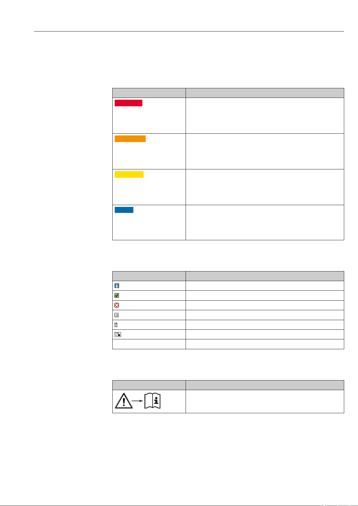
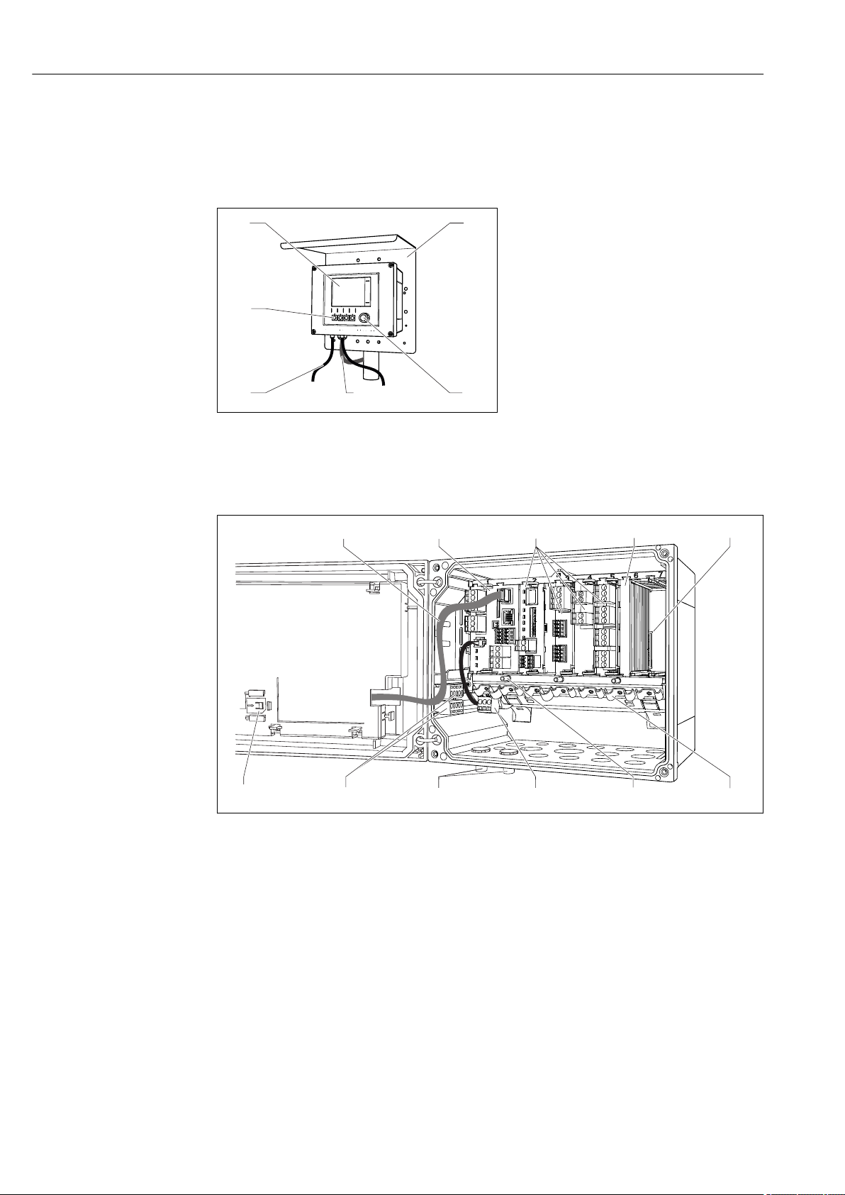
3.1 Housing closed (field device)
1 Display
2 Weather protection cover (optional)
3 Navigator
4 Sensor cable or current output cable
5 Power supply cable
6 Soft keys, assignment depends on menu
A0025813
1 Mounted on a post
3.2 Housing open (field device)
A0039719
2 Example of a four-channel device with an open display cover (without wiring)
1 Display cable 7 Threaded bolt for protective ground connection
2 Basic module 8 Extension power unit with internal cable
3 Extension modules (optional) 9 M12 connectors for sensor connection
(optional)
4 Shock protection, dummy cover and end cover 10 Distributor terminals for user-defined use
5 Extension backplane 11 Storage slot for SD card
6 Cable mounting rail
1)
1) Example: you want to loop the signal from the alarm relay to a siren and a lamp. The terminals on the
alarm relay only accommodate one cable. Route the signal from the alarm relay to a terminal on the
distributor block. The block's terminals are all interconnected. You therefore have 3 additional terminals on
this block from where you can carry the signal forward to the consumer (siren, lamp etc.). The signal can
be multiplied in this way.
10 Endress+Hauser
Page 11
Liquiline CM44P Device description
1 2
3
4
5
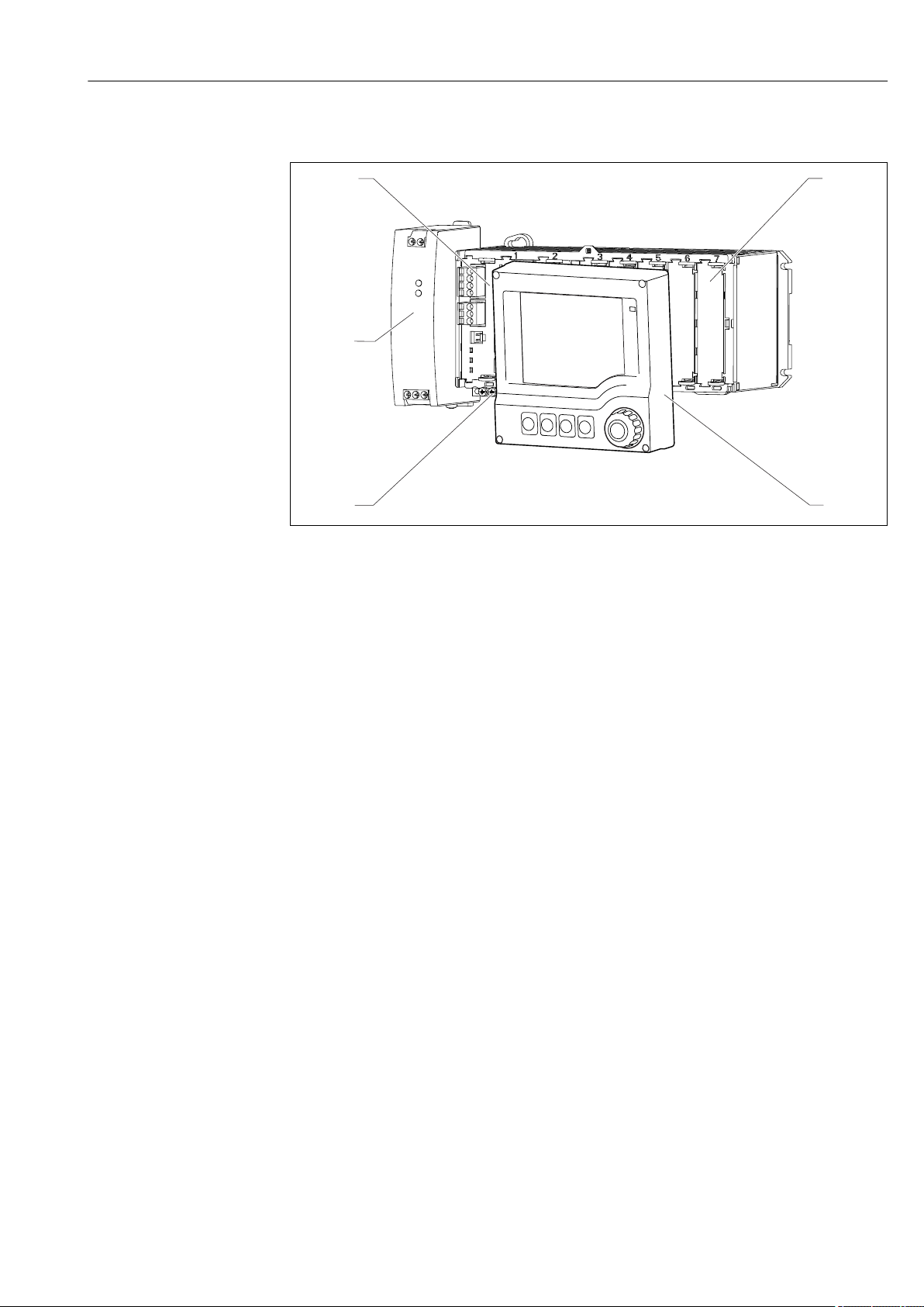
3.3 Overview (cabinet device)
3 Device with optional, external display (excluding cables)
1 Basic module 5 Terminal strip
2 Shock protection, dummy module 6 External power unit
3 External display (optional)
A0039727
Endress+Hauser 11
Page 12
Device description Liquiline CM44P
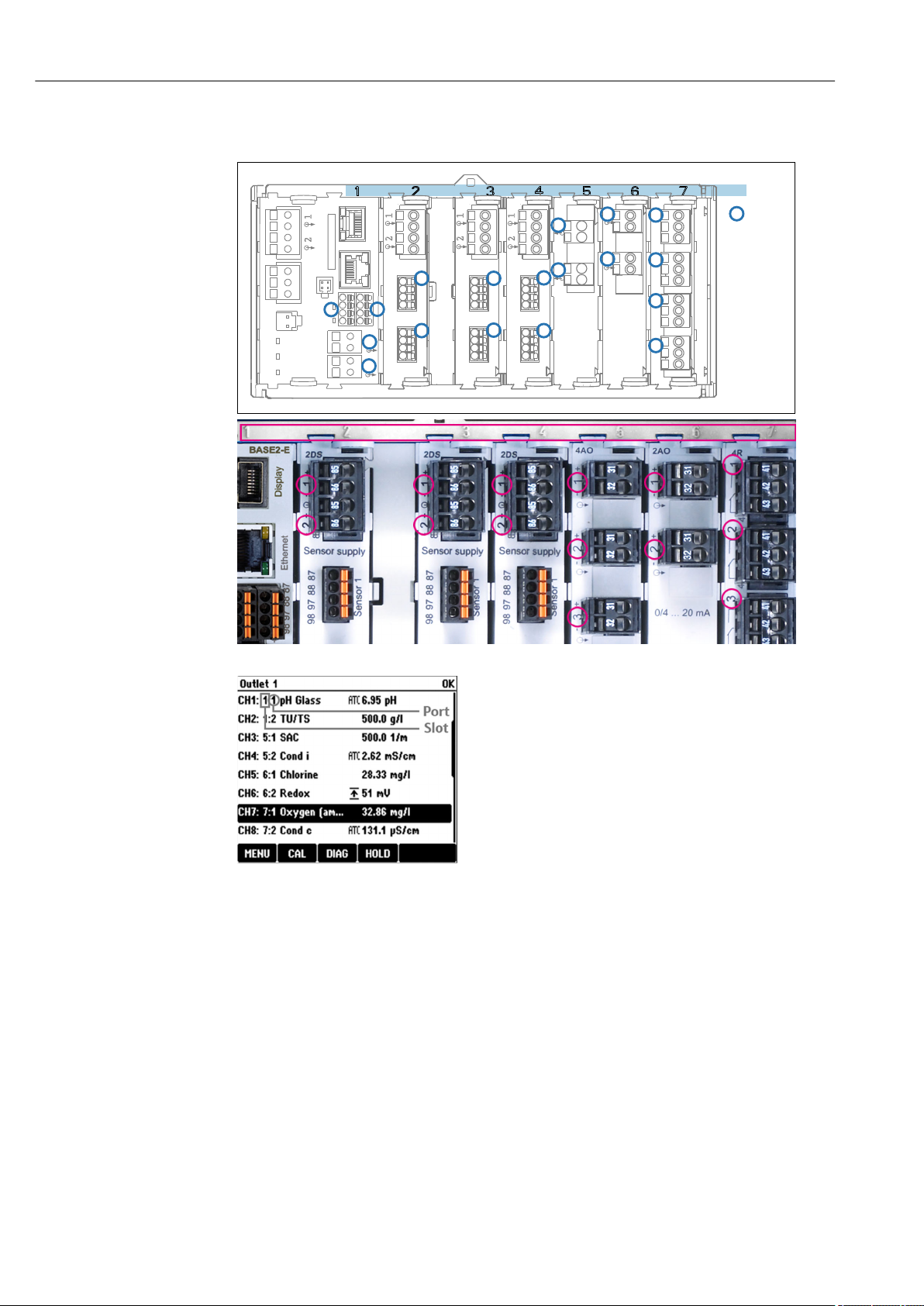
BASE2-E
Slots
1
2
1
2
1
2
1
2
Ports
2DS 2DS 2DS 2AI 2AO 4R
1
2
Sensor 1
Sensor 1
Sensor 1
Sensor 2
Sensor 2
Sensor 2
1
2
1
2
1
2
1
2
3
4
3.4 Slot and port assignment
4 Slot and port assignment of the hardware modules
• Inputs are assigned to measuring channels in the
ascending order of the slots and ports.
Adjacent example:
"CH1: 1:1 pH glass" means:
Channel 1 (CH1) is slot 1 (basic module) : Port 1 (input
1), pH glass sensor
• Outputs and relays are named according to their
function, e.g. "current output", and are displayed in
ascending order with the slot and port numbers
5 Slot and port assignment on the
display
12 Endress+Hauser
Page 13
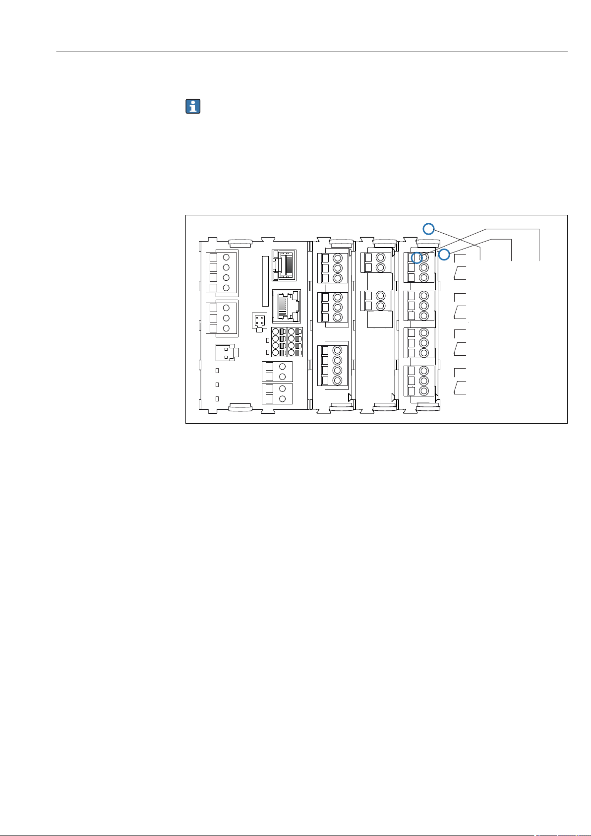
Liquiline CM44P Device description
1 2
3
4
43
42 41
43
42 41
43
42 41
43
42 41
Relay 1
Relay 2
Relay 3
Relay 4
Slot
Slot 4
Port 1
Pin 41
BASE2-E
3.5 Terminal diagram
The unique terminal name is derived from:
Slot no. : Port no. : Terminal
Example, NO contact of a relay
Device with 2 inputs for digital sensors, 4 current outputs and 4 relays
• Base module BASE2-E (contains 2 sensor inputs, 2 current outputs)
• PEM module (1 photometer sensor)
• 2AO module (2 current outputs)
• 4R module (4 relays)
6 Creating a terminal diagram using the example of the NO contact (terminal 41) of a relay
A0039659
Endress+Hauser 13
Page 14

Incoming acceptance and product identification Liquiline CM44P
4 Incoming acceptance and product
identification
4.1 Incoming acceptance
1. Verify that the packaging is undamaged.
Notify the supplier of any damage to the packaging.
Keep the damaged packaging until the issue has been resolved.
2. Verify that the contents are undamaged.
Notify the supplier of any damage to the delivery contents.
Keep the damaged goods until the issue has been resolved.
3. Check that the delivery is complete and nothing is missing.
Compare the shipping documents with your order.
4. Pack the product for storage and transportation in such a way that it is protected
against impact and moisture.
The original packaging offers the best protection.
Make sure to comply with the permitted ambient conditions.
If you have any questions, please contact your supplier or your local Sales Center.
4.2 Product identification
4.2.1 Nameplate
The nameplate provides you with the following information on your device:
• Manufacturer identification
• Order code
• Extended order code
• Serial number
• Ambient and process conditions
• Input and output values
• Activation codes
• Safety information and warnings
Compare the information on the nameplate with the order.
‣
4.2.2 Product identification
Product page
www.endress.com/cm44p
Interpreting the order code
The order code and serial number of your product can be found in the following locations:
• On the nameplate
• In the delivery papers
Obtaining information on the product
1. Go to www.endress.com.
2. Call up the site search (magnifying glass).
3. Enter a valid serial number.
14 Endress+Hauser
Page 15

Liquiline CM44P Incoming acceptance and product identification
4. Search.
The product structure is displayed in a popup window.
5. Click on the product image in the popup window.
A new window (Device Viewer) opens. All of the information relating to your
device is displayed in this window as well as the product documentation.
Manufacturer's address
Endress+Hauser Conducta GmbH+Co. KG
Dieselstraße 24
D-70839 Gerlingen
4.3 Scope of delivery
The scope of delivery comprises:
• 1 multichannel controller in the version ordered
• 1 mounting plate
• 1 wiring label (attached at the factory to the inside of the display cover)
• 1 external display (if selected as an option)
• 1 DIN rail power unit incl. Cable (cabinet device only)
• 1 printed copy of the Operating Instructions for DIN rail power unit (cabinet device only)
• 1 printed copy of the Brief Operating Instructions in the language ordered
If you have any queries:
‣
Please contact your supplier or local sales center.
1)
4.4 Certificates and approvals
4.4.1
The product meets the requirements of the harmonized European standards. As such, it
complies with the legal specifications of the EU directives. The manufacturer confirms
successful testing of the product by affixing to it the mark.
4.4.2 cCSAus
The device has been certified with regard to its electrical safety and for NI Class I Div. 2
cCSAus explosion-proof environments. It meets the requirements in accordance with:
• CLASS 2252 06 - Process Control Equipment
• CLASS 2252 86 - Process Control Equipment - Certified to US Standards
• CLASS 2258 03 - Process Control Equipment - Intrinsically Safe and Non-incendive
Systems - For Hazardous Locations
• CLASS 2258 83 - Process Control Equipment - Intrinsically Safe and Non-incendive
Systems - For Hazardous Locations - Certified to US Standards
• FM3600
• FM3611
• FM3810
• UL50E
• IEC 60529
• CAN/CSA-C22.2 No. 0
• CAN/CSA C22.2 No. 94
• CSA Std. C22.2 No. 213
• CAN/CSA-C22.2 No. 61010-1
mark
1) The external display can be selected as an option in the order structure or ordered as an accessory at a later stage.
Endress+Hauser 15
Page 16

Incoming acceptance and product identification Liquiline CM44P
• CAN/CSA-C22.2 No. 60529
• UL/ANSI/ISA 61010-1
• ANSI - ISA 12 12 01
16 Endress+Hauser
Page 17
Liquiline CM44P Installation
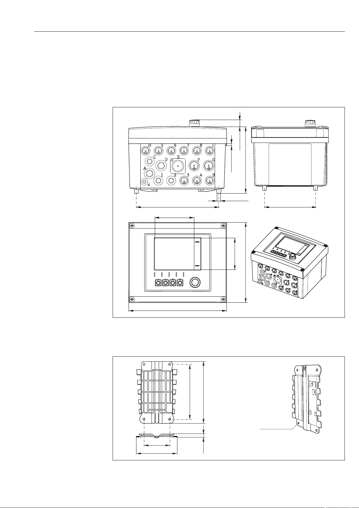
H 5 6 7 8 I
GF
E
D
C
A
1 2 3 4 B
162 (6.38)
14 (0.55)
Ø4 (0.16)
Ø9 (0.35)
199 (7.38) 128 (5.04)
237 (9.33)
194 (7.64)
76 (2.99)
95 (3.74)
80 (3.15)
190 (7.48)
3 (0.12)
4 x 6.5 (0.26)
170 (6.69)
125 (4.92)
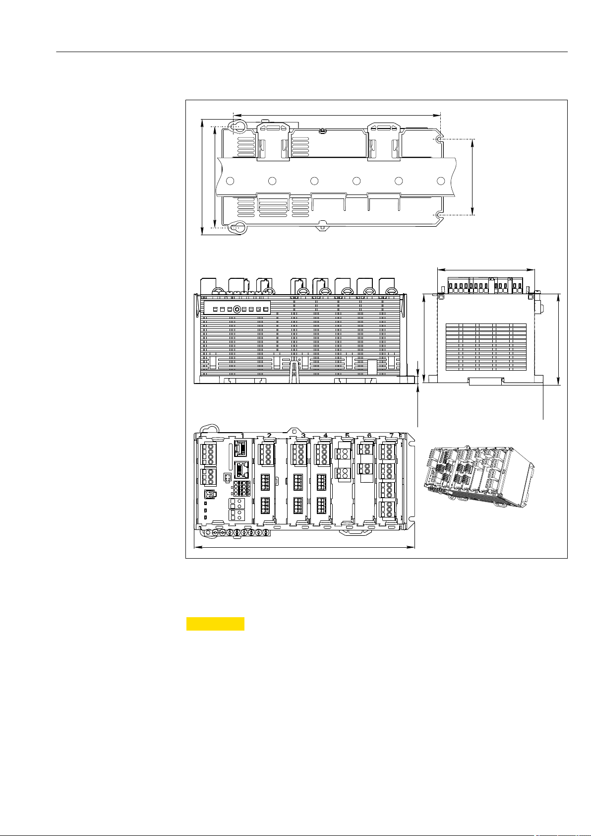
5 Installation
5.1 Installation conditions
5.1.1 Dimensions
Endress+Hauser 17
7 Dimensions of field housing in mm (inch)
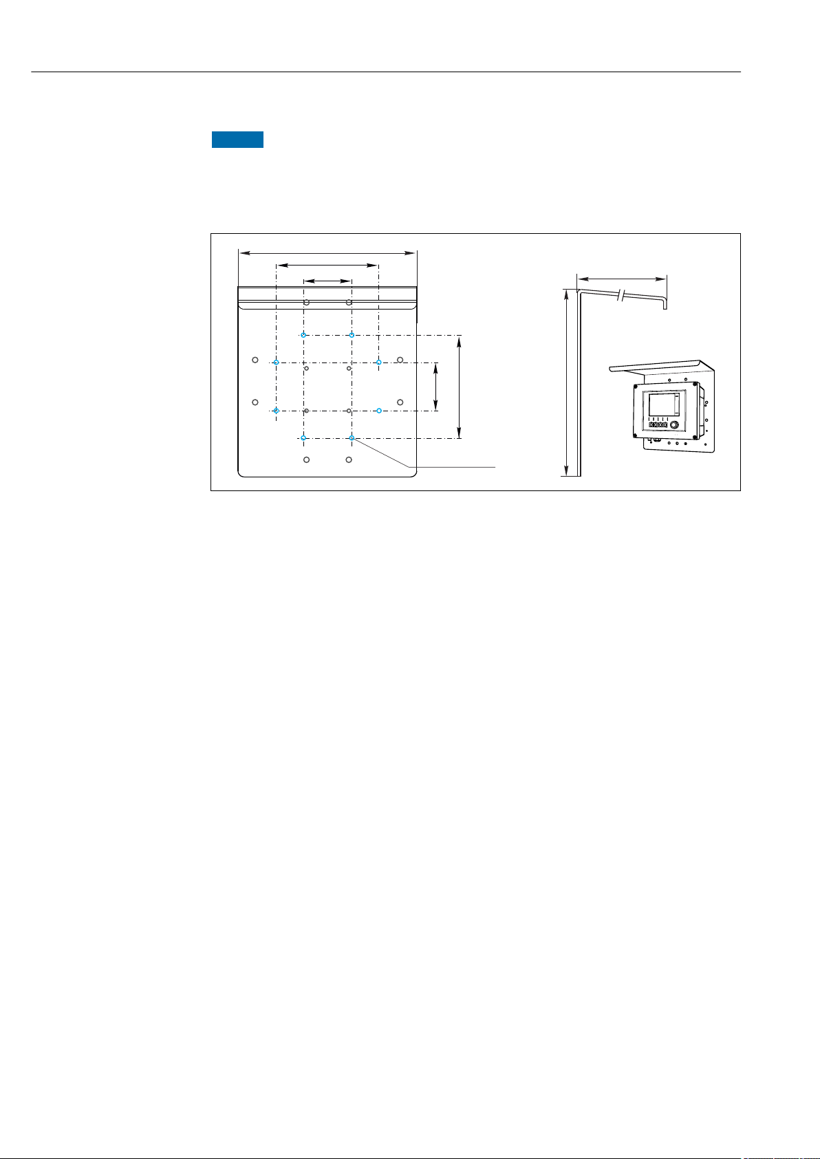
5.1.2 Mounting plate
8 Mounting plate, dimensions in mm (in)
A0012396
A0012426
Page 18
Installation Liquiline CM44P
320 (12.6)
270 (10.6)
300 (11.8)
80 (3.15)
170 (6.69)
170 (6.69)
80 (3.15)
8 x Ø 7 (0.28)
5.1.3 Protective cover
NOTICE
Effect of climatic conditions (rain, snow, direct sunlight etc.)
Impaired operation to complete transmitter failure are possible!
Always use the weather protection cover (accessory) when installing the device
‣
outdoors.
9 Dimensions in mm (in)
A0012428
18 Endress+Hauser
Page 19
Liquiline CM44P Installation
220 (8.66)
97 (3.82)
7.5 (0.30)
100 (3.94)
75 (2.95)
205.5 (8.09)
114 (4.49)
TS 35
TS 35
89 (3.50)
91 (3.58)
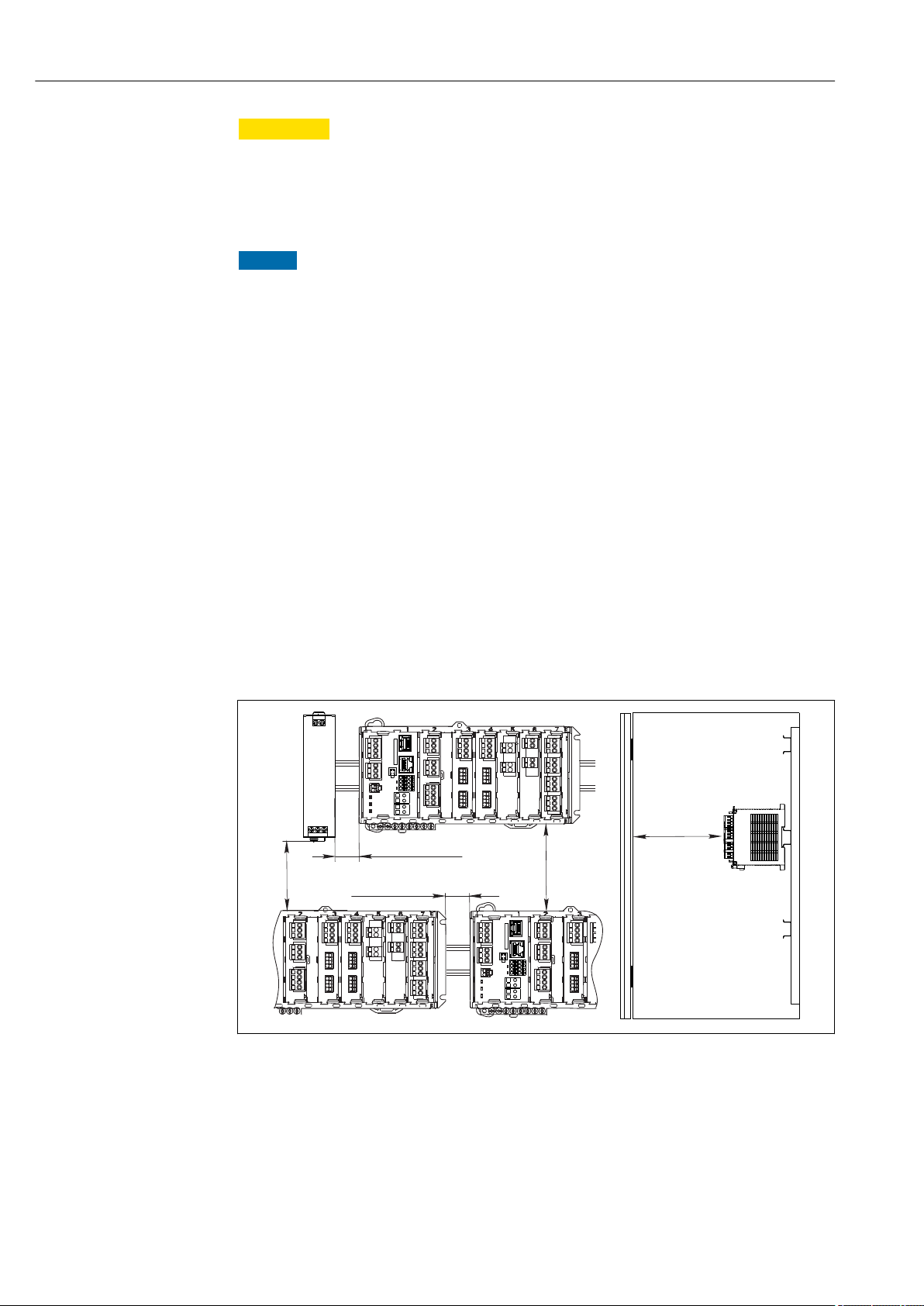
5.1.4 Dimensions (cabinet device)
10 Dimensions in mm (inch)
5.1.5 Mounting on DIN rail as per IEC 60715
CAUTION
L
The power unit can get very hot under full load
Burn hazard!
Avoid touching the power unit during operation.
‣
The minimum distances to other devices must be observed.
‣
After switching off the power unit, allow it to cool down before carrying out any work
‣
on it.
A0039730
Endress+Hauser 19
Page 20
Installation Liquiline CM44P
min. 50 (1.97)
min. 20 (0.79)
min. 50 (1.97)
min. 20 (0.79)
min. 50 (1.97)
CAUTION
L
Impermissible collection of moisture in the device
Puts the safety of the user at risk!
The device has IP20 shock protection. Never allow moisture to collect in the device.
‣
Comply with the specified ambient conditions,e.g. by installing the device in an
‣
appropriate protective enclosure.
NOTICE
Incorrect mounting location in the cabinet, spacing regulations not observed
Possible malfunctions as a result of heat buildup and interference from neighboring
devices!
Do not position the device directly above sources of heat. The temperature specification
‣
must be observed.
The components are designed for convection-based cooling. Avoid heat buildup. Ensure
‣
openings are not covered, e.g. by cables.
Observe the specified distances to other devices.
‣
Physically separate the device from frequency converters and high-voltage devices.
‣
Recommended installation direction: horizontal. The specified ambient conditions, and
‣
particularly the ambient temperatures, only apply for horizontal installation.
Vertical orientation is also possible. However, this requires additional fixing clips at the
‣
place of installation to hold the device in position on the DIN rail.
Recommended installation of power unit: to the left of the device.
‣
The following minimum clearance specifications must be observed:
• Distances at the side in relation to other devices incl. power units and to the wall of the
cabinet:
at least 20 mm (0.79 inch)
• Distance above and below the device and depth distance (to control cabinet door or other
devices installed there):
at least 50 mm (1.97 inch)
11 Minimum clearance in mm (in)
20 Endress+Hauser
A0039736
Page 21
Liquiline CM44P Installation
205.5 (8.09)
100 (3.94)
75 (2.95)
4 x Ø 4.5 (0.18)
4 x min. Ø 8 (0.31)
min. Ø 15 (0.59)
140 (5.51)
105 (4.13)
105 (4.13)
140 (5.51)
a
b
b
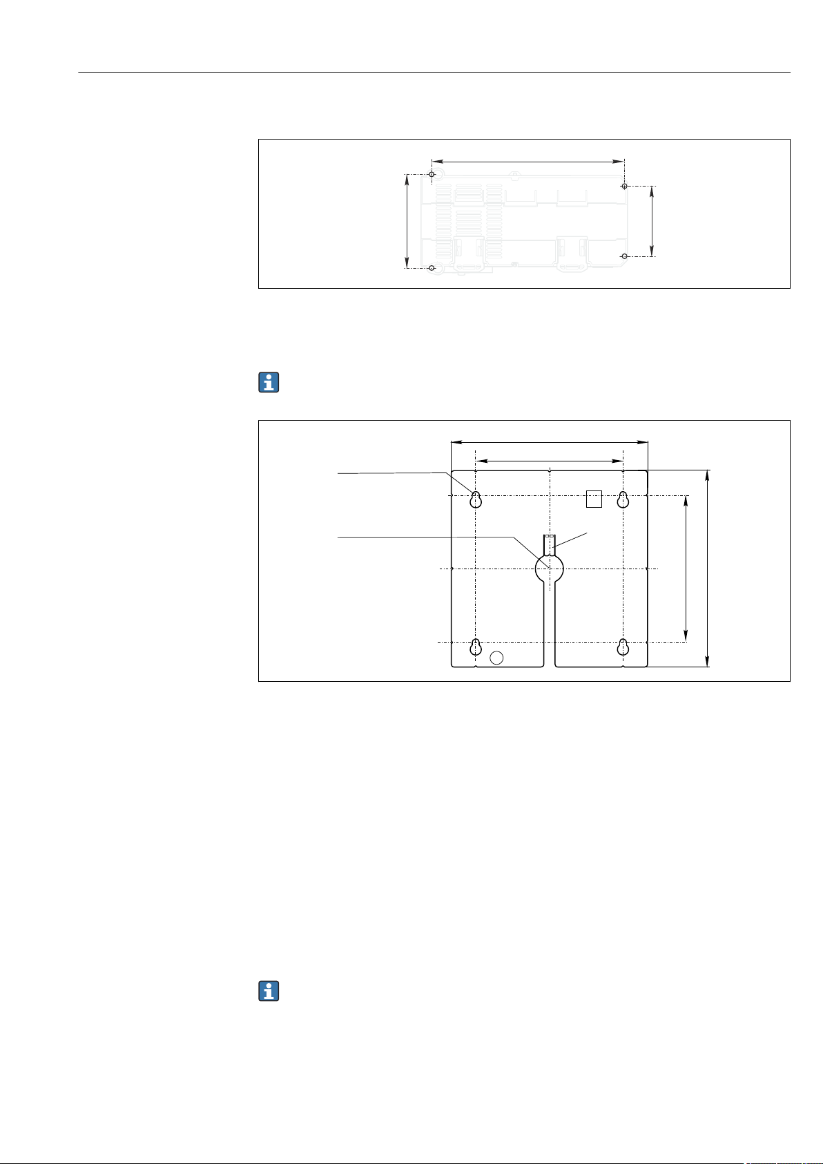
5.1.6 Wall mounting
A0027859
12 Drilling pattern for wall mounting in mm (in)
5.1.7 Mounting the external display
The mounting plate also serves as the drilling template. The marks on the side help
you mark the position of the drill holes.
13 Mounting plate of external display, dimensions in mm (in)
a Retaining tab
b Production-related recesses, no function for the user
5.1.8 Cable length for optional display
Length of display cable provided (cabinet device only):
3 m (10 ft)
Maximum permitted length of a display cable (cabinet device only):
5 m (16.5 ft)
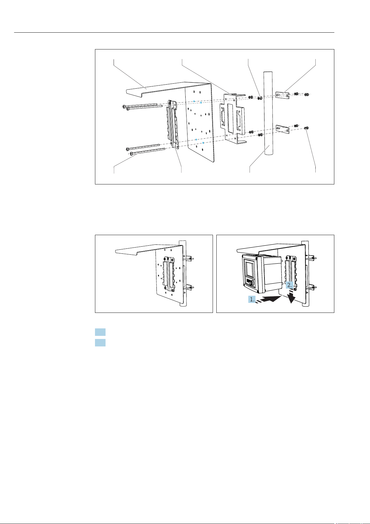
5.2 Mounting the measuring device (field device)
5.2.1 Post mounting
You require the post mounting kit (optional) to mount the unit on a pipe, post or
railing (square or circular, clamping range 20 to 61 mm (0.79 to 2.40")).
A0025371
Endress+Hauser 21
Page 22
Installation Liquiline CM44P
1
2
3
4
56
7
8
A0033044
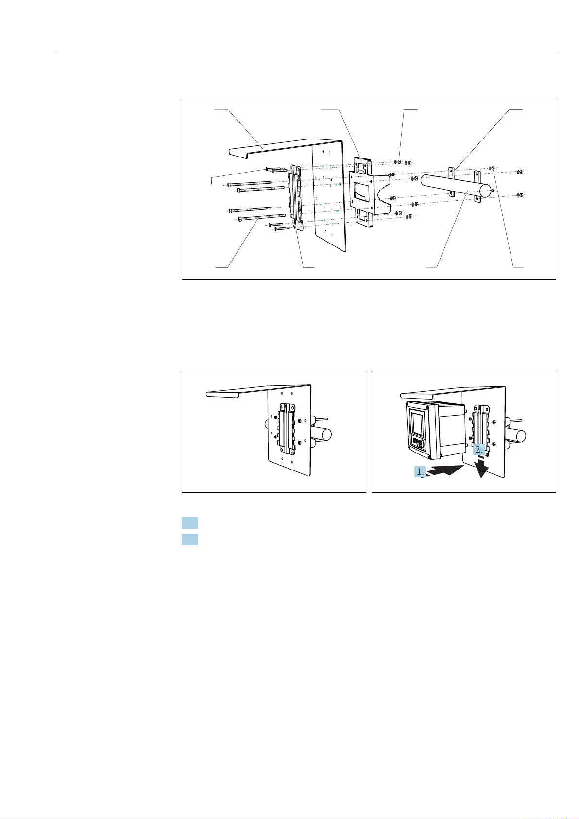
14 Post mounting
1 Weather protection cover (optional) 5 Spring washers and nuts (post mounting kit)
2 Post mounting plate (post mounting kit) 6 Pipe or railing (circular/square)
3 Spring washers and nuts (post mounting kit) 7 Mounting plate
4 Pipe clamps (post mounting kit) 8 Threaded rods (post mounting kit)
15 Post mounting
A0033045
16 Attach the device and click it into place
A0025885
1. Place the device on the mounting plate.
2. Slide the device downwards in the guide on the mounting rail until it clicks into place.
22 Endress+Hauser
Page 23
Liquiline CM44P Installation
1 2
3
4
56
7
8
9
5.2.2 Rail mounting
A0012668
17 Rail mounting
1 Weather protection cover (optional) 6 Pipe or railing (circular/square)
2 Post mounting plate (post mounting kit) 7 Mounting plate
3 Spring washers and nuts (post mounting kit) 8 Threaded rods (post mounting kit)
4 Pipe clamps (post mounting kit) 9 Screws (post mounting kit)
5 Spring washers and nuts (post mounting kit)
18 Rail mounting
A0025886
19 Attach the device and click it into place
A0027803
1. Place the device on the mounting plate.
2. Slide the device downwards in the guide on the mounting rail until it clicks into place.
Endress+Hauser 23
Page 24
Installation Liquiline CM44P
≥ 340 (13.4)
≥
150 (5.91)
1
3
4
2
5.2.3 Wall mounting
A0027798
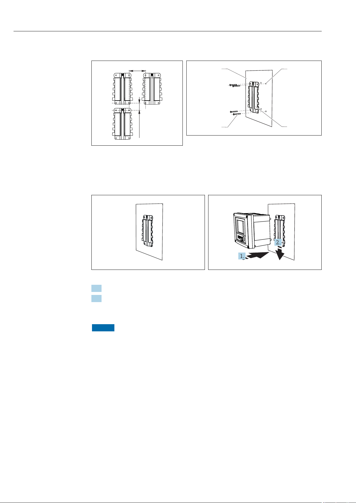
21 Wall mounting
A0012686
20 Installation clearance in mm (in)
1)
The size of the drill holes depends on the wall plugs used. The wall plugs and screws must be provided by the
customer.
1 Wall
2
4 drill holes
3 Mounting plate
4 Screws Ø 6 mm (not part of scope of supply)
1)
22 Wall mounting
A0027799
23 Attach the device and click it into place
A0027797
1. Place the device on the mounting plate.
2. Slide the device downwards in the guide on the mounting rail until it clicks into place.
5.2.4 Disassembly (for conversion, cleaning etc.)
NOTICE
The device can be damaged if dropped
When pushing the housing out of the holder, secure the housing to prevent it from
‣
falling. If possible, ask a second person to help you.
24 Endress+Hauser
Page 25
Liquiline CM44P Installation
A0025890
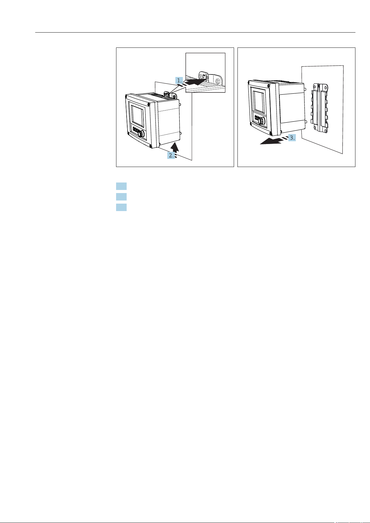
24 Disassembling
25 Disassembling
1. Hold down the latch.
2. Push up the device to remove it from the holder.
3. Remove the device towards the front.
A0025891
Endress+Hauser 25
Page 26
Installation Liquiline CM44P
a
b
5.3 Mounting the measuring device (cabinet device)
5.3.1 DIN rail mounting
The mounting procedure is the same for all Liquiline devices. The example shows a
CM448R.
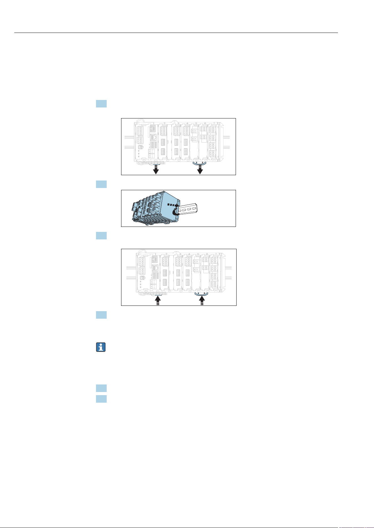
1. In the order configuration, the securing clips are "tightened" to secure the DIN rail.
Release the securing clips by pulling them downwards.
2. Attach the device from the top to the DIN rail (a) and secure it by pressing down (b).
3. Slide the securing clips upwards until they click, thereby securing the device to the
DIN rail.
4. Mount the external power unit in the same way.
5.3.2 Wall mounting
Mounting material (screws, dowels) are not included in the scope of delivery and must
be provided by the customer.
The external power unit can be mounted on a DIN rail only.
Use the back of the housing to mark the mounting holes.
1. Drill the corresponding holes and insert wall plugs if necessary.
2. Screw the housing onto the wall.
26 Endress+Hauser
Page 27
Liquiline CM44P Installation
.
.
.
. .
.
.
.
..
.
.
.
.
.
. .
.
.
.
..
.
.
4 x Ø 8 (0.31)
Ø 20 (0.79)
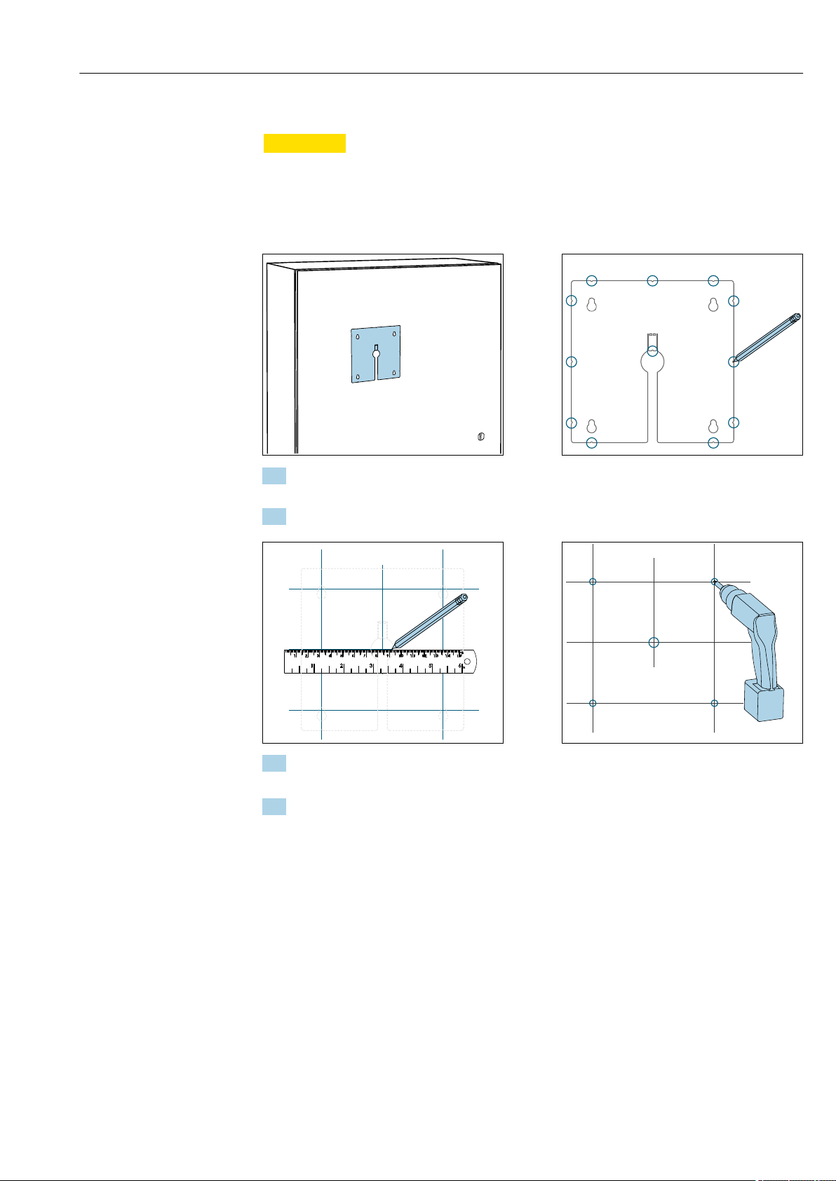
5.3.3 Mounting the optional external display
CAUTION
L
Sharp-edged, non-deburred drill holes
Risk of injury, display cable may get damaged!
In particular, deburr the central drill hole for the display cable.
‣
Mounting the display on the door of the cabinet
1. Hold the mounting plate from the outside against the door of the control cabinet.
Choose the point at which you wish to install the display.
2. Make all the markings.
3. Draw lines to interconnect all the marks.
This will indicate the position of the five drill holes needed.
4. Drill the holes (→ 13, 21).
Endress+Hauser 27
Page 28
Installation Liquiline CM44P
a
b
c
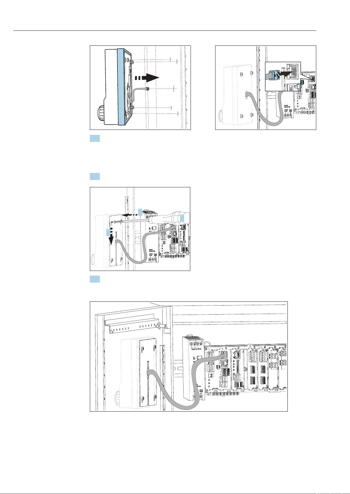
5. Pull the display cable through the hole in the middle, and place the display from the
outside through the four holes drilled for this purpose, ensuring that the torx screws
have been unscrewed to the last half turn but are still in place. Ensure that the rubber
frame (seal, highlighted blue) does not become damaged and is properly positioned
on the surface of the door.
6. Connect the display cable to the RJ-45 socket in the base module.
7. Place the mounting plate on the inside over the screws (a), slide it down (b) and
tighten the screws (c).
The display is now mounted and ready to use.
26 Mounted display
28 Endress+Hauser
Page 29

Liquiline CM44P Installation
NOTICE
Incorrect installation
Damage, e.g. to the cable, or malfunctions are possible!
Lay cables in such a way that they do not get squashed e.g. when closing the cabinet
‣
door.
Plug the display cable only into the RJ45 socket in the base module. Otherwise, the
‣
display will not function.
5.4 Post-installation check
1. After installation, check the transmitter for damage.
2. Check whether the transmitter is protected against precipitation and direct sunlight
(e.g. by the weather protection cover).
3. After mounting, check all devices (controller, power unit, display) for damage.
4. Verify that the specified installation clearances have been observed.
5. Verify that all securing clips have been snapped into place and that the components
are securely positioned on the DIN rail.
6. Ensure that the temperature limits are observed at the mounting location.
Endress+Hauser 29
Page 30
Electrical connection Liquiline CM44P
1
3
2
USB
31
32
250 ... 500 Ω
FXA291
Master class 1
(PLC, DCS)
T T
Ethernet
PROFIBUS DP
(RS485)
Master class 2 (FieldCare, PDM)
6 Electrical connection
6.1 Connection conditions
6.1.1 Via HART (e.g. via HART modem and FieldCare)
27 HART using modem
1 Device module Base2-L, -H or -E: current output 1 with HART
2
HART modem for connection to PC, e.g. Commubox FXA191 (RS232) or FXA195 1) (USB)
3 HART handheld terminal
1)
Switch position "on" (substitutes the resistor)
6.1.2 Via PROFIBUS DP
A0039620
28 PROFIBUS DP
T Terminating resistor
30 Endress+Hauser
A0039617
Page 31

Liquiline CM44P Electrical connection
FXA291
Ethernet
Modbus Master / Gateway
T T
Modbus RS485
(RTU, ASCII)
FieldCare/
Webbrowser
FXA291
Ethernet
Ethernet client
6.1.3 Via Modbus RS485
A0039615
29 Modbus RS485
T Terminating resistor
6.1.4 Via Ethernet: web server/Modbus TCP/PROFINET/ EtherNet/IP
A0039616
30 Modbus TCP or EtherNet/IP or PROFINET
6.2 Connecting the measuring device
WARNING
L
Device is live!
Incorrect connection may result in injury or death!
The electrical connection may be performed only by an electrical technician.
‣
The electrical technician must have read and understood these Operating Instructions
‣
and must follow the instructions contained therein.
Prior to commencing connection work, ensure that no voltage is present on any cable.
‣
Endress+Hauser 31
Page 32

Electrical connection Liquiline CM44P
1.
2.
3.
4.
≤180°
NOTICE
The device does not have a power switch!
Provide a protected circuit breaker in the vicinity of the device at the place of
‣
installation.
The circuit breaker must be a switch or power switch, and must be labeled as the circuit
‣
breaker for the device.
At the supply point, the power supply must be isolated from dangerous live cables by
‣
double or reinforced insulation in the case of devices with a 24 V supply voltage.
6.2.1 Opening the housing
NOTICE
Pointed or sharp tools
If unsuitable tools are used, they can scratch the housing or damage the seal, and thus
have a negative impact on the leak-tightness of the housing!
Do not use pointed or sharp objects,e.g. knives, to open the housing.
‣
Only use a suitable Phillips screwdriver.
‣
31 Releasing housing screws in a diagonally
opposite sequence with Phillips screwdriver
32 Opening display cover, max. opening angle
180˚ (depends on installation position)
1. Release the housing screws on a step-by-step basis. Start with any screw of your
choice. Then release the screw diagonally opposite this screw etc.
2. To close the housing: tighten the screws in a similar step-by-step, diagonally opposite
sequence.
32 Endress+Hauser
Page 33

Liquiline CM44P Electrical connection
1 32 4
1
2
3
4
6.2.2 Cable mounting rail
A0025171
33 Cable mounting rail and associated function (field device)
A0025366
34 Mounting rail for functional ground connections (cabinet device)
1 Cable mounting rail 3 Additional threaded bolts for ground connections
2 Threaded bolt (protective ground connection,
central grounding point)
4 Cable clamps (fixing and grounding the sensor
cables)
6.2.3 Connecting the cable shield
If possible, only use terminated original cables. The sensor, fieldbus and Ethernet
cables must be shielded cables.
Cable sample (does not necessarily correspond to the original cable supplied)
35 Terminated cable
1 Outer shield (exposed)
2 Cable cores with ferrules
3 Cable sheath (insulation)
1) Please note the instructions in the "Ensuring the degree of protection" section (→ 48)
1. Release a suitable cable gland on the bottom of the housing and remove the dummy
plug.
2. Making sure the gland is facing the right direction, thread the gland onto the cable
end and pull the cable through the entry and into the housing.
3. Route the cable in the housing in such a way that the exposed cable shield fits into
one of the cable clamps and the cable cores can be easily routed as far as the
connection plug on the electronics module.
4. Screw the cable clamp on.
5. Clamp the cable into place.
6. Then tighten the screw of the cable clamp again.
7. Connect cable cores as per the wiring diagram.
Endress+Hauser 33
36 Insert the cable
4 Grounding clip
37 Tighten screw (2 Nm)
The cable shield is grounded using
the grounding clamp.
1)
Page 34

Electrical connection Liquiline CM44P
8. Tighten the cable gland from outside.
6.2.4 Cable terminals
Plug-in terminals for Memosens and PROFIBUS/RS485 connections
Insert the cable until the limit
Press the screwdriver against
‣
the clip (opens the terminal).
After connection, make sure that every cable end is securely in place. Terminated
cable ends, in particular, tend to come loose easily if they have not been correctly
inserted as far as the limit stop.
‣
stop.
Remove the screwdriver (closes
‣
the terminal).
All other plug-in terminals
Press the screwdriver against
‣
the clip (opens the terminal).
Insert the cable until the limit
‣
stop.
Remove the screwdriver (closes
‣
the terminal).
34 Endress+Hauser
Page 35

Liquiline CM44P Electrical connection
L+ N- PE
A
B
85
85
86
86
SD
Display
Sensor supply
+
+
–
Service
PK
GY
PK
GY
1
2
–
+
–
A
B
41
43
42
Alarm
31
31
32
32
0/4 ... 20 mA
+
+
–
–
HART
+
–
A
B
Sensor 2
Ethernet
87
88
97
98
87
88
97
98
BN
WH
GN
YE
BN
WH
GN
YE
Sensor 1
1
2
L/+
N/–
*
Power
L/+
N/–
PE
Power
(internal)
B
L N
+ RD
- BK
*
85
85
86
86
SD
Display
Sensor supply
+
+
–
Service
PK
GY
PK
GY
1
2
–
+
–
A
B
41
43
42
Alarm
31
31
32
32
0/4 ... 20 mA
+
+
–
–
HART
+
–
A
B
Sensor 2
Ethernet
87
88
97
98
87
88
97
98
BN
WH
GN
YE
BN
WH
GN
YE
Sensor 1
1
2
L/+
N/–
*
Power
L/+
N/–
PE
Power
(internal)
B
6.2.5 Connecting the supply voltage
A0039626
38 Power supply connection on the BASE2-E
(field device)
A Internal power supply cable
B Extension power unit
40 Connecting power supply with BASE2-E
(cabinet device)
* Assignment depending on power unit, make sure
to connect correctly
The two device versions may only be operated with the power unit supplied and the
power unit cable. Also pay attention to the information in the operating manual
supplied for the power unit.
39 Overall wiring diagram for BASE2-E and
extension power unit (B)
A0039668
41 Overall wiring diagram for BASE2-E and
external power unit (B)
Endress+Hauser 35
A0039624
A0039624
Page 36

Electrical connection Liquiline CM44P
Connecting the supply voltage
1. Route the power supply cable into the housing through the suitable cable entry.
2. Step 2 applies only to the 100 to 230 V AC power unit.
Connect the protective ground of the power unit to the threaded bolt specially
provided on the cable mounting rail.
3. Protective ground or grounding provided by customer (absolutely essential for 24 V
power unit, additionally recommended for 100 to 230 V AC power unit): Provide
a ground cable (min. 0.75 mm2 (corresponding to 18 AWG))1! Guide the ground
cable also through the cable entry and connect it to the threaded bolt on the cable
mounting rail.
4. Connect the cable cores L and N (100 to 230 V AC) or + and ‐ (24 V DC) to the plugin terminals on the power unit in accordance with the wiring diagram.
NOTICE
Protective ground/ground cable with end sleeve or open cable lug
The cable can become loose. Loss of the protective function!
To connect the protective ground or ground cable to the threaded bolt, only use a cable
‣
with a closed cable lug as per DIN 46211, 46225, form A.
Never connect the protective ground or ground cable to the threaded bolt with an end
‣
sleeve or an open cable lug!
NOTICE
Incorrect connection and cable run not separate
Interference on signal or display cable, incorrect measured values or failure of display may
occur!
Do not connect the cable shield of the display cable to PE (terminal strip of device)!
‣
Run the signal/display cable in the control cabinet separately from live (current-
‣
carrying) cables.
6.3 Connecting the sensors
6.3.1 Sensor types
Photometer sensors
Sensor types Sensor cable Sensors
Analog photometer sensors without additional internal
power supply
CUK80 • OUSAF12
• OUSAF21
• OUSAF22
• OUSAF44
• OUSAF46
• OUSTF10
• OUSBT66
Fixed cable OUSAF11
36 Endress+Hauser
Page 37

Liquiline CM44P Electrical connection
GN/YE
Sensors with Memosens protocol
Sensor types Sensor cable Sensors
Digital sensors without
additional internal power
supply
Digital sensors with
additional internal power
supply
With plug-in
connection and
inductive signal
transmission
Fixed cable Conductivity sensors with inductive measurement of
Fixed cable • Turbidity sensors
• pH sensors
• ORP sensors
• Combined sensors
• Oxygen sensors (amperometric and optical)
• Conductivity sensors with conductive measurement
of conductivity
• Chlorine sensors (disinfection)
conductivity
• Sensors for interface measurement
• Sensors for measuring the spectral absorption
coefficient (SAC)
• Nitrate sensors
• Optical oxygen sensors
• Ion-sensitive sensors
The following rule applies if connecting CUS71D sensors:
• The maximum number of Memosens inputs is limited to two.
• Any combination of CUS71D or other sensors is possible.
6.3.2 Connecting the functional ground (cabinet device)
You must always connect the terminal strip with PE from the central node in the cabinet.
Use the conductor with cable clamp that is included with the Memosens cable to connect
the functional earth to the terminal strip of the device.
42 Functional earth connection
You must only ever connect one functional earth to each screw in the terminal strip.
Otherwise, shielding is not guaranteed.
6.3.3 Connecting the sensors
Types of connection
• Direct connection of the sensor cable to the terminal connector of the sensor module
PEM and the Memosens module 2DS or of the base module-E (→ 43 ff.)(Memosens
sensors only)
• Optional for Memosens sensors: Sensor cable plug connected to the M12 sensor socket
on the underside of the device (field device)
With this type of connection, the device is already wired at the factory (→ 47).
Endress+Hauser 37
Page 38

Electrical connection Liquiline CM44P
98 97 88 87
86 85 86 85
BN
WH
GN
YE
Sensor
98 97 88 87
86 85 86 85
GN
YE
Sensor
PK
GY
85 86
85
2DS
1
2
86
97 88 8798
97 88 8798
Sensor 1
Sensor 2
PK
GY
GN
YE
BN
WH
GN
YE
Sensor
Sensor
1. Sensor cable connected directly
Connect the sensor cable to the terminal connector of the sensor module PEM 2DS or
of the module Base2-E.
2. When connecting via M12 connector (Memosens sensors only)
Connect the sensor connector to an M12 sensor socket which has been previously
installed or is supplied on delivery.
Sensor cable connected directly
A0039629
43 Memosens sensors without additional supply
voltage
A0033206
45 Memosens sensors with and without
44 Memosens sensors with additional supply
voltage
46 PEM module
A0039622
A0028599
additional supply voltage at sensor module 2DS
38 Endress+Hauser
Page 39

Liquiline CM44P Electrical connection
Connecting photometer sensors to PEM module
Sensor Cable color PEM terminal Assignment
OUSAF11
OUSAF12
OUSAF21
OUSAF22
OUSTF10
OUSAF44
OUSAF46
2 PEM modules
necessary
YE (thick) P+ Lamp voltage +
YE (thin) S+ Recording lamp voltage +
BK (thin) S- Recording lamp voltage -
BK (thick) P- Lamp voltage -
RD A (1) Sensor +
1)
/ WH
2)
C(1) Sensor -
BK
GY SH (1) Shield
YE (thick) P+ Lamp voltage +
YE (thin) S+ Recording lamp voltage +
BK (thin) S- Recording lamp voltage -
BK (thick) P- Lamp voltage -
RD A (1) Measuring detector sensor +
BK C(1) Measuring detector sensor -
GY SH (1) Measuring detector screening
WH A (2) Sensor reference +
GN C(2) Sensor reference -
GY SH (2) Reference screening
PEM module 1
YE (thick) P+ Lamp voltage +
YE (thin) S+ Recording lamp voltage +
BK (thin) S- Recording lamp voltage -
BK (thick) P- Lamp voltage -
RD A (1) Measuring detector sensor +
BK C(1) Measuring detector sensor -
GY SH (1) Measuring detector screening
WH (lamp) A (2) Sensor reference +
GN (lamp) C(2) Sensor reference -
GY (lamp) SH (2) Reference screening
PEM module 2
WH A (1) Measuring detector sensor +
GN C(1) Measuring detector sensor -
GY SH (1) Measuring detector screening
RD (lamp) A (2) Sensor reference +
BK (lamp) C(2) Sensor reference -
GY (lamp) SH (2) Reference screening
Endress+Hauser 39
Page 40

Electrical connection Liquiline CM44P
85 86
85
1
2
86
97 88 8798
Sensor 1
PK
GY
GN
YE
BN
WH
1
6
4
1
NC
2
3
5
7
4
6
2
NC
1
7
5
3
Sensor Cable color PEM terminal Assignment
OUSBT66 BN P+ Lamp voltage +
BN S+ Recording lamp voltage +
BK P- Lamp voltage -
BK S- Recording lamp voltage -
RD A (1) Sensor +
OG C(1) Sensor -
TP SH (1) Shield
1) OUSAF12
2) OUSAF11
Memosens connection via M12 plug-in connection (field device only)
Device versions with a pre-installed
M12 socket are ready-wired upon
delivery.
Version without a pre-installed M12
socket
1. Insert an M12 socket
(accessory) into a suitable
opening in the base of the
housing.
2. Connect the cable to a
Memosens terminal as per the
wiring diagram.
Connecting the sensor
Plug the connector of the sensor
‣
A0018019
47 M12 plug-in connection (e.g.
at sensor module)
1 Sensor cable with M12
connector
A0018021
48 M12 assignment Top:
socket Bottom: connector
(top view in each case)
1 PK (24 V)
2 GY (Ground 24 V)
3 BN (3 V)
4 WH (Ground 3 V)
5 GN (Memosens)
6 YE (Memosens)
7,NCNot connected
cable (→ 47item 1) directly into
the M12 socket.
Please note the following:
• The internal device wiring is always
the same regardless of what kind of
sensor you connect to the M12
socket (plug&play).
• The signal or power supply cables
are assigned in the sensor head in
such a way that the PK and GY
power supply cables are either used
(e.g. optical sensors) or not (e.g. pH
or ORP sensors).
6.4 Connecting additional inputs, outputs or relays
WARNING
L
40 Endress+Hauser
Module not covered
No shock protection. Danger of electric shock!
Change or extend the hardware: always fill the slots from left to right. Do not leave any
‣
gaps.
If all of the slots are not occupied: always insert a dummy cover or end cover in the slot
‣
to the right of the last module(→ 2, 10). This ensures that the unit is shockprotected.
Always ensure shock protection is guaranteed particularly in the case of relay modules
‣
(2R, 4R, AOR).
The terminal strip (cabinet unit) is used to connect the cable shields.
Page 41

Liquiline CM44P Electrical connection
47
47
48
48
+
+
–
1
2
–
1
2
1
2
+
–
–
+
+
–
+
–
45
46
45
46
91
92
91
92
2324
2324
23
23
24
24
0/4 ... 20 mA
+
+
–
1
2
–
If additional shields are required, connect them with PE centrally in the control cabinet
‣
via terminal blocks supplied by the customer.
6.4.1 Digital inputs and outputs
DIO module
49 Module
50 Wiring
diagram
6.4.2 Current inputs
Module 2AI
Endress+Hauser 41
51 Module
52 Wiring
diagram
Page 42

Electrical connection Liquiline CM44P
31
31
32
32
0/4 ... 20 mA
+
+
–
1
2
–
31
31
32
32
0/4 ... 20 mA
+
+
–
1
2
–
31
31
32
32
0/4 ... 20 mA
+
+
–
3
4
–
41
43
42
Relay 1
41
43
42
Relay 2
41
43
42
Relay 3
41
43
42
Relay 4
41
43
42
Relay 1
41
43
42
Relay 2
6.4.3 Current outputs
2AO 4AO
53 Module
54 Wiring
diagram
55 Module
6.4.4 Relay
Module 2R Module 4R
56 Wiring
diagram
57 Module
42 Endress+Hauser
58 Wiring
diagram
59 Module
60 Wiring
diagram
Page 43

Liquiline CM44P Electrical connection
PE L1 N PE
T2.0A
230 V AC / 50 Hz
1
41
43
42
Liquiline/Sampler/
Analyzer:
AOR/2R/4R
41
43
42
Relay 1
41
43
42
Relay 2
1
2
1
2
NL PE
CM44x/CM44xR/
CM44P
CYR10
1
2
3
4
5
Example: Connecting the cleaning unit 71072583 for CAS40D
NOTICE
Power consumption too high for the Liquiline alarm relay!
Can cause irreparable damage to the base module
Connect the cleaning unit only to terminals of an additional module (AOR, 2R or 4R),
‣
not to the alarm relay of the base module.
Endress+Hauser 43
61 Connecting the cleaning unit for CAS40D
Example: Connecting the Chemoclean CYR10 injector cleaning unit
62 Connecting the CYR10 injector cleaning unit
1 External power supply
2 Cleaner to spray head
3 Container with cleaner
4 Motive water 2 to 12 bar (30 to 180 psi)
5 Backflow valve (to be provided by the customer)
A0028597
A0028598
Page 44

Electrical connection Liquiline CM44P
Ethernet
81
82
DIP switch
on
1
2
4
8
16
32
64
128/SW
Service
T
COM
SF
BF
PWR
DGND
VP
96'
95'
99'
Termination
DP/
RS485
96
95
99
6.5 Connecting PROFIBUS DP or Modbus RS 485
6.5.1 Module 485
63 Module
64 Wiring
diagram
Terminal PROFIBUS DP Modbus RS485
95 A B
96 B A
99 Not connected C
82 DGND DGND
81 VP VP
LEDs on front of module
LED Identifier Color Description
RJ45 LNK/ACT GN RJ45 is disabled. Ethernet communication is via the BASE2 module
RJ45 10/100 YE
PWR Power GN Supply voltage is applied and module is initialized
BF Bus failure RD Bus failure
SF System failure RD Device error
COM Communication YE Modbus message sent or received
T Bus termination YE • Off = No termination
• On = Termination is used
DIP switches on front of module
44 Endress+Hauser
DIP Factory setting Assignment
1-128 ON Bus address (→ "Commissioning/communication")
OFF Write protection: "ON" = configuration not possible via the bus, only via local
operation
Service OFF The switch has no function
Page 45

Liquiline CM44P Electrical connection
RD
GN
P0V
P5V
82
81
J1
P2
P1
96
95
99
P2
J1
1
2
3
4
5
1
2
3
4
5
P1
1
2
3
4
5
1 2
34
5
2 1
43
5
RD
GN
P0V
P5V
82
81
J1
P2
P1
96
95
99
P2
J1
1
2
3
4
5
1
2
3
4
5
P1
1
2
3
4
5
1 2
34
5
2 1
43
5
6.5.2 Connection via M12 connector (field device only)
PROFIBUS DP
M12 Y-section Wiring in M12 Y section Pin assignment in connector and
socket
67 Connector (left) and socket
(right)
1 P5V, 5 V power supply for
external terminating resistor
2 A
3 P0V, reference potential for
P5V
4 B
5 n.c., not connected
* Shielding
65 M12 connection
66 Wiring
When using the M12 Y-section, the maximum data transfer rate is limited to
1.5 MBit/s. For direct wiring, the maximum data transfer rate is 12 MBit/s.
Modbus RS485
M12 Y-section Wiring in M12 Y section Pin assignment in connector and
socket
70 Connector (left) and socket
(right)
1 P5V, 5 V power supply for
external terminating resistor
2 A
3 P0V, reference potential for
P5V
4 B
5 n.c., not connected
* Shielding
68 M12 connection
Endress+Hauser 45
69 Wiring
Page 46

Electrical connection Liquiline CM44P
3
4
1
2
4
3
2
1
Ethernet, web server, PROFINET
Internal connection Pin assignment in connector and socket
72 Connector (left) and socket (right)
1 Tx+
2 Rx+
3 Tx4 Rx-
Shielding (thread)
71 Ethernet socket
46 Endress+Hauser
Page 47

Liquiline CM44P Electrical connection
"ON"
"OFF"
390 W
220 W
390 W
VP
DGND
B/B' A/A'
6.5.3 Bus termination
There are 2 ways to terminate the bus:
1. Internal termination (via DIP switch on module board)
73 DIP switch for internal termination
Using a suitable tool such as a tweezer, move all four DIP switches to the "ON" position.
‣
The internal termination is used.
74 Structure of internal termination
2. External termination
Leave the DIP switches on the module board in the "OFF" position (factory setting).
Connect the external termination to terminals 81 and 82 on the front of module 485
‣
for 5‐V power supply.
The external termination is used.
6.6 Hardware settings
Setting the bus address
1. Open the housing.
2. Set the desired bus address via the DIP switches of module 485.
For PROFIBUS DP, valid bus addresses are anything between 1 and 126, and anything
between 1 and 247 for Modbus. If you configure an invalid address, software
addressing is automatically enabled via the local configuration or via the fieldbus.
Endress+Hauser 47
Page 48

Electrical connection Liquiline CM44P
1
2
4
8
16
32
64
128
on off
1
2
4
8
16
32
64
128
on off
1
2
4
8
16
32
64
128
on off
A0026776
75 Valid PROFIBUS address 67
1)
Order configuration, software addressing is active, software address configured at the factory: PROFIBUS 126,
Modbus 247
76 Valid Modbus address 195
A0026777
77
Invalid address 255
A0026778
1)
6.7 Ensuring the degree of protection
Only the mechanical and electrical connections which are described in these instructions
and which are necessary for the required, designated use, may be carried out on the device
delivered.
Exercise care when carrying out the work.
‣
Individual types of protection permitted for this product (impermeability (IP), electrical
safety, EMC interference immunity, Ex protection) can no longer be guaranteed if, for
example :
• Covers are left off
• Different power units to the ones supplied are used
• Cable glands are not sufficiently tightened (must be tightened with 2 Nm (1.5 lbf ft) for
the permitted level of IP protection)
• Unsuitable cable diameters are used for the cable glands
• Modules are not fully secured
• The display is not fully secured (risk of moisture entering due to inadequate sealing)
• Loose or insufficiently tightened cables/cable ends
• Conductive cable strands are left in the device
48 Endress+Hauser
Page 49

Liquiline CM44P Electrical connection
6.8 Post-connection check
WARNING
L
Connection errors
The safety of people and of the measuring point is at risk! The manufacturer does not
accept any responsibility for errors that result from failure to comply with the instructions
in this manual.
Put the device into operation only if you can answer yes to all the following questions.
‣
Instrument status and specifications
Are the device and all the cables free from damage on the outside?
‣
Electrical connection
Are the mounted cables strain relieved?
‣
Are the cables routed without loops and cross-overs?
‣
Are the signal cables correctly connected as per the wiring diagram?
‣
Have all the other connections been established correctly?
‣
Are unused connection wires connected to the protective ground connection?
‣
Are all plug-in terminals securely engaged?
‣
Are all the connection wires securely positioned in the cable terminals?
‣
Are all cable entries mounted, tightened and leak-tight?
‣
Does the supply voltage match the voltage indicated on the nameplate?
‣
Endress+Hauser 49
Page 50

System integration Liquiline CM44P
Base2
Web Browser
7 System integration
7.1 Web server
Versions without a fieldbus: you require an activation code for the web server.
7.1.1 Connection
Connect the communication cable of the computer to the Ethernet port of the Base2
‣
module.
A0039619
78 Web server/Ethernet connection
7.1.2 Establishing the data connection
All versions with the exception of PROFINET:
To ensure that your device has a valid IP address, you must disable the DHCP parameter in
the Ethernet settings. (Menu/Setup/General settings/Extended setup/Ethernet/
Settings)
You can assign the IP address manually in the same menu (for point-to-point
connections).
All versions including PROFINET:
The device's IP address and subnet mask can be found at: DIAG/System information/
Ethernet.
1. Start your PC.
2. First, configure a manual IP address in the network connection settings of the
operating system.
Example: Microsoft Windows 10
3. Open Network and Sharing Center.
Apart from your standard network, you should see an additional Ethernet
connection (e.g. as "Unidentified network" ).
4. Select the link to this Ethernet connection.
5. In the pop-up window select the "Properties" button.
6. Double-click "Internet Protocol Version 4 (TCP/IPv4)".
7. Select "Use the following IP Address".
8. Enter the desired IP address. This address must be in the same subnet as the IP
address of the device, e.g.:
IP address for Liquiline: 192.168.1.212 (as configured previously)
IP address for PC: 192.168.1.213.
50 Endress+Hauser
9. Start the internet browser.
Page 51

Liquiline CM44P System integration
10. If you use a proxy server to connect to the internet:
Disable the proxy (browser settings under "Connections/LAN settings").
11. Enter the IP address of your device in the address bar (192.168.1.212 in the
example).
The system takes a few moments to establish the connection and then the CM44
web server starts. You might be asked for a password. The factory setting is
"admin" for the user name and "admin" for the password.
12. Enter the following address(es) to download logbooks:
192.168.1.212/logbooks_csv.fhtml (for logbooks in CSV format)
192.168.1.212/logbooks_fdm.fhtml (for logbooks in FDM format)
Downloads in FDM format can be securely transmitted, saved and visualized with
Endress+Hauser's "Field Data Manager Software".
(→ www.endress.com/ms20)
7.1.3 Operation
The menu structure of the web server corresponds to the onsite operation.
A0026780
79 Example of web server (menu/language=English)
• Clicking a menu name or a function corresponds to pressing the navigator.
• You can make your settings conveniently via the computer keyboard.
Instead of using an internet browser, you can also use FieldCare for configuration via
Ethernet. The Ethernet DTM required for this is an integral part of the "Endress
+Hauser Interface Device DTM Library".
Download: https://portal.endress.com/webdownload/FieldCareDownloadGUI/
7.2 Service interface
You can connect the device to a computer via the service interface and configure it using
"FieldCare" . Furthermore, configurations can also be saved, transferred and documented.
7.2.1 Connection
1. Connect the service connector to the interface on the Liquiline base module and
connect it to the Commubox.
2. Connect the Commubox via the USB connection to the computer on which FieldCare
is installed.
Endress+Hauser 51
Page 52

System integration Liquiline CM44P
FieldCare
Service
FXA291
A0039618
80 Connection overview
7.2.2 Establishing the data connection
1. Start FieldCare.
2. Establish a connection to the Commubox. To do so, select the "CDI Communication
FXA291" ComDTM.
3. Then select the "Liquiline CM44x" DTM and start configuration.
You can now start online configuration via the DTM.
Online configuration competes with onsite operation, i. e. each of the two options blocks
the other one. On both sides it is possible to take away access from the other side.
7.2.3 Operation
• In the DTM the menu structure corresponds to the onsite operation. The functions of the
Liquiline soft keys are found in the main window on the left.
• Clicking a menu name or a function corresponds to pressing the navigator.
• You can make your settings conveniently via the computer keyboard.
• You can use FieldCare to save logbooks, make backups of configurations and transfer
configurations to other devices.
• You can also print out configurations or save them as PDFs.
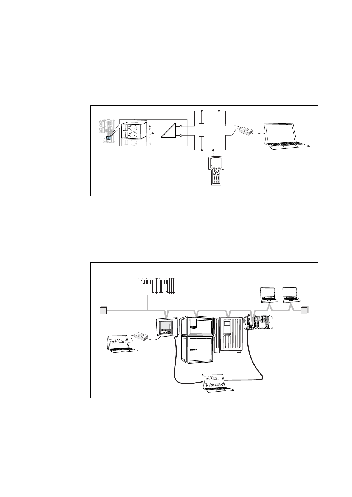
7.3 Fieldbuses
7.3.1 HART
You can communicate using the HART protocol via current output 1.
1. Connect the HART modem or HART handheld terminal to current output 1
(communication load 250 ‐ 500 Ohm).
2. Establish a connection via your HART device.
3. Operate the Liquiline via the HART device. To do so, follow the instructions in the
manual.
More detailed information on HART communication is provided on the product pages
on the Internet (→ BA00486C).
52 Endress+Hauser
Page 53

Liquiline CM44P System integration
7.3.2 PROFIBUS DP
With the fieldbus module 485 and the appropriate device version, you can communicate
via PROFIBUS DP.
Connect the PROFIBUS data cable to the terminals of the fieldbus module as described
‣
(→ 44).
For detailed information on "PROFIBUS communication", see the product pages on the
Internet (→ SD01188C).
7.3.3 Modbus
With the fieldbus module 485 and the appropriate device version, you can communicate
via Modbus RS485.
You use the BASE2 module for Modbus TCP.
The RTU and ASCII protocols are available when connecting via Modbus RS485. You can
switch to ASCII on the device.
Connect the Modbus data cable to the terminals of the fieldbus module (RS 485) or to
‣
the RJ45 socket of the BASE2 module as described.
For detailed information on "Modbus communication", see the product pages on the
Internet (→ SD01189C).
7.3.4 Ethernet/IP
With the BASE2 module and the appropriate device version, you can communicate via
Ethernet/IP.
Connect the Ethernet/IP data cable to the RJ45 socket of the BASE2 module.
‣
For detailed information on "Ethernet/IP communication", see the product pages on
the Internet (→ SD01293C).
7.3.5 PROFINET
With the BASE2 module and the appropriate device version, you can communicate via
PROFINET.
Connect the PROFINET data cable to the RJ45 socket of the BASE2 module.
‣
For detailed information on "PROFINET communication", see the product pages on the
internet (→ SD02490C).
Endress+Hauser 53
Page 54

Operation options Liquiline CM44P
1
2
3
1 2
3
4
8 Operation options
8.1 Overview
8.1.1 Display and operating elements
81 Overview of operation (using the example of the field device)
1 Display (with red display background in alarm condition)
2 Navigator (jog/shuttle and press/hold function)
3 Soft keys (function depends on menu)
8.1.2 Display
1 Menu path and/or device designation
2 Status display
3 Help if available
4 Assignment of the soft keys
A0037692
A0011764
54 Endress+Hauser
Page 55

Liquiline CM44P Operation options
Menu/Language
English
!"
Čeština
Nederlands
Français
Deutsch
Italiano
#$%
Polski
Menu/Language
English
!"
Čeština
Nederlands
Français
Deutsch
Italiano
#$%
Polski
8.2 Access to the operating menu via the local display
8.2.1 Operating concept
Pressing the soft key: selecting the menu directly
‣
Pressing the navigator: launching a function
‣
Turning the navigator: moving the cursor in the
‣
menu
Turning the navigator: selecting a value (e.g. from
‣
a list)
Pressing the navigator: accepting the new value New setting is accepted
‣
8.2.2 Locking or unlocking operating keys
Locking operating keys
1. Press the navigator for longer than 2 s.
A context menu for locking the operating keys is displayed.
You have the choice of locking the keys with or without password protection.
"With password" means that you can only unlock the keys again by entering the
correct password. Set this password here: Menu/Setup/General settings/
Extended setup/Data management/Change lock password.
Endress+Hauser 55
Page 56

Operation options Liquiline CM44P
2. Select whether to lock keys with or without a password.
The keys are locked. No more entries can be made. In the soft key bar, you will
see the symbol.
The password is 0000 when the device is delivered from the factory. Make sure to
note down any changes to the password, as otherwise you will not be able to unlock
the keypad yourself.
Unlocking operating keys
1. Press the navigator for longer than 2 s.
A context menu for unlocking the operating keys is displayed.
2. Key unlock .
The keys are unlocked immediately if you did not choose to lock with a password.
Otherwise you are asked to enter your password.
3. Only if keypad is password-protected: enter the right password.
The keys are unlocked. It is possible to access the entire onsite operation again.
The symbol is no longer visible on the display.
8.3 Configuration options
8.3.1 Display only
• You can only read the values but cannot change them.
• Typical read-only values are: sensor data and system information
• Example: Menu/Setup/Inputs/../Sensor type
8.3.2 Picklists
• You receive a list of options. In a few cases, these also appear in the form of multiple
choice boxes.
• Usually you just select one option; in rare instances you select one or more options.
• Example: Menu/Setup/General settings/Temperature unit
8.3.3 Numerical values
• You are changing a variable.
• The maximum and minimum values for this variable are shown on the display.
• Configure a value within these limits.
• Example: Menu/Operation/Display/Contrast
56 Endress+Hauser
Page 57

Liquiline CM44P Operation options
8.3.4 Actions
• You trigger an action with the appropriate function.
• You know that the item in question is an action if it is preceded by the following symbol:
• Examples of typical actions include:
• Deleting log entries
• Saving or loading configurations
• Triggering cleaning programs
• Example: Diagnostics/Logbooks/Configuration logbook/Delete all entries
8.3.5 Free text
• You are assigning an individual designation.
• Enter a text. You can use the characters in the editor for this purpose (upper-case and
lower-case letters, numbers and special characters).
• Using the soft keys, you can:
• Cancel your entries without saving the data ()
• Delete the character in front of the cursor ( )
• Move the cursor back one position ( )
• Finish your entries and save ()
• Example: Menu/Setup/General settings/Device tag
Endress+Hauser 57
Page 58

Operation options Liquiline CM44P
8.3.6 Tables
• Tables are needed to map mathematical functions .
• You edit a table by navigating through rows and columns with the navigator and
changing the values of the cells.
• You only edit the numerical values. The controller automatically takes care of the
engineering units.
• You can add lines to the table ( INSERT) or delete lines from the table ( DEL).
• Afterwards, you save the table ( SAVE).
• You can also cancel your entries any time using the soft key.
• Example: Menu/Setup/Inputs/pH/Medium comp.
58 Endress+Hauser
Page 59

Liquiline CM44P Commissioning
9 Commissioning
9.1 Function check
WARNING
L
Incorrect connection, incorrect supply voltage
Safety risks for staff and device malfunctions!
Check that all connections have been established correctly in accordance with the
‣
wiring diagram.
Ensure that the supply voltage matches the voltage indicated on the nameplate.
‣
Saving the configuration settings as a screenshot
Via the local display , you can take screenshots at any time and save them to an SD card.
1. Insert an SD card into the SD card slot in the base module.
2. Press the navigator button for at least 3 seconds.
3. In the context menu, select the Screenshot item.
The current screen is saved as a bitmap file to the SD card in the "Screenshots"
folder.
9.2 Power up
During the device startup phase, the relays and current outputs have an undefined
status for a few seconds prior to initialization. Watch out for possible effects on any
actuators which may be connected.
9.2.1 Setting the operating language
Configuring the language
If you have not already done so, close the housing cover and screw the device closed.
1. Switch on the supply voltage.
Wait for the initialization to finish.
2. Press the soft key MENU . Set your language in the top menu item.
The device can now be operated in your chosen language.
Endress+Hauser 59
Page 60

Commissioning Liquiline CM44P
9.2.2 Display behavior
Menu/Operation/Display
Function Options Info
Contrast 5 to 95 %
Factory setting
50 %
Backlight Selection
• On
• Off
• Automatic
Factory setting
Automatic
Screen rotation Selection
• Manual
• Automatic
Factory setting
Manual
Adjust the screen settings to suit your working
environment.
Backlight = Automatic
The backlighting is switched off automatically
after a short time if a button is not pressed. It
switches back on again as soon as you press the
navigator button.
Backlight = On
The backlighting does not switch off
automatically.
If Automatic is selected, the single‐channel
measured value display switches from one
channel to the next every second.
9.3 User definable screens
Menu/Operation/User definable screens
Function Options Info
Meas. screen 1 ... 6 You can create 6 measuring screens of your own
and give them a name. The functions are
identical for all 6 measuring screens.
Meas. screen Selection
• On
• Off
Factory setting
Off
Label Customized text, 20
characters
Number of lines 1 to 8
Factory setting
8
Line 1 ... 8 User interface
Label
Source of data Selection
• None
• See list in "Info" column
Factory setting
None
Measured value
Source of data is an
input
Selection
Depends on the input
Factory setting
None
Once you have defined your own measuring
screen, you can switch it on here. You can find
the new screen under User definable screens.
Name of the measuring screen
Appears in the status bar of the display.
Specify the number of measured values
displayed.
Specify the content of Label in the submenu of
each line.
Select a source of data.
‣
You can choose from the following:
• Sensor inputs
• Heartbeat diagnostics of sensor inputs
• Controller
• Current inputs
• Fieldbus signals
• Mathematical functions
• Binary inputs and outputs
• Current outputs
• Relay
• Measuring range switching
You can display different main, secondary and
raw measured values depending on the type of
input.
No options can be selected for outputs here.
60 Endress+Hauser
Page 61

Liquiline CM44P Commissioning
Menu/Operation/User definable screens
Function Options Info
Actuator type
Source of data is a
controller
Label Customized text, 20
Set label to "%0V"
1) "%0V" here stands for text that depends on the context. This text is generated automatically by the
software and inserted in place of %0V. In the simplest situations, the generated text could be the name of
the measuring channel, for example.
Selection
• None
• Bipolar
• Unipolar-
• Unipolar+
Factory setting
None
characters
1)
Action If you perform this action you accept the
For more information on controllers and
manipulated variables: → 88.
User-defined name for the parameter to be
displayed
parameter name that is automatically suggested.
Your own parameter name (Label) is lost!
9.4 Basic setup
Making basic settings
1. Switch to the Setup/Basic setup menu.
Make the following settings.
2. Device tag: Give your device any name of your choice (max. 32 characters).
3. Set date: Correct the set date if necessary.
4. Set time: Correct the set time if necessary.
For quick commissioning, you can ignore the additional settings for outputs,
relays etc. You can make these settings later in the specific menus.
5. To return to the measuring mode: press the soft key for ESC for at least one second.
Your controller now works with your basic settings. The sensors connected use
the factory settings of the sensor type in question and the individual calibration
settings that were last saved.
If you wish to configure your most important input and output parameters in the Basic
setup :
Configure the current outputs, relays, limit switches, controllers, device diagnostics and
‣
cleaning cycles with the submenus which follow the time setting.
Endress+Hauser 61
Page 62

Operation Liquiline CM44P
10 Operation
10.1 Display
10.1.1 Soft keys in measuring mode
On the bottom row of the display you can find four soft keys in the measuring screens:
• With MENU, CAL and DIAG take you directly to the specific software menu.
• With HOLD you can activate an immediate, general hold for sensors. This also sets all
the linked outputs, controllers and cleaning cycles to HOLD. Any sensor cleaning
programs that are currently running are interrupted. However, you can also start manual
sensor cleaning when a hold is active.
10.1.2 Measuring mode
There are different display modes: (press the navigator button to change the mode)
• (1) Overview of all the inputs and outputs
• (2) Main measured value of an input or output or the status of a relay
• (3) Main and secondary measured value of a sensor input
• (4) All measured values of a sensor input
• (5) Only for interface measurement:
Graphic display of the separation zone
There are also submenus:
• (6) User-definable measuring menus (only available if already defined)
Choice of previously configured screens (→ 60)
• (7) Heartbeat diagnostics
Quick overview of the health of the device and of each connected sensor that supports
Heartbeat technology
Change of channel to modes (2) - (5)
Turn the navigator.
‣
The display changes from channel to channel.
Sensor type Main value Main / secondary
measured value
Photometer Absorption (UV, NIR,
color, cell growth)
Turbidity
pH, glass pH value pH value, temperature Main value, Raw value,
Combined sensor pH
and ORP
pH, ISFET pH value pH value, temperature Main value, Raw value,
ORP ORP ORP, temperature Main value, Raw value, Offset,
Conductivity,
measured inductively
Conductivity,
measured
conductively
Oxygen, optical and
amperometric
pH value or ORP or rH
value
Conductivity,
concentration
Conductivity,
resistivity,
concentration
Oxygen Oxygen, temperature Partial pressure, Saturation ,
Absorption (UV, NIR,
color, cell growth)
Turbidity
pH value or ORP or rH
value, temperature
Conductivity,
concentration,
temperature
Conductivity, resistivity,
concentration,
temperature
All values
Measured value, 2nd Meas. value,
Raw value, Raw 2nd meas. value
Temperature, Glass Impedance
Main value, Raw value,
Temperature, Glass Impedance
Temperature
Temperature
Main value, Raw value,
Temperature
Main value, Raw value,
Temperature
Concentration, Temperature
62 Endress+Hauser
Page 63

Liquiline CM44P Operation
Sensor type Main value Main / secondary
measured value
Disinfection Chlorine or
chlorine dioxide
(depending on the
sensor)
Nitrate Nitrate Nitrate, temperature Main value, Raw value,
Turbidity Turbidity Turbidity, temperature Main value, Raw value,
Spectral absorption
coefficient (SAC)
Sludge level Turbidity Turbidity, temperature Main value, Raw value,
Ammonium, ionselective
Nitrate, ion-selective Nitrate Nitrate, temperature Main value, Raw value,
Potassium, ionselective
Interface
measurement
SAC SAC, temperature Main value, Raw value,
Ammonium Ammonium,
Potassium Potassium, temperature Main value, Raw value,
UIS UIS Main value, Raw value,
Chlorine or chlorine
dioxide, temperature
temperature
All values
Main value, Raw value,
Temperature
Temperature
Temperature
Temperature
Temperature
Main value, Raw value,
Temperature
Temperature
Temperature
Temperature
Separation zone (graphic)
Heartbeat diagnostics
(optional or with additional activation code)
• Heartbeat diagnostics screen with graphic indicators for the health of the device and
sensor and with a maintenance or (sensor-dependent) calibration timer
• Heartbeat status information on the health of the device and the condition of the sensor
→ 64
• : Sensor/device condition or maintenance timer > 20 %; no action is required
• : Sensor/device condition or maintenance timer > 5 ≤ 20 %, maintenance not yet
urgent but should be scheduled
• : Sensor/device condition or maintenance timer < 5 %, maintenance is
recommended
• The Heartbeat sensor condition is the assessment of the calibration results and the
sensor diagnostic functions.
An unhappy smiley can be due to the calibration result, the measured value status or to
the operating hours limit having been exceeded. These limits can be configured in the
sensor setup in a way that adapts the Heartbeat diagnostics to the application.
Heartbeat and NAMUR category
The Heartbeat status indicates the sensor or device condition while the NAMUR categories
(F, C, M, S) assess the reliability of the measured value. The two conditions can correlate
but do not have to.
• Example 1
• The number of remaining cleaning cycles for the sensor reaches 20% of the defined
maximum number. The Heartbeat symbol changes from to . The measured value
is still reliable so the NAMUR status signal does not change.
• If the maximum number of cleaning cycles is exceeded, the Heartbeat symbol changes
from to . While the measured value can still be reliable, the NAMUR status signal
changes to M (maintenance required).
• Example 2
The sensor breaks. The Heartbeat status changes immediately from to and the
NAMUR status signal also changes immediately to F (failure).
Endress+Hauser 63
Page 64

Operation Liquiline CM44P
10.1.3 Device status
Icons on the display alert you to special device states.
Icon Location Description
Header bar Diagnostic message "Failure"
Header bar Diagnostic message "Maintenance request"
Header bar Diagnostic message "Check"
Header bar Diagnostic message "Out of specification"
Header bar Fieldbus or TCP/IP communication active
Header bar Hold active (for sensors)
At measured value Hold for the actuator (current output, limit switch etc.) is active
At measured value
At measured value Measured value in "Bad" or "Alarm" state
At measured value Automatic temperature compensation active (for sensors)
At measured value Manual temperature compensation active (for sensors)
Header bar Simulation mode active or Memocheck SIM connected
At measured value The measured value is influenced by a simulated value
At measured value The displayed measured value is simulated (for sensors)
After the channel number Heartbeat diagnostics: condition of sensor is good
After the channel number Heartbeat diagnostics: condition of sensor is bad
After the channel number Heartbeat diagnostics: condition of sensor is OK
Header bar Controller is active
1)
An offset has been added to the measured value
1) Only pH or ORP measurement
If two or more diagnostic messages occur simultaneously, only the icon for the
message with the highest priority is shown on the display (for the order of priority
according to NAMUR, → 137).
10.1.4 Assignment views
Assignment views, e.g. Channel assignment view, appear as the last function in many
sections of the menu. You can use this function to see which actuators or functions are
connected to an input or output. The assignments appear in hierarchical order.
10.2 General settings
10.2.1 Basic settings
Menu/Setup/General settings
Function Options Info
Device tag Customized text, 32
characters
Temperature unit Selection
• °C
• °F
• K
Factory setting
°C
Select any name for your controller, e.g. use
‣
the TAG name.
64 Endress+Hauser
Page 65

Liquiline CM44P Operation
Menu/Setup/General settings
Function Options Info
Current output range Selection
• 0..20 mA
• 4..20 mA
Factory setting
4..20 mA
Failure current 0.0 to 23.0 mA
Factory setting
22.5 mA
The value for Failure current should be outside the measuring range. If you decided that your Current
output range = 0..20 mA you should set an error current between 20.1 and 23 mA. If the Current
output range = 4..20 mA you could also define a value < 4 mA as the error current.
The device allows an error current within the measuring range. In such instances pay attention to any
effects this may have on your process.
Alarm delay 0 to 9999 s
Factory setting
0 s
Device hold Selection
• Disabled
• Enabled
Factory setting
Disabled
In accordance with Namur NE43, the linear
range is from 3.8 to 20.5 mA (4..20 mA) or
from 0 to 20.5 mA (0..20 mA). If the range is
exceeded or undershot, the current value stops
at the range limit and a diagnostic message (460
or 461) is output.
The function meets NAMUR NE43.
Set the current value that should be output
‣
at the current outputs in the event of an
error.
The software displays only the errors that are
present longer than the set delay time. This
makes it possible to suppress messages that only
occur briefly and are caused by normal processspecific fluctuations.
You can enable an immediate, general hold (for
sensors) here. The function acts in the same way
as the HOLD soft key in the screens.
10.2.2 Date and time
Menu/Setup/General settings/Date/Time
Function Options Info
Set date Depends on the format Editing mode:
Day (two-digit): 01 to 31
Month (two-digit): 01 to 12
Year (four-digit): 1970 to 2106
Set time Depends on the format Editing mode:
hh (hour): 00 to 23 / 0 am to 12 pm
mm (minutes): 00 to 59
ss (seconds): 00 to 59
Endress+Hauser 65
Page 66

Operation Liquiline CM44P
Menu/Setup/General settings/Date/Time
Function Options Info
Extended setup
Date format Selection
• DD.MM.YYYY
• YYYY-MM-DD
• MM-DD-YYYY
Factory setting
DD.MM.YYYY
Time format Selection
• hh:mm am (12h)
• hh:mm (24h)
• hh:mm:ss (24h)
Factory setting
hh:mm:ss (24h)
Time zone Selection
• None
• Choice of 35 time zones
Factory setting
None
DST Selection
• Off
• Europe
• USA
• Manual
Factory setting
Off
Select a date format.
‣
Choose between 12-hour display or 24-hour
‣
display. Seconds can also be displayed with
the latter version.
None = Greenwich Mean Time (London).
The controller adapts the summertime/normal
time changeover automatically if you choose
European or American daylight saving time.
Manual means that you can specify the start and
end of daylight saving time yourself. Here, two
additional submenus are displayed in which you
specify the changeover date and time.
10.2.3 Hold settings
Menu/Setup/General settings/Hold settings
Function Options Info
Settings automatic Hold
Hold release time 0 to 600 s
Factory setting
0 s
Setup menu Selection
Diagnostics menu
Calibration active Factory setting
• Disabled
• Enabled
Factory setting
Disabled
Enabled
The hold status is maintained for the duration of
the delay time when you switch to the
measuring mode.
Decide whether the device outputs should
‣
switch to the defined hold state when the
particular menu is opened.
If a device-specific hold status is activated, any cleaning previously started is
interrupted. When a hold is active you can only start manual cleaning.
10.2.4 Logbooks
Logbooks record the following events:
• Calibration/adjustment events
• Operator events
• Diagnostic events
You define how the logbooks should store the data.
66 Endress+Hauser
Page 67

Liquiline CM44P Operation
In addition, you can also define individual data logbooks .
1. Assign the logbook name.
2. Select the measured value to be recorded.
3. Set the scan time (Scan time).
You can set the scan time individually for every data logbook.
Further information on the logbooks: → 159.
Menu/Setup/General settings/Logbooks
Function Options Info
Logbook ident Customized text, 16
characters
Event logbook Selection
• Off
• Ring buffer
• Fill up buffer
Factory setting
Ring buffer
Overflow warnings
Event logbook = Fill up buffer
Calibration logbook Selection
Diagnostic logbook
Configuration logbook
Data logbooks
New You can create a maximum of 8 data logbooks.
Logbook name Customized text, 20
Source of data Selection
Measured value Selection
• Off
• On
Factory setting
Off
characters
• Sensor inputs
• Heartbeat signals
• Controller
• Current inputs
• Fieldbus signals
• Binary inputs
• Mathematical functions
Factory setting
None
Depends on Source of data
Factory setting
None
Part of the file name when exporting a logbook
All diagnostic messages are recorded
Ring buffer
If the memory is full, the most recent entry
automatically overwrites the oldest entry.
Fill up buffer
If the memory is full, there is an overflow,i. e.
you cannot store any new values. The controller
displays a corresponding diagnostic message.
The memory then has to be cleared manually.
Decide whether you want to receive a
‣
diagnostic message if the fill buffer of the
relevant logbook overflows.
Select a data source for the logbook entries.
‣
You can choose from the following:
• Connected sensors
• Available controllers
• Current inputs
• Fieldbus signals
• Binary input signals
• Mathematical functions
You can record different measured values
depending on the data source.
Endress+Hauser 67
Page 68

Operation Liquiline CM44P
Menu/Setup/General settings/Logbooks
Function Options Info
Scan time 0:00:01 to 1:00:00
Factory setting
0:01:00
Data logbook Selection
• Ring buffer
• Fill up buffer
Factory setting
Ring buffer
Overflow warnings
Event logbook =
Fill up buffer
Add another
logbook
Finished Action This allows you to exit the New menu.
Start/stop
simultaneously
Logbook name The name of this submenu is based on the name
This menu appears several times if you have several data logbooks.
Selection
• Off
• On
Factory setting
Off
Action Only if you want to create another data logbook
Action Appears if you have created more than one data
Minimum time interval between two entries
Format: H:MM:SS
Ring buffer
If the memory is full, the most recent entry
automatically overwrites the oldest entry.
Fill up buffer
If the memory is full, there is an overflow,i. e. no
new values can be saved. The controller displays
a corresponding diagnostic message. The
memory then has to be cleared manually.
Decide whether you want to receive a
‣
diagnostic message if the fill buffer of the
relevant logbook overflows.
immediately. You add a new data logbook at a
later date using New.
logbook. With one mouse click, you can start or
stop recording all the data logbooks.
of the logbook and only appears once you have
created a logbook.
Source of data Read only This is for information purposes only. If you
Measured value
Log time left
Event logbook =
Fill up buffer
Log size
Event logbook =
Fill up buffer
Logbook name Customized text, 20
Scan time 0:00:01 to 1:00:00
Data logbook Selection
Overflow warnings
Event logbook =
Fill up buffer
Read only Displays the days, hours and minutes remaining
Read only Displays the number of entries remaining until
characters
Factory setting
0:01:00
• Ring buffer
• Fill up buffer
Factory setting
Ring buffer
Selection
• Off
• On
Factory setting
Off
want to record another value, delete this logbook
and create a new data logbook.
until the logbook is full.
the logbook is full.
You can change the name here again.
As above
Minimum time interval between two entries
Format: H:MM:SS
Ring buffer
If the memory is full, the most recent entry
automatically overwrites the oldest entry.
Fill up buffer
If the memory is full, there is an overflow, i. e. no
new values can be saved. The controller displays
a corresponding diagnostic message. The
memory then has to be cleared manually.
Decide whether you want to receive a
‣
diagnostic message if the fill buffer of the
relevant logbook overflows.
68 Endress+Hauser
Page 69

Liquiline CM44P Operation
Menu/Setup/General settings/Logbooks
Function Options Info
Line plotter Menu to define the graphic display
Axes Selection
• Off
• On
Factory setting
On
Orientation Selection
• Horizontal
• Vertical
Factory setting
Horizontal
X-Description Selection
Y-Description
Grids
Pitches
X Pitch/Grid distance 10 to 50%
Y Pitch/Grid distance
Remove Action This action removes the data logbook. Any data
• Off
• On
Factory setting
On
Factory setting
10 %
Should the axes (x, y) be displayed (On) or not
(Off)?
You can choose whether the value curves should
be displayed from left to right (Horizontal) or
from top to bottom (Vertical). If you want to
display two data logbooks simultaneously, make
sure that both logbooks have the same settings
here.
Decide whether a description should be
‣
displayed for the axes and whether gridlines
should be shown. In addition, you can also
decide whether pitches should be displayed.
Determine the pitch.
‣
that have not been saved are lost.
Example: New data logbook (Setup/General settings/Logbooks/Data logbooks/New)
1. Make the settings:
• Logbook name
Assign a name. Example: "01".
• Source of data
Select a data source. Example: Sensor connected to channel 1 (CH1).
• Measured value
Select the measured value to be recorded. Example: pH value.
• Scan time
Specify the time interval between two logbook entries.
• Data logbook
Activate the logbook: specify the data storage method.
2. ../Finished: Perform the action.
The device shows the new logbook in the list of data logbooks.
3. Select data logbook "01".
Additional display: Log time left.
4. Only in the case of Fill up buffer:
Decide to set Overflow warning: On or Off.
On: The device displays a diagnostic message in the event of memory overflow.
5. Line plotter submenu: Specify the type of graphic representation.
Endress+Hauser 69
Page 70

Operation Liquiline CM44P
10.2.5 Advanced setup
Diagnostics settings
The list of diagnostic messages displayed depends on the path selected. There are devicespecific messages, and messages that depend on what sensor is connected.
Menu/Setup/(General settings or Inputs<Sensor channel>)/Extended setup/Diagnostics settings/Diag.
behavior
Function Options Info
List of diagnostic messages
Diag. code Read only
Diagnostic message Selection
• On
• Off
Factory setting
Depends on the message
Failure current Selection
• On
• Off
Factory setting
Depends on the message
Status signal Selection
• Maintenance (M)
• Out of specification (S)
• Function check (C)
• Failure (F)
Factory setting
Depends on the message
Diag. output Selection
• None
• Alarm relay
• Binary output
• Relay 1 to n (depends on
the device version)
Factory setting
None
An alarm relay is always available, regardless of the device version. Other relays are optional.
Select the message to be changed. Only then
‣
can you make the settings for this message.
You can deactivate or reactivate a diagnostic
message here.
Deactivating means:
• No error message in the measuring mode
• No error current at the current output
Decide whether an error current should be
‣
output at the current output if the diagnostic
message display is activated.
In the event of general device errors, the
error current is output at all the current
outputs. In the event of channel-specific
errors, the error current is only output at
the assigned current output.
The messages are divided into different error
categories in accordance with NAMUR NE 107.
Decide whether you want to change a status
‣
signal assignment for your application.
You can use this function to select an output to
which the diagnostic message should be
assigned.
Before being able to assign the message to an
output you must first configure a relay output to
Diagnostics .
(Menu/Setup/Outputs: Assign the Diagnostics
function and set the Operating mode to as
assigned .)
Cleaning program
(for sensors)
Detail information Read only Here you can find more information on the
Selection
• None
• Cleaning 1
• Cleaning 2
• Cleaning 3
• Cleaning 4
Factory setting
None
Decide whether the diagnostic message
‣
should trigger a cleaning program.
You can define the cleaning programs under:
Menu/Setup/Additional functions/Cleaning.
diagnostic message and instructions on how to
resolve the problem.
70 Endress+Hauser
Page 71

Liquiline CM44P Operation
HART bus address
The list of diagnostic messages displayed depends on the path selected. There are devicespecific messages, and messages that depend on what sensor is connected.
Menu/Setup/General settings/Extended setup/HART
Function Options Info
Bus address 0 to 63
Factory setting
0
You can change the device address to integrate
several HART devices in a single network
(Multidrop mode).
If you reset the device to the factory settings (Diagnostics/Reset/Factory default),
the bus address is not reset. Your setting is retained.
PROFIBUS DP
Menu/Setup/General settings/Extended setup/PROFIBUS
Function Options Info
Enable Selection
• Off
• On
Factory setting
On
Termination Read only If the device is the last in the bus, you can
Bus address 1 to 125 If you have addressed the bus via hardware (DIP
Ident number Selection
• Automatic
• PA-Profile 3.02 (9760)
• Liquiline CM44x (155D)
• Manufacturer specific
Factory setting
Automatic
You can switch off communication at this point.
The software can then only be accessed via local
operation.
terminate via the hardware.
→ 47
switches on the module, → 47), you can only
read the address here.
If an invalid address is set via the hardware, you
have to assign a valid address for your device
either here or via the bus.
Modbus
Menu/Setup/General settings/Extended setup/Modbus
Function Options Info
Enable Selection
• Off
• On
Factory setting
On
Termination Read only If the device is the last in the bus, you can
You can switch off communication at this point.
The software can then only be accessed via local
operation.
terminate via the hardware.
→ 47
Endress+Hauser 71
Page 72

Operation Liquiline CM44P
Menu/Setup/General settings/Extended setup/Modbus
Function Options Info
Settings
Transmission Mode Selection
• TCP
• RTU
• ASCII
Factory setting
(Modbus-RS485 only)
RTU
Baudrate
Modbus-RS485 only
Parity
Modbus-RS485 only
Byte order Selection
Watchdog 0 to 999 s
Selection
• 1200
• 2400
• 4800
• 9600
• 19200
• 38400
• 57600
• 115200
Factory setting
19200
Selection
• Even (1 Stopbit)
• Odd (1 Stopbit)
• None (2 Stopbit)
Factory setting
Even (1 Stopbit)
• 1-0-3-2
• 0-1-2-3
• 2-3-0-1
• 3-2-1-0
Factory setting
1-0-3-2
Factory setting
5 s
The transmission mode is displayed depending
on the version ordered.
In the case of RS485 transmission, you can
choose between RTU and ASCII . There are no
choices for Modbus-TCP.
If no data transmission takes place for longer
than the time set, this is an indicator that
communication has been interrupted. After this
time, input values received via the Modbus are
considered to be invalid.
Web server
Menu/Setup/General settings/Extended setup/Webserver
Function Options Info
Webserver Selection
• Off
• On
Factory setting
On
Webserver TCP Port 80 Read only The Transmission Control Protocol (TCP) is an
Webserver login Selection
• Off
• On
Factory setting
On
You can switch off communication at this point.
The software can then only be accessed via local
operation.
arrangement (protocol) as to how data should be
exchanged between computers. A port is a part
of an address which assigns data segments to a
network protocol.
You can switch user administration on and off at
this point. This makes it possible to create
multiple users with password access.
72 Endress+Hauser
Page 73

Liquiline CM44P Operation
Menu/Setup/General settings/Extended setup/Webserver
Function Options Info
User administration
List of users already
created
New user:
Name Free text Create new user
Enter new user password Free text
Confirm new user
password
Change user password Free text
View/edit You can change user names or passwords or
delete users. A user is already created at the
factory: "admin" with password "admin".
1. INSERT .
Free text
2. Assign any name to the new user.
3. Select a password for the user.
4. Confirm password.
You can now change the password at
any time.
PROFINET
Menu/Setup/General settings/Extended setup/PROFINET
Function Options Info
Name of Station Read only
Factory setting
Empty character string
Symbolic name for unique identification of the
field device in a PROFINET system. The
parameter can only be written via the DCP
protocol.
Ethernet/IP or Ethernet (depending on the protocol)
If PROFINET is used, the settings in this menu are read only settings. The network
settings are made via the PROFINET-DCP protocol.
For detailed information on "PROFINET communication", see the product pages on the
internet (→ SD02490C).
All the functions and configuration options listed in the following table do not apply for
‣
PROFINET.
Endress+Hauser 73
Page 74

Operation Liquiline CM44P
Menu/Setup/General settings/Extended setup/Ethernet
Function Options Info
Enable Selection
• Off
• On
Factory setting
On
Settings
Link settings Selection
• Auto negotiation
• 10MBps Half duplex
• 10MBps Full duplex
• 100MBps Half duplex
• 100MBps Full duplex
Factory setting
Auto negotiation
DHCP Selection
• Off
• On
Factory setting
On
IP-Address xxx.xxx.xxx.xxx An IP address is an address in computer
Netmask xxx.xxx.xxx.xxx On the basis of the IP address of a device, the
Gateway x.x.x.x A gateway (protocol converter) enables
Service switch Read only
MAC-Address Read only The MAC address (Media Access Control
EtherNetIP Port 44818 Read only A port is a part of an address which assigns data
You can switch off communication at this point.
The software can then only be accessed via local
operation.
Transmission methods of the communication
channels
• Full duplex:
Data can be transmitted and received
simultaneously.
• Half-duplex:
Data can be transmitted and received on an
alternating basis only, i.e. not simultaneously.
The Dynamic Host Configuration Protocol
(DHCP) makes it possible to assign the network
configuration to clients via a server. With DHCP,
it is possible to automatically integrate the
device into an existing network without the need
for manual configuration. Normally only the
automatic assignment of the IP address must be
configured at the client. During startup, the IP
address, the netmask and the gateway are
retrieved from a DHCP server.
Do you want to assign the IP address of the
device manually? If so, you must set
DHCP= Off.
networks which are based on the Internet
protocol (IP).
You can only set the IP address if DHCP is
switched off.
netmask specifies which IP addresses this device
searches for in its own network and which
addresses it could access in other networks via a
router. It therefore divides the IP address into a
network part (network prefix) and a device part.
The network part must be identical for all
devices in the individual network, and the device
part must be different for every device within the
network.
communication between networks that are
based on completely different protocols.
address) is the hardware address of every
individual network adapter which is used to
uniquely identify the device in a computer
network.
segments to a network protocol.
74 Endress+Hauser
Page 75

Liquiline CM44P Operation
Accepting settings
Have you changed settings manually, such as the IP address?
Before you leave the Ethernet menu:
‣
SAVE Select to apply your settings.
In theDIAG/System information menu you can check whether the new settings
are used.
Data management
Firmware update
Please contact your local sales office for information on firmware updates available
for your controller and its compatibility with earlier versions.
Current firmware version : Menu/Diagnostics/System information/.
Back up your current setup and your logbooks to an SD card.
‣
To install a firmware update, you must have the update available on an SD card.
1. Insert the SD card into the controller card reader.
2. Go to Menu/Setup/General settings/Extended setup/Data management/
Firmware update .
The update files on the SD card are displayed.
3. Select the desired update and select yes when asked the following:
The current firmware will be overwritten.
After this the device will reboot.
Do you want to proceed?
The firmware is loaded and the device is then started with the new firmware.
Saving the setup
Saving a setup offers the following advantages, among others :
• Copying settings for other devices
• Quick and easy switching between various setups, e. g. for different user groups or for
recurring sensor type changes
• Restoring a tried-and-tested setup, e. g. if you have changed a lot of settings and no
longer know what the original settings were
1. Insert the SD card into the controller card reader.
2. Go to Menu/Setup/General settings/Extended setup/Data management/Save
setup .
3. Name: Assign a file name.
4. Then select Save .
If you have already assigned the file name, you will be asked whether you want to
overwrite the existing setup.
5. Use OK to confirm or cancel and assign a new file name.
Your setup is stored on the SD card and you can upload it quickly to the device at
a later date.
Loading the setup
When you load a setup, the current configuration is overwritten.
1. Insert the SD card into the controller card reader. A setup must have been saved to
the SD card.
Endress+Hauser 75
Page 76

Operation Liquiline CM44P
2. Go to Menu/Setup/General settings/Extended setup/Data management/Load
setup .
A list of all the setups on the SD card is displayed.
An error message is displayed if there is no valid setup on the card.
3. Select the desired setup.
A warning is displayed:
The current parameters will be overwritten and the device will reboot.
Warning: Please note that cleaning and controller programs can be active.
Do you want to proceed?
4. Use OK to confirm or cancel.
If you select OK to confirm, the device restarts with the desired setup.
Exporting the setup
Exporting a setup offers the following advantages, among others:
• Export in XML format with a stylesheet for formatted display in an XML-compatible
application, such as . Microsoft Internet Explorer
• Importing the data (drag and drop the XML file into a browser window)
1. Insert the SD card into the controller card reader.
2. Go to Menu/Setup/General settings/Extended setup/Data management/Export
setup .
3. Name: Assign a file name.
4. Then select Export .
If you have already assigned the file name, you will be asked whether you want to
overwrite the existing setup.
5. Use OK to confirm or cancel and assign a new file name.
Your setup is saved on the SD card in the "Device" folder.
You cannot upload the exported setup to the device again. You must use the Save
setup . This is the only way you can save a setup to an SD card and reload it later on or
upload it to other devices.
Activation code
You require activation codes for:
• Additional functions, e.g. fieldbus communication
• Firmware upgrades
• Modifications, e.g. deactivation of fieldbus protocols
If your original device has activation codes, these can be found on the nameplate. The
corresponding device functions are activated at the factory. You only require the codes
if servicing the device or deactivating fieldbus protocols.
1. Enter activation code: Menu/Setup/General settings/Extended setup/Data
management/Activation code.
2. Confirm your entry.
The new hardware or software function is activated and can be configured.
Functions that are enabled by an activation code:
Function Activation code beginning with
Second Memosens input 062...
Deactivation of fieldbus when the 485 module is removed
Two current outputs (BASE2-E module only) 081...
Web server
2)
1)
0B0...
351...
76 Endress+Hauser
Page 77

Liquiline CM44P Operation
Function Activation code beginning with
HART 0B1...
PROFIBUS DP 0B3...
Modbus TCP 0B8...
Modbus RS485 0B5...
EtherNet/IP 0B9...
PROFINET 0B7...
Measuring range switching, set 1 211...
Measuring range switching, set 2
Feedforward control 220...
Chemoclean Plus 25...
Configure the mathematical function Cation exchanger capacity 301...
Heartbeat monitoring 2D1...
Heartbeat verification 2E1...
1) The device displays an error message if you remove the 485 module with the fieldbus protocol activated.
You must now enter the activation code on the inside nameplate. The fieldbus is only deactivated once you
do this. Afterwards you must enter the appropriate activation code to activate current outputs of the base
module. Additional current outputs (CM444R and CM448R only) are activated as soon as the
corresponding module is used.
2) Via Ethernet socket of the Base2 module, for versions without an Ethernet fieldbus
3) When you order the "Measuring range switching" option, you receive two activation codes. Enter both in
order to have two sets for measuring range switching.
3)
212...
Change password
You can lock the operating keys with a password (access the context menu by pressing the
navigator for longer). The keys can then only be enabled by entering the right password.
You can set the password to lock the keys here: Menu/Setup/General settings/Extended
setup/Data management/Change lock password.
1. Enter the current password (factory setting 0000).
Enter new lock password
2. Enter a new password.
Confirm new lock password
3. Enter the new password again.
The lock password has been changed successfully.
Press the navigator for longer to return to the measuring mode.
Endress+Hauser 77
Page 78

Operation Liquiline CM44P
10.3 Inputs
10.3.1 Photometer
General settings
Menu/Setup/Inputs/Photometer
Function Options Info
Channel Selection
• Off
• On
Factory setting
On
Photometer type Selection
• OUSAF11
• OUSAF12
• OUSAF21/22
• OUSAF44/45
• OUSAF46
• OUSAF46 (2)
• OUSBT66
• OUSTF10
Factory setting
OUSAF21/22
Operating mode
Photometer type =
OUSAF21/22
Dataset Selection
Manual hold Selection
Optical path length 0.5 to 1000.0 mm
Selection
• Main value
• Main value + ref.
• 2x absorption
Factory setting
Main value + ref.
Dataset 1 ... 5
Factory setting
Dataset 1
• Off
• On
Factory setting
Off
Factory setting
10.0 mm
OUSAF46 sensors have two detectors. Therefore
you need two PEM modules to connect an
OUSAF46 sensor.
1. Select OUSAF46 for the configuration of
the first input channel to which one of the
two detectors is connected.
2. OUSAF46 (2) must be selected for the
configuration of the other input channel
to which the second detector is connected.
In the measuring mode, you can view
the measured values of both
channels, i.e. the two OUSAF46
detectors, in a user-defined view.
Main value
This operating mode uses both sensor detector
signals for absorbance measurement. The second
detector signal is used to compensate for lamp
aging or turbidity.
Main value + ref.
The absorbance of the reference wavelength can
be displayed in addition to the compensated
main measured value. The reference value can
be adapted to turbidity measurement or solids
measurement in the calibration menu of the
reference channel.
2x absorption
This operating mode uses both detector signals
independently of one another for single-channel
absorbance measurement. Both measured values
are uncompensated and can be calibrated and
adjusted individually.
You can configure datasets in the menu: CAL/
Photometer/Measurement channel
(Reference channel/2nd measurement
channel)/Application adjustment.
On
You can use this function to set the channel
manually to "Hold".
Off
No channel-specific hold
Enter the distance between the two window
surfaces (light path through the medium). The
minimum and maximum distance depends on
the cable length and the process connection.
78 Endress+Hauser
Page 79

Liquiline CM44P Operation
Menu/Setup/Inputs/Photometer
Function Options Info
Lamp voltage 2.5 to 12.0 V
Factory setting
Depends on the sensor
Lamp control input Selection
• None
• Fieldbus input
• Binary input
Factory setting
None
Switch lamp on
Switch lamp off
Action Have you checked the correct lamp voltage
The lamp voltage depends on the choice of
sensor.
1. Check the setting against the table below
with the lamp voltages of the sensors.
2. Set the correct voltage if necessary.
The lamp can be switched on and off via a binary
input or fieldbus. The voltage must be configured
once following a change of photometer type or a
change in voltage. Otherwise a diagnostic
message is displayed.
beforehand and corrected the setting if
necessary?
If so, you can now turn on the lamp.
‣
Furthermore, you can also switch off the lamp
here again and cancel the measurement.
Lamp voltages of photometer sensors
Sensor version Lamp type Lamp voltage [V]
OUSAF11-xxxxx Incandescent lamp 4.9 ± 0.1
OUSAF12-xxAxx Standard incandescent lamp 3.4 ± 0.1
OUSAF12-xxBxx Collimated incandescent lamp 4.9 ± 0.1
OUSAF12-xxCxx High-luminescence lamp 4.9 ± 0.1
OUSAF12-xxDxx Gas-filled high-performance lamp 4.9 ± 0.1
OUSAF21-xxxxx High-luminescence or gas-filled high-performance
lamp
OUSAF22-xxxxx High-luminescence or gas-filled high-performance
lamp
OUSAF44-xxxx Low-pressure mercury lamp 10.0 ± 0.1
OUSAF46-xxxx Low-pressure mercury lamp 10.0 ± 0.1
OUSTF10-xxxxx Collimated incandescent lamp 4.9 ± 0.1
OUSBT66-xxxxx LED 7.5 ± 0.1
4.9 ± 0.1
4.9 ± 0.1
Endress+Hauser 79
Page 80

Operation Liquiline CM44P
Advanced setup
Measuring channel
Menu/Setup/Inputs/Photometer/Extended setup/Measurement channel
Function Options Info
Damping 0 to 600 s
Factory setting
0 s
Calib. settings
Stability criteria You define the permitted variation in the
Delta signal 0.1 to 2.0 %
Factory setting
0.2 %
Duration 0 to 100 s
Factory setting
10 s
Calibration timer Selection
• Off
• On
Factory setting
Off
Calibration timer value 1 to 10 000 h
Factory setting
1000 h
Calib. expiration time Selection
• Off
• On
Factory setting
Off
Calib. expiration
time
Warning limit Factory setting
11 months
Alarm limit Factory setting
12 months
The damping causes a floating average curve of
the measured values over the time specified.
measured value which may not be exceeded in a
certain timeframe during calibration. If the
permitted difference is exceeded, the calibration
will not be allowed and is canceled
automatically.
Permitted measured value variation during
calibration
Timeframe within which the permitted
measured value variation may not be exceeded
Switches the function on or off
Enter the time after which the timer should time
out. When this time expires, diagnostic message
Calibration timer is displayed with code 102.
The function checks whether the calibration of a
sensor is still valid. Example: you install a precalibrated sensor. The function checks how long
ago the sensor was last calibrated. A diagnostic
message is displayed if the last calibration is
longer in the past than the prespecified warning
or alarm limit.
Warning and alarm limits mutually influence
each other's possible adjustment range. Range in
which the two limits must be: 1 to 24 months.
Generally, the following applies: alarm limit >
warning limit
Diagnostic message: 105 Calibration validity
Diagnostic message: 104 Calibration validity
80 Endress+Hauser
Page 81

Liquiline CM44P Operation
Menu/Setup/Inputs/Photometer/Extended setup/Measurement channel
Function Options Info
EasyCal Selection
• Yes
• No
Factory setting
No
NIST filter low 0.0000 to 99.9999 AU
Factory setting
0.5000 AU
NIST filter high 0.0000 to 99.9999 AU
Factory setting
1.0000 AU
Recert. date filter Enter a date
Filter value 0.0000 to 99.9999 AU
Factory setting
1.0000 AU
Filter calibration Selection
• Yes
• No
Factory setting
No
Calibration filter 0.0000 to 99.9999 AU
Factory setting
1.0000 AU
Verification filter 0.0000 to 99.9999 AU
Factory setting
0.0000 AU
Zero solution 0.0000 to 99.9999 AU
Factory setting
0.0000 AU
Standard solution 0.0000 to 99.9999 AU
Factory setting
1.0000 AU
The absorbance values mentioned above are the reference values with which the measuring point
is aligned during two-point calibration ( CALmenu).
Input optical zero Selection
• None
Input manual offset This function can be used to set the manual
• Current inputs
• Digital inputs
• Fieldbus input signal
Factory setting
None
Easycal is available for:
• OUSAF12
• OUSAF21/22
• OUSAF44/45
These 3 menu items are only displayed for the
following sensors:
OUSAF44/45
Enter the actual filter values that appear on the
factory calibration certificate of your Easycal.
Enter the recertification date specified on the
factory calibration certificate.
Applies for the following sensors:
• OUSAF12
• OUSAF21/22
Enter the actual filter values that appears on the
factory calibration certificate of your Easycal.
This menu item and the next two menu items
are only displayed for OUSBT66.
Enter the value on the certificate of the blue
calibration filter here.
Enter the value on the certificate of the red
verification filter here.
This function and the following function are not
available for OUSBT66.
Laboratory value for the absorbance of zero
solution
Laboratory value for the absorbance of standard
solution
This function can be used to set the optical zero
point via external input signals.
offset via external input signals.
2nd measurement channel (OUSAF21/22 only)
This additional menu is displayed if, under Menu/Setup/Inputs/Photometer/Operating
mode , you selected the option 2x absorption .
It has the same structure and the same configuration options as Measurement channel
(→ 80).
Endress+Hauser 81
Page 82

Operation Liquiline CM44P
Reference channel (OUSTF10 and OUSAF21/22 only)
The menu is only available for the following sensors:
• OUSTF10
The measuring channel presents the measured values of the scattered light detector,
while the reference channel presents those of the transmitted light detector.
• OUSAF21/22
The measuring channel presents the values of the first wavelength (color measurement),
while the reference channel presents those of the second wavelength (turbidity value).
The menu only has the following setting for these sensors:
Menu/Setup/Inputs/Photometer/Operating mode = Main value + ref.
Menu/Setup/Inputs/Photometer/Extended setup/Reference channel
Function Options Info
Channel Selection
• Off
• On
Factory setting
On
Damping 0 to 600 s
Factory setting
0 s
The damping causes a floating average curve of
the measured values over the time specified.
Diagnostic settings
Limits operating hours
Menu/Setup/Inputs/Photometer/Extended setup/Diagnostics settings
Function Options Info
Limits operating hours
Function Selection
• Off
• On
Factory setting
Off
Limit change filter
Warning limit 0 to 50000 h
Factory setting
10000 h
Diag. code 157
82 Endress+Hauser
Page 83

Liquiline CM44P Operation
Diagnostic behavior
The list of diagnostic messages displayed depends on the path selected. There are devicespecific messages, and messages that depend on what sensor is connected.
Menu/Setup/(General settings or Inputs<Sensor channel>)/Extended setup/Diagnostics settings/Diag.
behavior
Function Options Info
List of diagnostic messages
Diag. code Read only
Diagnostic message Selection
• On
• Off
Factory setting
Depends on the message
Failure current Selection
• On
• Off
Factory setting
Depends on the message
Status signal Selection
• Maintenance (M)
• Out of specification (S)
• Function check (C)
• Failure (F)
Factory setting
Depends on the message
Diag. output Selection
• None
• Alarm relay
• Binary output
• Relay 1 to n (depends on
the device version)
Factory setting
None
An alarm relay is always available, regardless of the device version. Other relays are optional.
Select the message to be changed. Only then
‣
can you make the settings for this message.
You can deactivate or reactivate a diagnostic
message here.
Deactivating means:
• No error message in the measuring mode
• No error current at the current output
Decide whether an error current should be
‣
output at the current output if the diagnostic
message display is activated.
In the event of general device errors, the
error current is output at all the current
outputs. In the event of channel-specific
errors, the error current is only output at
the assigned current output.
The messages are divided into different error
categories in accordance with NAMUR NE 107.
Decide whether you want to change a status
‣
signal assignment for your application.
You can use this function to select an output to
which the diagnostic message should be
assigned.
Before being able to assign the message to an
output you must first configure a relay output to
Diagnostics .
(Menu/Setup/Outputs: Assign the Diagnostics
function and set the Operating mode to as
assigned .)
Cleaning program
(for sensors)
Detail information Read only Here you can find more information on the
Selection
• None
• Cleaning 1
• Cleaning 2
• Cleaning 3
• Cleaning 4
Factory setting
None
Decide whether the diagnostic message
‣
should trigger a cleaning program.
You can define the cleaning programs under:
Menu/Setup/Additional functions/Cleaning.
diagnostic message and instructions on how to
resolve the problem.
External dataset control
The function allows you to switch between datasets for application adjustment. This
switchover is either manual or is controlled by the process control system. In this way, you
can respond to changes in your process by applying a suitable dataset in each case.
Endress+Hauser 83
Page 84

Operation Liquiline CM44P
The change in the process - for example, concentration measurement with a varying
medium composition (milk, cream, yogurt) - can be communicated to the transmitter by a
binary input signal. Binary inputs and fieldbus signals are available. For this, your device
must have the appropriate hardware and the necessary activation codes.
You can specify a maximum of 3 dataset switches. Each switch has two states (binary
encoding). Therefore you have a maximum of 23=8 signal combinations for dataset
switching.
1. Open the menu: Setup/Inputs/Photometer/Extended setup/Ext. dataset control.
2. Dataset switch 00x, Dataset switch 0x0, Dataset switch x00: First set up the
dataset switches (maximum 3 switches). You can use a binary input or one of a
maximum of 8 fieldbus signals as the signal source.
3. Then specify the dataset to be used for application adjustment for each available
signal combination (Switch equals 000, Switch equals 001 etc.), (→ 133).
Finally, activate the function (Ext. dataset control=On).
If you activate the function Ext. dataset control the dataset under Menu/Setup/
Inputs/Photometer/Dataset is for display only. You can no longer choose between
the datasets.
External hold
You can trigger a hold for all the devices of a measuring point via a digital signal, e.g. a
fieldbus signal. Make sure that you do not use the hold signal elsewhere. You can assign
an external hold individually to every sensor input.
You will only find the function in the initial menu if you have configured the signals
for the external hold in the general hold settings beforehand:
Menu/Setup/General settings/Hold settings/External hold.
Menu/Setup/Inputs/Channel: Sensor type/Extended setup/ External hold
Function Options Info
Source Selection
• Binary inputs
• Fieldbus signals
Factory setting
None
1. For selecting the signal source of the
external hold.
Multiple selection is possible.
2. OK: confirms selection.
84 Endress+Hauser
Page 85

Liquiline CM44P Operation
Cleaning hold
Menu/Setup/Inputs/Channel: Sensor type/ Extended setup
Function Options Info
Cleaning hold Selection
• None
• Cleaning 1 ... 4
Factory setting
None
For selecting one or more cleaning programs
‣
(multiple selection).
For the programs defined, the channel
goes to "Hold" while cleaning is in
progress.
Cleaning programs are executed:
• At a specified interval
For this, the cleaning program must be
started.
• If a diagnostics message is pending on the
channel and a cleaning has been specified for
this message (→ Inputs/Channel: Sensor
type/Diagnostics settings/Diag. behavior/
Diagnostic number/Cleaning program).
You define the cleaning programs in the Setup/Additional functions/Cleaning.
Sensor identification
Enter the following values (customized text) to identify the sensor:
• Serial number sensor
• Serial number assembly
• Serial number cable
10.3.2 Current inputs
The input can be used as the data source for limit switches and logbooks, for example.
Furthermore, external values can be made available as set points for controllers.
Menu/Setup/Inputs/Current input x:y
Function Options Info
Mode Selection
Input variable Selection
Meas. value format Selection
Parameter name
Input variable = Parameter
Unit of measure
Input variable = Parameter
1)
• Off
• 0 - 20mA
• 4 - 20mA
Factory setting
4 - 20mA
• Flow rate
• Parameter
• Current
Factory setting
Current
• #
• #.#
• #.##
• #.###
Factory setting
#.#
Customized text, 16
characters
Customized text, 16
characters
Select the same current range as in the data
‣
source (connected device).
Select the input variable.
‣
Specify the number of decimal places.
‣
Assign a useful name, e.g. the parameter
‣
name that the data source also uses.
You cannot choose the unit from a list. If you
want to use a unit, you must enter it here as
customized text.
Endress+Hauser 85
Page 86

Operation Liquiline CM44P
Menu/Setup/Inputs/Current input x:y
Function Options Info
Lower range value
Input variable = Parameter
Upper range value
Input variable = Parameter
Damping 0 to 60 s
1) x:y = slot no. : input number
1)
-20.0 ... Upper range
value <unit of measure>
Factory setting
0.0 <engineering unit>
Lower range value to
10000.0 <engineering
unit>
Factory setting
10.0 <engineering unit>
Factory setting
0 s
Enter the measuring range. The lower and
‣
upper range values are assigned to the 0 or
4 mA value and the 20 mA value
respectively. The system uses the
engineering unit which you entered
beforehand.
The damping causes a floating average curve of
the measured values over the time specified.
10.4 Outputs
10.4.1 Current outputs
The basic version of the device always has two current outputs.
You can configure additional current outputs with extension modules.
Setting the current output range
Menu/Setup/General settings: Select 0..20 mA or 4..20 mA.
‣
Menu/Setup/Outputs/Current output x:y
Function Options Info
Current output Selection
• Off
• On
Factory setting
Off
Source of data Selection
• None
• Connected inputs
• Controller
Factory setting
None
Measured value Selection
• None
• Depends on the Source
Factory setting
None
The list of dependent measured values is provided in the Measured value table, subject to the Source of
data→ 87.
Apart from measured values from connected sensors, you can also select a controller as the data source.
The best way to do so is by using the Additional functions menu. Here, you can select and configure the
current output for outputting the controlled variable.
Range lower value Range of adjustment and
Range upper value
factory settings depending
on the Measured value
1)
Use this function to activate or deactivate a
variable being output at the current output
The sources of data on offer depend on your
device version.
The all the sensors and controllers connected to
inputs are available for selection.
The measured value you can select depends on
the option selected under Source of data.
of data
You can output the entire measuring range or
just some of it at the current output. To do so,
specify the upper and lower range values in
accordance with your requirements.
86 Endress+Hauser
Page 87

Liquiline CM44P Operation
Menu/Setup/Outputs/Current output x:y
Function Options Info
Hold behavior Selection
• Freeze last value
• Fixed value
• Ignore
Factory setting
Depends on the
channel:output
Hold current
Hold behavior = Fixed value
1) x:y = slot:output number
0.0 to 23.0 mA
Factory setting
22.0 mA
1)
Freeze last value
The device freezes the last current value.
Fixed value
You define a fixed current value that is output at
the output.
Ignore
A hold does not affect this current output.
‣
Measured value depending on the Source of data
Source of data Measured value
Photometer Selection
• Measured value
• 2nd measurement value
• Raw meas. current
• Raw ref. current
• Lamp current
• Lamp voltage
• Raw meas. value
• Raw 2nd meas. value
pH Glass Selection
pH ISFET
ORP Selection
Oxygen (amp.) Selection
Oxygen (opt.)
Cond i Selection
Cond c
Cond c 4-pol
Disinfection Selection
ISE Selection
• Raw value mV
• pH
• Temperature
• Temperature
• ORP mV
• ORP %
• Temperature
• Partial pressure
• Concentration liquid
• Saturation
• Raw value nA
(only Oxygen (amp.))
• Raw value μs
(only Oxygen (opt.))
• Temperature
• Conductivity
• Resistance
(only Cond c)
• Concentration
(only Cond i and Cond c 4-pol)
• Temperature
• Sensor current
• Concentration
• Temperature
• pH
• Ammonium
• Nitrate
• Potassium
• Chloride
Specify which current should be output at
this current output in the hold state.
Endress+Hauser 87
Page 88

Operation Liquiline CM44P
Source of data Measured value
TU/TS Selection
TU
Nitrate Selection
Ultrasonic interface Selection
SAC Selection
Controller 1 Selection
Controller 2
Mathematical functions All the mathematical functions can also be used as a data source and the calculated
• Temperature
• Turbidity g/l
(only TU/TS)
• Turbidity FNU
(only TU/TS)
• Turbidity Formazine
(only TU)
• Turbidity solid
(only TU)
• Temperature
• NO3
• NO3-N
• Temperature
• Interface
• Turbidity
• Temperature
• SAC
• Transm.
• Absorption
• COD
• BOD
• Bipolar
(only for current outputs)
• Unipolar+
• Unipolar-
value can be used as the measured value.
Outputting the controller manipulated variable via the current output
Unipolar+ Assign to the output to which an actuator that can increase the measured value
is connected. Unipolar- Assign to the output to which an actuator that can decrease the
measured value is connected.
To output the manipulated variable of a two-sided controller, positive manipulated
variables and negative manipulated variables generally have to be output to different
actuators, as most actuators are able to influence the process in one direction only (not in
both). For this purpose, the instrument splits the bipolar manipulated variable y into two
unipolar manipulated variables, y+ and y‐.
Only the two unipolar manipulated variable parts are available for selection for outputting
to modulated relays. If outputting the values via a current output, you also have the
possibility of outputting the bipolar manipulated variable y to one current output only
(split range).
10.4.2 Alarm relay and optional relays
The basic version of the device always has one alarm relay. Additional relays are also
available depending on the version of the device.
The following functions can be output via a relay:
• Limit switch status
• Controller manipulated variable for controlling an actuator
• Diagnostic messages
• Status of a cleaning function in order to control a pump or a valve
You can assign a relay to multiple inputs in order to clean several sensors with just
one cleaning unit, for example.
88 Endress+Hauser
Page 89

Liquiline CM44P Operation
Menu/Setup/Outputs/Alarm relay or relay at channel no.
Function Options Info
Function Selection
• Off
• Limit switch
• Controller
• Diagnostics
• Cleaning
(sensor)
• Formula
(sensor)
Factory setting
• Alarm relays:
Diagnostics
• Other relays:
Off
The following functions depend on the option
selected.
These versions are illustrated individually in the
following sections to provide a clearer
understanding of the options.
Function = Off
Switches off the relay function and means no
further settings are required.
Outputting the status of a limit switch
Function = Limit switch
Function Options Info
Source of data Selection
Limit switch 1 ... 8
Factory setting
None
Hold behavior Selection
• Freeze last value
• Fixed value
• Ignore
Factory setting
Ignore
Select the limit switch via which the status of the
relay is to be output.
The limit switches are configured in the menu:
Setup/Additional functions/Limit switches.
Use the ALL and NONE soft keys to select
or deselect all the limit switches in one go.
Outputting the manipulated variable of a controller
To output a controller manipulated variable via a relay, the relay is modulated. The relay is
energized (pulse, t1) and is then de-energized (interval, t0).
Function = Controller
Function Options Info
Source of data Selection
• None
• Controller 1
• Controller 2
Factory setting
None
Operating mode Selection
• PWM
• PFM
Factory setting
PWM
Select the controller that should act as the
‣
data source.
PWM=pulse width modulation
PFM=pulse frequency modulation
Endress+Hauser 89
Page 90

Operation Liquiline CM44P
0
T
t1t
0
2T 3T
y = t / T
1
10 % 50 % 100 %
1 "High"
0 "Low"
t
1 "High"
0 "Low"
T
t
t
1
t
0
2T
y = f / f = T / T
max min
100 % 50 %
20 %
3T
1. PWM (pulse width modulation):
The duty cycle is varied within a period T (T=t1+t0). The cycle duration remains
constant.
82 Typical application: solenoid valve
2. PFM (pulse frequency modulation):
Here, pulses of a constant length (t1) are output and the interval between the pulses
varies (t0). At a maximum frequency, t1 = t0.
83 Typical application: dosing pump
Function = Controller
Function Options Info
Actuator type Selection
• None
• Unipolar(-)
• Unipolar(+)
Factory setting
None
Cycle duration
Operating mode = PWM
The settings for Cycle duration and Shortest turn-on time influence one another. The following applies:
Cycle duration ≥ Shortest turn-on time.
Shortest turn-on time
Operating mode = PWM
Shortest turn-on time to
999.0 s
Factory setting
10.0 s
0.3 s to Cycle duration
Factory setting
0.3 s
Here you specify what part of the controller
should power the relay. Unipolar(+) is the part
of the manipulated variable which the controller
uses to increase the process value (e.g. for
heating purposes). Alternatively, select
Unipolar(-) if you are connecting an actuator to
the relay that reduces the controlled variable
(e.g. for cooling purposes).
Specify the cycle duration within which the
‣
duty cycle should be varied (only PWM).
Pulses that are shorter than this limit value are
not output in order to conserve the actuator.
90 Endress+Hauser
Page 91

Liquiline CM44P Operation
Function = Controller
Function Options Info
Maximum frequency
Operating mode = PFM
Hold behavior Selection
1 to 180 min
Factory setting
60 min
• Freeze last value
• Fixed value
• Ignore
Factory setting
Ignore
-1
‐1
Maximum number of pulses per minute
The controller calculates the pulse duration
based on this setting.
Outputting diagnostic messages via the relay
If a relay is defined as a diagnostic relay (Function = Diagnostics), it works in the "failsafe mode".
This means that the relay is always energized ("normally closed", n.c.) in the basic state if
an error is not present. In this way it can also indicate a drop in voltage, for example.
The alarm relay always works in the failsafe mode.
You can output two categories of diagnostic messages via the relay:
• Diagnostic messages from one of the 4 Namur classes → 137
• Diagnostic messages which you have individually assigned to the relay output
A message is individually assigned to the relay output at 2 specific points in the menu:
• Menu/Setup/General settings/Extended setup/Diagnostics settings/Diag. behavior
(device-specific messages)
• Menu/Setup/Inputs/<Sensor>/Extended setup/Diagnostics settings/Diag. behavior
(sensor-specific messages)
Before being able to assign the relay output to a special message in Diag. behavior
you must first configure Outputs/Relay x:y or /Alarm relay/Function = Diagnostics .
Function = Diagnostics
Function Options Info
Operating mode Selection
• as assigned
• Namur M
• Namur S
• Namur C
• Namur F
Factory setting
• Relay:
as assigned
• Alarm relays:
Namur F
Attributed diagnostic messages
Operating mode = as
assigned
Read only All the messages assigned to the relay output
as assigned
If this option is selected, the diagnostic messages
which you have individually assigned to the relay
are output via the relay.
Namur M ... Namur F
If you decided to use one of the Namur classes,
all the messages that are assigned to the
individual class are output via the relay. You can
also change the Namur class assignment for
every diagnostic message.
(Menu/Setup/General settings/Extended
setup/Diagnostics settings/Diag. behavior or
Menu/Setup/Inputs/<Sensor>/Extended
setup/Diagnostics settings/Diag. behavior)
appear on the display. You do not have the
option of editing the information here.
Endress+Hauser 91
Page 92

Operation Liquiline CM44P
Outputting the status of a cleaning function
Function = Cleaning
Function Options Info
Assignments Selection
• None
• Depends on the type of
cleaning
Factory setting
None
Hold behavior Selection
• Freeze last value
• Fixed value
• Ignore
Factory setting
Ignore
Here you can specify how a cleaning function
should be displayed for the relay.
You have the following options depending on the
cleaning program that is selected (Menu/Setup/
Additional functions/Cleaning:
• Cleaning type = Standard clean
Cleaning 1 - Water, Cleaning 2 - Water,
Cleaning 3 - Water, Cleaning 4 - Water
• Cleaning type = Chemoclean
Cleaning 1 - Water, Cleaning 1 - Cleaner,
Cleaning 2 - Water, Cleaning 2 - Cleaner,
Cleaning 3 - Water, Cleaning 3 - Cleaner,
Cleaning 4 - Water, Cleaning 4 - Cleaner
• Cleaning type = Chemoclean Plus
4x Cleaning 1 - %0V, 4x Cleaning 2 - %0V
Freeze last value
The device freezes the last measured value.
Fixed value
You define a fixed measured value that is output
at the output.
Ignore
A hold has no effect.
1)
1) %0V is variable text which you can assign in Menu/Setup/Additional functions/Cleaning/Chemoclean
Plus/Output label 1 ... 4.
Formula
Function = Controller
Function Options Info
Operating mode Selection
• PWM
• PFM
Factory setting
PWM
Source of data Selection
• List of available
formulas
• Maximum of 8 formulas
Range lower value 0 to 9999
Range upper value Range lower value to
9999
Cycle duration
Operating mode = PWM
The settings for Cycle duration and Shortest turn-on time affect one another. The following applies:
Cycle duration ≥ Shortest turn-on time.
Shortest turn-on time
Operating mode = PWM
Shortest turn-on time to
999.0 s
Factory setting
10.0 s
0.3 s to Cycle duration
Factory setting
0.3 s
PWM=pulse width modulation
PFM=pulse frequency modulation→ 90
Mathematical functions of type Formula must be
available.
Select the formula which is to serve as a data
‣
source.
Specify the cycle duration within which the
‣
duty cycle should be varied (only PWM).
Pulses that are shorter than this limit value are
not output in order to conserve the actuator.
92 Endress+Hauser
Page 93

Liquiline CM44P Operation
Function = Controller
Function Options Info
Maximum frequency
Operating mode = PFM
Hold behavior Selection
1 to 180 min
Factory setting
60 min
• Freeze last value
• Fixed value
• Ignore
Factory setting
Ignore
-1
‐1
Maximum number of pulses per minute
The controller calculates the pulse duration
based on this setting.
10.4.3 HART
Specify which device variables should be output via HART communication.
You can define a maximum of 16 device variables.
1. Specify the data source.
You can choose from sensor inputs and controllers.
2. Select the measured value to be output.
3. Specify the behavior in "Hold" status. (Configuration options of Source of data,
Measured value and Hold behavior) → 87
Please note that if you select Hold behavior = Freeze , the system not only flags the status
but also actually "freezes" the measured value.
More information is provided in:
Operating Instructions "HART Communication", BA00486C
10.4.4 PROFIBUS DP and PROFINET
Device variables (device → PROFIBUS/PROFINET)
Here you can specify which process values should be mapped to the PROFIBUS function
blocks and are thereby available for transmission via PROFIBUS communication.
You can define a maximum of 16 device variables (AI Blocks).
1. Define the data source.
You can choose from sensor inputs, current inputs and mathematical functions.
2. Choose the measured value to be transmitted.
3. Define how the device should behave in the hold state. (Configuration options of
Source of data, Measured value and Hold behavior) → 87
Please note that if you select Hold behavior= Freeze , the system not only flags the status
but also actually "freezes" the measured value.
In addition, you can define 8 binary variables (DI Blocks):
1. Define the data source.
2. Select the limit switch or relay whose status is to be transmitted.
PROFIBUS/PROFINET variables (PROFIBUS/PROFINET → device)
A maximum of 4 analog (AO) and 8 digital (DO) PROFIBUS variables are available as
measured values in the controller, limit switch or current output menus.
Example: Using an AO or DO value as the set point for the controller
Endress+Hauser 93
Page 94

Operation Liquiline CM44P
Menu/Setup/Additional functions/Controller 1
1. In the specified menu, define PROFIBUS as the data source.
2. Select the desired analog output (AO) or digital output (DO) as the measured value.
Further information on "PROFIBUS" can be found in the Guideline for Communication
via PROFIBUS, SD01188C
Further information on "PROFINET" can be found in the Guideline for Communication
via PROFINET, SD02490C
10.4.5 Modbus RS485 and Modbus TCP
Specify which process values should be output via Modbus RS485 Communication or via
Modbus TCP.
In the case of Modbus RS485, you can switch between the RTU and the ASCII protocol.
You can define a maximum of 16 device variables.
1. Define the data source.
You can choose from sensor inputs and controllers.
2. Select the measured value to be output.
3. Define how the device should behave in the hold state. (Configuration options of
Source of data, Measured value and Hold behavior) → 87
Please note that if you select Hold behavior = Freeze , the system not only flags the status
but also actually "freezes" the measured value.
Further information on "Modbus" can be found in the Guideline for Communication via
Modbus, SD01189C
10.4.6 Ethernet/IP
Specify which process values should be output via EtherNet/IP communication.
You can define a maximum of 16 analog device variables (AI).
1. Define the data source.
You can choose from sensor inputs and controllers.
2. Select the measured value to be output.
3. Define how the device should behave in the hold state. (Configuration options of
Source of data, Measured value and Hold behavior) → 87
4. In the case of controllers, also specify the type of manipulated variable.
Please note that if you select Hold behavior = Freeze , the system not only flags the status
but also actually "freezes" the measured value.
In addition you can define digital device variables (DI):
Define the data source.
‣
You can choose from relays, binary inputs and limit switches.
For further information on "EtherNet/IP", see the Guideline for Communication via
EtherNet/IP, SD01293C
94 Endress+Hauser
Page 95

Liquiline CM44P Operation
CCA250
CM44x / CM44xR
Flow, e.g. Promag53
A
BU
BK
BN
CCA250
INS
47
48
91
92
CM44xX
DIO
1
2
3
Dig.in
CM44xX: DIO
Dig.in: PFM
91
92
+
–
45
46
CM44xX
DIO
Dig.out: PFM
10.5 Binary inputs and outputs
Hardware options, such as the "DIO" module with 2 digital inputs and 2 digital outputs or
fieldbus module "485" enable the following:
• Via a digital input signal
• measuring range switching for conductivity (upgrade code required, → 182)
• switching between different calibration datasets in the case of optical sensors
• external hold
• a cleaning interval to be triggered
• PID controller switch-on/switch-off, e.g. via the proximity switch of the CCA250
• the use of the input as an "analog input" for pulse-frequency modulation (PFM)
• the setting of the optical zero point or a manual offset for photometer sensors
• Via a digital output signal
• diagnostic states, point level switches, or similar states transmitted statically (similar
to a relay)
• the dynamic transmission (comparable to a non-wearing "analog output") of PFM
signals, e.g. to control dosing pumps
10.5.1 Application examples
Chlorine regulation with feedforward control
Endress+Hauser 95
84 Example of chlorine control with feedforward control
1 Connection of the inductive proximity switch INS of CCA250 to the digital input of the DIO module
2 Connection of the signal from a flowmeter to the digital input of the DIO module
3 Activation of a (pulse) dosing pump via the digital output of the DIO module
A Dosing pump
A0028316
Page 96

Operation Liquiline CM44P
CM44x / CM44xR
47
48
91
92
1 2
3
Dig.in
CM44x / CM44xR
CM44x / CM44xR
Utilize the advantage of the effectively wear-free control with binary outputs versus a
control system with relay. With pulse frequency modulation (PFM), it is possible to achieve
virtually continuous dosing using a dosing pump with higher input frequency.
1. Connect the INS proximity switch of the CCA250 assembly to a digital input of the
DIO module (e.g. slot 6, port 1).
2. In the software, configure a controller and as the source select the binary input
(e.g.Binary input 1) to which the proximity switch is connected. (Menu/Additional
functions/Controllers/Controller 1/Controller Enable = Binary input 1)
3. Signal type: For the selected input, select the factory setting (Static signal).
4. Connect the measured value of a flowmeter to the second input of the DIO module
(e.g. slot 6, port 2).
5. Signal type: for this input, select PFM . (Menu/Inputs/Binary input 6:2/Signal
type = PFM)
6. Input variable: select the corresponding measured value (Flow rate).
You can now use the input you have just configured as the disturbance variable
for your controller
2)
.
7. Disturbance variable: in the controller menu, select the binary input to which you
have connected the flow measured value. (Menu/Additional functions/Controllers/
Controller 1/Disturbance variable/Source of data = Binary input 6:2 and
Measured value = PFM value)
8. You can activate a dosing pump through PFM via a digital output of the DIO module.
Connect the pump to an output of the DIO module (e.g. slot 6, port 1) and select the
following settings in the menu: Menu/Outputs/Binary output 6:1/Signal type =
PFM and Source of data = Controller 1.
Take the direction of action of your dosing into account. Select the correct parameter
(Actuator type = Unipolar+ or Unipolar-).
You must make additional settings in the controller menu to fully customize the control to
suit your process conditions.
CM44x as the cleaning master
85 Example of a central cleaning control
1 External cleaning trigger at the binary input
2) An activation code, Order No. 71211288, is necessary for the "feedforward control" function.
2 Transferring the external hold over binary output to other measuring devices without connected cleaning
functions
3 Transferring the cleaning trigger over a binary output to other self-cleaning measuring points
1. An external trigger actuates a cleaning operation at the master.
A cleaning unit is connected via a relay or a binary output, for example.
A0028320
96 Endress+Hauser
Page 97

Liquiline CM44P Operation
2. The cleaning trigger is transferred to another device via a binary output. This does
not have its own connected cleaning unit, but its sensors are installed in the medium
affected by cleaning the master and are set to hold by the trigger.
3. The trigger is transferred via an additional binary output to another device, whose
connected sensors have their own cleaning units. The signal can be used to
simultaneously activate a self-cleaning with the master.
10.5.2 Binary input configuration
Menu/Setup/Inputs/Binary input x:y
Function Options Info
Binary input Selection
Signal type Selection
Signal type = Static signal
Signal level Selection
Signal type = PFM
Max. frequency 100.00 to 1000.00 Hz
Meas. value format Selection
1)
• Off
• On
Factory setting
On
• Static signal
• PFM
Factory setting
Static signal
• Low
• High
Factory setting
High
Factory setting
1000.00 Hz
• #
• #.#
• #.##
• #.###
Factory setting
#.##
Switches the input on/off
‣
Static signal
Use this setting to read out the position of, for
example, an on/off switch, an inductive
proximity switch or a PLC binary output.
Signal application: for measuring range
switching, acceptance of an external hold, as a
cleaning trigger or for controller activation
PFM
The PFM setting produces a pulse-frequencymodulated signal that is subsequently available
on the device as a quasi-continuous process
value.
Example: Measuring signal of a flowmeter
Specifies which input signal levels should
activate, for example, measuring range
switching or a cleaning.
Low
Input signals between 0 and 5 V DC
High
Input signals between 11 and 30 V DC
Maximum frequency of the PFM input signal
Is to equal the maximum possible upper limit of
the measuring range.
If the value selected is too small, higher
frequencies will not be detected. If the value is
too large, on the other hand, the resolution for
small frequencies will be relatively inexact.
‣
Select the signal type.
Specify the number of decimal places.
Endress+Hauser 97
Page 98

Operation Liquiline CM44P
Menu/Setup/Inputs/Binary input x:y
Function Options Info
Input variable Selection
Parameter name
Input variable = Parameter
Unit of measure
Input variable = Parameter
Flow rate unit
Input variable = Flow rate
Lower range value
Input variable = Parameter or
Flow rate
Upper range value
Input variable = Parameter or
Flow rate
Damping 0 to 60 s
1)
• Frequency
• Parameter
• Flow rate
Factory setting
Frequency
Customized text, 16
characters
Customized text, 16
characters
Selection
• l/s
• l/h
• m³/s
• m³/h
• cfs
• cfd
• mgd
Factory setting
l/s
-2000.00 to 0.00
Factory setting
0.00
0.00 to 10000.00
Factory setting
0.00
Factory setting
0 s
Frequency
Display in Hz in the measuring menu
Parameter
You subsequently determine the parameter
name and unit. These are then displayed in the
measuring menu.
Flow rate
For connecting a flowmeter
‣
‣
‣
cfs = cubic feet per second
cfd = cubic feet per day
mgd = mega gallon per day
The start of measuring range corresponds to a
frequency of 0 Hz.
Your previously defined unit is additionally
displayed.
The end of measuring range corresponds to the
maximum frequency defined above.
Your previously defined unit is additionally
displayed.
The damping causes a floating average curve of
the measured values over the time specified.
Define a name for the parameter, e.g.
"Pressure".
Specify the unit for your parameter, e.g.
"hPa".
Define the unit for the flow.
1) x:y = slot no. : input number
10.5.3 Configuration of binary outputs
Menu/Setup/Outputs/Binary output x:y
Function Options Info
Binary output Selection
Signal type Selection
1)
• Off
• On
Factory setting
On
• Static signal
• PFM
Factory setting
Static signal
Switches the output on/off
‣
Static signal
Comparable to a relay: output of a diagnostic
status or a limit switch
PFM
You can output a measured value, e. g. the
chlorine value or the manipulated variable of a
controller.
It functions as a "wear-free" switching contact
that can be used to activate a dosing pump, for
example.
Select the signal type.
98 Endress+Hauser
Page 99

Liquiline CM44P Operation
Menu/Setup/Outputs/Binary output x:y
Function Options Info
Signal type = Static signal
Function Selection
Assignments
Function = Cleaning
Data sources
Function = Limit switches
Operating mode
Function = Diagnostics
message
Signal type = PFM
Max. frequency 1.00 to 1000.00 Hz
Meas. value format Selection
1)
• None
• Limit switches
• Diagnostics message
• Cleaning
Factory setting
None
Multiple selection
• Cleaning 1 - Water ...
• Cleaning 4 - Cleaner
Multiple selection
Limit switch 1 ... 8
Selection
• as assigned
• Namur M
• Namur S
• Namur C
• Namur F
Factory setting
as assigned
Factory setting
1000.00 Hz
• #
• #.#
• #.##
• #.###
Factory setting
#.##
Source for the outputted switching state
The following functions depend on the option
selected.
Function = None Switches off the function.
There are no other settings.
Here you can decide which binary outputs should
be used for activating the valves and pumps.
Here you concretely assign a control signal to the
binary output for the cleaner/water dosing of a
cleaning program.
You can define cleaning programs under: Menu/
Setup/Additional functions/Cleaning.
‣
Configuration of the limit switches: Menu/
Setup/Additional functions/Limit switches.
as assigned
With this selection, the diagnosis messages are
transmitted over the binary output that you
individually allocated to it.
Namur M ... F
When you choose one of the Namur classes, all
messages allocated to that respective class are
output.
You can change the Namur class assignment for
every diagnostic message → 138.
Maximum frequency of the PFM output signal
Is to equal the maximum possible upper limit of
the measuring range.
‣
Select the limit switches that should be
output via the binary output.
Specify the number of decimal places.
Endress+Hauser 99
Page 100

Operation Liquiline CM44P
Menu/Setup/Outputs/Binary output x:y
Function Options Info
Source of data Selection
Measuring value
Source of data ≠ Controller
Actuator type
Source of data = Controller
Hold behavior Selection
Hold value
Hold behavior = Fixed value
Error behavior Selection
Error value
Error behavior = Fixed value
1)
• None
• Sensor inputs
• Binary inputs
• Controller
• Fieldbus signals
• Mathematical functions
Factory setting
None
Selection
Depends on:
Source of data
Selection
• None
• Bipolar
• Unipolar+
• Unipolar-
Factory setting
None
• Freeze
• Fixed value
• None
Factory setting
None
0 to 100 %
Factory setting
0 %
• Freeze
• Fixed value
Factory setting
Fixed value
0 to 100 %
Factory setting
0 %
Source, whose value should be read out as a
frequency over the binary output.
‣
‣
Bipolar
"Split range"
Unipolar+
Part of the manipulated variable that the
controller uses to increase the process value
Unipolar-
For connected actuators that decrease the
controlled variable
Freeze
The device freezes the last value.
Fixed value
You define a fixed current value that is
transmitted at the output.
None
A hold does not affect this output.
Freeze
The device freezes the last value.
Fixed value
You define a fixed current value that is
transmitted at the output.
Choose the measured value which should be
output as the frequency via the binary
output.
Determines which controller component the
connected actuator, e. g. the dosing pump,
should trigger.
1) x:y = slot no. : input number
10.6 Additional functions
10.6.1 Limit switches
There are different ways to configure a limit switch:
• Assigning a switch-on and switch-off point
• Assigning a switch-on and switch-off delay for a relay
• Setting an alarm threshold and also outputting an error message
• Starting a cleaning function
100 Endress+Hauser
 Loading...