

Page 1
TI01112C/07/EN/09.19
71478328
2019-11-30
Products Solutions Services
Technical Information
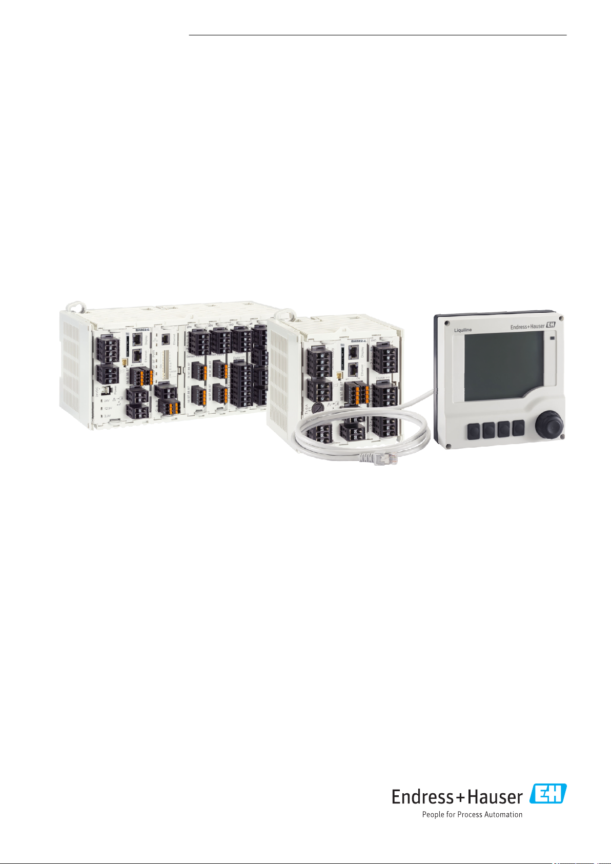
Liquiline CM442R/CM444R/
CM448R
Cabinet controller with a maximum of eight measuring
channels based on digital Memosens technology
For monitoring and controlling processes in industry and the environmental
sector
Application
• Food and beverages
• Life science
• Water and wastewater
• Chemical industry
Your benefits
• Highly flexible:
• Able to connect up to 8 Memosens sensors
• Mathematics functions calculate new measured values
• Digital fieldbuses (HART, PROFIBUS, Modbus,
Ethernet/IP, PROFINET) and integrated web server
• Choice of cleaning function, controller and alarm relay
• Optional digital or analog inputs/outputs
• Maximum process safety thanks to standardized operating
concept across all devices in the Liquiline, sampler and
analyzer platform
• Fast commissioning thanks to:
• Memosens: lab-calibrated sensors & hot plug-and-play
• Preconfigured Liquiline transmitters
• Easy extension and adaptation
• Minimum inventory:
• Cross-platform, modular concept (e.g. identical modules
irrespective of parameters)
• Integration into FieldCare and W@M facilitates effective
asset management
Page 2

Table of contents
Liquiline CM442R/CM444R/CM448R
Function and system design ................... 4
Measuring system ............................. 4
Application example ........................... 5
Device architecture .......................... 6
Slot and port assignment ........................ 6
Order of the modules ........................... 6
Basic rule for hardware upgrades ................... 6
Determining the hardware delivery status ............. 7
Terminal diagram ............................. 7
Device configuration using the example of a CM442R-
**M1A1F0* ................................ 8
Function diagram CM442R ....................... 9
Device configuration using the example of a CM444R-
**M42A1FA* .............................. 10
Function diagram CM444R ...................... 11
Device configuration using the example of a CM448R-
**26A1* .................................. 12
Function diagram CM448R ...................... 13
Communication and data processing ........... 14
Dependability ............................. 14
Reliability ................................. 14
Maintainability .............................. 16
Safety .................................... 19
Input .................................... 20
Measured variables ........................... 20
Measuring ranges ............................ 20
Types of input ............................... 20
Input signal ................................ 20
Cable specification ............................ 20
Digital inputs, passive ....................... 20
Electrical specification ......................... 20
Span ..................................... 20
Nominal input current ......................... 20
PFM function ............................... 20
Test voltage ................................ 20
Cable specification ............................ 20
Current input, passive ....................... 20
Span ..................................... 20
Signal characteristic ........................... 20
Internal resistance ............................ 20
Test voltage ................................ 20
Output .................................. 21
Output signal ............................... 21
Signal on alarm .............................. 22
Load ..................................... 22
Linearization/transmission behavior ................ 22
Digital outputs, passive ..................... 22
Electrical specification ......................... 22
External power supply ......................... 22
PFM function ............................... 22
Auxiliary voltage ............................. 22
Test voltage ................................ 22
Cable specification ............................ 22
Current outputs, active ...................... 22
Span ..................................... 22
Signal characteristic ........................... 22
Electrical specification ......................... 23
Cable specification ............................ 23
Relay outputs ............................. 24
Electrical specification ......................... 24
Cable specification ............................ 24
Protocol-specific data ....................... 24
HART .................................... 24
PROFIBUS DP ............................... 25
Modbus RS485 .............................. 25
Modbus TCP ................................ 25
Ethernet/IP ................................ 25
PROFINET ................................. 26
Web server ................................. 27
Power supply ............................. 27
Supply voltage .............................. 27
Power consumption ........................... 28
Fuse ..................................... 28
Overvoltage protection ......................... 28
Cable specification for optional display cable .......... 28
Electrical connection .......................... 29
Connecting optional modules ..................... 31
Protective ground connection .................... 33
Sensor connection ............................ 33
Performance characteristics .................. 35
Response time .............................. 35
Reference temperature ......................... 35
Measured error for sensor inputs .................. 35
Measured error for current inputs and outputs ......... 35
Frequency tolerance of digital inputs and outputs ....... 35
Resolution of current inputs and outputs ............. 35
Repeatability ............................... 35
Installation ............................... 35
Mounting on DIN rail as per IEC 60715 .............. 35
Wall mounting .............................. 36
Mounting the external display .................... 37
Environment .............................. 37
Ambient temperature range ..................... 37
Storage temperature .......................... 38
Humidity .................................. 38
Degree of protection .......................... 38
Climate class ............................... 38
Vibration resistance ........................... 38
2 Endress+Hauser
Page 3

Liquiline CM442R/CM444R/CM448R
Electromagnetic compatibility .................... 38
Electrical safety .............................. 39
Degree of contamination ....................... 39
Mechanical construction .................... 39
Dimensions ................................ 39
Weight ................................... 42
Materials .................................. 42
Operability ............................... 43
External display ............................. 43
Operating concept ............................ 43
Local operation via external, optional display .......... 43
Remote operation ............................ 44
Language packages ........................... 45
Certificates and approvals ................... 46
mark ................................... 46
EAC ..................................... 46
cCSAus ................................... 46
Marine approvals ............................ 46
Ordering information ....................... 46
Product page ............................... 46
Product Configurator .......................... 46
Scope of delivery ............................. 47
Accessories ............................... 47
Measuring cable ............................. 47
Sensors ................................... 47
Additional functionality ........................ 51
Software .................................. 53
Other accessories ............................. 53
Endress+Hauser 3
Page 4
Function and system design
1
5 4 3
2
Liquiline CM442R/CM444R/CM448R
Measuring system
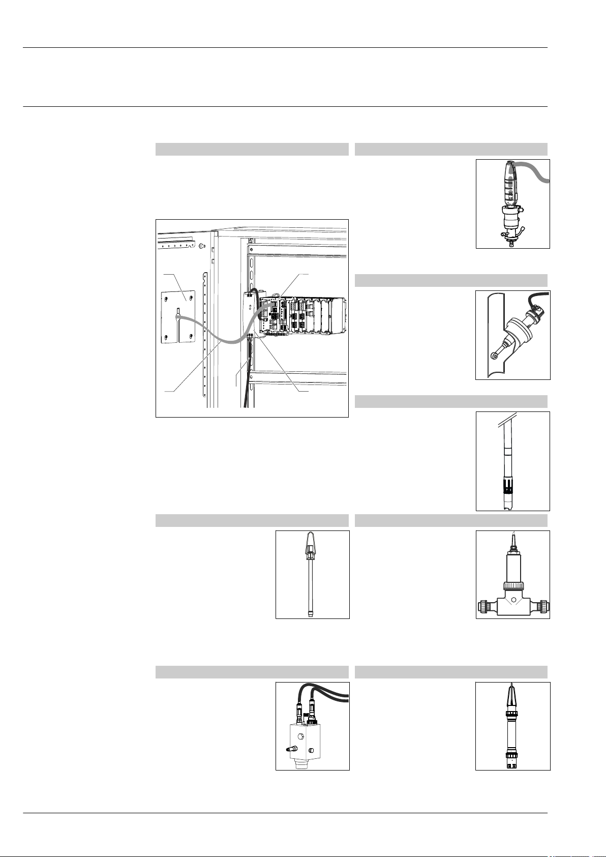
The overview shows examples of measuring systems. Other sensors and assemblies can be ordered
for conditions specific to your application (www.endress.com/products).
Measuring point pH value or ORP
A complete measuring system comprises:
• TransmitterLiquiline
• Optional display
• Sensors with Memosens technology
• Assemblies to suit the sensors used
1 Cabinet installation (without sensor and signal
cables)
1 Optional display (back)
2 Liquiline
3 External power unit (CM444R and CM448R only)
4 Power cable (to be provided by the customer)
5 Display cable
pH measurement in drinking
water (→ Fig.)
• Retractable assembly Cleanfit
CPA871
• Sensor Orbisint CPS11D
• Measuring cable CYK10
ORP in drinking water
• Dipfit CYA112 immersion
assembly
• Sensor Orbisint CPS12D
• Measuring cable CYK10
Conductivity
Inductive conductivity
measurement in wastewater
treatment
• Sensor Indumax CLS50D
• Sensor fixed cable
Conductive conductivity
measurement in power plant
cooling water
• Sensor Condumax CLS15D
• Measuring cable CYK10
Oxygen
Oxygen in aeration basins
A0042875
• Dipfit CYA112 immersion
assembly
• Holder CYH112
• Sensor
• COS61D (optical) with fixed
cable (→ Fig.)
• COS51D (amperometric),
cable CYK10
Nitrate and SAC Turbidity and interface
Nitrate in wastewater
• Sensor CAS51D-**A2 with fixed
cable
• Dipfit CYA112 immersion
assembly
• Holder CYH112
SAC in the wastewater treatment
outlet
• Sensor CAS51D-**2C2 with
fixed cable
• Dipfit CYA112 immersion
assembly
• Holder CYH112
Disinfection Ion-selective electrodes
Free available chlorine (and pH) in
drinking water
• Sensor CCS142D
• Sensor CPS11D
• Measuring cable CYK10
• Flow assembly CCA250
Turbidity in industrial water
• Sensor Turbimax CUS51D with
fixed cable (→ Fig.)
• Assembly Flowfit CUA250
• Spray head CUR3 (optional)
Interface in the primary clarifier
• Sensor Turbimax CUS71D
• Assembly CYA112
• Holder CYH112
Ammonium and nitrate
measurement in the aeration basin
• Sensor CAS40D with fixed cable
• Holder CYH112
4 Endress+Hauser
Page 5
Liquiline CM442R/CM444R/CM448R
Outlet 1
MENU
CH 1:1 pH
CH 1:1 Temperature
CH 1:2 Cond I
CH 2:1 Cond I
CH 2:2 Chlorine
CH 3:1 Current Input [Flow]
6.99 pH
25.1 °C
9.02 mS/cm
13.41 mS/cm
9.03 mg/l
15.1 nA
11:12:13 29.06.2013
10.00
mS/cm
8.00
mS/cm
29.05.2013
10:02:20
29.06.2013
11:09:15
6.00
pH
29.05.2013
10:02:20
29.06.2013
11:09:15
12.00
pH
Field Data Manager
2
1
4
3
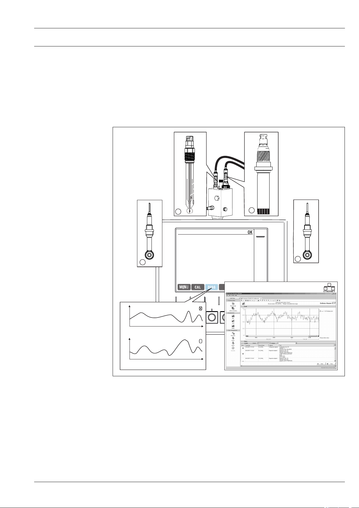
Application example
• Transmitter CM444R-AAM44A0FM6 with:
4 x Memosens, Modbus TCP, 2 digital inputs and 2 digital outputs, 2 x relays for cleaning/limit
value, 2 x analog current input
• pH and temperature with CPS11D, item 1 (www.endress.com/cps11d)
• Chlorine with CCS142D, item 4 (www.endress.com/ccs142d)
• 2 x conductivity, inductive measurement with CLS50D, item 2 and 3 (www.endress.com/cls50d)
• 1 x measuring range switching for conductivity via Modbus module
• Flow assembly CCA250 with optional proximity switch INS (www.endress.com/cca250)
• Chlorine regulation with dosing interrupted if no flow: proximity switch via digital input of DIO
module, flow feedforward control (via digital or analog input), PFM-controlled dosing pump via
digital output of DIO module
2 Measuring point in the CIP process
Data retention
• Storage of all measured values, incl. values of external sources, in the non-volatile memory
(data logbook)
• Data called up on site via user-defined measuring menu and load curve display of the data logbook
• Transmission of data by ethernet, CDI interface or SD card and storage in a tamper-proof database
(Field Data Manager)
• Data export to csv file (for Microsoft Excel)
Endress+Hauser 5
A0025347
Page 6
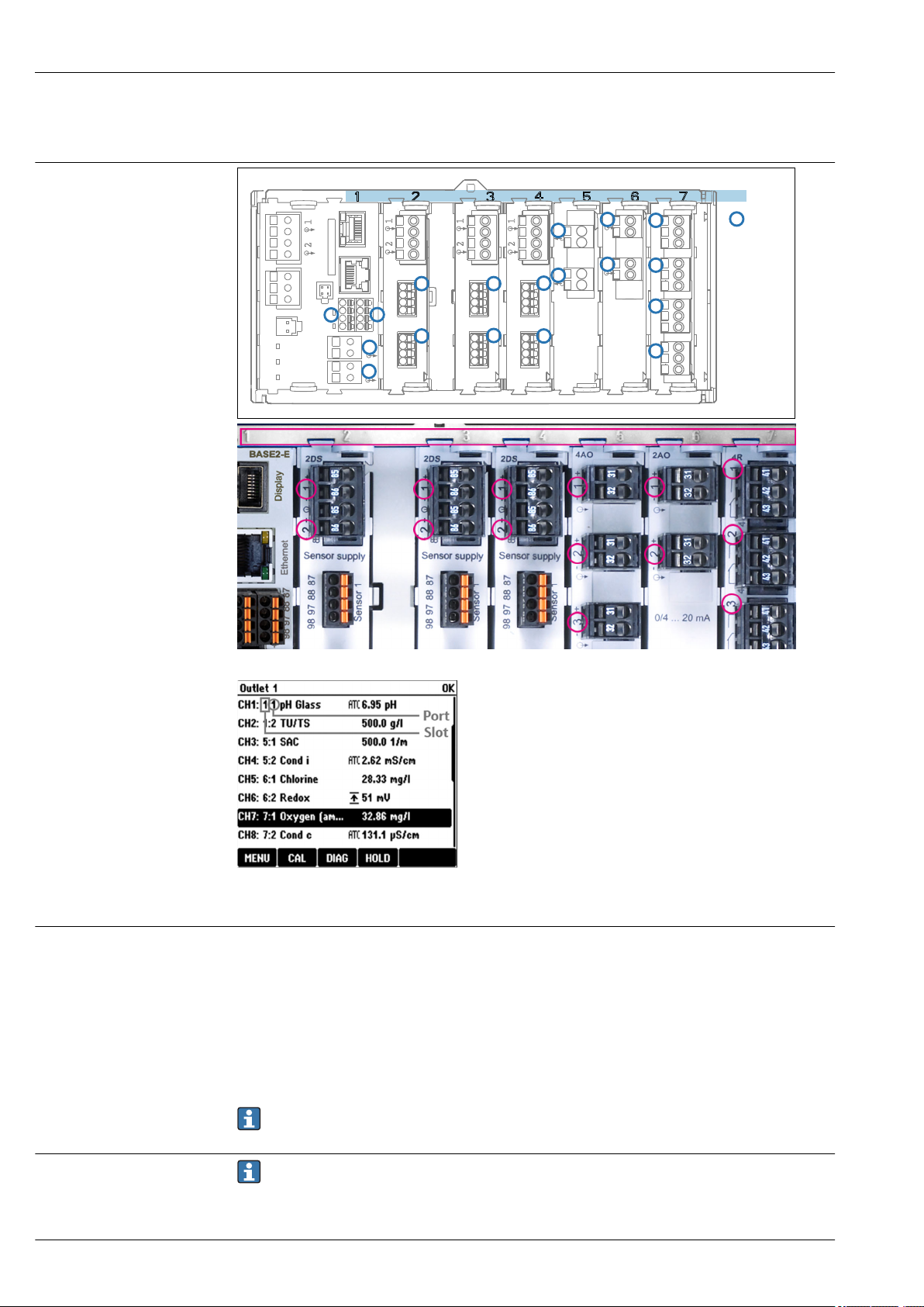
Slot and port assignment
BASE2-E
Slots
1
2
1
2
1
2
1
2
Ports
2DS 2DS 2DS 2AI 2AO 4R
1
2
Sensor 1
Sensor 1
Sensor 1
Sensor 2
Sensor 2
Sensor 2
1
2
1
2
1
2
1
2
3
4
Liquiline CM442R/CM444R/CM448R
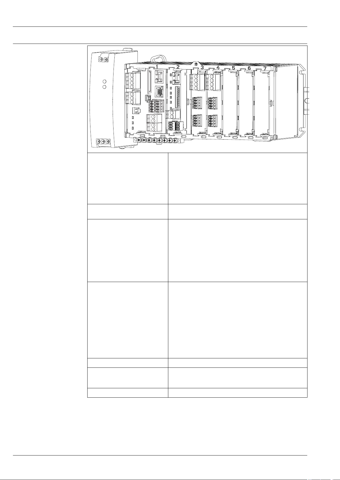
Device architecture
Order of the modules
Basic rule for hardware upgrades
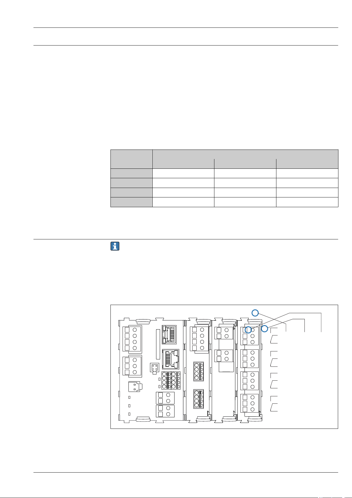
3 Slot and port assignment of the hardware modules
• Inputs are assigned to measuring channels in the
ascending order of the slots and ports.
Adjacent example:
"CH1: 1:1 pH glass" means:
Channel 1 (CH1) is slot 1 (basic module) : Port 1 (input
1), pH glass sensor
• Outputs and relays are named according to their
function, e.g. "current output", and are displayed in
ascending order with the slot and port numbers
4 Slot and port assignment on the
display
Depending on the version ordered, the device is supplied with a number of electronic modules, which
are assigned in a specific sequence in ascending order to slots 0 to 7. If you do not have a particular
module, the next moves up automatically:
• The basic module (which is always present) always occupies slots 0 and 1
• Fieldbus module 485
• Memosens input module 2DS (DS = digital sensor)
• Extension module for digital inputs and outputs DIO (DIO = digital input and output)
• Current input module 2AI (AI = analog input)
• Current output module 4AO or 2AO (AO = analog output)
• Relay modules AOR, 4R or 2R (AOR = analog output + relay, R = relay)
Modules with 4 ports are connected before modules of the same type with 2 ports.
Please note the following if upgrading the device:
• The sum of all current inputs and outputs may not exceed 8!
• A maximum of two "DIO" modules may be used.
6 Endress+Hauser
Page 7
Liquiline CM442R/CM444R/CM448R
1 2
3
4
43
42 41
Relay 1
Relay 2
Relay 3
Relay 4
Slot
Slot 4
Port 1
Pin 41
BASE2-E 2DS
4R
2AO
43
42 414342 41
43
42 41
43
42 41
Determining the hardware delivery status
You must be aware of the type of modules and the number of them supplied with the device you
have ordered to determine the delivery status of your Liquiline.
• Basic module
One basic module in all versions. Always occupies slots 0 and 1.
• Fieldbus module
Optional, and only one fieldbus module is possible.
• Input modules
• Must be clearly assigned to the number of optional inputs ordered.
• Examples:
2 current inputs = module 2AI
4 Memosens inputs = 2 inputs with basic module + module 2DS with 2 further inputs
• Current outputs and relays
Various module combinations can exist.
The following table will help you determine which modules your device has, depending on the type
and number of outputs.
Relays
Current outputs
2 - 1 x 2R 1 x 4R
4 1 x 2AO 1 x AOR 1 x 2AO + 1 x 4R
6 1 x 4AO 1 x 4AO + 1 x 2R 1 x 4AO + 1 x 4R
8 1 x 4AO + 1 x 2AO 1 x 4AO + 1 x 2AO + 1 x 2R 1 x 4AO + 1x 2AO + 1 x 4R
Sum up the number of modules and sort them according to the specified sequence → 6.
‣
0 2 4
This will give you the slot assignment for your device.
Terminal diagram
The unique terminal name is derived from:
Slot no. : Port no. : Terminal
Example, NO contact of a relay
Device with 4 inputs for digital sensors, 4 current outputs and 4 relays
• Base module BASE2-E (contains 2 sensor inputs, 2 current outputs)
• 2DS module (2 sensor inputs)
• 2AO module (2 current outputs)
• 4R module (4 relays)
5 Creating a terminal diagram using the example of the NO contact (terminal 41) of a relay
Endress+Hauser 7
A0039621
Page 8
Device configuration using
the example of a CM442R**M1A1F0*
Liquiline CM442R/CM444R/CM448R
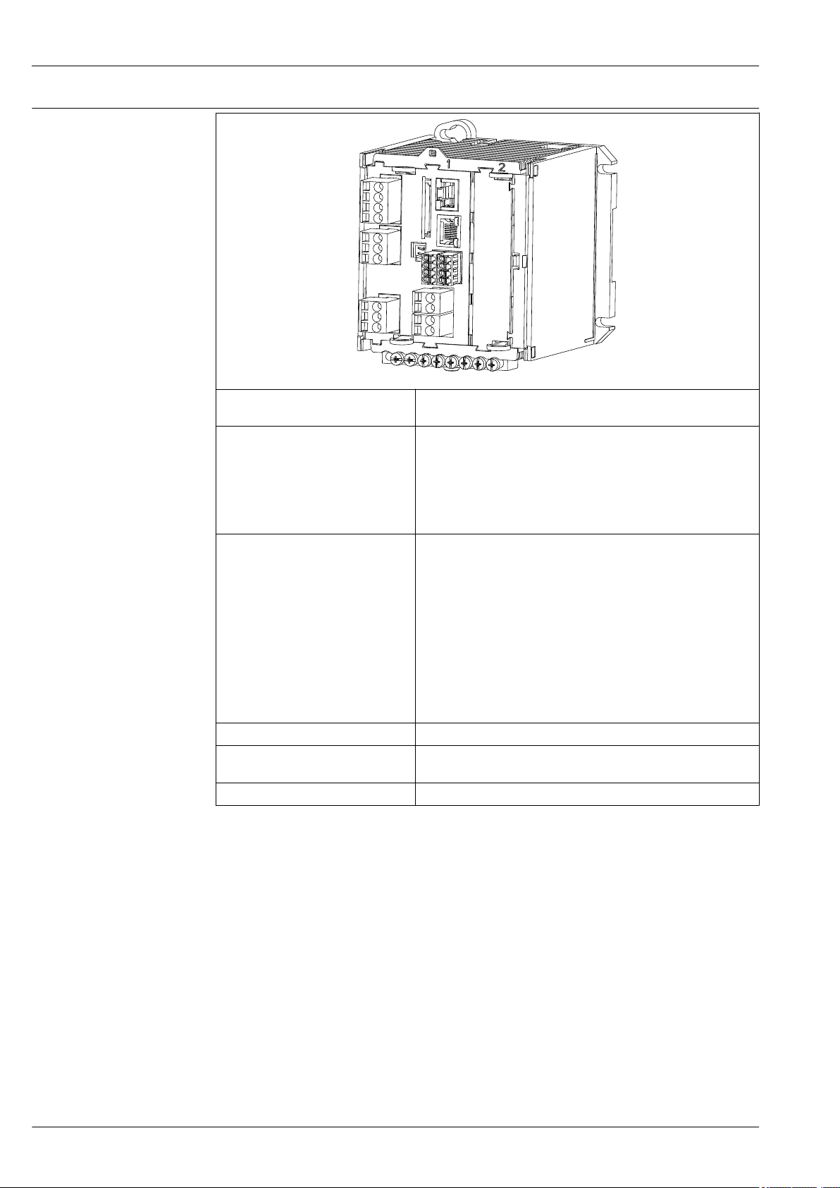
Ordered basic device (example) • Order code CM442R-**M1A1F0*
• Functionality: 1 x Memosens, 2 current outputs without HART
Extension options without additional
modules
Extension options by using an
extension module in free slot 2
Basic rule for extensions The sum of all current inputs and outputs may not exceed 8.
Restrictions if using CUS71D sensors
for interface measurement
Product Configurator www.endress.com/cm442r
Activation with activation code:
• Second Memosens input (71114663)
• HART (71128428)
• EtherNet/IP + web server (71449914)
• Modbus TCP + web server (71449915)
• PROFINET + web server (71449901)
• Web server (71449918)
PROFIBUS DP or Modbus RS485 with module 485 incl. activation
code:
• PROFIBUS DP (71140888)
• Modbus RS485 (71140889)
If module 485 is retrofitted, any existing current outputs are
disabled!
Additional inputs or outputs, relays:
• Module 2AI (71135639): 2 current inputs
• Module 2AO (71135632): 2 current outputs
• Module AOR (71111053): 2 current outputs, 2 relays
• Module 2R (71125375) or 4R (71125376): 2 or 4 relays
• Module DIO (71135638): 2 digital inputs and 2 digital outputs
Only one CUS71D can be connected. The second Memosens input
may not be used.
A0041706
8 Endress+Hauser
Page 9

Liquiline CM442R/CM444R/CM448R
mA
31
32
85
86
87
88
97
98
87
88
97
98
optional
L+L-L
N
~ =
HART
mA
31
32
optional
41
42
43
mA
31
32
mA
31
32
23
24
23
24
optional
optional
optional
optional
optional
1
2
3
3
4
2
2
5
5
6
8
8
9
10
10
10
10
7
41
42
43
41
42
43
41
42
43
41
42
43
PE
85
86
mA
mA
optional
47
48
+
–
+
–
47
48
45
46
+
–
11
45
46
+
–
91
92
91
92
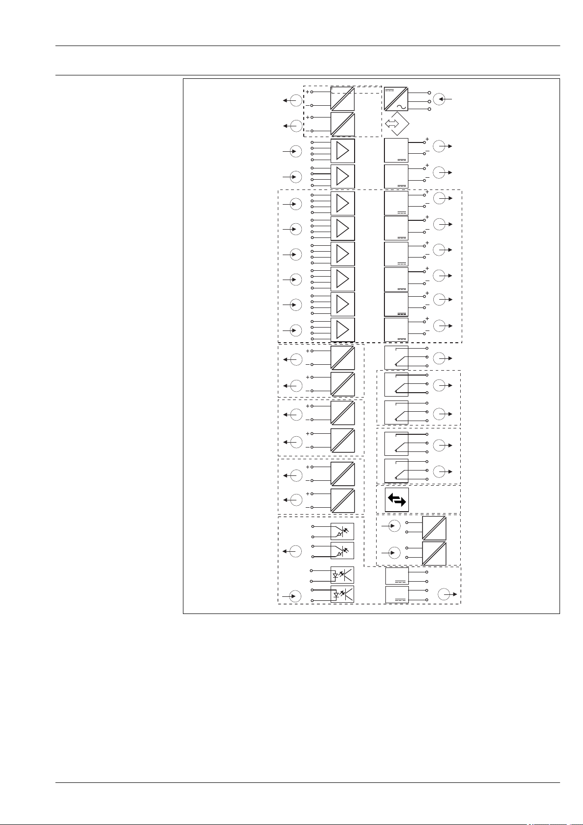
Function diagram CM442R
6 Function diagram CM442R
1 Current output 1:1, + HART (optional) 6 Power supply
Endress+Hauser 9
2 Current outputs (2 x optional) 7 Service interface
3 2 x Memosens input (1 x optional) 8 Power supply, fixed cable sensors
4 PROFIBUS DP/Modbus/Ethernet (optional) 9 Alarm relay
5 2 x current input (optional) 10 2 or 4 x relays (optional)
A0039427
11 2 digital inputs and outputs (optional)
Page 10
Device configuration using
the example of a CM444R**M42A1FA*
Liquiline CM442R/CM444R/CM448R
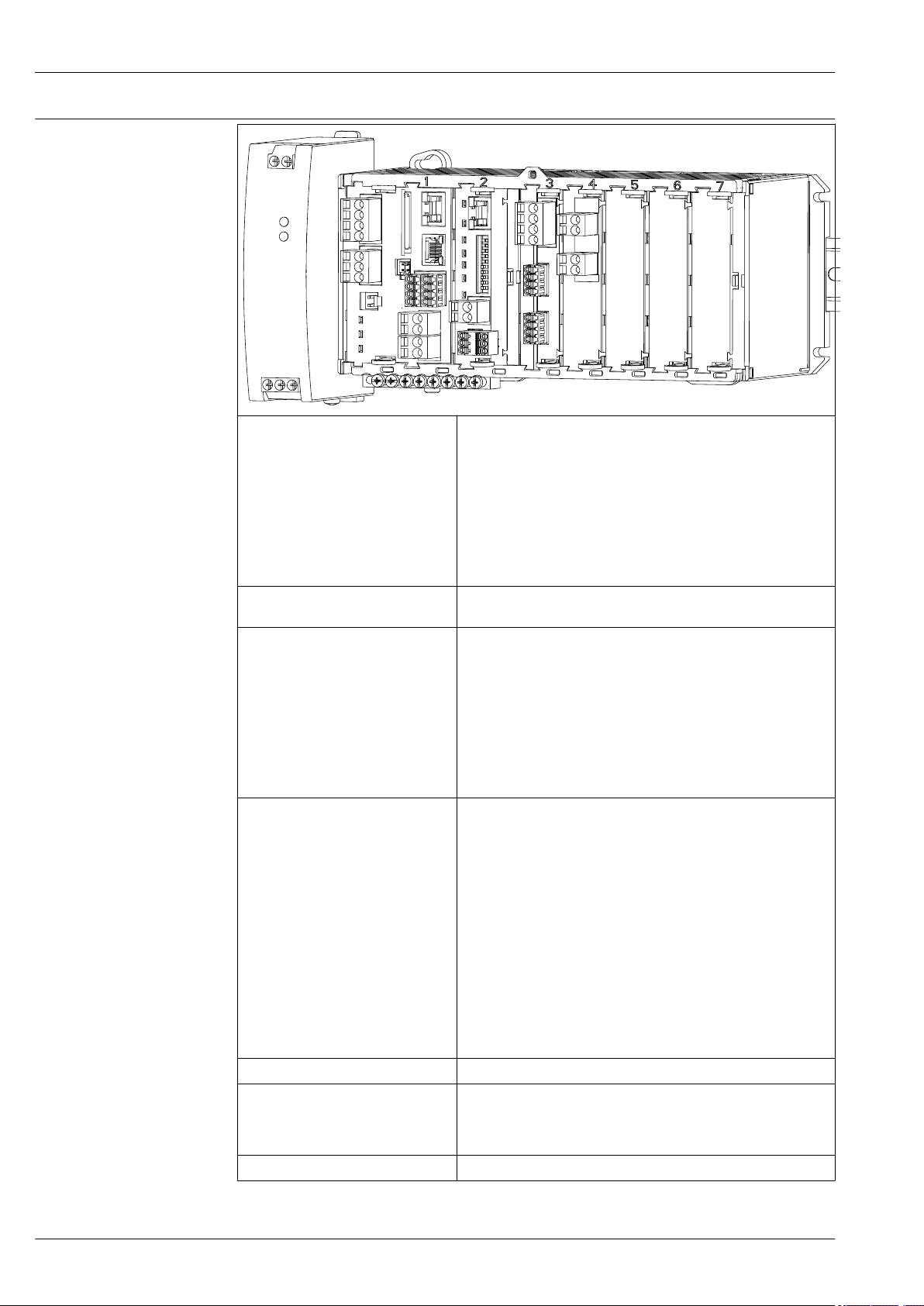
Ordered basic device (example) • Order code CM444R-**M42A1FA*
• Functionality:
• 4 x Memosens (2 on BASE2-E module + 2 on an extension
module 2DS)
• PROFIBUS communication (module 485)
• Web server (BASE2-E module)
• 2 current outputs without HART (on BASE2-E module)
• 2 current inputs (module 2AI)
3 slots are still free in this example. More or fewer slots can be free in
other versions.
Extension options without additional
modules
Modification options without
additional modules
Extension options by using extension
modules in free slots 5-7
Basic rule for extensions The sum of all current inputs and outputs may not exceed 8.
Restrictions if using CUS71D sensors
for interface measurement
Product Configurator www.endress.com/cm444r
None
Communication type changed by entering activation code. This
disables the communication type used previously!
Modbus RS485 + web server (71135636)
Retrofit by removing module 485 and entering the activation code
for:
• Modbus TCP + web server (71449915)
• EtherNet/IP + web server (71449914)
• PROFINET + web server (71449901)
• HART (71128428)
• Web server (71449918)
Only the following is possible for the example above:
• Module 2R (71125375) or 4R (71125376): 2 or 4 relays
• Module DIO (71135638): 2 digital inputs and 2 digital outputs
If extending to 8 measuring channels:
Module 2DS (71135631): 2 Memosens inputs
Additional inputs or outputs and relays if fieldbus module 485 is
removed:
• Module 2AO (71135632): 2 current outputs
• Module AOR (71111053): 2 current outputs, 2 relays
• Module 2R (71125375) or 4R (71125376): 2 or 4 relays
• Module DIO (71135638): 2 digital inputs and 2 digital outputs
If module 485 is removed and an Ethernet-based fieldbus is
used via BASE2-E module, a maximum of up to 6 current
outputs can be operated in addition. Only two current outputs
are possible with module 485.
• In the case of CM444R, every combination of Memosens sensors
(max. 4) is possible.
• An extension to CM448R is not advisable as the maximum number
of Memosens inputs when using CUS71D remains limited to 4.
10 Endress+Hauser
Page 11
Liquiline CM442R/CM444R/CM448R
mA
31
87
88
97
98
87
88
97
98
optional
optional
mA
mA
23
optional
optional
optional
optional
optional
1
2
3
3
4
2
2
5
5
6
8
8
9
10
10
10
10
7
32
31
32
31
32
24
23
24
87
88
97
98
3 8
87
88
97
98
3 8
mA
mA
optional
2
2
31
32
31
32
mA
mA
optional
2
2
31
32
31
32
HART
mA
31
32
optional
85
86
85
86
85
86
85
86
mA
mA
41
42
43
41
42
43
41
42
43
41
42
43
41
42
43
45
46
47
48
+
–
+
–
45
46
11
+
–
47
48
+
–
+
–
+
–
optional
L+L-L
N
~ =
PE
91
92
91
92
Function diagram CM444R
Endress+Hauser 11
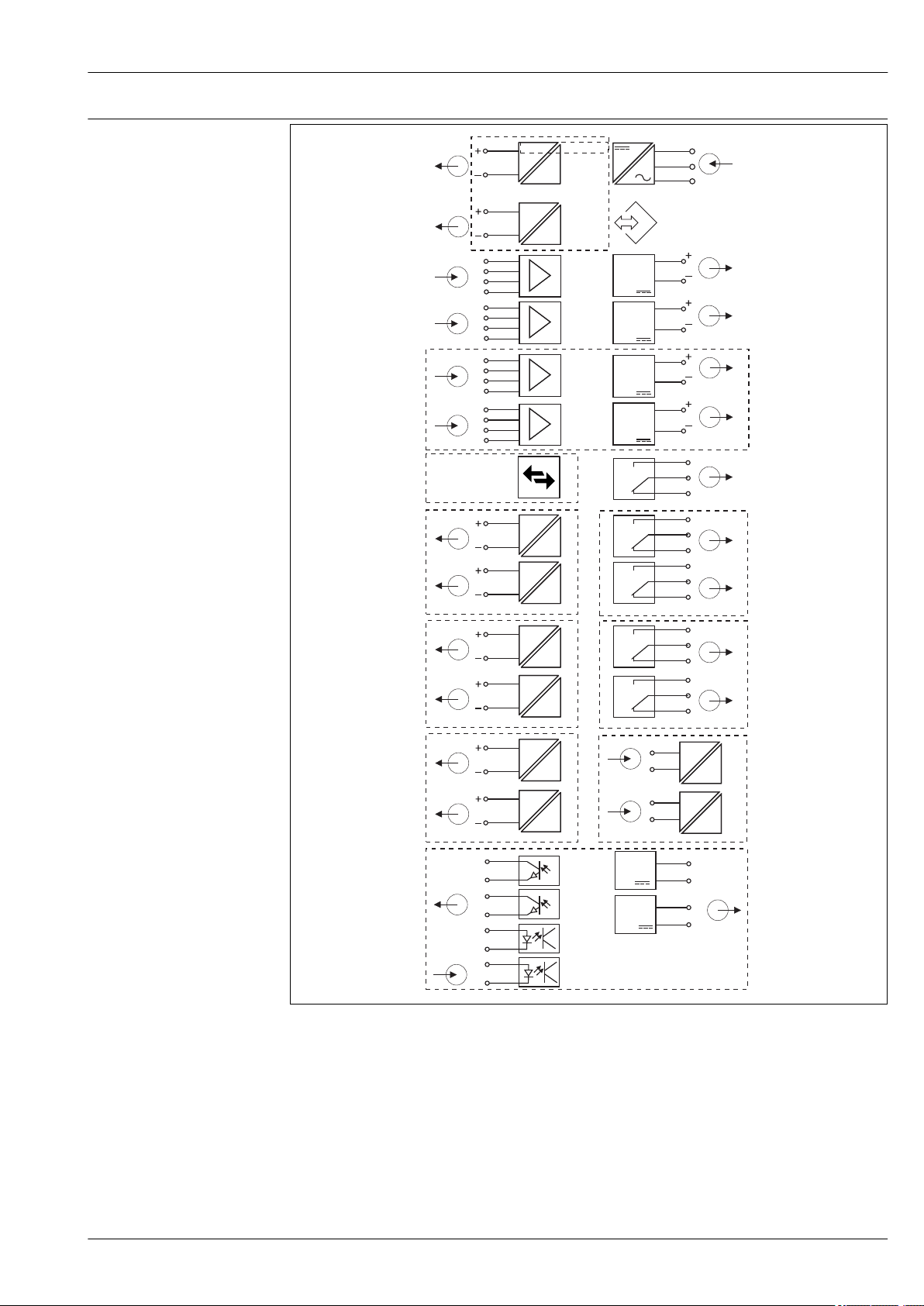
7 Function diagram CM444R
1 Current output 1:1, + HART (both optional) 6 Power supply
2 Max. 7 x current output (optional) 7 Service interface
3 Memosens input (2 x standard + 2 x optional) 8 Power supply, fixed cable sensors
4 PROFIBUS DP/Modbus/Ethernet (optional) 9 Alarm relay
5 2 x current input (optional) 10 2 or 4 x relays (optional)
A0039431
11 2 digital inputs and outputs (optional)
Page 12
Device configuration using
the example of a CM448R**26A1*
Liquiline CM442R/CM444R/CM448R
Ordered basic device (example) • Order code CM448R-**26A1*
• Functionality:
• 6 x Memosens (2 on BASE2-E module + 2 on two 2DS extension
modules)
• PROFIBUS communication (module 485)
• Web server (BASE2-E module)
3 slots are still free in this example. More or fewer slots can be free in
other versions.
Extension options without additional
modules
Modification options without
additional modules
Extension options by using extension
modules in free slots 5-7
Basic rule for extensions The sum of all current inputs and outputs may not exceed 8.
Restrictions if using CUS71D sensors
for interface measurement
Product Configurator www.endress.com/cm448r
Activation code for the use of current outputs of the basic module:
2 current outputs (71140891)
Communication type changed by entering activation code. This
disables the communication type used previously!
Modbus RS485 + web server (71135636)
Retrofit by removing module 485 and entering the activation code for
communication via the BASE2 module:
• Modbus TCP + web server (71449915)
• EtherNet/IP + web server (71449914)
• PROFINET + web server (71449901)
• HART (71128428)
• Web server (71449918)
If extending to 8 measuring channels:
Module 2DS (71135631): 2 Memosens inputs
Additional inputs or outputs, relays:
• Module 2AO (71135632): 2 current outputs
• Module 2AI (71135639): 2 current inputs
• Module AOR (71111053): 2 current outputs, 2 relays
• Module 2R (71125375) or 4R (71125376): 2 or 4 relays
• Module DIO (71135638): 2 digital inputs and 2 digital outputs
If module 485 is removed and an Ethernet-based fieldbus is
used, a maximum of up to 6 current outputs can be operated in
addition. Only two current outputs are possible with module
485.
The maximum number of Memosens inputs that can be used is
limited to 4! Here, every combination of CUS71D and other
Memosens sensors is then possible.
12 Endress+Hauser
Page 13
Liquiline CM442R/CM444R/CM448R
87
88
97
98
87
88
97
98
optional
mA
mA
optional
optional
optional
optional
1
2
3
3
4
2
2
6
8
9
10
10
10
10
7
31
32
31
32
87
88
97
98
3
87
88
97
98
3 8
mA
mA
optional
2
2
31
32
31
32
mA
mA
optional
2
2
31
32
31
32
87
88
97
98
3
8
87
88
97
98
3
8
87
88
97
98
3
87
88
97
98
3
mA
31
optional
32
HART
mA
31
32
optional
85
86
85
86
85
86
85
86
8
8
8
8
85
86
85
86
85
86
85
86
41
42
43
41
42
43
41
42
43
41
42
43
41
42
43
47
48
+
–
47
48
+
–
optional
L+L-L
N
~ =
PE
45
46
+
–
+
–
45
46
+
–
+
–
91
92
91
92
23
optional
5
5
24
23
24
mA
mA
Function diagram CM448R
Endress+Hauser 13
8 Function diagram CM448R
1 Current output 1:1, + HART (both optional) 7 Service interface
2 Max. 7 x current output (optional) 8 Power supply, fixed cable sensors
3 Max 8 x Memosens input (2 x of which are
4 PROFIBUS DP/Modbus/Ethernet (optional) 10 2 or 4 x relays (optional)
5 2 x current input (optional) 11 2 digital inputs and outputs (optional)
6 Power supply
optional)
A0039429
9 Alarm relay
Page 14

Liquiline CM442R/CM444R/CM448R
MEMO SENS
Communication and data processing
Communication protocols:
Fieldbus systems
• HART
• PROFIBUS DP (Profile 3.02)
• Modbus TCP or RS485
• PROFINET
• Ethernet/IP
Only one type of Fieldbus communication can ever be active. The last activation code entered
decides which bus is used.
The device drivers available make it possible to perform a basic setup and display measured
values and diagnostics information via the fieldbus. A full device configuration via the fieldbus
is not possible.
Extension module 485 and current outputs
For PROFIBUS DP, and Modbus RS485 communication protocols:
• CM442R
Current outputs cannot be used in parallel. Any existing current outputs are deactivated with the
installation of 485.
• CM444R/CM448R
A maximum of 2 current outputs can be used in parallel.
Ethernet functionality via Base2 module and current outputs
• CM442R
A maximum of 2 current outputs can be used in parallel.
• CM444R and CM448R
A maximum of 6 current outputs can be used in parallel.
Bus termination on the device
• Via slide switch at bus module 485
• Displayed via LED "T" on bus module 485
Reliability
Dependability
Memosens
Memosens makes your measuring point safer and more reliable:
• Non-contact, digital signal transmission enables optimum galvanic isolation
• No contact corrosion
• Completely watertight
• Sensor can be calibrated in a lab, thus increasing the availability of the measuring point in the
process
• Intrinsically safe electronics mean operation in hazardous areas is not a problem.
• Predictive maintenance thanks to recording of sensor data, e.g.:
• Total hours of operation
• Hours of operation with very high or very low measured values
• Hours of operation at high temperatures
• Number of steam sterilizations
• Sensor condition
Heartbeat diagnostics
• Heartbeat diagnostics screen with graphic indicators for the health of the device and sensor and
with a maintenance or (sensor-dependent) calibration timer
• Heartbeat status information on the health of the device and the condition of the sensor
: Sensor/device condition or maintenance timer > 20 %; no action is required
•
• : Sensor/device condition or maintenance timer > 5 ≤ 20 %, maintenance not yet urgent but
should be scheduled
• : Sensor/device condition or maintenance timer < 5 %, maintenance is recommended
• The Heartbeat sensor condition is the assessment of the calibration results and the sensor
diagnostic functions.
14 Endress+Hauser
Page 15

Liquiline CM442R/CM444R/CM448R
An unhappy smiley can be due to the calibration result, the measured value status or to the
operating hours limit having been exceeded. These limits can be configured in the sensor setup in a
way that adapts the Heartbeat diagnostics to the application.
Heartbeat and NAMUR category
The Heartbeat status indicates the sensor or device condition while the NAMUR categories (F, C, M,
S) assess the reliability of the measured value. The two conditions can correlate but do not have to.
• Example 1
• The number of remaining cleaning cycles for the sensor reaches 20% of the defined maximum
number. The Heartbeat symbol changes from
NAMUR status signal does not change.
• If the maximum number of cleaning cycles is exceeded, the Heartbeat symbol changes from
to . While the measured value can still be reliable, the NAMUR status signal changes to M
(maintenance required).
• Example 2
The sensor breaks. The Heartbeat status changes immediately from
status signal also changes immediately to F (failure).
Heartbeat Monitoring
Sensor data from Memosens sensors are transmitted via the EtherNet/IP, PROFINET, PROFIBUS DP,
HART, Modbus RTU and Modbus TCP fieldbus protocols. These data can be used for predictive
maintenance, for instance.
Examples include:
• Total hours of operation
• Hours of operation with very high or very low measured values
• Hours of operation at high temperatures
• Number of steam sterilizations
• Sensor identification
• Calibration information
For detailed information on "Ethernet/IP communication", see the product pages on the Internet
(→ SD01293C).
For detailed information on "Modbus communication", see the product pages on the Internet (→
SD01189C).
For detailed information on "PROFINET communication", see the product pages on the internet
(→ SD02490C).
For detailed information on "PROFIBUS communication", see the product pages on the Internet
(→ SD01188C).
More detailed information on HART communication is provided on the product pages on the
Internet (→ SD01187C).
to . The measured value is still reliable so the
to and the NAMUR
Heartbeat Verification
Heartbeat Verification makes it possible to verify the correct operation of the measuring device
without interrupting the process. This verification can be documented anytime.
Sensor Check System (SCS)
The Sensor Check System (SCS) monitors the high impedance of the pH glass. An alarm is issued if a
minimum impedance value is undershot or a maximum impedance is exceeded.
• Glass breakage is the main reason for a drop in high impedance values
• The reasons for increasing impedance values include:
• Dry sensor
• Worn pH glass membrane
For the SCS, upper and lower limit values can be enabled or disabled independently of one
another.
Process Check System (PCS)
The process check system (PCS) checks the measuring signal for stagnation. An alarm is triggered if
the measuring signal does not change over a specific period (several measured values).
The main causes of stagnating measured values are:
• Contaminated sensor, or sensor outside of medium
• Sensor defective
• Process error (e.g. through control system)
Endress+Hauser 15
Page 16
Liquiline CM442R/CM444R/CM448R
Self-monitoring functions
Current inputs are deactivated in the event of overcurrent and reactivated once the overcurrent
stops. Board voltages are monitored and the board temperature is also measured.
USP and EP
The limit functions for pharmaceutical water in accordance with USP and EP specifications are
implemented in the software for conductivity measurements:
• "Water for Injection" (WFI) as per USP <645> and EP
• "Highly Purified Water" (HPW) as per EP
• "Purified Water" (PW) as per EP
The uncompensated conductivity value and the temperature are measured for the USP/EP limit
functions. The measured values are compared against the tables defined in the standards. An alarm
is triggered if the limit value is exceeded. Furthermore, it is also possible to configure an early
warning alarm that signals undesired operating states before they occur.
ChemocleanPlus
Freely programmable sequence control
• e.g. for automatic sensor cleaning in retractable assemblies for reliable measurement results in
processes with a high risk of contamination
• Individual, time-based activation of 4 outputs e.g. relays
• Starting, stopping or pausing of activities via digital input or fieldbus signals e.g. from limit
position switches
Maintainability Modular design
The modular transmitter design means it can be easily adapted to suit your needs:
• Retrofit extension modules for new or extended range of functions, e.g. current outputs, relays and
digital communication
• Upgrade to maximum eight-channel measurement
• Optional: M12 sensor connector for connecting any kind of Memosens sensor
• Optional: CDI connector for external access to the service interface (avoids having to unscrew the
housing cover)
9 CM444R: example
A0042325
A0042346
10 Extension module
16 Endress+Hauser
Page 17
Liquiline CM442R/CM444R/CM448R
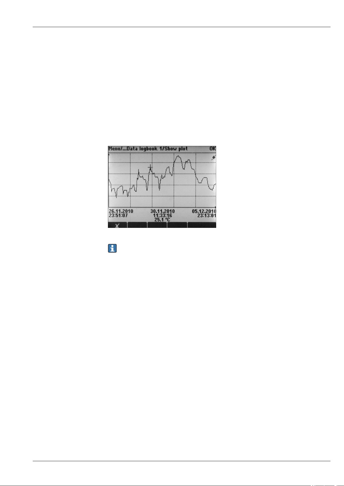
Data logger function
• Adjustable scan time: 1 to 3600 s (1 h)
• Data logbooks:
• Max. 8 data logbooks
• 150,000 entries per logbook
• Graphic display (load curves) or numerical list
• Calibration logbook: max. 75 entries
• Hardware version logbook:
• Hardware configuration and modifications
• Max. 125 entries
• Version logbook:
• E.g. software updates
• Max. 50 entries
• Operation logbook: max. 250 entries
• Diagnostics logbook: max. 250 entries
A0015032
11 Data logbook: Graphic display
Logbooks remain unchanged even after a software update.
SD card
The exchangeable storage medium enables:
• Quick and easy software updates and upgrades
• Data storage of internal device memory (e.g. logbooks)
• Transfer of complete configurations to a device with an identical setup (backup function)
• Transfer of configurations without the TAG and bus address to devices with an identical setup
(copy function)
• Saving of screenshots for documentation purposes
Endress+Hauser offers industry-approved SD cards as accessories. These memory cards provide
maximum data security and integrity.
Other SD cards up to a maximum weight of 5 g can also be used. However, Endress+Hauser does not
accept any responsibility for the data security of such cards.
External signals for device control and for activating external devices
Hardware options, e.g. module "DIO" with 2 digital inputs and 2 digital outputs or fieldbus module
"485" enable the following:
• via a digital input signal
• measuring range switching for conductivity (upgrade code required, see accessories)
• switching between different calibration datasets in the case of optical sensors
• an external hold
• a cleaning interval to be triggered
• switching on and off a PID controller, e.g. via the proximity switch of the CCA250
• the use of the input as an "analog input" for pulse-frequency modulation (PFM)
• via a digital output signal
• the static transmission (similar to a relay) of diagnostic states, point level switch states etc.
• the dynamic transmission (comparable to a non-wearing "analog output") of PFM signals, e.g. to
control dosing pumps.
Endress+Hauser 17
Page 18

Liquiline CM442R/CM444R/CM448R
FieldCare and Field Data Manager
FieldCare
Configuration and asset management software based on FDT/DTM technology
• Complete device configuration when connected via FXA291 and service interface
• Access to a number of configuration parameters and identification, measuring and diagnostic data
when connected via HART modem
• Logbooks can be downloaded in CSV format or binary format for "Field Data Manager" software
Field Data Manager
Visualization software and database for measuring, calibration and configuration data
• SQL database which is protected against manipulation
• Functions to import, save and print out logbooks
• Load curves to display measured values
A0016009
12 Field Data Manager: Load curves
Virtual process values (mathematical functions)
In addition to "real" process values, which are provided by connected physical sensors or analog
inputs, mathematical functions can be used to calculate a maximum of 8 "virtual" process values.
The "virtual" process values can be:
• Output via a current output or a fieldbus
• Used as a controlled variable
• Assigned as a measured variable to a limit switch
• Used as a measured variable to trigger cleaning
• Displayed in user-defined measuring menus
The following mathematical functions are possible:
• Calculation of pH from two conductivity values according to VGB 405 RL, e. g. in boiler feedwater
• Difference between two measured values from different sources, e. g. for membrane monitoring
• Differential conductivity, e. g. for monitoring the efficiency of ion exchangers
• Degassed conductivity, e. g. for process controls in power plants
• Redundancy for monitoring two or three redundant sensors
• rH calculation based on the measured values of a pH and an ORP sensor
• Calculation of the remaining capacity of a cation exchanger
• Formula editor
18 Endress+Hauser
Page 19

Liquiline CM442R/CM444R/CM448R
Concentration tables
When the device is delivered from the factory, tables are saved in the device that allow inductive
conductivity measurements to be converted to concentrations of certain substances. 4 user-defined
tables are also possible.
The following factory concentration tables are available:
NaOH 0 to 15 % 0 to 100 ˚C (32 to 212 ˚F)
NaOH 25 to 50% 2 to 80 ˚C (36 to 176 ˚F)
HCl 0 to 20 % 0 to 65 ˚C (32 to 149 ˚F)
HNO
H2SO40.5 to 27 % and 35 to 85 % 0 to 100 ˚C (32 to 212 ˚F)
H2SO493 to 100 % 10 to 115 ˚C (50 to 239 ˚F)
H3PO40 to 40 % 2 to 80 ˚C (36 to 176 ˚F)
NaCl 0 to 26 % 2 to 80 ˚C (36 to 176 ˚F)
Safety Real-time clock
The device has a real-time clock, which is buffered by a button cell battery if the power supply fails.
This ensures that the device continues to keep the correct date and time when it is restarted and that
the time stamp for the logbooks is correct.
0 to 30 % 2 to 80 ˚C (36 to 176 ˚F)
3
Data security
All settings, logbooks etc. are stored in a non-volatile memory to ensure that the data are retained
even in the event of a disruption to the power supply.
Measuring range switching for conductivity
• Can be used in CIP processes e.g. for safe monitoring of phase separations
• Switching between 4 complete parameter sets:
• Conductivity operating mode
• Concentration tables
• Temperature compensation
• Output signal range
• Limit value switch
• Via digital inputs or fieldbus
Measured value compensation for oxygen and conductivity
• Pressure or temperature compensation
• Input signals from external sensors via current input or fieldbus
• Signals from connected temperature sensors
Password protection
Password-protected login
• For remote operation via web server
• For local operation
Process safety
Two independent PID controllers
• One- or two-sided control
• Limit switches
• 4 cleaning programs which can be programmed independently of each other
IT security
Our warranty is valid only if the device is installed and used as described in the Operating
Instructions. The device is equipped with security mechanisms to protect it against any inadvertent
changes to the settings.
IT security measures, which provide additional protection for the device and associated data transfer,
must be implemented by the operators themselves in line with their security standards.
Endress+Hauser 19
Page 20

Input
Liquiline CM442R/CM444R/CM448R
Measured variables
Measuring ranges
Types of input
Input signal
Cable specification Cable type
→ Documentation of the connected sensor
→ Documentation of the connected sensor
• Digital sensor inputs for sensors with Memosens protocol
• Analog current inputs (optional)
• Digital inputs (optional)
Depending on version:
• Max. 8 x binary sensor signal
• 2 x 0/4 to 20 mA (optional), passive, potentially isolated from one another and from the sensor
inputs
• 0 to 30 V
Memosens data cable CYK10 or sensor fixed cable, each with cable end sleeves or M12 round-pin
connector (optional)
Cable length
Max. 100 m (330 ft)
Digital inputs, passive
Electrical specification
Span
Nominal input current
PFM function
Test voltage
Cable specification
Span
Signal characteristic
Internal resistance
• drawing power (passive)
• Galvanically isolated
• High: 11 to 30 V DC
• Low: 0 to 5 V DC
max. 8 mA
Minimum pulse width: 500 µs (1 kHz)
500 V
Max. 2.5 mm2 (14 AWG)
Current input, passive
> 0 to 20 mA
Linear
Non-linear
Test voltage
500 V
20 Endress+Hauser
Page 21

Liquiline CM442R/CM444R/CM448R
Output
Output signal
Depending on version:
• 2 x 0/4 to 20 mA, active, galvanically isolated from one another and from the sensor circuits
• 4 x 0/4 to 20 mA, active, galvanically isolated from one another and from the sensor circuits
• 6 x 0/4 to 20 mA, active, galvanically isolated from one another and from the sensor circuits
• 8 x 0/4 to 20 mA, active, galvanically isolated from one another and from the sensor circuits
• Optional HART communication (only via current output 1:1)
HART
Signal encoding FSK ± 0.5 mA via current signal
Data transmission rate 1200 baud
Galvanic isolation Yes
Load (communication resistor) 250 Ω
PROFIBUS DP/RS485
Signal encoding EIA/TIA-485, PROFIBUS DP-compliant acc. to IEC 61158
Data transmission rate 9.6 kBd, 19.2 kBd, 45.45kBd, 93.75 kBd, 187.5 kBd, 500 kBd,
1.5 MBd, 6 MBd, 12 MBd
Galvanic isolation Yes
Connectors Spring terminal (max. 1.5 mm), bridged internally (T‐function),
optional M12
Bus termination Internal slide switch with LED display
Modbus RS485
Signal encoding EIA/TIA-485
Data transmission rate 2,400, 4,800, 9,600, 19,200, 38,400, 57,600 and 115,200
baud
Galvanic isolation Yes
Connectors Spring terminal (max. 1.5 mm), bridged internally (T‐function),
optional M12
Bus termination Internal slide switch with LED display
Ethernet and Modbus TCP
Signal encoding IEEE 802.3 (Ethernet)
Data transmission rate 10/100 MBd
Galvanic isolation Yes
Connection RJ45
IP address DHCP (default) or configuration via menu
EtherNet/IP
Signal encoding IEEE 802.3 (Ethernet)
Data transmission rate 10/100 MBd
Galvanic isolation Yes
Connection RJ45
IP address DHCP (default) or configuration via menu
Endress+Hauser 21
Page 22

Liquiline CM442R/CM444R/CM448R
PROFINET
Signal encoding IEEE 802.3 (Ethernet)
Data transmission rate 100 MBd
Galvanic isolation Yes
Connection RJ45
Name of station Via DCP protocol using the configuration tool (e.g. Siemens
PRONETA)
IP address Via DCP protocol using the configuration tool (e.g. Siemens
PRONETA)
Signal on alarm
Load
Linearization/transmission behavior
Electrical specification
External power supply
Adjustable, as per NAMUR Recommendation NE 43
• In measuring range 0 to 20 mA (HART is not available with this measuring range):
Failure current from 0 to 23 mA
• In measuring range 4 to 20 mA:
Failure current from 2.4 to 23 mA
• Factory setting for failure current for both measuring ranges:
21.5 mA
Max. 500 Ω
Linear
Digital outputs, passive
• Passive
• Open collector, max. 30 V, 15 mA
• Maximum voltage drop 3 V
When using an onsite auxiliary voltage supply and an onsite digital input:
Recommended minimum auxiliary voltage = 3 V + V
(V
= minimum input voltage required (high-level input voltage)
IHmin
IHmin
PFM function
Auxiliary voltage
Minimum pulse width: 500 µs (1 kHz)
Electrical specification
• Galvanically isolated
• Unregulated, 24 V DC
• Max. 50 mA (per DIO module)
Test voltage
Cable specification
500 V
Max. 2.5 mm2 (14 AWG)
Current outputs, active
Span
Signal characteristic
22 Endress+Hauser
0 to 23 mA
2.4 to 23 mA for HART communication
Linear
Page 23

Liquiline CM442R/CM444R/CM448R
Electrical specification
Cable specification
Output voltage
Max. 24 V
Test voltage
500 V
Cable type
Recommended: shielded cable
Cable specification
Max. 2.5 mm2 (14 AWG)
Endress+Hauser 23
Page 24

Relay outputs
Liquiline CM442R/CM444R/CM448R
Electrical specification
Relay types
• 1 single-pin changeover contact (alarm relay)
• 2 or 4 single-pin changeover contacts (optional with extension modules)
Maximum load
• Alarm relay: 0.5 A
• All other relays: 2.0 A
Relay switching capacity
Base module (Alarm relay)
Switching voltage Load (max.) Switching cycles (min.)
230 V AC, cosΦ = 0.8 to 1 0.1 A 700,000
0.5 A 450,000
115 V AC, cosΦ = 0.8 to 1 0.1 A 1,000,000
0.5 A 650,000
24 V DC, L/R = 0 to 1 ms 0.1 A 500,000
0.5 A 350,000
Extension modules
Switching voltage Load (max.) Switching cycles (min.)
230 V AC, cosΦ = 0.8 to 1 0.1 A 700,000
0.5 A 450,000
2 A 120,000
115 V AC, cosΦ = 0.8 to 1 0.1 A 1,000,000
0.5 A 650,000
2 A 170,000
24 V DC, L/R = 0 to 1 ms 0.1 A 500,000
0.5 A 350,000
2 A 150,000
Cable specification
Max. 2.5 mm2 (14 AWG)
Protocol-specific data
HART
24 Endress+Hauser
Manufacturer ID 11
Device type 155D
Device revision 001
HART version 7.2
Device description files (DD/DTM) www.endress.com/hart
Device variables 16 user-definable and 16 predefined device variables, dynamic
Supported features PDM DD, AMS DD, DTM, Field Xpert DD
h
h
h
Device Integration Manager DIM
variables PV, SV, TV, QV
Page 25

Liquiline CM442R/CM444R/CM448R
PROFIBUS DP
Modbus RS485
Manufacturer ID 11
Device type 155D
h
h
Profile version 3.02
GSD files www.endress.com/profibus
Device Integration Manager DIM
Output values 16 AI blocks, 8 DI blocks
Input variables 4 AO blocks, 8 DO blocks
Supported features • 1 MSCY0 connection (cyclical communication, master class 1
to slave)
• 1 MSAC1 connection (acyclical communication, master class 1
to slave)
• 2 MSAC2 connections (acyclical communication, master class
2 to slave)
• Device lock: The device can be locked using the hardware or
software.
• Addressing using DIL switches or software
• GSD, PDM DD, DTM
Protocol RTU/ASCII
Function codes 03, 04, 06, 08, 16, 23
Broadcast support for function codes 06, 16, 23
Output data 16 measured values (value, unit, status), 8 digital values (value,
status)
Input data 4 setpoints (value, unit, status), 8 digital values (value, status),
diagnostic information
Supported features Address can be configured using switch or software
Modbus TCP
Ethernet/IP
TCP port 502
TCP connections 3
Protocol TCP
Function codes 03, 04, 06, 08, 16, 23
Broadcast support for function codes 06, 16, 23
Output data 16 measured values (value, unit, status), 8 digital values (value,
status)
Input data 4 setpoints (value, unit, status), 8 digital values (value, status),
diagnostic information
Supported features Address can be configured using DHCP or software
Log EtherNet/IP
ODVA certification Yes
Device profile Generic device (product type: 0x2B)
Manufacturer ID 0x049E
Device type ID 0x109C
h
h
Polarity Auto-MIDI-X
Connections CIP 12
I/O 6
Explicit message 6
Multicast 3 consumers
Minimum RPI 100 ms (default)
Endress+Hauser 25
Page 26

Liquiline CM442R/CM444R/CM448R
Maximum RPI 10000 ms
System integration EtherNet/IP EDS
Rockwell Add-on-Profile Level 3, Faceplate for Factory
Talk SE
IO data Input (T → O) Device status and diagnostic message with
highest priority
Measured values:
• 16 AI (analog input) + Status + Unit
• 8 DI (discrete input) + Status
Output (O → T) Actuating values:
• 4 A0 (analog output) + status + unit
• 8 DO (discrete output) + Status
PROFINET
Protocol "Application layer protocol for decentral device periphery and
distributed automation", PNIO Version 2.34
Communication type 100 MBit/s
Conformance Class Conformance Class B
Netload Class Netload Class II
Baud rate Automatic 100 Mbps with full-duplex detection
Cycle times From 32 ms
Device profile Application interface identifier 0xF600
Generic device
PROFINET interface 1 port, Realtime Class 1 (RT_CLASS_1)
Manufacturer ID 0x11
Device type ID 0x859C D
Device description files (GSD) Information and files under:
Polarity Auto-polarity for automatic correction of crossed TxD and RxD
Supported connections • 1 x AR (IO Controller AR)
Configuration options for measuring device • Web browser
Configuration of the device name DCP protocol
h
h
• www.endress.com
On the product page for the device: Documents/Software →
Device drivers
• www.profibus.com
On the website under Products/Product Finder
pairs
• 1 x AR (IO-Supervisor Device AR connection allowed)
• 1 x Input CR (Communication Relation)
• 1 x Output CR (Communication Relation)
• 1 x Alarm CR (Communication Relation)
• Manufacturer-specific software (FieldCare, DeviceCare)
• Device master file (GSD), can be read out via the integrated
web server of the measuring device
26 Endress+Hauser
Page 27

Liquiline CM442R/CM444R/CM448R
Supported functions • Identification & Maintenance
System integration For information on system integration, see the Operating
Simple device identification via:
• Process control system
• Nameplate
• Measured value status
The process variables are communicated with a measured
value status
• Blinking feature (FLASH_ONCE) via the local display for
simple device identification and assignment
• Device operation via operating tools (e.g. FieldCare,
DeviceCare)
Instructions
• Cyclic data transmission
• Overview and description of the modules
• Status coding
• Startup configuration
• Factory setting
Web server
Supply voltage
The Web server enables full access to the device configuration, measured values, diagnostic
messages, logbooks and service data via standard WiFi/WLAN/LAN/GSM or 3G routers with a userdefined IP address.
TCP port 80
Supported features • Remote-controlled device configuration(1 session)
• Save/restore device configuration (via SD card)
• Logbook export (file formats: CSV, FDM)
• Access to Web server via DTM or Internet Explorer
• Login
• Web server can be switched off
Power supply
CM442 R
Depending on version:
• 100 to 230 V AC, 50/60 Hz
Maximum permitted fluctuation of mains supply voltage: ± 15 % of nominal voltage
• 24 V AC/DC, 50/60 Hz
Maximum permitted fluctuation of mains supply voltage: + 20/- 15 % of nominal voltage
CM444 R and CM448 R
Depending on the version, via external DIN rail power unit:
• 100 to 230 V AC, 50/60 Hz
Maximum permitted fluctuation of mains supply voltage: ± 15 % of nominal voltage
• 24 V DC
Maximum permitted fluctuation of mains supply voltage: + 20/- 15 % of nominal voltage
1)
1)
NOTICE
The device does not have a power switch!
Provide a protected circuit breaker in the vicinity of the device at the place of installation.
‣
The circuit breaker must be a switch or power switch, and must be labeled as the circuit breaker
‣
for the device.
At the supply point, the power supply must be isolated from dangerous live cables by double or
‣
reinforced insulation in the case of devices with a 24 V supply voltage.
1) *Specifications only apply if used with power unit supplied by manufacturer.
Endress+Hauser 27
Page 28

Liquiline CM442R/CM444R/CM448R
Power consumption
Fuse
Overvoltage protection
Cable specification for optional display cable
CM442 R
Depending on supply voltage
• 100 to 230 V AC and 24 V AC:
Max. 55 VA
• 24 V DC:
Max. 22 W
CM444 R and CM448 R
Depending on supply voltage
• 100 to 230 V AC:
Max. 150 VA
• 24 V DC:
Max. 59 W
1)
1)
Fuse not exchangeable
Integrated overvoltage/lightning protection as per EN 61326
Protection category 1 and 3
Length of display cable provided:
3 m (10 ft)
Maximum permitted length of a display cable:
5 m (16.5 ft)
28 Endress+Hauser
Page 29

Liquiline CM442R/CM444R/CM448R
1 2
3
4
5
6
7
9
8
1 2
3
4
5
6
8
9
10
7
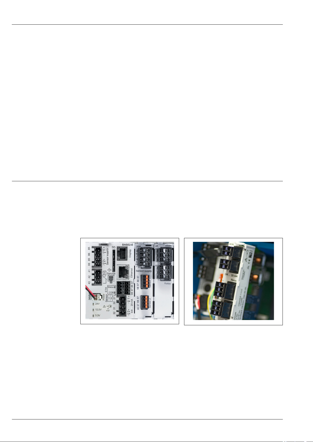
Electrical connection Basic module
13 Basic module BASE2-H or -L (two-channel
device)
1 Power supply for digital fixed cable sensors with
Memosens protocol
2 SD card slot
3
Slot for display cable
4 Ethernet interface
5 Connections for 2 Memosens sensors
6 Current outputs
7 Power connection
8 Service interface
9 Alarm relay connection
1)
For optional external display.
2)
Power supply to DIN rail power unit.
1)
A0040639
14 Basic module BASE2-E (four- and eight-
channel device)
1 Power supply for digital fixed cable sensors with
Memosens protocol
2 SD card slot
3
Slot for display cable
4 Ethernet interface
5 Connections for 2 Memosens sensors
6 Current outputs
7
Socket for internal supply cable
8 LEDs
9 Service interface
10 Alarm relay connection
1)
A0040640
2)
Endress+Hauser 29
Page 30

Connecting supply voltage for CM442R
N/- L/+PE
85
85
86
86
SD
Display
Sensor supply
+
+
–
Service
PK
GY
PK
GY
1
2
–
L
N
*
Power
L/+
N/–
PE
+
–
A
B
41
43
42
Alarm
31
31
32
32
0/4 ... 20 mA
+
+
–
–
HART
+
–
A
B
Sensor 2
Ethernet
87
88
97
98
87
88
97
98
BN
WH
GN
YE
BN
WH
GN
YE
Sensor 1
1
2
L N
+ RD
- BK
*
85
85
86
86
SD
Display
Sensor supply
+
+
–
Service
PK
GY
PK
GY
1
2
–
+
–
A
B
41
43
42
Alarm
31
31
32
32
0/4 ... 20 mA
+
+
–
–
HART
+
–
A
B
Sensor 2
Ethernet
87
88
97
98
87
88
97
98
BN
WH
GN
YE
BN
WH
GN
YE
Sensor 1
1
2
L/+
N/–
*
Power
L/+
N/–
PE
Power
(internal)
B
Liquiline CM442R/CM444R/CM448R
A0039665
15 Connecting power supply on the BASE2-H or -
L
H Power unit 100 to 230 VAC
L Power unit 24 VAC or 24 VDC
16 Overall wiring diagram for BASE2-H or -L
A0039625
Connecting supply voltage for CM444R and CM448R
30 Endress+Hauser
17 Connecting power supply with BASE2-E
* Assignment depending on power unit, make sure
to connect correctly
The two device versions may only be operated with the power unit supplied and the power unit
cable. Also pay attention to the information in the operating manual supplied for the power
unit.
A0039668
18 Overall wiring diagram for BASE2-E and
external power unit (B)
A0039624
Page 31

Liquiline CM442R/CM444R/CM448R
41
43
42
31
31
32
32
0/4 ... 20 mA
+
+
–
1
2
–
Relay
1
2
41
43
42
Relay
41
43
42
Relay 1
41
43
42
Relay 2
41
43
42
Relay 3
41
43
42
Relay 4
41
43
42
Relay 1
41
43
42
Relay 2
85
85
86
86
87
88
97
98
Sensor supply
+
+
–
PK
GY
PK
GYGY
1
2
–
BN
WH
GN
YE
+
–
A
B
87
88
97
98
BN
WH
GN
YE
+
–
A
B
Sensor 1
Sensor 2
47
47
48
48
+
+
–
1
2
–
1
2
1
2
+
–
–
+
+
–
+
–
45
46
45
46
91
92
91
92
Connecting optional modules
With extension modules you can purchase additional functions for your device.
NOTICE
Unacceptable hardware combinations (due to conflicts in power supply)
Incorrect measurements or total failure of the measuring point as a result of heat build-up or
overloading
If you are planning to extend your controller, make sure the resulting hardware combination is
‣
permitted (Configurator at www.endress.com/CM442R or .../CM444R or .../CM448R).
Remember that the sum of all current inputs and outputs may not exceed 8.
‣
Make sure not to use more than 2 "DIO" modules. More "DIO" modules are not permitted.
‣
Please contact your Endress+Hauser sales center should you have any questions.
‣
Overview of all the modules available
Module name
AOR 2R 4R 2DS DIO
• 2 x 0/4 to 20 mA
analog outputs
• 2 relays
• Order No.
71111053
Endress+Hauser 31
• 2 relays
• Order No.
71125375
• 4 relays
• Order No.
71125376
• 2 digital sensor
inputs
• 2 power supply
systems for digital
sensors
• Order No.
71135631
• 2 digital inputs
• 2 digital outputs
with auxiliary
voltage
• Order No.
71135638
Page 32

Liquiline CM442R/CM444R/CM448R
2324
2324
31
31
32
32
0/4 ... 20 mA
+
+
–
1
2
–
31
31
32
32
0/4 ... 20 mA
+
+
–
1
2
–
31
31
32
32
0/4 ... 20 mA
+
+
–
3
4
–
23
23
24
24
0/4 ... 20 mA
+
+
–
1
2
–
Ethernet
81
82
DIP switch
on
1
2
4
8
16
32
64
128/SW
Service
T
COM
SF
BF
PWR
DGND
VP
96'
95'
99'
Termination
DP/
RS485
96
95
99
Module name
2AO 4AO 2AI 485
• 2 x 0/4 to 20 mA
analog outputs
• Order No.
71135632
• 4 x 0/4 to 20 mA
analog outputs
• Order No.
71135633
• 2 x 0/4 to 20mA
analog inputs
• Order No.
71135639
• Ethernet (web
server or Modbus
TCP)
• 5V power supply
for PROFIBUS DP
termination
• RS485 (PROFIBUS
DP or Modbus
RS485)
• Use of BASE2
module disables
Ethernet port of
module 485
• Order No.
71135634
32 Endress+Hauser
PROFIBUS DP (module 485)
Contacts 95, 96 and 99 are bridged in the connector. This ensures that PROFIBUS
communication is not interrupted if the connector is disconnected.
Page 33

Liquiline CM442R/CM444R/CM448R
Protective ground connection
19 Mounting rail for functional ground connections
A0025366
Sensor connection
Sensors with Memosens protocol
Sensor types Sensor cable Sensors
Digital sensors without
additional internal power
supply
Digital sensors with
additional internal power
supply
With plug-in
connection and
inductive signal
transmission
Fixed cable Conductivity sensors with inductive measurement of
Fixed cable • Turbidity sensors
• pH sensors
• ORP sensors
• Combined sensors
• Oxygen sensors (amperometric and optical)
• Conductivity sensors with conductive measurement
of conductivity
• Chlorine sensors (disinfection)
conductivity
• Sensors for interface measurement
• Sensors for measuring the spectral absorption
coefficient (SAC)
• Nitrate sensors
• Optical oxygen sensors
• Ion-sensitive sensors
The following rule applies if connecting CUS71D sensors:
• CM442R
• Only one CUS71D is possible; an additional sensor is not permitted.
• The second sensor input may also not be used for another type of sensor.
• CM444R
No restrictions. All the sensor inputs can be used as required.
• CM448R
• If a CUS71D is connected, the number of sensor inputs that can be used is limited to a maximum
of 4.
• Of these, all 4 inputs can be used for CUS71D sensors.
• Every combination of CUS71D and other sensors is possible, provided that the total number of
connected sensors does not exceed 4.
Connection
Direct connection of the sensor cable to the terminal connector of the sensor module 2DS or of the
base module-L, -H or -E (→ 20 ff.)
Endress+Hauser 33
Page 34

Liquiline CM442R/CM444R/CM448R
98 97 88 87
86 85 86 85
BN
WH
GN
YE
Sensor
98 97 88 87
86 85 86 85
GN
YE
Sensor
PK
GY
85 86
85
2DS
1
2
86
97 88 8798
97 88 8798
Sensor 1
Sensor 2
PK
GY
GN
YE
BN
WH
GN
YE
Sensor
Sensor
20 sensors without additional supply voltage
22 sensors with and without additional supply
voltage at sensor module 2DS
A0039629
A0033206
A0039622
21 sensors with additional supply voltage
34 Endress+Hauser
Page 35

Liquiline CM442R/CM444R/CM448R
Performance characteristics
Response time
Reference temperature
Measured error for sensor inputs
Measured error for current inputs and outputs
Frequency tolerance of digital inputs and outputs
Resolution of current inputs and outputs
Current outputs
t90 = max. 500 ms for an increase from 0 to 20 mA
Current inputs
t90 = max. 330 ms for an increase from 0 to 20 mA
Digital inputs and outputs
t90 = max. 330 ms for an increase from low to high
25 °C (77 °F)
→ Documentation of the connected sensor
Typical measured errors:
< 20 µA (with current values < 4 mA)
< 50 µA (with current values 4 to 20 mA)
at 25 ˚C (77˚ F) each
Additional measured error depending on the temperature:
< 1.5 µA/K
≤ 1%
< 5 µA
Repeatability
Mounting on DIN rail as per IEC 60715
→ Documentation of the connected sensor
Installation
NOTICE
Incorrect mounting location in the cabinet, spacing regulations not observed
Possible malfunctions as a result of heat buildup and interference from neighboring devices!
Do not position the device directly above sources of heat. The temperature specification must be
‣
observed.
The components are designed for convection-based cooling. Avoid heat buildup. Ensure openings
‣
are not covered, e.g. by cables.
Observe the specified distances to other devices.
‣
Physically separate the device from frequency converters and high-voltage devices.
‣
Recommended installation direction: horizontal. The specified ambient conditions, and
‣
particularly the ambient temperatures, only apply for horizontal installation.
Vertical orientation is also possible. However, this requires additional fixing clips at the place of
‣
installation to hold the device in position on the DIN rail.
Recommended installation of power unit for CM444R and CM448R: to the left of the device.
‣
Endress+Hauser 35
Page 36

Liquiline CM442R/CM444R/CM448R
min. 50 (1.97)
min. 20 (0.79)
min. 50 (1.97)
min. 20 (0.79)
min. 50 (1.97)
83 (3.27) 205.5 (8.09)
75 (2.95)
75 (2.95)
100 (3.94)
100 (3.94)
4 x 4.5 (0.18)! 4 x 4.5 (0.18)!
The following minimum clearance specifications must be observed:
• Distances at the side in relation to other devices incl. power units and to the wall of the cabinet:
at least 20 mm (0.79 inch)
• Distance above and below the device and depth distance (to control cabinet door or other devices
installed there):
at least 50 mm (1.97 inch)
Wall mounting
A0039735
23 Minimum clearance in mm (in)
A0025370
24 Drilling pattern for wall mounting in mm (in)
36 Endress+Hauser
Page 37

Liquiline CM442R/CM444R/CM448R
4 x min. Ø 8 (0.31)
min. Ø 15 (0.59)
140 (5.51)
105 (4.13)
105 (4.13)
140 (5.51)
a
b
b
Mounting the external display
The mounting plate also serves as the drilling template. The marks on the side help you mark
the position of the drill holes.
A0025371
25 Mounting plate of external display, dimensions in mm (in)
a Retaining tab
b Production-related recesses, no function for the user
Ambient temperature range
Environment
CM442R
0 to 60 ˚C (32 to 140 ˚F)
CM444R
• Generally 0 to 55 ˚C (32 to 130 ˚F), with the exception of packages under the second list item
• 0 to 50 ˚C (32 to 120 ˚F) for the following packages:
• CM444R-**M40A7FI*+...
• CM444R-**M40A7FK*+...
• CM444R-**M4AA5F4*+...
• CM444R-**M4AA5FF*+...
• CM444R-**M4AA5FH*+...
• CM444R-**M4AA5FI*+...
• CM444R-**M4AA5FK*+...
• CM444R-**M4AA5FM*+...
• CM444R-**M4BA5F4*+...
• CM444R-**M4BA5FF*+...
• CM444R-**M4BA5FH*+...
• CM444R-**M4BA5FI*+...
• CM444R-**M4BA5FK*+...
• CM444R-**M4BA5FM*+...
• CM444R-**M4DA5F4*+...
• CM444R-**M4DA5FF*+...
• CM444R-**M4DA5FH*+...
• CM444R-**M4DA5FI*+...
• CM444R-**M4DA5FK*+...
• CM444R-**M4DA5FM*+...
Endress+Hauser 37
Page 38

Liquiline CM442R/CM444R/CM448R
CM448R
• Generally 0 to 55 ˚C (32 to 130 ˚F), with the exception of packages under the second list item
• 0 to 50 ˚C (32 to 120 ˚F) for the following packages:
• CM448R-***6AA*+...
• CM448R-***8A4*+...
• CM448R-***8A5*+...
• CM448R-**28A3*+...
• CM448R-**38A3*+...
• CM448R-**48A3*+...
• CM448R-**58A3*+...
• CM448R-**68A3*+...
• CM448R-**26A5*+...
• CM448R-**36A5*+...
• CM448R-**46A5*+...
• CM448R-**56A5*+...
• CM448R-**66A5*+...
• CM448R-**22A7*+...
• CM448R-**32A7*+...
• CM448R-**42A7*+...
• CM448R-**52A7*+...
• CM448R-**62A7*+...
• CM448R-**A6A5*+...
• CM448R-**A6A7*+...
• CM448R-**B6A5*+...
• CM448R-**B6A7*+...
• CM448R-**C6A5*+...
• CM448R-**C6A7*+...
• CM448R-**D6A5*+...
• CM448R-**D6A7*+...
External display (optional)
–20 to 60 ˚C (0 to 140 ˚F)
Storage temperature
Humidity
Degree of protection
Climate class
Vibration resistance
–25 to 85 °C (–13 to 185 °F)
DIN rail device
5 to 85%, not condensing
External display (in installed state)
5 to 95%, not condensing
DIN rail device
IP20 shock protection
External display
IP66 front-panel, when installed correctly including seal for housing door
As per IEC 60654-1: B2
Environmental tests
Vibration test based on DIN EN 60068-2, October 2008
Vibration test based on DIN EN 60654-3, August 1998
Wall mounting
Frequency range 10 to 150 Hz (sinusoidal)
Amplitude 10 to 12.9 Hz:
12.9 to 150 Hz:
0.75 mm
1)
0.5 g
Test duration 10 frequency cycles/ spatial axis, in 3 spatial axes (1 oct./min)
1)
g ... gravitational acceleration (1 g ≈ 9.81 m/s2)
Electromagnetic
Interference emission and interference immunity as per EN 61326-1:2013, Class A for Industry
compatibility
38 Endress+Hauser
Page 39

Liquiline CM442R/CM444R/CM448R
99 (3.90)
97 (3.82)
7.5 (0.30)
100 (3.94)
TS 35
114 (4.49)
89 (3.50)
91 (3.58)
TS 35
75 (2.95)
83 (3.27)
Electrical safety
Degree of contamination DIN rail device
IEC 61010-1, Class I equipment
Low voltage: overvoltage category II
Environment < 2000 m (< 6562 ft) above MSL
The product is suitable for pollution degree 2.
Optional display
The product is suitable for pollution degree 4.
Mechanical construction
Dimensions CM442R
26 Dimensions in mm (inch)
Endress+Hauser 39
A0039729
Page 40

CM444R and CM448R
220 (8.66)
97 (3.82)
7.5 (0.30)
100 (3.94)
75 (2.95)
205.5 (8.09)
114 (4.49)
TS 35
TS 35
89 (3.50)
91 (3.58)
Liquiline CM442R/CM444R/CM448R
27 Dimensions in mm (inch)
A0039730
40 Endress+Hauser
Page 41

Liquiline CM442R/CM444R/CM448R
144 (5.67)
144 (5.67)
39.5 (1.56)
54 (2.13)
125 (4.92)
121 (4.76)
32 (1.26)
40 (1.58) 99 (3.99)
90 (3.54)
out
in
75 (2.95)
45 (1.77) 100 (3.94)
32 (1.26)
102 (4.02)
124 (4.88)
Optional display
28 Dimensions in mm (inch)
External power units (CM444R and CM448R only)
Depending on the version ordered, a power unit for connection to 230 V or 24 V is supplied. There
are two delivery variants for each version (cannot be selected). The factory-preferred variant is
shown on the left in each case.
A0025738
29 Power unit 230 V
30 Power unit 230 V (optional)
A0025346
A0025739
Endress+Hauser 41
31 Power unit 24 V
A0025784
32 Power unit 24 V (optional)
A0025786
Page 42

Liquiline CM442R/CM444R/CM448R
A A
B
B
B-B
A-A
193 (7.60)
123 (4.84)
157 (6.18)
119 (4.69)
R16
13.5 (0.53)
36 (1.42)
143 (5.63)
40 (1.57)
47 (1.85)
144.5 (5.69)
Service display (accessories)
The service display comprises:
• Portable display (same dimensions as under "Optional display")
• Cover to protect the display and to hook it onto the (open) cabinet door
Weight
Materials
A0025343
33 Dimensions of the service display cover in mm (inch)
depending on the version:
CM442R (fully configured) Approx. 0.45 kg (1 lbs)
CM444R and CM448R (fully configured) Approx. 0.95 kg (2.1 lbs)
Individual module Approx. 0.06 kg (0.13 lbs)
External display (excluding cables) Approx. 0.56 kg (1.2 lbs)
Service display cover 0.46 kg (1 lbs)
External power unit (CM444R, CM448R) 0.27 to 0.42 kg (0.60 to 0.92 lbs), depending on the power
unit variant
DIN rail housing PC-FR
Display cover PC-FR
Display seal EPDM
Soft keys EPDM
Module covers PBT GF30 FR
Terminal strip Nickel-plated brass
Ground terminals Stainless steel 1.4301 (AISI304)
Threaded fasteners Stainless steel 1.4301 (AISI304)
Mounting plate (optional display) Stainless steel 1.4301 (AISI304)
Securing screws (optional display) Steel, galvanized
Cover for service display (accessories) EPDM
42 Endress+Hauser
Page 43

Liquiline CM442R/CM444R/CM448R
Outlet 1
MENU
CH 1:1 pH
CH 1:1 Temperature
CH 1:2 Nitrate
CH 2:1 SAC
CH 2:2 Turbidity
CH 3:1 Current Input [Flow]
6.99 pH
25.1 °C
9.02 mg/l
2.02 1/m
1022 FNU
15.1 nA
11:09:15 29.01.2013
1
2
3
Operability
External display
Operating concept
Graphic display:
• Resolution: 240 x 160 pixel
• Back light with switch-off function
• Red display background for alarms alerts users to errors
• Transflective display technology for maximum contrast even in bright environments
• User-definable measuring menus mean you can always keep track of the values that are important
for your application.
The simple and structured operating concept sets new standards:
• Intuitive operation with the navigator and soft keys
• Fast configuration of application-specific measurement options
• Easy configuration and diagnosis thanks to plain-text display
• All languages that can be ordered are available in every device
A0025229
34 Operation via external, optional display
35 Plain-text menu
Local operation via external, optional display
A0025231
36 Overview of operation
1 Display (with red display background in alarm condition)
2 Soft keys (function depends on menu)
3 Navigator (jog/shuttle and press/hold function)
Endress+Hauser 43
Page 44

Remote operation Via HART (e.g. via HART modem and FieldCare)
1
3
2
USB
31
32
250 ... 500 Ω
FXA291
Master class 1
(PLC, DCS)
T T
Ethernet
PROFIBUS DP
(RS485)
Master class 2 (FieldCare, PDM)
37 HART using modem
1 Device module Base2-L, -H or -E: current output 1 with HART
2
HART modem for connection to PC, e.g. Commubox FXA191 (RS232) or FXA195 1) (USB)
3 HART handheld terminal
1)
Switch position "on" (substitutes the resistor)
Liquiline CM442R/CM444R/CM448R
A0039620
Via PROFIBUS DP
A0039617
38 PROFIBUS DP
T Terminating resistor
44 Endress+Hauser
Page 45

Liquiline CM442R/CM444R/CM448R
FXA291
Ethernet
Modbus Master / Gateway
T T
Modbus RS485
(RTU, ASCII)
FieldCare/
Webbrowser
FXA291
Ethernet
Ethernet client
Via Modbus RS485
39 Modbus RS485
T Terminating resistor
A0039615
Via Ethernet: web server/Modbus TCP/PROFINET/EtherNet/IP
40 Modbus TCP or EtherNet/IP or PROFINET
Language packages
The language selected in the product structure is the operating language preset at the factory. All
other languages can be selected using the menu.
• English (US)
• German
• Chinese (Simplified, PR China)
• Czech
• Dutch
• French
• Italian
• Japanese
• Polish
• Portuguese
• Russian
• Spanish
• Swedish
• Turkish
A0039616
Endress+Hauser 45
Page 46

Liquiline CM442R/CM444R/CM448R
• Hungarian
• Croatian
• Vietnamese
The availability of other languages can be checked via the product structure at www.endress.com/
cm442R or .../cm444R or .../cm448R.
Certificates and approvals
mark
EAC
cCSAus
The product meets the requirements of the harmonized European standards. As such, it complies
with the legal specifications of the EU directives. The manufacturer confirms successful testing of the
product by affixing to it the mark.
The product has been certified according to guidelines TP TC 004/2011 and TP TC 020/2011 which
apply in the European Economic Area (EEA). The EAC conformity mark is affixed to the product.
The device has been certified with regard to its electrical safety and for NI Class I Div. 2 cCSAus
explosion-proof environments. It meets the requirements in accordance with:
• CLASS 2252 06 - Process Control Equipment
• CLASS 2252 86 - Process Control Equipment - Certified to US Standards
• CLASS 2258 03 - Process Control Equipment - Intrinsically Safe and Non-incendive Systems - For
Hazardous Locations
• CLASS 2258 83 - Process Control Equipment - Intrinsically Safe and Non-incendive Systems - For
Hazardous Locations - Certified to US Standards
• FM3600
• FM3611
• FM3810
• UL50E
• IEC 60529
• CAN/CSA-C22.2 No. 0
• CAN/CSA C22.2 No. 94
• CSA Std. C22.2 No. 213
• CAN/CSA-C22.2 No. 61010-1
• CAN/CSA-C22.2 No. 60529
• UL/ANSI/ISA 61010-1
• ANSI - ISA 12 12 01
Marine approvals
Product page
Product Configurator
The device must be installed in a housing or cabinet where access is only possible with a tool or
‣
key.
A selection of the devices and sensors have type approval for marine applications, issued by the
following classification societies: ABS (American Bureau of Shipping), BV (Bureau Veritas), DNV-GL
(Det Norske Veritas-Germanischer Lloyd) and LR (Lloyd’s Register). Details of the order codes of the
approved devices and sensors, and the installation and ambient conditions, are provided in the
relevant certificates for marine applications on the product page on the Internet.
Ordering information
www.endress.com/cm442r
www.endress.com/cm444r
www.endress.com/cm448r
On the product page there is a Configure button to the right of the product image.
1. Click this button.
The Configurator opens in a separate window.
46 Endress+Hauser
Page 47

Liquiline CM442R/CM444R/CM448R
2. Select all the options to configure the device in line with your requirements.
In this way, you receive a valid and complete order code for the device.
3. Export the order code as a PDF or Excel file. To do so, click the appropriate button on the right
above the selection window.
For many products you also have the option of downloading CAD or 2D drawings of the
selected product version. Click the CAD tab for this and select the desired file type using
picklists.
Scope of delivery
Measuring cable
The scope of delivery comprises:
• 1 multichannel controller in the version ordered
• 1 mounting plate
• 1 external display (if selected as an option)
• 1 DIN rail power unit incl. Cable (CM444R and CM448R only)
• 1 printed copy of the Operating Instructions for DIN rail power unit
• 1 printed copy of the Brief Operating Instructions in the language ordered
2)
Accessories
The following are the most important accessories available at the time this documentation was
issued.
For accessories not listed here, please contact your Service or Sales Center.
‣
Memosens data cable CYK10
• For digital sensors with Memosens technology
• Product Configurator on the product page: www.endress.com/cyk10
Technical Information TI00118C
Memosens data cable CYK11
• Extension cable for digital sensors with Memosens protocol
• Product Configurator on the product page: www.endress.com/cyk11
Technical Information TI00118C
Sensors Glass electrodes
Orbisint CPS11D
• pH sensor for process technology
• Optional SIL version for connecting to SIL transmitter
• With dirt-repellent PTFE diaphragm
• Product Configurator on the product page: www.endress.com/cps11d
Technical Information TI00028C
Memosens CPS31D
• pH electrode with gel-filled reference system with ceramic diaphragm
• Product Configurator on the product page: www.endress.com/cps31d
Technical Information TI00030C
Ceraliquid CPS41D
• pH electrode with ceramic junction and KCl liquid electrolyte
• Product Configurator on the product page: www.endress.com/cps41d
Technical Information TI00079C
2) The external display can be selected as an option in the order structure or ordered as an accessory at a later stage.
Endress+Hauser 47
Page 48

Liquiline CM442R/CM444R/CM448R
Ceragel CPS71D
• pH electrode with reference system including ion trap
• Product Configurator on the product page: www.endress.com/cps71d
Technical Information TI00245C
Memosens CPS171D
• pH electrode for bio-fermenters with digital Memosens technology
• Product Configurator on the product page: www.endress.com/cps171d
Technical Information TI01254C
Orbipore CPS91D
• pH electrode with open aperture for media with high dirt load
• Product Configurator on the product page: www.endress.com/cps91d
Technical Information TI00375C
Orbipac CPF81D
• Compact pH sensor for installation or immersion operation
• In industrial water and wastewater
• Product Configurator on the product page: www.endress.com/cpf81d
Technical Information TI00191C
Enamel pH electrodes
Ceramax CPS341D
• pH electrode with pH-sensitive enamel
• Meets highest demands of measuring accuracy, pressure, temperature, sterility and durability
• Product Configurator on the product page: www.endress.com/cps341d
Technical Information TI00468C
ORP sensors
Orbisint CPS12D
• ORP sensor for process technology
• Product Configurator on the product page: www.endress.com/cps12d
Technical Information TI00367C
Ceraliquid CPS42D
• ORP electrode with ceramic junction and KCl liquid electrolyte
• Product Configurator on the product page: www.endress.com/cps42d
Technical Information TI00373C
Ceragel CPS72D
• ORP electrode with reference system including ion trap
• Product Configurator on the product page: www.endress.com/cps72d
Technical Information TI00374C
Orbipac CPF82D
• Compact ORP sensor for installation or immersion operation in process water and wastewater
• Product Configurator on the product page: www.endress.com/cpf82d
Technical Information TI00191C
Orbipore CPS92D
• ORP electrode with open aperture for media with high dirt load
• Product Configurator on the product page: www.endress.com/cps92d
Technical Information TI00435C
48 Endress+Hauser
Page 49

Liquiline CM442R/CM444R/CM448R
pH ISFET sensors
Tophit CPS441D
• Sterilizable ISFET sensor for low-conductivity media
• Liquid KCl electrolyte
• Product Configurator on the product page: www.endress.com/cps441d
Technical Information TI00352C
Tophit CPS471D
• Sterilizable and autoclavable ISFET sensor for food and pharmaceutics, process engineering
• Water treatment and biotechnology
• Product Configurator on the product page: www.endress.com/cps471d
Technical Information TI00283C
Tophit CPS491D
• ISFET sensor with open aperture for media with high dirt load
• Product Configurator on the product page: www.endress.com/cps491d
Technical Information TI00377C
pH and ORP combined sensors
Memosens CPS16D
• Combined pH/ORP sensor for process technology
• With dirt-repellent PTFE diaphragm
• With Memosens technology
• Product Configurator on the product page: www.endress.com/cps16D
Technical Information TI00503C
Memosens CPS76D
• Combined pH/ORP sensor for process technology
• Hygienic and sterile applications
• With Memosens technology
• Product Configurator on the product page: www.endress.com/cps76d
Technical Information TI00506C
Memosens CPS96D
• Combined pH/ORP sensor for chemical processes
• With poison-resistant reference with ion trap
• With Memosens technology
• Product Configurator on the product page: www.endress.com/cps96d
Technical Information TI00507C
Conductivity sensors with inductive measurement of conductivity
Indumax CLS50D
• High-durability inductive conductivity sensor
• For standard and hazardous area applications
• With Memosens technology
• Product Configurator on the product page: www.endress.com/cls50d
Technical Information TI00182C
Indumax H CLS54D
• Inductive conductivity sensor
• With certified, hygienic design for foodstuffs, beverages, pharmaceuticals and biotechnology
• Product Configurator on the product page: www.endress.com/cls54d
Technical Information TI00508C
Endress+Hauser 49
Page 50

Liquiline CM442R/CM444R/CM448R
Conductivity sensors with conductive measurement of conductivity
Condumax CLS15D
• Conductive conductivity sensor
• For pure water, ultrapure water and hazardous area applications
• Product Configurator on the product page: www.endress.com/CLS15d
Technical Information TI00109C
Condumax CLS16D
• Hygienic, conductive conductivity sensor
• For pure water, ultrapure water and Ex applications
• With EHEDG and 3A approval
• Product Configurator on the product page: www.endress.com/CLS16d
Technical Information TI00227C
Condumax CLS21D
• Two-electrode sensor in plug-in head version version
• Product Configurator on the product page: www.endress.com/CLS21d
Technical Information TI00085C
Memosens CLS82D
• Four-electrode sensor
• With Memosens technology
• Product Configurator on the product page: www.endress.com/cls82d
Technical Information TI01188C
Oxygen sensors
Oxymax COS22D
• Sterilizable sensor for dissolved oxygen
• With Memosens technology or as an analog sensor
• Product Configurator on the product page: www.endress.com/cos22d
Technical Information TI00446C
Oxymax COS51D
• Amperometric sensor for dissolved oxygen
• With Memosens technology
• Product Configurator on the product page: www.endress.com/cos51d
Technical Information TI00413C
Oxymax COS61D
• Optical oxygen sensor for drinking water and industrial water measurement
• Measuring principle: quenching
• With Memosens technology
• Product Configurator on the product page: www.endress.com/cos61d
Technical Information TI00387C
Memosens COS81D
• Sterilizable, optical sensor for dissolved oxygen
• With Memosens technology
• Product Configurator on the product page: www.endress.com/cos81d
Technical Information TI01201C
50 Endress+Hauser
Page 51

Liquiline CM442R/CM444R/CM448R
Disinfection sensors
CCS142D
• Membrane-covered amperometric sensor for free chlorine
• Measuring range 0.01 to 20 mg/l
• With Memosens technology
• Product Configurator on the product page: www.endress.com/ccs142d
Technical Information TI00419C
Ion-selective sensors
ISEmax CAS40D
• Ion selective sensors
• Product Configurator on the product page: www.endress.com/cas40d
Technical Information TI00491C
Turbidity sensors
Turbimax CUS51D
• For nephelometric measurements of turbidity and solids in wastewater
• 4-beam scattered light method
• With Memosens technology
• Product Configurator on the product page: www.endress.com/cus51d
Technical Information TI00461C
Turbimax CUS52D
• Hygienic Memosens sensor for turbidity measurement in drinking water, process water and in
utilities
• With Memosens technology
• Product Configurator on the product page: www.endress.com/cus52d
Technical Information TI01136C
SAC and nitrate sensors
Viomax CAS51D
• SAC and nitrate measurement in drinking water and wastewater
• With Memosens technology
• Product Configurator on the product page: www.endress.com/cas51d
Technical Information TI00459C
Interface measurement
Turbimax CUS71D
• Immersion sensor for interface measurement
• Ultrasonic interface sensor
• Product Configurator on the product page: www.endress.com/cus71d
Technical Information TI00490C
Additional functionality Hardware extension modules
Kit, extension module AOR
• 2 x relay, 2 x 0/4 to 20 mA analog output
• Order No. 71111053
Kit, extension module 2R
• 2 x relay
• Order No. 71125375
Kit, extension module 4R
• 4 x relay
• Order No. 71125376
Endress+Hauser 51
Page 52

Liquiline CM442R/CM444R/CM448R
Kit, extension module 2AO
• 2 x 0/4 to 20 mA analog output
• Order No. 71135632
Kit, extension module 4AO
• 4 x analog output 0/4 to 20 mA
• Order No. 71135633
Kit, extension module 2DS
• 2 x digital sensor, Memosens
• Order No. 71135631
Kit, extension module 2AI
• 2 x 0/4 to 20 mA analog input
• Order No. 71135639
Kit, extension module DIO
• 2 x digital input
• 2 x digital output
• Auxiliary voltage supply for digital output
• Order No. 71135638
Kit, extension module 485
• Can be extended to PROFIBUS DP or Modbus RS485. This requires an additional activation code
which can be ordered separately.
• Order No. 71135634
Upgrade kit, extension module 485 with PROFIBUS DP
• Extension module 485
• PROFIBUS DP (+ Ethernet configuration)
• Order No. 71140888
Upgrade kit, extension module 485 with Modbus RS485
• Extension module 485
• Modbus RS485 (+ Ethernet configuration)
• Order No. 71140889
Firmware and activation codes
SD card with Liquiline firmware
• Industrial Flash Drive, 1 GB
• Order No. 71127100
You must quote the serial number of the device when ordering the activation code.
Activation code for digital HART communication
Order No. 71128428
Activation code for PROFIBUS DP
Order No. 71135635
Activation code for Modbus RS485
Order No. 71135636
Activation code for PROFINET + web server for BASE2
Order No. 71449901
Activation code for Ethernet/IP + web server for BASE2
Order No. 71449914
Activation code for Modbus TCP + web server for BASE2
Order No. 71449915
Activation code for web server for BASE2
Order No. 71449918
Kit CM442R: activation code for 2nd digital sensor input
Order No. 71114663
Kit CM444R/CM448R: upgrade code for 2 x 0/4 to 20 mA for BASE2-E
On request
Activation code for feedforward control
• Requires current input or fieldbus communication
• Order No. 71211288
52 Endress+Hauser
Page 53

Liquiline CM442R/CM444R/CM448R
Activation code for measuring range switch
• Requires digital inputs or fieldbus communication
• Order No. 71211289
Activation code for ChemocleanPlus
• Requires relays or digital outputs or fieldbus communication and optional digital inputs
• Order No. 71239104
Activation code for Heartbeat Verification and Monitoring
Order No. 71367524
Activation code for ion exchanger operating time
• Configure the mathematical function
• Order No. 71367531
Activation code for mathematics
• Formula editor
• Order No. 71367541
Software
Other accessories
Memobase Plus CYZ71D
• PC software to support laboratory calibration
• Visualization and documentation of sensor management
• Sensor calibrations stored in database
• Product Configurator on the product page: www.endress.com/cyz71d
Technical Information TI00502C
Field Data Manager Software MS20
• PC software for central data management
• Visualization of series of measurements and logbook events
• SQL database for secure data storage
FieldCare SFE500
• Universal tool for field device configuration and management
• Supplied with a complete library of certified DTMs (Device Type Manager) for operation of Endress
+Hauser field devices
• Order according to product order structure
• www.endress.com/sfe500
External display
3)
Graphic display
• For installation in the control cabinet door or panel
• Order No. 71185295
Service display
• Portable, for commissioning
• Order No. 71185296
SD card
• Industrial Flash Drive, 1 GB
• Order No. 71110815
Communication-specific accessories
Commubox FXA195
Intrinsically safe HART communication with FieldCare via the USB port
Technical Information TI00404F
Commubox FXA291
Connects the CDI interface of measuring devices with the USB port of the computer or laptop
Technical Information TI00405C
3) The external display can be selected as an option in the product structure or ordered subsequently as an accessory.
Endress+Hauser 53
Page 54

Liquiline CM442R/CM444R/CM448R
Wireless HART adapter SWA70
• Wireless device connection
• Easily integrated, offers data protection and transmission safety, can be operated in parallel with
other wireless networks, minimum cabling complexity
Technical Information TI00061S
System components
RIA14, RIA16
• Field display unit for integration into 4-20 mA circuits
• RIA14 in flameproof metal enclosure
Technical Information TI00143R and TI00144R
RIA15
• Process display unit, Digital display unit for integration into 4-20 mA circuits
• Panel mounting
• With optional HART communication
Technical Information TI01043K
54 Endress+Hauser
Page 55

Page 56

www.addresses.endress.com
 Loading...