

Page 1
BA00508C/07/EN/03.17
71377418
Products Solutions Services
Operating Instructions
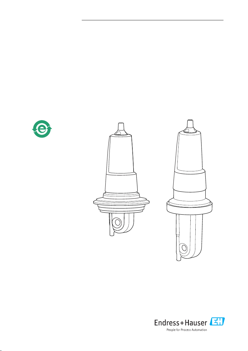
Indumax CLS54D
Conductivity sensor with inductive measurement of
conductivity and hygienic design for applications in
the food, beverage and pharmaceutical industries
and in biotechnology
Page 2

Page 3

Indumax CLS54D Table of contents
Table of contents
1 Document information ......... 4
1.1 Warnings ........................... 4
1.2 Symbols used ........................ 4
1.3 Symbols on the device ................ 5
2 Basic safety instructions ....... 6
2.1 Requirements for the personnel ........ 6
2.2 Designated use ...................... 6
2.3 Occupational safety .................. 6
2.4 Operational safety ................... 7
2.5 Product safety ....................... 7
3 Incoming acceptance and
product identification .......... 8
3.1 Incoming acceptance ................. 8
3.2 Scope of delivery ..................... 8
3.3 Product identification ................. 9
3.4 Certificates and approvals ............ 10
4 Installation .................... 11
4.1 Installation conditions ............... 11
4.2 Installation ........................ 13
4.3 Post-installation check ............... 13
5 Electrical connection .......... 14
5.1 Connecting to the transmitter ......... 14
5.2 Ensuring the degree of protection ..... 15
5.3 Post-connection check ............... 15
6 Maintenance .................. 16
7 Repairs ......................... 16
7.1 Return ............................ 16
7.2 Disposal ........................... 16
8 Accessories .................... 17
8.1 Cable extension ..................... 17
8.2 Calibration solutions ................ 17
9 Technical data ................. 18
Index ................................. 21
Endress+Hauser 3
Page 4
Document information Indumax CLS54D
1 Document information
1.1 Warnings
Structure of information Meaning
DANGER
L
Causes (/consequences)
If necessary, Consequences of noncompliance (if applicable)
Corrective action
‣
WARNING
L
Causes (/consequences)
If necessary, Consequences of noncompliance (if applicable)
Corrective action
‣
CAUTION
L
Causes (/consequences)
If necessary, Consequences of noncompliance (if applicable)
Corrective action
‣
NOTICE
Cause/situation
If necessary, Consequences of noncompliance (if applicable)
Action/note
‣
This symbol alerts you to a dangerous situation.
Failure to avoid the dangerous situation will result in a fatal or serious injury.
This symbol alerts you to a dangerous situation.
Failure to avoid the dangerous situation can result in a fatal or serious injury.
This symbol alerts you to a dangerous situation.
Failure to avoid this situation can result in minor or more serious injuries.
This symbol alerts you to situations which may result in damage to property.
1.2 Symbols used
Symbol Meaning
Additional information, tips
Permitted or recommended
Not permitted or not recommended
Reference to device documentation
Reference to page
Reference to graphic
Result of a step
4 Endress+Hauser
Page 5
Indumax CLS54D Document information
1.3 Symbols on the device
Symbol Meaning
Reference to device documentation
Endress+Hauser 5
Page 6

Basic safety instructions Indumax CLS54D
2 Basic safety instructions
2.1 Requirements for the personnel
• Installation, commissioning, operation and maintenance of the measuring system may be
carried out only by specially trained technical personnel.
• The technical personnel must be authorized by the plant operator to carry out the specified
activities.
• The electrical connection may be performed only by an electrical technician.
• The technical personnel must have read and understood these Operating Instructions and
must follow the instructions contained therein.
• Faults at the measuring point may only be rectified by authorized and specially trained
personnel.
Repairs not described in the Operating Instructions provided must be carried out only
directly at the manufacturer's site or by the service organization.
2.2 Designated use
Indumax CLS54D is designed for the inductive measurement of the conductivity of liquids in
the food and beverages industry.
The six-decade measuring range and the excellent chemical resistance properties of the
materials in contact with the medium make it possible to use this sensor in a wide range of
applications, such as:
• Concentration measurement of acids and bases
• Phase separation of products
The sensor is used with Liquiline CM44x/R/P, Liquiline CM42 or Liquiline CM14.
Use of the device for any purpose other than that described, poses a threat to the safety of
people and of the entire measuring system and is therefore not permitted.
The manufacturer is not liable for damage caused by improper or non-designated use.
NOTICE
Non-designated use
Incorrect measurements, malfunctions and even measuring point failure could result
Only use the product in accordance with the product specifications.
‣
Pay particular attention to the technical data on the nameplate.
‣
2.3 Occupational safety
As the user, you are responsible for complying with the following safety conditions:
• Installation guidelines
• Local standards and regulations
Electromagnetic compatibility
• The product has been tested for electromagnetic compatibility in accordance with the
applicable European standards for industrial applications.
• The electromagnetic compatibility indicated applies only to a product that has been
connected in accordance with these Operating Instructions.
6 Endress+Hauser
Page 7

Indumax CLS54D Basic safety instructions
2.4 Operational safety
1. Before commissioning the entire measuring point, verify that all connections are
correct. Ensure that electrical cables and hose connections are undamaged.
2. Do not operate damaged products, and safeguard them to ensure that they are not
operated inadvertently. Label the damaged product as defective.
3. If faults cannot be rectified:
Take the products out of operation and safeguard them to ensure that they are not
operated inadvertently.
2.5 Product safety
The product is designed to meet state-of-the-art safety requirements, has been tested, and
left the factory in a condition in which it is safe to operate. The relevant regulations and
European standards have been observed.
Endress+Hauser 7
Page 8

Incoming acceptance and product identification Indumax CLS54D
3 Incoming acceptance and product identification
3.1 Incoming acceptance
1. Verify that the packaging is undamaged.
Notify your supplier of any damage to the packaging.
Keep the damaged packaging until the matter has been settled.
2. Verify that the contents are undamaged.
Notify your supplier of any damage to the delivery contents.
Keep the damaged products until the matter has been settled.
3. Check the delivery for completeness.
Check it against the delivery papers and your order.
4. Pack the product for storage and transportation in such a way that it is protected
against impact and moisture.
The original packaging offers the best protection.
The permitted ambient conditions must be observed (see "Technical data").
If you have any questions, please contact your supplier or your local sales center.
3.2 Scope of delivery
The scope of delivery includes:
• Sensor in the version ordered
• Operating Instructions
8 Endress+Hauser
Page 9

Indumax CLS54D Incoming acceptance and product identification
3.3 Product identification
3.3.1 Nameplate
The nameplate can be found on the sensor.
The following information is provided on the nameplate:
• Manufacturer identification
• Order code
• Extended order code
• Serial number
• Cell constant (nominal value)
• Protection class
• Pressure specification at 20 °C
• Continuous service temperature
Compare the data on the nameplate with your order.
3.3.2 Product identification
Product page
www.endress.com/cls54D
Interpreting the order code
The order code and serial number of your product can be found in the following locations:
• On the nameplate
• In the delivery papers
Obtaining information on the product
1. Go to the product page for your product on the Internet.
2. At the bottom of the page, click the link Online Tools and then select Access device
specific information.
An additional window opens.
3. Enter the order code from the nameplate into the search field and then select Show
details.
You will receive information on each feature (selected option) of the order code.
Manufacturer's address
Endress+Hauser Conducta GmbH+Co. KG
Dieselstraße 24
D-70839 Gerlingen
Endress+Hauser 9
Page 10

Incoming acceptance and product identification Indumax CLS54D
3.4 Certificates and approvals
3.4.1 Hygiene
FDA
All materials in contact with the product are listed by the FDA.
EHEDG
Certified cleanability according to EHEDG TYPE EL-class I.
When using the sensor in hygienic applications, please note that the cleanability of the
sensor also depends on the way the sensor is installed. To install the sensor in a pipe, use
the appropriate and EHEDG-certified flow vessels for the particular process connection.
3-A
Certified according to 3-A Standard 74- ("3-A Sanitary Standards for Sensor and Sensor
Fittings and Connections Used on Milk and Milk Products Equipment").
Biological reactivity (USP class VI) (option)
Biological reactivity test certificate (Certificate of Compliance) according to USP (United States
Pharmacopoeia) part<87> and part <88> class VI with lot number traceability of materials in
contact with the medium.
3.4.2 mark
The product meets the requirements of the harmonized European standards. As such, it
complies with the legal specifications of the EU directives. The manufacturer confirms
successful testing of the product by affixing to it the mark.
10 Endress+Hauser
Page 11

Indumax CLS54D Installation
> 1 m (3.3 ft)
4 Installation
4.1 Installation conditions
4.1.1 Orientation
The sensor must be completely immersed in the medium. Avoid air bubbles in the area of the
sensor.
A0017691
1 Installation positions of the conductivity sensor
If the flow direction changes (after pipe bends), turbulence in the medium can result.
Install the sensor at a distance of at least 1 m (3.3 ft) downstream from a pipe bend.
The product should flow along the hole of the sensor (see the arrows on the housing). The
symmetrical measuring channel allows flow in both directions.
For a 3-A compliant installation, the following must be noted:
After the instrument is installed its hygienic integrity shall be maintained. All process
connections must be 3-A compliant.
Endress+Hauser 11
Page 12

Installation Indumax CLS54D
a
1
2
a[inch]
0
5
10 15
20
2525
a[mm]
0.80
1.00
1.20
1.40
f
0.20
0.39
0.59
0.79
0.98
4.1.2 Installation factor
The ionic current in the liquid is affected by the walls in
confined installation conditions. This effect is compensated
by what is referred to as the installation factor. The
installation factor can be entered in the transmitter for the
measurement or the cell constant is corrected by multiplying
by the installation factor.
The value of the installation factor depends on the diameter
and the conductivity of the pipe nozzle as well as the
distance a between the sensor and the wall.
The installation factor f (f = 1.00) can be disregarded if the
distance to the wall is sufficient (a > 15 mm, from DN 65).
If the distance to the wall is smaller, the installation factor
increases for electrically insulating pipes (f > 1), and
decreases for electrically conductive pipes (f < 1).
It can be measured using calibration solutions, or a close
approximation can be determined from the diagram below.
2 Installation of CLS54D
a Wall distance
A0005453
3 Relationship between installation factor f and wall distance a
1 Electrically conductive pipe wall
2 Electrically insulating pipe wall
4.1.3 Air set
The digital sensor has already been adjusted at the factory. Onsite compensation is not
required.
12 Endress+Hauser
A0005441
Page 13

Indumax CLS54D Installation
a
1
4.2 Installation
A0032586
4 Installed length of the sensor
1 Direction of medium flow
a Distance from pipe wall
When installing, align the sensor in such a way that the medium flows through the flow
‣
opening of the sensor in the direction of medium flow. The sensor head must be completely
immersed in the medium.
4.3 Post-installation check
Put the sensor into operation only if you can answer "yes" to the following questions:
• Are the sensor and cable undamaged?
• Is the orientation correct?
• Has the sensor been installed in the process connection, and does not suspend freely from
the cable?
Endress+Hauser 13
Page 14

Electrical connection Indumax CLS54D
2
A
B
20 (0.79)
20 (0.79)
PK
85
GY
86
BN
87
WH
88
GN
97
YE
98
63 (2.48)
75 (2.95)
80 (3.15)
1
5 Electrical connection
WARNING
L
Device is live
Incorrect connection may result in injury or death
The electrical connection may be performed only by an electrical technician.
‣
The electrical technician must have read and understood these Operating Instructions and
‣
must follow the instructions contained therein.
Prior to commencing connection work, ensure that no voltage is present on any cable.
‣
5.1 Connecting to the transmitter
The sensor is supplied with a fixed cable. The wiring diagram is provided in the Operating
Instructions of the transmitter used.
Connection via a junction box is necessary for a cable connection. The extension to the
transmitter is via the CYK11 cable.
5 Connection with CYK11 cable extension via junction box, dimensions in mm (inch)
1 Cable glands - shield fixed in gland
2 Shielding
A CYK11 from transmitter
B Sensor cable
Sensors with a fixed cable and M12 plug can be extended with the CYK11 measuring cable
and an M12 socket.
14 Endress+Hauser
A0032587
Page 15

Indumax CLS54D Electrical connection
A0017842
6 CYK11 for extension with M12 connection
1 Transmitter
2 CYK11 measuring cable with M12 connection
A CLS54D connecting cable with M12 plug
B Sensor CLS54D
5.2 Ensuring the degree of protection
Only the mechanical and electrical connections which are described in these instructions and
which are necessary for the required, designated use, may be carried out on the device
delivered.
Exercise care when carrying out the work.
‣
Otherwise, the individual types of protection (Ingress Protection (IP), electrical safety, EMC
interference immunity) agreed for this product can no longer be guaranteed due, for example,
to covers being left off or cable (ends) which are loose or insufficiently secured.
5.3 Post-connection check
Device condition and specifications Notes
Are the outside of the sensor, assembly, cable undamaged? Visual inspection
Electrical connection Notes
Are the installed cables strain-relieved and not twisted?
Is a sufficient length of the cable cores stripped, and is it positioned
in the terminal correctly?
Are all the screws terminals properly tightened? Tighten
Are all cable entries mounted, tightened and leak-tight? For lateral cable entries, make sure the cables
Are all cable entries installed downwards or mounted laterally?
Endress+Hauser 15
Check the fit (by pulling gently)
loop downwards to allow water to drip off
Page 16

Maintenance Indumax CLS54D
6 Maintenance
CAUTION
L
Corrosive chemicals
Danger of chemical burns to the eyes and skin. Danger of damage to clothing and equipment
It is absolutely essential to protect the eyes and hands properly when working with acids,
‣
bases and organic solvents!
Wear protective goggles and safety gloves.
‣
Clean away splashes on clothes and other objects to prevent any damage.
‣
Pay particular attention to the information provided in the safety data sheets for the
‣
chemicals used.
As there is no galvanic contact with the medium, inductive sensors are considerably less
sensitive to dirt and fouling than conventional conductive sensors.
However, dirt can clog the measuring channel which, in turn, can alter the cell constant. In
such cases, an inductive sensor also needs to be cleaned.
Clean away fouling on the sensor as follows depending on the type of fouling:
• Oily and greasy films:
Clean with grease remover, e.g. alcohol, acetone, possibly hot water and dishwashing
detergent.
• Lime and metal hydroxide buildup:
Dissolve buildup with diluted hydrochloric acid (3 %) and then rinse thoroughly with plenty
of clear water.
• Sulfidic buildup (from flue gas desulfurization or sewage treatment plants):
Use a mixture of hydrochloric acid (3 %) and thiocarbamide (commercially available) and
then rinse thoroughly with plenty of clear water.
• Buildup containing proteins (e.g. food industry):
Use a mixture of hydrochloric acid (0.5 %) and pepsin (commercially available) and then
rinse thoroughly with plenty of clear water.
7 Repairs
7.1 Return
The product must be returned if repairs or a factory calibration are required, or if the wrong
product was ordered or delivered. As an ISO-certified company and also due to legal
regulations, Endress+Hauser is obliged to follow certain procedures when handling any
returned products that have been in contact with medium.
To ensure swift, safe and professional device returns, please read the return procedures and
conditions at www.endress.com/support/return-material.
7.2 Disposal
The device contains electronic components and must therefore be disposed of in accordance
with regulations on the disposal of electronic waste.
16 Endress+Hauser
Page 17

Indumax CLS54D Accessories
Observe the local regulations.
8 Accessories
8.1 Cable extension
8.1.1 Measuring cable Memosens data cable CYK11
• Extension cable for digital sensors with Memosens protocol
• Product Configurator on the product page: www.endress.com/cyk11
Technical Information TI00118C
8.1.2 Junction box
Junction box, M12 socket/cable
• Material: aluminum, painted
• Cable extension: Memosens sensors, Liquiline
• Order No.: 71145498
Junction box, cable/cable
• Material: aluminum, painted
• Cable extension: Memosens sensors, Liquiline
• Order No.: 71145499
8.2 Calibration solutions
Conductivity calibration solutions CLY11
Precision solutions referenced to SRM (Standard Reference Material) by NIST for qualified
calibration of conductivity measuring systems in accordance with ISO 9000
• CLY11-B, 149.6 μS/cm (reference temperature 25 °C (77 °F)), 500 ml (16.9 fl.oz)
Order No. 50081903
• CLY11-C, 1.406 mS/cm (reference temperature 25 °C (77 °F)), 500 ml (16.9 fl.oz)
Order No. 50081904
• CLY11-D, 12.64 mS/cm (reference temperature 25 °C (77 °F)), 500 ml (16.9 fl.oz)
Order No. 50081905
• CLY11-E, 107.00 mS/cm (reference temperature 25 °C (77 °F)), 500 ml (16.9 fl.oz)
Order No. 50081906
Technical Information TI00162C
Endress+Hauser 17
Page 18

Technical data Indumax CLS54D
9 Technical data
9.1 Input
9.1.1 Measured values
• Conductivity
• Temperature
9.1.2 Measuring range
Conductivity Recommended range: 100 μS/cm to 2000 mS/cm
(uncompensated)
Temperature –10 to +150 °C (+14 to +302 °F)
9.1.3 Cell constant
k = 6.3 cm
9.1.4 Temperature measurement
Pt1000 (Class A according to DIN EN 60751)
9.2 Performance characteristics
9.2.1 Temperature response time
t90 ≤ 26 s
–1
9.2.2 Conductivity response time
t95 ≤ 2 s
9.2.3 Maximum measured error
< 100 °C (212 °F):
> 100 °C (212 °F): ±(25 μS/cm + 0.5 % of reading), after calibration
9.2.4 Repeatability
0.2 % of reading + 3 µS/cm
±(10 μS/cm + 0.5 % of reading), after calibration
9.3 Environment
9.3.1 Ambient temperature range
-20 to +60 °C (-4 to 140 °F)
9.3.2 Storage temperature
-25 to +80 °C (-13 to +176 °F)
18 Endress+Hauser
Page 19

Indumax CLS54D Technical data
A
50 70
1 01 1 05
10 30
125
90
0
–10
[° C]
9
13
[bar]
32
50
86
122
158
230
302194
257
[°F]
130.5
188.5
[psi]
6
B
1
87
14.5
p (abs.)
9.3.3 Relative humidity
5 to 95 %
9.3.4 Degree of protection
IP 68 / NEMA type 6P (1 m water column, 25 °C, 168 h)
9.4 Process
9.4.1 Process temperature
-10 to +125 °C (+14 to +257 °F)
9.4.2 Sterilization
150 °C (302 °F) / 6 bar (87 psi) absolute, (max. 60 min.)
9.4.3 Process pressure (absolute)
13 bar (188.5 psi) up to 90 °C (194 °F)
9 bar (130.5 psi) at 125 °C (257 °F)
Underpressure down to 0.1 bar (1.45 psi)
9.4.4 Temperature/pressure ratings
7 Pressure/temperature ratings
A Temporarily for sterilization (max. 60 min.)
B MAWP (maximum allowable working pressure) according to ASME-BPVC Sec. VIII, Div 1 UG101 for
CRN registration
Endress+Hauser 19
A0008379
Page 20

Technical data Indumax CLS54D
9.5 Mechanical construction
9.5.1 Weight
0.3 to 0.5 kg (0.66 to 1.1 lb.) depending on version plus cable
9.5.2 Materials
In contact with medium Virgin PEEK
Not in contact with medium PPS-GF40
Stainless steel 1.4404 (AISI 316L)
Screws: 1.4301 (AISI 304)
Cable gland: PVDF
Seals: FKM, EPDM
Cable: TPE
9.5.3 Surface roughness
Ra ≤ 0.8 μm (smooth, injection-molded PEEK surface) at surfaces in contact with medium
9.5.4 Chemical resistance
Medium Concentration PEEK
Caustic soda NaOH 0 to 15 % 20 to 90 °C (68 to 194 °F)
Nitric acid HNO
Phosphoric acid H3PO
Sulfuric acid H2SO
Peracetic acid H3C-CO-OOH 0.2 % 20 °C (68 °F)
3
4
4
0 to 10 % 20 to 90 °C (68 to 194 °F)
0 to 15 % 20 to 80 °C (68 to 176 °F)
0 to 30 % 20 °C (68 °F)
20 Endress+Hauser
Page 21

Indumax CLS54D Index
Index
Symbols
mark ....................... 10
0 … 9
3-A ..........................10
A
Accessories ..................... 17
Air set ........................ 12
Ambient temperature range ........... 18
Approvals ...................... 10
B
Biological reactivity ................ 10
C
Calibration solutions ................17
Cell constant .................... 18
Certificates ..................... 10
Chemical resistance ................ 20
Conductivity response time ............18
D
Degree of protection ................19
Designated use ....................6
Disposal ....................... 16
E
EHEDG ........................10
Electrical connection ................14
Ensuring the degree of protection ........ 15
Environment .................... 18
F
FDA ......................... 10
I
Incoming acceptance ................ 8
Input .........................18
Installation ................... 11, 13
Installation conditions ...............11
Installation factor ................. 12
Interpreting the order code .............9
J
Junction box .................. 14, 17
Endress+Hauser 21
M
Maintenance .................... 16
Manufacturer's address ............... 9
Materials ...................... 20
Maximum measured error ............ 18
Measured values .................. 18
Measuring cable .................. 17
Measuring range ..................18
Mechanical construction ............. 20
N
Nameplate ...................... 9
O
Occupational safety ................. 6
Operational safety ..................7
Orientation ..................... 11
P
Performance characteristics ........... 18
Post-connection check ...............15
Post-installation check .............. 13
Process ........................19
Process pressure .................. 19
Process temperature ................19
Product identification .............. 8, 9
Product page ..................... 9
Product safety .................... 7
R
Relative humidity ..................19
Repairs ........................16
Repeatability .................... 18
Requirements for the personnel .......... 6
Return ........................ 16
S
Safety instructions ..................6
Scope of delivery ...................8
Sterilization .....................19
Storage temperature ................18
Surface roughness ................. 20
Symbols ........................ 4
T
Technical data ................... 18
Page 22

Index Indumax CLS54D
Temperature response time ............18
Temperature sensor ................ 18
Temperature/pressure ratings .......... 19
U
Use ...........................6
W
Warnings ....................... 4
Weight ........................20
Wiring ........................14
22 Endress+Hauser
Page 23

Page 24

www.addresses.endress.com
 Loading...